EP2823992A1 - Reclining apparatus for vehicle seat - Google Patents
Reclining apparatus for vehicle seat Download PDFInfo
- Publication number
- EP2823992A1 EP2823992A1 EP13758427.2A EP13758427A EP2823992A1 EP 2823992 A1 EP2823992 A1 EP 2823992A1 EP 13758427 A EP13758427 A EP 13758427A EP 2823992 A1 EP2823992 A1 EP 2823992A1
- Authority
- EP
- European Patent Office
- Prior art keywords
- gear plate
- gear
- coupling protrusion
- center hole
- cam
- Prior art date
- Legal status (The legal status is an assumption and is not a legal conclusion. Google has not performed a legal analysis and makes no representation as to the accuracy of the status listed.)
- Granted
Links
Images


Classifications
-
- B—PERFORMING OPERATIONS; TRANSPORTING
- B60—VEHICLES IN GENERAL
- B60N—SEATS SPECIALLY ADAPTED FOR VEHICLES; VEHICLE PASSENGER ACCOMMODATION NOT OTHERWISE PROVIDED FOR
- B60N2/00—Seats specially adapted for vehicles; Arrangement or mounting of seats in vehicles
- B60N2/02—Seats specially adapted for vehicles; Arrangement or mounting of seats in vehicles the seat or part thereof being movable, e.g. adjustable
- B60N2/20—Seats specially adapted for vehicles; Arrangement or mounting of seats in vehicles the seat or part thereof being movable, e.g. adjustable the back-rest being tiltable, e.g. to permit easy access
-
- B—PERFORMING OPERATIONS; TRANSPORTING
- B60—VEHICLES IN GENERAL
- B60N—SEATS SPECIALLY ADAPTED FOR VEHICLES; VEHICLE PASSENGER ACCOMMODATION NOT OTHERWISE PROVIDED FOR
- B60N2/00—Seats specially adapted for vehicles; Arrangement or mounting of seats in vehicles
- B60N2/02—Seats specially adapted for vehicles; Arrangement or mounting of seats in vehicles the seat or part thereof being movable, e.g. adjustable
- B60N2/22—Seats specially adapted for vehicles; Arrangement or mounting of seats in vehicles the seat or part thereof being movable, e.g. adjustable the back-rest being adjustable
- B60N2/225—Seats specially adapted for vehicles; Arrangement or mounting of seats in vehicles the seat or part thereof being movable, e.g. adjustable the back-rest being adjustable by cycloidal or planetary mechanisms
- B60N2/2252—Seats specially adapted for vehicles; Arrangement or mounting of seats in vehicles the seat or part thereof being movable, e.g. adjustable the back-rest being adjustable by cycloidal or planetary mechanisms in which the central axis of the gearing lies inside the periphery of an orbital gear, e.g. one gear without sun gear
-
- B—PERFORMING OPERATIONS; TRANSPORTING
- B60—VEHICLES IN GENERAL
- B60N—SEATS SPECIALLY ADAPTED FOR VEHICLES; VEHICLE PASSENGER ACCOMMODATION NOT OTHERWISE PROVIDED FOR
- B60N2/00—Seats specially adapted for vehicles; Arrangement or mounting of seats in vehicles
- B60N2/02—Seats specially adapted for vehicles; Arrangement or mounting of seats in vehicles the seat or part thereof being movable, e.g. adjustable
- B60N2/22—Seats specially adapted for vehicles; Arrangement or mounting of seats in vehicles the seat or part thereof being movable, e.g. adjustable the back-rest being adjustable
- B60N2/225—Seats specially adapted for vehicles; Arrangement or mounting of seats in vehicles the seat or part thereof being movable, e.g. adjustable the back-rest being adjustable by cycloidal or planetary mechanisms
- B60N2/2254—Seats specially adapted for vehicles; Arrangement or mounting of seats in vehicles the seat or part thereof being movable, e.g. adjustable the back-rest being adjustable by cycloidal or planetary mechanisms provided with braking systems
Definitions
- the present invention relates to a reclining apparatus for a vehicle seat, and more particularly, to a reclining apparatus for a vehicle seat capable of reducing a weight and cost of a gear plate by changing a formation position of a coupling protrusion and a method for forming a coupling protrusion and preventing components from separating by covering an operating unit.
- the coupling protrusion is positioned at an edge portion of the external gear, the flange part needs to be provided around the external gear to form the coupling protrusion.
- the flange part is provided along the edge of the external gear, it is very difficult to reduce a weight of the gear plate due to the flange part.
- the other surface of the gear plate may be provided with a lightweight groove at a position corresponding to the coupling protrusion formed on one surface of the gear plate.
- the gear plate 10 is first coupled with the seat cushion through a bracket, and the like, a center thereof is provided with the center hole 11, an outer circumference thereof is provided with the external gear 12, and one surface thereof is provided with a plurality (four in the present invention) of coupling protrusions 13 so as to be coupled with the seat cushion.
- the coupling protrusion 13 may be formed along a minimum rotating radius adjacent to the center hole 11 of the gear plate 10.
- the coupling protrusion 13 is formed along an edge between the center hole 11 of the gear plate 10 and the external gear 12 and is formed along the minimum rotating radius adjacent to the center hole 11 to minimize the diameter of the coupling protrusion 13, such that the weight reduction of the gear plate 10 provided with the coupling protrusion 13 is very effective.
- the other surface of the gear plate 10 may be provided with a lightweight groove 14 at a position corresponding to the coupling protrusion 13 formed on one surface of the gear plate 10.
- one surface opposite to the mobile flange 20 side is protrudedly provided with the coupling protrusion 13 and the other surface toward the mobile flange 20 side is provided with the lightweight groove 14 as much as the protrusion of the coupling protrusion 13 to more reduce the weight of the gear plate 10.
- the coupling protrusion 13 may be integrally formed with the gear plate 10, and therefore the coupling protrusion 13 and the gear plate 10 are integrally processed during the manufacturing process of the gear plate 10 to reduce the man hour required to form the coupling protrusion 13 and save the production and manufacturing costs of the components of the gear plate 10. Further, compared to the coupling protrusion 4 fixed by the existing welding processing, the coupling force and durability of the coupling protrusion 13 may be more increased.
- one surface of the gear plate 10 is provided with a cap 36 in a shape covering the operating unit 30 to prevent the operating unit 30 from separating.
- a locking jaw 36a is formed along an edge of the cap 36 and the coupling protrusion 13 protrudes toward the inside of the center hole 11 of the gear plate 10 to make the locking jaw 36a be locked to a protruded portion of the coupling protrusion 13.
- the outside of the operating unit 30 is provided with the cap 36 in a shape covering the operating unit 30 to effectively prevent the spring 35 and the cams from separating to the outside.
Landscapes
- Engineering & Computer Science (AREA)
- Aviation & Aerospace Engineering (AREA)
- Transportation (AREA)
- Mechanical Engineering (AREA)
- Chairs For Special Purposes, Such As Reclining Chairs (AREA)
Abstract
Description
- The present invention relates to a reclining apparatus for a vehicle seat, and more particularly, to a reclining apparatus for a vehicle seat capable of reducing a weight and cost of a gear plate by changing a formation position of a coupling protrusion and a method for forming a coupling protrusion and preventing components from separating by covering an operating unit.
- A seat provided in a vehicle is configured to include a seat back supporting a lower body of a passenger, a seat cushion supporting a lower body of the passenger such as hips, thighs, and the like, and a head rest supporting the back of a head of the passenger, wherein a reclining apparatus enabling adjustment of an angle of the seat back with respect to the seat cushion is mounted at a portion at which the seat back and the seat cushion are connected to each other.
- As the reclining apparatus, there are a manual type reclining apparatus adjusting an angle of the seat back by a lever manipulation by the passenger and a power type reclining apparatus automatically operated by power of a motor through a switch manipulation.
- The reclining apparatuses generally include components coupled with the seat back and components coupled with the seat cushion independent of an operation scheme, and the components coupled with the seat back may be relatively rotated to the components coupled with the seat cushion to adjust the angle of the seat back.
-
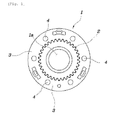
FIG. 1 is a diagram illustrating a gear plate 1 which is a component coupled with the seat cushion, in which a center of the gear plate is provided with acenter hole 1a and an external gear 2 is protrudedly formed around thecenter hole 1a. - Further, a
flange part 3 is formed around the external gear 2 and a plurality ofcoupling protrusions 4 are coupled with theflange part 3 by welding so that the gear plate 1 may be coupled with the seat cushion (not illustrated). In this case, the external gear 2 may be protrudedly formed on one surface of the gear plate 1 and thecoupling protrusion 4 may be protrudedly formed on the other surface of the gear plate 1. - Further, although not illustrated in the drawings, as a component coupled with the seat back, a mobile flange is provided. An inside of the mobile flange is provided with an internal gear and an operating unit for eccentrically rotating the mobile flange is provided between the gear plate and the mobile flange. That is, the mobile flange is rotated while the external gear on the gear plate being engaged with the internal gear, such that the seat back coupled with the mobile flange is rotated to adjust the angle of the seat back.
- However, in the case of the above-mentioned gear plate, since the coupling protrusion is positioned at an edge portion of the external gear, the flange part needs to be provided around the external gear to form the coupling protrusion. In this case, since the flange part is provided along the edge of the external gear, it is very difficult to reduce a weight of the gear plate due to the flange part.
- Further, since the coupling protrusion is coupled with the flange part by the welding, man hour may be increased and production and manufacturing costs of components may be increased.
- Further, since the operating unit provided between the gear plate and the mobile flange is configured to be exposed to the outside, components configuring the operating unit may be separated.
- The contents described as the related art have been provided only for assisting in the understanding for the background of the present invention and should not be considered as corresponding to the related art known to those skilled in the art.
- An object of the present invention is to provide a reclining apparatus for a vehicle seat capable of reducing a weight and cost of a gear plate by changing a formation position of a coupling protrusion and a method for forming a coupling protrusion.
- Another object of the present invention is to provide a reclining apparatus for a vehicle seat capable of preventing components from separating by covering an operating unit.
- In one general aspect, a reclining apparatus for a vehicle seat includes: a gear plate configured to be connected to a seat cushion, have an external gear formed on an outer circumference thereof, and have a coupling protrusion provided along a circumference thereof having a rotating radius smaller than that of the external gear; a mobile flange configured to be connected to the seat back, have an internal gear formed on an inner circumference thereof, and eccentrically engaged with the external gear; and an operating unit configured to be provided in an operation space between a center hole of the gear plate and a center hole of the mobile flange to make the mobile flange be relatively rotated to the gear plate while being eccentric to the gear plate.
- The coupling protrusion may be formed along a minimum rotating radius adjacent to the center hole of the gear plate.
- The other surface of the gear plate may be provided with a lightweight groove at a position corresponding to the coupling protrusion formed on one surface of the gear plate.
- The coupling protrusion may be integrally formed with the gear plate.
- One surface of the gear plate may be provided with a cap in a shape covering the operating unit to prevent the operating unit from separating.
- A locking jaw may be formed along an edge of the cap and the coupling protrusion may protrude toward an inside of the center hole of the gear plate to make the locking jaw be locked to a protruded portion of the coupling protrusion.
- As described above, according to the exemplary embodiments of the present invention, the coupling protrusion on the gear plate is provided along the inside circumference of the external gear, and as a result, the separate flange part for securing the formation position of the coupling protrusion is not required, thereby simplifying and minimizing the structure of the gear plate and implementing the miniaturization and weight reduction of the components.
- Further, the coupling protrusion is integrally formed with the gear plate to reduce the man hour required to form the coupling protrusion, thereby greatly saving the production and manufacturing cost of the gear plate and the cap is formed on the outside of the operating unit in a shape covering the operating unit, thereby effectively preventing the spring and the cams from separating to the outside.
-
-
FIG. 1 is a diagram illustrating a shape of a gear plate according to the related art. -
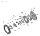
FIG. 2 is a diagram separately illustrating components configuring a reclining apparatus according to an exemplary embodiment of the present invention. -
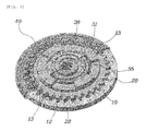
FIG. 3 is a perspective view illustrating a coupled configuration of the reclining apparatus according to the exemplary embodiment of the present invention. -
FIG. 4 is a cut-away perspective view of the reclining apparatus according to the exemplary embodiment of the present invention. -
FIG. 5 is a cut-away front view of the reclining apparatus according to the exemplary embodiment of the present invention. -
FIG. 6 is a cut-away perspective view of a gear plate according to an exemplary embodiment of the present invention. - Exemplary embodiments of the present invention will be described below in detail with reference to the accompanying drawings.
- Referring to
FIGS. 2 to 6 , a reclining apparatus for a vehicle seat according to an exemplary embodiment of the present invention may include agear plate 10 configured to be connected to a seat cushion (not illustrated), have anexternal gear 12 formed on an outer circumference thereof, and have acoupling protrusion 13 provided along a circumference thereof having a rotating radius smaller than that of theexternal gear 12, amobile flange 20 configured to be connected to the seat back (not illustrated), have aninternal gear 22 formed on an inner circumference thereof, and eccentrically engaged with theexternal gear 12, and anoperating unit 30 configured to be provided in an operation space between a center hole 11 of thegear plate 10 and acenter hole 21 of themobile flange 20 to make themobile flange 20 be relatively rotated to thegear plate 10 while being eccentric to thegear plate 10. - Referring in detail to
FIGS. 2 to 5 , thegear plate 10 is first coupled with the seat cushion through a bracket, and the like, a center thereof is provided with the center hole 11, an outer circumference thereof is provided with theexternal gear 12, and one surface thereof is provided with a plurality (four in the present invention) ofcoupling protrusions 13 so as to be coupled with the seat cushion. - In this case, the
external gear 12 may be provided along an outer circumference of an outermost portion of thegear plate 10 and thecoupling protrusion 13 may be provided along a circumferential direction of thegear plate 10 between theexternal gear 12 and the center hole 11. Further, an inner circumference of the center hole 11 of thegear plate 10 may be further provided with abush 15 and therefore a rotating operation of theoperating unit 30 may be more smoothly implemented. - The
mobile flange 20 is coupled with the seat back through the bracket, and the like and a center of themobile flange 20 is provided with thecenter hole 21 and themobile flange 20 has theinternal gear 22 provided along an inner circumference of one side thereof to make theexternal gear 12 on thegear plate 10 be engaged with theinternal gear 22. Further, the other side of themobile flange 20 may be provided with a plurality of protrusions along a circumferential direction to be coupled with the seat back. Further, themobile flange 20 may be coupled with aretainer 40 in a shape enclosing an outside of themobile flange 20. - Here, as illustrated in
FIG. 3 , the number of teeth of theexternal gear 12 of thegear plate 10 is one smaller than the number of teeth of theinternal gear 22 of themobile flange 20. Further, a diameter of theexternal gear 12 is formed to be smaller than that of theinternal gear 22 and thus themobile flange 20 is eccentrically engaged with thegear plate 10 to be eccentrically rotated. - As illustrated in
FIGS. 2 and4 , theoperating unit 30 is disposed in the operation space between thegear plate 10 and themobile flange 20 and is configured to largely include aninput shaft 31, afirst cam 32, asecond cam 33, athird cam 34, and aspring 35. - As described below, the
first cam 32 and thesecond cam 33 are formed in a ring shape so that one surface of thefirst cam 32 overlaps the other surface of thesecond cam 33 and an outer circumference of thefirst cam 32 is provided with a first locking part 32a and an outer circumference of thesecond cam 33 is provided with asecond locking part 33a to be rotatably inserted between the center hole 11 of thegear plate 10 and thecenter hole 21 of themobile flange 20. - That is, one end of the first locking part 32a faces one end of the
second locking part 33a and the other end of the first locking part 32a and the other end of thesecond locking part 33a overlap each other to face each other, such that thefirst cam 32 and thesecond cam 33 are applied with a relative rotating force to be rotated between the center hole 11 of thegear plate 10 and thecenter hole 21 of themobile flange 20. - Further, the
third cam 34 is formed to have approximately a semi-spherical shape and an inner circumference of thethird cam 34 is coupled with thefirst cam 32 and thesecond cam 33 while partially enclosing outer circumferences of thefirst cam 32 and thesecond cam 33. That is, one end of thethird cam 34 is coupled with an outer circumference of the first locking part 32a formed on thefirst cam 32 and the other end of thethird cam 34 is coupled with an outer circumference of thesecond locking part 33a formed on thesecond cam 33, such that thefirst cam 32 and thesecond cam 33 may be rotated together with thethird cam 34. - In this case, the operation space between the center hole 11 of the
gear plate 10 and thecenter hole 21 of themobile flange 20 is provided in an eccentric form and therefore the coupled form of thefirst cam 32, thesecond cam 33, and thethird cam 34 needs to be configured and assembled in an eccentric form which may be rotated while being inserted into the operation space of the eccentric form. - Further, the
center hole 21 of themobile flange 20 is rotatably inserted with theinput shaft 31 and one end of theinput shaft 31 is provided with anoperation piece 31a protruding to the cam side and theoperation piece 31a is configured to be locked between thesecond cam 33 and thethird cam 34, and thus thefirst cam 32, thesecond cam 33, and thethird cam 34 may be rotated by rotating theinput shaft 31. - Further, one surface of the
input shaft 31 is seated with aspring 35 having a torsion spring shape and both ends of thespring 35 are inserted into a space in which one end of thefirst cam 32 faces one end of thesecond cam 33 to provide an elastic force which simultaneously rotates thefirst cam 32 and thesecond cam 33. In this case, a center of theinput shaft 31 may be provided with a shaft hole having a spline shape so that an actuator may be coupled with a rotating shaft. - Meanwhile, according to the exemplary embodiment of the present invention, as illustrated in
FIGS. 2 and6 , thecoupling protrusion 13 may be formed along a minimum rotating radius adjacent to the center hole 11 of thegear plate 10. - That is, the
coupling protrusion 13 is formed along an edge between the center hole 11 of thegear plate 10 and theexternal gear 12 and is formed along the minimum rotating radius adjacent to the center hole 11 to minimize the diameter of thecoupling protrusion 13, such that the weight reduction of thegear plate 10 provided with thecoupling protrusion 13 is very effective. - According to the exemplary embodiment of the present invention, the other surface of the
gear plate 10 may be provided with alightweight groove 14 at a position corresponding to thecoupling protrusion 13 formed on one surface of thegear plate 10. - That is, one surface opposite to the
mobile flange 20 side is protrudedly provided with thecoupling protrusion 13 and the other surface toward themobile flange 20 side is provided with thelightweight groove 14 as much as the protrusion of thecoupling protrusion 13 to more reduce the weight of thegear plate 10. - According to the exemplary embodiment of the present invention, the
coupling protrusion 13 may be integrally formed with thegear plate 10, and therefore thecoupling protrusion 13 and thegear plate 10 are integrally processed during the manufacturing process of thegear plate 10 to reduce the man hour required to form thecoupling protrusion 13 and save the production and manufacturing costs of the components of thegear plate 10. Further, compared to thecoupling protrusion 4 fixed by the existing welding processing, the coupling force and durability of thecoupling protrusion 13 may be more increased. - Further, according to the exemplary embodiment of the present invention, as illustrated in
FIGS. 2 ,4, and 5 , one surface of thegear plate 10 is provided with acap 36 in a shape covering theoperating unit 30 to prevent theoperating unit 30 from separating. - To this end, a
locking jaw 36a is formed along an edge of thecap 36 and thecoupling protrusion 13 protrudes toward the inside of the center hole 11 of thegear plate 10 to make thelocking jaw 36a be locked to a protruded portion of thecoupling protrusion 13. - That is, the
coupling protrusion 13 protrudes toward the inside of the center hole 11 of thegear plate 10, and therefore the lockingjaw 36a formed at the edge of thecap 36 is coupled with thecoupling protrusion 13 in a form inserted into the protruded portion of thecoupling protrusion 13 to prevent thespring 35 and the cam from separating by thecap 36. - Here, when the
cap 36 is coupled with thecoupling protrusion 13, the lockingjaw 36a formed on thecap 36 is configured to be supported by thebush 15 and therefore the lockingjaw 36a may be stably inserted between thecoupling protrusion 13 and thebush 15. - The action and effect of the present invention will be described in detail with reference to
FIGS. 2 and4 . - When the actuator of the power reclining apparatus is driven by the switch manipulation, the
input shaft 31 starts to be rotated to provide an elastic force to thespring 35. - Next, when the
first cam 32 or thesecond cam 33 is rotated by the elastic force of thespring 35, thefirst cam 32 and thesecond cam 33 are coupled with thethird cam 34 and thus thethird cam 34 is rotated together with thefirst cam 32 and thesecond cam 33. In this case, thethird cam 34 is eccentrically formed and therefore is eccentrically rotated between the center hole 11 of thegear plate 10 and thecenter hole 21 of themobile flange 20. - Therefore, the
external gear 12 of thegear plate 10 is eccentrically engaged with theinternal gear 22 of themobile flange 20 and thus themobile flange 20 is eccentrically rotated to thegear plate 10, such that the seat back coupled with themobile flange 20 is rotated, thereby adjusting the angle of the seat back. - As such, according to the reclining apparatus for a vehicle seat according to the exemplary embodiment of the present invention, the
mobile flange 20 coupled with the seat back is rotatably engaged with thegear plate 10 to adjust the angle of the seat back depending on the rotating manipulation of themobile flange 20. - In particular, according to the exemplary embodiment of the present invention, the
coupling protrusion 13 on thegear plate 10 is formed along an inside circumference of theexternal gear 12 and thus the separate flange part need not be formed at the outside of theexternal gear 12 to form thecoupling protrusion 13, such that the structure of thegear plate 10 may be simplified and minimized, thereby reducing the weight of thegear plate 10 to realize the weight reduction of the components. - Further, according to the exemplary embodiment of the present invention, the
coupling protrusion 13 is integrally formed with thegear plate 10 to reduce the man hour required to form thecoupling protrusion 13, such that the production and manufacturing cost of thegear plate 10 may be greatly reduced. - In addition to this, according to the exemplary embodiment of the present invention, the outside of the operating
unit 30 is provided with thecap 36 in a shape covering the operatingunit 30 to effectively prevent thespring 35 and the cams from separating to the outside. - Meanwhile, although specific exemplary embodiments of the present invention have been described above in detail, it is obvious to those skilled in the art that various modifications and alterations may be made without departing from the spirit and scope of the present invention. In addition, it is obvious that these modifications and alterations are within the following claims.
-
- 10: GEAR PLATE 11: CENTER HOLE
- 12: EXTERNAL GEAR 13: COUPLING PROTRUSION
- 14: LIGHTWEIGHT GROOVE 15: BUSH
- 20: MOBILE FLANGE 21: CENTER HOLE
- 22: INTERNAL GEAR 30: OPERATING UNIT
- 31: INPUT SHAFT 32: FIRST CAM
- 33: SECOND CAM 34: THIRD CAM
- 35: SPRING 36: CAP
- 36a: LOCKING JAW 40: RETAINER
Claims (6)
- A reclining apparatus for a vehicle seat, comprising:a gear plate 10 configured to be connected to a seat cushion, have an external gear 12 formed on an outer circumference thereof, and have a coupling protrusion 13 provided along a circumference thereof having a rotating radius smaller than that of the external gear 12;a mobile flange 20 configured to be connected to a seat back, have an internal gear 22 formed on an inner circumference thereof, and eccentrically engaged with the external gear 12; andan operating unit 30 configured to be provided in an operation space between a center hole 11 of the gear plate 10 and a center hole 21 of the mobile flange 20 to make the mobile flange 20 be relatively rotated to the gear plate 10 while being eccentric to the gear plate 10.
- The reclining apparatus for a vehicle seat of claim 1, wherein the coupling protrusion 13 is formed along a minimum rotating radius adjacent to the center hole 11 of the gear plate 10.
- The reclining apparatus for a vehicle seat of claim 1, wherein the other surface of the gear plate 10 is provided with a lightweight groove 14 at a position corresponding to the coupling protrusion 13 formed on one surface of the gear plate 10.
- The reclining apparatus for a vehicle seat of claim 1, wherein the coupling protrusion 13 is integrally formed with the gear plate 10.
- The reclining apparatus for a vehicle seat of claim 1, wherein one surface of the gear plate 10 is provided with a cap 36 in a shape covering the operating unit 30 to prevent the operating unit 30 from separating.
- The reclining apparatus for a vehicle seat of claim 5, wherein a locking jaw 36a is formed along an edge of the cap 36 and the coupling protrusion 13 protrudes toward an inside of the center hole 11 of the gear plate 10 to make the locking jaw 36a be locked to a protruded portion of the coupling protrusion 13.
Applications Claiming Priority (2)
| Application Number | Priority Date | Filing Date | Title |
|---|---|---|---|
| KR1020120022766A KR101372952B1 (en) | 2012-03-06 | 2012-03-06 | Reclining Device for Vehicle Seat |
| PCT/KR2013/001784 WO2013133616A1 (en) | 2012-03-06 | 2013-03-06 | Reclining apparatus for vehicle seat |
Publications (3)
| Publication Number | Publication Date |
|---|---|
| EP2823992A1 true EP2823992A1 (en) | 2015-01-14 |
| EP2823992A4 EP2823992A4 (en) | 2015-12-02 |
| EP2823992B1 EP2823992B1 (en) | 2019-07-24 |
Family
ID=49117030
Family Applications (1)
| Application Number | Title | Priority Date | Filing Date |
|---|---|---|---|
| EP13758427.2A Active EP2823992B1 (en) | 2012-03-06 | 2013-03-06 | Reclining apparatus for vehicle seat |
Country Status (5)
| Country | Link |
|---|---|
| US (1) | US9381833B2 (en) |
| EP (1) | EP2823992B1 (en) |
| KR (1) | KR101372952B1 (en) |
| CN (1) | CN104302508A (en) |
| WO (1) | WO2013133616A1 (en) |
Families Citing this family (18)
| Publication number | Priority date | Publication date | Assignee | Title |
|---|---|---|---|---|
| KR101407256B1 (en) * | 2012-11-28 | 2014-06-13 | 현대다이모스(주) | Reclining apparatus for seat of vehicle |
| DE102012111941B4 (en) * | 2012-12-07 | 2022-03-03 | Keiper Seating Mechanisms Co., Ltd. | Seat fitting for a motor vehicle seat |
| KR101419700B1 (en) | 2014-05-20 | 2014-07-16 | 대원정밀공업(주) | Miniature round recliner |
| KR101565578B1 (en) | 2014-06-20 | 2015-11-04 | 현대다이모스(주) | Reclining device for vehicle seat |
| KR101705609B1 (en) * | 2015-07-16 | 2017-02-13 | 현대다이모스(주) | Apparatus for reclining seat |
| KR101659231B1 (en) * | 2015-07-16 | 2016-09-30 | 주식회사다스 | Recliner of vehicle seat |
| KR101793440B1 (en) | 2016-05-16 | 2017-11-06 | 주식회사 다스 | recliner of seat for car |
| JP6807708B2 (en) * | 2016-10-31 | 2021-01-06 | 株式会社Tf−Metal | Vehicle seat reclining device |
| CN108784082B (en) * | 2018-05-21 | 2021-08-20 | 延锋安道拓座椅有限公司 | An angle adjustable mechanism and a seat structure including the angle adjustable structure |
| KR102648188B1 (en) * | 2018-11-29 | 2024-03-14 | 현대자동차주식회사 | Seatback frame for vehicle |
| KR102684768B1 (en) * | 2019-05-24 | 2024-07-12 | 현대트랜시스 주식회사 | Seat recliner for vehicle |
| KR102360583B1 (en) * | 2020-03-31 | 2022-02-09 | 주식회사 다스 | Concentric type continuous recliner |
| CN114287762B (en) * | 2020-10-07 | 2024-01-30 | 大圆精密工业株式会社 | Electric reclining chair |
| KR102905589B1 (en) * | 2020-10-14 | 2025-12-30 | 현대트랜시스 주식회사 | Seat reclining device |
| KR102542569B1 (en) | 2021-08-10 | 2023-06-12 | 현대트랜시스 주식회사 | Seat recliner for vehicle seat |
| KR102542570B1 (en) | 2021-09-16 | 2023-06-12 | 현대트랜시스 주식회사 | Reclining apparatus for seat |
| KR102692991B1 (en) * | 2022-07-15 | 2024-08-06 | 현대트랜시스 주식회사 | Recliner for vehicle seat |
| KR20240020972A (en) * | 2022-08-09 | 2024-02-16 | 현대트랜시스 주식회사 | Recliner for vehicle seat |
Family Cites Families (17)
| Publication number | Priority date | Publication date | Assignee | Title |
|---|---|---|---|---|
| DE3129672C1 (en) * | 1981-07-28 | 1982-10-28 | Privates Institut für physikalisch technische Auftragsforschung GmbH, 6107 Reinheim | Locking and adjusting mechanism for vehicle seat - includes locking and adjusting drives with toothed arms and eccentric bushes |
| CA1283594C (en) * | 1987-09-01 | 1991-04-30 | Peter Kershaw | Double stage taumel gear reduction unit |
| JP4608751B2 (en) | 2000-08-30 | 2011-01-12 | アイシン精機株式会社 | Vehicle seat reclining device |
| JP4989869B2 (en) | 2004-12-28 | 2012-08-01 | デルタ工業株式会社 | Bracket angle adjustment device |
| JP4676756B2 (en) * | 2004-12-28 | 2011-04-27 | デルタ工業株式会社 | Bracket angle adjustment device |
| JP4935423B2 (en) | 2007-02-28 | 2012-05-23 | トヨタ紡織株式会社 | Connecting device |
| JP5177134B2 (en) * | 2007-05-08 | 2013-04-03 | トヨタ紡織株式会社 | Connecting device |
| WO2009019908A1 (en) | 2007-08-08 | 2009-02-12 | Toyota Boshoku Kabushiki Kaisha | Rotation stopper for vehicle seat |
| KR20090017775A (en) * | 2007-08-16 | 2009-02-19 | 주식회사다스 | Seat back reclining device |
| US8746796B2 (en) | 2009-03-12 | 2014-06-10 | Magna Seating Inc. | Anti-backdrive for continuous disc recliner |
| DE102009038562B3 (en) * | 2009-08-19 | 2011-02-24 | Keiper Gmbh & Co. Kg | Fitting for a vehicle seat and vehicle seat |
| DE102009052512A1 (en) * | 2009-11-11 | 2011-05-12 | Johnson Controls Gmbh | Tilt adjuster for vehicles |
| KR101072789B1 (en) | 2010-03-11 | 2011-10-14 | 주식회사 오스템 | dial recliner |
| DE102010018952B4 (en) * | 2010-04-28 | 2013-03-14 | Keiper Gmbh & Co. Kg | Fitting for a vehicle seat, vehicle seat and method for assembling a fitting |
| WO2012001769A1 (en) | 2010-06-29 | 2012-01-05 | 株式会社今仙電機製作所 | Seat reclining device for tiltably holding seat back |
| FR2963288B1 (en) * | 2010-07-29 | 2014-04-25 | Faurecia Sieges Automobile | JOINT MECHANISM AND VEHICLE SEAT COMPRISING SUCH A MECHANISM. |
| KR101003718B1 (en) * | 2010-08-03 | 2010-12-24 | 대원정밀공업(주) | Stepless adjustable recliner for car seats |
-
2012
- 2012-03-06 KR KR1020120022766A patent/KR101372952B1/en active Active
-
2013
- 2013-03-06 CN CN201380023260.4A patent/CN104302508A/en active Pending
- 2013-03-06 WO PCT/KR2013/001784 patent/WO2013133616A1/en not_active Ceased
- 2013-03-06 EP EP13758427.2A patent/EP2823992B1/en active Active
- 2013-03-06 US US14/383,855 patent/US9381833B2/en active Active
Also Published As
| Publication number | Publication date |
|---|---|
| WO2013133616A1 (en) | 2013-09-12 |
| KR101372952B1 (en) | 2014-03-10 |
| EP2823992B1 (en) | 2019-07-24 |
| EP2823992A4 (en) | 2015-12-02 |
| US9381833B2 (en) | 2016-07-05 |
| CN104302508A (en) | 2015-01-21 |
| KR20130101765A (en) | 2013-09-16 |
| US20150054324A1 (en) | 2015-02-26 |
Similar Documents
| Publication | Publication Date | Title |
|---|---|---|
| EP2823992A1 (en) | Reclining apparatus for vehicle seat | |
| JP5006087B2 (en) | Vehicle seat reclining device | |
| US10065538B2 (en) | Articulation mechanism and vehicle seat having such a mechanism | |
| EP3208140B1 (en) | Torque transfer control mechanism and seat structure | |
| CN107380019B (en) | Vehicle seat used angle demodulator | |
| EP2823993B1 (en) | Reclining apparatus for vehicle seat | |
| KR101427567B1 (en) | Recliner for Motor Vehicle having Wedge | |
| KR101591696B1 (en) | Seat fitting for a motor vehicle seat | |
| KR101959006B1 (en) | Recliner for vehicle seat | |
| JP4831308B2 (en) | Vehicle seat reclining device | |
| CN113103933B (en) | Stable folder | |
| KR20150063696A (en) | Recliner of vehicle seet | |
| CN110497825B (en) | Concentric drive recliner and car seat | |
| KR101034308B1 (en) | Oldham Coupling Type Reclining Device for Vehicle Seat | |
| KR101260890B1 (en) | Recliner device for car seat | |
| KR101034309B1 (en) | Oldham Coupling Type Reclining Device for Vehicle Seat | |
| KR101072789B1 (en) | dial recliner | |
| KR101073457B1 (en) | A reclinning devece for seats for vehicles | |
| KR101251797B1 (en) | Recliner device of vehicle seat | |
| KR101251838B1 (en) | Recliner device of vehicle seat | |
| KR20210026362A (en) | Seat Recling Device for Automobile | |
| KR101662552B1 (en) | Assembly structure of seat-back | |
| CN221340313U (en) | Recliner, seat and vehicle having the same | |
| KR101107987B1 (en) | Car seat reclining device | |
| KR20120036609A (en) | Mounting method of reclining device |
Legal Events
| Date | Code | Title | Description |
|---|---|---|---|
| PUAI | Public reference made under article 153(3) epc to a published international application that has entered the european phase |
Free format text: ORIGINAL CODE: 0009012 |
|
| 17P | Request for examination filed |
Effective date: 20141006 |
|
| AK | Designated contracting states |
Kind code of ref document: A1 Designated state(s): AL AT BE BG CH CY CZ DE DK EE ES FI FR GB GR HR HU IE IS IT LI LT LU LV MC MK MT NL NO PL PT RO RS SE SI SK SM TR |
|
| AX | Request for extension of the european patent |
Extension state: BA ME |
|
| DAX | Request for extension of the european patent (deleted) | ||
| RA4 | Supplementary search report drawn up and despatched (corrected) |
Effective date: 20151102 |
|
| RIC1 | Information provided on ipc code assigned before grant |
Ipc: B60N 2/20 20060101ALI20151027BHEP Ipc: B60N 2/225 20060101ALI20151027BHEP Ipc: B60N 2/22 20060101AFI20151027BHEP |
|
| STAA | Information on the status of an ep patent application or granted ep patent |
Free format text: STATUS: EXAMINATION IS IN PROGRESS |
|
| 17Q | First examination report despatched |
Effective date: 20170202 |
|
| GRAP | Despatch of communication of intention to grant a patent |
Free format text: ORIGINAL CODE: EPIDOSNIGR1 |
|
| STAA | Information on the status of an ep patent application or granted ep patent |
Free format text: STATUS: GRANT OF PATENT IS INTENDED |
|
| INTG | Intention to grant announced |
Effective date: 20190212 |
|
| GRAS | Grant fee paid |
Free format text: ORIGINAL CODE: EPIDOSNIGR3 |
|
| GRAA | (expected) grant |
Free format text: ORIGINAL CODE: 0009210 |
|
| STAA | Information on the status of an ep patent application or granted ep patent |
Free format text: STATUS: THE PATENT HAS BEEN GRANTED |
|
| AK | Designated contracting states |
Kind code of ref document: B1 Designated state(s): AL AT BE BG CH CY CZ DE DK EE ES FI FR GB GR HR HU IE IS IT LI LT LU LV MC MK MT NL NO PL PT RO RS SE SI SK SM TR |
|
| REG | Reference to a national code |
Ref country code: GB Ref legal event code: FG4D |
|
| REG | Reference to a national code |
Ref country code: CH Ref legal event code: EP |
|
| REG | Reference to a national code |
Ref country code: DE Ref legal event code: R096 Ref document number: 602013058194 Country of ref document: DE |
|
| REG | Reference to a national code |
Ref country code: AT Ref legal event code: REF Ref document number: 1157771 Country of ref document: AT Kind code of ref document: T Effective date: 20190815 |
|
| REG | Reference to a national code |
Ref country code: IE Ref legal event code: FG4D |
|
| REG | Reference to a national code |
Ref country code: NL Ref legal event code: MP Effective date: 20190724 |
|
| REG | Reference to a national code |
Ref country code: LT Ref legal event code: MG4D |
|
| REG | Reference to a national code |
Ref country code: AT Ref legal event code: MK05 Ref document number: 1157771 Country of ref document: AT Kind code of ref document: T Effective date: 20190724 |
|
| PG25 | Lapsed in a contracting state [announced via postgrant information from national office to epo] |
Ref country code: FI Free format text: LAPSE BECAUSE OF FAILURE TO SUBMIT A TRANSLATION OF THE DESCRIPTION OR TO PAY THE FEE WITHIN THE PRESCRIBED TIME-LIMIT Effective date: 20190724 Ref country code: AT Free format text: LAPSE BECAUSE OF FAILURE TO SUBMIT A TRANSLATION OF THE DESCRIPTION OR TO PAY THE FEE WITHIN THE PRESCRIBED TIME-LIMIT Effective date: 20190724 Ref country code: NO Free format text: LAPSE BECAUSE OF FAILURE TO SUBMIT A TRANSLATION OF THE DESCRIPTION OR TO PAY THE FEE WITHIN THE PRESCRIBED TIME-LIMIT Effective date: 20191024 Ref country code: SE Free format text: LAPSE BECAUSE OF FAILURE TO SUBMIT A TRANSLATION OF THE DESCRIPTION OR TO PAY THE FEE WITHIN THE PRESCRIBED TIME-LIMIT Effective date: 20190724 Ref country code: BG Free format text: LAPSE BECAUSE OF FAILURE TO SUBMIT A TRANSLATION OF THE DESCRIPTION OR TO PAY THE FEE WITHIN THE PRESCRIBED TIME-LIMIT Effective date: 20191024 Ref country code: PT Free format text: LAPSE BECAUSE OF FAILURE TO SUBMIT A TRANSLATION OF THE DESCRIPTION OR TO PAY THE FEE WITHIN THE PRESCRIBED TIME-LIMIT Effective date: 20191125 Ref country code: HR Free format text: LAPSE BECAUSE OF FAILURE TO SUBMIT A TRANSLATION OF THE DESCRIPTION OR TO PAY THE FEE WITHIN THE PRESCRIBED TIME-LIMIT Effective date: 20190724 Ref country code: NL Free format text: LAPSE BECAUSE OF FAILURE TO SUBMIT A TRANSLATION OF THE DESCRIPTION OR TO PAY THE FEE WITHIN THE PRESCRIBED TIME-LIMIT Effective date: 20190724 Ref country code: LT Free format text: LAPSE BECAUSE OF FAILURE TO SUBMIT A TRANSLATION OF THE DESCRIPTION OR TO PAY THE FEE WITHIN THE PRESCRIBED TIME-LIMIT Effective date: 20190724 |
|
| PG25 | Lapsed in a contracting state [announced via postgrant information from national office to epo] |
Ref country code: IS Free format text: LAPSE BECAUSE OF FAILURE TO SUBMIT A TRANSLATION OF THE DESCRIPTION OR TO PAY THE FEE WITHIN THE PRESCRIBED TIME-LIMIT Effective date: 20191124 Ref country code: RS Free format text: LAPSE BECAUSE OF FAILURE TO SUBMIT A TRANSLATION OF THE DESCRIPTION OR TO PAY THE FEE WITHIN THE PRESCRIBED TIME-LIMIT Effective date: 20190724 Ref country code: LV Free format text: LAPSE BECAUSE OF FAILURE TO SUBMIT A TRANSLATION OF THE DESCRIPTION OR TO PAY THE FEE WITHIN THE PRESCRIBED TIME-LIMIT Effective date: 20190724 Ref country code: AL Free format text: LAPSE BECAUSE OF FAILURE TO SUBMIT A TRANSLATION OF THE DESCRIPTION OR TO PAY THE FEE WITHIN THE PRESCRIBED TIME-LIMIT Effective date: 20190724 Ref country code: ES Free format text: LAPSE BECAUSE OF FAILURE TO SUBMIT A TRANSLATION OF THE DESCRIPTION OR TO PAY THE FEE WITHIN THE PRESCRIBED TIME-LIMIT Effective date: 20190724 Ref country code: GR Free format text: LAPSE BECAUSE OF FAILURE TO SUBMIT A TRANSLATION OF THE DESCRIPTION OR TO PAY THE FEE WITHIN THE PRESCRIBED TIME-LIMIT Effective date: 20191025 |
|
| PG25 | Lapsed in a contracting state [announced via postgrant information from national office to epo] |
Ref country code: TR Free format text: LAPSE BECAUSE OF FAILURE TO SUBMIT A TRANSLATION OF THE DESCRIPTION OR TO PAY THE FEE WITHIN THE PRESCRIBED TIME-LIMIT Effective date: 20190724 |
|
| PG25 | Lapsed in a contracting state [announced via postgrant information from national office to epo] |
Ref country code: EE Free format text: LAPSE BECAUSE OF FAILURE TO SUBMIT A TRANSLATION OF THE DESCRIPTION OR TO PAY THE FEE WITHIN THE PRESCRIBED TIME-LIMIT Effective date: 20190724 Ref country code: PL Free format text: LAPSE BECAUSE OF FAILURE TO SUBMIT A TRANSLATION OF THE DESCRIPTION OR TO PAY THE FEE WITHIN THE PRESCRIBED TIME-LIMIT Effective date: 20190724 Ref country code: DK Free format text: LAPSE BECAUSE OF FAILURE TO SUBMIT A TRANSLATION OF THE DESCRIPTION OR TO PAY THE FEE WITHIN THE PRESCRIBED TIME-LIMIT Effective date: 20190724 Ref country code: RO Free format text: LAPSE BECAUSE OF FAILURE TO SUBMIT A TRANSLATION OF THE DESCRIPTION OR TO PAY THE FEE WITHIN THE PRESCRIBED TIME-LIMIT Effective date: 20190724 Ref country code: IT Free format text: LAPSE BECAUSE OF FAILURE TO SUBMIT A TRANSLATION OF THE DESCRIPTION OR TO PAY THE FEE WITHIN THE PRESCRIBED TIME-LIMIT Effective date: 20190724 |
|
| PG25 | Lapsed in a contracting state [announced via postgrant information from national office to epo] |
Ref country code: SK Free format text: LAPSE BECAUSE OF FAILURE TO SUBMIT A TRANSLATION OF THE DESCRIPTION OR TO PAY THE FEE WITHIN THE PRESCRIBED TIME-LIMIT Effective date: 20190724 Ref country code: SM Free format text: LAPSE BECAUSE OF FAILURE TO SUBMIT A TRANSLATION OF THE DESCRIPTION OR TO PAY THE FEE WITHIN THE PRESCRIBED TIME-LIMIT Effective date: 20190724 Ref country code: CZ Free format text: LAPSE BECAUSE OF FAILURE TO SUBMIT A TRANSLATION OF THE DESCRIPTION OR TO PAY THE FEE WITHIN THE PRESCRIBED TIME-LIMIT Effective date: 20190724 Ref country code: IS Free format text: LAPSE BECAUSE OF FAILURE TO SUBMIT A TRANSLATION OF THE DESCRIPTION OR TO PAY THE FEE WITHIN THE PRESCRIBED TIME-LIMIT Effective date: 20200224 |
|
| REG | Reference to a national code |
Ref country code: DE Ref legal event code: R097 Ref document number: 602013058194 Country of ref document: DE |
|
| PLBE | No opposition filed within time limit |
Free format text: ORIGINAL CODE: 0009261 |
|
| STAA | Information on the status of an ep patent application or granted ep patent |
Free format text: STATUS: NO OPPOSITION FILED WITHIN TIME LIMIT |
|
| PG2D | Information on lapse in contracting state deleted |
Ref country code: IS |
|
| 26N | No opposition filed |
Effective date: 20200603 |
|
| PG25 | Lapsed in a contracting state [announced via postgrant information from national office to epo] |
Ref country code: SI Free format text: LAPSE BECAUSE OF FAILURE TO SUBMIT A TRANSLATION OF THE DESCRIPTION OR TO PAY THE FEE WITHIN THE PRESCRIBED TIME-LIMIT Effective date: 20190724 |
|
| PG25 | Lapsed in a contracting state [announced via postgrant information from national office to epo] |
Ref country code: MC Free format text: LAPSE BECAUSE OF FAILURE TO SUBMIT A TRANSLATION OF THE DESCRIPTION OR TO PAY THE FEE WITHIN THE PRESCRIBED TIME-LIMIT Effective date: 20190724 |
|
| REG | Reference to a national code |
Ref country code: CH Ref legal event code: PL |
|
| REG | Reference to a national code |
Ref country code: BE Ref legal event code: MM Effective date: 20200331 |
|
| PG25 | Lapsed in a contracting state [announced via postgrant information from national office to epo] |
Ref country code: LU Free format text: LAPSE BECAUSE OF NON-PAYMENT OF DUE FEES Effective date: 20200306 |
|
| PG25 | Lapsed in a contracting state [announced via postgrant information from national office to epo] |
Ref country code: LI Free format text: LAPSE BECAUSE OF NON-PAYMENT OF DUE FEES Effective date: 20200331 Ref country code: IE Free format text: LAPSE BECAUSE OF NON-PAYMENT OF DUE FEES Effective date: 20200306 Ref country code: CH Free format text: LAPSE BECAUSE OF NON-PAYMENT OF DUE FEES Effective date: 20200331 Ref country code: FR Free format text: LAPSE BECAUSE OF NON-PAYMENT OF DUE FEES Effective date: 20200331 |
|
| PG25 | Lapsed in a contracting state [announced via postgrant information from national office to epo] |
Ref country code: BE Free format text: LAPSE BECAUSE OF NON-PAYMENT OF DUE FEES Effective date: 20200331 |
|
| GBPC | Gb: european patent ceased through non-payment of renewal fee |
Effective date: 20200306 |
|
| PG25 | Lapsed in a contracting state [announced via postgrant information from national office to epo] |
Ref country code: GB Free format text: LAPSE BECAUSE OF NON-PAYMENT OF DUE FEES Effective date: 20200306 |
|
| PG25 | Lapsed in a contracting state [announced via postgrant information from national office to epo] |
Ref country code: MT Free format text: LAPSE BECAUSE OF FAILURE TO SUBMIT A TRANSLATION OF THE DESCRIPTION OR TO PAY THE FEE WITHIN THE PRESCRIBED TIME-LIMIT Effective date: 20190724 Ref country code: CY Free format text: LAPSE BECAUSE OF FAILURE TO SUBMIT A TRANSLATION OF THE DESCRIPTION OR TO PAY THE FEE WITHIN THE PRESCRIBED TIME-LIMIT Effective date: 20190724 |
|
| PG25 | Lapsed in a contracting state [announced via postgrant information from national office to epo] |
Ref country code: MK Free format text: LAPSE BECAUSE OF FAILURE TO SUBMIT A TRANSLATION OF THE DESCRIPTION OR TO PAY THE FEE WITHIN THE PRESCRIBED TIME-LIMIT Effective date: 20190724 |
|
| PGFP | Annual fee paid to national office [announced via postgrant information from national office to epo] |
Ref country code: DE Payment date: 20260220 Year of fee payment: 14 |