EP2823963A1 - Liquid ejection device - Google Patents
Liquid ejection device Download PDFInfo
- Publication number
- EP2823963A1 EP2823963A1 EP13757373.9A EP13757373A EP2823963A1 EP 2823963 A1 EP2823963 A1 EP 2823963A1 EP 13757373 A EP13757373 A EP 13757373A EP 2823963 A1 EP2823963 A1 EP 2823963A1
- Authority
- EP
- European Patent Office
- Prior art keywords
- liquid
- liquid ejecting
- ejecting apparatus
- ink
- carriage
- Prior art date
- Legal status (The legal status is an assumption and is not a legal conclusion. Google has not performed a legal analysis and makes no representation as to the accuracy of the status listed.)
- Ceased
Links
- 239000007788 liquid Substances 0.000 title claims abstract description 163
- 238000007639 printing Methods 0.000 description 12
- 238000012986 modification Methods 0.000 description 9
- 230000004048 modification Effects 0.000 description 9
- 230000001105 regulatory effect Effects 0.000 description 5
- 239000003086 colorant Substances 0.000 description 4
- 238000000034 method Methods 0.000 description 4
- 238000000926 separation method Methods 0.000 description 3
- 239000002184 metal Substances 0.000 description 2
- 238000012545 processing Methods 0.000 description 2
- 229920005989 resin Polymers 0.000 description 2
- 239000011347 resin Substances 0.000 description 2
- 239000000853 adhesive Substances 0.000 description 1
- 230000001070 adhesive effect Effects 0.000 description 1
- 239000002390 adhesive tape Substances 0.000 description 1
- 238000005452 bending Methods 0.000 description 1
- 230000000295 complement effect Effects 0.000 description 1
- 238000012937 correction Methods 0.000 description 1
- 230000007547 defect Effects 0.000 description 1
- 238000013461 design Methods 0.000 description 1
- 238000007599 discharging Methods 0.000 description 1
- 230000000694 effects Effects 0.000 description 1
- 238000005516 engineering process Methods 0.000 description 1
- 239000011521 glass Substances 0.000 description 1
- 239000000463 material Substances 0.000 description 1
- 229910044991 metal oxide Inorganic materials 0.000 description 1
- 150000004706 metal oxides Chemical class 0.000 description 1
- 239000002245 particle Substances 0.000 description 1
- 239000004065 semiconductor Substances 0.000 description 1
- 238000011144 upstream manufacturing Methods 0.000 description 1
Images





Classifications
-
- B—PERFORMING OPERATIONS; TRANSPORTING
- B41—PRINTING; LINING MACHINES; TYPEWRITERS; STAMPS
- B41J—TYPEWRITERS; SELECTIVE PRINTING MECHANISMS, i.e. MECHANISMS PRINTING OTHERWISE THAN FROM A FORME; CORRECTION OF TYPOGRAPHICAL ERRORS
- B41J25/00—Actions or mechanisms not otherwise provided for
- B41J25/001—Mechanisms for bodily moving print heads or carriages parallel to the paper surface
-
- B—PERFORMING OPERATIONS; TRANSPORTING
- B41—PRINTING; LINING MACHINES; TYPEWRITERS; STAMPS
- B41J—TYPEWRITERS; SELECTIVE PRINTING MECHANISMS, i.e. MECHANISMS PRINTING OTHERWISE THAN FROM A FORME; CORRECTION OF TYPOGRAPHICAL ERRORS
- B41J2/00—Typewriters or selective printing mechanisms characterised by the printing or marking process for which they are designed
- B41J2/005—Typewriters or selective printing mechanisms characterised by the printing or marking process for which they are designed characterised by bringing liquid or particles selectively into contact with a printing material
- B41J2/01—Ink jet
- B41J2/17—Ink jet characterised by ink handling
- B41J2/175—Ink supply systems ; Circuit parts therefor
-
- B—PERFORMING OPERATIONS; TRANSPORTING
- B41—PRINTING; LINING MACHINES; TYPEWRITERS; STAMPS
- B41J—TYPEWRITERS; SELECTIVE PRINTING MECHANISMS, i.e. MECHANISMS PRINTING OTHERWISE THAN FROM A FORME; CORRECTION OF TYPOGRAPHICAL ERRORS
- B41J2/00—Typewriters or selective printing mechanisms characterised by the printing or marking process for which they are designed
- B41J2/005—Typewriters or selective printing mechanisms characterised by the printing or marking process for which they are designed characterised by bringing liquid or particles selectively into contact with a printing material
- B41J2/01—Ink jet
-
- B—PERFORMING OPERATIONS; TRANSPORTING
- B41—PRINTING; LINING MACHINES; TYPEWRITERS; STAMPS
- B41J—TYPEWRITERS; SELECTIVE PRINTING MECHANISMS, i.e. MECHANISMS PRINTING OTHERWISE THAN FROM A FORME; CORRECTION OF TYPOGRAPHICAL ERRORS
- B41J2/00—Typewriters or selective printing mechanisms characterised by the printing or marking process for which they are designed
- B41J2/005—Typewriters or selective printing mechanisms characterised by the printing or marking process for which they are designed characterised by bringing liquid or particles selectively into contact with a printing material
- B41J2/01—Ink jet
- B41J2/17—Ink jet characterised by ink handling
- B41J2/175—Ink supply systems ; Circuit parts therefor
- B41J2/17503—Ink cartridges
- B41J2/17506—Refilling of the cartridge
- B41J2/17509—Whilst mounted in the printer
-
- B—PERFORMING OPERATIONS; TRANSPORTING
- B41—PRINTING; LINING MACHINES; TYPEWRITERS; STAMPS
- B41J—TYPEWRITERS; SELECTIVE PRINTING MECHANISMS, i.e. MECHANISMS PRINTING OTHERWISE THAN FROM A FORME; CORRECTION OF TYPOGRAPHICAL ERRORS
- B41J29/00—Details of, or accessories for, typewriters or selective printing mechanisms not otherwise provided for
- B41J29/02—Framework
-
- B—PERFORMING OPERATIONS; TRANSPORTING
- B41—PRINTING; LINING MACHINES; TYPEWRITERS; STAMPS
- B41J—TYPEWRITERS; SELECTIVE PRINTING MECHANISMS, i.e. MECHANISMS PRINTING OTHERWISE THAN FROM A FORME; CORRECTION OF TYPOGRAPHICAL ERRORS
- B41J29/00—Details of, or accessories for, typewriters or selective printing mechanisms not otherwise provided for
- B41J29/12—Guards, shields or dust excluders
- B41J29/13—Cases or covers
Definitions
- the present invention relates to a liquid ejecting apparatus which ejects a liquid onto a recording medium from a liquid ejecting head mounted on a carriage.
- An ink jet printer has been widely known as a liquid ejecting apparatus which ejects a liquid onto a recording medium from a liquid ejecting head.
- the inkjet printer includes a carriage and a recording head mounted on the carriage.
- the ink jet printer performs printing on a recording sheet by ejecting an ink (liquid) from a nozzle formed on the recording head while moving the carriage to perform scanning with respect to the recording sheet (recording medium).
- the ink jet printer includes one in which an ink cartridge supplying the ink to the recording head is mounted on the carriage (on-carriage type).
- the ink cartridge is detachably attached to the carriage.
- a large size ink tank is arranged laterally outside of an ink jet printer main body for all available colors.
- a tube is laid across a carriage from a side portion of the ink jet printer main body.
- the invention when additionally arranging the ink tank for the ink jet printer main body, aims to optimize a tube arrangement route arranged between the ink tank and the carriage as a first object, and when a large size ink tank is prepared for black color only, further aims to optimize the tube arrangement route for the user who rarely performs the color printing as a second object.
- a liquid ejecting apparatus includes a liquid ejecting apparatus main body ejecting a liquid onto a recording medium from a liquid ejecting head mounted on a carriage; and a liquid supply tube that introduces the liquid supplied from a liquid containing body which contains the liquid to the liquid ejecting head, having a transformable moving unit which is transformed following the movement of the liquid ejecting head, in which an inner space is provided which is formed from a discharge port including a region where the recording medium is discharged, and the liquid containing body is arranged in the inner space.
- the discharge port is configured to have a sheet discharge region and a space other than the sheet discharge region.
- the liquid containing body is arranged in a region overlapped with a transport route of the recording medium.
- the liquid ejecting apparatus further includes a tube fixing member laid along a scanning direction of the liquid ejecting head, in which a portion of the liquid supply tube is fixed to the tube fixing member, and the liquid supply tube is laid across the tube fixing member and the carriage.
- the tube fixing member is a member with a flat plate shape.
- the liquid ejecting apparatus further includes an ink mounting table having a flat plate section arranged above the transport route of the recording medium, in which the liquid containing body is placed on the flat plate section.
- the ink mounting table has leg portions supporting the flat plate section at both end sides in the scanning direction of the carriage, and the ink mounting table is arranged across the sheet discharge region from the region other than the sheet discharge region.
- the inner space is exposed from an upper surface opening of an apparatus housing which covers the liquid ejecting apparatus main body, at both end sides in the scanning direction of the carriage, the ink mounting table has a suspending section that suspends the flat plate section from the upper surface opening to the inner space, and the ink mounting table is arranged by suspending the sheet discharge region from the region other than the sheet discharge region.
- a plurality of the liquid containing bodies is provided, and a plurality of the liquid containing bodies is arranged along the scanning direction of the carriage.
- a plurality of the liquid containing bodies is provided, and a plurality of the liquid containing bodies is arranged along the transport direction.
- a plurality of the liquid containing bodies is provided, and a plurality of the liquid containing bodies is arranged along a vertical direction.
- a plurality of the liquid containing bodies is provided, a portion of a plurality of the liquid containing bodies is arranged in the inner space, and remaining portion of the liquid containing bodies is arranged outside the liquid ejecting apparatus main body.
- the liquid ejecting apparatus further includes an operation unit having a tilting mechanism on a front surface at the discharge port side of the liquid ejecting apparatus main body, in which the operation unit is fixed in a tilted state.
- the liquid ejecting apparatus further includes an operation unit on a front surface at the discharge port side of the liquid ejecting apparatus main body, in which the operation unit is provided with a cover body arranged above the liquid ejecting apparatus main body.
- An image reader reading out an image of the recording medium is arranged to be closely mountable above the liquid ejecting apparatus main body, and the inner space is formed on a region overlapped with the image reader.
- a liquid ejecting apparatus includes a carriage reciprocating, being provided with a liquid ejecting head ejecting a liquid onto a recording medium; a liquid ejecting apparatus main body containing the carriage; and a liquid containing body containing the liquid supplied to the liquid ejecting head, communicating with the liquid ejecting head via a liquid tube, in which the carriage includes an adapter to which an opposite side of the liquid tube to the liquid containing body is connected and which communicates with the liquid ejecting head, and a liquid container storing the liquid to be supplied to the liquid ejecting head.
- the liquid containing body is mounted on the inner space inside the liquid ejecting apparatus main body.
- the liquid containing body is mounted on the outside of the liquid ejecting apparatus main body.
- a multi-function printer 1 according to a first embodiment of the invention will be described.
- a transport direction (sub-scanning) of a recording sheet P represents an X direction
- a scanning direction (horizontal direction) of a carriage 81 represents a Y direction
- a vertical direction represents a Z direction.
- a downstream side (+ X direction) in the transport direction of the recording sheet P (recording medium) is referred to as forward and an upstream side (- X direction) is referred to as rearward.
- the + Y direction is referred to as a left side and the - Y direction is referred to as a right side.
- the + Z direction is referred to as upward and the -Z direction is referred to as downward.
- Fig. 1 is a perspective appearance view illustrating the multi-function printer 1 according to the first embodiment of the invention.
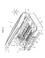
- Fig. 2 is a perspective view illustrating the multi-function printer when a scanner unit 3 is in an open state.
- the multi-function printer (liquid ejecting apparatus) 1 integrally includes a printer unit 2 which is an apparatus main body, and a scanner unit 3 which is an upper unit arranged above the printer unit 2.
- the multi-function printer 1 includes an ink container (liquid containing body) 110 inside (front inside space S) the printer unit 2.
- the scanner unit 3 is pivotally supported by the printer unit 2 through an opening/closing unit 4 at a rear end portion, and covers an upper section of the printer unit 2 to be capable of opening/closing.
- the scanner unit 3 closes the upper surface opening 10.
- the scanner unit 3 includes an upper frame 11 made of resins, an image reader (not illustrated) contained in the upper frame 11 and an upper cover 13 pivotally supported by an upper portion of the upper frame 11.
- Configuring members of the scanner unit 3 side of the opening/closing unit 4 are disposed at a rear end portion of the upper frame 11.
- the upper frame 11 includes a box type lower case 16 containing the image reader (not illustrated), and an upper case 17 covering a top side of the lower case 16.
- a manuscript mounting plate made of glass is widely arranged on the upper case 17 (not illustrated).
- a reading medium whose reading surface faces downward is mounted on the manuscript mounting plate.
- the image reader (not illustrated) contained in the lower case 16 includes a line sensor type sensor unit (not illustrated).
- the sensor unit has an image sensor (sensor portion) which is a Charge Coupled Device (CCD) type line sensor extending in the X direction, and reciprocates in the Y direction. This enables the image of the reading medium (manuscript) to be read on the manuscript mounting plate.
- CCD Charge Coupled Device
- CMOS Complementary Metal Oxide Semiconductor
- the printer unit (liquid ejecting apparatus main body) 2 includes a transport unit 61 transporting a sheet of the recording sheet P along a transport route R, a printing unit 62 arranged above the transport route R, performing a printing process on the recording sheet P by way of an ink jet method, a panel type operation unit 63 arranged on a front surface, an apparatus frame 64 on which the transport unit 61, the printing unit 62 and the operation unit 63 are mounted, and an apparatus housing 65 covering these.
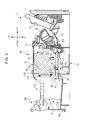
- Fig. 3 is a cross-sectional view in a side view, illustrating an internal structure of the printer unit 2 and an arrangement route for a tube 120.
- the printing unit 62 includes a guide frame 71 made of sheet metal, supporting the apparatus frame 64 and fully extending to a width in the Y direction, a carriage unit 72 supported by the guide frame 71 to freely reciprocate, and a carriage moving mechanism 73 (refer to Fig. 2 ) allowing the carriage unit 72 to reciprocate along the guide frame 71.
- the carriage unit 72 includes a box shaped carriage 81 supported by the guide frame 71 to freely reciprocate through an engagement slider portion 81a, an ink jet head 83 integrally incorporated on a lower surface of the carriage 81, and four ink cartridges (ink cartridge 85 with one ink cartridge adapter 84 and three liquid containers) contained in the carriage 81 to be attachable and detachable.
- the ink jet head (liquid ejecting head) 83 has four nozzle rows (not illustrated) ejecting four colors of ink drops.
- Four cartridges (ink cartridge adapter 84 and ink cartridge 85) storing the four colors of ink are mounted on the carriage 81.
- Four cartridges (ink cartridge adapter 84 and ink cartridge 85) are directly connected to an upper surface side of the ink jet head 83.
- the ink cartridge adapter 84 is supplied with a black ink from an ink container 110 (to be described later).
- Three ink cartridges 85 store cyan, magenta and yellow ink.
- the transport unit 61 includes a movable type sheet tray 91 setting the recording sheet in a right alignment manner, a separation roller 92 which sends separated recording sheets P one by one by separating the recording sheets P from the sheet tray 91, a feed roller 93 located downstream from the separation roller 92 and sending the recording sheet P to the printing unit 62 along the transport route R, a medium regulating member 95 located downstream from the feed roller 93 and opposing the ink jet head 83, a serrated guide roller 97 located downstream from the medium regulating member 95, and a sheet discharge roller 96 located downstream from the guide roller 97 and sending the recording sheet P from a discharge port 100 (refer to Fig. 2 ).
- the medium regulating member 95 is equivalent to a so-called platen.
- the recording sheet P sent from the sheet tray 91 by the separation roller 92 is intermittently fed toward the sheet discharge roller 96 in the X direction over the medium regulating member 95 by the feed roller 93 (sub-scanning).
- the carriage unit 72 In synchronization with this intermittent feeding, the carriage unit 72, reciprocating in the X direction, selectively ejects the ink (main scanning) to perform desired printing.
- a leading edge of the recording sheet P reaching the guide roller 97 over the medium regulating member 95 is subjected to correction of a dished state using the guide roller 97 so as to be sent to the sheet discharge roller 96.
- the printing completed recording sheet P is sent forward from the discharge port 100 by the sheet discharge roller 96.
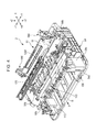
- Fig. 4 is an exploded perspective view illustrating the internal structure of the printer unit 2 and the arrangement route for the tube 120.
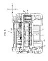
- Fig. 5 is a top view illustrating the internal structure of the printer unit 2 and the arrangement route for the tube 120.
- the apparatus frame 64 is a frame supporting each portion of the printer unit 2, and is configured to have integrally molded resins.
- the apparatus frame 64 includes a base frame portion 64a, a symmetrical pair of side frame portions 64b, a symmetrical pair of front frame portions 64c and symmetrical pair of rear frame portions 64d.
- a symmetrical pair of the side frame portions 64b is erected at the base frame portion 64a and supports each configuring member of the transport unit 61 and the guide frame 71 at both sides.
- a symmetrical pair of the front frame portions 64c supports a front portion of the scanner unit 3 in a front portion of the base frame portion 64a, and supports the operation unit 63.
- a symmetrical pair of the rear frame portions 64d supports the printer unit 2 to be capable of opening/closing through the opening/closing unit 4, in a rear portion of the base frame portion 64a.
- a pair of the rear frame portions 64d is erected up to the outside of the apparatus housing 65 via a rear portion opening which is open at a rear portion of the apparatus housing 65.
- a pair of the rear frame portions 64d is formed from configuring members of the opening/closing unit 4 at the printer unit 2 side.
- a sheet discharge frame 101 supporting a guide roller 97 and an auxiliary roller 99 is arranged at a front portion of the side frame portions 64b.
- the auxiliary roller (roller) 99 is arranged opposing the sheet discharge roller 96.
- the sheet discharge frame (frame member) 101 is arranged forward (+ X direction) from and below (- Z direction) the carriage 81.
- the sheet discharge frame 101 is horizontally laid along the scanning direction (Y direction) of the carriage 81 between a pair of the side frame portions 64b.
- a relatively wide space (front inner space S) is formed between the sheet discharge frame 101 and the discharge port 100.
- the ink container 110 storing the black ink is arranged in the front inner space S (refer to Fig. 2 ).
- An ink containing amount of the ink container 110 is equal to or more than the ink containing amount of the ink cartridge adapter 84 and the ink cartridge 85.
- the ink container 110 is arranged at a left end of the front inner space S.
- a left end region is a region which is not overlapped with the transport route R of the recording sheet P. Therefore, even though the ink container 110 is arranged at the left end region of the front inner space S, there is no interference between the ink container 110 and the recording sheet P.
- the ink container 110 even though it is arranged at a right end, has the same result.
- the tubes 120 are arranged (tube-laid) for supplying the ink contained in the ink container 110 toward the ink cartridge adapter 84 between the ink container 110 and the ink cartridge adapter 84.
- the tubes (liquid supply tube) 120 are formed from one tube 121 supplying the black ink.
- the tube 120 is fixed to a tube fixing member 170 attached to the apparatus housing 65 so as to be laid across the upper surface opening 10 between the ink container 110 and the ink cartridge adapter 84.
- a region between the tube fixing member 170 and the ink cartridge adapter 84 becomes a movable region 120F which is subjected to flexion deformity in association with a scanning movement of the carriage 81.
- the tube fixing member 170 is a long flat plate shaped member extending in a left and right direction (refer to Fig. 4 ).
- the tube fixing member 170 is attached to the apparatus housing 65 so as to horizontally cross over the upper surface opening 10 along the scanning direction (Y direction).
- the tube fixing member 170 is attached to the apparatus housing 65 so as to be laid across the left side and the right side of the apparatus housing 65 by pinching the upper surface opening 10. Both ends of the tube fixing member 170 are fixed to the apparatus housing 65 using an adhesive or adhesive tape.
- the tube 120 formed from the tube 121 is fixed to the center of the tube fixing member 170 in the left and right direction.
- the arrangement route (tube laying route) of the tubes 120 will be described along a direction (ink flowing direction) from the ink container 110 toward the ink cartridge adapter 84 (to be described in order of Figs. 2 and 5 ).
- the tubes 120 are laid across from the ink container 110 toward the center of the tube fixing member 170 in the left and right direction.
- the tubes 120 are fastened and fixed to the center of the tube fixing member 170 in the left and right direction using a fastening band and the like.
- the tubes 120 are once arranged toward the + Y direction after being fixed to the tube fixing member 170. Then, the tube 120 is folded back in a U shape and is inverted from the + Y direction to the - Y direction. The tubes 120 are vertically folded back in the U shape.
- the tubes 120 after being inverted in the - Y direction, are fixed on the upper surface of four ink cartridge adapters 84 contained in the carriage 81.
- the tubes 120 are fixed on the upper surface of the ink cartridge adapters 84 using the fastening band and the like. Then, the tubes 120 are connected to the respective ink cartridge adapters 84.
- a region bent in the U shape becomes the movable region 120F which is subjected to flexion deformity in association with the scanning movement of the carriage 81.
- a length of the movable region 120F is adjusted so as not to interfere with the scanning movement of the carriage 81.
- Fig. 6 is a view illustrating a modification example for arranging ink containers 110.
- the ink containers 110 (ink container 111 to 114) storing the black, cyan, magenta and yellow ink may be arranged partially or entirely.
- the tubes 120 are arranged (tube-laid) between the four ink cartridge adapters 84 and the ink containers 110 (four ink containers 111 to 114).
- the ink container 111 is arranged at a left end of the front inner space S.
- the ink container 112 is arranged at a right end of the front inner space S.
- the ink containers 113 and 114 are arranged on a front side which is an outside region of the printer unit 2.
- a combination of the ink containers 110 contained in the front inner space S with the ink containers 110 arranged outside the printer unit 2 can be modified. All the ink containers 110 may be contained in the front inner space S.
- the tubes 121 and 121 connected to the ink containers 111 and 112 are respectively laid across toward the center of the tube fixing member 170 in the left and right direction.
- the tubes 123 and 124 connected to the ink containers 113 and 114 are respectively laid across toward the center of the tube fixing member 170 in the left and right direction after passing through the discharge port 100.
- the tubes 120 formed from the four tubes 121 to 124 are fixed to the center of the tube fixing member 170 in the left and right direction.
- the front inner space S of the printer unit 2 contains the ink containers 110.
- the ink containers 110 Since a distance is short between the ink containers 110 and the carriage 81, it is possible to easily secure the arrangement route of the tubes 120, whereby optimizing the arrangement route of the tubes 120.
- the ink container may be arranged outside the printer unit 2 only.
- Fig. 12 is a top view of the printer unit 2 and an ink container 300.
- the ink container 300 containing the black ink is arranged outside the printer unit 2.
- the ink containing amount of the ink container 300 is equal to or greater than the ink containing amount of the ink cartridge adapter 84 and the ink cartridge 85.
- the tubes 120 are fixed to the fixing member 170 between the ink container 300 and the ink cartridge adapter 84. Within the tubes 120, a region between the tube fixing member 170 and the ink cartridge adapter 84 becomes the movable region 120F which is subjected to flexion deformation in association with the scanning movement of the carriage 81.
- a multi-function printer 201 according to a second embodiment of the invention will be described.
- the same reference numerals are given to the same configurations and members as those of the multi-function printer according to the first embodiment, and the description thereof will not be repeated.
- Fig. 7 is an exploded perspective view illustrating the internal structure of the multi-function printer 201 and the arrangement route for the tubes 120 according to the second embodiment of the invention.
- an ink mounting table 210 is arranged where four of the ink containers 110 (ink containers 111 to 114) are mounted.
- the ink mounting table 210 has a long flat plate section 211 extending in the left and right direction and two leg portions 212 arranged across both ends of the flat plate section 211 in the left and right direction, and is formed using a bending process of sheet metal or the like.
- a longitudinal direction of the flat plate section 211 is substantially coincident with a length of the front inner space S in the left and right direction.
- the length (height) of the two leg portions 212 is approximately 5 mm to 10 mm, for example.
- the ink mounting table 210 is arranged such that the flat plate section 211 horizontally crosses the front inner space S along the scanning direction (Y direction) and the two leg portions 212 faces downward.
- a space between a bottom surface of the front inner space S and the flat plate section 211 is the transport route R of the recording sheet P.
- the ink mounting table 210 is arranged across the transport route R of the recording sheet P.
- the four ink containers 110 are mounted on an upper surface of the flat plate section 211.
- the four ink containers 110 are arranged at a region overlapped with the transport route R of the recording sheet P when viewed from the top (viewed from the + Z direction).
- the four ink cartridge adapters 84 are contained in the carriage 81 to be attachable and detachable.
- the tubes 120 (four tubes 121 to 124) are arranged (tube-laid) between the four ink cartridge adapters 84 and the ink containers 110 (four ink containers 111 to 114).
- the four ink containers 111 to 114 are arranged in parallel so as to be overlapped with one another toward the left and right direction, on the upper surface of the flat plate section 211.
- the four ink containers 111 to 114 are overlapped with one another in a thickness direction thereof.
- the four ink containers 111 to 114 are fastened using the fastening band and the like.
- the tubes 120 (tubes 121 to 124) connected to the four ink containers 111 to 114 are respectively and directly laid across toward the ink cartridge adapters 84 of the carriage 81.
- the tubes 120 are fixed on the ink cartridge adapters 84 using the fastening band. Then, the tubes 120 are respectively connected to the ink cartridge adapters 84.
- All regions of the tubes 120 become the movable region 120F which is subjected to flexion deformation in association with the scanning movement of the carriage 81.
- the length of the movable region 120F is adjusted so as not to interfere with the scanning movement of the carriage 81.
- Fig. 8 is a view illustrating a modification example for arranging the ink containers 110.
- (a) is a view illustrating a case where the ink containers 110 are arranged by being vertically overlapped.
- (b) is a view illustrating a case where the ink containers 110 are arranged by being overlapped in the front/rear direction.
- (c) is a view illustrating a case where the ink containers 110 are arranged by being overlapped (in parallel) toward the left and right direction in a direction different from the thickness direction.
- the ink containers 110 (four ink containers 111 to 114) can be arranged in parallel so as to be overlapped with one another, vertically, toward the front/rear direction or toward the left and right direction, on the upper surface of the flat plate section 211.
- the arrangement direction and the overlapped direction may be appropriately set.
- Fig. 9 is a view illustrating an ink mounting table 220.
- the ink mounting table 220 is a modification example of the ink mounting table 210. In place of the ink mounting table 210, the ink mounting table 220 may be used.
- the ink mounting table 220 has a flat plate section 221 which has the same shape as the flat plate section 211 of the ink mounting table 210.
- the ink mounting table 210 there are provided two suspending sections 222 which are bent upward at both ends of the flat plate section 211 in the left and right direction.
- the two suspending sections 222 have a shape hooked by edges of the upper surface opening 10 which exposes the front inner space S.
- the ink mounting table 220 is arranged such that the flat plate section 221 horizontally crosses the front inner space S along the scanning direction (Y direction) and the two suspending sections 222 face upward. Since the two suspending sections 222 are hooked by the edges of the upper surface opening 10, the transport route R of the recording sheet P is secured between the flat plate section 221 and the bottom surface of the front inner space S.
- the four ink containers 110 are mounted on the upper surface of the flat plate section 221.
- the four ink containers 110 are arranged at the region overlapped with the transport route R of the recording sheet P, when viewed from the top (viewed from the + Z direction).
- the same advantageous effects as the multi-function printer 1 according to the first embodiment may be achieved. That is, the front inner space S of the printer unit 2 contains the ink containers 110. Thus, it is not necessary to perform additional processing on the printer unit 2. Since the distance is short between the ink containers 110 and the carriage 81, it is possible to easily secure the arrangement route of the tubes 120, whereby optimizing the arrangement route of the tubes 120.
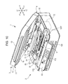
- Fig. 10 is a view illustrating a state where an operation unit 63 is tilted forward.
- the multi-function printers 1 and 201 enable the operation unit 63 to be tilted forward.
- a tilting mechanism (not illustrated) for tilting the operation unit 63 forward is disposed at a rear surface side (rearward) of the operation unit 63.
- the operation unit 63 and the tilting mechanism are disposed above the discharge port 100. Accordingly, in a case where the operation unit 63 is tilted forward, the front inner space S becomes wider compared to a case where the operation unit 63 is in a vertical state.
- the operation unit 63 is fixed by being tilted forward.
- the largest tilting angle of the operation unit 63 is ensured by causing the tilting mechanism not to be operable.
- Fig. 11 is a view illustrating an operation unit 66 arranged on the scanner unit 3.
- the multi-function printers 1 and 201 may be provided with an operation unit 66 arranged on the scanner unit 3 in place of the operation unit 63 arranged to be capable of tilting with respect to the printer unit 2.
- the operation unit 66 arranged on the scanner unit 3 cannot be tilted with respect to the scanner unit 3.
- the operation unit 63 is in the vertical state.
- the operation unit 66 When the operation unit 66 is used, it is not necessary to have the tilting mechanism for tilting the operation unit 66 forward. Therefore, as compared to when using the operation unit 63, the front inner space S becomes wider.
- the number of the ink containers 110 is not limited to four and the number of the tubes 120 is not limited to four.
- the number of the ink containers 110 may be six and the number of the tubes 120 may be six.
- the carriage 81 may not allow the ink cartridge adapter 84 to be mounted thereon, and may be configured such that the ink is directly supplied from the ink containers 110 via the tubes 120.
- the apparatus having the ink containers 110 is not limited to the liquid ejecting apparatus, and may be an apparatus consuming the liquid.
- the liquid ejecting apparatus ejecting the liquid such as the ink has been described, but may be applied to the liquid ejecting apparatus ejecting or discharging other liquid except for the ink.
- the liquid which the liquid ejecting apparatus can eject includes a liquid body where functional material particles are dispersed or dissolved, and a liquid body in a gel.
- the liquid ejected from the liquid ejecting apparatus is not limited to the ink only, but is also applicable to the liquid corresponding to particular uses.
Landscapes
- Ink Jet (AREA)
Abstract
Description
- The present invention relates to a liquid ejecting apparatus which ejects a liquid onto a recording medium from a liquid ejecting head mounted on a carriage.
- An ink jet printer has been widely known as a liquid ejecting apparatus which ejects a liquid onto a recording medium from a liquid ejecting head.
- The inkjet printer includes a carriage and a recording head mounted on the carriage. The ink jet printer performs printing on a recording sheet by ejecting an ink (liquid) from a nozzle formed on the recording head while moving the carriage to perform scanning with respect to the recording sheet (recording medium).
- The ink jet printer includes one in which an ink cartridge supplying the ink to the recording head is mounted on the carriage (on-carriage type). The ink cartridge is detachably attached to the carriage.
- In the on-carriage type ink jet printer, there is a limit on the capacity of the ink in the ink cartridge. Frequent replacement of the ink cartridge is required when attempting to perform a relatively large volume of printing, which causes increased running cost.
- An apparatus has been proposed in which a large size ink tank is arranged outside the ink jet printer and the ink is supplied from the ink tank toward the carriage. In place of the ink cartridge, an attachment is mounted on the carriage. The ink is supplied from the ink tank to the attachment via a tube. This enables a large volume of printing (refer to Patent Literature 1).
- PTL 1: Chinese Examined Utility Model Registration Application Publication No.
2825289 - In the technology disclosed in
PTL 1, a large size ink tank is arranged laterally outside of an ink jet printer main body for all available colors. A tube is laid across a carriage from a side portion of the ink jet printer main body. - In a case of arranging the ink tank outside the ink jet printer main body, it is necessary for the ink jet printer main body to secure a route for the tube by performing an additional process. Therefore, there is a problem in that defects are likely to occur in the ink jet printer main body. In addition, when arranging all the colors outside the main body, there is a problem in that it is necessary for a user who rarely performs color printing to have a large space outside the main body as well.
- The invention, when additionally arranging the ink tank for the ink jet printer main body, aims to optimize a tube arrangement route arranged between the ink tank and the carriage as a first object, and when a large size ink tank is prepared for black color only, further aims to optimize the tube arrangement route for the user who rarely performs the color printing as a second object.
- A liquid ejecting apparatus according to the invention includes a liquid ejecting apparatus main body ejecting a liquid onto a recording medium from a liquid ejecting head mounted on a carriage; and a liquid supply tube that introduces the liquid supplied from a liquid containing body which contains the liquid to the liquid ejecting head, having a transformable moving unit which is transformed following the movement of the liquid ejecting head, in which an inner space is provided which is formed from a discharge port including a region where the recording medium is discharged, and the liquid containing body is arranged in the inner space.
- The discharge port is configured to have a sheet discharge region and a space other than the sheet discharge region.
- The liquid containing body is arranged in a region overlapped with a transport route of the recording medium.
- The liquid ejecting apparatus further includes a tube fixing member laid along a scanning direction of the liquid ejecting head, in which a portion of the liquid supply tube is fixed to the tube fixing member, and the liquid supply tube is laid across the tube fixing member and the carriage.
- The tube fixing member is a member with a flat plate shape.
- The liquid ejecting apparatus further includes an ink mounting table having a flat plate section arranged above the transport route of the recording medium, in which the liquid containing body is placed on the flat plate section.
- The ink mounting table has leg portions supporting the flat plate section at both end sides in the scanning direction of the carriage, and the ink mounting table is arranged across the sheet discharge region from the region other than the sheet discharge region.
- The inner space is exposed from an upper surface opening of an apparatus housing which covers the liquid ejecting apparatus main body, at both end sides in the scanning direction of the carriage, the ink mounting table has a suspending section that suspends the flat plate section from the upper surface opening to the inner space, and the ink mounting table is arranged by suspending the sheet discharge region from the region other than the sheet discharge region.
- A plurality of the liquid containing bodies is provided, and a plurality of the liquid containing bodies is arranged along the scanning direction of the carriage.
- A plurality of the liquid containing bodies is provided, and a plurality of the liquid containing bodies is arranged along the transport direction.
- A plurality of the liquid containing bodies is provided, and a plurality of the liquid containing bodies is arranged along a vertical direction.
- A plurality of the liquid containing bodies is provided, a portion of a plurality of the liquid containing bodies is arranged in the inner space, and remaining portion of the liquid containing bodies is arranged outside the liquid ejecting apparatus main body.
- The liquid ejecting apparatus further includes an operation unit having a tilting mechanism on a front surface at the discharge port side of the liquid ejecting apparatus main body, in which the operation unit is fixed in a tilted state.
- The liquid ejecting apparatus further includes an operation unit on a front surface at the discharge port side of the liquid ejecting apparatus main body, in which the operation unit is provided with a cover body arranged above the liquid ejecting apparatus main body.
- An image reader reading out an image of the recording medium is arranged to be closely mountable above the liquid ejecting apparatus main body, and the inner space is formed on a region overlapped with the image reader.
- A liquid ejecting apparatus includes a carriage reciprocating, being provided with a liquid ejecting head ejecting a liquid onto a recording medium; a liquid ejecting apparatus main body containing the carriage; and a liquid containing body containing the liquid supplied to the liquid ejecting head, communicating with the liquid ejecting head via a liquid tube, in which the carriage includes an adapter to which an opposite side of the liquid tube to the liquid containing body is connected and which communicates with the liquid ejecting head, and a liquid container storing the liquid to be supplied to the liquid ejecting head.
- The liquid containing body is mounted on the inner space inside the liquid ejecting apparatus main body.
- The liquid containing body is mounted on the outside of the liquid ejecting apparatus main body.
-
- [
Fig. 1] Fig. 1 is an external perspective view illustrating amulti-function printer 1 according to an embodiment of the invention. - [
Fig. 2] Fig. 2 is a perspective view illustrating themulti-function printer 1 when ascanner unit 3 is in an open state. - [
Fig. 3] Fig. 3 is a cross-sectional view in a side view, illustrating an internal structure of aprinter unit 2 and an arrangement route for atube 120. - [
Fig. 4] Fig. 4 is an exploded perspective view illustrating the internal structure of theprinter unit 2 and the arrangement route for thetube 120. - [
Fig. 5] Fig. 5 is a top view illustrating the internal structure of theprinter unit 2 and the arrangement route for thetube 120. - [
Fig. 6] Fig. 6 is a view illustrating a modification example for arrangingink containers 110. - [
Fig. 7] Fig. 7 is an exploded perspective view illustrating the internal structure of amulti-function printer 201 according to a second embodiment and the arrangement route for thetube 120. - [
Fig. 8] Fig. 8 is a view illustrating a modification example for arranging theink container 110. - [
Fig. 9] Fig. 9 is a view illustrating an ink mounting table 220. - [
Fig. 10] Fig. 10 is a view illustrating a state where anoperation unit 63 is tilted forward. - [
Fig. 11] Fig. 11 is a view illustrating anoperation unit 66 arranged on thescanner unit 3. - [
Fig. 12] Fig. 12 is a top view of theprinter unit 2 and anink container 300. Description of Embodiments - A
multi-function printer 1 according to a first embodiment of the invention will be described. - Hereinafter, in each drawing, a transport direction (sub-scanning) of a recording sheet P represents an X direction, a scanning direction (horizontal direction) of a
carriage 81 represents a Y direction and a vertical direction represents a Z direction. - For convenience, a downstream side (+ X direction) in the transport direction of the recording sheet P (recording medium) is referred to as forward and an upstream side (- X direction) is referred to as rearward. In the Y direction, the + Y direction is referred to as a left side and the - Y direction is referred to as a right side. In the Z direction, the + Z direction is referred to as upward and the -Z direction is referred to as downward.
-
Fig. 1 is a perspective appearance view illustrating themulti-function printer 1 according to the first embodiment of the invention.Fig. 2 is a perspective view illustrating the multi-function printer when ascanner unit 3 is in an open state. - The multi-function printer (liquid ejecting apparatus) 1 integrally includes a
printer unit 2 which is an apparatus main body, and ascanner unit 3 which is an upper unit arranged above theprinter unit 2. - As illustrated in
Fig. 2 , themulti-function printer 1 includes an ink container (liquid containing body) 110 inside (front inside space S) theprinter unit 2. - The
scanner unit 3 is pivotally supported by theprinter unit 2 through an opening/closing unit 4 at a rear end portion, and covers an upper section of theprinter unit 2 to be capable of opening/closing. - As illustrated in
Fig. 2 , if thescanner unit 3 is raised in a pivoting direction, an upper surface opening 10 of theprinter unit 2 is exposed. This exposes the inside of theprinter unit 2 from theupper surface opening 10. - On the other hand, if the
scanner unit 3 is pulled down in the pivoting direction and mounted on theprinter unit 2, thescanner unit 3 closes theupper surface opening 10. - In this manner, if the
scanner unit 3 is raised and the upper surface opening 10 is exposed, a paper jam and the like may be resolved. - The
scanner unit 3 includes anupper frame 11 made of resins, an image reader (not illustrated) contained in theupper frame 11 and anupper cover 13 pivotally supported by an upper portion of theupper frame 11. - Configuring members of the
scanner unit 3 side of the opening/closing unit 4 are disposed at a rear end portion of theupper frame 11. - The
upper frame 11 includes a box typelower case 16 containing the image reader (not illustrated), and anupper case 17 covering a top side of thelower case 16. - A manuscript mounting plate made of glass is widely arranged on the upper case 17 (not illustrated). A reading medium whose reading surface faces downward is mounted on the manuscript mounting plate.
- The image reader (not illustrated) contained in the
lower case 16 includes a line sensor type sensor unit (not illustrated). The sensor unit has an image sensor (sensor portion) which is a Charge Coupled Device (CCD) type line sensor extending in the X direction, and reciprocates in the Y direction. This enables the image of the reading medium (manuscript) to be read on the manuscript mounting plate. - As the image sensor, a Complementary Metal Oxide Semiconductor (CMOS) type line sensor may be used.
- The printer unit (liquid ejecting apparatus main body) 2 includes a
transport unit 61 transporting a sheet of the recording sheet P along a transport route R, aprinting unit 62 arranged above the transport route R, performing a printing process on the recording sheet P by way of an ink jet method, a paneltype operation unit 63 arranged on a front surface, anapparatus frame 64 on which thetransport unit 61, theprinting unit 62 and theoperation unit 63 are mounted, and anapparatus housing 65 covering these. -
Fig. 3 is a cross-sectional view in a side view, illustrating an internal structure of theprinter unit 2 and an arrangement route for atube 120. - The
printing unit 62 includes aguide frame 71 made of sheet metal, supporting theapparatus frame 64 and fully extending to a width in the Y direction, acarriage unit 72 supported by theguide frame 71 to freely reciprocate, and a carriage moving mechanism 73 (refer toFig. 2 ) allowing thecarriage unit 72 to reciprocate along theguide frame 71. - The
carriage unit 72 includes a box shapedcarriage 81 supported by theguide frame 71 to freely reciprocate through anengagement slider portion 81a, anink jet head 83 integrally incorporated on a lower surface of thecarriage 81, and four ink cartridges (ink cartridge 85 with oneink cartridge adapter 84 and three liquid containers) contained in thecarriage 81 to be attachable and detachable. - The ink jet head (liquid ejecting head) 83 has four nozzle rows (not illustrated) ejecting four colors of ink drops. Four cartridges (
ink cartridge adapter 84 and ink cartridge 85) storing the four colors of ink are mounted on thecarriage 81. Four cartridges (ink cartridge adapter 84 and ink cartridge 85) are directly connected to an upper surface side of theink jet head 83. - The
ink cartridge adapter 84 is supplied with a black ink from an ink container 110 (to be described later). Threeink cartridges 85 store cyan, magenta and yellow ink. - The
transport unit 61 includes a movabletype sheet tray 91 setting the recording sheet in a right alignment manner, aseparation roller 92 which sends separated recording sheets P one by one by separating the recording sheets P from thesheet tray 91, afeed roller 93 located downstream from theseparation roller 92 and sending the recording sheet P to theprinting unit 62 along the transport route R, amedium regulating member 95 located downstream from thefeed roller 93 and opposing theink jet head 83, a serrated guide roller 97 located downstream from themedium regulating member 95, and asheet discharge roller 96 located downstream from the guide roller 97 and sending the recording sheet P from a discharge port 100 (refer toFig. 2 ). - The
medium regulating member 95 is equivalent to a so-called platen. - The recording sheet P sent from the
sheet tray 91 by theseparation roller 92 is intermittently fed toward thesheet discharge roller 96 in the X direction over themedium regulating member 95 by the feed roller 93 (sub-scanning). - In synchronization with this intermittent feeding, the
carriage unit 72, reciprocating in the X direction, selectively ejects the ink (main scanning) to perform desired printing. - A leading edge of the recording sheet P reaching the guide roller 97 over the
medium regulating member 95 is subjected to correction of a dished state using the guide roller 97 so as to be sent to thesheet discharge roller 96. - In this manner, the printing completed recording sheet P is sent forward from the
discharge port 100 by thesheet discharge roller 96. -
Fig. 4 is an exploded perspective view illustrating the internal structure of theprinter unit 2 and the arrangement route for thetube 120. -
Fig. 5 is a top view illustrating the internal structure of theprinter unit 2 and the arrangement route for thetube 120. - The
apparatus frame 64 is a frame supporting each portion of theprinter unit 2, and is configured to have integrally molded resins. - The
apparatus frame 64 includes abase frame portion 64a, a symmetrical pair ofside frame portions 64b, a symmetrical pair offront frame portions 64c and symmetrical pair ofrear frame portions 64d. - A symmetrical pair of the
side frame portions 64b is erected at thebase frame portion 64a and supports each configuring member of thetransport unit 61 and theguide frame 71 at both sides. - A symmetrical pair of the
front frame portions 64c supports a front portion of thescanner unit 3 in a front portion of thebase frame portion 64a, and supports theoperation unit 63. - A symmetrical pair of the
rear frame portions 64d supports theprinter unit 2 to be capable of opening/closing through the opening/closing unit 4, in a rear portion of thebase frame portion 64a. - A pair of the
rear frame portions 64d is erected up to the outside of theapparatus housing 65 via a rear portion opening which is open at a rear portion of theapparatus housing 65. A pair of therear frame portions 64d is formed from configuring members of the opening/closing unit 4 at theprinter unit 2 side. - A
sheet discharge frame 101 supporting a guide roller 97 and anauxiliary roller 99 is arranged at a front portion of theside frame portions 64b. The auxiliary roller (roller) 99 is arranged opposing thesheet discharge roller 96. - The sheet discharge frame (frame member) 101 is arranged forward (+ X direction) from and below (- Z direction) the
carriage 81. Thesheet discharge frame 101 is horizontally laid along the scanning direction (Y direction) of thecarriage 81 between a pair of theside frame portions 64b. - A relatively wide space (front inner space S) is formed between the
sheet discharge frame 101 and thedischarge port 100. - The
ink container 110 storing the black ink is arranged in the front inner space S (refer toFig. 2 ). An ink containing amount of theink container 110 is equal to or more than the ink containing amount of theink cartridge adapter 84 and theink cartridge 85. - The
ink container 110 is arranged at a left end of the front inner space S. Within the front inner space S, a left end region is a region which is not overlapped with the transport route R of the recording sheet P. Therefore, even though theink container 110 is arranged at the left end region of the front inner space S, there is no interference between theink container 110 and the recording sheet P. - The
ink container 110, even though it is arranged at a right end, has the same result. - The
tubes 120 are arranged (tube-laid) for supplying the ink contained in theink container 110 toward theink cartridge adapter 84 between theink container 110 and theink cartridge adapter 84. The tubes (liquid supply tube) 120 are formed from onetube 121 supplying the black ink. - The
tube 120 is fixed to atube fixing member 170 attached to theapparatus housing 65 so as to be laid across the upper surface opening 10 between theink container 110 and theink cartridge adapter 84. Within thetube 120, a region between thetube fixing member 170 and theink cartridge adapter 84 becomes amovable region 120F which is subjected to flexion deformity in association with a scanning movement of thecarriage 81. - The
tube fixing member 170 is a long flat plate shaped member extending in a left and right direction (refer toFig. 4 ). Thetube fixing member 170 is attached to theapparatus housing 65 so as to horizontally cross over the upper surface opening 10 along the scanning direction (Y direction). Thetube fixing member 170 is attached to theapparatus housing 65 so as to be laid across the left side and the right side of theapparatus housing 65 by pinching theupper surface opening 10. Both ends of thetube fixing member 170 are fixed to theapparatus housing 65 using an adhesive or adhesive tape. - The
tube 120 formed from thetube 121 is fixed to the center of thetube fixing member 170 in the left and right direction. - The arrangement route (tube laying route) of the
tubes 120 will be described along a direction (ink flowing direction) from theink container 110 toward the ink cartridge adapter 84 (to be described in order ofFigs. 2 and5 ). - First, as illustrated in
Fig. 2 , thetubes 120 are laid across from theink container 110 toward the center of thetube fixing member 170 in the left and right direction. Thetubes 120 are fastened and fixed to the center of thetube fixing member 170 in the left and right direction using a fastening band and the like. - Furthermore, as illustrated in
Fig. 5 , thetubes 120 are once arranged toward the + Y direction after being fixed to thetube fixing member 170. Then, thetube 120 is folded back in a U shape and is inverted from the + Y direction to the - Y direction. Thetubes 120 are vertically folded back in the U shape. - The
tubes 120, after being inverted in the - Y direction, are fixed on the upper surface of fourink cartridge adapters 84 contained in thecarriage 81. Thetubes 120 are fixed on the upper surface of theink cartridge adapters 84 using the fastening band and the like. Then, thetubes 120 are connected to the respectiveink cartridge adapters 84. - Within the
tubes 120, a region bent in the U shape becomes themovable region 120F which is subjected to flexion deformity in association with the scanning movement of thecarriage 81. A length of themovable region 120F is adjusted so as not to interfere with the scanning movement of thecarriage 81. -
Fig. 6 is a view illustrating a modification example for arrangingink containers 110. - In the front inner space S, the ink containers 110 (
ink container 111 to 114) storing the black, cyan, magenta and yellow ink may be arranged partially or entirely. - Four
ink cartridge adapters 84 are contained in thecarriage 81 to be attachable and detachable. The tubes 120 (fourtubes 121 to 124) are arranged (tube-laid) between the fourink cartridge adapters 84 and the ink containers 110 (fourink containers 111 to 114). - In the
ink containers 110, theink container 111 is arranged at a left end of the front inner space S. Theink container 112 is arranged at a right end of the front inner space S. Theink containers printer unit 2. - A combination of the
ink containers 110 contained in the front inner space S with theink containers 110 arranged outside theprinter unit 2 can be modified. All theink containers 110 may be contained in the front inner space S. - The
tubes ink containers tube fixing member 170 in the left and right direction. Thetubes ink containers tube fixing member 170 in the left and right direction after passing through thedischarge port 100. - The
tubes 120 formed from the fourtubes 121 to 124 are fixed to the center of thetube fixing member 170 in the left and right direction. - As described above, in the
multi-function printer 1 according to the first embodiment, the front inner space S of theprinter unit 2 contains theink containers 110. Thus, it is hardly necessary to perform additional processing on theprinter unit 2. Since a distance is short between theink containers 110 and thecarriage 81, it is possible to easily secure the arrangement route of thetubes 120, whereby optimizing the arrangement route of thetubes 120. - Without arranging the ink container inside the
apparatus housing 65, the ink container may be arranged outside theprinter unit 2 only.Fig. 12 is a top view of theprinter unit 2 and anink container 300. Theink container 300 containing the black ink is arranged outside theprinter unit 2. The ink containing amount of theink container 300 is equal to or greater than the ink containing amount of theink cartridge adapter 84 and theink cartridge 85. - The
tubes 120 are fixed to the fixingmember 170 between theink container 300 and theink cartridge adapter 84. Within thetubes 120, a region between thetube fixing member 170 and theink cartridge adapter 84 becomes themovable region 120F which is subjected to flexion deformation in association with the scanning movement of thecarriage 81. - A
multi-function printer 201 according to a second embodiment of the invention will be described. The same reference numerals are given to the same configurations and members as those of the multi-function printer according to the first embodiment, and the description thereof will not be repeated. -
Fig. 7 is an exploded perspective view illustrating the internal structure of themulti-function printer 201 and the arrangement route for thetubes 120 according to the second embodiment of the invention. - In the front inner space S, an ink mounting table 210 is arranged where four of the ink containers 110 (
ink containers 111 to 114) are mounted. - The ink mounting table 210 has a long
flat plate section 211 extending in the left and right direction and twoleg portions 212 arranged across both ends of theflat plate section 211 in the left and right direction, and is formed using a bending process of sheet metal or the like. - A longitudinal direction of the
flat plate section 211 is substantially coincident with a length of the front inner space S in the left and right direction. The length (height) of the twoleg portions 212 is approximately 5 mm to 10 mm, for example. - The ink mounting table 210 is arranged such that the
flat plate section 211 horizontally crosses the front inner space S along the scanning direction (Y direction) and the twoleg portions 212 faces downward. - A space between a bottom surface of the front inner space S and the
flat plate section 211 is the transport route R of the recording sheet P. The ink mounting table 210 is arranged across the transport route R of the recording sheet P. - The four
ink containers 110 are mounted on an upper surface of theflat plate section 211. The fourink containers 110 are arranged at a region overlapped with the transport route R of the recording sheet P when viewed from the top (viewed from the + Z direction). - The four
ink cartridge adapters 84 are contained in thecarriage 81 to be attachable and detachable. The tubes 120 (fourtubes 121 to 124) are arranged (tube-laid) between the fourink cartridge adapters 84 and the ink containers 110 (fourink containers 111 to 114). - The four
ink containers 111 to 114 are arranged in parallel so as to be overlapped with one another toward the left and right direction, on the upper surface of theflat plate section 211. The fourink containers 111 to 114 are overlapped with one another in a thickness direction thereof. The fourink containers 111 to 114 are fastened using the fastening band and the like. - The tubes 120 (
tubes 121 to 124) connected to the fourink containers 111 to 114 are respectively and directly laid across toward theink cartridge adapters 84 of thecarriage 81. Thetubes 120 are fixed on theink cartridge adapters 84 using the fastening band. Then, thetubes 120 are respectively connected to theink cartridge adapters 84. - All regions of the
tubes 120 become themovable region 120F which is subjected to flexion deformation in association with the scanning movement of thecarriage 81. The length of themovable region 120F is adjusted so as not to interfere with the scanning movement of thecarriage 81. -
Fig. 8 is a view illustrating a modification example for arranging theink containers 110. (a) is a view illustrating a case where theink containers 110 are arranged by being vertically overlapped. (b) is a view illustrating a case where theink containers 110 are arranged by being overlapped in the front/rear direction. (c) is a view illustrating a case where theink containers 110 are arranged by being overlapped (in parallel) toward the left and right direction in a direction different from the thickness direction. - The ink containers 110 (four
ink containers 111 to 114) can be arranged in parallel so as to be overlapped with one another, vertically, toward the front/rear direction or toward the left and right direction, on the upper surface of theflat plate section 211. Depending on the volume of the fourink containers 111 to 114, the arrangement direction and the overlapped direction may be appropriately set. -
Fig. 9 is a view illustrating an ink mounting table 220. - The ink mounting table 220 is a modification example of the ink mounting table 210. In place of the ink mounting table 210, the ink mounting table 220 may be used.
- The ink mounting table 220 has a flat plate section 221 which has the same shape as the
flat plate section 211 of the ink mounting table 210. - In contrast, unlike the ink mounting table 210, there are provided two suspending
sections 222 which are bent upward at both ends of theflat plate section 211 in the left and right direction. The two suspendingsections 222 have a shape hooked by edges of the upper surface opening 10 which exposes the front inner space S. - The ink mounting table 220 is arranged such that the flat plate section 221 horizontally crosses the front inner space S along the scanning direction (Y direction) and the two suspending
sections 222 face upward. Since the two suspendingsections 222 are hooked by the edges of the upper surface opening 10, the transport route R of the recording sheet P is secured between the flat plate section 221 and the bottom surface of the front inner space S. - The four
ink containers 110 are mounted on the upper surface of the flat plate section 221. The fourink containers 110 are arranged at the region overlapped with the transport route R of the recording sheet P, when viewed from the top (viewed from the + Z direction). - As described above, in the
multi-function printer 201 according to the second embodiment as well, the same advantageous effects as themulti-function printer 1 according to the first embodiment may be achieved. That is, the front inner space S of theprinter unit 2 contains theink containers 110. Thus, it is not necessary to perform additional processing on theprinter unit 2. Since the distance is short between theink containers 110 and thecarriage 81, it is possible to easily secure the arrangement route of thetubes 120, whereby optimizing the arrangement route of thetubes 120. - Various shapes or combinations of the respective configuring members illustrated in the embodiments described above are merely an example, and various modifications can be made, based on design requirements within the range without departing from the gist of the invention.
-
Fig. 10 is a view illustrating a state where anoperation unit 63 is tilted forward. - The
multi-function printers operation unit 63 to be tilted forward. A tilting mechanism (not illustrated) for tilting theoperation unit 63 forward is disposed at a rear surface side (rearward) of theoperation unit 63. Theoperation unit 63 and the tilting mechanism are disposed above thedischarge port 100. Accordingly, in a case where theoperation unit 63 is tilted forward, the front inner space S becomes wider compared to a case where theoperation unit 63 is in a vertical state. - Therefore, in the
multi-function printers operation unit 63 is fixed by being tilted forward. The largest tilting angle of theoperation unit 63 is ensured by causing the tilting mechanism not to be operable. - This allows the front inner space S to be wider, and thereby enables
more ink containers 110 to be disposed. -
Fig. 11 is a view illustrating anoperation unit 66 arranged on thescanner unit 3. - The
multi-function printers operation unit 66 arranged on thescanner unit 3 in place of theoperation unit 63 arranged to be capable of tilting with respect to theprinter unit 2. - The
operation unit 66 arranged on thescanner unit 3 cannot be tilted with respect to thescanner unit 3. When thescanner unit 3 is closed, theoperation unit 63 is in the vertical state. - When the
operation unit 66 is used, it is not necessary to have the tilting mechanism for tilting theoperation unit 66 forward. Therefore, as compared to when using theoperation unit 63, the front inner space S becomes wider. - This allows the front inner space S to be wider, and thereby enables
more ink containers 110 to be disposed. - The number of the
ink containers 110 is not limited to four and the number of thetubes 120 is not limited to four. The number of theink containers 110 may be six and the number of thetubes 120 may be six. - The
carriage 81 may not allow theink cartridge adapter 84 to be mounted thereon, and may be configured such that the ink is directly supplied from theink containers 110 via thetubes 120. - The apparatus having the
ink containers 110 is not limited to the liquid ejecting apparatus, and may be an apparatus consuming the liquid. - By way of an example as the liquid ejecting apparatus, the liquid ejecting apparatus ejecting the liquid such as the ink has been described, but may be applied to the liquid ejecting apparatus ejecting or discharging other liquid except for the ink. The liquid which the liquid ejecting apparatus can eject includes a liquid body where functional material particles are dispersed or dissolved, and a liquid body in a gel.
- The liquid ejected from the liquid ejecting apparatus is not limited to the ink only, but is also applicable to the liquid corresponding to particular uses.
-
- 1, 201: multi-function printer (liquid ejecting apparatus)
- 2: printer unit (liquid ejecting apparatus main body)
- 3: scanner unit (cover body, image reader)
- 10: upper surface opening
- 63, 66: operation unit
- 81: carriage
- 83: inkjet head (liquid ejecting head)
- 84: ink cartridge adapter
- 100: discharge port
- 110, 300: ink container (liquid containing body)
- 120: tube (liquid supply tube)
- 170: tube fixing member
- 210: ink mounting table
- 211: flat plate section
- 212: leg portion
- 220: ink mounting table
- 221: flat plate section
- 222: suspending section
- P: recording sheet (recording medium)
- R: transport route
- S: front inner space (inner space)
Claims (18)
- A liquid ejecting apparatus comprising:a liquid ejecting apparatus main body ejecting a liquid onto a recording medium from a liquid ejecting head mounted on a carriage; anda liquid supply tube that introduces the liquid supplied from a liquid containing body which contains the liquid to the liquid ejecting head, having a transformable moving unit which is transformed following the movement of the liquid ejecting head,wherein an inner space is provided which is formed from a discharge port including a region where the recording medium is discharged, and the liquid containing body is arranged in the inner space.
- The liquid ejecting apparatus according to claim 1,
wherein the discharge port is formed from a sheet discharge region and a space other than the sheet discharge region. - The liquid ejecting apparatus according to claim 1,
wherein the liquid containing body is arranged in a region overlapped with a transport route of the recording medium. - The liquid ejecting apparatus according to claim 1, further comprising:a tube fixing member laid along a scanning direction of the liquid ejecting head,wherein a portion of the liquid supply tube is fixed to the tube fixing member, and the liquid supply tube is laid across between the tube fixing member and the carriage.
- The liquid ejecting apparatus according to claim 4,
wherein the tube fixing member is a member with a flat plate shape. - The liquid ejecting apparatus according to claim 1, further comprising:an ink mounting table having a flat plate section arranged above the transport route of the recording medium in the inner space,wherein the liquid containing body is mounted on the flat plate section.
- The liquid ejecting apparatus according to claim 6,
wherein the ink mounting table has leg portions supporting the flat plate section at both end sides in the scanning direction of the carriage, and
wherein the ink mounting table is arranged across the sheet discharge region from the region other than the sheet discharge region. - The liquid ejecting apparatus according to claim 6,
wherein the inner space is exposed from an upper surface opening of an apparatus housing which covers the liquid ejecting apparatus main body,
wherein at both end sides in the scanning direction of the carriage, the ink mounting table has a suspending section that suspends the flat plate section from the upper surface opening to the inner space, and
wherein the ink mounting table is arranged by suspending the sheet discharge region from the region other than the sheet discharge region. - The liquid ejecting apparatus according to claim 1,
wherein a plurality of the liquid containing bodies is provided, and a plurality of the liquid containing bodies is arranged along the scanning direction of the carriage. - The liquid ejecting apparatus according to claim 1,
wherein a plurality of the liquid containing bodies is provided, and a plurality of the liquid containing bodies is arranged along the transport direction of the recording medium. - The liquid ejecting apparatus according to claim 1,
wherein a plurality of the liquid containing bodies is provided, and a plurality of the liquid containing bodies is arranged along a vertical direction. - The liquid ejecting apparatus according to claim 1,
wherein a plurality of the liquid containing bodies is provided, a portion of a plurality of the liquid containing bodies is arranged in the inner space, and remaining portion of the liquid containing bodies is arranged outside the liquid ejecting apparatus main body. - The liquid ejecting apparatus according to claim 1, further comprising:an operation unit having a tilting mechanism on a front surface at the discharge port side of the liquid ejecting apparatus main body,wherein the operation unit is fixed in a tilted state.
- The liquid ejecting apparatus according to claim 1, further comprising:an operation unit on a front surface at the discharge port side of the liquid ejecting apparatus main body,wherein the operation unit is disposed in a cover body arranged above the liquid ejecting apparatus main body.
- The liquid ejecting apparatus according to claim 1,
wherein an image reader reading out an image of the recording medium is arranged to be closely mountable above the liquid ejecting apparatus main body, and
wherein the inner space is formed on a region overlapped with the image reader. - A liquid ejecting apparatus comprising:a carriage reciprocating, being provided with a liquid ejecting head ejecting a liquid onto a recording medium;a liquid ejecting apparatus main body containing the carriage; anda liquid containing body containing the liquid supplied to the liquid ejecting head, communicating with the liquid ejecting head via a liquid tube,wherein the carriage includes an adapter to which an opposite side of the liquid tube to the liquid containing body is connected and which communicates with the liquid ejecting head, and a liquid container storing the liquid to be supplied to the liquid ejecting head.
- The liquid ejecting apparatus according to claim 16,
wherein the liquid containing body is mounted on the inner space inside the liquid ejecting apparatus main body. - The liquid ejecting apparatus according to claim 16,
wherein the liquid containing body is mounted on the outside of the liquid ejecting apparatus main body.
Applications Claiming Priority (2)
| Application Number | Priority Date | Filing Date | Title |
|---|---|---|---|
| JP2012047697A JP6161869B2 (en) | 2012-03-05 | 2012-03-05 | Liquid ejector |
| PCT/JP2013/001285 WO2013132810A1 (en) | 2012-03-05 | 2013-03-01 | Liquid ejection device |
Publications (2)
| Publication Number | Publication Date |
|---|---|
| EP2823963A1 true EP2823963A1 (en) | 2015-01-14 |
| EP2823963A4 EP2823963A4 (en) | 2017-04-26 |
Family
ID=49116306
Family Applications (1)
| Application Number | Title | Priority Date | Filing Date |
|---|---|---|---|
| EP13757373.9A Ceased EP2823963A4 (en) | 2012-03-05 | 2013-03-01 | Liquid ejection device |
Country Status (8)
| Country | Link |
|---|---|
| US (3) | US9283765B2 (en) |
| EP (1) | EP2823963A4 (en) |
| JP (1) | JP6161869B2 (en) |
| CN (3) | CN104144790B (en) |
| IN (1) | IN2014DN05821A (en) |
| RU (2) | RU2693511C2 (en) |
| TW (1) | TWM466793U (en) |
| WO (1) | WO2013132810A1 (en) |
Families Citing this family (6)
| Publication number | Priority date | Publication date | Assignee | Title |
|---|---|---|---|---|
| JP6161869B2 (en) | 2012-03-05 | 2017-07-12 | セイコーエプソン株式会社 | Liquid ejector |
| JP6330331B2 (en) | 2014-01-14 | 2018-05-30 | セイコーエプソン株式会社 | Liquid container, liquid ejecting system, liquid ejecting apparatus |
| TWI644730B (en) * | 2014-02-05 | 2018-12-21 | 山保工業股份有限公司 | Liquid spray nozzle |
| JP6922362B2 (en) * | 2017-04-10 | 2021-08-18 | セイコーエプソン株式会社 | Printing device and control method of printing device |
| JP7143656B2 (en) * | 2018-07-13 | 2022-09-29 | ブラザー工業株式会社 | printer |
| JP7223255B2 (en) * | 2018-12-26 | 2023-02-16 | セイコーエプソン株式会社 | Inkjet printer, ink supply unit |
Family Cites Families (50)
| Publication number | Priority date | Publication date | Assignee | Title |
|---|---|---|---|---|
| EP0714778B1 (en) * | 1994-05-17 | 2000-03-22 | Seiko Epson Corporation | Ink jet recorder and method of cleaning recording head |
| US6170937B1 (en) * | 1997-01-21 | 2001-01-09 | Hewlett-Packard Company | Ink container refurbishment method |
| JP3376216B2 (en) * | 1995-07-18 | 2003-02-10 | キヤノン株式会社 | Image forming device |
| JPH10217496A (en) * | 1997-02-06 | 1998-08-18 | Citizen Watch Co Ltd | Ink jet recording device |
| US6233586B1 (en) * | 1998-04-01 | 2001-05-15 | International Business Machines Corp. | Federated searching of heterogeneous datastores using a federated query object |
| JP3768725B2 (en) * | 1998-06-15 | 2006-04-19 | キヤノン株式会社 | Inkjet recording device |
| JP3900798B2 (en) * | 2000-07-10 | 2007-04-04 | コニカミノルタホールディングス株式会社 | Inkjet head recovery device, inkjet image recording device |
| JP3818194B2 (en) * | 2002-03-28 | 2006-09-06 | ブラザー工業株式会社 | Recording device |
| US20030076391A1 (en) | 2001-10-24 | 2003-04-24 | Wilson John F. | Supply adaptor for an on-axis printer |
| JP2003200597A (en) * | 2001-10-25 | 2003-07-15 | Matsushita Electric Ind Co Ltd | Inkjet recording device |
| JP4196176B2 (en) | 2002-03-07 | 2008-12-17 | セイコーエプソン株式会社 | Optical disc ejection device and ink jet recording apparatus equipped with the ejection device |
| DE60201172T2 (en) * | 2002-03-28 | 2005-11-17 | Brother Kogyo K.K., Nagoya | Ink cartridge and method of making the same |
| JP2003326732A (en) | 2002-05-16 | 2003-11-19 | Canon Inc | Ink supply device |
| US6719414B2 (en) | 2002-07-31 | 2004-04-13 | Hewlett-Packard Development Company, Lp | Ink tube carrier for a printer, and method |
| CA2395836C (en) * | 2002-08-07 | 2007-12-04 | Per G. Akermalm | Expanded ink supply system for inkjet printers |
| US7008051B2 (en) * | 2002-10-10 | 2006-03-07 | Akermalm Per G | Expanded ink supply system for ink jet printers |
| JP2004345247A (en) * | 2003-05-22 | 2004-12-09 | Matsushita Electric Ind Co Ltd | Ink jet recording device |
| JP4635426B2 (en) * | 2003-10-22 | 2011-02-23 | ブラザー工業株式会社 | Image forming apparatus |
| US7303271B2 (en) * | 2003-10-24 | 2007-12-04 | Brother Kogyo Kabushiki Kaisha | Ink jet printer |
| US7712891B2 (en) * | 2003-12-26 | 2010-05-11 | Brother Kogyo Kabushiki Kaisha | Image-forming device |
| JP4595425B2 (en) * | 2004-07-28 | 2010-12-08 | ブラザー工業株式会社 | Recording device |
| CN100423940C (en) * | 2004-03-05 | 2008-10-08 | 兄弟工业株式会社 | image recording device |
| JP2006007678A (en) | 2004-06-29 | 2006-01-12 | Ricoh Co Ltd | Maintenance / recovery device for liquid ejection device and image forming apparatus |
| JP2006102985A (en) * | 2004-09-30 | 2006-04-20 | Seiko Epson Corp | Liquid ejector |
| JP2006110946A (en) * | 2004-10-18 | 2006-04-27 | Ricoh Co Ltd | Image forming apparatus |
| JP4613616B2 (en) | 2005-01-05 | 2011-01-19 | セイコーエプソン株式会社 | Liquid container module and liquid ejecting apparatus |
| JP4726155B2 (en) * | 2005-02-22 | 2011-07-20 | 株式会社リコー | Image forming apparatus |
| JP4725182B2 (en) | 2005-04-28 | 2011-07-13 | セイコーエプソン株式会社 | Method for manufacturing liquid supply system and liquid supply system |
| EP1880856B1 (en) * | 2005-05-13 | 2012-11-07 | Brother Kogyo Kabushiki Kaisha | Ink jet recording apparatus |
| CN2825289Y (en) | 2005-10-25 | 2006-10-11 | 珠海天威技术开发有限公司 | Connecting device for continuous ink-feeding system |
| JP2007152725A (en) * | 2005-12-05 | 2007-06-21 | Brother Ind Ltd | Inkjet printer recovery device |
| JP4569507B2 (en) * | 2006-03-31 | 2010-10-27 | ブラザー工業株式会社 | Inkjet recording device |
| US7385116B2 (en) * | 2006-04-28 | 2008-06-10 | Monsanto Technology Llc | Soybean variety 0240187 |
| JP4337855B2 (en) * | 2006-09-20 | 2009-09-30 | ブラザー工業株式会社 | Scanning device |
| JP5224754B2 (en) * | 2006-11-29 | 2013-07-03 | キヤノン株式会社 | Inkjet recording device |
| US7950764B2 (en) * | 2007-03-16 | 2011-05-31 | Seiko Epson Corporation | Pressure regulating mechanism and liquid ejecting apparatus |
| CN101541551B (en) * | 2007-03-19 | 2012-02-29 | 株式会社理光 | Ink-jet recording method and recorded matter |
| JP2008229974A (en) * | 2007-03-19 | 2008-10-02 | Brother Ind Ltd | Printer system, and master printer and slave printer used therefor |
| JP2008238787A (en) | 2007-03-29 | 2008-10-09 | Seiko Epson Corp | Liquid supply system, liquid supply apparatus, and liquid supply method |
| JP4766011B2 (en) * | 2007-06-20 | 2011-09-07 | セイコーエプソン株式会社 | Fluid ejecting apparatus and manufacturing method thereof |
| IES20090014A2 (en) | 2008-01-07 | 2009-09-16 | Pch Technologies | A printer |
| JP4900414B2 (en) * | 2008-04-28 | 2012-03-21 | ブラザー工業株式会社 | Liquid ejection device |
| US8182082B2 (en) * | 2009-03-05 | 2012-05-22 | Hewlett-Packard Development Company, L.P. | Printer accessory module for high capacity printing |
| JP5464936B2 (en) * | 2009-07-31 | 2014-04-09 | キヤノン株式会社 | Ink tank and pigment ink stirring system including the same |
| JP5471599B2 (en) * | 2010-03-02 | 2014-04-16 | 株式会社リコー | Image forming apparatus |
| JP2011218606A (en) * | 2010-04-06 | 2011-11-04 | Seiko Epson Corp | Liquid ejection device |
| IN2012DN01303A (en) * | 2010-07-15 | 2015-06-05 | Seiko Epson Corp | |
| JP5552931B2 (en) * | 2010-07-15 | 2014-07-16 | セイコーエプソン株式会社 | Liquid container and liquid ejection system |
| US20130155450A1 (en) * | 2011-12-19 | 2013-06-20 | Brother Kogyo Kabushiki Kaisha | Recording apparatus having a plurality of antennas |
| JP6161869B2 (en) | 2012-03-05 | 2017-07-12 | セイコーエプソン株式会社 | Liquid ejector |
-
2012
- 2012-03-05 JP JP2012047697A patent/JP6161869B2/en active Active
-
2013
- 2013-03-01 IN IN5821DEN2014 patent/IN2014DN05821A/en unknown
- 2013-03-01 RU RU2016101862A patent/RU2693511C2/en active
- 2013-03-01 CN CN201380012538.8A patent/CN104144790B/en active Active
- 2013-03-01 RU RU2014140184/12A patent/RU2590885C2/en active
- 2013-03-01 EP EP13757373.9A patent/EP2823963A4/en not_active Ceased
- 2013-03-01 CN CN201610139472.4A patent/CN105799332B/en active Active
- 2013-03-01 WO PCT/JP2013/001285 patent/WO2013132810A1/en not_active Ceased
- 2013-03-01 CN CN201610140024.6A patent/CN105774254B/en active Active
- 2013-03-04 US US13/783,717 patent/US9283765B2/en active Active
- 2013-03-05 TW TW102204156U patent/TWM466793U/en not_active IP Right Cessation
-
2015
- 2015-01-12 US US14/595,018 patent/US9944100B2/en active Active
-
2016
- 2016-03-18 US US15/074,874 patent/US9944101B2/en active Active
Also Published As
| Publication number | Publication date |
|---|---|
| RU2014140184A (en) | 2016-04-20 |
| RU2016101862A3 (en) | 2019-04-15 |
| TWM466793U (en) | 2013-12-01 |
| CN104144790A (en) | 2014-11-12 |
| CN105799332B (en) | 2018-05-04 |
| JP6161869B2 (en) | 2017-07-12 |
| CN105774254A (en) | 2016-07-20 |
| RU2693511C2 (en) | 2019-07-03 |
| US9283765B2 (en) | 2016-03-15 |
| US20140002552A1 (en) | 2014-01-02 |
| US9944101B2 (en) | 2018-04-17 |
| CN104144790B (en) | 2016-09-21 |
| US20150124026A1 (en) | 2015-05-07 |
| IN2014DN05821A (en) | 2015-05-15 |
| CN105799332A (en) | 2016-07-27 |
| JP2013180542A (en) | 2013-09-12 |
| RU2590885C2 (en) | 2016-07-10 |
| US9944100B2 (en) | 2018-04-17 |
| US20160200123A1 (en) | 2016-07-14 |
| RU2016101862A (en) | 2018-11-21 |
| EP2823963A4 (en) | 2017-04-26 |
| WO2013132810A1 (en) | 2013-09-12 |
| CN105774254B (en) | 2018-12-11 |
Similar Documents
| Publication | Publication Date | Title |
|---|---|---|
| US9944101B2 (en) | Liquid ejecting apparatus | |
| EP1770034B1 (en) | Sheet feeder including a plurality of paper cassettes | |
| JP4635426B2 (en) | Image forming apparatus | |
| EP2810779B1 (en) | Inkjet recording apparatus | |
| US9233549B2 (en) | Recording apparatus | |
| US20140043403A1 (en) | Recording apparatus | |
| US9150025B2 (en) | Liquid ejecting apparatus | |
| US10759191B2 (en) | Printing apparatus with curved feed path | |
| JP6439721B2 (en) | Liquid ejector | |
| JP6179066B2 (en) | Liquid ejector | |
| JP5974358B2 (en) | Liquid ejector | |
| JP6182828B2 (en) | Liquid ejector | |
| JP6439720B2 (en) | Liquid ejector |
Legal Events
| Date | Code | Title | Description |
|---|---|---|---|
| PUAI | Public reference made under article 153(3) epc to a published international application that has entered the european phase |
Free format text: ORIGINAL CODE: 0009012 |
|
| 17P | Request for examination filed |
Effective date: 20141006 |
|
| AK | Designated contracting states |
Kind code of ref document: A1 Designated state(s): AL AT BE BG CH CY CZ DE DK EE ES FI FR GB GR HR HU IE IS IT LI LT LU LV MC MK MT NL NO PL PT RO RS SE SI SK SM TR |
|
| AX | Request for extension of the european patent |
Extension state: BA ME |
|
| DAX | Request for extension of the european patent (deleted) | ||
| RIC1 | Information provided on ipc code assigned before grant |
Ipc: B41J 2/175 20060101AFI20161212BHEP Ipc: B41J 29/13 20060101ALI20161212BHEP Ipc: B41J 29/02 20060101ALI20161212BHEP |
|
| RA4 | Supplementary search report drawn up and despatched (corrected) |
Effective date: 20170324 |
|
| RIC1 | Information provided on ipc code assigned before grant |
Ipc: B41J 29/02 20060101ALI20170320BHEP Ipc: B41J 2/175 20060101AFI20170320BHEP Ipc: B41J 29/13 20060101ALI20170320BHEP |
|
| 17Q | First examination report despatched |
Effective date: 20181018 |
|
| REG | Reference to a national code |
Ref country code: DE Ref legal event code: R003 |
|
| STAA | Information on the status of an ep patent application or granted ep patent |
Free format text: STATUS: THE APPLICATION HAS BEEN REFUSED |
|
| 18R | Application refused |
Effective date: 20200508 |