EP2823936A2 - Kabelschelle mit Klammermagazin - Google Patents
Kabelschelle mit Klammermagazin Download PDFInfo
- Publication number
- EP2823936A2 EP2823936A2 EP14002203.9A EP14002203A EP2823936A2 EP 2823936 A2 EP2823936 A2 EP 2823936A2 EP 14002203 A EP14002203 A EP 14002203A EP 2823936 A2 EP2823936 A2 EP 2823936A2
- Authority
- EP
- European Patent Office
- Prior art keywords
- gun
- clip
- cable
- magazine
- clips
- Prior art date
- Legal status (The legal status is an assumption and is not a legal conclusion. Google has not performed a legal analysis and makes no representation as to the accuracy of the status listed.)
- Withdrawn
Links
Images


Classifications
-
- B—PERFORMING OPERATIONS; TRANSPORTING
- B25—HAND TOOLS; PORTABLE POWER-DRIVEN TOOLS; MANIPULATORS
- B25C—HAND-HELD NAILING OR STAPLING TOOLS; MANUALLY OPERATED PORTABLE STAPLING TOOLS
- B25C5/00—Manually operated portable stapling tools; Hand-held power-operated stapling tools; Staple feeding devices therefor
- B25C5/16—Staple-feeding devices, e.g. with feeding means, supports for staples or accessories concerning feeding devices
- B25C5/1686—Staple-feeding devices, e.g. with feeding means, supports for staples or accessories concerning feeding devices using pre-loaded cassettes
Definitions
- the present invention relates to a cable clip gun and to a cable clip gun with clip magazine.
- the invention in one aspect seeks to provide a solution to the above problem.
- the cable clip gun of UK patent no. 2483957 is useful to deliver clips over cable on a flat surface. It is also known to provide different types of cable clips such as those well known in the art and those described in UK patent no 2497737 and UK patent application no 1117952 ( GB2492853 ).
- Cable comes in different sizes and so different sizes of clips may be required for different cables. Also, it may be desirable to secure two or more cables to a surface with a single clip.
- the invention seeks to provide a clip gun with clips in a magazine, and in which the magazine can vary in construction to suit sizes and types of clip and to allow a gun to be used to secure clips on flat and recessed surfaces.
- a cable clip gun for securing clips with a pin into a surface comprising:
- the magazine releasably engages with a recess in the gun body to create a flat edge to the gun body to abut against a flat surface.
- the magazine creates a channel along the flat edge to receive a cable.
- the magazine releasably engages with a recess in the gun body to create a projection at the driver station to insert in a recess in a workpiece.
- Different magazines may be provided to house different sizes and types of clips for a single cable gun.
- a cable clip gun for securing clips with a pin into a surface comprising:
- the projection includes a cutout to receive cable when a clip is being secured over a cable.
- the driver is a hammer.
- the clips are in the form of an array of clips joined together by frangible bridging means.
- the driver means severs a clip being secured to a cable from the array of clips.
- a clip from an array of clips joined together by frangible bridging means may be individually removed from the array by an operator who may opt to affix specific clips by hand (e.g. by pin and hammer into the surface).
- the driver means is adjustable to drive a clip pin at variable forces.
- the driver means is electrically operated.
- the gun further comprises a metering means to secure a clip over the wire at predetermined intervals.
- the gun is adapted to accommodate different sizes of cable and clips.
- clip sizes that may be used include 2.5 mm, 3.5 mm, 4 mm, 5 mm, 6, mm, 7 mm, 8, mm, 9 mm, 10mm, 12 mm 14 mm, 16 mm, 18 mm, 20 mm, 22 mm and 25 mm.
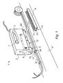
- FIG. 1 there is shown a cable gun 1 for securing clips 10 with a pin 11 over a cable X into a surface such as a skirting board Y.
- Gun 1 has a gun body 2 and a handle 3.
- An elongate magazine 4 provides a storage means to store a plurality of clips 10 with pins 11. Magazine 4 is removeable and engages with a recess 2A in body 2.
- magazine 4 When magazine 4 releasably engages with a recess 2A in the gun body, it creates a flat edge 12 to the gun body to abut against a flat surface.
- the magazine has a channel recess 13 along the flat edge to receive a cable.
- Magazine 4 acts also as a cable guide to guide cable through a driver station 5. Magazine 4 also acts as a delivery means to deliver clips 10 to a driver station 5 with a cable recess 5A which aligns with the channel 12 so that the cable is recessed into the flat edge 12.
- a driver 6 operated by trigger 7 is provided to drive the clip pin 11 at the driver station 5 as described in UK patent no 2483957 .
- the gun In use the gun is used to guide the cable X along a surface such as skirting board Y, and the trigger 7 used to secure a clip 10 over the cable as required.
- FIG. 2 there is shown a cable gun 20, according to a further embodiment/aspect (the fourth) of the invention, for securing clips 10 with a pin 11 over a cable X into a surface such as mortar Y recessed between bricks Z.
- Gun 20 has a gun body 22 and a handle 23.
- An elongate magazine 24 provides a storage means to store a plurality of clips 10 with pins 11. Magazine 24 is removeable and engages with a recess 22A in body 22.
- Gun 20 thus performs like the gun described hereinbefore (e.g. according to the second aspect of the invention) and with reference to Figure 3 .
- Magazine 24 also acts as a delivery means to deliver clips 10 to the driver station 25 with a cable recess 25B so that the cable is recessed into the recess 25B.
- a driver 26 operated by trigger 27 is provided to drive the clip pin 11 at the driver station 25 as described in UK patent no 2483957 .
- magazines each supporting clips of different types to accommodate different sizes of cable and clips.
- the clips may be standard clips which are secured to a workpiece over a cable, or the clips may be of type described in UK patent application nos. GB1121713.0 or GB1117952.0 , the disclosure of which is incorporated herein in their entirety by reference. Also it may be desirable to secure two or more cables to a surface with a single clip.
- the magazine could accommodate hooks or other devices to secure Christmas lights and the like to walls.
- any clip may be held at the driver station against a workpiece with pressure as the driver drives the pin into the workpiece, and a suitable device may be provided for this purpose.
- FIG. 3 there is shown a cable gun 1, according to another embodiment/aspect (the third) of the invention, for securing clips 10 with a pin 11 into a surface such as mortar Y recessed between bricks X.
- Gun 1 has a gun body 2 with a handle 3 to hold the gun adjacent a surface such as bricks X.
- An elongate channel 4 provides a storage means to store a plurality of clips 10 with pins 11. Clips 10 may be formed as an array of clips in a strip joined together by frangible bridging means 12. Elongate channel 4 also acts as a delivery means to deliver a clip from the storage means to a driver station 5.
- Driver station 5 includes a projection 5A to project into a recess in a workpiece such as recessed mortar Y between bricks X.
- a driver 6 is provided to drive the clip pin 11 at the driver station 5 into the surface Y to secure the cable Z to the surface Y.
- Driver 6 is a hammer with a head 6A biased by a spring 6B towards a pin 11, and head 6A can be pivoted away from pin 11 by an electrical solenoid 6C.
- Driver 6 can be operated by a trigger 7. Operation of trigger 7 causes solenoid 6 to pivot head 6A away from pin 11 so stretching spring 6B and then turns solenoid 6C "off" whereby the spring 6B drives hammer head 6A onto the pin 11 so driving the pin into the surface Y.
- Hammer head 6A includes a cutter 8 which cuts through the frangible bridging means so severing the clip at the driver station 5 from the array of clips in channel 4. Power for solenoid 6C is provided from the mains through wire 9.
- the projection 5A includes a cutout 5B to receive cable when a clip is being secured over a cable.
- the driver means may be adjustable, e.g. by altering the tension of spring 6B when stretched by the solenoid 6C, to drive a clip pin at variable forces.
- a different force could be used to drive a pin 11 depending on the nature of the surface it is being driven into (e.g. brick, wood, plastic or plaster).
- the gun may further comprise a metering means to secure a clip over the wire at predetermined intervals automatically.
- a control knob (not shown) may be provided to adjust the predetermined interval.
- the gun may be adapted to accommodate different sizes of cable and clips.
- the clips may be standard clips which are secured to a workpiece over a cable, or the clips may be of type described in UK patent application nos. GB1121713.0 or GB1117952.0 .
- any clip may be held at the driver station against a workpiece with pressure as the driver drives the pin into the workpiece, and a suitable device may be provided for this purpose.
Landscapes
- Engineering & Computer Science (AREA)
- Mechanical Engineering (AREA)
- Clamps And Clips (AREA)
Applications Claiming Priority (2)
| Application Number | Priority Date | Filing Date | Title |
|---|---|---|---|
| GB201311618A GB2515556A (en) | 2013-06-28 | 2013-06-28 | Clip gun-projection position |
| GB1311616.5A GB2515555A (en) | 2013-06-28 | 2013-06-28 | Clip gun-magazine |
Publications (2)
| Publication Number | Publication Date |
|---|---|
| EP2823936A2 true EP2823936A2 (de) | 2015-01-14 |
| EP2823936A3 EP2823936A3 (de) | 2015-04-22 |
Family
ID=51032889
Family Applications (1)
| Application Number | Title | Priority Date | Filing Date |
|---|---|---|---|
| EP20140002203 Withdrawn EP2823936A3 (de) | 2013-06-28 | 2014-06-27 | Kabelschelle mit Klammermagazin |
Country Status (1)
| Country | Link |
|---|---|
| EP (1) | EP2823936A3 (de) |
Cited By (7)
| Publication number | Priority date | Publication date | Assignee | Title |
|---|---|---|---|---|
| US12296694B2 (en) | 2021-03-10 | 2025-05-13 | Techtronic Cordless Gp | Lawnmowers |
| US12369509B2 (en) | 2022-07-19 | 2025-07-29 | Techtronic Cordless Gp | Display for controlling robotic tool |
| US12425197B2 (en) | 2022-07-29 | 2025-09-23 | Techtronic Cordless Gp | Generation of a cryptography key for a robotic garden tool |
| US12443180B2 (en) | 2021-11-10 | 2025-10-14 | Techtronic Cordless Gp | Robotic lawn mowers |
| US12472611B2 (en) | 2022-05-31 | 2025-11-18 | Techtronic Cordless Gp | Peg driver |
| US12510892B2 (en) | 2022-04-28 | 2025-12-30 | Techtronic Cordless Gp | Creation of a virtual boundary for a robotic garden tool |
| US12564130B2 (en) | 2022-01-31 | 2026-03-03 | Techtronic Cordless Gp | Robotic garden tool |
Family Cites Families (6)
| Publication number | Priority date | Publication date | Assignee | Title |
|---|---|---|---|---|
| JPS6347076A (ja) * | 1986-08-15 | 1988-02-27 | 海老原 代師行 | ステ−プラのカセツト |
| US20020108996A1 (en) * | 2001-02-15 | 2002-08-15 | Cornett Roger Dennis | Hand-held staple gun for non-metallic sheathed cable |
| US6481612B1 (en) * | 2002-04-02 | 2002-11-19 | Peter G. Mangone, Jr. | Fastening device delivery tool with perpendicular ram driven by a repeatable arcuate force member |
| US6848607B2 (en) * | 2003-02-25 | 2005-02-01 | Acme Staple Company, Inc. | Fastening tool with modified driver travel path |
| US20080156844A1 (en) * | 2007-01-03 | 2008-07-03 | Austin Raymond Savio Braganza | Staple gun |
| TWI413578B (zh) * | 2012-01-13 | 2013-11-01 | Apex Mfg Co Ltd | 釘槍 |
-
2014
- 2014-06-27 EP EP20140002203 patent/EP2823936A3/de not_active Withdrawn
Cited By (7)
| Publication number | Priority date | Publication date | Assignee | Title |
|---|---|---|---|---|
| US12296694B2 (en) | 2021-03-10 | 2025-05-13 | Techtronic Cordless Gp | Lawnmowers |
| US12443180B2 (en) | 2021-11-10 | 2025-10-14 | Techtronic Cordless Gp | Robotic lawn mowers |
| US12564130B2 (en) | 2022-01-31 | 2026-03-03 | Techtronic Cordless Gp | Robotic garden tool |
| US12510892B2 (en) | 2022-04-28 | 2025-12-30 | Techtronic Cordless Gp | Creation of a virtual boundary for a robotic garden tool |
| US12472611B2 (en) | 2022-05-31 | 2025-11-18 | Techtronic Cordless Gp | Peg driver |
| US12369509B2 (en) | 2022-07-19 | 2025-07-29 | Techtronic Cordless Gp | Display for controlling robotic tool |
| US12425197B2 (en) | 2022-07-29 | 2025-09-23 | Techtronic Cordless Gp | Generation of a cryptography key for a robotic garden tool |
Also Published As
| Publication number | Publication date |
|---|---|
| EP2823936A3 (de) | 2015-04-22 |
Similar Documents
| Publication | Publication Date | Title |
|---|---|---|
| EP2823936A2 (de) | Kabelschelle mit Klammermagazin | |
| US20140197222A1 (en) | Cable clip gun | |
| EP2734338B1 (de) | Kabelschellenpistole | |
| GB2515556A (en) | Clip gun-projection position | |
| US20040247415A1 (en) | Slotted fastener and fastening method | |
| US2670919A (en) | Adjustable support for ceiling lighting fixtures | |
| US20170157758A1 (en) | Clip dispensing means and clips and storage means therefore | |
| AU2015298805B2 (en) | Ground anchor | |
| US9085073B2 (en) | Combination staple holder and removal tool | |
| EP1943960A3 (de) | Chirurgische Klammervorrichtung mit gebogenem Schneidelement | |
| GB2515555A (en) | Clip gun-magazine | |
| US9829027B1 (en) | Collated staple strip assembly | |
| US10247329B2 (en) | Cable fastener with hook structure for supporting a cable | |
| US20200130159A1 (en) | Fastener holder and dispenser | |
| US9322493B2 (en) | Cable fastener with hook structure for supporting a cable | |
| US10978862B2 (en) | Cable bracket | |
| US9692214B2 (en) | Dispenser for cable support and method | |
| GB2500403A (en) | Strip of cable clips | |
| DE50303447D1 (de) | Vorrichtung zur Halterung von Klemmschellen in einer vorbestimmten Lage | |
| GB2492853A (en) | Cable clip gun | |
| US10023373B2 (en) | Collating strip for plug and plug installation method | |
| GB2447906A (en) | Material retainer | |
| US5267391A (en) | Tool for installing demountable-wall clips on wall-board panels | |
| US20080241294A1 (en) | Tile grouting machine | |
| US12479072B2 (en) | Screw-in aid for screwing in a long screw |
Legal Events
| Date | Code | Title | Description |
|---|---|---|---|
| 17P | Request for examination filed |
Effective date: 20140627 |
|
| AK | Designated contracting states |
Kind code of ref document: A2 Designated state(s): AL AT BE BG CH CY CZ DE DK EE ES FI FR GB GR HR HU IE IS IT LI LT LU LV MC MK MT NL NO PL PT RO RS SE SI SK SM TR |
|
| AX | Request for extension of the european patent |
Extension state: BA ME |
|
| PUAI | Public reference made under article 153(3) epc to a published international application that has entered the european phase |
Free format text: ORIGINAL CODE: 0009012 |
|
| PUAL | Search report despatched |
Free format text: ORIGINAL CODE: 0009013 |
|
| AK | Designated contracting states |
Kind code of ref document: A3 Designated state(s): AL AT BE BG CH CY CZ DE DK EE ES FI FR GB GR HR HU IE IS IT LI LT LU LV MC MK MT NL NO PL PT RO RS SE SI SK SM TR |
|
| AX | Request for extension of the european patent |
Extension state: BA ME |
|
| RIC1 | Information provided on ipc code assigned before grant |
Ipc: B25C 5/16 20060101AFI20150313BHEP |
|
| STAA | Information on the status of an ep patent application or granted ep patent |
Free format text: STATUS: THE APPLICATION IS DEEMED TO BE WITHDRAWN |
|
| 18D | Application deemed to be withdrawn |
Effective date: 20151023 |