EP2823918A1 - Guide bush adjusting device - Google Patents
Guide bush adjusting device Download PDFInfo
- Publication number
- EP2823918A1 EP2823918A1 EP13757658.3A EP13757658A EP2823918A1 EP 2823918 A1 EP2823918 A1 EP 2823918A1 EP 13757658 A EP13757658 A EP 13757658A EP 2823918 A1 EP2823918 A1 EP 2823918A1
- Authority
- EP
- European Patent Office
- Prior art keywords
- guide bush
- operation member
- pin
- hole
- connection member
- Prior art date
- Legal status (The legal status is an assumption and is not a legal conclusion. Google has not performed a legal analysis and makes no representation as to the accuracy of the status listed.)
- Granted
Links
Images




Classifications
-
- B—PERFORMING OPERATIONS; TRANSPORTING
- B23—MACHINE TOOLS; METAL-WORKING NOT OTHERWISE PROVIDED FOR
- B23B—TURNING; BORING
- B23B13/00—Arrangements for automatically conveying or chucking or guiding stock
- B23B13/12—Accessories, e.g. stops, grippers
- B23B13/123—Grippers, pushers or guiding tubes
-
- B—PERFORMING OPERATIONS; TRANSPORTING
- B23—MACHINE TOOLS; METAL-WORKING NOT OTHERWISE PROVIDED FOR
- B23B—TURNING; BORING
- B23B31/00—Chucks; Expansion mandrels; Adaptations thereof for remote control
- B23B31/02—Chucks
- B23B31/10—Chucks characterised by the retaining or gripping devices or their immediate operating means
- B23B31/12—Chucks with simultaneously-acting jaws, whether or not also individually adjustable
- B23B31/20—Longitudinally-split sleeves, e.g. collet chucks
- B23B31/201—Characterized by features relating primarily to remote control of the gripping means
- B23B31/207—Characterized by features relating primarily to remote control of the gripping means using mechanical transmission through the spindle
- B23B31/2072—Axially moving cam, fixed jaws
-
- B—PERFORMING OPERATIONS; TRANSPORTING
- B23—MACHINE TOOLS; METAL-WORKING NOT OTHERWISE PROVIDED FOR
- B23B—TURNING; BORING
- B23B13/00—Arrangements for automatically conveying or chucking or guiding stock
- B23B13/12—Accessories, e.g. stops, grippers
- B23B13/126—Supports
-
- B—PERFORMING OPERATIONS; TRANSPORTING
- B23—MACHINE TOOLS; METAL-WORKING NOT OTHERWISE PROVIDED FOR
- B23Q—DETAILS, COMPONENTS, OR ACCESSORIES FOR MACHINE TOOLS, e.g. ARRANGEMENTS FOR COPYING OR CONTROLLING; MACHINE TOOLS IN GENERAL CHARACTERISED BY THE CONSTRUCTION OF PARTICULAR DETAILS OR COMPONENTS; COMBINATIONS OR ASSOCIATIONS OF METAL-WORKING MACHINES, NOT DIRECTED TO A PARTICULAR RESULT
- B23Q1/00—Members which are comprised in the general build-up of a form of machine, particularly relatively large fixed members
- B23Q1/72—Auxiliary arrangements; Interconnections between auxiliary tables and movable machine elements
- B23Q1/76—Steadies; Rests
- B23Q1/763—Rotating steadies or rests
-
- Y—GENERAL TAGGING OF NEW TECHNOLOGICAL DEVELOPMENTS; GENERAL TAGGING OF CROSS-SECTIONAL TECHNOLOGIES SPANNING OVER SEVERAL SECTIONS OF THE IPC; TECHNICAL SUBJECTS COVERED BY FORMER USPC CROSS-REFERENCE ART COLLECTIONS [XRACs] AND DIGESTS
- Y10—TECHNICAL SUBJECTS COVERED BY FORMER USPC
- Y10T—TECHNICAL SUBJECTS COVERED BY FORMER US CLASSIFICATION
- Y10T82/00—Turning
- Y10T82/25—Lathe
- Y10T82/2593—Work rest
Definitions
- the present invention relates to a guide bush adjusting device configured to adjust an inner diameter dimension of a guide bush.
- Guide bush units for machine tools have heretofore been known in which a guide bush with a predetermined adjusted inner diameter dimension guides a bar material inserted in the guide bush.
- One of what are known as guide bush adjusting devices configured to adjust the inner diameter dimension of the guide bush includes: a guide bush sleeve configured to house the guide bush; a guide bush adjusting nut provided to be displaceable with respect to the guide bush sleeve; and a fixing device to fix the guide bush adjusting nut to the guide bush sleeve (see Patent Literature 1, for example).
- the guide bush adjusting device is configured to adjust the inner diameter dimension of the guide bush by: connecting the guide bush adjusting nut and the guide bush together; releasing the guide bush adjusting nut from its fixation, displacing the guide bush adjusting nut in a rotational direction by rotating the guide bush adjusting nut, and fixing the guide bush adjusting nut at a predetermined rotational position; and moving the guide bush with respect to the guide bush sleeve, and positioning the guide bush.
- Patent Literature 1 Japanese Utility Model Registration Application Publication No. Sho 61-99404 (Claim of Utility Model Registration, and FIGS. 1 to 4 )
- This position change (the change in the position of the tip end side of the guide bush adjusting nut) and the like cause a problem that it is difficult to adjust the inner diameter dimension of the guide bush with high precision because the position of the guide bush with respect to the guide bush sleeve is changed, and the inner diameter dimension of the guide bush is changed accordingly.
- a guide bush adjusting device of the present invention includes: a cylindrical body configured to house a guide bush; a mobile body provided to be displaceable with respect to the cylindrical body; and a fixing device to fix the mobile body to the cylindrical body.
- the guide bush adjusting device is configured to adjust an inner diameter dimension of the guide bush by connecting the mobile body and the guide bush together, releasing the mobile body from its fixation, displacing the mobile body, and fixing the mobile body at a predetermined position, and moving the guide bush with respect to the cylindrical body, and positioning the guide bush.
- the mobile body includes a connection member configured to be connected to the guide bush, and an operation member configured to operate displacement of the connection member.
- the connection member and the operation member are connected together by use of an engagement section including a recessed portion and a projecting portion to be loosely fitted (fitted loosely by means of play) to each other.
- the operation member is fixed by use of the fixing device.
- the fixing device be configured to fix the mobile body by elastically (resiliently) enlarging a diameter of the operation member, and pressing the operation member against the cylindrical body.
- the mobile body be displaced in a rotational direction with respect to the cylindrical body.
- the engagement section be formed from a pin as the projection portion, and the recessed portion into which the pin is inserted.
- the pin and the hole be loosely fitted to each other in a way as to be relatively displaceable within a predetermined range in a direction of movement of the mobile body, and that the pin include a retainer portion configured to prevent the pin from coming out of the hole, and obtained by forming a tip end of the pin, which has passed through the hole, in a size larger than that of the hole.
- the thus-configured guide bush adjusting device of the present invention prevents a change in the position of the connection member and the like by use of the engagement section, even if the position of the operation member is changed when the operation member is fixed using the fixing device.
- the change in the inner diameter dimension of the guide bush can be suppressed, in particular even when the position of the operation member is changed easily because the fixing device is configured to fix the mobile body by elastically enlarging the diameter of the operation member, and thus pressing the operation member against the cylindrical body.
- the mobile body may be of a type which adjusts the inner diameter dimension of the guide bush by being displaced in the rotational direction with respect to the cylindrical body.
- An advantage of this case is that the engagement section can be easily and simply formed from: the pin as the projecting portion; and the recessed portion in which the pin is inserted.
- the retainer portion in the pin will never allow the operation member and the connection member to become separated from each other when: the pin is loosely fitted in the hole as the recessed portion in a way that the pin and the hole are relatively displaceable in the predetermined direction in the direction of the movement of the mobile body; and the pin includes the retainer portion configured to prevent the pin from coming out of the hole, and obtained by forming the tip end of the pin penetrating through the hole into the size larger than that of the hole. For this reason, once the operation member is taken out of the cylindrical body by releasing the operation member from the fixation by the fixing device, the connection member, together with the operation member, is taken out of the cylindrical body. Accordingly, the connection member will never be left inside the cylindrical body.
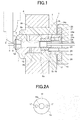
- FIG. 1 shows a cross-sectional view of a main part of a guide bush unit 1 which includes a guide bush adjusting device of the present invention.
- the guide bush unit 1 is provided on an automatic lathe which is a machine tool.
- the guide bush unit 1 guides a bar material 2, which is held by a main spindle of the automatic lathe, in a way to allow the bar material 2 to move in an axial center direction and rotate around an axial center.
- the automatic lathe is capable of machining a part of the bar material 2, which juts out from a tip end of the guide bush unit 1, with a tool 3.
- the guide bush unit 1 is attached to a guide bush support base 4 which is uprightly installed on a bed side of the automatic lathe.
- the guide bush unit 1 includes a guide bush holder 6 which is detachably attached to the guide bush support base 4.
- a cylindrical guide bush sleeve 7 is integrally inserted in and fixed to the guide bush holder 6.
- the guide bush sleeve 7 has a three-stepped through-hole 8 in its center, and the diameter of the through-hole 8 is different among the three steps.
- a guide bush 9 is inserted in a small-diameter hole portion 8a on a tip end side of the through-hole 8.
- a tapered surface 12 corresponding to a tapered surface 11 of the guide bush 9 is formed on a tip end-side circumferential surface of the through-hole 8.
- the guide bush 9 is placed inside the guide bush sleeve 7 with the tapered surfaces 11, 12 in contact with each other, and with a base end portion 9b projecting into a middle-diameter hole portion 8b which continues to the small-diameter hole portion 8a.
- a key groove 9a is formed in a part of a peripheral surface of the guide bush 9.
- a rotation stopper pin 13 is inserted in the key groove 9a in a way that the rotation stopper pin 13 projects into the smaller-diameter hole portion 8a in the bush sleeve 7.
- a hollow cylindrical screw connection member 14 provided with an internal thread to threadedly engage with an external thread formed on the base end portion 9b of the guide bush 9 is rotatably inserted in the middle-diameter hole portion 8b.
- a tip end of the screw connection member 14 is in contact with an end surface of the middle-diameter hole portion 8b.
- a flange 16 is provided to a base end potion of the screw connection member 14. The flange 16 is situated inside a large-diameter hole portion 8c which continues to the middle-diameter hole portion 8b. As shown in FIG. 2A , engagement holes 17 are formed in the flange 16.
- a hollow cylindrical operation member 18 is rotatably inserted in the large-diameter hole portion 8c.
- Pins 19 are projectingly provided to a tip end surface of the operation member 18.
- the pins 19 are provided there by being press-fitted in holes 25 drilled in the operation member 18.
- the pins 19 which are projecting portions are inserted in the engagement holes 17 which are recessed portions.
- the diameters of the engagement holes 17 are set larger than the diameters of the pins 19, respectively, to an extent that the pins 19 have predetermined play in the engagement holes 17.
- Each engagement hole 17 and the corresponding pin 19 engage with each other in a loosely fitted state of being loosely fitted to each other.
- slits 21 extending in an axial line direction are formed in the operation member 18.
- a screw hole 22 extending from a base end surface side in the axial line direction is formed between facing surfaces of each slit 21.
- a tapered surface 22a provided with no thread is formed at an end portion of each screw hole 22.
- a screw 23 is threadedly engaged with each screw hole 22.
- a tapered surface 23a is formed between a head portion and a shank of each screw 23.
- a slit 20 extending in a circumferential direction is formed continuing to an end portion of each slit 21. Threaded engagement of the screws 23 with the screw holes 22 makes the tapered surfaces 23a of the screws 23 press the tapered surfaces 22a of the screw holes 22, and thereby the base end portion of the operation member 18 elastically expands in its radial directions.
- the operation member 18 When the outer peripheral surface of the operation member 18 is pressed against the peripheral surface of the large-diameter hole portion 8c, the operation member 18 is unrotatably positioned and fixed to the guide bush sleeve 7 with friction force.
- the base end portion returns from the elastically deformed shape to the original shape, and the outer peripheral surface of the operation member 18 is released from the state of being pressed against the peripheral surface of the large-diameter 8c.
- the operation member 18 is allowed to rotate.
- the screw connection member 14 integrally rotates with the assistance of the pins 19.
- the slits 21, the screw holes 22 and the screws 23 constitute a fixing device 29 to fix the operation member 18 to the guide bush sleeve 7 by elastically enlarging the diameter of the base end portion of the operation member 18.
- the fixing device 29 is integrally provided to the operation member 18.
- the guide bush 9 moves in the axial line direction, its inner diameter dimension is adjusted in accordance with how the tapered surfaces 11, 12 are pressed against each other.
- the inner diameter dimension of the guide bush 9 can be fixed to a predetermined value.
- a drawbar 24 configured to adjust the inner diameter dimension of the guide bush 9 by moving the guide bush 9 in the axial line direction is formed from: the screw connection member 14 which is a connection member to be threadedly engaged with and connected to the guide bush 9; and the operation member 18 integrally provided with the fixing device 29.
- the screw connection member 14 and the operation member 18 are engaged with and connected to each other with the assistance of an engagement section including the engagement holes 17 and the pins 19 which are loosely fitted to one another.
- the drawbar 24 rotates with respect to the guide bush sleeve 7 as the screw connection member 14 rotates integrally in accordance with the rotational operation of the operation member 18.
- the drawbar 24 constitutes a mobile body to be displaced in the rotational direction along with its rotation with respect to the guide bush sleeve 7.
- the drawbar 24 is fixed to the guide bush sleeve 7 by the fixation using the operation member 18.
- the inner diameter dimension of the guide bush 9 is adjusted on the basis of the displacement of the drawbar 24 in the rotational direction.
- the bar material 2 passes through a center hole 18c of the operation member 18 and a center hole 14c of the screw connection member 14, and is inserted through the guide bush 9.
- a tip end portion of the bar material 2 juts out from the guide bush 9.
- the inner diameter dimension of the guide bush 9 is adjusted in order for the guide bush 9 to support the bar material 2 with a slight clearance enough to allow the bar material 2 to move in the axial line direction and to rotate around the axis line.
- the guide bush unit 1 guides the bar material 2 by use of the guide bush 9.
- the inner diameter dimension of the guide bush 9 is easily adjusted and fixed when the operation member 18 is rotated and fixed at the predetermined angle position.
- an operation handle 26 is rotatably fitted onto a base end side of the guide bush sleeve 7. As shown in FIG. 5 , a pin 28 is projectingly provided to the operation handle 26, while a hole 27 to engage with the pin 28 is formed in the operation member 18.
- the insertion of the pin 28 into the hole 27 links the operation handle 26 and the operation member 18 together.
- the operation handle 26 is rotationally operated, the operation member 18 is easily rotated through the pin 28. Accordingly, the inner diameter dimension of the guide bush 9 can be adjusted easily.
- the operation handle 26 may be detachably provided. By detaching the operation handle 26 after the adjustment of the inner diameter dimension of the guide bush 9, it is possible to enhance accessibility to the guide bush 9 by the main spindle.
- the operation member 18 may take on any shape as long as such a shape allows the fixation to the guide bush sleeve 7 by the expansion in the radial directions. In the case of the fixation of the operation member 18 to the guide bush sleeve 7, however, a variety of displacement on the tip end side of the operation member 18 is conceivable depending on the shape and the like of the operation member 18.
- FIGS. 6A and 6B it is possible to provide a C ring-shaped operation member 32, shaped like the letter C in a cross-sectional view, with a slit 31 formed in only one end side of the operation member.
- the diameter of the operation member 32 is enlarged, it is likely that the operation member 32 is displaced in a rotational direction in which the pins 19 come closer to each other toward an opposite end portion of the operation member 32 from the slit 31.
- the rotation of the screw connection member 14 can be suppressed by use of the play between engagement hole 17 and the corresponding pin 19, and the like. This makes it possible to precisely adjust and maintain the inner diameter dimension of the guide bush 9.
- the slit 31, the screw hole 22 and the screw 23 constitute the fixing device 29 for fixing the operation member 18 to the guide bush sleeve 7 by elastically enlarging the diameter of the base end portion of the operation member 18.
- the descriptions have been provided for the example in which the engagement section is formed from the pins 19 and the engagement holes 17.
- the engagement section may be formed by combining the pins 19 and grooves 33 which are recessed portions, as shown in FIG. 7A .
- the engagement section may be formed by use of a recessed-and-projecting fitting structure 34 (obtained by combining recessed and projecting parts), as shown in FIG. 7B .
- the guide bush adjusting device of the present invention may include the engagement section which, as shown in FIG. 8 , is formed from a pin 19' as a projecting portion and an engagement hole 17' as a recessed portion.
- the operation member 18 is provided with the engagement hole 17' penetrating therethrough in its axial line direction P, and the pin 19' is loosely inserted (loosely fitted) in the engagement hole 17'.
- a shank portion 19a', and a head portion 19b' (a retainer portion) thicker than the shank portion 19a' are formed in the pin 19'.
- the engagement hole 17' is a stepped hole including: a shank-portion hole 17a' into which the shank portion 19a' is loosely inserted, and which is formed in a size not allowing the head portion 19b' to pass through; and a head-portion hole 17b' into which the head portion 19b' is loosely inserted.
- the distance ⁇ L for the clearance is set longer than a distance (a distance ⁇ K in FIG. 9 which will be described later) by which the position of the tip end-side portion (the end portion closer to the screw connection member 14) of the operation member 18 changes when, as shown FIG. 4 , the operation member 18 is fixed to the guide bush sleeve 7 by: threadedly engaging the screws 23 with the screw holes 22 in the operation member 18; pressing the tapered surfaces 22a of the screw holes 22 with the tapered surfaces 23a of the screws 23; and thereby expanding the base end portion of the operation member 18 in the radial directions.
- the diameter of the outer peripheral surface of the operation member 18 is smaller than the inner diameter of the large-diameter hole portion 8c.
- the operation member 18 and the screw connection member 14 integrally move in the rotational direction. For these reasons, once the operation member 18 rotates with respect to the large-diameter hole portion 8c, the screw connection member 14 also rotates, integrally with the operation member 18, with respect to the middle-diameter hole portion 8b.
- the clearance between the step portion 17c' of the engagement hole 17' and the head portion 19b' of the pin 19' enables the operation member 18 and the screw connection member 14 to be relatively displaced in the axial line direction P within a range of the distance ⁇ L.
- the screw connection member 14 is rotatably inserted in the middle-diameter hole portion 8b of the guide bush sleeve 7 while the operation member 18 is rotatably inserted in the large-diameter hole portion 8c thereof, as in the case of the foregoing embodiment.
- the internal thread formed in the inner peripheral surface of the screw connection member 14 threadedly engages with the external thread formed on the outer peripheral surface of the base end portion 9b of the guide bush 9.
- the contact of the tip end of the screw connection member 14 with the end surface of the middle-diameter hole portion 8b restrains the screw connection member 14 from moving in the axial line direction P, while the rotation stopper pin 13 and the key groove 9a restrain the rotation of the guide bush 9.
- the rotation of the screw connection member 14 makes the guide bush 9 move in the axial line direction P.
- the operation member 18 and the screw connection member 14 are relatively displaceable in the axial line direction P within the range of the distance ⁇ L for the above-described clearance. For this reason, although the operation member 18 moves back in the axial line direction P, the distance ⁇ K of the backward movement falls within the range of the distance ⁇ L within which the operation member 18 and the screw connection member 14 are relatively displaceable ( ⁇ K ⁇ L). Accordingly, as shown in FIG. 9 , only the operation member 18 moves back, but the screw connection member 14 does not move back.
- the operation member 18 and the screw connection member 14 are released from a load of restriction in the through-hole 8 of the guide bush sleeve 7.
- the step portion 17c' in the operation member 18 hits the head portion 19b' of the pin 19'.
- the pin 19' is pulled out rearward together with the operation member 18, and the screw connection member 14 in which the pin 19' is press-fitted is also pulled out rearward.
- FIGS. 8 and 9 show the example in which: the engagement hole 17' is formed in the operation member 18; and the pin 19' is provided to the screw connection member 14. It should be noted, however, that the guide bush adjusting device of the present invention is not limited to this example.
- the guide bush adjusting device of the present invention may have a configuration reverse to the one in FIGS. 8 and 9 , in which the pin 19' is provided to the operation member 18 and the engagement hole 17' is formed in the screw connection member 14. This configuration also exerts the same working and effects as those of the example shown in FIGS. 8 and 9 .
Landscapes
- Engineering & Computer Science (AREA)
- Mechanical Engineering (AREA)
- Turning (AREA)
- Transmission Devices (AREA)
- Mutual Connection Of Rods And Tubes (AREA)
Abstract
Description
- The present invention relates to a guide bush adjusting device configured to adjust an inner diameter dimension of a guide bush.
- Guide bush units for machine tools have heretofore been known in which a guide bush with a predetermined adjusted inner diameter dimension guides a bar material inserted in the guide bush.
- One of what are known as guide bush adjusting devices configured to adjust the inner diameter dimension of the guide bush includes: a guide bush sleeve configured to house the guide bush; a guide bush adjusting nut provided to be displaceable with respect to the guide bush sleeve; and a fixing device to fix the guide bush adjusting nut to the guide bush sleeve (see
Patent Literature 1, for example). - The guide bush adjusting device is configured to adjust the inner diameter dimension of the guide bush by: connecting the guide bush adjusting nut and the guide bush together; releasing the guide bush adjusting nut from its fixation, displacing the guide bush adjusting nut in a rotational direction by rotating the guide bush adjusting nut, and fixing the guide bush adjusting nut at a predetermined rotational position; and moving the guide bush with respect to the guide bush sleeve, and positioning the guide bush.
- Patent Literature 1: Japanese Utility Model Registration Application Publication No.
Sho 61-99404 FIGS. 1 to 4 ) - However, an internal thread portion and an expandable slit portion, which constitute the guide bush adjusting nut are integrated together. For this reason, when the guide bush adjusting nut is fixed at the predetermined rotational position, the slit portion of the guide bush adjusting nut is expanded in response to the fixation. This makes it likely that: the guide bush adjusting nut is deformed partially; and the position of a tip end side of the guide bush adjusting nut accordingly changes.
- This position change (the change in the position of the tip end side of the guide bush adjusting nut) and the like cause a problem that it is difficult to adjust the inner diameter dimension of the guide bush with high precision because the position of the guide bush with respect to the guide bush sleeve is changed, and the inner diameter dimension of the guide bush is changed accordingly.
- To solve the problem, a guide bush adjusting device of the present invention includes: a cylindrical body configured to house a guide bush; a mobile body provided to be displaceable with respect to the cylindrical body; and a fixing device to fix the mobile body to the cylindrical body. The guide bush adjusting device is configured to adjust an inner diameter dimension of the guide bush by connecting the mobile body and the guide bush together, releasing the mobile body from its fixation, displacing the mobile body, and fixing the mobile body at a predetermined position, and moving the guide bush with respect to the cylindrical body, and positioning the guide bush. Here, the mobile body includes a connection member configured to be connected to the guide bush, and an operation member configured to operate displacement of the connection member. The connection member and the operation member are connected together by use of an engagement section including a recessed portion and a projecting portion to be loosely fitted (fitted loosely by means of play) to each other. The operation member is fixed by use of the fixing device.
- In the guide bush adjusting device of the present invention, it is preferable that the fixing device be configured to fix the mobile body by elastically (resiliently) enlarging a diameter of the operation member, and pressing the operation member against the cylindrical body.
- In the guide bush adjusting device of the present invention, it is preferable that the mobile body be displaced in a rotational direction with respect to the cylindrical body.
- In this case, it is preferable that the engagement section be formed from a pin as the projection portion, and the recessed portion into which the pin is inserted.
- Furthermore, when a hole is applied as the recessed portion, it is preferable that the pin and the hole be loosely fitted to each other in a way as to be relatively displaceable within a predetermined range in a direction of movement of the mobile body, and that the pin include a retainer portion configured to prevent the pin from coming out of the hole, and obtained by forming a tip end of the pin, which has passed through the hole, in a size larger than that of the hole.
- The thus-configured guide bush adjusting device of the present invention prevents a change in the position of the connection member and the like by use of the engagement section, even if the position of the operation member is changed when the operation member is fixed using the fixing device.
- Accordingly, a change in the position of the guide bush connected to the connection member is prevented, and a change in the inner diameter dimension of the guide bush is prevented. This brings about an effect that the inner diameter dimension of the guide bush can be precisely adjusted and maintained.
- The change in the inner diameter dimension of the guide bush can be suppressed, in particular even when the position of the operation member is changed easily because the fixing device is configured to fix the mobile body by elastically enlarging the diameter of the operation member, and thus pressing the operation member against the cylindrical body.
- It should be noted that the mobile body may be of a type which adjusts the inner diameter dimension of the guide bush by being displaced in the rotational direction with respect to the cylindrical body. An advantage of this case is that the engagement section can be easily and simply formed from: the pin as the projecting portion; and the recessed portion in which the pin is inserted.
- The retainer portion in the pin will never allow the operation member and the connection member to become separated from each other when: the pin is loosely fitted in the hole as the recessed portion in a way that the pin and the hole are relatively displaceable in the predetermined direction in the direction of the movement of the mobile body; and the pin includes the retainer portion configured to prevent the pin from coming out of the hole, and obtained by forming the tip end of the pin penetrating through the hole into the size larger than that of the hole. For this reason, once the operation member is taken out of the cylindrical body by releasing the operation member from the fixation by the fixing device, the connection member, together with the operation member, is taken out of the cylindrical body. Accordingly, the connection member will never be left inside the cylindrical body.
-
- [
FIG. 1] FIG. 1 is a main part front cross-sectional view of a guide bush unit (a diagram showing a cross section taken along the A-A line ofFIG. 2B ). - [
FIG. 2A] FIG. 2A is a right side view of a screw connection member. - [
FIG. 2B] FIG. 2B is a right side view of an operation member. - [
FIG. 3] FIG. 3 is a plan view showing how the diameter of the operation member is enlarged. - [
FIG. 4] FIG. 4 is a view including plan views showing how the operation member is fixed to a guide bush sleeve. - [
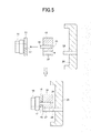
FIG. 5] FIG. 5 is a view including main part front cross-sectional views showing how the screw connection member, the operation member and an operation handle are linked together. - [
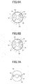
FIG. 6A] FIG. 6A is a right side view of an operation member shaped like a C-ring, and is a drawing showing how the operation member is released from its fixation. - [
FIG. 6B] FIG. 6B is a right side view of the operation member shaped like the C-ring, and is a drawing showing how the operation member is fixed. - [
FIG. 7A] FIG. 7A is a right side view of the screw connection member, showing an engagement section which uses grooves as recessed portions. - [
FIG. 7B] FIG. 7B is a main part front cross-sectional view of the screw connection member and the operation member, showing an engagement section which is formed from a recess-and-projecting fitting structure. - [
FIG. 8] FIG. 8 is a main part cross-sectional view showing an example of a guide bush adjusting device having a configuration in which: a pin having a head portion is loosely inserted in an engagement hole formed in the operation member; and an opposite end portion of the pin from the head portion is press-fitted in the screw connection member, showing how the fixation is released. - [
FIG. 9] FIG. 9 is a main part cross-sectional view showing the example of the guide bush adjusting device having the configuration in which: the pin having the head portion is loosely inserted in the engagement hole formed in the operation member; and the opposite end portion of the pin from the head portion is press-fitted in the screw connection member, showing how the fixation is achieved. -
FIG. 1 shows a cross-sectional view of a main part of aguide bush unit 1 which includes a guide bush adjusting device of the present invention. - The
guide bush unit 1 is provided on an automatic lathe which is a machine tool. Theguide bush unit 1 guides abar material 2, which is held by a main spindle of the automatic lathe, in a way to allow thebar material 2 to move in an axial center direction and rotate around an axial center. The automatic lathe is capable of machining a part of thebar material 2, which juts out from a tip end of theguide bush unit 1, with atool 3. - The
guide bush unit 1 is attached to a guidebush support base 4 which is uprightly installed on a bed side of the automatic lathe. Theguide bush unit 1 includes a guide bush holder 6 which is detachably attached to the guidebush support base 4. A cylindricalguide bush sleeve 7 is integrally inserted in and fixed to the guide bush holder 6. - The
guide bush sleeve 7 has a three-stepped through-hole 8 in its center, and the diameter of the through-hole 8 is different among the three steps. Aguide bush 9 is inserted in a small-diameter hole portion 8a on a tip end side of the through-hole 8. A taperedsurface 12 corresponding to a taperedsurface 11 of theguide bush 9 is formed on a tip end-side circumferential surface of the through-hole 8. - The
guide bush 9 is placed inside theguide bush sleeve 7 with the tapered surfaces 11, 12 in contact with each other, and with abase end portion 9b projecting into a middle-diameter hole portion 8b which continues to the small-diameter hole portion 8a. - A
key groove 9a is formed in a part of a peripheral surface of theguide bush 9. Arotation stopper pin 13 is inserted in thekey groove 9a in a way that therotation stopper pin 13 projects into the smaller-diameter hole portion 8a in thebush sleeve 7. Once theguide bush 9 is inserted and installed in theguide bush sleeve 7, therotation stopper pin 13 and thekey groove 9a restrain the rotation of theguide bush 9 in theguide bush sleeve 7. - A hollow cylindrical
screw connection member 14 provided with an internal thread to threadedly engage with an external thread formed on thebase end portion 9b of theguide bush 9 is rotatably inserted in the middle-diameter hole portion 8b. - A tip end of the
screw connection member 14 is in contact with an end surface of the middle-diameter hole portion 8b. Aflange 16 is provided to a base end potion of thescrew connection member 14. Theflange 16 is situated inside a large-diameter hole portion 8c which continues to the middle-diameter hole portion 8b. As shown inFIG. 2A , engagement holes 17 are formed in theflange 16. - A hollow
cylindrical operation member 18 is rotatably inserted in the large-diameter hole portion 8c.Pins 19 are projectingly provided to a tip end surface of theoperation member 18. Thepins 19 are provided there by being press-fitted inholes 25 drilled in theoperation member 18. Thepins 19 which are projecting portions are inserted in the engagement holes 17 which are recessed portions. The diameters of the engagement holes 17 are set larger than the diameters of thepins 19, respectively, to an extent that thepins 19 have predetermined play in the engagement holes 17. Eachengagement hole 17 and thecorresponding pin 19 engage with each other in a loosely fitted state of being loosely fitted to each other. - As shown in
FIG. 2B , slits 21 extending in an axial line direction are formed in theoperation member 18. Ascrew hole 22 extending from a base end surface side in the axial line direction is formed between facing surfaces of each slit 21. Atapered surface 22a provided with no thread is formed at an end portion of eachscrew hole 22. Ascrew 23 is threadedly engaged with eachscrew hole 22. - As shown in
FIG. 3 , atapered surface 23a is formed between a head portion and a shank of eachscrew 23. In theoperation member 18, aslit 20 extending in a circumferential direction is formed continuing to an end portion of each slit 21. Threaded engagement of thescrews 23 with the screw holes 22 makes thetapered surfaces 23a of thescrews 23 press the taperedsurfaces 22a of the screw holes 22, and thereby the base end portion of theoperation member 18 elastically expands in its radial directions. - As shown in
FIG. 4 , when theoperation member 18 expands in its radial directions inside the through-hole 8, its outer peripheral surface is pressed against the peripheral surface of the large-diameter hole portion 8c. - When the outer peripheral surface of the
operation member 18 is pressed against the peripheral surface of the large-diameter hole portion 8c, theoperation member 18 is unrotatably positioned and fixed to theguide bush sleeve 7 with friction force. - When the
screws 23 are pulled out of the screw holes 22, the base end portion returns from the elastically deformed shape to the original shape, and the outer peripheral surface of theoperation member 18 is released from the state of being pressed against the peripheral surface of the large-diameter 8c. Thus, theoperation member 18 is allowed to rotate. - By releasing the fixation of the
operation member 18 to theguide bush sleeve 7 and then rotating theoperation member 18, thescrew connection member 14 integrally rotates with the assistance of thepins 19. Theslits 21, the screw holes 22 and thescrews 23 constitute a fixing device 29 to fix theoperation member 18 to theguide bush sleeve 7 by elastically enlarging the diameter of the base end portion of theoperation member 18. The fixing device 29 is integrally provided to theoperation member 18. - Since the tip end of the
screw connection member 14 is in contact with the end surface of the middle-diameter hole portion 8b and therotation stopper pin 13 and thekey groove 9a restrain the rotation of theguide bush 9, the rotation of thescrew connection member 14 makes theguide bush 9 move in the axial line direction. - As the
guide bush 9 moves in the axial line direction, its inner diameter dimension is adjusted in accordance with how the tapered surfaces 11, 12 are pressed against each other. When theoperation member 18 is positioned and fixed to theguide bush sleeve 7 at a predetermined rotational angle position, the inner diameter dimension of theguide bush 9 can be fixed to a predetermined value. - A
drawbar 24 configured to adjust the inner diameter dimension of theguide bush 9 by moving theguide bush 9 in the axial line direction is formed from: thescrew connection member 14 which is a connection member to be threadedly engaged with and connected to theguide bush 9; and theoperation member 18 integrally provided with the fixing device 29. - The
screw connection member 14 and theoperation member 18 are engaged with and connected to each other with the assistance of an engagement section including the engagement holes 17 and thepins 19 which are loosely fitted to one another. - The
drawbar 24 rotates with respect to theguide bush sleeve 7 as thescrew connection member 14 rotates integrally in accordance with the rotational operation of theoperation member 18. Thedrawbar 24 constitutes a mobile body to be displaced in the rotational direction along with its rotation with respect to theguide bush sleeve 7. - The
drawbar 24 is fixed to theguide bush sleeve 7 by the fixation using theoperation member 18. The inner diameter dimension of theguide bush 9 is adjusted on the basis of the displacement of thedrawbar 24 in the rotational direction. - The
bar material 2 passes through acenter hole 18c of theoperation member 18 and acenter hole 14c of thescrew connection member 14, and is inserted through theguide bush 9. A tip end portion of thebar material 2 juts out from theguide bush 9. The inner diameter dimension of theguide bush 9 is adjusted in order for theguide bush 9 to support thebar material 2 with a slight clearance enough to allow thebar material 2 to move in the axial line direction and to rotate around the axis line. - The
guide bush unit 1 guides thebar material 2 by use of theguide bush 9. The inner diameter dimension of theguide bush 9 is easily adjusted and fixed when theoperation member 18 is rotated and fixed at the predetermined angle position. - In the embodiment, an
operation handle 26 is rotatably fitted onto a base end side of theguide bush sleeve 7. As shown inFIG. 5 , apin 28 is projectingly provided to theoperation handle 26, while ahole 27 to engage with thepin 28 is formed in theoperation member 18. - The insertion of the
pin 28 into thehole 27 links the operation handle 26 and theoperation member 18 together. When the operation handle 26 is rotationally operated, theoperation member 18 is easily rotated through thepin 28. Accordingly, the inner diameter dimension of theguide bush 9 can be adjusted easily. - The operation handle 26 may be detachably provided. By detaching the operation handle 26 after the adjustment of the inner diameter dimension of the
guide bush 9, it is possible to enhance accessibility to theguide bush 9 by the main spindle. - When the
operation member 18 is fixed to the side of theguide bush sleeve 7, the position of its tip end side is changed as a result of the expansion of the base end portion in the radial directions. - For example, as shown in
FIG. 4 , when theoperation member 18 is fixed to theguide bush sleeve 7, its tip end side is likely to move slightly toward the base end side as a result of the expansion of the base end portion in the radial directions. At this time, by the movement of thepins 19 into the respective engagement holes 17, and the like, thescrew connection member 14 is prevented from moving in accordance with the displacement of the tip end side of theoperation member 18. - For this reason, when the
drawbar 24 is fixed to theguide bush sleeve 7 by fixing theoperation member 18 with the fixing device 29, it is possible to avoid inconvenience of moving theguide bush 9 in such a direction to draw theguide bush 9 into theguide bush sleeve 7, and thus to precisely adjust and maintain the inner diameter dimension of theguide bush 9. - It should be noted that the
operation member 18 may take on any shape as long as such a shape allows the fixation to theguide bush sleeve 7 by the expansion in the radial directions. In the case of the fixation of theoperation member 18 to theguide bush sleeve 7, however, a variety of displacement on the tip end side of theoperation member 18 is conceivable depending on the shape and the like of theoperation member 18. - For example, as shown in
FIGS. 6A and 6B , it is possible to provide a C ring-shapedoperation member 32, shaped like the letter C in a cross-sectional view, with aslit 31 formed in only one end side of the operation member. In this case, when the diameter of theoperation member 32 is enlarged, it is likely that theoperation member 32 is displaced in a rotational direction in which thepins 19 come closer to each other toward an opposite end portion of theoperation member 32 from theslit 31. However, the rotation of thescrew connection member 14 can be suppressed by use of the play betweenengagement hole 17 and thecorresponding pin 19, and the like. This makes it possible to precisely adjust and maintain the inner diameter dimension of theguide bush 9. - In this case, the
slit 31, thescrew hole 22 and thescrew 23 constitute the fixing device 29 for fixing theoperation member 18 to theguide bush sleeve 7 by elastically enlarging the diameter of the base end portion of theoperation member 18. - In the above embodiment, the descriptions have been provided for the example in which the engagement section is formed from the
pins 19 and the engagement holes 17. Instead, however, the engagement section may be formed by combining thepins 19 andgrooves 33 which are recessed portions, as shown inFIG. 7A . Otherwise, the engagement section may be formed by use of a recessed-and-projecting fitting structure 34 (obtained by combining recessed and projecting parts), as shown inFIG. 7B . - Furthermore, the guide bush adjusting device of the present invention may include the engagement section which, as shown in
FIG. 8 , is formed from a pin 19' as a projecting portion and an engagement hole 17' as a recessed portion. - Specifically, the
operation member 18 is provided with the engagement hole 17' penetrating therethrough in its axial line direction P, and the pin 19' is loosely inserted (loosely fitted) in the engagement hole 17'. - A
shank portion 19a', and ahead portion 19b' (a retainer portion) thicker than theshank portion 19a' are formed in the pin 19'. The engagement hole 17' is a stepped hole including: a shank-portion hole 17a' into which theshank portion 19a' is loosely inserted, and which is formed in a size not allowing thehead portion 19b' to pass through; and a head-portion hole 17b' into which thehead portion 19b' is loosely inserted. - With the pin 19' penetrating through the engagement hole 17', an end portion of the pin 19', which is opposite from an end portion at which the
head portion 19b' is formed, is press-fitted in thescrew connection member 14. - As a result, the
head portion 19b' of the pin 19' is prevented from coming off the engagement hole 17', as well as theoperation member 18 and thescrew connection member 14 are kept connected to each other. - With the pin 19' penetrating through the engagement hole 17' and press-fitted in the
screw connection member 14, and with thescrew connection member 14 and theoperation member 18 in contact with each other, a clearance with a distance ΔL is formed between thehead portion 19b' of the pin 19' and astep portion 17c' of the engagement portion 17' (a boundary portion between the shank-potion hole 17a' and the head-portion hole 17b') and thehead portion 19b' of the pin 19', as shown inFIG. 8 . - The distance ΔL for the clearance is set longer than a distance (a distance ΔK in
FIG. 9 which will be described later) by which the position of the tip end-side portion (the end portion closer to the screw connection member 14) of theoperation member 18 changes when, as shownFIG. 4 , theoperation member 18 is fixed to theguide bush sleeve 7 by: threadedly engaging thescrews 23 with the screw holes 22 in theoperation member 18; pressing thetapered surfaces 22a of the screw holes 22 with thetapered surfaces 23a of thescrews 23; and thereby expanding the base end portion of theoperation member 18 in the radial directions. - The diameter of the outer peripheral surface of the
operation member 18 is smaller than the inner diameter of the large-diameter hole portion 8c. In addition, with the engagement hole 17' and the pin 19' in engagement with each other, theoperation member 18 and thescrew connection member 14 integrally move in the rotational direction. For these reasons, once theoperation member 18 rotates with respect to the large-diameter hole portion 8c, thescrew connection member 14 also rotates, integrally with theoperation member 18, with respect to the middle-diameter hole portion 8b. - Meanwhile, the clearance between the
step portion 17c' of the engagement hole 17' and thehead portion 19b' of the pin 19' enables theoperation member 18 and thescrew connection member 14 to be relatively displaced in the axial line direction P within a range of the distance ΔL. - In the embodiment in which the
operation member 18 and thescrew connection member 14 are formed in this manner, thescrew connection member 14 is rotatably inserted in the middle-diameter hole portion 8b of theguide bush sleeve 7 while theoperation member 18 is rotatably inserted in the large-diameter hole portion 8c thereof, as in the case of the foregoing embodiment. - When the
operation member 18 is rotated by the operation handle 26 and the like, thescrew connection member 14 integrally rotates with the assistance of the pin 19' and the engagement hole 17'. When theoperation member 18 rotates, the end surface of theoperation member 18 comes into contact with the end surface of thescrew connection member 14. - As the
screw connection member 14 rotates, the internal thread formed in the inner peripheral surface of thescrew connection member 14 threadedly engages with the external thread formed on the outer peripheral surface of thebase end portion 9b of theguide bush 9. However, the contact of the tip end of thescrew connection member 14 with the end surface of the middle-diameter hole portion 8b restrains thescrew connection member 14 from moving in the axial line direction P, while therotation stopper pin 13 and thekey groove 9a restrain the rotation of theguide bush 9. For these reasons, the rotation of thescrew connection member 14 makes theguide bush 9 move in the axial line direction P. - As the
guide bush 9 moves in the axial line direction P, its inner diameter dimension is adjusted in accordance with how the tapered surfaces 11, 12 are pressed against each other. - With the inner diameter dimension of the
guide bush 9 adjusted, once theoperation member 18 is fixed to theguide bush sleeve 7, as in the case shown inFIG. 3 , by threadedly engaging thescrews 23 with the screw holes 22 and thereby elastically enlarging the diameter of the base end portion of theoperation member 18, the engagement of the pin 19' and the engagement hole 17' restrains the rotation of thescrew connection member 14 as well, and the inner diameter dimension of theguide bush 9 is fixed. - When the diameter of the base end portion of the
operation member 18 is elastically enlarged, the end portion of theoperation member 18, which is closer to thescrew connection member 14, moves back away from the screw connection member 14 (has positional displacement) by a slight distance ΔK, as shown inFIG. 9 . - The
operation member 18 and thescrew connection member 14 are relatively displaceable in the axial line direction P within the range of the distance ΔL for the above-described clearance. For this reason, although theoperation member 18 moves back in the axial line direction P, the distance ΔK of the backward movement falls within the range of the distance ΔL within which theoperation member 18 and thescrew connection member 14 are relatively displaceable (ΔK<ΔL). Accordingly, as shown inFIG. 9 , only theoperation member 18 moves back, but thescrew connection member 14 does not move back. - In addition, although the clearance with the distance ΔK occurs between the
operation member 18 and thescrew connection member 14 in the axial line direction P, the rotation of thescrew connection member 14 is restrained by the engagement between the pin 19' and the engagement hole 17'. For this reason, theguide bush 9 will never be displaced in the axial line direction P by the rotation of thescrew connection member 14. - As described above, when the
drawbar 24 is fixed to theguide bush sleeve 7 by fixing theoperation member 18 by use of the fixing device 29, it is possible to avoid the inconvenience of moving theguide bush 9 in the direction to draw theguide bush 9 into theguide bush sleeve 7, and thus to precisely adjust and maintain the inner diameter dimension of theguide bush 9. - When the base end portion of the
operation member 18 is returned to the state before the deformation by loosening thescrews 23, the fixation of theoperation member 18 to theguide bush sleeve 7 is released, and theoperation member 18 is rotated with the operation handle 26 and the like, thescrew connection member 14 also rotates because of the engagement between the engagement hole 17' and the pin 19', and is detached from thebase end portion 9b of theguide bush 9. - Thereby, the
operation member 18 and thescrew connection member 14 are released from a load of restriction in the through-hole 8 of theguide bush sleeve 7. When theoperation member 18 is pulled out rearward (in a direction away from the guide bush 9), thestep portion 17c' in theoperation member 18 hits thehead portion 19b' of the pin 19'. Thus, the pin 19' is pulled out rearward together with theoperation member 18, and thescrew connection member 14 in which the pin 19' is press-fitted is also pulled out rearward. - Accordingly, it is possible to prevent a situation in which only the
operation member 18 is pulled out while thescrew connection member 14 is left in the through-hole 8. -
FIGS. 8 and9 show the example in which: the engagement hole 17' is formed in theoperation member 18; and the pin 19' is provided to thescrew connection member 14. It should be noted, however, that the guide bush adjusting device of the present invention is not limited to this example. The guide bush adjusting device of the present invention may have a configuration reverse to the one inFIGS. 8 and9 , in which the pin 19' is provided to theoperation member 18 and the engagement hole 17' is formed in thescrew connection member 14. This configuration also exerts the same working and effects as those of the example shown inFIGS. 8 and9 . - This application claims the benefit of priority based on Japanese Patent Application No.
2012-051555 -
- 1
- guide bush unit
- 7
- guide bush sleeve (cylindrical body)
- 9
- guide bush
- 14
- screw connection member (connection member)
- 17
- engagement hole (recessed portion)
- 18
- operation member
- 19
- pin (projecting portion)
- 24
- drawbar (mobile body)
- 29
- fixing device
Claims (5)
- A guide bush adjusting device, comprising:a cylindrical body configured to house a guide bush;a mobile body provided to be displaceable with respect to the cylindrical body; anda fixing device to fix the mobile body to the cylindrical body,the guide bush adjusting device being configured to adjust an inner diameter dimension of the guide bush by
connecting the mobile body and the guide bush together, releasing the mobile body from its fixation, displacing the mobile body, and fixing the mobile body at a predetermined position, and
moving the guide bush with respect to the cylindrical body, and positioning the guide bush, whereinthe mobile body includes
a connection member configured to be connected to the guide bush, and
an operation member configured to operate displacement of the connection member,the connection member and the operation member are connected together by use of an engagement section including a recessed portion and a projecting portion to be loosely fitted to each other, andthe operation member is fixed by use of the fixing device. - The guide bush adjusting device of claim 1, wherein the fixing device is configured to fix the mobile body by elastically enlarging a diameter of the operation member and pressing the operation member against the cylindrical body.
- The guide bush adjusting device of claim 1 or 2, wherein the mobile body is displaced in a rotational direction with respect to the cylindrical body.
- The guide bush adjusting device of claim 3, wherein the engagement section is formed from a pin as the projection portion, and the recessed portion into which the pin is inserted.
- The guide bush adjusting device of claim 4, wherein
the recessed portion is a hole,
the pin and the hole are loosely fitted to each other in a way as to be relatively displaceable within a predetermined range in a direction of movement of the mobile body, and
the pin includes a retainer portion configured to prevent the pin from coming out of the hole, and obtained by forming a tip end of the pin, which has passed through the hole, in a size larger than a size of the hole.
Applications Claiming Priority (2)
| Application Number | Priority Date | Filing Date | Title |
|---|---|---|---|
| JP2012051555 | 2012-03-08 | ||
| PCT/JP2013/053320 WO2013132974A1 (en) | 2012-03-08 | 2013-02-13 | Guide bush adjusting device |
Publications (3)
| Publication Number | Publication Date |
|---|---|
| EP2823918A1 true EP2823918A1 (en) | 2015-01-14 |
| EP2823918A4 EP2823918A4 (en) | 2015-11-04 |
| EP2823918B1 EP2823918B1 (en) | 2020-11-04 |
Family
ID=49116458
Family Applications (1)
| Application Number | Title | Priority Date | Filing Date |
|---|---|---|---|
| EP13757658.3A Active EP2823918B1 (en) | 2012-03-08 | 2013-02-13 | Guide bush adjusting device |
Country Status (8)
| Country | Link |
|---|---|
| US (1) | US9616500B2 (en) |
| EP (1) | EP2823918B1 (en) |
| JP (1) | JP6005725B2 (en) |
| KR (1) | KR101692598B1 (en) |
| CN (1) | CN104144761B (en) |
| ES (1) | ES2830025T3 (en) |
| TW (1) | TWI566860B (en) |
| WO (1) | WO2013132974A1 (en) |
Families Citing this family (3)
| Publication number | Priority date | Publication date | Assignee | Title |
|---|---|---|---|---|
| US9592556B2 (en) * | 2012-03-30 | 2017-03-14 | Citizen Machinery Co., Ltd. | Processing machine |
| CN110586966A (en) * | 2019-07-31 | 2019-12-20 | 广州市昊志机电股份有限公司 | Pull rod structure and main shaft |
| US11833630B2 (en) | 2021-05-28 | 2023-12-05 | Yamazaki Mazak Corporation | Machine tool with removable workpiece support |
Family Cites Families (18)
| Publication number | Priority date | Publication date | Assignee | Title |
|---|---|---|---|---|
| JPS5316153B2 (en) * | 1971-12-13 | 1978-05-30 | ||
| US4258598A (en) | 1979-06-11 | 1981-03-31 | Alkron Manufacturing Corp. | Rotating guide bushing for Swiss-type automatic screw machine |
| JPS6199404A (en) | 1984-10-19 | 1986-05-17 | Dx Antenna Co Ltd | Amplitude limiter |
| JPH035361Y2 (en) | 1984-12-07 | 1991-02-12 | ||
| US4971339A (en) * | 1988-06-17 | 1990-11-20 | Illinois Tool Works, Inc. | Collet type work driver |
| EP0388214A1 (en) | 1989-03-17 | 1990-09-19 | The Dow Chemical Company | Ceramic greenware formulation for dry pressed greenware |
| JP2992569B2 (en) * | 1990-10-25 | 1999-12-20 | 株式会社ツガミ | Lathe guide bush device |
| JPH0865583A (en) * | 1994-08-19 | 1996-03-08 | Fujitsu General Ltd | Display device |
| JP3785544B2 (en) * | 1996-02-01 | 2006-06-14 | 株式会社ニイガタマシンテクノ | Machine tool spindle equipment |
| JP3759261B2 (en) | 1996-11-11 | 2006-03-22 | シチズン時計株式会社 | NC automatic lathe guide bush adjusting method and adjusting device |
| US6036409A (en) * | 1997-01-23 | 2000-03-14 | The Boeing Company | Blind hole self-collet countersink |
| JP4201553B2 (en) * | 2002-08-30 | 2008-12-24 | シチズンホールディングス株式会社 | Material guide device and automatic lathe |
| US6883407B2 (en) * | 2002-08-30 | 2005-04-26 | Hardinge Inc. | Expanding collet assembly for pick-off spindle |
| US7303363B2 (en) | 2003-09-10 | 2007-12-04 | Lockheed Martin Corporation | Pneumatic drill |
| EP1731248A4 (en) | 2004-03-31 | 2010-06-16 | Citizen Holdings Co Ltd | Material guide device and automatic lathe |
| SG116631A1 (en) * | 2004-05-04 | 2005-11-28 | Erowa Ag | Clamping apparatus for fixing a collet to a chuck. |
| CN201168791Y (en) * | 2008-04-09 | 2008-12-24 | 杭州轴瓦有限公司 | Bush high speed fine boring cutter relieving main shaft |
| CN201579629U (en) * | 2009-12-19 | 2010-09-15 | 朱俊生 | Clamp for drilling spiral distribution holes on bush |
-
2013
- 2013-02-13 JP JP2014503733A patent/JP6005725B2/en active Active
- 2013-02-13 EP EP13757658.3A patent/EP2823918B1/en active Active
- 2013-02-13 WO PCT/JP2013/053320 patent/WO2013132974A1/en not_active Ceased
- 2013-02-13 CN CN201380012382.3A patent/CN104144761B/en active Active
- 2013-02-13 US US14/382,635 patent/US9616500B2/en active Active
- 2013-02-13 KR KR1020147024489A patent/KR101692598B1/en active Active
- 2013-02-13 ES ES13757658T patent/ES2830025T3/en active Active
- 2013-02-26 TW TW102106732A patent/TWI566860B/en active
Also Published As
| Publication number | Publication date |
|---|---|
| KR101692598B1 (en) | 2017-01-03 |
| WO2013132974A1 (en) | 2013-09-12 |
| US20150047480A1 (en) | 2015-02-19 |
| JPWO2013132974A1 (en) | 2015-07-30 |
| TWI566860B (en) | 2017-01-21 |
| TW201400211A (en) | 2014-01-01 |
| CN104144761A (en) | 2014-11-12 |
| ES2830025T3 (en) | 2021-06-02 |
| US9616500B2 (en) | 2017-04-11 |
| CN104144761B (en) | 2016-08-24 |
| EP2823918A4 (en) | 2015-11-04 |
| EP2823918B1 (en) | 2020-11-04 |
| JP6005725B2 (en) | 2016-10-12 |
| KR20140125832A (en) | 2014-10-29 |
Similar Documents
| Publication | Publication Date | Title |
|---|---|---|
| US9616500B2 (en) | Guide bush adjusting device | |
| JP3198457U (en) | Flare tool | |
| JP6732219B2 (en) | Base holder and power tool | |
| JP2016209960A (en) | Nut runner system | |
| JP4705977B2 (en) | Chuck device | |
| EP3127638A1 (en) | Tool mounting portion, tool holder for machine tool provided with said tool mounting portion, and machine tool | |
| KR101628015B1 (en) | The boring bar | |
| KR101666363B1 (en) | back lash adjusting device for screw and boring bar using it | |
| KR101578330B1 (en) | The boring bar | |
| WO2014132849A1 (en) | Punch die | |
| JP4246525B2 (en) | Fastening device | |
| JPWO2007138890A1 (en) | Shank attachment structure | |
| JP2001121374A (en) | Tool holder holding device | |
| EP3263252B1 (en) | Operating device and rotating device | |
| EP1731248A1 (en) | Material guide device and automatic lathe | |
| JP3141314U (en) | Drill with centering function | |
| JP7401921B2 (en) | coupling device | |
| JP2002219605A (en) | Holder and chuck device | |
| JP2012152862A (en) | Anti-vibration device | |
| JP6711527B2 (en) | Guide bush device | |
| JP2006043854A (en) | Tap holder | |
| JP3181779U (en) | Flare tool | |
| JP2007301664A (en) | Multi-pawl chuck | |
| JP2001087912A (en) | Collet chuck and chuck device | |
| CN220145770U (en) | Shaft part positioning device |
Legal Events
| Date | Code | Title | Description |
|---|---|---|---|
| PUAI | Public reference made under article 153(3) epc to a published international application that has entered the european phase |
Free format text: ORIGINAL CODE: 0009012 |
|
| 17P | Request for examination filed |
Effective date: 20140902 |
|
| AK | Designated contracting states |
Kind code of ref document: A1 Designated state(s): AL AT BE BG CH CY CZ DE DK EE ES FI FR GB GR HR HU IE IS IT LI LT LU LV MC MK MT NL NO PL PT RO RS SE SI SK SM TR |
|
| AX | Request for extension of the european patent |
Extension state: BA ME |
|
| DAX | Request for extension of the european patent (deleted) | ||
| RAP1 | Party data changed (applicant data changed or rights of an application transferred) |
Owner name: CITIZEN MACHINERY CO., LTD. Owner name: CITIZEN HOLDINGS CO., LTD. |
|
| RA4 | Supplementary search report drawn up and despatched (corrected) |
Effective date: 20151005 |
|
| RIC1 | Information provided on ipc code assigned before grant |
Ipc: B23B 13/12 20060101AFI20150929BHEP |
|
| RAP1 | Party data changed (applicant data changed or rights of an application transferred) |
Owner name: CITIZEN MACHINERY CO., LTD. Owner name: CITIZEN WATCH CO., LTD. |
|
| STAA | Information on the status of an ep patent application or granted ep patent |
Free format text: STATUS: EXAMINATION IS IN PROGRESS |
|
| 17Q | First examination report despatched |
Effective date: 20181115 |
|
| GRAP | Despatch of communication of intention to grant a patent |
Free format text: ORIGINAL CODE: EPIDOSNIGR1 |
|
| STAA | Information on the status of an ep patent application or granted ep patent |
Free format text: STATUS: GRANT OF PATENT IS INTENDED |
|
| INTG | Intention to grant announced |
Effective date: 20200401 |
|
| GRAJ | Information related to disapproval of communication of intention to grant by the applicant or resumption of examination proceedings by the epo deleted |
Free format text: ORIGINAL CODE: EPIDOSDIGR1 |
|
| STAA | Information on the status of an ep patent application or granted ep patent |
Free format text: STATUS: EXAMINATION IS IN PROGRESS |
|
| INTC | Intention to grant announced (deleted) | ||
| GRAP | Despatch of communication of intention to grant a patent |
Free format text: ORIGINAL CODE: EPIDOSNIGR1 |
|
| STAA | Information on the status of an ep patent application or granted ep patent |
Free format text: STATUS: GRANT OF PATENT IS INTENDED |
|
| INTG | Intention to grant announced |
Effective date: 20200624 |
|
| GRAS | Grant fee paid |
Free format text: ORIGINAL CODE: EPIDOSNIGR3 |
|
| GRAA | (expected) grant |
Free format text: ORIGINAL CODE: 0009210 |
|
| STAA | Information on the status of an ep patent application or granted ep patent |
Free format text: STATUS: THE PATENT HAS BEEN GRANTED |
|
| AK | Designated contracting states |
Kind code of ref document: B1 Designated state(s): AL AT BE BG CH CY CZ DE DK EE ES FI FR GB GR HR HU IE IS IT LI LT LU LV MC MK MT NL NO PL PT RO RS SE SI SK SM TR |
|
| REG | Reference to a national code |
Ref country code: GB Ref legal event code: FG4D |
|
| REG | Reference to a national code |
Ref country code: CH Ref legal event code: NV Representative=s name: BRAUNPAT BRAUN EDER AG, CH Ref country code: CH Ref legal event code: EP |
|
| REG | Reference to a national code |
Ref country code: AT Ref legal event code: REF Ref document number: 1330152 Country of ref document: AT Kind code of ref document: T Effective date: 20201115 |
|
| REG | Reference to a national code |
Ref country code: IE Ref legal event code: FG4D |
|
| REG | Reference to a national code |
Ref country code: DE Ref legal event code: R096 Ref document number: 602013073792 Country of ref document: DE |
|
| REG | Reference to a national code |
Ref country code: NL Ref legal event code: MP Effective date: 20201104 |
|
| REG | Reference to a national code |
Ref country code: AT Ref legal event code: MK05 Ref document number: 1330152 Country of ref document: AT Kind code of ref document: T Effective date: 20201104 |
|
| PG25 | Lapsed in a contracting state [announced via postgrant information from national office to epo] |
Ref country code: PT Free format text: LAPSE BECAUSE OF FAILURE TO SUBMIT A TRANSLATION OF THE DESCRIPTION OR TO PAY THE FEE WITHIN THE PRESCRIBED TIME-LIMIT Effective date: 20210304 Ref country code: NO Free format text: LAPSE BECAUSE OF FAILURE TO SUBMIT A TRANSLATION OF THE DESCRIPTION OR TO PAY THE FEE WITHIN THE PRESCRIBED TIME-LIMIT Effective date: 20210204 Ref country code: RS Free format text: LAPSE BECAUSE OF FAILURE TO SUBMIT A TRANSLATION OF THE DESCRIPTION OR TO PAY THE FEE WITHIN THE PRESCRIBED TIME-LIMIT Effective date: 20201104 Ref country code: FI Free format text: LAPSE BECAUSE OF FAILURE TO SUBMIT A TRANSLATION OF THE DESCRIPTION OR TO PAY THE FEE WITHIN THE PRESCRIBED TIME-LIMIT Effective date: 20201104 Ref country code: GR Free format text: LAPSE BECAUSE OF FAILURE TO SUBMIT A TRANSLATION OF THE DESCRIPTION OR TO PAY THE FEE WITHIN THE PRESCRIBED TIME-LIMIT Effective date: 20210205 |
|
| PG25 | Lapsed in a contracting state [announced via postgrant information from national office to epo] |
Ref country code: AT Free format text: LAPSE BECAUSE OF FAILURE TO SUBMIT A TRANSLATION OF THE DESCRIPTION OR TO PAY THE FEE WITHIN THE PRESCRIBED TIME-LIMIT Effective date: 20201104 Ref country code: BG Free format text: LAPSE BECAUSE OF FAILURE TO SUBMIT A TRANSLATION OF THE DESCRIPTION OR TO PAY THE FEE WITHIN THE PRESCRIBED TIME-LIMIT Effective date: 20210204 Ref country code: SE Free format text: LAPSE BECAUSE OF FAILURE TO SUBMIT A TRANSLATION OF THE DESCRIPTION OR TO PAY THE FEE WITHIN THE PRESCRIBED TIME-LIMIT Effective date: 20201104 Ref country code: PL Free format text: LAPSE BECAUSE OF FAILURE TO SUBMIT A TRANSLATION OF THE DESCRIPTION OR TO PAY THE FEE WITHIN THE PRESCRIBED TIME-LIMIT Effective date: 20201104 Ref country code: LV Free format text: LAPSE BECAUSE OF FAILURE TO SUBMIT A TRANSLATION OF THE DESCRIPTION OR TO PAY THE FEE WITHIN THE PRESCRIBED TIME-LIMIT Effective date: 20201104 Ref country code: IS Free format text: LAPSE BECAUSE OF FAILURE TO SUBMIT A TRANSLATION OF THE DESCRIPTION OR TO PAY THE FEE WITHIN THE PRESCRIBED TIME-LIMIT Effective date: 20210304 |
|
| REG | Reference to a national code |
Ref country code: ES Ref legal event code: FG2A Ref document number: 2830025 Country of ref document: ES Kind code of ref document: T3 Effective date: 20210602 |
|
| REG | Reference to a national code |
Ref country code: LT Ref legal event code: MG9D |
|
| PG25 | Lapsed in a contracting state [announced via postgrant information from national office to epo] |
Ref country code: HR Free format text: LAPSE BECAUSE OF FAILURE TO SUBMIT A TRANSLATION OF THE DESCRIPTION OR TO PAY THE FEE WITHIN THE PRESCRIBED TIME-LIMIT Effective date: 20201104 |
|
| PG25 | Lapsed in a contracting state [announced via postgrant information from national office to epo] |
Ref country code: RO Free format text: LAPSE BECAUSE OF FAILURE TO SUBMIT A TRANSLATION OF THE DESCRIPTION OR TO PAY THE FEE WITHIN THE PRESCRIBED TIME-LIMIT Effective date: 20201104 Ref country code: SK Free format text: LAPSE BECAUSE OF FAILURE TO SUBMIT A TRANSLATION OF THE DESCRIPTION OR TO PAY THE FEE WITHIN THE PRESCRIBED TIME-LIMIT Effective date: 20201104 Ref country code: LT Free format text: LAPSE BECAUSE OF FAILURE TO SUBMIT A TRANSLATION OF THE DESCRIPTION OR TO PAY THE FEE WITHIN THE PRESCRIBED TIME-LIMIT Effective date: 20201104 Ref country code: SM Free format text: LAPSE BECAUSE OF FAILURE TO SUBMIT A TRANSLATION OF THE DESCRIPTION OR TO PAY THE FEE WITHIN THE PRESCRIBED TIME-LIMIT Effective date: 20201104 Ref country code: CZ Free format text: LAPSE BECAUSE OF FAILURE TO SUBMIT A TRANSLATION OF THE DESCRIPTION OR TO PAY THE FEE WITHIN THE PRESCRIBED TIME-LIMIT Effective date: 20201104 Ref country code: EE Free format text: LAPSE BECAUSE OF FAILURE TO SUBMIT A TRANSLATION OF THE DESCRIPTION OR TO PAY THE FEE WITHIN THE PRESCRIBED TIME-LIMIT Effective date: 20201104 |
|
| REG | Reference to a national code |
Ref country code: DE Ref legal event code: R097 Ref document number: 602013073792 Country of ref document: DE |
|
| PG25 | Lapsed in a contracting state [announced via postgrant information from national office to epo] |
Ref country code: DK Free format text: LAPSE BECAUSE OF FAILURE TO SUBMIT A TRANSLATION OF THE DESCRIPTION OR TO PAY THE FEE WITHIN THE PRESCRIBED TIME-LIMIT Effective date: 20201104 |
|
| PLBE | No opposition filed within time limit |
Free format text: ORIGINAL CODE: 0009261 |
|
| STAA | Information on the status of an ep patent application or granted ep patent |
Free format text: STATUS: NO OPPOSITION FILED WITHIN TIME LIMIT |
|
| PG25 | Lapsed in a contracting state [announced via postgrant information from national office to epo] |
Ref country code: MC Free format text: LAPSE BECAUSE OF FAILURE TO SUBMIT A TRANSLATION OF THE DESCRIPTION OR TO PAY THE FEE WITHIN THE PRESCRIBED TIME-LIMIT Effective date: 20201104 |
|
| 26N | No opposition filed |
Effective date: 20210805 |
|
| GBPC | Gb: european patent ceased through non-payment of renewal fee |
Effective date: 20210213 |
|
| REG | Reference to a national code |
Ref country code: BE Ref legal event code: MM Effective date: 20210228 |
|
| PG25 | Lapsed in a contracting state [announced via postgrant information from national office to epo] |
Ref country code: NL Free format text: LAPSE BECAUSE OF FAILURE TO SUBMIT A TRANSLATION OF THE DESCRIPTION OR TO PAY THE FEE WITHIN THE PRESCRIBED TIME-LIMIT Effective date: 20201104 Ref country code: LU Free format text: LAPSE BECAUSE OF NON-PAYMENT OF DUE FEES Effective date: 20210213 Ref country code: AL Free format text: LAPSE BECAUSE OF FAILURE TO SUBMIT A TRANSLATION OF THE DESCRIPTION OR TO PAY THE FEE WITHIN THE PRESCRIBED TIME-LIMIT Effective date: 20201104 |
|
| PG25 | Lapsed in a contracting state [announced via postgrant information from national office to epo] |
Ref country code: SI Free format text: LAPSE BECAUSE OF FAILURE TO SUBMIT A TRANSLATION OF THE DESCRIPTION OR TO PAY THE FEE WITHIN THE PRESCRIBED TIME-LIMIT Effective date: 20201104 |
|
| PG25 | Lapsed in a contracting state [announced via postgrant information from national office to epo] |
Ref country code: IE Free format text: LAPSE BECAUSE OF NON-PAYMENT OF DUE FEES Effective date: 20210213 Ref country code: FR Free format text: LAPSE BECAUSE OF NON-PAYMENT OF DUE FEES Effective date: 20210228 Ref country code: GB Free format text: LAPSE BECAUSE OF NON-PAYMENT OF DUE FEES Effective date: 20210213 |
|
| PG25 | Lapsed in a contracting state [announced via postgrant information from national office to epo] |
Ref country code: IS Free format text: LAPSE BECAUSE OF FAILURE TO SUBMIT A TRANSLATION OF THE DESCRIPTION OR TO PAY THE FEE WITHIN THE PRESCRIBED TIME-LIMIT Effective date: 20210304 |
|
| PG25 | Lapsed in a contracting state [announced via postgrant information from national office to epo] |
Ref country code: BE Free format text: LAPSE BECAUSE OF NON-PAYMENT OF DUE FEES Effective date: 20210228 |
|
| PG25 | Lapsed in a contracting state [announced via postgrant information from national office to epo] |
Ref country code: HU Free format text: LAPSE BECAUSE OF FAILURE TO SUBMIT A TRANSLATION OF THE DESCRIPTION OR TO PAY THE FEE WITHIN THE PRESCRIBED TIME-LIMIT; INVALID AB INITIO Effective date: 20130213 |
|
| PG25 | Lapsed in a contracting state [announced via postgrant information from national office to epo] |
Ref country code: CY Free format text: LAPSE BECAUSE OF FAILURE TO SUBMIT A TRANSLATION OF THE DESCRIPTION OR TO PAY THE FEE WITHIN THE PRESCRIBED TIME-LIMIT Effective date: 20201104 |
|
| PG25 | Lapsed in a contracting state [announced via postgrant information from national office to epo] |
Ref country code: MK Free format text: LAPSE BECAUSE OF FAILURE TO SUBMIT A TRANSLATION OF THE DESCRIPTION OR TO PAY THE FEE WITHIN THE PRESCRIBED TIME-LIMIT Effective date: 20201104 |
|
| PG25 | Lapsed in a contracting state [announced via postgrant information from national office to epo] |
Ref country code: TR Free format text: LAPSE BECAUSE OF FAILURE TO SUBMIT A TRANSLATION OF THE DESCRIPTION OR TO PAY THE FEE WITHIN THE PRESCRIBED TIME-LIMIT Effective date: 20201104 |
|
| PG25 | Lapsed in a contracting state [announced via postgrant information from national office to epo] |
Ref country code: MT Free format text: LAPSE BECAUSE OF FAILURE TO SUBMIT A TRANSLATION OF THE DESCRIPTION OR TO PAY THE FEE WITHIN THE PRESCRIBED TIME-LIMIT Effective date: 20201104 |
|
| REG | Reference to a national code |
Ref country code: CH Ref legal event code: U11 Free format text: ST27 STATUS EVENT CODE: U-0-0-U10-U11 (AS PROVIDED BY THE NATIONAL OFFICE) Effective date: 20260301 |
|
| PGFP | Annual fee paid to national office [announced via postgrant information from national office to epo] |
Ref country code: ES Payment date: 20260304 Year of fee payment: 14 |
|
| PGFP | Annual fee paid to national office [announced via postgrant information from national office to epo] |
Ref country code: DE Payment date: 20251230 Year of fee payment: 14 |
|
| PGFP | Annual fee paid to national office [announced via postgrant information from national office to epo] |
Ref country code: IT Payment date: 20260122 Year of fee payment: 14 |
|
| PGFP | Annual fee paid to national office [announced via postgrant information from national office to epo] |
Ref country code: CH Payment date: 20260301 Year of fee payment: 14 |