EP2823848A2 - Systems and methods for percutaneous occlusion crossing - Google Patents
Systems and methods for percutaneous occlusion crossing Download PDFInfo
- Publication number
- EP2823848A2 EP2823848A2 EP20140181675 EP14181675A EP2823848A2 EP 2823848 A2 EP2823848 A2 EP 2823848A2 EP 20140181675 EP20140181675 EP 20140181675 EP 14181675 A EP14181675 A EP 14181675A EP 2823848 A2 EP2823848 A2 EP 2823848A2
- Authority
- EP
- European Patent Office
- Prior art keywords
- elongate member
- catheter
- ramp
- distal end
- clause
- Prior art date
- Legal status (The legal status is an assumption and is not a legal conclusion. Google has not performed a legal analysis and makes no representation as to the accuracy of the status listed.)
- Granted
Links
- 238000000034 method Methods 0.000 title abstract description 66
- 238000006073 displacement reaction Methods 0.000 claims description 11
- 229910001000 nickel titanium Inorganic materials 0.000 claims description 9
- HLXZNVUGXRDIFK-UHFFFAOYSA-N nickel titanium Chemical compound [Ti].[Ti].[Ti].[Ti].[Ti].[Ti].[Ti].[Ti].[Ti].[Ti].[Ti].[Ni].[Ni].[Ni].[Ni].[Ni].[Ni].[Ni].[Ni].[Ni].[Ni].[Ni].[Ni].[Ni].[Ni] HLXZNVUGXRDIFK-UHFFFAOYSA-N 0.000 claims description 9
- 230000004044 response Effects 0.000 claims description 9
- 239000012781 shape memory material Substances 0.000 claims description 9
- 239000000835 fiber Substances 0.000 claims description 8
- 239000000463 material Substances 0.000 description 11
- 206010061660 Artery dissection Diseases 0.000 description 9
- 229910001285 shape-memory alloy Inorganic materials 0.000 description 7
- 230000000149 penetrating effect Effects 0.000 description 6
- 210000001519 tissue Anatomy 0.000 description 6
- 229920000295 expanded polytetrafluoroethylene Polymers 0.000 description 5
- 238000002399 angioplasty Methods 0.000 description 4
- 230000033001 locomotion Effects 0.000 description 4
- 238000001531 micro-dissection Methods 0.000 description 4
- 230000002792 vascular Effects 0.000 description 4
- 206010003226 Arteriovenous fistula Diseases 0.000 description 3
- 208000014882 Carotid artery disease Diseases 0.000 description 3
- 206010020772 Hypertension Diseases 0.000 description 3
- 208000018262 Peripheral vascular disease Diseases 0.000 description 3
- 206010053648 Vascular occlusion Diseases 0.000 description 3
- 230000001684 chronic effect Effects 0.000 description 3
- 208000029078 coronary artery disease Diseases 0.000 description 3
- 210000004351 coronary vessel Anatomy 0.000 description 3
- 208000007232 portal hypertension Diseases 0.000 description 3
- 238000012800 visualization Methods 0.000 description 3
- 201000001320 Atherosclerosis Diseases 0.000 description 2
- 208000001778 Coronary Occlusion Diseases 0.000 description 2
- KDLHZDBZIXYQEI-UHFFFAOYSA-N Palladium Chemical compound [Pd] KDLHZDBZIXYQEI-UHFFFAOYSA-N 0.000 description 2
- 238000001574 biopsy Methods 0.000 description 2
- 210000004204 blood vessel Anatomy 0.000 description 2
- 239000002131 composite material Substances 0.000 description 2
- 238000010276 construction Methods 0.000 description 2
- 238000007887 coronary angioplasty Methods 0.000 description 2
- 238000013461 design Methods 0.000 description 2
- 239000012530 fluid Substances 0.000 description 2
- 230000006870 function Effects 0.000 description 2
- 238000011065 in-situ storage Methods 0.000 description 2
- 238000013152 interventional procedure Methods 0.000 description 2
- 229910052751 metal Inorganic materials 0.000 description 2
- 239000002184 metal Substances 0.000 description 2
- 150000002739 metals Chemical class 0.000 description 2
- 239000000203 mixture Substances 0.000 description 2
- 238000012986 modification Methods 0.000 description 2
- 230000004048 modification Effects 0.000 description 2
- BASFCYQUMIYNBI-UHFFFAOYSA-N platinum Chemical compound [Pt] BASFCYQUMIYNBI-UHFFFAOYSA-N 0.000 description 2
- 238000002604 ultrasonography Methods 0.000 description 2
- OYPRJOBELJOOCE-UHFFFAOYSA-N Calcium Chemical compound [Ca] OYPRJOBELJOOCE-UHFFFAOYSA-N 0.000 description 1
- 229920000049 Carbon (fiber) Polymers 0.000 description 1
- 208000024172 Cardiovascular disease Diseases 0.000 description 1
- 206010016717 Fistula Diseases 0.000 description 1
- HTTJABKRGRZYRN-UHFFFAOYSA-N Heparin Chemical compound OC1C(NC(=O)C)C(O)OC(COS(O)(=O)=O)C1OC1C(OS(O)(=O)=O)C(O)C(OC2C(C(OS(O)(=O)=O)C(OC3C(C(O)C(O)C(O3)C(O)=O)OS(O)(=O)=O)C(CO)O2)NS(O)(=O)=O)C(C(O)=O)O1 HTTJABKRGRZYRN-UHFFFAOYSA-N 0.000 description 1
- 229920000914 Metallic fiber Polymers 0.000 description 1
- 239000004677 Nylon Substances 0.000 description 1
- 239000004698 Polyethylene Substances 0.000 description 1
- 208000012287 Prolapse Diseases 0.000 description 1
- FAPWRFPIFSIZLT-UHFFFAOYSA-M Sodium chloride Chemical compound [Na+].[Cl-] FAPWRFPIFSIZLT-UHFFFAOYSA-M 0.000 description 1
- 229910000639 Spring steel Inorganic materials 0.000 description 1
- 208000007536 Thrombosis Diseases 0.000 description 1
- 229910045601 alloy Inorganic materials 0.000 description 1
- 239000000956 alloy Substances 0.000 description 1
- 210000003484 anatomy Anatomy 0.000 description 1
- 238000002583 angiography Methods 0.000 description 1
- 238000013459 approach Methods 0.000 description 1
- 210000001367 artery Anatomy 0.000 description 1
- 230000008901 benefit Effects 0.000 description 1
- 239000000560 biocompatible material Substances 0.000 description 1
- 230000000903 blocking effect Effects 0.000 description 1
- 230000017531 blood circulation Effects 0.000 description 1
- 229910052791 calcium Inorganic materials 0.000 description 1
- 239000011575 calcium Substances 0.000 description 1
- 210000001736 capillary Anatomy 0.000 description 1
- 239000004917 carbon fiber Substances 0.000 description 1
- 230000008859 change Effects 0.000 description 1
- 238000000576 coating method Methods 0.000 description 1
- 210000002808 connective tissue Anatomy 0.000 description 1
- 239000002872 contrast media Substances 0.000 description 1
- 230000008878 coupling Effects 0.000 description 1
- 238000010168 coupling process Methods 0.000 description 1
- 238000005859 coupling reaction Methods 0.000 description 1
- 238000002224 dissection Methods 0.000 description 1
- 230000009977 dual effect Effects 0.000 description 1
- 238000005516 engineering process Methods 0.000 description 1
- 230000003176 fibrotic effect Effects 0.000 description 1
- 230000003890 fistula Effects 0.000 description 1
- PCHJSUWPFVWCPO-UHFFFAOYSA-N gold Chemical compound [Au] PCHJSUWPFVWCPO-UHFFFAOYSA-N 0.000 description 1
- 229910052737 gold Inorganic materials 0.000 description 1
- 239000010931 gold Substances 0.000 description 1
- 238000010438 heat treatment Methods 0.000 description 1
- 229960002897 heparin Drugs 0.000 description 1
- 229920000669 heparin Polymers 0.000 description 1
- 230000002209 hydrophobic effect Effects 0.000 description 1
- 238000003384 imaging method Methods 0.000 description 1
- 210000004969 inflammatory cell Anatomy 0.000 description 1
- 239000004816 latex Substances 0.000 description 1
- 229920000126 latex Polymers 0.000 description 1
- 239000003550 marker Substances 0.000 description 1
- VNWKTOKETHGBQD-UHFFFAOYSA-N methane Chemical compound C VNWKTOKETHGBQD-UHFFFAOYSA-N 0.000 description 1
- 208000010125 myocardial infarction Diseases 0.000 description 1
- 229920001778 nylon Polymers 0.000 description 1
- 239000013307 optical fiber Substances 0.000 description 1
- 229910052763 palladium Inorganic materials 0.000 description 1
- 239000002245 particle Substances 0.000 description 1
- 230000002093 peripheral effect Effects 0.000 description 1
- 239000004033 plastic Substances 0.000 description 1
- 229920003023 plastic Polymers 0.000 description 1
- 229910052697 platinum Inorganic materials 0.000 description 1
- ZONODCCBXBRQEZ-UHFFFAOYSA-N platinum tungsten Chemical compound [W].[Pt] ZONODCCBXBRQEZ-UHFFFAOYSA-N 0.000 description 1
- HWLDNSXPUQTBOD-UHFFFAOYSA-N platinum-iridium alloy Chemical compound [Ir].[Pt] HWLDNSXPUQTBOD-UHFFFAOYSA-N 0.000 description 1
- -1 polyethylene Polymers 0.000 description 1
- 229920000573 polyethylene Polymers 0.000 description 1
- 229920001296 polysiloxane Polymers 0.000 description 1
- 229920001343 polytetrafluoroethylene Polymers 0.000 description 1
- 239000004810 polytetrafluoroethylene Substances 0.000 description 1
- 229920002635 polyurethane Polymers 0.000 description 1
- 239000004814 polyurethane Substances 0.000 description 1
- 229920000915 polyvinyl chloride Polymers 0.000 description 1
- 239000004800 polyvinyl chloride Substances 0.000 description 1
- 238000002601 radiography Methods 0.000 description 1
- 229910052703 rhodium Inorganic materials 0.000 description 1
- 239000010948 rhodium Substances 0.000 description 1
- MHOVAHRLVXNVSD-UHFFFAOYSA-N rhodium atom Chemical compound [Rh] MHOVAHRLVXNVSD-UHFFFAOYSA-N 0.000 description 1
- 239000011780 sodium chloride Substances 0.000 description 1
- 239000010935 stainless steel Substances 0.000 description 1
- 229910001220 stainless steel Inorganic materials 0.000 description 1
- 238000001356 surgical procedure Methods 0.000 description 1
- 229910052715 tantalum Inorganic materials 0.000 description 1
- GUVRBAGPIYLISA-UHFFFAOYSA-N tantalum atom Chemical compound [Ta] GUVRBAGPIYLISA-UHFFFAOYSA-N 0.000 description 1
- 238000007669 thermal treatment Methods 0.000 description 1
- 230000002537 thrombolytic effect Effects 0.000 description 1
- 210000003462 vein Anatomy 0.000 description 1
Images


Classifications
-
- A—HUMAN NECESSITIES
- A61—MEDICAL OR VETERINARY SCIENCE; HYGIENE
- A61B—DIAGNOSIS; SURGERY; IDENTIFICATION
- A61B17/00—Surgical instruments, devices or methods, e.g. tourniquets
- A61B17/32—Surgical cutting instruments
- A61B17/3205—Excision instruments
- A61B17/3207—Atherectomy devices working by cutting or abrading; Similar devices specially adapted for non-vascular obstructions
-
- A—HUMAN NECESSITIES
- A61—MEDICAL OR VETERINARY SCIENCE; HYGIENE
- A61B—DIAGNOSIS; SURGERY; IDENTIFICATION
- A61B17/00—Surgical instruments, devices or methods, e.g. tourniquets
- A61B17/22—Implements for squeezing-off ulcers or the like on the inside of inner organs of the body; Implements for scraping-out cavities of body organs, e.g. bones; Calculus removers; Calculus smashing apparatus; Apparatus for removing obstructions in blood vessels, not otherwise provided for
-
- A—HUMAN NECESSITIES
- A61—MEDICAL OR VETERINARY SCIENCE; HYGIENE
- A61M—DEVICES FOR INTRODUCING MEDIA INTO, OR ONTO, THE BODY; DEVICES FOR TRANSDUCING BODY MEDIA OR FOR TAKING MEDIA FROM THE BODY; DEVICES FOR PRODUCING OR ENDING SLEEP OR STUPOR
- A61M25/00—Catheters; Hollow probes
- A61M25/0043—Catheters; Hollow probes characterised by structural features
- A61M25/0054—Catheters; Hollow probes characterised by structural features with regions for increasing flexibility
-
- A—HUMAN NECESSITIES
- A61—MEDICAL OR VETERINARY SCIENCE; HYGIENE
- A61M—DEVICES FOR INTRODUCING MEDIA INTO, OR ONTO, THE BODY; DEVICES FOR TRANSDUCING BODY MEDIA OR FOR TAKING MEDIA FROM THE BODY; DEVICES FOR PRODUCING OR ENDING SLEEP OR STUPOR
- A61M25/00—Catheters; Hollow probes
- A61M25/0067—Catheters; Hollow probes characterised by the distal end, e.g. tips
- A61M25/0082—Catheter tip comprising a tool
-
- A—HUMAN NECESSITIES
- A61—MEDICAL OR VETERINARY SCIENCE; HYGIENE
- A61M—DEVICES FOR INTRODUCING MEDIA INTO, OR ONTO, THE BODY; DEVICES FOR TRANSDUCING BODY MEDIA OR FOR TAKING MEDIA FROM THE BODY; DEVICES FOR PRODUCING OR ENDING SLEEP OR STUPOR
- A61M25/00—Catheters; Hollow probes
- A61M25/01—Introducing, guiding, advancing, emplacing or holding catheters
- A61M25/0194—Tunnelling catheters
-
- A—HUMAN NECESSITIES
- A61—MEDICAL OR VETERINARY SCIENCE; HYGIENE
- A61B—DIAGNOSIS; SURGERY; IDENTIFICATION
- A61B17/00—Surgical instruments, devices or methods, e.g. tourniquets
- A61B17/00234—Surgical instruments, devices or methods, e.g. tourniquets for minimally invasive surgery
- A61B2017/00292—Surgical instruments, devices or methods, e.g. tourniquets for minimally invasive surgery mounted on or guided by flexible, e.g. catheter-like, means
- A61B2017/003—Steerable
- A61B2017/00305—Constructional details of the flexible means
- A61B2017/00309—Cut-outs or slits
-
- A—HUMAN NECESSITIES
- A61—MEDICAL OR VETERINARY SCIENCE; HYGIENE
- A61B—DIAGNOSIS; SURGERY; IDENTIFICATION
- A61B17/00—Surgical instruments, devices or methods, e.g. tourniquets
- A61B2017/00831—Material properties
- A61B2017/00867—Material properties shape memory effect
-
- A—HUMAN NECESSITIES
- A61—MEDICAL OR VETERINARY SCIENCE; HYGIENE
- A61B—DIAGNOSIS; SURGERY; IDENTIFICATION
- A61B17/00—Surgical instruments, devices or methods, e.g. tourniquets
- A61B17/22—Implements for squeezing-off ulcers or the like on the inside of inner organs of the body; Implements for scraping-out cavities of body organs, e.g. bones; Calculus removers; Calculus smashing apparatus; Apparatus for removing obstructions in blood vessels, not otherwise provided for
- A61B2017/22038—Implements for squeezing-off ulcers or the like on the inside of inner organs of the body; Implements for scraping-out cavities of body organs, e.g. bones; Calculus removers; Calculus smashing apparatus; Apparatus for removing obstructions in blood vessels, not otherwise provided for with a guide wire
- A61B2017/22042—Details of the tip of the guide wire
- A61B2017/22044—Details of the tip of the guide wire with a pointed tip
-
- A—HUMAN NECESSITIES
- A61—MEDICAL OR VETERINARY SCIENCE; HYGIENE
- A61B—DIAGNOSIS; SURGERY; IDENTIFICATION
- A61B17/00—Surgical instruments, devices or methods, e.g. tourniquets
- A61B17/22—Implements for squeezing-off ulcers or the like on the inside of inner organs of the body; Implements for scraping-out cavities of body organs, e.g. bones; Calculus removers; Calculus smashing apparatus; Apparatus for removing obstructions in blood vessels, not otherwise provided for
- A61B2017/22072—Implements for squeezing-off ulcers or the like on the inside of inner organs of the body; Implements for scraping-out cavities of body organs, e.g. bones; Calculus removers; Calculus smashing apparatus; Apparatus for removing obstructions in blood vessels, not otherwise provided for with an instrument channel, e.g. for replacing one instrument by the other
- A61B2017/22074—Implements for squeezing-off ulcers or the like on the inside of inner organs of the body; Implements for scraping-out cavities of body organs, e.g. bones; Calculus removers; Calculus smashing apparatus; Apparatus for removing obstructions in blood vessels, not otherwise provided for with an instrument channel, e.g. for replacing one instrument by the other the instrument being only slidable in a channel, e.g. advancing optical fibre through a channel
- A61B2017/22077—Implements for squeezing-off ulcers or the like on the inside of inner organs of the body; Implements for scraping-out cavities of body organs, e.g. bones; Calculus removers; Calculus smashing apparatus; Apparatus for removing obstructions in blood vessels, not otherwise provided for with an instrument channel, e.g. for replacing one instrument by the other the instrument being only slidable in a channel, e.g. advancing optical fibre through a channel with a part piercing the tissue
-
- A—HUMAN NECESSITIES
- A61—MEDICAL OR VETERINARY SCIENCE; HYGIENE
- A61B—DIAGNOSIS; SURGERY; IDENTIFICATION
- A61B17/00—Surgical instruments, devices or methods, e.g. tourniquets
- A61B17/22—Implements for squeezing-off ulcers or the like on the inside of inner organs of the body; Implements for scraping-out cavities of body organs, e.g. bones; Calculus removers; Calculus smashing apparatus; Apparatus for removing obstructions in blood vessels, not otherwise provided for
- A61B2017/22094—Implements for squeezing-off ulcers or the like on the inside of inner organs of the body; Implements for scraping-out cavities of body organs, e.g. bones; Calculus removers; Calculus smashing apparatus; Apparatus for removing obstructions in blood vessels, not otherwise provided for for crossing total occlusions, i.e. piercing
- A61B2017/22095—Implements for squeezing-off ulcers or the like on the inside of inner organs of the body; Implements for scraping-out cavities of body organs, e.g. bones; Calculus removers; Calculus smashing apparatus; Apparatus for removing obstructions in blood vessels, not otherwise provided for for crossing total occlusions, i.e. piercing accessing a blood vessel true lumen from the sub-intimal space
-
- A—HUMAN NECESSITIES
- A61—MEDICAL OR VETERINARY SCIENCE; HYGIENE
- A61M—DEVICES FOR INTRODUCING MEDIA INTO, OR ONTO, THE BODY; DEVICES FOR TRANSDUCING BODY MEDIA OR FOR TAKING MEDIA FROM THE BODY; DEVICES FOR PRODUCING OR ENDING SLEEP OR STUPOR
- A61M25/00—Catheters; Hollow probes
- A61M25/01—Introducing, guiding, advancing, emplacing or holding catheters
- A61M2025/018—Catheters having a lateral opening for guiding elongated means lateral to the catheter
-
- A—HUMAN NECESSITIES
- A61—MEDICAL OR VETERINARY SCIENCE; HYGIENE
- A61M—DEVICES FOR INTRODUCING MEDIA INTO, OR ONTO, THE BODY; DEVICES FOR TRANSDUCING BODY MEDIA OR FOR TAKING MEDIA FROM THE BODY; DEVICES FOR PRODUCING OR ENDING SLEEP OR STUPOR
- A61M25/00—Catheters; Hollow probes
- A61M25/01—Introducing, guiding, advancing, emplacing or holding catheters
- A61M25/0194—Tunnelling catheters
- A61M2025/0197—Tunnelling catheters for creating an artificial passage within the body, e.g. in order to go around occlusions
Definitions
- the present invention generally relates to the field of endoluminal products, and more particularly, to the field of percutaneous occlusion crossing systems and methods.
- Cardiovascular disease including atherosclerosis, is a leading cause of death in the United States.
- One method for treating atherosclerosis and other forms of vessel lumen narrowing is angioplasty.
- the objective of angioplasty is to restore adequate blood flow through the affected vessel, which may be accomplished by introducing a treatment catheter within the narrowed lumen of the vessel to dilate it.
- CTO chronic total occlusion
- the tissue composition of a CTO is generally a variable mix of collagenrich plaque, layered thrombus, calcium, and inflammatory cells with fibro-calcific caps at both ends.
- This fibrous cap may present a surface that is difficult to penetrate with a conventional medical guidewire such that one method of crossing a CTO includes utilizing a stiffer guidewire to create a new channel through the occlusion. Due to the fibrous cap of the CTO, a stiffer guidewire still may not be able to cross it and the distal end of the guidewire may buckle or prolapse within the vessel when force is applied. In addition, a clinician must take care to avoid perforation of the vessel wall when using a stiffer guidewire.
- CTOs are often defined as coronary occlusions that have had thrombolysis in myocardial infarction (TIMI) grade flow of 0 or 1 for an estimated duration of at least one month.
- Available interventional procedures to treat coronary occlusions include coronary angioplasty, e.g., percutaneous transluminal coronary angioplasty (PTCA), and stent placement, e.g., drug-eluting stent placement. These procedures are considered percutaneous because they are performed through a tube or catheter inserted into a blood vessel, rather than through an incision in the chest.
- PTCA percutaneous transluminal coronary angioplasty
- stent placement e.g., drug-eluting stent placement.
- CTOs have historically been some of the most challenging types of blockages to treat with percutaneous interventional procedures because the fibrotic and calcified nature of the CTOs makes passage difficult.
- CABG coronary artery bypass graft
- the present invention comprises systems and methods for penetrating and bypassing chronic total or near total occlusions of vessels through the use of elongate members and specialized catheters, for example, piercing catheters, reentry catheters, and multi-lumen, reentry catheters.
- the systems and methods described herein may be useful in connection with the treatment of coronary artery disease, peripheral vascular diseases, portal hypertension, carotid artery disease, renal vascular hypertension, subintimal angioplasty, biopsies, in situ fenestration of other tissues, amongst other conditions affecting anatomical conduits.
- the present invention may also be useful to pierce grafts or stent-grafts to create fenestrations and to create anatomical passages such as an arterio-venous fistula.
- a piercing catheter having a distal tip is configured to pierce and thereby cross an occlusion.
- the piercing catheter is configured to perform micro-dissection to cross the occlusion.
- Another embodiment of the present invention comprises a reentry catheter having a side-port and ramp to guide reentry of an inner elongate member from the sub-intimal space following sub-intimal dissection.
- the ramp upon withdrawing the inner elongate member to the proximal side of the side-port and ramp, the ramp is actuated to direct the inner elongate member through the side-port for reentry into the vessel from the sub-intimal space upon subsequently advancement of the inner elongate member.
- Yet another embodiment of the present invention comprises a multi-lumen reentry catheter having a side-port and ramp to guide reentry of an inner elongate member from the sub-intimal space following sub-intimal dissection.
- the reentry catheter lumens are separated by a tearable sheath which supports the ramp in a partially actuated configuration.
- the ramp is fully actuated by advancing the inner elongate member sufficient to tear the tearable sheath and thereby remove the support for the ramp, whereupon the inner elongate member can be withdrawn to allow full actuation and then advanced through the side-port for reentry into the vessel's true lumen from the sub-intimal space.
- a single device has the capabilities to perform a piercing procedure and a reentry procedure, by incorporating a piercing catheter and a reentry catheter into a single device.
- the present invention comprises systems and methods for penetrating and bypassing chronic total or near total occlusions of vessels through the use of elongate members and specialized catheters, for example, piercing catheters, reentry catheters, and multi-lumen, reentry catheters.
- the systems and methods described herein may be useful in connection with the treatment of coronary artery disease, peripheral vascular diseases, portal hypertension, carotid artery disease, renal vascular hypertension, amongst other conditions affecting anatomical conduits.
- the present invention may also be useful to pierce grafts or stent-grafts to create fenestrations and to create anatomical passages such as an arterio-venous fistula.
- a "vessel” may be an artery, vein, capillary or the like, or any other anatomical passageway or conduit existing in a healthy subject.
- an "occlusion” may be a total (e.g., a CTO), near total or partial blockage of a vessel.
- FIG. 1 is a cross-sectional view of an exemplary vessel 100 having an occlusion 105 and having multiple layers 101, 102, and 103, which may correspond to the intima, media, and adventitia layers respectively.
- an "elongate member” is a flexible element having proximal and distal ends and capable of passing through a tortuous vessel, such as a guidewire, catheter, optical fiber, or the like.
- An exemplary elongate member may comprise a blunt, rounded, or tapered distal tip, to name a few, and may be characterized by varying degrees of stiffness and/or softness, which may further vary along the length of the elongate member.
- An exemplary elongate member, or any portion thereof, can be hydrophilic or hydrophobic.
- an exemplary elongate member can be comprised of any number of materials including silicone, latex, polyurethane, polyvinyl chloride, polyethylene, nylon, PTFE, ePTFE, stainless steel, nitinol, or any other biocompatible material, including combinations of the foregoing.
- Said elongate member can be a guidewire, a catheter, or fiber.
- said elongate member is a guidewire.
- said guidewire can be placed into hollow member 333 ( FIG. 3 ) via "over the wire” or by "rapid exchange".
- FIG. 2 illustrates an elongate member 220 approaching an occlusion 205 in a vessel 200.
- a piercing system 310 (also 510 and 710 in FIGs. 5 and 7 respectively) comprises an elongate member 320 slidably housed within and supported by a piercing catheter 330.
- Piercing system 310 may be structurally and/or materially configured to cross an occlusion 305 within a vessel 300 by applying a continuous or intermittent longitudinal force or rotational (torquing) movement at the proximal end of at least one of elongate member 320 and piercing catheter 330.
- piercing catheter 330 is configured to pierce and penetrate occlusion 305.
- piercing catheter 330 has a shape and/or stiffness sufficient to pierce and penetrate occlusion 305 (or alternatively, through vessel walls), while in other embodiments, piercing catheter 330 is configured to microdissect occlusion 305.
- FIG. 7 illustrates an exemplary embodiment of a piercing catheter microdissecting an occlusion.
- piercing catheter 330 may comprise a hollow chisel 331 having a tip 332 and being coupled to the distal end of a hollow member 333.
- hollow means a passage or space therein which can allow the passage of another object.
- a plurality of hollow chisel 331, tip 332 and hollow member 333 may be comprised of the same material (e.g., cut from a single tube or formed in a common mold).
- any of hollow chisel 331, tip 332 and hollow member 333 and/or the piercing catheter 330 may be coated with an ePTFE film.
- elongate member 320 is slidably housed within and supported by hollow member 333.
- elongate member 320 is axially movable along the longitudinal axis of hollow member 333 and hollow chisel 331 such that tip 332 is laterally displaced by axial displacement of elongate member 320, for instance, axial displacement on the order of 1 mm.
- tip 332 may be laterally displaced (e.g., opened and closed or any position in between) in response to selective axial displacement of elongate member 320, between a first position, in which tip 332 is disposed proximal to the axis, and a second position, in which tip 332 is generally radially spaced apart from the first position.
- FIG. 6 illustrates an embodiment 630 with the hollow chisel 631 and tip 632 of hollow member 633 in a second position (with elongate member 620 moved distally) and
- FIG. 4a illustrates an embodiment 430 with the tip 432 in a first position.
- hollow member 333 is an elongate member, as that term has been defined herein, configured to house elongate member 320 along its longitudinal axis.
- the outer diameter of hollow member 333 should permit its passage through lumen of vessel 300 and the inner diameter of hollow member 333 should permit passage of elongate member 320.
- the outer diameter of hollow member 333 is from about 0.015 to about 0.055 inches, more preferably from about 0.025 to about 0.045 inches, and most preferably about 0.035 inches.
- the inner diameter of hollow member 333 is from about 0.006 to about 0.022 inches, more preferably from about 0.010 to about 0.016 inches, and most preferably about 0.016 inches.
- hollow chisel 331 is coupled to the distal end of hollow member 333.
- the coupling may occur at or near the point of articulation of tip 332 or further down a chisel shaft (not shown) of hollow chisel 331.
- an outer surface of the chisel shaft may be spiral-cut for added flexibility, for example, starting at from about 2 to about 3mm proximal to the point of articulation of tip 332.
- the dimensions of hollow chisel 331 at its proximal end may be larger or smaller than the dimensions of hollow member 333 at its distal end. That being said, in a preferred embodiment, the diameters are substantially the same to generally align the longitudinal axes for elongate member 320 to travel.
- Fig 4b flexibility of the distal region of the hollow member 433 has been improved by cutting openings through hollow member 433.
- the cut pattern is a series of semi-circular kerfs 450 laid out in a helical pattern on the distal end of the catheter.
- length of the semi-circular kerfs 450 is shortened toward the proximal end of the helical pattern. This serves as a strain relief.
- cut shapes are possible. These include straight kerfs and rectangular or partial rectangular kerfs.
- hollow member 433 may be altered (alone or in combination with placement of kerfs 450) by varying the wall thickness of member 433 and/or varying the thermal treatment applied to hollow member. As is known in the art, heat treatment of metals may alter their flexibility.
- tip 432 may possess different shapes. For example, tip 432 may feature a pointed terminal end such as that shown in Fig. 4a . In certain embodiments, tip 432 may have a more rounded end.
- hollow member 433 may comprise different shaped terminal ends on both its ends. Such configurations allow the clinician to choose tip end shape or change the tip used during a procedure by removing hollow member 433 and inserting the opposite end of hollow member 433.
- tip 332 comprises one or a plurality of separate elements at its distal end, at least one of which is moveable in response to selective axial displacement of elongate member 320.
- tip 332 may comprise one, two, three, four, five, six or any other suitable number of separate elements at its distal end.
- such separate elements may emanate from a unitary structure such as a ring at or near its proximal end.
- Tip 332 itself may be generally smooth or modified with serrations, barbs, hooks, anchors or the like.
- tip 332 may taper or otherwise come to a sharp point, a straight wedge, a curved wedge, or any other end that facilitates piercing and/or penetrating occlusion 305.
- Tip 332 may be comprised of a shape memory material such as nitinol to facilitate its articulation.
- the shape memory material may permit the tip to regain its closed position form after withdrawal of elongate member 320 from its lumen.
- Other modes of tip reformation could be through a spring-loaded micro hinge, a collapsible mesh, or any other structures which permit the tip to regain its closed position form upon withdrawal of elongate member 320 from its lumen.
- said shape memory alloy is selected from the group consisting of spring steel, Eligloy and carbon fiber composite.
- tip 332 is biased in a closed position when elongate member 320 is withdrawn out of the lumen of hollow chisel 331.
- elongate member 320 is reciprocated in and out of the lumen of hollow chisel 331 to articulate tip 332 between a closed tip and an open tip configuration, for example, to perform micro-dissection.
- the closed and open configurations could alternate between a sharp tip and a blunt tip, respectively, or any shaped tip which facilitates micro-dissection.
- said elongate member is reciprocated manually or automatically using a device that attaches to the elongate member and reciprocates said elongate member.
- Exemplary embodiments of the present invention provide reentry systems configured to bypass an occlusion.
- exemplary embodiments of the present invention provide reentry systems configured to cross an occlusion as described above, and also to bypass an occlusion in the event crossing by piercing and penetrating is unsuccessful.
- Bypassing an occlusion in exemplary embodiments comprises sub-intimal dissection.
- embodiments of the present invention may facilitate initial entry or reentry of an elongate member into a vessel or other anatomical feature.
- a reentry system 850 comprises an elongate member 820 optionally disposed within and moveable along the longitudinal axis and through the lumen of a piercing catheter 830, and a reentry catheter 840.
- Reentry catheter 840 in turn comprises a side port 841 and a ramp 842, both near its distal end, optionally an outer ring 843, and a hollow member 844, wherein at least one of elongate member 820 and piercing catheter 830 is disposed within and moveable along the longitudinal axis and through the lumen of outer ring 843 and hollow member 844 and can be directed to exit through side port 841 by way of ramp 842.
- the length between the distal tip of reentry catheter 840 and the distal edge of side port 841 may be varied as clinically required.
- the stiffness and "torqueability" of reentry catheter 840 may be varied by altering the strength of its materials, the coil configuration (if it is of coiled construction), the braid angle and/or the pick count (if it is of braided construction), and/or by using more or less overwrapping material.
- side-port 841 remains blocked by ramp 842 when at least one of elongate member 820 and piercing catheter 830 is disposed within reentry system 850 and extends distal to side-port 841.
- ramp 842 is actuated thereby opening side port 841 and presenting ramp 842 to direct reentry of elongate member 820 and piercing catheter 830 back into the lumen of a vessel 800 from the sub-intimal space following sub-intimal dissection.
- Sub-intimal dissection may be performed by techniques known to those skilled in the art using elongate member 820 or piercing catheter 830.
- elongate member 820 may comprise a flexible distal end configured to fold over on itself upon meeting resistance from an occlusion 805 and be displaced laterally into the sub-intimal space for subintimal dissection.
- ramp 842 is maintained in a blocking configuration by one of elongate member 820 and piercing catheter 830 but is biased to actuate and drop to present itself for directing reentry.
- bias may be accomplished using a shape memory material such as nitinol or any other material or device that permits ramp 842 to drop into its actuated configuration upon the withdrawal of elongate member 820, and piercing catheter 830 when present in exemplary embodiments, from the distal end of reentry catheter 840.
- side port 841 and ramp 842 are integral with hollow member 844.
- optional outer ring 843 integrally comprises side port 841 and ramp 842 (e.g., cut from a single tube or formed in a common mold) and circumscribes, or is otherwise coupled to the distal end of, hollow member 844.
- hollow member 844 is configured with its own respective side port on its distal end which is in turn aligned with side port 841.
- ramp 842 may drop into its actuated configuration upon the withdrawal of elongate member 820, and piercing catheter 830 when present in exemplary embodiments, from the distal end of reentry catheter 840.
- ramp 842 may be pivotally coupled to hollow member 844 within side port 841 to drop into its actuated configuration upon the withdrawal of elongate member 820 and piercing catheter 830 from the distal end of reentry catheter 840.
- Such embodiments may comprise a spring and/or a hinge.
- ramp 842 may be actuated mechanically. For example, ramp may be moved from its closed to open (i.e., angled) position by use of attached pull wires.
- ramp 842 may be actuated by axial motion between co-radial inner and outer tubes where one edge or portion of the ramp is attached to one tube and another edge or portion is attached to the other tube.
- such relative axial motion could be used to actuate a ramp with spring or memory characteristics whereby the ramp may be formed in the outer tube and upon removal of the inner tube proximate the ramp, the ramp moves into position.
- ramp 842 may be moved (or allowed to move) into place by torquing or twisting a co-radial tube assembly.
- ramp 842 may comprise an inflatable member, e.g., the ramp is allowed to move into position by either being forced into such position on inflation of a proximally-located bladder or the inverse, i.e., the ramp moves into position by deflation of such a bladder.
- ramp 842 may be comprised by the inflatable member itself.
- ramp 842 may be actuated hydraulically by directing a stream of fluid (e.g., saline) against some portion of the ramp.
- the angle of reentry for devices of the present invention may be varied by design to suit clinician preference. These preferences are typically driven by a clinician's desire to accomplish reentry without piercing the vessel wall across the lumen from the reentry site (a risk when reentry angles are high) and accuracy in reentry at a desired target (a challenge when angles are low).
- An angle between about 25 to about 50 degrees may be used in certain cases.
- An angle of between about 35 to about 45 degrees may be used for certain treatment procedures. In another embodiment, said angle is about 25, about 30, about 40, about 45, or about 50 degrees.
- the angle of reentry may result from one or more design factors. Angle of ramp 842 when moved into position is one such factor but another factor is the flexibility of hollow member 433 (as seen in FIG. 4b ) as described above.
- reentry catheter 840 should generally be sufficient to permit passage of elongate member 820 and optionally piercing catheter 830.
- reentry catheter 840 is configured to permit passage of an elongate member having an outer diameter of from about 0.010 to about 0.055", more preferably from about 0.025 to about 0.045", and most preferably about 0.040".
- the outer diameter of reentry system 850 is from about 0.025 to about 0.10" and more preferably about 0.05".
- an exemplary reentry system comprises any elongate member, as that term has been defined herein, disposed within and moveable along the longitudinal axis and through the lumen of a reentry catheter 1240.
- Reentry catheter 1240 in turn comprises a side port 1241 and a ramp 1242, both near its distal end, optionally an outer ring 1243, and a hollow member, wherein the elongate member is disposed within and moveable along the longitudinal axis and through the lumen of outer ring 1243 and hollow member 1244 and can be directed to exit through side port 1241 by way of ramp 1242.
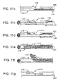
- FIGS. 11a-11g comprises a multi-lumen (i.e. dual-lumen) reentry catheter 1140 having a side-port 1141 and a ramp 1142 to guide reentry of an elongate member 1121 from a sub-intimal space 1180 following sub-intimal dissection.
- the reentry catheter lumens are separated by a tearable sheath 1160 which supports ramp 1142 in a partially actuated configuration, allowing undisturbed passage of a guidewire 1120 through one of the reentry catheter lumens.
- Tearable sheath 1160 may be a thin layer of ePTFE or any other tearable material capable of withstanding the downward force of ramp 1142 without tearing.
- ramp 1142 is not actuated by withdrawing guidewire 1120 from its respective catheter lumen in a proximal direction past side-port 1141 and ramp 1142.
- Ramp 1142 is fully actuated by advancing elongate member 1121 sufficient to tear tearable sheath 1160 (due to it having a larger diameter than guidewire 1120) and thereby remove the support for ramp 1142, whereupon elongate member 1121 can be withdrawn to allow full actuation and then advanced through side-port 1141 for reentry into a vessel 1100 from sub-intimal space 1180.
- an optional outer ring 1143 integrally comprises side port 1141 and ramp 1142 (e.g., cut from a single tube or formed in a common mold) and circumscribes, or is otherwise coupled to the distal end of, multi-lumen reentry catheter 1140.
- multi-lumen reentry catheter 1140 is configured with its own respective side port on its distal end which is in turn aligned with side port 1141.
- ramp 1142 may drop into its actuated configuration upon the withdrawal of elongate member 1120, and piercing catheter 1130 when present in exemplary embodiments, from the distal end of multi-lumen reentry catheter 1140.
- a method of using a device such as described herein comprises the steps of inserting an elongate member into an occluded vessel proximate an occlusion; advancing a piercing catheter over the elongate member to a position proximate the distal end of the elongate member; and applying a longitudinal force to advance the elongate member into the occlusion.
- the piercing catheter when it is proximal to the elongate member, it serves to support the elongate member so that it has sufficient stiffness to cross the occlusion.
- a method comprises the steps of inserting an elongate member 520 into an occluded vessel proximate an occlusion 505; advancing a piercing catheter 530 over the elongate member 520 to a position beyond the distal end of the elongate member 520 such that a tip 532 is formed at the distal end of the piercing catheter 530, and applying a longitudinal force to advance the piercing catheter 530 into the occlusion 505.
- a further embodiment involves reciprocating the elongate member 520 in and out of the chisel's 531 distal end to actuate the chisel 531 between an open tip (See FIG.
- tip 532 is used to pierce the fibrous cap of the occlusion then elongate member 520 (i.e. a guidewire) is pushed through the rest of the occlusion.
- the present invention comprises the steps of inserting an elongate member 920 into an occluded vessel 900 proximate an occlusion 905; advancing the elongate member 920 into the sub-intimal space 980 of the occluded vessel 900 so the distal end of the elongate member 920 has bypassed the occlusion 905; advancing a piercing catheter 930 over the elongate member 920 to a position proximate the distal end of the elongate member 920; advancing a reentry catheter 940 over the piercing catheter 930; retracting the elongate member 920 and piercing catheter 930 to actuate the ramp 942 and; applying a longitudinal force to advance the piercing catheter 930 up the ramp 942 to re-enter the occluded vessel 900 on the distal side of the occlusion 905.
- the present invention comprises the steps of inserting a guidewire 1120 into an occluded vessel 1100 proximate an occlusion 1105; advancing the guidewire into the sub-intimal space 1180 of the occluded vessel 1105 so the distal end 1170 of the elongate member 1120 has bypassed the occlusion 1105; advancing a reentry catheter 1140 with a tearable sheath 1160 over the elongate member 1120 so that the reentry catheter's 1140 distal end is proximate the distal end of the elongate member 1120; withdrawing the guidewire 1120; advancing a larger elongate member 1121 distal the side-port and thereby tearing the tearable sheath 1160; withdrawing the larger elongate member 1121 proximal the side-port 1141 and thereby actuating the ramp 1142; and applying a longitudinal force to advance the larger
- yet another exemplary embodiment comprises the steps of applying a longitudinal force to advance a piercing catheter through any anatomical feature, wherein the piercing catheter comprises: an elongate member; a hollow chisel with proximal and distal ends, wherein the distal end actuates between an open and closed position; wherein the distal end opens when the elongate member passes through the distal end; and wherein the distal end closes to form the tip when the elongate member is removed from the distal end; and a catheter with its distal end attached to the chisel's proximate end such that the catheter and the chisel circumscribe the elongate member.
- Yet another exemplary method comprises an attempted crossing of an occlusion through the lumen of the occluded vessel and abandoning the cross approach and instead performing a sub-intimal dissection to bypass the occlusion.
- An embodiment may comprise inserting an elongate member into an occluded vessel proximate an occlusion; advancing a piercing catheter over the elongate member to a position beyond the distal end of the elongate member such that a tip is formed at the distal end of the piercing catheter; applying a longitudinal force to advance the piercing catheter into the occlusion; withdrawing the piercing catheter proximal the distal end of the elongate member; advancing the elongate member into the sub-intimal space of the occluded vessel distal the occlusion; advancing a piercing catheter over the elongate member to a position proximate the distal end of the elongate member; advancing a reentry
- catheters, piercing catheters, reentry catheters and the like referenced herein may incorporate any of the various aspects described.
- other embodiments comprise using devices and methods described herein to perforate and exit the vessel completely through the perforation site and creating a bypass in neighboring vessel or tissue.
- Other embodiments comprise using devices and methods described herein to pierce grafts or stent-grafts to create fenestrations. Fenestrations to host vessels and/or indwelling devices (grafts and stent-grafts) could be facilitated with this system.
- the flexible nature of the puncturing tool allows for easy and accurate deflection from the host lumen to the vessel wall.
- said medical device has a method of buttressing said device against a vessel, stent and/or stent-graft in order to generate enough force to pierce said vessel, stent, and/or stent-graft.
- Traversing tissue may require the clinician to use some mode of imaging (Ultrasound / Angiography, in which case, the puncturing tool would be configured to be echogenic or radiopaque.
- Still other embodiments may include various coatings to the various structures described herein, such as for example, ePTFE, Heparin, or the like.
- the medical device of the invention may comprise an echogenic and/or radio-opaque material permitting visualizing by medical imagery, particularly by ultrasound and/or radiography, the position of the medical device of the invention.
- the echogenic portion includes an echogenic material comprising a plastic impregnated with sonically reflective particles.
- Radiopaque markers or similar indicia are often used to allow the medical staff to exactly position the medical device using the imagining technology.
- the system of the invention may include some type of radiopaque marker to allow the physician performing the procedure to monitor the progress of the system through the body.
- the system may contain either radiopaque markers or contain radiopaque materials commonly known in the art.
- the markings may also include a radiopaque material to aid in non-invasive visualization or other suitable visualization materials as known in the art.
- radiopaque metallic fibers such as gold, platinum, platinum-tungsten, palladium, platinum-iridium, rhodium, tantalum, or alloys or composites of these metals like may be incorporated into the device, particularly, into the graft, to allow fluoroscopic visualization of the device.
- the systems and methods described herein may be useful in connection with the treatment of coronary artery disease, peripheral vascular diseases, portal hypertension, carotid artery disease, renal vascular hypertension, occlusion of the iliac vessels, subintimal angioplasty (as described in Bolia, et al. Cardiovasc. Intervent. Radiol., 13, 357-363, (1990 )), biopsies, and in situ fenestration of other tissues, amongst other conditions affecting anatomical conduits.
- the present invention may also be useful to pierce grafts or stent-grafts to create fenestrations and to create anatomical passages such as an arterio-venous fistula.
Abstract
Description
- This Patent Application claims priority to and the benefit of Provisional Patent Application Serial No.
61/394,286 - The present invention generally relates to the field of endoluminal products, and more particularly, to the field of percutaneous occlusion crossing systems and methods.
- Cardiovascular disease, including atherosclerosis, is a leading cause of death in the United States. One method for treating atherosclerosis and other forms of vessel lumen narrowing is angioplasty. The objective of angioplasty is to restore adequate blood flow through the affected vessel, which may be accomplished by introducing a treatment catheter within the narrowed lumen of the vessel to dilate it.
- The anatomy of vessels varies widely from patient to patient. Often a patient's vessels are irregularly shaped, highly tortuous and very narrow. The tortuous configuration of the vessels may present difficulties to a clinician in advancement of a treatment catheter to a treatment site. In addition, in some instances, the extent to which the lumen is narrowed at a treatment site is so severe that the lumen is completely or nearly completely obstructed, which may be described as a total occlusion. A chronic total occlusion (CTO) is generally an occlusion that has completely blocked a blood vessel for an extended period of time.
- The tissue composition of a CTO is generally a variable mix of collagenrich plaque, layered thrombus, calcium, and inflammatory cells with fibro-calcific caps at both ends. This fibrous cap may present a surface that is difficult to penetrate with a conventional medical guidewire such that one method of crossing a CTO includes utilizing a stiffer guidewire to create a new channel through the occlusion. Due to the fibrous cap of the CTO, a stiffer guidewire still may not be able to cross it and the distal end of the guidewire may buckle or prolapse within the vessel when force is applied. In addition, a clinician must take care to avoid perforation of the vessel wall when using a stiffer guidewire.
- By way of mere examples, CTOs are often defined as coronary occlusions that have had thrombolysis in myocardial infarction (TIMI) grade flow of 0 or 1 for an estimated duration of at least one month. Available interventional procedures to treat coronary occlusions include coronary angioplasty, e.g., percutaneous transluminal coronary angioplasty (PTCA), and stent placement, e.g., drug-eluting stent placement. These procedures are considered percutaneous because they are performed through a tube or catheter inserted into a blood vessel, rather than through an incision in the chest. However, coronary artery CTOs have historically been some of the most challenging types of blockages to treat with percutaneous interventional procedures because the fibrotic and calcified nature of the CTOs makes passage difficult. As a result, many patients with coronary artery CTOs require coronary artery bypass graft (CABG) surgery to treat the blockage. CTOs are also frequently present in many other locations of the human vascular system, including in peripheral vessels.
- Therefore, a need exists to develop better systems and methods for percutaneous treatment of occlusions, especially with respect to improving the available systems and methods for penetrating and bypassing the occlusion or anatomical blockage, and for incorporating multiple options to recanalize the vessel within a single device.
- In accordance with exemplary embodiments, the present invention comprises systems and methods for penetrating and bypassing chronic total or near total occlusions of vessels through the use of elongate members and specialized catheters, for example, piercing catheters, reentry catheters, and multi-lumen, reentry catheters. The systems and methods described herein may be useful in connection with the treatment of coronary artery disease, peripheral vascular diseases, portal hypertension, carotid artery disease, renal vascular hypertension, subintimal angioplasty, biopsies, in situ fenestration of other tissues, amongst other conditions affecting anatomical conduits. The present invention may also be useful to pierce grafts or stent-grafts to create fenestrations and to create anatomical passages such as an arterio-venous fistula.
- In accordance with an exemplary embodiment of the present invention, a piercing catheter having a distal tip is configured to pierce and thereby cross an occlusion. In accordance with an aspect of this exemplary embodiment, the piercing catheter is configured to perform micro-dissection to cross the occlusion.
- Another embodiment of the present invention comprises a reentry catheter having a side-port and ramp to guide reentry of an inner elongate member from the sub-intimal space following sub-intimal dissection. In an embodiment, upon withdrawing the inner elongate member to the proximal side of the side-port and ramp, the ramp is actuated to direct the inner elongate member through the side-port for reentry into the vessel from the sub-intimal space upon subsequently advancement of the inner elongate member.
- Yet another embodiment of the present invention comprises a multi-lumen reentry catheter having a side-port and ramp to guide reentry of an inner elongate member from the sub-intimal space following sub-intimal dissection. In an embodiment, the reentry catheter lumens are separated by a tearable sheath which supports the ramp in a partially actuated configuration. The ramp is fully actuated by advancing the inner elongate member sufficient to tear the tearable sheath and thereby remove the support for the ramp, whereupon the inner elongate member can be withdrawn to allow full actuation and then advanced through the side-port for reentry into the vessel's true lumen from the sub-intimal space.
- In yet another embodiment, a single device has the capabilities to perform a piercing procedure and a reentry procedure, by incorporating a piercing catheter and a reentry catheter into a single device.
- Exemplary methods are also described herein.
- Persons skilled in the art will appreciate the embodiments described herein may be useful in connection with crossing or creating one or more ducts through a wide variety of anatomical features.
- The exemplary embodiments of the present invention will be described in conjunction with the accompanying drawing figures in which like numerals denote like elements and:
-
FIG. 1 is a cross-sectional view of an occluded vessel showing the three vessel layers; -
FIG. 2 illustrates an elongate member approaching an occlusion in a vessel; -
FIG. 3 illustrates an embodiment of a piercing catheter advancing down an elongate member; -
FIGS. 4a and4b illustrates an enlarged view of a hollow chisel in a position in which the tip is proximate the axis and a cut pattern for strain relief for the hollow member; -
FIGS. 5a-5c illustrate a method of the present invention for crossing an occlusion within a vessel; -
FIG. 6 illustrates an enlarged view of a hollow chisel embodiment in which an elongate member occupies the lumen and positioning the chisel tip such that it is radially spaced apart from the position illustrated inFIG. 4a ; -
FIG. 7 illustrates a method of the present invention for crossing the occlusion through micro-dissection; -
FIG. 8 illustrates an embodiment of a reentry-crossing device in the sub-intimal space; -
FIG. 9a illustrates an elongate member bypassing the occlusion through sub-intimal dissection; -
FIG. 9b illustrates the piercing catheter passed down the elongate member distal the occlusion; -
FIG. 9c illustrates the reentry catheter passed over the piercing catheter; -
FIG. 9d illustrates the piercing catheter and elongate member retracted into the reentry catheter; -
FIG. 9e is an enlarged view of the reentry catheter side-port and illustrates the ramp-door actuated; -
FIG. 9f illustrates the piercing catheter advanced up the ramp after penetrating the vessel wall distal the occlusion; -
FIG. 9g illustrates an elongate member advanced into the vessel distal the occlusion; -
FIG. 10 illustrates a full section view of a reentry catheter showing the ramp-door actuated; -
FIGS. 11a-11g illustrate a method and system of bypassing an occlusion with a dual lumen reentry catheter; and -
FIG. 12 illustrates a reentry catheter in the sub-intimal space. - Persons skilled in the art will readily appreciate that various aspects of the present invention may be realized by any number of methods and apparatuses configured to perform the intended functions. Stated differently, other methods and apparatuses may be incorporated herein to perform the intended functions. It should also be noted that the accompanying drawing figures referred to herein are not all drawn to scale, but may be exaggerated to illustrate various aspects of the present invention, and in that regard, the drawing figures should not be construed as limiting. Finally, although the present invention may be described in connection with various principles and beliefs, the present invention should not be bound by theory.
- In accordance with exemplary embodiments, the present invention comprises systems and methods for penetrating and bypassing chronic total or near total occlusions of vessels through the use of elongate members and specialized catheters, for example, piercing catheters, reentry catheters, and multi-lumen, reentry catheters. The systems and methods described herein may be useful in connection with the treatment of coronary artery disease, peripheral vascular diseases, portal hypertension, carotid artery disease, renal vascular hypertension, amongst other conditions affecting anatomical conduits. The present invention may also be useful to pierce grafts or stent-grafts to create fenestrations and to create anatomical passages such as an arterio-venous fistula.
- As used herein, a "vessel" may be an artery, vein, capillary or the like, or any other anatomical passageway or conduit existing in a healthy subject. As used herein, an "occlusion" may be a total (e.g., a CTO), near total or partial blockage of a vessel. Turning to the drawing figures,
FIG. 1 is a cross-sectional view of anexemplary vessel 100 having anocclusion 105 and havingmultiple layers - As used herein, an "elongate member" is a flexible element having proximal and distal ends and capable of passing through a tortuous vessel, such as a guidewire, catheter, optical fiber, or the like. An exemplary elongate member may comprise a blunt, rounded, or tapered distal tip, to name a few, and may be characterized by varying degrees of stiffness and/or softness, which may further vary along the length of the elongate member. An exemplary elongate member, or any portion thereof, can be hydrophilic or hydrophobic. Additionally, an exemplary elongate member, or any portion thereof, can be comprised of any number of materials including silicone, latex, polyurethane, polyvinyl chloride, polyethylene, nylon, PTFE, ePTFE, stainless steel, nitinol, or any other biocompatible material, including combinations of the foregoing. Said elongate member can be a guidewire, a catheter, or fiber. In one embodiment, said elongate member is a guidewire. In another embodiment said guidewire can be placed into hollow member 333 (
FIG. 3 ) via "over the wire" or by "rapid exchange". Turning back to the drawing figures,FIG. 2 illustrates anelongate member 220 approaching anocclusion 205 in avessel 200. - In accordance with an exemplary embodiment, and with reference to
FIG. 3 , a piercing system 310 (also 510 and 710 inFIGs. 5 and7 respectively) comprises anelongate member 320 slidably housed within and supported by a piercingcatheter 330.Piercing system 310 may be structurally and/or materially configured to cross anocclusion 305 within avessel 300 by applying a continuous or intermittent longitudinal force or rotational (torquing) movement at the proximal end of at least one ofelongate member 320 and piercingcatheter 330. For instance, in exemplary embodiments, piercingcatheter 330 is configured to pierce and penetrateocclusion 305. That is, and as will be discussed below, in some embodiments, piercingcatheter 330 has a shape and/or stiffness sufficient to pierce and penetrate occlusion 305 (or alternatively, through vessel walls), while in other embodiments, piercingcatheter 330 is configured to microdissectocclusion 305. For a point of reference,FIG. 7 illustrates an exemplary embodiment of a piercing catheter microdissecting an occlusion. - In accordance with an exemplary embodiment, and with continued reference to
FIG. 3 , piercingcatheter 330 may comprise ahollow chisel 331 having atip 332 and being coupled to the distal end of ahollow member 333. Briefly, as used herein, "hollow" means a passage or space therein which can allow the passage of another object. In accordance with various aspects of this exemplary embodiment, a plurality ofhollow chisel 331,tip 332 andhollow member 333 may be comprised of the same material (e.g., cut from a single tube or formed in a common mold). Moreover, any ofhollow chisel 331,tip 332 andhollow member 333 and/or the piercingcatheter 330 may be coated with an ePTFE film. In exemplary embodiments,elongate member 320 is slidably housed within and supported byhollow member 333. In exemplary embodiments,elongate member 320 is axially movable along the longitudinal axis ofhollow member 333 andhollow chisel 331 such thattip 332 is laterally displaced by axial displacement ofelongate member 320, for instance, axial displacement on the order of 1 mm. For example,tip 332 may be laterally displaced (e.g., opened and closed or any position in between) in response to selective axial displacement ofelongate member 320, between a first position, in which tip 332 is disposed proximal to the axis, and a second position, in which tip 332 is generally radially spaced apart from the first position. For point of reference,FIG. 6 illustrates anembodiment 630 with thehollow chisel 631 and tip 632 ofhollow member 633 in a second position (withelongate member 620 moved distally) andFIG. 4a illustrates anembodiment 430 with thetip 432 in a first position. - In exemplary embodiments,
hollow member 333 is an elongate member, as that term has been defined herein, configured to houseelongate member 320 along its longitudinal axis. The outer diameter ofhollow member 333 should permit its passage through lumen ofvessel 300 and the inner diameter ofhollow member 333 should permit passage ofelongate member 320. In exemplary embodiments, the outer diameter ofhollow member 333 is from about 0.015 to about 0.055 inches, more preferably from about 0.025 to about 0.045 inches, and most preferably about 0.035 inches. In exemplary embodiments, the inner diameter ofhollow member 333 is from about 0.006 to about 0.022 inches, more preferably from about 0.010 to about 0.016 inches, and most preferably about 0.016 inches. - In accordance with exemplary embodiments of the present invention,
hollow chisel 331 is coupled to the distal end ofhollow member 333. The coupling may occur at or near the point of articulation oftip 332 or further down a chisel shaft (not shown) ofhollow chisel 331. In accordance with an aspect of an exemplary embodiment comprising a chisel shaft, an outer surface of the chisel shaft may be spiral-cut for added flexibility, for example, starting at from about 2 to about 3mm proximal to the point of articulation oftip 332. The dimensions ofhollow chisel 331 at its proximal end may be larger or smaller than the dimensions ofhollow member 333 at its distal end. That being said, in a preferred embodiment, the diameters are substantially the same to generally align the longitudinal axes forelongate member 320 to travel. - In accordance with exemplary embodiments of the present invention is illustrated by
Fig 4b . In this embodiment, flexibility of the distal region of thehollow member 433 has been improved by cutting openings throughhollow member 433. Several cut patterns can be used. In one embodiment, the cut pattern is a series ofsemi-circular kerfs 450 laid out in a helical pattern on the distal end of the catheter. In another embodiment, length of thesemi-circular kerfs 450 is shortened toward the proximal end of the helical pattern. This serves as a strain relief. Several other cut shapes are possible. These include straight kerfs and rectangular or partial rectangular kerfs. It is possible to wrap the cut region with film to allow passage of contrast fluid through hollow member and out its distal end (or out some ofkerfs 450 if they are left unwrapped). The film wrap does not hinder the flexibility created by the cuts. In one embodiment said film comprises ePTFE. Flexibility ofhollow member 433 may be altered (alone or in combination with placement of kerfs 450) by varying the wall thickness ofmember 433 and/or varying the thermal treatment applied to hollow member. As is known in the art, heat treatment of metals may alter their flexibility. In various embodiments,tip 432 may possess different shapes. For example,tip 432 may feature a pointed terminal end such as that shown inFig. 4a . In certain embodiments,tip 432 may have a more rounded end. In various embodiments,hollow member 433 may comprise different shaped terminal ends on both its ends. Such configurations allow the clinician to choose tip end shape or change the tip used during a procedure by removinghollow member 433 and inserting the opposite end ofhollow member 433. - In various embodiments,
tip 332 comprises one or a plurality of separate elements at its distal end, at least one of which is moveable in response to selective axial displacement ofelongate member 320. For example,tip 332 may comprise one, two, three, four, five, six or any other suitable number of separate elements at its distal end. For the avoidance of doubt, such separate elements may emanate from a unitary structure such as a ring at or near its proximal end.Tip 332 itself may be generally smooth or modified with serrations, barbs, hooks, anchors or the like. - In different embodiments,
tip 332 may taper or otherwise come to a sharp point, a straight wedge, a curved wedge, or any other end that facilitates piercing and/or penetratingocclusion 305.Tip 332 may be comprised of a shape memory material such as nitinol to facilitate its articulation. In exemplary embodiments, the shape memory material may permit the tip to regain its closed position form after withdrawal ofelongate member 320 from its lumen. Other modes of tip reformation could be through a spring-loaded micro hinge, a collapsible mesh, or any other structures which permit the tip to regain its closed position form upon withdrawal ofelongate member 320 from its lumen. In another embodiment, said shape memory alloy is selected from the group consisting of spring steel, Eligloy and carbon fiber composite. - In exemplary embodiments,
tip 332 is biased in a closed position whenelongate member 320 is withdrawn out of the lumen ofhollow chisel 331. In related embodiments,elongate member 320 is reciprocated in and out of the lumen ofhollow chisel 331 to articulatetip 332 between a closed tip and an open tip configuration, for example, to perform micro-dissection. The closed and open configurations could alternate between a sharp tip and a blunt tip, respectively, or any shaped tip which facilitates micro-dissection. In one embodiment, said elongate member is reciprocated manually or automatically using a device that attaches to the elongate member and reciprocates said elongate member. - Exemplary embodiments of the present invention provide reentry systems configured to bypass an occlusion. Similarly, exemplary embodiments of the present invention provide reentry systems configured to cross an occlusion as described above, and also to bypass an occlusion in the event crossing by piercing and penetrating is unsuccessful. Bypassing an occlusion in exemplary embodiments comprises sub-intimal dissection. In general, embodiments of the present invention may facilitate initial entry or reentry of an elongate member into a vessel or other anatomical feature.
- In accordance with exemplary embodiments, and now with reference to
FIGS. 8 and10 , areentry system 850 comprises anelongate member 820 optionally disposed within and moveable along the longitudinal axis and through the lumen of a piercingcatheter 830, and areentry catheter 840.Reentry catheter 840 in turn comprises aside port 841 and aramp 842, both near its distal end, optionally anouter ring 843, and ahollow member 844, wherein at least one ofelongate member 820 and piercingcatheter 830 is disposed within and moveable along the longitudinal axis and through the lumen ofouter ring 843 andhollow member 844 and can be directed to exit throughside port 841 by way oframp 842. The length between the distal tip ofreentry catheter 840 and the distal edge ofside port 841 may be varied as clinically required. The stiffness and "torqueability" ofreentry catheter 840 may be varied by altering the strength of its materials, the coil configuration (if it is of coiled construction), the braid angle and/or the pick count (if it is of braided construction), and/or by using more or less overwrapping material. - In accordance with various aspects of exemplary embodiments, side-
port 841 remains blocked byramp 842 when at least one ofelongate member 820 and piercingcatheter 830 is disposed withinreentry system 850 and extends distal to side-port 841. Whenelongate member 820 and piercingcatheter 830 are present in exemplary embodiments, are both retracted proximal to side-port 841,ramp 842 is actuated thereby openingside port 841 and presentingramp 842 to direct reentry ofelongate member 820 and piercingcatheter 830 back into the lumen of avessel 800 from the sub-intimal space following sub-intimal dissection. Sub-intimal dissection may be performed by techniques known to those skilled in the art usingelongate member 820 or piercingcatheter 830. For example,elongate member 820 may comprise a flexible distal end configured to fold over on itself upon meeting resistance from anocclusion 805 and be displaced laterally into the sub-intimal space for subintimal dissection. - In exemplary embodiments,
ramp 842 is maintained in a blocking configuration by one ofelongate member 820 and piercingcatheter 830 but is biased to actuate and drop to present itself for directing reentry. Such bias may be accomplished using a shape memory material such as nitinol or any other material or device that permitsramp 842 to drop into its actuated configuration upon the withdrawal ofelongate member 820, and piercingcatheter 830 when present in exemplary embodiments, from the distal end ofreentry catheter 840. - In some embodiments,
side port 841 and ramp 842 are integral withhollow member 844. In other embodiments, optionalouter ring 843 integrally comprisesside port 841 and ramp 842 (e.g., cut from a single tube or formed in a common mold) and circumscribes, or is otherwise coupled to the distal end of,hollow member 844. In accordance with an aspect of an exemplary embodiment comprising a circumscribingouter ring 843,hollow member 844 is configured with its own respective side port on its distal end which is in turn aligned withside port 841. As above,ramp 842 may drop into its actuated configuration upon the withdrawal ofelongate member 820, and piercingcatheter 830 when present in exemplary embodiments, from the distal end ofreentry catheter 840. - In yet other exemplary embodiments,
ramp 842 may be pivotally coupled tohollow member 844 withinside port 841 to drop into its actuated configuration upon the withdrawal ofelongate member 820 and piercingcatheter 830 from the distal end ofreentry catheter 840. Such embodiments may comprise a spring and/or a hinge. - In various embodiments ramp 842 may be actuated mechanically. For example, ramp may be moved from its closed to open (i.e., angled) position by use of attached pull wires. In another example, ramp 842 may be actuated by axial motion between co-radial inner and outer tubes where one edge or portion of the ramp is attached to one tube and another edge or portion is attached to the other tube. In various embodiments, such relative axial motion could be used to actuate a ramp with spring or memory characteristics whereby the ramp may be formed in the outer tube and upon removal of the inner tube proximate the ramp, the ramp moves into position. In other embodiments,
ramp 842 may be moved (or allowed to move) into place by torquing or twisting a co-radial tube assembly. In yet other exemplary embodiments,ramp 842 may comprise an inflatable member, e.g., the ramp is allowed to move into position by either being forced into such position on inflation of a proximally-located bladder or the inverse, i.e., the ramp moves into position by deflation of such a bladder. In various embodiments,ramp 842 may be comprised by the inflatable member itself. In various embodiments,ramp 842 may be actuated hydraulically by directing a stream of fluid (e.g., saline) against some portion of the ramp. - The angle of reentry for devices of the present invention, relative to the longitudinal axis of the reentry catheter 840 (and relative to the longitudinal axis of the vessel), may be varied by design to suit clinician preference. These preferences are typically driven by a clinician's desire to accomplish reentry without piercing the vessel wall across the lumen from the reentry site (a risk when reentry angles are high) and accuracy in reentry at a desired target (a challenge when angles are low). An angle between about 25 to about 50 degrees may be used in certain cases. An angle of between about 35 to about 45 degrees may be used for certain treatment procedures. In another embodiment, said angle is about 25, about 30, about 40, about 45, or about 50 degrees. The angle of reentry may result from one or more design factors. Angle of
ramp 842 when moved into position is one such factor but another factor is the flexibility of hollow member 433 (as seen inFIG. 4b ) as described above. - The dimensions of
reentry catheter 840 should generally be sufficient to permit passage ofelongate member 820 and optionally piercingcatheter 830. - In exemplary embodiments,
reentry catheter 840 is configured to permit passage of an elongate member having an outer diameter of from about 0.010 to about 0.055", more preferably from about 0.025 to about 0.045", and most preferably about 0.040". In exemplary embodiments, the outer diameter ofreentry system 850 is from about 0.025 to about 0.10" and more preferably about 0.05". - As alluded to above, and with momentary reference to
FIG. 12 , an exemplary reentry system comprises any elongate member, as that term has been defined herein, disposed within and moveable along the longitudinal axis and through the lumen of areentry catheter 1240.Reentry catheter 1240 in turn comprises aside port 1241 and aramp 1242, both near its distal end, optionally anouter ring 1243, and a hollow member, wherein the elongate member is disposed within and moveable along the longitudinal axis and through the lumen ofouter ring 1243 andhollow member 1244 and can be directed to exit throughside port 1241 by way oframp 1242. - Yet another embodiment of the present invention, and now with reference to
FIGS. 11a-11g , comprises a multi-lumen (i.e. dual-lumen)reentry catheter 1140 having a side-port 1141 and aramp 1142 to guide reentry of anelongate member 1121 from asub-intimal space 1180 following sub-intimal dissection. In an embodiment, the reentry catheter lumens are separated by atearable sheath 1160 which supportsramp 1142 in a partially actuated configuration, allowing undisturbed passage of aguidewire 1120 through one of the reentry catheter lumens.Tearable sheath 1160 may be a thin layer of ePTFE or any other tearable material capable of withstanding the downward force oframp 1142 without tearing. In an embodiment,ramp 1142 is not actuated by withdrawing guidewire 1120 from its respective catheter lumen in a proximal direction past side-port 1141 andramp 1142.Ramp 1142 is fully actuated by advancingelongate member 1121 sufficient to tear tearable sheath 1160 (due to it having a larger diameter than guidewire 1120) and thereby remove the support forramp 1142, whereuponelongate member 1121 can be withdrawn to allow full actuation and then advanced through side-port 1141 for reentry into avessel 1100 fromsub-intimal space 1180. - As above, in some embodiments an optional
outer ring 1143 integrally comprisesside port 1141 and ramp 1142 (e.g., cut from a single tube or formed in a common mold) and circumscribes, or is otherwise coupled to the distal end of,multi-lumen reentry catheter 1140. In accordance with an aspect of an this exemplary embodiment,multi-lumen reentry catheter 1140 is configured with its own respective side port on its distal end which is in turn aligned withside port 1141. Also as above,ramp 1142 may drop into its actuated configuration upon the withdrawal ofelongate member 1120, and piercing catheter 1130 when present in exemplary embodiments, from the distal end ofmulti-lumen reentry catheter 1140. - In an embodiment, a method of using a device such as described herein comprises the steps of inserting an elongate member into an occluded vessel proximate an occlusion; advancing a piercing catheter over the elongate member to a position proximate the distal end of the elongate member; and applying a longitudinal force to advance the elongate member into the occlusion.
- In various embodiments, when the piercing catheter is proximal to the elongate member, it serves to support the elongate member so that it has sufficient stiffness to cross the occlusion.
- In accordance with another embodiment and with reference to
FIG. 5a through 5c , a method comprises the steps of inserting anelongate member 520 into an occluded vessel proximate anocclusion 505; advancing a piercingcatheter 530 over theelongate member 520 to a position beyond the distal end of theelongate member 520 such that atip 532 is formed at the distal end of the piercingcatheter 530, and applying a longitudinal force to advance the piercingcatheter 530 into theocclusion 505. A further embodiment involves reciprocating theelongate member 520 in and out of the chisel's 531 distal end to actuate thechisel 531 between an open tip (SeeFIG. 6 ) and closed tip (SeeFIG. 4a ) as the piercingcatheter 530 is advanced into theocclusion 505. In another embodiment,tip 532 is used to pierce the fibrous cap of the occlusion then elongate member 520 (i.e. a guidewire) is pushed through the rest of the occlusion. - In accordance with another embodiment and with reference to
FIG. 9a-9g , the present invention comprises the steps of inserting anelongate member 920 into anoccluded vessel 900 proximate anocclusion 905; advancing theelongate member 920 into thesub-intimal space 980 of theoccluded vessel 900 so the distal end of theelongate member 920 has bypassed theocclusion 905; advancing a piercingcatheter 930 over theelongate member 920 to a position proximate the distal end of theelongate member 920; advancing areentry catheter 940 over the piercingcatheter 930; retracting theelongate member 920 and piercingcatheter 930 to actuate theramp 942 and; applying a longitudinal force to advance the piercingcatheter 930 up theramp 942 to re-enter theoccluded vessel 900 on the distal side of theocclusion 905. - In accordance with an exemplary embodiment and with reference to
FIG. 11a -11f , the present invention comprises the steps of inserting aguidewire 1120 into anoccluded vessel 1100 proximate anocclusion 1105; advancing the guidewire into thesub-intimal space 1180 of theoccluded vessel 1105 so thedistal end 1170 of theelongate member 1120 has bypassed theocclusion 1105; advancing areentry catheter 1140 with atearable sheath 1160 over theelongate member 1120 so that the reentry catheter's 1140 distal end is proximate the distal end of theelongate member 1120; withdrawing theguidewire 1120; advancing alarger elongate member 1121 distal the side-port and thereby tearing thetearable sheath 1160; withdrawing thelarger elongate member 1121 proximal the side-port 1141 and thereby actuating theramp 1142; and applying a longitudinal force to advance thelarger elongate member 1121 up theramp 1142 to re-enter theoccluded vessel 1100 on thedistal side 1170 of theocclusion 1105. Thelarger elongate member 1121 could be a piercing catheter (See embodiment 310). - And yet another exemplary embodiment comprises the steps of applying a longitudinal force to advance a piercing catheter through any anatomical feature, wherein the piercing catheter comprises: an elongate member; a hollow chisel with proximal and distal ends, wherein the distal end actuates between an open and closed position; wherein the distal end opens when the elongate member passes through the distal end; and wherein the distal end closes to form the tip when the elongate member is removed from the distal end; and a catheter with its distal end attached to the chisel's proximate end such that the catheter and the chisel circumscribe the elongate member.
- And yet another exemplary method comprises an attempted crossing of an occlusion through the lumen of the occluded vessel and abandoning the cross approach and instead performing a sub-intimal dissection to bypass the occlusion. An embodiment may comprise inserting an elongate member into an occluded vessel proximate an occlusion; advancing a piercing catheter over the elongate member to a position beyond the distal end of the elongate member such that a tip is formed at the distal end of the piercing catheter; applying a longitudinal force to advance the piercing catheter into the occlusion; withdrawing the piercing catheter proximal the distal end of the elongate member; advancing the elongate member into the sub-intimal space of the occluded vessel distal the occlusion; advancing a piercing catheter over the elongate member to a position proximate the distal end of the elongate member; advancing a reentry catheter over the piercing catheter, retracting the elongate member and piercing catheter to actuate the ramp; and applying a longitudinal force to advance the piercing catheter up the ramp to re-enter the occluded vessel on the distal side of the occlusion.
- In various embodiments, catheters, piercing catheters, reentry catheters and the like referenced herein may incorporate any of the various aspects described. Moreover, other embodiments comprise using devices and methods described herein to perforate and exit the vessel completely through the perforation site and creating a bypass in neighboring vessel or tissue. Other embodiments comprise using devices and methods described herein to pierce grafts or stent-grafts to create fenestrations. Fenestrations to host vessels and/or indwelling devices (grafts and stent-grafts) could be facilitated with this system. The flexible nature of the puncturing tool allows for easy and accurate deflection from the host lumen to the vessel wall. Forward axial deflection would then cause the puncturing tool to pierce the endoprosthesis and/or vessel. Continued forward movement would allow the puncturing tool to traverse tissue and possible even re-enter another vessel lumen for a specific purpose such as constructing an A-V Fistula or a TIPS procedure. In one embodiment, said medical device has a method of buttressing said device against a vessel, stent and/or stent-graft in order to generate enough force to pierce said vessel, stent, and/or stent-graft.
- Traversing tissue may require the clinician to use some mode of imaging (Ultrasound / Angiography, in which case, the puncturing tool would be configured to be echogenic or radiopaque. Still other embodiments may include various coatings to the various structures described herein, such as for example, ePTFE, Heparin, or the like.
- In another embodiment, the medical device of the invention may comprise an echogenic and/or radio-opaque material permitting visualizing by medical imagery, particularly by ultrasound and/or radiography, the position of the medical device of the invention. The echogenic portion includes an echogenic material comprising a plastic impregnated with sonically reflective particles.
- Radiopaque markers or similar indicia are often used to allow the medical staff to exactly position the medical device using the imagining technology. The system of the invention may include some type of radiopaque marker to allow the physician performing the procedure to monitor the progress of the system through the body. The system may contain either radiopaque markers or contain radiopaque materials commonly known in the art. The markings may also include a radiopaque material to aid in non-invasive visualization or other suitable visualization materials as known in the art. In addition, one or more radiopaque metallic fibers, such as gold, platinum, platinum-tungsten, palladium, platinum-iridium, rhodium, tantalum, or alloys or composites of these metals like may be incorporated into the device, particularly, into the graft, to allow fluoroscopic visualization of the device.
- Features of the known art that could be incorporated into the present invention(s) include steerable catheter(s) and the use of a contrast agent delivered through the support catheter's lumen to confirm reentry.
- The systems and methods described herein may be useful in connection with the treatment of coronary artery disease, peripheral vascular diseases, portal hypertension, carotid artery disease, renal vascular hypertension, occlusion of the iliac vessels, subintimal angioplasty (as described in Bolia, et al. Cardiovasc. Intervent. Radiol., 13, 357-363, (1990)), biopsies, and in situ fenestration of other tissues, amongst other conditions affecting anatomical conduits. The present invention may also be useful to pierce grafts or stent-grafts to create fenestrations and to create anatomical passages such as an arterio-venous fistula.
- The foregoing disclosure is merely illustrative of the present invention and is not intended to be construed as limiting the invention. Although one or more embodiments of the present invention have been described, persons skilled in the art will readily appreciate that numerous modifications could be made without departing from the spirit and scope of the present invention. As such, it should be understood that all such modifications are intended to be included within the scope of the present invention.
- The invention shall now be described with reference to the following clauses:
- Clause 1. A medical device comprising:
- a catheter with proximal and distal ends;
- a hollow chisel having a chisel passage therein, having a proximal and distal end, with a tip at the distal end, wherein the chisel's proximal end is proximate to the catheter's distal end; and
- an elongate member axially movable along the longitudinal axis of the catheter and chisel,
- wherein the tip is movable, in response to selective axial displacement of the elongate member, between a first position, in which the tip is disposed proximal to the axis, and a second position, in which the tip is spaced apart from the first position.
- Clause 2. The medical device of clause 1, wherein the tip has at least two portions, at least one of which is moveable in response to selective axial displacement of the elongate member.
-
Clause 3. The medical device system of clause 2, wherein when the elongate member is withdrawn out of the chisel passage, a sharp tip forms. - Clause 4. The medical device system of clause 1, wherein the elongate member can be reciprocated in and out of the chisel's distal end to actuate the chisel between a sharp tip and a blunt tip.
- Clause 5. The medical device system of clause 1, wherein when the elongate member is pushed through and out of the distal end of the chisel, the tip opens to generally conform to the outer diameter of the wire.
- Clause 6. The medical device system of clause 1, wherein when the elongate member is pushed out of the distal end of the chisel, the catheter and chisel together comprise a support catheter.
- Clause 7. The medical device system of clause 1, wherein the chisel comprises a shape memory material.
- Clause 8. The medical device system of clause 7, wherein the shape memory material is nitinol.
- Clause 9. The medical device system of clause 1, wherein the elongate member is a guidewire, a catheter, or fiber.
- Clause 10. A medical device comprising:
- a piercing catheter;
- an elongate member moveable along the longitudinal axis of the piercing catheter; and
- a re-entry catheter, comprising a side port near the distal end, wherein the piercing catheter or elongate member can move through the side port.
- Clause 11. The medical device of clause 10, wherein the re-entry catheter comprises a ramp near the distal end, wherein when the ramp is not actuated, the side port is closed and when the ramp is actuated the side port opens and the ramp is presented for directing the piercing catheter or elongate member through the side port.
- Clause 12. The medical device system of clause 11, wherein
the ramp is not actuated when the distal ends of the elongate member and piercing catheter are distal to the side port, and
the ramp is actuated when the distal ends of the elongate member and piercing catheter are proximal to the side port. - Clause 13. The medical device system of clause 10, wherein when an elongate member is pushed through and out of the distal end of the piercing catheter, the piercing catheter becomes a support catheter.
- Clause 14. The medical device of any clause 10, wherein the piercing catheter comprises a catheter with proximal and distal ends; and
a hollow chisel having a chisel passage therein, with proximal and distal ends, having a tip at the distal end, wherein the chisel's proximal end is proximate to the catheter's distal end,
wherein the tip is movable, in response to selective axial displacement of the elongate member, between a first position, in which the tip is disposed proximal to the axis, and a second position, in which the tip is spaced apart from the first position. - Clause 15. The medical device of clause 14, wherein the elongate member is removed from the chisel passage and the chisel is actuated to form a sharp tip.
- Clause 16. The medical device system of clause 13, wherein the support catheter is of substantially rounded cross section along its length.
- Clause 17. The medical device system of clause 10, wherein the ramp comprises a shape memory material.
- Clause 18. The medical device system of clause 17, wherein the shape memory material is nitinol.
- Clause 19. The medical device system of clause 10, wherein the elongate member is a guidewire, a catheter, or fiber.
- Clause 20. A medical device comprising:
- an elongate member; and
- a re-entry catheter, comprising a side port and a ramp near the distal end, wherein when the ramp is not actuated, the side port is closed, and when the ramp is actuated, the side port opens and the ramp is presented for directing the elongate member through the side port.
- Clause 21. The medical device of clause 20, wherein the elongate member is a guidewire, catheter, or fiber.
- Clause 22. The medical device of clause 21, wherein the catheter is a piercing catheter.
- Clause 23. The medical device of clause 20, wherein the re-entry catheter has a semi- actuated ramp, which does not fully actuate upon removal of a guidewire.
- Clause 24. The medical device of clause 23, wherein the ramp is fully actuated by an elongate member of larger diameter than a guidewire.
- Clause 25. The medical device of clause 24, wherein the ramp is fully actuated by an elongate member sufficiently broad in diameter to tear a tearable sheath.
- Clause 26. A method of crossing an occlusion comprising:
- inserting an elongate member into an occluded vessel proximate an occlusion; advancing a piercing catheter over the elongate member to a position proximate the distal end of the elongate member, wherein the piercing catheter comprises:
- a hollow chisel having a chisel passage therein, with proximal and distal ends, wherein the distal end actuates between an open and closed position, wherein the distal end opens when the elongate member passes through the distal end, wherein the distal end closes to form a tip when the elongate member is removed from the distal end; and
- a catheter with its distal end attached to the chisel's proximate end such that the catheter and the chisel circumscribe the elongate member; and
- applying a longitudinal force to advance at least one of the elongate member and piercing catheter into the occlusion.
- inserting an elongate member into an occluded vessel proximate an occlusion; advancing a piercing catheter over the elongate member to a position proximate the distal end of the elongate member, wherein the piercing catheter comprises:
- Clause 27. The method of clause 26, wherein the elongate member is a guidewire, a catheter, or fiber.
- Clause 28. The method of clause 26, wherein the chisel comprises a shape memory alloy.
- Clause 29. The method of clause 28, wherein the shape memory alloy is nitinol.
- Clause 30. The method of clause 26, wherein the tip has at least two portions, at least one of which is moveable in response to axial displacement of the elongate member.
- Clause 31. The method of clause 26, wherein when the elongate member is withdrawn out of the chisel's distal end, a sharp tip forms.
- Clause 32. The method of clause 26, wherein the elongate member can be reciprocated in and out of the chisel lumen to actuate the chisel between a sharp tip and a blunt tip.
- Clause 33. The method of clause 26, wherein when the elongate member is pushed through and out of the distal end of the chisel, the chisel tip opens to generally conform to the outer diameter of the wire.
- Clause 34. A method of crossing an occlusion comprising:
- inserting an elongate member into an occluded vessel proximate an occlusion; advancing the elongate member into a sub-intimal space of the occluded vessel on a proximal side of the occlusion and to a distal side of the occlusion;
- advancing a piercing catheter over the elongate member to a position proximate the distal end of the elongate member, wherein the piercing catheter comprises:
- a hollow chisel having a chisel passage therein, with proximal and distal ends, wherein the distal end actuates between an open and closed position, wherein the distal end opens when the elongate member passes through the distal end, wherein the distal end closes to form a tip when the elongate member is removed from the distal end;
- a catheter with its distal end attached to the chisel's proximate end such that the catheter and the chisel circumscribe the elongate member;
- advancing a side-port catheter over the piercing catheter,
- wherein the side-port catheter has a side port and a ramp near the distal end; wherein when the ramp is not actuated, the side port is closed and when the ramp is actuated the side port opens and the ramp is presented for directing the piercing catheter or elongate member through the side port; and
- wherein the ramp is actuated when the distal end of the elongate member and piercing catheter is proximate the side port;
- retracting the elongate member and piercing catheter to actuate the ramp; and applying a longitudinal force to advance the piercing catheter up the ramp to reenter the occluded vessel on a distal side of the occlusion.
- Clause 35. The method of clause 34, wherein the elongate member is a guidewire, a catheter, or fiber.
- Clause 36. The method of clause 34, wherein the tip has at least two portions, at least one of which is moveable in response to axial displacement of the elongate member.
- Clause 37. The method of clause 34, wherein when the elongate member is withdrawn out of the chisel's distal end, a sharp tip forms.
- Clause 38. The method of clause 34, wherein the elongate member can be reciprocated in and out of the chisel passage to actuate the chisel between a sharp tip and a blunt tip.
- Clause 39. The method of clause 34, wherein when the elongate member is pushed through and out of the distal end of the chisel, the chisel tip opens to generally conform to the outer diameter of the wire.
- Clause 40. The method of clause 34, wherein the chisel comprises a shape memory alloy.
- Clause 41. The method of clause 40, wherein the shape memory alloy is nitinol.
- Clause 42. A method of forming an anatomical corridor comprising:
- applying a longitudinal force to advance a piercing catheter through an anatomical feature, wherein the piercing catheter comprises:
- an elongate member;
- a hollow chisel having a passage therein, with proximal and distal ends, wherein the distal end actuates between an open and closed position, wherein the distal end opens when the elongate member passes through the distal end, wherein the distal end closes to form the tip when the elongate member is removed from the distal end; and
- a catheter with its distal end attached to the chisel's proximate end such that the catheter and the chisel circumscribe the elongate member.
- applying a longitudinal force to advance a piercing catheter through an anatomical feature, wherein the piercing catheter comprises:
- Clause 43. The method of clause 42, further comprising reciprocating the elongate member in and out of the chisel's distal end to actuate the chisel between a sharp tip and blunt tip as the catheter is advanced through the anatomical feature.
- Clause 44. The method of clause 42, wherein the elongate member is a guidewire, a catheter, or fiber.
- Clause 45. The method of clause 42, wherein the chisel comprises a shape memory alloy.
- Clause 46. The method of clause 45, wherein the shape memory alloy is nitinol.
- Clause 47. The method of clause 42, wherein the tip has at least two portions, at least one of which is moveable in response to axial displacement of the elongate member.
- Clause 48. The method of clause 42, wherein when the elongate member is withdrawn out of the chisel's distal end, a sharp tip forms.
- Clause 49. The method of clause 42, wherein the elongate member can be reciprocated in and out of the chisel passage to actuate the chisel between a sharp tip and a blunt tip.
- Clause 50. The method of clause 42, wherein when the elongate member is pushed through and out of the distal end of the chisel, the chisel tip opens to generally conform to the outer diameter of the wire.
- Clause 51. The method of clause 42, wherein when the elongate member is pushed through and out of the distal end of the chisel, the chisel tip opens to generally conform to the outer diameter of the wire.
- Clause 52. A method of sub-intimal dissection of a vessel comprising:
- inserting a guidewire into an occluded vessel proximate an occlusion;
- advancing the guidewire into the sub-intimal space of the occluded vessel so the distal end of the elongate member has bypassed the occlusion;
- advancing a reentry catheter with a tearable sheath over the elongate member so that the reentry catheter's distal end is proximate the distal end of the elongate member;
- withdrawing the guidewire;
- advancing a larger elongate member distal the side-port and thereby tearing the tearable sheath;
- withdrawing the larger elongate member proximal the side-port and thereby actuating the ramp; and
- applying a longitudinal force to advance the larger elongate member up the ramp.
- Clause 53. A method of perforating a vessel comprising:
- inserting a guidewire into a vessel proximate a perforation site;
- advancing a reentry catheter with a tearable sheath over the elongate member so that the reentry catheter's distal end is proximate the distal end of the elongate member;
- withdrawing the guidewire;
- advancing a larger elongate member distal the side-port and thereby tearing the tearable sheath;
- withdrawing the larger elongate member proximal the side-port and thereby actuating the ramp; and
- applying a longitudinal force to advance the larger elongate member up the ramp to the perforation site.
- Clause 54. The method of claims 52, wherein the larger elongate member is a piercing catheter.
- Clause 55. A method of percutaneous treatment of an occlusion comprising:
- inserting an elongate member into an occluded vessel proximate an occlusion; advancing a piercing cattteter over the elongate member to a position beyond the distal end of the elongate member such that a tip is formed at the distal end of the piercing catheter, wherein the piercing catheter comprises:
- a hollow chisel having a passage therein, with proximal and distal ends, wherein the distal end actuates between an open and closed position, wherein the distal end opens when the elongate member passes through the distal end, wherein the distal end closes to form the tip when the elongate member is removed from the distal end; and
- a catheter with its distal end attached to the chisel's proximate end such that the catheter and the chisel circumscribe the elongate member;
- applying a longitudinal force to advance the piercing catheter into the occlusion; withdrawing the piercing catheter proximal the distal end of the elongate member;
- advancing the elongate member into a sub-intimal space of the occluded vessel on a proximal side of the occlusion and to a distal side of the occlusion; advancing a piercing catheter over the elongate member to a position proximate the distal end of the elongate member;
- advancing a reentry catheter over the piercing catheter,
- wherein the reentry catheter has a side port and a ramp near the distal end;
- wherein when the ramp is not actuated, the side port is closed and when the ramp is actuated the side port opens and the ramp is presented for directing the piercing catheter or elongate member through the side port; and wherein the ramp is actuated when the distal end of elongate member and piercing catheter is proximate the side port;
- retracting the elongate member and piercing catheter to actuate the ramp; and applying a longitudinal force to advance the piercing catheter up the ramp to reenter the occluded vessel on a distal side of the occlusion.
- inserting an elongate member into an occluded vessel proximate an occlusion; advancing a piercing cattteter over the elongate member to a position beyond the distal end of the elongate member such that a tip is formed at the distal end of the piercing catheter, wherein the piercing catheter comprises:
- Clause 56. A method of perforating a vessel comprising:
- inserting a guidewire into a vessel proximate a perforation site;
- advancing a reentry catheter comprising a distal end side-port and ramp over the elongate member so that the reentry catheter's distal end is proximate the distal end of the elongate member; advancing an elongate member distal the side-port; withdrawing the elongate member and guidewire proximal the side-port and thereby actuating the ramp; and
- applying a longitudinal force to advance the elongate member up the ramp to the perforation site.
- Clause 57. The method of clause 56, wherein the elongate member is a piercing catheter
Claims (10)
- A medical device comprising:a piercing catheter;an elongate member moveable along the longitudinal axis of the piercing catheter; anda re-entry catheter, comprising a side port near the distal end, wherein the piercing catheter or elongate member can move through the side port.
- The medical device of claim 1, wherein the re-entry catheter comprises a ramp near the distal end, wherein when the ramp is not actuated, the side port is closed and when the ramp is actuated the side port opens and the ramp is presented for directing the piercing catheter or elongate member through the side port.
- The medical device system of claim 2, wherein
the ramp is not actuated when the distal ends of the elongate member and piercing catheter are distal to the side port, and
the ramp is actuated when the distal ends of the elongate member and piercing catheter are proximal to the side port. - The medical device system of claim 1, wherein when an elongate member is pushed through and out of the distal end of the piercing catheter, the piercing catheter becomes a support catheter.
- The medical device of any claim 1, wherein the piercing catheter comprises a catheter with proximal and distal ends; and
a hollow chisel having a chisel passage therein, with proximal and distal ends, having a tip at the distal end, wherein the chisel's proximal end is proximate to the catheter's distal end,
wherein the tip is movable, in response to selective axial displacement of the elongate member, between a first position, in which the tip is disposed proximal to the axis, and a second position, in which the tip is spaced apart from the first position. - The medical device of claim 5, wherein the elongate member is removed from the chisel passage and the chisel is actuated to form a sharp tip.
- The medical device system of claim 4, wherein the support catheter is of substantially rounded cross section along its length.
- The medical device system of claim 1, wherein the ramp comprises a shape memory material.
- The medical device system of claim 8, wherein the shape memory material is nitinol.
- The medical device system of claim 1, wherein the elongate member is a guidewire, a catheter, or fiber.
Applications Claiming Priority (4)
| Application Number | Priority Date | Filing Date | Title |
|---|---|---|---|
| US39428610P | 2010-10-18 | 2010-10-18 | |
| US13/273,111 US8932315B2 (en) | 2010-10-18 | 2011-10-13 | Systems and methods for percutaneous occlusion crossing |
| PCT/US2011/056434 WO2012054349A2 (en) | 2010-10-18 | 2011-10-14 | Systems and methods for percutaneous occlusion crossing |
| EP11775878.9A EP2629826B1 (en) | 2010-10-18 | 2011-10-14 | Systems for percutaneous occlusion crossing |
Related Parent Applications (2)
| Application Number | Title | Priority Date | Filing Date |
|---|---|---|---|
| EP11775878.9A Division EP2629826B1 (en) | 2010-10-18 | 2011-10-14 | Systems for percutaneous occlusion crossing |
| EP11775878.9A Division-Into EP2629826B1 (en) | 2010-10-18 | 2011-10-14 | Systems for percutaneous occlusion crossing |
Publications (3)
| Publication Number | Publication Date |
|---|---|
| EP2823848A2 true EP2823848A2 (en) | 2015-01-14 |
| EP2823848A3 EP2823848A3 (en) | 2015-07-08 |
| EP2823848B1 EP2823848B1 (en) | 2019-11-27 |
Family
ID=45934765
Family Applications (2)
| Application Number | Title | Priority Date | Filing Date |
|---|---|---|---|
| EP14181675.1A Active EP2823848B1 (en) | 2010-10-18 | 2011-10-14 | Systems for percutaneous occlusion crossing |
| EP11775878.9A Active EP2629826B1 (en) | 2010-10-18 | 2011-10-14 | Systems for percutaneous occlusion crossing |
Family Applications After (1)
| Application Number | Title | Priority Date | Filing Date |
|---|---|---|---|
| EP11775878.9A Active EP2629826B1 (en) | 2010-10-18 | 2011-10-14 | Systems for percutaneous occlusion crossing |
Country Status (10)
| Country | Link |
|---|---|
| US (2) | US8932315B2 (en) |
| EP (2) | EP2823848B1 (en) |
| JP (1) | JP5902700B2 (en) |
| CN (1) | CN103260689B (en) |
| AU (1) | AU2011318273B2 (en) |
| CA (2) | CA2814359C (en) |
| ES (1) | ES2537266T3 (en) |
| HK (2) | HK1185025A1 (en) |
| RU (1) | RU2013122868A (en) |
| WO (1) | WO2012054349A2 (en) |
Families Citing this family (40)
| Publication number | Priority date | Publication date | Assignee | Title |
|---|---|---|---|---|
| US10888354B2 (en) * | 2006-11-21 | 2021-01-12 | Bridgepoint Medical, Inc. | Endovascular devices and methods for exploiting intramural space |
| US8591527B2 (en) * | 2011-04-25 | 2013-11-26 | Smith & Nephew, Inc. | Suture passer with suture capturing articulating jaw at distal end for suturing in arthroscopic surgery |
| WO2012154667A1 (en) * | 2011-05-06 | 2012-11-15 | W.L. Gore & Associates, Inc. | Echogenic sleeve |
| EP2739217B1 (en) | 2011-08-05 | 2022-07-20 | Route 92 Medical, Inc. | Systems for treatment of acute ischemic stroke |
| US10779855B2 (en) | 2011-08-05 | 2020-09-22 | Route 92 Medical, Inc. | Methods and systems for treatment of acute ischemic stroke |
| US20140088585A1 (en) * | 2012-09-26 | 2014-03-27 | Boston Scientific Scimed, Inc. | Catheter having rib and spine structure supporting multiple electrodes for renal nerve ablation |
| EP3453420A1 (en) | 2013-01-22 | 2019-03-13 | Anuncia, Inc. | Device for flushing a shunting system |
| US9308356B2 (en) | 2013-07-29 | 2016-04-12 | Invatec S.P.A. | Occlusion bypassing apparatuses and methods for bypassing an occlusion in a blood vessel |
| US9301777B2 (en) | 2013-07-29 | 2016-04-05 | Invatec S.P.A. | Occlusion bypassing apparatuses and methods for bypassing an occlusion in a blood vessel |
| US9364642B2 (en) | 2013-08-14 | 2016-06-14 | Invatec S.P.A. | Balloon catheter systems and methods for bypassing an occlusion in a blood vessel |
| US9320874B2 (en) | 2013-08-15 | 2016-04-26 | Invatec S.P.A. | Catheter systems with a blocking mechanism and methods for bypassing an occlusion in a blood vessel |
| US9265512B2 (en) | 2013-12-23 | 2016-02-23 | Silk Road Medical, Inc. | Transcarotid neurovascular catheter |
| US9446222B2 (en) | 2014-03-05 | 2016-09-20 | Invatec S.P.A. | Catheter assemblies and methods for stabilizing a catheter assembly within a subintimal space |
| US9241699B1 (en) | 2014-09-04 | 2016-01-26 | Silk Road Medical, Inc. | Methods and devices for transcarotid access |
| US9820761B2 (en) | 2014-03-21 | 2017-11-21 | Route 92 Medical, Inc. | Rapid aspiration thrombectomy system and method |
| JP6608391B2 (en) | 2014-04-18 | 2019-11-20 | アヌンシア・インコーポレイテッド | System and method for diverting fluid |
| US10391282B2 (en) | 2014-07-08 | 2019-08-27 | Teleflex Innovations S.À.R.L. | Guidewires and methods for percutaneous occlusion crossing |
| US10456557B2 (en) | 2014-08-14 | 2019-10-29 | Invatec S.P.A. | Occlusion bypassing apparatus with varying flexibility and methods for bypassing an occlusion in a blood vessel |
| WO2016027198A1 (en) * | 2014-08-21 | 2016-02-25 | Koninklijke Philips N.V. | Device and methods for crossing occlusions |
| US11027104B2 (en) | 2014-09-04 | 2021-06-08 | Silk Road Medical, Inc. | Methods and devices for transcarotid access |
| US10426497B2 (en) | 2015-07-24 | 2019-10-01 | Route 92 Medical, Inc. | Anchoring delivery system and methods |
| EP3620204B1 (en) | 2015-02-04 | 2022-09-14 | Route 92 Medical, Inc. | Rapid aspiration thrombectomy system |
| US11065019B1 (en) | 2015-02-04 | 2021-07-20 | Route 92 Medical, Inc. | Aspiration catheter systems and methods of use |
| US11147699B2 (en) | 2015-07-24 | 2021-10-19 | Route 92 Medical, Inc. | Methods of intracerebral implant delivery |
| US10172632B2 (en) | 2015-09-22 | 2019-01-08 | Medtronic Vascular, Inc. | Occlusion bypassing apparatus with a re-entry needle and a stabilization tube |
| US10327791B2 (en) | 2015-10-07 | 2019-06-25 | Medtronic Vascular, Inc. | Occlusion bypassing apparatus with a re-entry needle and a distal stabilization balloon |
| NZ742411A (en) | 2016-01-01 | 2024-03-22 | Tractus Vascular Llc | Flexible catheter |
| WO2017124059A1 (en) * | 2016-01-15 | 2017-07-20 | Tva Medical, Inc. | Devices and methods for advancing a wire |
| CN110099701B (en) | 2016-10-13 | 2022-04-12 | 安嫩西亚公司 | Shunt flusher and related methods |
| AU2018208460B2 (en) | 2017-01-10 | 2023-03-16 | Route 92 Medical, Inc. | Aspiration catheter systems and methods of use |
| WO2018136745A1 (en) | 2017-01-20 | 2018-07-26 | Route 92 Medical, Inc. | Single operator intracranial medical device delivery systems and methods of use |
| US11173281B2 (en) | 2017-06-19 | 2021-11-16 | W. L. Gore & Associates, Inc. | Fenestration devices, systems, and methods |
| EP3700615B1 (en) | 2017-10-26 | 2022-08-24 | Teleflex Life Sciences Limited | Subintimal catheter device and assembly |
| EP3784143B8 (en) * | 2018-04-24 | 2023-01-04 | Asahi Intecc Co., Ltd. | Reentry catheter. |
| CN115999019A (en) | 2018-05-17 | 2023-04-25 | 92号医疗公司 | Aspiration catheter system and method of use |
| US10667833B2 (en) * | 2018-06-08 | 2020-06-02 | Neuravi Limited | Guidewire with an atraumatic clot-circumventing configured distal end for use in an endovascular medical system |
| CN109330636B (en) * | 2018-07-27 | 2019-10-22 | 尚华 | A kind of intravascular memory metal lancing system and its application method |
| EP3946540A4 (en) * | 2019-04-05 | 2023-04-12 | Traverse Vascular, Inc. | Reentry catheters for traversing chronic total occlusions |
| JP2022545369A (en) * | 2019-08-13 | 2022-10-27 | リフロー メディカル インコーポレイテッド | reentry catheter |
| WO2022115193A1 (en) * | 2020-11-24 | 2022-06-02 | RampTech, LLC | Systems and methods for restoring patency across an obstruction |
Family Cites Families (40)
| Publication number | Priority date | Publication date | Assignee | Title |
|---|---|---|---|---|
| US4774949A (en) | 1983-06-14 | 1988-10-04 | Fogarty Thomas J | Deflector guiding catheter |
| US4552554A (en) | 1984-06-25 | 1985-11-12 | Medi-Tech Incorporated | Introducing catheter |
| US4898575A (en) | 1987-08-31 | 1990-02-06 | Medinnovations, Inc. | Guide wire following tunneling catheter system and method for transluminal arterial atherectomy |
| US5389087A (en) * | 1991-09-19 | 1995-02-14 | Baxter International Inc. | Fully exchangeable over-the-wire catheter with rip seam and gated side port |
| US5595186A (en) * | 1992-04-06 | 1997-01-21 | Alan I. Rubinstein | Bone marrow biopsy needle |
| US5538504A (en) | 1992-07-14 | 1996-07-23 | Scimed Life Systems, Inc. | Intra-extravascular drug delivery catheter and method |
| US5364376A (en) * | 1992-08-04 | 1994-11-15 | Danforth Biomedical Incorporated | Convertible catheter |
| US5243997A (en) | 1992-09-14 | 1993-09-14 | Interventional Technologies, Inc. | Vibrating device for a guide wire |
| US6726677B1 (en) * | 1995-10-13 | 2004-04-27 | Transvascular, Inc. | Stabilized tissue penetrating catheters |
| US6302875B1 (en) | 1996-10-11 | 2001-10-16 | Transvascular, Inc. | Catheters and related devices for forming passageways between blood vessels or other anatomical structures |
| ATE275880T1 (en) * | 1995-10-13 | 2004-10-15 | Transvascular Inc | DEVICE FOR BYPASSING ARTERIAL Narrowings AND/OR FOR PERFORMING OTHER TRANSVASCULAR PROCEDURES |
| DE69638011D1 (en) * | 1995-10-13 | 2009-10-08 | Medtronic Vascular Inc | NGRIFF |
| US6283983B1 (en) | 1995-10-13 | 2001-09-04 | Transvascular, Inc. | Percutaneous in-situ coronary bypass method and apparatus |
| US6375615B1 (en) | 1995-10-13 | 2002-04-23 | Transvascular, Inc. | Tissue penetrating catheters having integral imaging transducers and their methods of use |
| US6217549B1 (en) | 1997-02-28 | 2001-04-17 | Lumend, Inc. | Methods and apparatus for treating vascular occlusions |
| US6217527B1 (en) * | 1998-09-30 | 2001-04-17 | Lumend, Inc. | Methods and apparatus for crossing vascular occlusions |
| US6231546B1 (en) | 1998-01-13 | 2001-05-15 | Lumend, Inc. | Methods and apparatus for crossing total occlusions in blood vessels |
| US20050171478A1 (en) * | 1998-01-13 | 2005-08-04 | Selmon Matthew R. | Catheter system for crossing total occlusions in vasculature |
| US20070265563A1 (en) | 2006-05-11 | 2007-11-15 | Heuser Richard R | Device for treating chronic total occlusion |
| US6248081B1 (en) * | 1999-09-28 | 2001-06-19 | Scimed Life Systems, Inc. | Endoscopic submucosal core biopsy device |
| JP3790074B2 (en) * | 1999-10-26 | 2006-06-28 | オリンパスメディカルシステムズ株式会社 | Endoscope marking device |
| US6464665B1 (en) | 2000-07-05 | 2002-10-15 | Richard R. Heuser | Catheter apparatus and method for arterializing a vein |
| AU2002235159A1 (en) | 2000-12-05 | 2002-06-18 | Lumend, Inc. | Catheter system for vascular re-entry from a sub-intimal space |
| US20020143358A1 (en) | 2001-02-13 | 2002-10-03 | Domingo Nicanor A. | Method and apparatus for micro-dissection of vascular occlusions |
| US6997903B2 (en) | 2003-02-10 | 2006-02-14 | Bandula Wijay | Local drug delivery catheter |
| EP1605987B1 (en) | 2003-03-13 | 2008-02-20 | Medtronic Vascular, Inc. | Optically guided penetration catheters and their methods of use |
| US8246640B2 (en) * | 2003-04-22 | 2012-08-21 | Tyco Healthcare Group Lp | Methods and devices for cutting tissue at a vascular location |
| US7276064B2 (en) | 2004-05-27 | 2007-10-02 | St. Jude Medical, Atrial Fibrillation Division, Inc. | Side-port sheath for catheter placement and translation |
| US20070088230A1 (en) | 2005-09-06 | 2007-04-19 | Fmd Co., Ltd | Medical instrument and medical equipment for treatment, and rotational handle device |
| WO2007033052A2 (en) | 2005-09-12 | 2007-03-22 | Bridgepoint Medical, Inc. | Endovascular devices and methods for exploiting intramural space |
| US20070083215A1 (en) | 2005-10-07 | 2007-04-12 | Hamer Rochelle M | Conduit for interventional procedures |
| JP2009527291A (en) | 2006-02-22 | 2009-07-30 | ブラッドリー・エイチ・ストラウス | Guide wire sleeve for easy crossing of lesions |
| US20070244440A1 (en) * | 2006-03-28 | 2007-10-18 | Cook Incorporated | Medical device with expandable tip |
| WO2008006111A2 (en) | 2006-07-07 | 2008-01-10 | The Spectranetics Corporation | Single lumen support catheter for rapid exchange and over the wire use |
| US9060802B2 (en) | 2006-11-21 | 2015-06-23 | Bridgepoint Medical, Inc. | Endovascular devices and methods for exploiting intramural space |
| US8282648B2 (en) * | 2007-12-19 | 2012-10-09 | Cook Medical Technologies Llc | Bone cement needle |
| EP3251719B1 (en) | 2008-02-05 | 2020-10-21 | Bridgepoint Medical, Inc. | Crossing occlusions in blood vessels |
| US20090281564A1 (en) | 2008-05-09 | 2009-11-12 | Cook Incorporated | Pre-Clot Vessel Dilator |
| US8449478B2 (en) * | 2008-05-16 | 2013-05-28 | Conquest Medical Technologies | Biopsy device |
| US8241311B2 (en) * | 2009-12-15 | 2012-08-14 | Medtronic Vascular, Inc. | Methods and systems for bypassing an occlusion in a blood vessel |
-
2011
- 2011-10-13 US US13/273,111 patent/US8932315B2/en active Active
- 2011-10-14 JP JP2013534977A patent/JP5902700B2/en active Active
- 2011-10-14 CN CN201180060638.9A patent/CN103260689B/en active Active
- 2011-10-14 CA CA2814359A patent/CA2814359C/en active Active
- 2011-10-14 CA CA2876704A patent/CA2876704A1/en not_active Abandoned
- 2011-10-14 EP EP14181675.1A patent/EP2823848B1/en active Active
- 2011-10-14 ES ES11775878.9T patent/ES2537266T3/en active Active
- 2011-10-14 WO PCT/US2011/056434 patent/WO2012054349A2/en active Application Filing
- 2011-10-14 AU AU2011318273A patent/AU2011318273B2/en not_active Ceased
- 2011-10-14 EP EP11775878.9A patent/EP2629826B1/en active Active
- 2011-10-14 RU RU2013122868/14A patent/RU2013122868A/en not_active Application Discontinuation
-
2013
- 2013-11-11 HK HK13112612.8A patent/HK1185025A1/en not_active IP Right Cessation
-
2014
- 2014-12-04 US US14/561,033 patent/US9402649B2/en active Active
-
2015
- 2015-05-21 HK HK15104858.6A patent/HK1204459A1/en unknown
Non-Patent Citations (1)
| Title |
|---|
| BOLIA ET AL., CARDIOVASC. INTERVENT. RADIO!, vol. 13, 1990, pages 357 - 363 |
Also Published As
| Publication number | Publication date |
|---|---|
| JP2013544561A (en) | 2013-12-19 |
| WO2012054349A2 (en) | 2012-04-26 |
| CA2814359C (en) | 2015-12-01 |
| WO2012054349A3 (en) | 2012-06-21 |
| HK1185025A1 (en) | 2014-02-07 |
| RU2013122868A (en) | 2014-11-27 |
| EP2629826B1 (en) | 2015-03-04 |
| US8932315B2 (en) | 2015-01-13 |
| JP5902700B2 (en) | 2016-04-13 |
| CA2876704A1 (en) | 2012-04-26 |
| AU2011318273B2 (en) | 2015-02-05 |
| CN103260689A (en) | 2013-08-21 |
| HK1204459A1 (en) | 2015-11-20 |
| EP2823848B1 (en) | 2019-11-27 |
| ES2537266T3 (en) | 2015-06-05 |
| CA2814359A1 (en) | 2012-04-26 |
| EP2629826A2 (en) | 2013-08-28 |
| AU2011318273A1 (en) | 2013-05-02 |
| US9402649B2 (en) | 2016-08-02 |
| US20120095485A1 (en) | 2012-04-19 |
| CN103260689B (en) | 2017-05-03 |
| EP2823848A3 (en) | 2015-07-08 |
| US20150094747A1 (en) | 2015-04-02 |
Similar Documents
| Publication | Publication Date | Title |
|---|---|---|
| US9402649B2 (en) | Systems and methods for percutaneous occlusion crossing | |
| US11607245B2 (en) | Endovascular devices and methods for exploiting intramural space | |
| US20210186560A1 (en) | Endovascular devices and methods for exploiting intramural space | |
| CA2641729C (en) | Recanalizing occluded vessels using controlled antegrade and retrograde tracking | |
| CN111184554A (en) | Catheter device | |
| CA2722486A1 (en) | Recanalizing occluded vessels using controlled antegrade and retrograde tracking | |
| WO2008028102A9 (en) | System for arterial access | |
| CN105636531B (en) | Shapable repetition enters device and its system and method | |
| AU2015200563A1 (en) | Systems and methods for percutaneous occlusion crossing | |
| CN117337157A (en) | Aspiration devices including expandable distal ends for treatment of thrombosis and systems and methods thereof | |
| US20200269014A1 (en) | Axial sharp needle reentry device |
Legal Events
| Date | Code | Title | Description |
|---|---|---|---|
| 17P | Request for examination filed |
Effective date: 20140820 |
|
| AC | Divisional application: reference to earlier application |
Ref document number: 2629826 Country of ref document: EP Kind code of ref document: P |
|
| AK | Designated contracting states |
Kind code of ref document: A2 Designated state(s): AL AT BE BG CH CY CZ DE DK EE ES FI FR GB GR HR HU IE IS IT LI LT LU LV MC MK MT NL NO PL PT RO RS SE SI SK SM TR |
|
| PUAI | Public reference made under article 153(3) epc to a published international application that has entered the european phase |
Free format text: ORIGINAL CODE: 0009012 |
|
| RIC1 | Information provided on ipc code assigned before grant |
Ipc: A61M 25/06 20060101ALI20150127BHEP Ipc: A61B 5/145 20060101ALI20150127BHEP Ipc: A61M 25/00 20060101ALI20150127BHEP Ipc: A61M 25/01 20060101ALI20150127BHEP Ipc: A61B 1/32 20060101ALI20150127BHEP Ipc: A61B 5/02 20060101ALI20150127BHEP Ipc: A61B 17/00 20060101ALI20150127BHEP Ipc: A61M 29/00 20060101AFI20150127BHEP Ipc: A61B 17/22 20060101ALI20150127BHEP Ipc: A61B 17/3207 20060101ALI20150127BHEP |
|
| PUAL | Search report despatched |
Free format text: ORIGINAL CODE: 0009013 |
|
| AK | Designated contracting states |
Kind code of ref document: A3 Designated state(s): AL AT BE BG CH CY CZ DE DK EE ES FI FR GB GR HR HU IE IS IT LI LT LU LV MC MK MT NL NO PL PT RO RS SE SI SK SM TR |
|
| RIC1 | Information provided on ipc code assigned before grant |
Ipc: A61B 1/32 20060101ALI20150604BHEP Ipc: A61M 25/06 20060101ALI20150604BHEP Ipc: A61B 5/145 20060101ALI20150604BHEP Ipc: A61M 25/00 20060101ALI20150604BHEP Ipc: A61M 29/00 20060101AFI20150604BHEP Ipc: A61B 17/3207 20060101ALI20150604BHEP Ipc: A61M 25/01 20060101ALI20150604BHEP Ipc: A61B 17/22 20060101ALI20150604BHEP Ipc: A61B 17/00 20060101ALI20150604BHEP Ipc: A61B 5/02 20060101ALI20150604BHEP |
|
| REG | Reference to a national code |
Ref country code: HK Ref legal event code: DE Ref document number: 1204459 Country of ref document: HK |
|
| R17P | Request for examination filed (corrected) |
Effective date: 20160107 |
|
| RBV | Designated contracting states (corrected) |
Designated state(s): AL AT BE BG CH CY CZ DE DK EE ES FI FR GB GR HR HU IE IS IT LI LT LU LV MC MK MT NL NO PL PT RO RS SE SI SK SM TR |
|
| GRAP | Despatch of communication of intention to grant a patent |
Free format text: ORIGINAL CODE: EPIDOSNIGR1 |
|
| STAA | Information on the status of an ep patent application or granted ep patent |
Free format text: STATUS: GRANT OF PATENT IS INTENDED |
|
| INTG | Intention to grant announced |
Effective date: 20190704 |
|
| RIN1 | Information on inventor provided before grant (corrected) |
Inventor name: CULLY, EDWARD H Inventor name: BOLAND II, BRIAN R Inventor name: GOODMAN, PAUL D Inventor name: DUNCAN, JEFFREY B |
|
| GRAS | Grant fee paid |
Free format text: ORIGINAL CODE: EPIDOSNIGR3 |
|
| GRAA | (expected) grant |
Free format text: ORIGINAL CODE: 0009210 |
|
| STAA | Information on the status of an ep patent application or granted ep patent |
Free format text: STATUS: THE PATENT HAS BEEN GRANTED |
|
| AC | Divisional application: reference to earlier application |
Ref document number: 2629826 Country of ref document: EP Kind code of ref document: P |
|
| AK | Designated contracting states |
Kind code of ref document: B1 Designated state(s): AL AT BE BG CH CY CZ DE DK EE ES FI FR GB GR HR HU IE IS IT LI LT LU LV MC MK MT NL NO PL PT RO RS SE SI SK SM TR |
|
| REG | Reference to a national code |
Ref country code: GB Ref legal event code: FG4D |
|
| REG | Reference to a national code |
Ref country code: CH Ref legal event code: EP |
|
| REG | Reference to a national code |
Ref country code: AT Ref legal event code: REF Ref document number: 1206024 Country of ref document: AT Kind code of ref document: T Effective date: 20191215 |
|
| REG | Reference to a national code |
Ref country code: DE Ref legal event code: R096 Ref document number: 602011063727 Country of ref document: DE |
|
| REG | Reference to a national code |
Ref country code: IE Ref legal event code: FG4D |
|
| REG | Reference to a national code |
Ref country code: NL Ref legal event code: MP Effective date: 20191127 |
|
| REG | Reference to a national code |
Ref country code: LT Ref legal event code: MG4D |
|
| PG25 | Lapsed in a contracting state [announced via postgrant information from national office to epo] |
Ref country code: ES Free format text: LAPSE BECAUSE OF FAILURE TO SUBMIT A TRANSLATION OF THE DESCRIPTION OR TO PAY THE FEE WITHIN THE PRESCRIBED TIME-LIMIT Effective date: 20191127 Ref country code: GR Free format text: LAPSE BECAUSE OF FAILURE TO SUBMIT A TRANSLATION OF THE DESCRIPTION OR TO PAY THE FEE WITHIN THE PRESCRIBED TIME-LIMIT Effective date: 20200228 Ref country code: SE Free format text: LAPSE BECAUSE OF FAILURE TO SUBMIT A TRANSLATION OF THE DESCRIPTION OR TO PAY THE FEE WITHIN THE PRESCRIBED TIME-LIMIT Effective date: 20191127 Ref country code: NO Free format text: LAPSE BECAUSE OF FAILURE TO SUBMIT A TRANSLATION OF THE DESCRIPTION OR TO PAY THE FEE WITHIN THE PRESCRIBED TIME-LIMIT Effective date: 20200227 Ref country code: LV Free format text: LAPSE BECAUSE OF FAILURE TO SUBMIT A TRANSLATION OF THE DESCRIPTION OR TO PAY THE FEE WITHIN THE PRESCRIBED TIME-LIMIT Effective date: 20191127 Ref country code: FI Free format text: LAPSE BECAUSE OF FAILURE TO SUBMIT A TRANSLATION OF THE DESCRIPTION OR TO PAY THE FEE WITHIN THE PRESCRIBED TIME-LIMIT Effective date: 20191127 Ref country code: BG Free format text: LAPSE BECAUSE OF FAILURE TO SUBMIT A TRANSLATION OF THE DESCRIPTION OR TO PAY THE FEE WITHIN THE PRESCRIBED TIME-LIMIT Effective date: 20200227 Ref country code: LT Free format text: LAPSE BECAUSE OF FAILURE TO SUBMIT A TRANSLATION OF THE DESCRIPTION OR TO PAY THE FEE WITHIN THE PRESCRIBED TIME-LIMIT Effective date: 20191127 Ref country code: NL Free format text: LAPSE BECAUSE OF FAILURE TO SUBMIT A TRANSLATION OF THE DESCRIPTION OR TO PAY THE FEE WITHIN THE PRESCRIBED TIME-LIMIT Effective date: 20191127 |
|
| PG25 | Lapsed in a contracting state [announced via postgrant information from national office to epo] |
Ref country code: RS Free format text: LAPSE BECAUSE OF FAILURE TO SUBMIT A TRANSLATION OF THE DESCRIPTION OR TO PAY THE FEE WITHIN THE PRESCRIBED TIME-LIMIT Effective date: 20191127 Ref country code: HR Free format text: LAPSE BECAUSE OF FAILURE TO SUBMIT A TRANSLATION OF THE DESCRIPTION OR TO PAY THE FEE WITHIN THE PRESCRIBED TIME-LIMIT Effective date: 20191127 Ref country code: IS Free format text: LAPSE BECAUSE OF FAILURE TO SUBMIT A TRANSLATION OF THE DESCRIPTION OR TO PAY THE FEE WITHIN THE PRESCRIBED TIME-LIMIT Effective date: 20200327 |
|
| PG25 | Lapsed in a contracting state [announced via postgrant information from national office to epo] |
Ref country code: AL Free format text: LAPSE BECAUSE OF FAILURE TO SUBMIT A TRANSLATION OF THE DESCRIPTION OR TO PAY THE FEE WITHIN THE PRESCRIBED TIME-LIMIT Effective date: 20191127 |
|
| PG25 | Lapsed in a contracting state [announced via postgrant information from national office to epo] |
Ref country code: RO Free format text: LAPSE BECAUSE OF FAILURE TO SUBMIT A TRANSLATION OF THE DESCRIPTION OR TO PAY THE FEE WITHIN THE PRESCRIBED TIME-LIMIT Effective date: 20191127 Ref country code: CZ Free format text: LAPSE BECAUSE OF FAILURE TO SUBMIT A TRANSLATION OF THE DESCRIPTION OR TO PAY THE FEE WITHIN THE PRESCRIBED TIME-LIMIT Effective date: 20191127 Ref country code: PT Free format text: LAPSE BECAUSE OF FAILURE TO SUBMIT A TRANSLATION OF THE DESCRIPTION OR TO PAY THE FEE WITHIN THE PRESCRIBED TIME-LIMIT Effective date: 20200419 Ref country code: EE Free format text: LAPSE BECAUSE OF FAILURE TO SUBMIT A TRANSLATION OF THE DESCRIPTION OR TO PAY THE FEE WITHIN THE PRESCRIBED TIME-LIMIT Effective date: 20191127 Ref country code: DK Free format text: LAPSE BECAUSE OF FAILURE TO SUBMIT A TRANSLATION OF THE DESCRIPTION OR TO PAY THE FEE WITHIN THE PRESCRIBED TIME-LIMIT Effective date: 20191127 |
|
| REG | Reference to a national code |
Ref country code: DE Ref legal event code: R097 Ref document number: 602011063727 Country of ref document: DE |
|
| PG25 | Lapsed in a contracting state [announced via postgrant information from national office to epo] |
Ref country code: SK Free format text: LAPSE BECAUSE OF FAILURE TO SUBMIT A TRANSLATION OF THE DESCRIPTION OR TO PAY THE FEE WITHIN THE PRESCRIBED TIME-LIMIT Effective date: 20191127 Ref country code: SM Free format text: LAPSE BECAUSE OF FAILURE TO SUBMIT A TRANSLATION OF THE DESCRIPTION OR TO PAY THE FEE WITHIN THE PRESCRIBED TIME-LIMIT Effective date: 20191127 |
|
| REG | Reference to a national code |
Ref country code: AT Ref legal event code: MK05 Ref document number: 1206024 Country of ref document: AT Kind code of ref document: T Effective date: 20191127 |
|
| PLBE | No opposition filed within time limit |
Free format text: ORIGINAL CODE: 0009261 |
|
| STAA | Information on the status of an ep patent application or granted ep patent |
Free format text: STATUS: NO OPPOSITION FILED WITHIN TIME LIMIT |
|
| 26N | No opposition filed |
Effective date: 20200828 |
|
| PG25 | Lapsed in a contracting state [announced via postgrant information from national office to epo] |
Ref country code: PL Free format text: LAPSE BECAUSE OF FAILURE TO SUBMIT A TRANSLATION OF THE DESCRIPTION OR TO PAY THE FEE WITHIN THE PRESCRIBED TIME-LIMIT Effective date: 20191127 Ref country code: AT Free format text: LAPSE BECAUSE OF FAILURE TO SUBMIT A TRANSLATION OF THE DESCRIPTION OR TO PAY THE FEE WITHIN THE PRESCRIBED TIME-LIMIT Effective date: 20191127 Ref country code: SI Free format text: LAPSE BECAUSE OF FAILURE TO SUBMIT A TRANSLATION OF THE DESCRIPTION OR TO PAY THE FEE WITHIN THE PRESCRIBED TIME-LIMIT Effective date: 20191127 |
|
| REG | Reference to a national code |
Ref country code: CH Ref legal event code: PL |
|
| PG25 | Lapsed in a contracting state [announced via postgrant information from national office to epo] |
Ref country code: MC Free format text: LAPSE BECAUSE OF FAILURE TO SUBMIT A TRANSLATION OF THE DESCRIPTION OR TO PAY THE FEE WITHIN THE PRESCRIBED TIME-LIMIT Effective date: 20191127 Ref country code: LU Free format text: LAPSE BECAUSE OF NON-PAYMENT OF DUE FEES Effective date: 20201014 |
|
| REG | Reference to a national code |
Ref country code: BE Ref legal event code: MM Effective date: 20201031 |
|
| PG25 | Lapsed in a contracting state [announced via postgrant information from national office to epo] |
Ref country code: BE Free format text: LAPSE BECAUSE OF NON-PAYMENT OF DUE FEES Effective date: 20201031 Ref country code: CH Free format text: LAPSE BECAUSE OF NON-PAYMENT OF DUE FEES Effective date: 20201031 Ref country code: LI Free format text: LAPSE BECAUSE OF NON-PAYMENT OF DUE FEES Effective date: 20201031 |
|
| PG25 | Lapsed in a contracting state [announced via postgrant information from national office to epo] |
Ref country code: TR Free format text: LAPSE BECAUSE OF FAILURE TO SUBMIT A TRANSLATION OF THE DESCRIPTION OR TO PAY THE FEE WITHIN THE PRESCRIBED TIME-LIMIT Effective date: 20191127 Ref country code: MT Free format text: LAPSE BECAUSE OF FAILURE TO SUBMIT A TRANSLATION OF THE DESCRIPTION OR TO PAY THE FEE WITHIN THE PRESCRIBED TIME-LIMIT Effective date: 20191127 Ref country code: CY Free format text: LAPSE BECAUSE OF FAILURE TO SUBMIT A TRANSLATION OF THE DESCRIPTION OR TO PAY THE FEE WITHIN THE PRESCRIBED TIME-LIMIT Effective date: 20191127 |
|
| PG25 | Lapsed in a contracting state [announced via postgrant information from national office to epo] |
Ref country code: MK Free format text: LAPSE BECAUSE OF FAILURE TO SUBMIT A TRANSLATION OF THE DESCRIPTION OR TO PAY THE FEE WITHIN THE PRESCRIBED TIME-LIMIT Effective date: 20191127 |
|
| P01 | Opt-out of the competence of the unified patent court (upc) registered |
Effective date: 20230516 |
|
| PGFP | Annual fee paid to national office [announced via postgrant information from national office to epo] |
Ref country code: IT Payment date: 20230920 Year of fee payment: 13 Ref country code: IE Payment date: 20230921 Year of fee payment: 13 Ref country code: GB Payment date: 20230920 Year of fee payment: 13 |
|
| PGFP | Annual fee paid to national office [announced via postgrant information from national office to epo] |
Ref country code: FR Payment date: 20230920 Year of fee payment: 13 |
|
| PGFP | Annual fee paid to national office [announced via postgrant information from national office to epo] |
Ref country code: DE Payment date: 20230920 Year of fee payment: 13 |