EP2823652B1 - Erweiterte phich-übertragung für lte-advanced - Google Patents
Erweiterte phich-übertragung für lte-advanced Download PDFInfo
- Publication number
- EP2823652B1 EP2823652B1 EP13757275.6A EP13757275A EP2823652B1 EP 2823652 B1 EP2823652 B1 EP 2823652B1 EP 13757275 A EP13757275 A EP 13757275A EP 2823652 B1 EP2823652 B1 EP 2823652B1
- Authority
- EP
- European Patent Office
- Prior art keywords
- phich
- resource
- pdcch
- pdsch
- resource elements
- Prior art date
- Legal status (The legal status is an assumption and is not a legal conclusion. Google has not performed a legal analysis and makes no representation as to the accuracy of the status listed.)
- Active
Links
Images


Classifications
-
- H—ELECTRICITY
- H04—ELECTRIC COMMUNICATION TECHNIQUE
- H04L—TRANSMISSION OF DIGITAL INFORMATION, e.g. TELEGRAPHIC COMMUNICATION
- H04L5/00—Arrangements affording multiple use of the transmission path
- H04L5/003—Arrangements for allocating sub-channels of the transmission path
- H04L5/0053—Allocation of signalling, i.e. of overhead other than pilot signals
-
- H—ELECTRICITY
- H04—ELECTRIC COMMUNICATION TECHNIQUE
- H04L—TRANSMISSION OF DIGITAL INFORMATION, e.g. TELEGRAPHIC COMMUNICATION
- H04L1/00—Arrangements for detecting or preventing errors in the information received
- H04L1/12—Arrangements for detecting or preventing errors in the information received by using return channel
- H04L1/16—Arrangements for detecting or preventing errors in the information received by using return channel in which the return channel carries supervisory signals, e.g. repetition request signals
- H04L1/18—Automatic repetition systems, e.g. Van Duuren systems
- H04L1/1812—Hybrid protocols; Hybrid automatic repeat request [HARQ]
-
- H—ELECTRICITY
- H04—ELECTRIC COMMUNICATION TECHNIQUE
- H04L—TRANSMISSION OF DIGITAL INFORMATION, e.g. TELEGRAPHIC COMMUNICATION
- H04L1/00—Arrangements for detecting or preventing errors in the information received
- H04L1/0001—Systems modifying transmission characteristics according to link quality, e.g. power backoff
- H04L1/0036—Systems modifying transmission characteristics according to link quality, e.g. power backoff arrangements specific to the receiver
- H04L1/0038—Blind format detection
-
- H—ELECTRICITY
- H04—ELECTRIC COMMUNICATION TECHNIQUE
- H04L—TRANSMISSION OF DIGITAL INFORMATION, e.g. TELEGRAPHIC COMMUNICATION
- H04L1/00—Arrangements for detecting or preventing errors in the information received
- H04L1/12—Arrangements for detecting or preventing errors in the information received by using return channel
- H04L1/16—Arrangements for detecting or preventing errors in the information received by using return channel in which the return channel carries supervisory signals, e.g. repetition request signals
- H04L1/18—Automatic repetition systems, e.g. Van Duuren systems
- H04L1/1829—Arrangements specially adapted for the receiver end
- H04L1/1858—Transmission or retransmission of more than one copy of acknowledgement message
-
- H—ELECTRICITY
- H04—ELECTRIC COMMUNICATION TECHNIQUE
- H04L—TRANSMISSION OF DIGITAL INFORMATION, e.g. TELEGRAPHIC COMMUNICATION
- H04L1/00—Arrangements for detecting or preventing errors in the information received
- H04L1/12—Arrangements for detecting or preventing errors in the information received by using return channel
- H04L1/16—Arrangements for detecting or preventing errors in the information received by using return channel in which the return channel carries supervisory signals, e.g. repetition request signals
- H04L1/18—Automatic repetition systems, e.g. Van Duuren systems
- H04L1/1829—Arrangements specially adapted for the receiver end
- H04L1/1861—Physical mapping arrangements
-
- H—ELECTRICITY
- H04—ELECTRIC COMMUNICATION TECHNIQUE
- H04L—TRANSMISSION OF DIGITAL INFORMATION, e.g. TELEGRAPHIC COMMUNICATION
- H04L1/00—Arrangements for detecting or preventing errors in the information received
- H04L1/12—Arrangements for detecting or preventing errors in the information received by using return channel
- H04L1/16—Arrangements for detecting or preventing errors in the information received by using return channel in which the return channel carries supervisory signals, e.g. repetition request signals
- H04L1/18—Automatic repetition systems, e.g. Van Duuren systems
- H04L1/1867—Arrangements specially adapted for the transmitter end
- H04L1/1896—ARQ related signaling
-
- H—ELECTRICITY
- H04—ELECTRIC COMMUNICATION TECHNIQUE
- H04L—TRANSMISSION OF DIGITAL INFORMATION, e.g. TELEGRAPHIC COMMUNICATION
- H04L27/00—Modulated-carrier systems
- H04L27/26—Systems using multi-frequency codes
-
- H—ELECTRICITY
- H04—ELECTRIC COMMUNICATION TECHNIQUE
- H04L—TRANSMISSION OF DIGITAL INFORMATION, e.g. TELEGRAPHIC COMMUNICATION
- H04L5/00—Arrangements affording multiple use of the transmission path
-
- H—ELECTRICITY
- H04—ELECTRIC COMMUNICATION TECHNIQUE
- H04L—TRANSMISSION OF DIGITAL INFORMATION, e.g. TELEGRAPHIC COMMUNICATION
- H04L5/00—Arrangements affording multiple use of the transmission path
- H04L5/0001—Arrangements for dividing the transmission path
- H04L5/0003—Two-dimensional division
- H04L5/0005—Time-frequency
- H04L5/0007—Time-frequency the frequencies being orthogonal, e.g. OFDM(A) or DMT
- H04L5/001—Time-frequency the frequencies being orthogonal, e.g. OFDM(A) or DMT the frequencies being arranged in component carriers
-
- H—ELECTRICITY
- H04—ELECTRIC COMMUNICATION TECHNIQUE
- H04L—TRANSMISSION OF DIGITAL INFORMATION, e.g. TELEGRAPHIC COMMUNICATION
- H04L5/00—Arrangements affording multiple use of the transmission path
- H04L5/0001—Arrangements for dividing the transmission path
- H04L5/0014—Three-dimensional division
- H04L5/0023—Time-frequency-space
-
- H—ELECTRICITY
- H04—ELECTRIC COMMUNICATION TECHNIQUE
- H04L—TRANSMISSION OF DIGITAL INFORMATION, e.g. TELEGRAPHIC COMMUNICATION
- H04L5/00—Arrangements affording multiple use of the transmission path
- H04L5/003—Arrangements for allocating sub-channels of the transmission path
- H04L5/0037—Inter-user or inter-terminal allocation
-
- H—ELECTRICITY
- H04—ELECTRIC COMMUNICATION TECHNIQUE
- H04L—TRANSMISSION OF DIGITAL INFORMATION, e.g. TELEGRAPHIC COMMUNICATION
- H04L5/00—Arrangements affording multiple use of the transmission path
- H04L5/0091—Signalling for the administration of the divided path, e.g. signalling of configuration information
- H04L5/0094—Indication of how sub-channels of the path are allocated
-
- H—ELECTRICITY
- H04—ELECTRIC COMMUNICATION TECHNIQUE
- H04L—TRANSMISSION OF DIGITAL INFORMATION, e.g. TELEGRAPHIC COMMUNICATION
- H04L5/00—Arrangements affording multiple use of the transmission path
- H04L5/003—Arrangements for allocating sub-channels of the transmission path
- H04L5/0032—Distributed allocation, i.e. involving a plurality of allocating devices, each making partial allocation
- H04L5/0035—Resource allocation in a cooperative multipoint environment
Definitions
- the term “user equipment” might in some cases refer to mobile devices such as mobile telephones, personal digital assistants, handheld or laptop computers, and similar devices that have telecommunications capabilities.
- a UE might include a device and its associated removable memory module, such as but not limited to a Universal Integrated Circuit Card (UICC) that includes a Subscriber Identity Module (SIM) application, a Universal Subscriber Identity Module (USIM) application, or a Removable User Identity Module (R-UIM) application.
- SIM Subscriber Identity Module
- USIM Universal Subscriber Identity Module
- R-UIM Removable User Identity Module
- UE might refer to devices that have similar capabilities but that are not transportable, such as desktop computers, set-top boxes, or network appliances.
- the term “UE” can also refer to any hardware or software component that can terminate a communication session for a user.
- the terms “user equipment,” “UE,” “user agent,” “UA,” “user device,” and “mobile device” might be used synonymously herein.
- LTE long-term evolution
- an LTE system might include an Evolved Universal Terrestrial Radio Access Network (E-UTRAN) node B (eNB), a wireless access point, or a similar component rather than a traditional base station.
- E-UTRAN Evolved Universal Terrestrial Radio Access Network
- eNB Evolved Universal Terrestrial Radio Access Network
- eNB wireless access point
- Any such component will be referred to herein as an eNB, but it should be understood that such a component is not necessarily an eNB.
- Such a component may also be referred to herein as an access node.
- LTE may be said to correspond to Third Generation Partnership Project (3GPP) Release 8 (Rel-8 or R8) and Release 9 (Rel-9 or R9), and possibly also to releases beyond Release 9, while LTE Advanced (LTE-A) may be said to correspond to Release 10 (Rel-10 or R10) and possibly also to Release 11 (Rel-11 or R11) and other releases beyond Release 10.
- 3GPP Third Generation Partnership Project
- LTE-A LTE Advanced
- LTE-A LTE Advanced
- LTE-A LTE Advanced
- Advanced might refer to signals, UEs, and/or other entities that comply with LTE Release 11 and/or later releases. While the discussion herein deals with LTE systems, the concepts are equally applicable to other wireless systems as well.
- EP 2037616 A2 relates to a method for transmitting uplink signals, which include ACK/NACK signals, control signals other than the ACK/NACK signals, and data signals.
- the method comprises serially multiplexing the control signals and the data signals; sequentially mapping the multiplexed signals within a specific resource region in accordance with a time-first mapping method, the specific resource region including a plurality of symbols and a plurality of virtual subcarriers; and arranging the ACK/NACK signals at both symbols near symbols to which a reference signal of the plurality of symbols is transmitted.
- PDCCHs physical downlink control channels
- the scheduling information may include a resource allocation, a modulation and coding rate (or transport block size), the identity of the intended UE or UEs, and other information.
- a PDCCH could be intended for a single UE, multiple UEs or all UEs in a cell, depending on the nature and content of the scheduled data.
- a broadcast PDCCH is used to carry scheduling information for a physical downlink shared channel (PDSCH) that is intended to be received by all UEs in a cell, such as a PDSCH carrying system information about the eNB.
- PDSCH physical downlink shared channel
- a multicast PDCCH is intended to be received by a group of UEs in a cell.
- a unicast PDCCH is used to carry scheduling information for a PDSCH that is intended to be received by only a single UE.
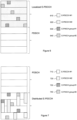
- Figure 1 illustrates a typical DL LTE subframe 110.
- Control information such as the PHICH (physical HARQ (hybrid automatic repeat request) indicator channel), PCFICH (physical control format indicator channel), and PDCCH are transmitted in a control channel region 120.
- the PHICH is used to transmit HARQ acknowledgements and negative acknowledgements (ACK/NACK), which may indicate whether the eNB has correctly received uplink scheduled data on the physical uplink shared channel (PUSCH).
- HARQ hybrid automatic repeat request
- PCFICH physical control format indicator channel
- PDCCH Physical Downlink shared channel
- the control channel region 120 includes the first few OFDM (orthogonal frequency division multiplexing) symbols in the subframe 110.
- the exact number of OFDM symbols for the control channel region 120 may be dynamically indicated by a control format indicator (CFI) in the PCFICH, which is transmitted in the first symbol.
- CFI control format indicator
- the number of OFDM symbols may be semi-statically configured when cross carrier scheduling is configured in the case of carrier aggregation in LTE Rel-10.
- the PDSCH, PBCH (physical broadcast channel), PSC/SSC (primary synchronization channel/secondary synchronization channel), and CSI-RS (channel state information reference signal) are transmitted in a PDSCH region 130.
- DL user data is carried by the PDSCH channels scheduled in the PDSCH region 130.
- Cell-specific reference signals are transmitted over both the control channel region 120 and the PDSCH region 130, as described in more detail below.
- Each subframe 110 can include a number of OFDM symbols in the time domain and a number of subcarriers in the frequency domain.
- An OFDM symbol in time and a subcarrier in frequency together define a resource element (RE).
- a physical resource block (physical RB or PRB) can be defined as, for example, 12 consecutive subcarriers in the frequency domain and all the OFDM symbols in a slot in the time domain.
- An RB or PRB pair with the same RB index in slot 0 (140a) and slot 1 (140b) in a subframe can be allocated together.
- Figure 2 shows an LTE DL resource grid 210 within each slot 140 in the case of a normal cyclic prefix (CP) configuration.
- the resource grid 210 is defined for each antenna port, i.e., each antenna port has its own separate resource grid 210.
- Each element in the resource grid 210 for an antenna port is an RE 220, which is uniquely identified by an index pair of a subcarrier and an OFDM symbol in a slot 140.
- An RB 230 includes a number of consecutive subcarriers in the frequency domain and a number of consecutive OFDM symbols in the time domain, as shown in the figure.
- An RB 230 is the minimum unit used for the mapping of certain physical channels to REs 220.
- CRSs cell-specific reference signals
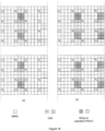
- Figure 3 shows an example of CRS locations in a subframe for two antenna ports 310a and 310b, where the RE locations marked with "R0" and “R1” are used for CRS port 0 and CRS port 1 transmission, respectively.
- REs marked with "X” indicate that nothing should be transmitted on those REs, as CRSs will be transmitted on the other antenna.
- REGs Resource element groups
- a REG includes either four or six consecutive REs in an OFDM symbol, depending on whether the CRSs are included.
- the REG allocation in each RB is shown in Figure 4 , where the control region 410 includes two OFDM symbols and different REGs are indicated with different types of shading.
- REs marked with "R0" or "X” in Figure 4a or with "R1” or “X” in Figure 4b are reserved for CRSs for antenna port 0 and antenna port 1, and therefore only four REs in each REG are available for carrying control channel data.
- a PDCCH can be transmitted on an aggregation of one or more consecutive control channel elements (CCEs), where one CCE consists of, for example, nine REGs.
- CCEs control channel elements
- the CCEs available for a UE's PDCCH transmission are numbered from 0 to n CCE -1.
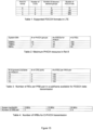
- multiple formats are supported for the PDCCH as shown in Table 1 in Figure 15 .
- the number of CCEs available in a subframe depends on the system bandwidth and the number of OFDM symbols configured for the control region. For example, in a 10 MHz system with three OFDM symbols configured for the control region and six groups configured for the PHICH, 42 CCEs are available for the PDCCH.
- Multiple PDCCHs may be multiplexed in the control region in a subframe to support UL and DL data scheduling for one UE and to support DL and UL scheduling for more than one UE.
- the number of PDCCHs that can be supported in the control region also depends on the aggregation level used for each PDCCH.
- the aggregation level indicates how many CCEs are aggregated to carry a PDCCH.
- the aggregation level for a given target packet error rate is determined by the downlink received signal quality at a UE and the size of the downlink control information (DCI) to be carried by a PDCCH.
- DCI downlink control information
- a high aggregation level is needed for a PDCCH intended for a UE that is at the cell edge and is far away from the serving eNB, or when a DCI with a large payload size is used.
- the legacy PDCCH region in LTE may have capacity issues for some new applications or deployment scenarios where the number of scheduled UEs in a subframe could be large.
- Some examples include multiple user multiple input multiple output (MU-MIMO) transmission, coordinated multi-point (CoMP) transmission, heterogeneous network (hetnet) deployment with remote radio heads (RRHs) in a cell sharing the same cell ID, and carrier aggregation (CA).
- MU-MIMO multiple user multiple input multiple output
- CoMP coordinated multi-point
- Hetnet heterogeneous network deployment with remote radio heads (RRHs) in a cell sharing the same cell ID
- CA carrier aggregation
- E-PDCCH extended or enhanced PDCCH
- a set of RBs and OFDM symbols or PRB pairs reserved for this purpose can be referred to as an E-PDCCH region.
- the E-PDCCH region in a subframe is not necessarily completely filled with E-PDCCHs in that some resources in the E-PDCCH region not used for E-PDCCH transmission can be assigned for PDSCH transmission.
- the legacy PDCCH region may or may not be present in a subframe containing an E-PDCCH region.
- the time and frequency resources of an E-PDCCH region may be configurable. Examples of E-PDCCH regions are shown in Figure 5 .
- Multiple PHICHs may be transmitted in the same set of resource elements and may be defined as a PHICH group.
- multiple PHICHs may be multiplexed with different complex orthogonal Walsh sequences.
- eight PHICHs can be multiplexed within a PHICH group, as the length of the orthogonal sequence is four and the PHICHs are also multiplexed over the I and Q branches.
- four PHICHs can be multiplexed within a PHICH group with length-2 Walsh sequences.
- the PHICH duration and the number of PHICH groups are signaled in the master information block (MIB): the PHICH duration and the number of PHICH groups.
- the duration of the PHICH specifies the number of OFDM symbols that the PHICH is distributed over. To avoid dependency with the PCFICH, the duration is independently signaled and can be different from the control region for the PDCCH.
- the second parameter is used to define the amount of PHICH resources, i.e., the number of PHICH groups.
- the mapping between PHICH resources and the corresponding uplink scheduled transmission is implicit. That is, there is a predefined mapping rule between the PHICH resource index and the PUSCH PRB index transmitting the uplink shared channel.
- the PHICH resource is mapped to the actual PUSCH PRB index instead of the PDCCH CCE index.
- a PHICH resource is identified by the index pair ( n PHICH group , n PHICH seq ) where n PHICH group is the PHICH group number and n PHICH seq is the orthogonal sequence index within the group.
- n PHICH group is the PHICH group number
- n PHICH seq is the orthogonal sequence index within the group.
- the UE derives the assigned index pair with the scheduled PUSCH PRB index. If the PHICH resource is smaller than the number of PUSCH PRBs or if multiple users are scheduled in the same PUSCH PRBs, a collision can happen. That is, the same PHICH resource may be assigned to multiple UEs.
- a different cyclic shift value which is indicated in the uplink DCI format, may be used to derive the assigned PHICH resource. More specifically, the following equation may be used to determine the index pair.
- n PHICH group I PRB _ RA lowest _ index + n DMRS modN PHICH group + I PHICH N PHICH group
- n PHICH seq I PRB _ RA lowest _ index / N PHICH group + n DMRS mod 2 N SF PHICH
- n DMRS is mapped from the cyclic shift for the demodulation reference signal (DMRS) field in the most recent DCI format 0 or 4 for the transport block associated with the corresponding PUSCH transmission.
- n DMRS is set to zero if there is no PDCCH with DCI format 0 or 4 for the same transport block and if the initial PUSCH for the same transport block is semi-persistently scheduled or the initial PUSCH for the same transport block is scheduled by the random access response grant.
- N SF PHICH is the spreading factor size used for PHICH modulation as described in section 6.9.1 of 3GPP Technical Specification (TS) 36.213.
- I PRB _ RA lowest _ index is the lowest PRB index in the first slot of the corresponding PUSCH transmission.
- N PHICH group is the number of PHICH groups configured by higher layers as described in section 6.9 of 3GPP TS 36.213.
- the E-PDCCH specified in LTE Rel-11 systems may support increased control channel capacity, may support frequency domain inter-cell interference coordination (ICIC), may achieve improved spatial reuse of control channel resources, may support beamforming and/or diversity, may operate on advanced carrier types and in MBSFN subframes, and may coexist on the same carrier with legacy UEs.
- the E-PDCCH may be transmitted by using PDSCH resources, so the introduction of the E-PDCCH may have no impact on legacy PDCCH transmissions. Further, the E-PDCCH may increase control channel capacity by borrowing PDSCH resources.
- the E-PDCCH may be transmitted within downlink PRBs or PRB pairs instead of being spread over the entire system bandwidth.
- the time domain if the E-PDCCH is distributed over the subframe in the PDSCH region, additional signaling may not be necessary. Otherwise, the number of OFDM symbols may need to be signaled.
- the E-PDCCH region in the frequency domain and time domain may be signaled with radio resource control (RRC) signaling or dynamic signaling.
- RRC radio resource control
- the E-PDCCH region may be multiplexed with the PDSCH only in the frequency domain. Therefore, E-PDCCHs may be transmitted in different PRBs or PRB pairs from the PRB pairs on which PDSCHs are transmitted. Alternatively, the E-PDCCH and the PDSCH may be transmitted in the same PRB or PRB pair by dividing the number of OFDM symbols in the time domain.
- Both localized and distributed transmission may be supported for the E-PDCCH.
- the demodulation of the enhanced control channel may be based on the DMRS transmitted in the PRBs or PRB pairs used for transmission of the E-PDCCH.
- the number of PHICHs is dependent on the number of PRBs, the number of orthogonal sequences, and the parameter N g where N g ⁇ ⁇ 1/6,1/2,1,2 ⁇ is provided by higher layers. For example, in case of 20 MHz and the normal cyclic shift, the maximum number of PHICHs is 200 if N g is configured as 2. Meanwhile, in the case of the PDCCH, the maximum number of PDCCHs is 88, assuming that the PDCCH aggregation level is 1 and that three OFDM symbol are used for the control region.
- the maximum number of PHICH resources is approximately double of the number of PRBs in the same system bandwidth.
- the number of PHICH resources is larger than the PDCCH resource capacity, increasing the PHICH capacity may be important in some scenarios. For example, when an additional carrier without a control region is supported or when a control channel experiences strong interference, the PHICH for the additional carrier may need to be transmitted on the primary carrier.
- Another example is the scenario where remote radio heads (RRHs) with the same cell ID as the macro eNB are supported. In this case, the number of UEs scheduled to transmit the PUSCH may be dramatically increased.
- the current PHICH structure may not be efficient for frequency domain ICIC because the PHICH is distributed over the entire system bandwidth.
- Embodiments of the present disclosure provide a detailed design for an extended or enhanced PHICH (E-PHICH) structure, including resource allocation and multiplexing between the E-PHICH and the E-PDCCH. More specifically, at least four issues related to the E-PHICH are identified, and at least one set of embodiments is disclosed for each of the issues. The embodiments will be briefly summarized, and then details will be provided for each set of embodiments.
- E-PHICH extended or enhanced PHICH
- the first set of embodiments deals with multiplexing of the E-PHICH with the E-PDCCH or the PDSCH.
- E-PHICHs may be transmitted with localized E-PDCCH transmission in the same PRBs or PRB pairs as the PRBs used for the E-PDCCHs.
- E-PHICHs may be transmitted in PRBs or PRB pairs for E-PDCCHs configured with distributed transmission.
- E-PHICHs may be transmitted in PRBs or PRB pairs where commonly monitored E-PDCCHs are transmitted.
- a common search space may be defined for E-PDCCHs to transmit DCI formats aimed to all UEs or group of UEs.
- E-PHICHs may be multiplexed with E-PDCCHs in the PRBs or PRB pairs reserved for the common search space.
- E-PHICHs may be transmitted in PRBs or PRB pairs for PDSCH transmission.
- An E-PHICH may be transmitted in a different PRB or PRB pair from an E-PDCCH.
- the E-PHICH may be multiplexed with the PDSCH in the same PRBs or PRB pairs.
- an E-PHICH may be transmitted alone in separate virtual resource blocks (VRBs). Different E-PHICH groups may be multiplexed and interleaved before mapping across VRBs. The VRBs may then be mapped to PRBs in a distributed manner. Frequency hopping may be applied to the second slot of the VRBs.
- VRBs virtual resource blocks
- the second set of embodiments deals with resource allocation for the E-PHICH.
- Multiple PHICH resource sets may be defined to efficiently utilize E-PHICH resources.
- Each PHICH resource set can be mapped to a PUSCH PRB index.
- the actually used E-PHICH resource set may be explicitly indicated with semi-static signaling or dynamic signaling. Alternatively, the actually used E-PHICH resource may be implicitly indicated with a CCE index of the E-PDCCH or PDCCH transmitting the uplink grant.
- the third set of embodiments deals with monitoring and receiving the PHICH and the E-PHICH.
- the UE may monitor and receive both the PHICH and the E-PHICH.
- the actual PHICH or E-PHICH resource may be determined depending on the PUSCH PRB index and the DMRS cyclic shift, where the number of E-PHICHs that are supported could be signaled or re-interpreted from the PBCH or signaled through higher layer signaling.
- the UE may receive the E-PHICH only if the UE is configured to monitor the E-PDCCH region or if the eNB configures the UE to receive the E-PHICH only.
- the fourth set of embodiments deals with inter-cell interference management for the E-PHICH.
- inter-cell interference coordination may be supported for E-PHICH transmissions.
- a signal related to a PHICH resource may be exchanged between cells, and the E-PHICH resource parameter may be signaled to the connected UEs.
- the detailed E-PHICH procedure may depend on whether the legacy control region is supported or not.
- E-PHICHs are transmitted in VRBs for E-PDCCHs configured with localized transmission.
- an E-PDCCH is transmitted in either one or multiple consecutive VRBs that are not used for transmission of other E-PDCCHs. Since one E-PDCCH is transmitted within one or multiple PRBs (or PRB pairs) and precoded DMRS is used, interleaving between multiple E-PDCCHs as used in the legacy PDCCH may not be supported in localized E-PDCCH transmissions.
- the VRBs may be mapped to PRBs, which may be either consecutive or non-consecutive in frequency.
- FIG. 6 shows one example of multiplexing the E-PHICH and the E-PDCCH with localized transmission.
- Two E-PDCCHs 610 and 620 that are transmitted in separate PRB pairs are illustrated.
- Two E-PHICH groups 630 and 640 are shown, each of which contains multiple units (as the PHICH is repeated three times as defined in Rel-8), and these units are spread across the whole E-PDCCH region.
- the precoded DMRS may not be suitable for decoding the E-PHICH because the E-PHICH may contain ACK/NACKs for multiple UEs.
- a common reference signal such as the CRS or a transmission point (TP)-specific reference signal that is not precoded
- TP transmission point
- a precoded DMRS may still be used to decode the E-PHICH because the precoding vectors used in each PRB pair may not be the same, thus creating some spatial diversity in addition to frequency/time diversity.
- E-PHICH transmission may be multiplexed in a similar way as it is multiplexed with an E-PDCCH with a localized E-PDCCH transmission.
- E-PHICHs are transmitted in VRBs for E-PDCCHs configured with distributed transmission.
- E-PDCCHs For an E-PDCCH with distributed transmission, multiple E-PDCCHs may be multiplexed and interleaved together and transmitted on the same VRBs.
- a distributed transmission may be more suitable than a localized transmission for the E-PHICH to achieve more frequency diversity instead of frequency selectivity.
- the E-PHICH may be multiplexed with the E-PDCCH and may be configured only with distributed transmission and use a non-precoded DMRS for decoding. As shown in Figure 7 , two E-PDCCHs 710 and 720 are multiplexed and transmitted on the same PRB pairs, and two E-PHICH groups 730 and 740 are transmitted from the same PRB pairs as the E-PDCCH.
- E-PDCCH resources are RRC configured, then the E-PHICH may be multiplexed together with the distributed E-PDCCH (cross-interleaved).
- Two regions may be configured for the E-PDCCH, one distributed and the other localized. Although two regions may be configured, it is possible that only the distributed E-PDCCH region contains E-PHICH resources.
- a UE may be configured to do E-PDCCH blind decoding in one or both regions (i.e., distributed only, localized only, or both). However, all UEs may need to decode the E-PHICH in a distributed E-PDCCH region if a HARQ-ACK is expected, because the E-PHICH may be transmitted only in the distributed E-PDCCH region in this case.
- some resources may be configured for the E-PHICH.
- REGs could be defined over the VRBs, and some REGs may be for the E-PHICH only.
- E-PHICH groups may be similarly defined as in the legacy PHICH. The rest of the REGs may then be grouped into CCEs and used for the E-PDCCH.
- a reference signal for demodulation may be shared in the region. Either a CRS or a non-precoded DMRS may be used.
- the number of DMRS ports may be the same as the number of CRS ports as indicated by decoding the PBCH. Alternatively, the number of DMRS ports may be different from the number of CRS ports and may be configured by RRC signaling. Different DMRS ports or sequence may be configured and used in different cells.
- the REG definition in OFDM symbols with a DMRS and/or a CSI-RS may need to be modified, as the REs in an OFDM symbol may not be an even number or multiples of four REs.
- One alternative for REG definition in those OFDM symbols may be to define a REG as a 2REx2RE square unit that occupies two consecutive REs in the frequency domain and two consecutive REs in the time domain.
- a REG could be divided into two pairs of REs, each consisting of two consecutive REs in the frequency domain. These two pairs of REs could be consecutively allocated along frequency, but in the case where there are not enough REs left in an OFDM symbol, the second pair could start from the next OFDM symbol.
- the allocation of REs for an E-PHICH REG may skip those REs reserved for DMRS or CSI-RS transmission. If there is only one orphan RE left in an OFDM symbol, the RE may be skipped.
- Transmit diversity may be used, and random beamforming may also be possible, either on a per-RB or a per-REG basis, but precoding vectors may need to be predefined in case of per-REG beamforming.
- E-PHICHs are transmitted in VRBs for E-PDCCHs that are commonly monitored. That is, it may be possible to multiplex an E-PHICH with an E-PDCCH monitored by all UEs or group of UEs, for instance in a common search space.
- the E-PHICH may be transmitted in the same VRBs configured as the common search space for the E-PDCCH as shown in Figure 8 .
- the resources used to transmit the E-PHICH may be pre-defined and known to the UE.
- the resources may be interleaved with the E-PDCCHs that carry the common message.
- the UE may only need to decode the E-PHICH when the UE expects ACK/NACK signals.
- transmit diversity may be used and/or a non-precoded DMRS may be used as a reference signal.
- E-PHICHs are transmitted in PRB pairs for PDSCH transmission.
- E-PHICH resources may be within the resources used for the PDSCH. That is, the E-PHICH may be multiplexed with the PDSCH in the same PRB pairs.
- the PRBs used for the E-PHICH may be defined similarly to the way the E-PDCCH regions are defined. For example, the number and location of E-PHICH RBs may be signaled to advanced UEs or may be predefined.
- the maximum number of resource elements required for the legacy PHICH is calculated in Table 2 in Figure 15 with respect to the system bandwidth.
- Table 3 in Figure 15 shows available resource elements in a PRB pair in a subframe for PDSCH data transmission for different control region configurations and four CRS ports. Assuming the same or a similar amount of PHICH resources may need to be supported in the E-PHICH, then a maximum of three PRB pairs may be needed for 20 MHz, and less than one PRB pair may be needed for 5 MHz or less.
- the granularity for E-PHICH resources may be coarse if only the E-PHICH is transmitted in a PRB pair.
- the E-PHICH may be mapped to REs that are otherwise used for PDSCH transmission, as illustrated in Figure 9 .
- the manner in which the E-PHICHs are mapped in the PDSCH may be pre-defined or configured through higher signaling.
- the E-PHICH may take resources in units of REG in a similar way as the legacy PHICH does in the PDCCH region.
- the unit REG may be composed of, e.g., four closely located REs. Since the E-PHICH may be spread out and may not be required to take as many REs within a PRB pair as possible, higher-order diversity may be achieved, which may lead to better performance of the PHICH.
- the PDSCH there are at least two options for the PDSCH in terms of how to take into account the REs that are reserved for E-PHICHs. If the PDSCHs are used for legacy UEs, puncturing of the PDSCHs at the RE locations configured for E-PHICHs may be used to ensure that legacy UEs can still receive the PDSCH. If the PDSCHs are used for advanced UEs only, then rate matching may be applied to take into account the REs reserved for E-PHICHs.
- the reference signal used for decoding may need to be a common reference signal, such as a cell-specific reference signal or a TP-specific reference signal. Such a reference signal may be different from the reference signal for PDSCH decoding, which could be precoded.
- E-PHICHs are transmitted in their own VRBs. That is, an E-PHICH may be transmitted in a VRB that is used only to carry HARQ ACK/NACK signals.
- the required number of REs for the E-PHICH is in the range of REs that can be carried by one to three PRB or VRB pairs. So one to three PRBs in both slots could be assigned to transmit the E-PHICH only in the legacy PDSCH region.
- Table 4 in Figure 15 shows the possible number of VRB pairs that may be used to carry an E-PHICH-only transmission for different system bandwidths.
- each E-PHICH consists of three REGs, which represent its three repetitions.
- REGs carrying one E-PHICH group are multiplexed and interleaved with REGs of other E-PHICH groups and mapped across assigned VRBs in both slots that only carry an E-PHICH. These VRBs in both slots may then be mapped to PRBs in distributed manners across the whole system bandwidth, thus creating more frequency diversity gain.
- hopping operation may be applied to the VRB in the second slot (i.e., a VRB of the distributed type), so that the VRBs are transmitted at different frequencies in the first and second slots.
- the VRB configuration parameters e.g., distributed vs localized, gap 1 vs gap 2
- the E-PHICH and the common search space of the E-PDCCH such parameters may be signaled once for all relevant enhanced downlink control channels.
- REGs of different E-PHICH groups may be lined up according to their E-PHICH group number.
- a REG-based interleaver such as a row-in/column-out block interleaver, may be applied, whose output is REGs from different E-PHICH groups in mixed order.
- 2-tx and 4-tx transmit diversity (TxD) based on Alamouti coding may be applied to an E-PHICH transmission.
- the configuration of antenna number for TxD may be signaled to the UE or may be implied by another configuration, such as that for distributed E-PDCCH transmission.
- a CRS may be used for decoding the E-PHICH in such a transmission.
- a DMRS without channel dependent precoding may be used for this purpose. If hopping is applied to the second slot (i.e., DVRB), the DMRS may need to be re-designed to ensure that the performance of the E-PHICH is maintained, especially in high mobility situations.
- the location of such PRB pairs for E-PHICH-only transmission may vary for different cells or TPs to avoid collisions of E-PHICHs from different cells and TPs.
- One way to implement this variance is to link the locations of PRB pairs for the E-PHICH to the cell ID or an additional or alternative parameter distinct to each TP.
- the configuration of an E-PHICH-only transmission may be semi-statically signaled to the UE through higher layer signaling, such as RRC signaling.
- the configuration may include parameters such as the number of VRB used, the VRB-to-PRB mapping, the location where the second slot is hopped to, the transmit mode (e.g., TxD), the number of transmit antennas, and the corresponding reference signal ports for decoding.
- a second set of embodiments deals with resource allocation for the E-PHICH.
- one PHICH resource set is defined in a cell, and a PHICH resource (i.e., an index pair of a PHICH group and orthogonal sequence index in the group) is implicitly mapped to the starting index of the PRBs of a scheduled PUSCH.
- multiple PHICH/E-PHICH resource sets are provided to increase PHICH capacity, while efficiently utilizing E-PHICH resources.
- An E-PHICH resource set is a collection of E-PHICH resources, where each E-PHICH resource is capable of carrying one E-PHICH that corresponds to a previous PUSCH transmission. The individual resource in the resource set is specified by a resource index.
- a resource index is the index pair ( n PHICH group , n PHICH seq ) where n PHICH group is the PHICH group number and n PHICH seq is the orthogonal sequence index within the group.
- E-PHICH resources within a set can be mapped to all PUSCH PRB indices.
- Figure 13 shows E-PHICH resources mapping to PUSCH PRBs logically. In this figure, it is assumed that the number of PHICHs in an E-PHICH resource set is equal to the number of PUSCH PRBs.
- E-PHICH resource set #1 and set #2 If the number of PHICHs in an E-PHICH resource set is smaller than the number of PUSCH PRBs, different DMRS cyclic shifts may be signaled to different PUSCHs in order to avoid collisions in the actual PHICH transmissions. As shown in Figure 13 , for one PUSCH PRB, two E-PHICHs can be mapped in E-PHICH resource set #1 and set #2.
- Collisions between E-PHICH resources assigned to multiple UEs can happen when the number of E-PHICH resources is smaller than the number of PUSCH PRBs or when multiple UEs are allocated with the same PUSCH PRB, in the case of multiple-user multiple input/multiple output (MU-MIMO) for example. In such a case, different cyclic shifts may be signaled to avoid collision.
- MU-MIMO multiple-user multiple input/multiple output
- E-PHICH PRB resource sets may be useful in the scenario where multiple E-PHICHs are multiplexed with different types of E-PDCCH regions.
- E-PHICH resource set 1 may be multiplexed with an E-PDCCH configured with localized transmission
- E-PHICH resource set 2 may be multiplexed with an E-PDCCH configured with distributed transmission.
- the UE may need to monitor and receive the E-PHICH in E-PHICH resource set 1 only when a PUSCH PRB is scheduled by an E-PDCCH localized transmission.
- the UE may need to monitor and receive the E-PHICH in E-PHICH resource set 2 only when a PUSCH PRB is scheduled by an E-PDCCH distributed transmission. This may reduce UE complexity by not receiving the E-PHICH over all E-PHICH resources.
- E-PHICH PRB resource sets may also be useful in the scenario where multiple reference signal structures or transmission schemes may be required. For example, when multiple RRHs are configured with the same cell ID and E-PHICHs are transmitted in different RRHs with different reference signals, it may be desirable to receive the E-PHICH from an RRH suitable for the UE. In this case, a separate E-PHICH resource set may be configured for each RRH.
- E-PHICH PRB resource sets may also be useful in the scenario where saving the resources reserved for the E-PHICH may be required.
- an E-PHICH resource may be mapped to a PUSCH PRB index, the same amount of E-PHICH resources as the number of PUSCH PRBs may not be required because multiple PRBs can be scheduled to one UE.
- the amount of PHICH resources is configured with the PBCH, and hence may be difficult to change, depending on the number of actually required PHICH resources.
- the E-PHICH resource set is dynamically indicated in the uplink grant, it may be possible to reduce the resources reserved for the E-PHICH by assigning the E-PHICH to a certain E-PHICH group only. Therefore, depending on the number of UEs scheduled for PUSCH transmission, all E-PHICH transmissions may be limited to one E-PHICH resource set, and the remaining E-PHICH resource sets may be used for PDSCH transmissions.
- E-PHICH resource sets may be assigned in different frequency, time or code sequence domains.
- two E-PHICH resource sets are configured, and the E-PHICH in each set is mapped to a PUSCH PRB.
- E-PHICH resources It is not necessarily required to reserve twice the amount of the E-PHICH resources and map the resources to PUSCH PRBs in each E-PHICH resource set, because multiple PUSCH PRBs may be allocated to one UE and only one or two PHICH resources may be required to transmit one or two HARQ ACKs.
- the actually used E-PHICH resource set may be either semi-statically configured or dynamically indicated by including E-PHICH resource set information explicitly in an uplink grant. For example, if the maximum four E-PHICH resource sets are supported, two bits of information may be included to indicate which E-PHICH resource set is used. Alternatively, implicit indication is also possible, where the CCE or eCCE index of the E-PDCCH carrying the uplink grant may be used to derive the E-PHICH resource set.
- ⁇ S 0 , S 1 ,...,S M -1 ⁇ be the M sets of E-PHICH resources and n be the lowest CCE or eCCE index of an E-PDCCH carrying an uplink grant for PUSCH transmission.
- N PHICH group may be the number of PHICH groups in the corresponding E-PHICH resource set.
- a third set of embodiments deals with monitoring and receiving the PHICH and the E-PHICH. If both legacy control regions and the E-PHICH are supported and configured, an advanced UE may monitor and receive both the PHICH and the E-PHICH. If an advanced UE is configured to receive both the PDCCH and the E-PDCCH, the UE may also be able to receive both the PHICH and the E-PHICH. In this case, all PHICH and E-PHICH resources may be jointly mapped to a PUSCH PRB index. For a UE receiving both the PHICH and the E-PHICH, the equation for deriving a PHICH resource may need to be modified.
- n PHICH group I PRB _ RA lowest _ index + n DMRS mod N PHICH group + N E ⁇ PHICH group + I PHICH N PHICH group + N E ⁇ PHICH group
- n PHICH seq I PRB _ RA lowest _ index / N PHICH group + N E ⁇ PHICH group + n DMRS mod 2 N SF PHICH
- the UE may compare the calculated n PHICH group with N PHICH group . Specifically, the UE may know that the E-PHICH resource is used if n PHICH group is larger than or equal to N PHICH group .
- the number of groups for the PHICH N PHICH group
- the number for an E-PHICH group N E ⁇ PHICH group
- the number for an E-PHICH group may be signaled in the PBCH using unused bits.
- the number for an E-PHICH group may be signaled by higher layer signaling.
- a PHICH or E-PHCIH resource may be used depending on the PUSCH PRB index and whether a DMRS value meets certain criteria. For example,
- the PHICH may be used when an uplink DCI grant is transmitted on the PDCCH and that the E-PHICH may be used when an uplink DCI grant is transmitted on the E-PDCCH.
- the PHICH group index equation can be defined as follows.
- each RRH is configured with a TP-specific E-PDCCH region.
- the TP ID may be used to define such TP-specific features.
- a UE monitors only the E-PDCCH, complications may arise in enabling the UE to receive both the PHICH and the E-PHICH.
- the UE may not receive the PHICH correctly if interference is high in the legacy region. Therefore, the UE may receive the E-PHICH only when the UE is configured to monitor only the E-PDCCH.
- the eNB may perform configuration separately whether the UE receives the PHICH or not.
- the phich-config field carried in the MIB may be re-interpreted for E-PHICH resource configuration, as shown below.
- the E-PHICH may reside in the OFDM symbols carrying the DMRS and/or the REs close to the DMRS REs in the first slot only, as illustrated in Figure 14(a) .
- the E-PHICH may spread to the OFDM symbols carrying the DMRS and/or the REs close to the DMRS REs in the both the first and the second slot of a subframe, as illustrated in Figure 14(b) .
- the 'phich-Resource' field can be used for calculating the number of E-PHICH groups as for the PHICH, resulting in the same amount of resources allocated for the E-PHICH and the PHICH. If it is desired to allocate more resources to the E-PHICH than the PHICH, then the value of 'phich-Resource' can be re-interpreted for the E-PHICH. This can happen, for example, when a large number of UEs need to be served while the PHICH is not available (e.g., if there is no legacy control region).
- the number of groups in the E-PHICH may be twice that of the PHICH.
- the PBCH may still contain the information only for the PHICH.
- a UE may receive information about the PHICH from the PBCH and start to monitor and receive the PHICH first.
- the UE may be configured to monitor and receive the E-PHICH semi-statically through higher layer signaling. Such a configuration may be sent together or separately with the configuration of the E-PDCCH. After such a configuration is received, the UE may start to monitor and receive the E-PHICH.
- a fourth set of embodiments deals with inter-cell interference management for the E-PHICH.
- the inter-cell interference coordination (ICIC) mechanism may be leveraged to achieve interference avoidance between the E-PHICHs of neighbor cells in the frequency domain. That is, two neighbor cells may transmit E-PHICHs over non-overlapping PRBs. This implies that the E-PHICH resource is keyed off an ICIC parameter.
- a signal may be exchanged over the X2 interface between two neighbor cells, and the E-PHICH resource parameter may be signaled to the connected UEs via a system information block (SIB).
- SIB system information block
- the X2 signaling as defined in Rel-8 for ICIC may be reused to achieve this coordination after resources for E-PHICH transmission are allocated.
- the UE Before such a parameter is received by the UE, the UE may monitor the PHICH only.
- the X2 exchange may not be needed to coordinate two RRHs of the same eNB.
- the eNB scheduler may define such a PHICH resource parameter without any dependency on X2 signaling.
- the E-PHICH resource unit may be shifted based on cell ID, so that E-PHICHs from different cells do not collide. Such a shift could be REG-based or PRB-based.
- interference randomization in the design of the E-PHICH may still be needed for one or more reasons.
- the neighbor cells may not always choose to coordinate (e.g., two cells may belong to two different operators).
- One example of providing interference randomization is a case where the REG resources for the E-PHICH vary as a function of the subframe number as well as the cell ID so that two cells would be likely to use different REGs in a given subframe.
- a component carrier has a legacy control region on the downlink, and the associated uplink CC may or may not be cross-carrier scheduled.
- the UE may receive a downlink ACK/NACK via the PHICH only in the legacy control region, when the UE attaches initially.
- the network directs the UE to receive an ACK/NACK via the E-PHICH only via UE-specific RRC signaling, the UE may switch to receive the E-PHICH only for all future subframes until further notice.
- the UE-specific RRC signaling may carry resource allocation information for the E-PHICH so that the UE can locate the E-PHICH directly for future subframes.
- Information carried on the UE-specific RRC signaling may include the PRB location of the E-PHICH, which takes into account the interference coordination between two neighboring cells or two neighboring RRHs.
- the same UE-specific RRC signaling may also trigger the UE to receive a downlink control channel via the E-PDCCH.
- the network directs the UE to stop detecting the E-PHICH, then the UE may switch to receive the PHICH only for all future subframes until further notice.
- a component carrier, CC B that has no legacy control region on the downlink is associated with another component carrier, CC A , that has a legacy control region.
- the UE may receive a downlink ACK/NACK via the PHICH only in the legacy control region of CC A , when the UE attaches initially.
- the network adds CC B to the UE as a secondary cell (SCell)
- the UE may start to receive all downlink control signals only on CC B . This implies that the UE switches to receive the E-PHICH (and E-PDCCH) only on CC B for all future subframes until further notice.
- the eNB may need to configure the E-PHICH (and E-PDCCH) on CC B before CC B is added as an SCell, as CC B may experience less interference from other cells or TPs.
- the network removes CC B from the UE's SCell list, the UE may switch to receive downlink control channels only on CC A for all future subframes until further notice.
- the embodiments disclosed herein provide a detailed multiplexing scheme for the E-PHICH and the E-PDCCH and/or PDSCH.
- the E-PHICH may be transmitted alone in some PRBs. Consequently, the embodiments can achieve efficient resource utilization for the E-PHICH given the characteristic of the E-PDCCH and/or PDSCH.
- the embodiments also provide efficient utilization of PHICH resources by using a concept of multiple PHICH resource sets.
- the embodiments further enable a UE to receive HARQ-ACK when both the PHICH and the E-PHICH are supported in an LTE eNB.
- the embodiments provide ICIC management for the E-PHICH that can avoid interference on the E-PHICH.
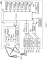
- network element 3110 includes a processor 3120 and a communications subsystem 3130, where the processor 3120 and communications subsystem 3130 cooperate to perform the methods described above.
- UE 3200 may comprise a two-way wireless communication device having voice and data communication capabilities. In some embodiments, voice communication capabilities are optional.
- the UE 3200 generally has the capability to communicate with other computer systems on the Internet.
- the UE 3200 may be referred to as a data messaging device, a two-way pager, a wireless e-mail device, a cellular telephone with data messaging capabilities, a wireless Internet appliance, a wireless device, a smart phone, a mobile device, or a data communication device, as examples.
- the UE 3200 may incorporate a communication subsystem 3211, including a receiver 3212 and a transmitter 3214, as well as associated components such as one or more antenna elements 3216 and 3218, local oscillators (LOs) 3213, and a processing module such as a digital signal processor (DSP) 3220.
- a communication subsystem 3211 including a receiver 3212 and a transmitter 3214, as well as associated components such as one or more antenna elements 3216 and 3218, local oscillators (LOs) 3213, and a processing module such as a digital signal processor (DSP) 3220.
- the particular design of the communication subsystem 3211 may be dependent upon the communication network in which the UE 3200 is intended to operate.
- Network access requirements may also vary depending upon the type of network 3219.
- network access is associated with a subscriber or user of the UE 3200.
- the UE 3200 may require a removable user identity module (RUIM) or a subscriber identity module (SIM) card in order to operate on a network.
- RUIM removable user identity module
- SIM subscriber identity module
- the SIM/RUIM interface 3244 is typically similar to a card slot into which a SIM/RUIM card may be inserted.
- the SIM/RUIM card may have memory and may hold many key configurations 3251 and other information 3253, such as identification and subscriber-related information.
- the UE 3200 may send and receive communication signals over the network 3219.
- the network 3219 may consist of multiple base stations communicating with the UE 3200.
- Signals received by antenna 3216 through communication network 3219 are input to receiver 3212, which may perform such common receiver functions as signal amplification, frequency down conversion, filtering, channel selection, and the like.
- Analog to digital (A/D) conversion of a received signal allows more complex communication functions, such as demodulation and decoding to be performed in the DSP 3220.
- signals to be transmitted are processed, including modulation and encoding for example, by DSP 3220 and are input to transmitter 3214 for digital to analog (D/A) conversion, frequency up conversion, filtering, amplification, and transmission over the communication network 3219 via antenna 3218.
- DSP 3220 not only processes communication signals but also provides for receiver and transmitter control. For example, the gains applied to communication signals in receiver 3212 and transmitter 3214 may be adaptively controlled through automatic gain control algorithms implemented in DSP 3220.
- the UE 3200 generally includes a processor 3238 which controls the overall operation of the device. Communication functions, including data and voice communications, are performed through communication subsystem 3211. Processor 3238 also interacts with further device subsystems such as the display 3222, flash memory 3224, random access memory (RAM) 3226, auxiliary input/output (I/O) subsystems 3228, serial port 3230, one or more keyboards or keypads 3232, speaker 3234, microphone 3236, other communication subsystem 3240 such as a short-range communications subsystem, and any other device subsystems generally designated as 3242. Serial port 3230 may include a USB port or other port currently known or developed in the future.
- Some of the illustrated subsystems perform communication-related functions, whereas other subsystems may provide "resident" or on-device functions.
- some subsystems such as keyboard 3232 and display 3222, for example, may be used for both communication-related functions, such as entering a text message for transmission over a communication network, and device-resident functions, such as a calculator or task list.
- Operating system software used by the processor 3238 may be stored in a persistent store such as flash memory 3224, which may instead be a read-only memory (ROM) or similar storage element (not shown).
- ROM read-only memory
- the operating system, specific device applications, or parts thereof, may be temporarily loaded into a volatile memory such as RAM 3226. Received communication signals may also be stored in RAM 3226.
- flash memory 3224 may be segregated into different areas for both computer programs 3258 and program data storage 3250, 3252, 3254 and 3256. These different storage types indicate that each program may allocate a portion of flash memory 3224 for their own data storage requirements.
- Processor 3238 in addition to its operating system functions, may enable execution of software applications on the UE 3200.
- a predetermined set of applications that control basic operations, including at least data and voice communication applications for example, may typically be installed on the UE 3200 during manufacturing. Other applications may be installed subsequently or dynamically.
- the computer-readable storage medium may be tangible or in a transitory/non-transitory medium such as optical (e.g., CD, DVD, etc.), magnetic (e.g., tape), or other memory currently known or developed in the future.
- optical e.g., CD, DVD, etc.
- magnetic e.g., tape
- other memory currently known or developed in the future.
- One software application may be a personal information manager (PIM) application having the ability to organize and manage data items relating to the user of the UE 3200 such as, but not limited to, e-mail, calendar events, voice mails, appointments, and task items.
- PIM personal information manager
- One or more memory stores may be available on the UE 3200 to facilitate storage of PIM data items.
- Such a PIM application may have the ability to send and receive data items via the wireless network 3219.
- Further applications may also be loaded onto the UE 3200 through the network 3219, an auxiliary I/O subsystem 3228, serial port 3230, short-range communications subsystem 3240, or any other suitable subsystem 3242, and installed by a user in the RAM 3226 or a non-volatile store (not shown) for execution by the processor 3238.
- Such flexibility in application installation may increase the functionality of the UE 3200 and may provide enhanced on-device functions, communication-related functions, or both.
- secure communication applications may enable electronic commerce functions and other such financial transactions
- a received signal such as a text message or web page download may be processed by the communication subsystem 3211 and input to the processor 3238, which may further process the received signal for output to the display 3222, or alternatively to an auxiliary I/O device 3228.
- a user of the UE 3200 may also compose data items, such as email messages for example, using the keyboard 3232, which may be a complete alphanumeric keyboard or telephone-type keypad, among others, in conjunction with the display 3222 and possibly an auxiliary I/O device 3228. Such composed items may then be transmitted over a communication network through the communication subsystem 3211.
- UE 3200 For voice communications, overall operation of the UE 3200 is similar, except that received signals may typically be output to a speaker 3234 and signals for transmission may be generated by a microphone 3236.
- Alternative voice or audio I/O subsystems such as a voice message recording subsystem, may also be implemented on the UE 3200.
- voice or audio signal output may be accomplished primarily through the speaker 3234, display 3222 may also be used to provide an indication of the identity of a calling party, the duration of a voice call, or other voice call-related information, for example.
- Serial port 3230 may be implemented in a personal digital assistant (PDA)-type device for which synchronization with a user's desktop computer (not shown) may be desirable, but such a port is an optional device component.
- PDA personal digital assistant
- Such a port 3230 may enable a user to set preferences through an external device or software application and may extend the capabilities of the UE 3200 by providing for information or software downloads to the UE 3200 other than through a wireless communication network.
- the alternate download path may, for example, be used to load an encryption key onto the UE 3200 through a direct and thus reliable and trusted connection to thereby enable secure device communication.
- Serial port 3230 may further be used to connect the device to a computer to act as a modem.
- Other communications subsystems 3240 are further optional components which may provide for communication between the UE 3200 and different systems or devices, which need not necessarily be similar devices.
- the subsystem 3240 may include an infrared device and associated circuits and components or a Bluetooth TM communication module to provide for communication with similarly enabled systems and devices.
- Subsystem 3240 may further include non-cellular communications such as WiFi, WiMAX, near field communication (NFC), and/or radio frequency identification (RFID).
- RFID radio frequency identification
- the other communications element 3240 may also be used to communicate with auxiliary devices such as tablet displays, keyboards or projectors.
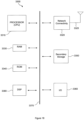
- FIG. 18 illustrates an example of a system 3300 that includes a processing component 3310 suitable for implementing one or more embodiments disclosed herein.
- the system 3300 might include network connectivity devices 3320, random access memory (RAM) 3330, read only memory (ROM) 3340, secondary storage 3350, and input/output (I/O) devices 3360.
- RAM random access memory
- ROM read only memory
- secondary storage 3350 secondary storage
- I/O input/output
- These components might communicate with one another via a bus 3370. In some cases, some of these components may not be present or may be combined in various combinations with one another or with other components not shown.
- DSP digital signal processor
- the processor 3310 executes instructions, codes, computer programs, or scripts that it might access from the network connectivity devices 3320, RAM 3330, ROM 3340, or secondary storage 3350 (which might include various disk-based systems such as hard disk, floppy disk, or optical disk). While only one CPU 3310 is shown, multiple processors may be present. Thus, while instructions may be discussed as being executed by a processor, the instructions may be executed simultaneously, serially, or otherwise by one or multiple processors.
- the processor 3310 may be implemented as one or more CPU chips.
- the network connectivity devices 3320 may take the form of modems, modem banks, Ethernet devices, universal serial bus (USB) interface devices, serial interfaces, token ring devices, fiber distributed data interface (FDDI) devices, wireless local area network (WLAN) devices, radio transceiver devices such as code division multiple access (CDMA) devices, global system for mobile communications (GSM) radio transceiver devices, universal mobile telecommunications system (UMTS) radio transceiver devices, long term evolution (LTE) radio transceiver devices, worldwide interoperability for microwave access (WiMAX) devices, and/or other well-known devices for connecting to networks.
- CDMA code division multiple access
- GSM global system for mobile communications
- UMTS universal mobile telecommunications system
- LTE long term evolution
- WiMAX worldwide interoperability for microwave access
- These network connectivity devices 3320 may enable the processor 3310 to communicate with the Internet or one or more telecommunications networks or other networks from which the processor 3310 might receive information or to which the processor 3310 might output information.
- the network connectivity devices 3320 might also include one or more transceiver components 3325 capable of transmitting and/or receiving data wirelessly.
- the RAM 3330 might be used to store volatile data and perhaps to store instructions that are executed by the processor 3310.
- the ROM 3340 is a non-volatile memory device that typically has a smaller memory capacity than the memory capacity of the secondary storage 3350. ROM 3340 might be used to store instructions and perhaps data that are read during execution of the instructions. Access to both RAM 3330 and ROM 3340 is typically faster than to secondary storage 3350.
- the secondary storage 3350 is typically comprised of one or more disk drives or tape drives and might be used for non-volatile storage of data or as an over-flow data storage device if RAM 3330 is not large enough to hold all working data. Secondary storage 3350 may be used to store programs that are loaded into RAM 3330 when such programs are selected for execution.
- the I/O devices 3360 may include liquid crystal displays (LCDs), touch screen displays, keyboards, keypads, switches, dials, mice, track balls, voice recognizers, card readers, paper tape readers, printers, video monitors, or other well-known input/output devices.
- the transceiver 3325 might be considered to be a component of the I/O devices 3360 instead of or in addition to being a component of the network connectivity devices 3320.
- 3GPP TS 36.211 3GPP TS 36.212
- 3GPP TS 36.213 3GPP TS 36.213.
- a method for communication in a wireless telecommunication system comprises generating, by a network element, a sequence of signals of an E-PHICH.
- the method further comprises mapping, by the network element, the sequence of signals of the E-PHICH to a first set of resource elements, wherein the first set of resource elements is multiplexed with a second set of resource elements over a set of virtual resource blocks, and wherein the second set of resource elements carries at least one of an E-PDCCH and a PDSCH.
- a network element comprising a processor configured such that the network element generates a sequence of signals of an E-PHICH.
- the processor is further configured such that the network element maps the sequence of signals of the E-PHICH to a first set of resource elements, wherein the first set of resource elements is multiplexed with a second set of resource elements over a set of virtual resource blocks, and wherein the second set of resource elements carries at least one of an E-PDCCH and a PDSCH.
- a UE in another embodiment, comprises a processor configured such that the UE receives a sequence of signals of an E-PHICH, wherein the sequence of signals has been mapped to a first set of resource elements, and wherein the first set of resource elements has been multiplexed with a second set of resource elements over a set of virtual resource blocks, and wherein the second set of resource elements carries at least one of an E-PDCCH and a PDSCH.
- a method for communication in a wireless telecommunication system comprises providing, by a network element, one or more E-PHICH resource sets, wherein an E-PHICH resource set contains a plurality of E-PHICH resources, and wherein an index of an E-PHICH resource used in transmitting an E-PHICH is related to a parameter associated with a PUSCH.
- a network element comprises a processor configured such that the network element provides one or more E-PHICH resource sets, wherein an E-PHICH resource set contains a plurality of E-PHICH resources, and wherein an index of an E-PHICH resource used in transmitting an E-PHICH is related to a parameter associated with a PUSCH.
- a method for communication in a wireless telecommunication system comprises monitoring, by a UE, both a PHICH and an E-PHICH transmitted by a network element, wherein a resource index of the E-PHICH is related to a parameter of a PUSCH.
- a UE in another embodiment, comprises a processor configured such that the UE monitors both a PHICH and an E-PHICH transmitted by a network element, wherein a resource index of the E-PHICH is related to a parameter of a PUSCH.
- a method for communication in a wireless telecommunication system comprises sending, by a first network element, to a second network element, a message on the mapping of a resource set of a first E-PHICH to physical resources.
- the method further comprises transmitting, by the first network element, to a UE, the first E-PHICH.
- a network element in another embodiment, comprises a processor configured such that the network element transmits a first E-PHICH.
- the processor is further configured such that the network element coordinates with another network element in mapping to physical resources a resource set of the first E-PHICH and a resource set of a second E-PHICH transmitted by the other network element.
Landscapes
- Engineering & Computer Science (AREA)
- Signal Processing (AREA)
- Computer Networks & Wireless Communication (AREA)
- Quality & Reliability (AREA)
- Mobile Radio Communication Systems (AREA)
Claims (13)
- Ein Verfahren zur Kommunikation in einem drahtlosen Telekommunikationssystem, wobei das Verfahren Folgendes beinhaltet:Erzeugen, durch ein Netzwerkelement (3110), einer Folge von Signalen eines erweiterten physischen Indikatorkanals mit HARQ, hybrider automatischer Wiederholungsanforderung, E-PHICH, wobei der E-PHICH Ressourcenelementgruppen, REGs, beinhaltet, die eine E-PHICH-Gruppe tragen und mit REGs anderer E-PHICH-Gruppen gemultiplext und verschachtelt sind, wobei jede E-PHICH-Gruppe aus drei REGs besteht, die ihre drei Wiederholungen darstellen;Abbilden, durch das Netzwerkelement (3110), der Folge von Signalen des E-PHICH auf einen ersten Satz Ressourcenelemente, wobei der erste Satz Ressourcenelemente mit einem zweiten Satz Ressourcenelemente über einen Satz virtueller Ressourcenblöcke gemultiplext wird und wobei der zweite Satz Ressourcenelemente mindestens eines von einem erweiterten physischen Downlink-Steuerungskanal, E-PDCCH, und einem gemeinsam genutzten physischen Downlink-Kanal, PDSCH, trägt;wobei, wenn der zweite Satz Ressourcenelemente den PDSCH trägt, der E-PHICH auf eine erste Gruppe von Ressourcenelementen aus dem ersten Satz Ressourcenelemente abgebildet wird, der andernfalls zur PDSCH-Übertragung verwendet würde; undÜbertragen, durch das Netzwerkelement (3110), der Folge von E-PHICH-Signalen in separaten virtuellen Ressourcenblöcken, wobei die separaten virtuellen Ressourcenblöcke auf physische Ressourcenblöcke abgebildet werden, sodass der E-PHICH in einem anderen physischen Ressourcenblock oder Paar aus physischen Ressourcenblöcken übertragen wird als ein E-PDCCH, wobei die PDSCH-Daten an Orten der ersten Gruppe von Ressourcenelementen punktiert sind.
- Ein Netzwerkelement (3110), das Folgendes beinhaltet:
einen Prozessor (3120), der so konfiguriert ist, dass das Netzwerkelement (3110) eine Folge von Signalen eines erweiterten physischen Indikatorkanals mit HARQ, hybrider automatischer Wiederholungsanforderung, E-PHICH, erzeugt, wobei der E-PHICH Ressourcenelementgruppen, REGs, beinhaltet, die eine E-PHICH-Gruppe tragen und mit REGs anderer E-PHICH-Gruppen gemultiplext und verschachtelt sind, wobei jede E-PHICH-Gruppe aus drei REGs besteht, die ihre drei Wiederholungen darstellen, und ferner so konfiguriert ist, dass das Netzwerkelement (3110) die Folge von Signalen des E-PHICH auf einen ersten Satz Ressourcenelemente abbildet, wobei der erste Satz Ressourcenelemente mit einem zweiten Satz Ressourcenelemente über einen Satz virtueller Ressourcenblöcke gemultiplext wird und wobei der zweite Satz Ressourcenelemente mindestens eines von einem erweiterten physischen Downlink-Steuerungskanal, E-PDCCH, und einem gemeinsam genutzten physischen Downlink-Kanal, PDSCH, trägt, wobei, wenn der zweite Satz Ressourcenelemente den PDSCH trägt, der E-PHICH auf eine erste Gruppe von Ressourcenelementen aus dem ersten Satz Ressourcenelemente abgebildet wird, der andernfalls zur PDSCH-Übertragung verwendet würde; und ferner so konfiguriert ist, dass das Netzwerkelement (3110) die Folge von E-PHICH-Signalen in separaten virtuellen Ressourcenblöcken überträgt, wobei die separaten virtuellen Ressourcenblöcke auf physische Ressourcenblöcke abgebildet werden, sodass der E-PHICH in einem anderen physischen Ressourcenblock oder Paar aus physischen Ressourcenblöcken übertragen wird als ein E-PDCCH, wobei die PDSCH-Daten an Orten der ersten Gruppe von Ressourcenelementen punktiert sind. - Eine Benutzerausrüstung, UE, (3200), die Folgendes beinhaltet:einen Prozessor, der so konfiguriert ist, dass die UE (3200) eine Folge von Signalen eines erweiterten physischen Indikatorkanals mit HARQ, hybrider automatischer Wiederholungsanforderung, E-PHICH, empfängt, wobei der E-PHICH Ressourcenelementgruppen, REGs, beinhaltet, die eine E-PHICH-Gruppe tragen und mit REGs anderer E-PHICH-Gruppen gemultiplext und verschachtelt sind, wobei jede E-PHICH-Gruppe aus drei REGs besteht, die ihre drei Wiederholungen darstellen, wobei die Folge von Signalen auf einen ersten Satz Ressourcenelemente abgebildet wurde;wobei der erste Satz Ressourcenelemente mit einem zweiten Satz Ressourcenelemente über einen Satz virtueller Ressourcenblöcke gemultiplext wurde und wobei der zweite Satz Ressourcenelemente mindestens eines von einem erweiterten physischen Downlink-Steuerungskanal, E-PDCCH, und einem gemeinsam genutzten physischen Downlink-Kanal, PDSCH, trägt;wobei, wenn der zweite Satz Ressourcenelemente den PDSCH trägt, der E-PHICH auf eine erste Gruppe von Ressourcenelementen aus dem ersten Satz Ressourcenelemente abgebildet wurde, der andernfalls zur PDSCH-Übertragung verwendet würde; undwobei die Folge von E-PHICH-Signalen in separaten virtuellen Ressourcenblöcken übertragen wurde, wobei die separaten virtuellen Ressourcenblöcke auf physische Ressourcenblöcke abgebildet werden, sodass der E-PHICH in einem anderen physischen Ressourcenblock oder Paar aus physischen Ressourcenblöcken übertragen wird als ein E-PDCCH, wobei die PDSCH-Daten an Orten der ersten Gruppe von Ressourcenelementen punktiert sind.
- Verfahren gemäß Anspruch 1, Netzwerkelement (3110) gemäß Anspruch 2 oder UE (3200) gemäß Anspruch 3, wobei der zweite Satz Ressourcenelemente einen E-PDCCH trägt, der mit lokalisierter Übertragung konfiguriert ist, sodass der E-PDCCH in mindestens einem virtuellen Ressourcenblock übertragen wird, wobei der mindestens eine virtuelle Ressourcenblock nicht verwendet wird, um andere E-PDCCHs zu übertragen; oder wobei der zweite Satz Ressourcenelemente einen E-PDCCH trägt, der mit verteilter Übertragung konfiguriert ist.
- Verfahren gemäß Anspruch 1, Netzwerkelement (3110) gemäß Anspruch 2 oder UE (3200) gemäß Anspruch 3, wobei der erste Satz Ressourcenelemente zu Ressourcenblöcken gehört, in denen gemeinsam überwachte E-PDCCHs übertragen werden.
- Verfahren gemäß Anspruch 1, Netzwerkelement (3110) gemäß Anspruch 2 oder UE (3200) gemäß Anspruch 3, wobei ein Ort des Satzes virtueller Ressourcenblöcke vordefiniert ist.
- Verfahren gemäß Anspruch 1 oder Netzwerkelement (3110) gemäß Anspruch 2, wobei beim Erzeugen von Signalen des PDSCH eine Ratenanpassung auf den PDSCH angewendet wird, oder UE (3200) gemäß Anspruch 3, wobei beim Empfangen von Signalen des PDSCH eine Ratenanpassung auf den PDSCH angewendet wird.
- Verfahren gemäß Anspruch 1, Netzwerkelement (3110) gemäß Anspruch 2 oder UE (3200) gemäß Anspruch 3, wobei der Satz virtueller Ressourcenblöcke, VRBs, vom lokalisierten Typ ist, der auf einen Satz physischer Ressourcenblöcke, PRBs, derart abgebildet wird, dass jeder VRB in dem Satz VRBs einem PRB in dem Satz PRBs entspricht, oder wobei der Satz virtueller Ressourcenblöcke vom verteilten Typ ist.
- Verfahren gemäß Anspruch 1, Netzwerkelement (3110) gemäß Anspruch 2 oder UE (3200) gemäß Anspruch 3, wobei zwischen einem virtuellen Ressourcenblock in einem ersten Slot eines Unterrahmens und einem virtuellen Ressourcenblock in einem zweiten Slot eines Unterrahmens ein Frequenzsprungverfahren derart angewendet wird, dass die virtuellen Ressourcenblöcke in dem ersten und zweiten Slot mit unterschiedlichen Frequenzen übertragen werden.
- Verfahren gemäß Anspruch 1, Netzwerkelement (3110) gemäß Anspruch 2 oder UE (3200) gemäß Anspruch 3, wobei ein Parameter des Satzes virtueller Ressourcenblöcke signalisiert wird, um eine Ressourcenangabe einer Vielzahl von Downlink-Steuerungskanälen bereitzustellen.
- Verfahren gemäß Anspruch 1 oder Netzwerkelement (3110) gemäß Anspruch 2, wobei beim Erzeugen der Folge von Signalen des E-PHICH Übertragungsdiversität angewendet wird, oder UE (3200) gemäß Anspruch 3, wobei beim Empfangen der Folge von Signalen des E-PHICH Übertragungsdiversität angenommen wird.
- Verfahren gemäß Anspruch 1, Netzwerkelement (3110) gemäß Anspruch 2 oder UE (3200) gemäß Anspruch 3, wobei ein Ort des Satzes virtueller Ressourcenblöcke mit einem Parameter verknüpft ist, der für einen Übertragungspunkt spezifisch ist.
- UE (3200) gemäß Anspruch 3, wobei die UE (3200) die E-PHICH-Signale unter Verwendung eines übertragungspunktspezifischen Referenzsignals oder eines nicht vorcodierten Demodulationsreferenzsignals decodiert.
Applications Claiming Priority (3)
| Application Number | Priority Date | Filing Date | Title |
|---|---|---|---|
| US201261607436P | 2012-03-06 | 2012-03-06 | |
| US13/545,525 US9215058B2 (en) | 2012-03-06 | 2012-07-10 | Enhanced PHICH transmission for LTE-advanced |
| PCT/US2013/029135 WO2013134272A1 (en) | 2012-03-06 | 2013-03-05 | Enhanced phich transmission for lte-advanced |
Publications (4)
| Publication Number | Publication Date |
|---|---|
| EP2823652A1 EP2823652A1 (de) | 2015-01-14 |
| EP2823652A4 EP2823652A4 (de) | 2015-12-02 |
| EP2823652C0 EP2823652C0 (de) | 2025-04-30 |
| EP2823652B1 true EP2823652B1 (de) | 2025-04-30 |
Family
ID=49114078
Family Applications (1)
| Application Number | Title | Priority Date | Filing Date |
|---|---|---|---|
| EP13757275.6A Active EP2823652B1 (de) | 2012-03-06 | 2013-03-05 | Erweiterte phich-übertragung für lte-advanced |
Country Status (6)
| Country | Link |
|---|---|
| US (2) | US9215058B2 (de) |
| EP (1) | EP2823652B1 (de) |
| KR (1) | KR101694598B1 (de) |
| CN (1) | CN104160727B (de) |
| CA (1) | CA2865418C (de) |
| WO (1) | WO2013134272A1 (de) |
Families Citing this family (67)
| Publication number | Priority date | Publication date | Assignee | Title |
|---|---|---|---|---|
| JP5042320B2 (ja) | 2007-03-29 | 2012-10-03 | エルジー エレクトロニクス インコーポレイティド | 無線通信システムにおけるサウンディング基準信号伝送方法 |
| MX2010001707A (es) | 2007-08-14 | 2010-03-11 | Lg Electronics Inc | Metodo para adquiri informacion de region de recurso para canal indicador de solicitud automatica hibrido fisico (phich) y metodo para recibir canal de control de vinculo descendente fisico (pdcch). |
| KR101507785B1 (ko) | 2007-08-16 | 2015-04-03 | 엘지전자 주식회사 | 다중 입출력 시스템에서, 채널품질정보를 송신하는 방법 |
| KR101405974B1 (ko) | 2007-08-16 | 2014-06-27 | 엘지전자 주식회사 | 다중입력 다중출력 시스템에서 코드워드를 전송하는 방법 |
| WO2011126025A1 (ja) * | 2010-04-05 | 2011-10-13 | 株式会社エヌ・ティ・ティ・ドコモ | 基地局装置、移動局装置及び参照信号送信方法 |
| ES2690405T3 (es) | 2011-05-03 | 2018-11-20 | Telefonaktiebolaget Lm Ericsson (Publ) | Transmisión y recepción de datos de control en un sistema de comunicaciones |
| CN102420685B (zh) * | 2011-11-07 | 2014-08-06 | 电信科学技术研究院 | 一种传输控制信息的方法及装置 |
| US9107214B2 (en) * | 2012-01-06 | 2015-08-11 | Industrial Technology Research Institute | Method of handling hybrid automatic repeat request acknowledgement responses in wireless communication system |
| US9137781B2 (en) | 2012-01-06 | 2015-09-15 | Industrial Technology Research Institute | Method of handling hybrid automatic repeat request resources in wireless communication system |
| US9215058B2 (en) | 2012-03-06 | 2015-12-15 | Blackberry Limited | Enhanced PHICH transmission for LTE-advanced |
| EP2639989A1 (de) * | 2012-03-16 | 2013-09-18 | Panasonic Corporation | Suchraum für ePDCCH-Steuerungsinformationen in einem OFDM-basierten mobilen Kommunikationssystem |
| CN103312649B (zh) * | 2012-03-16 | 2015-08-19 | 华为终端有限公司 | 传输下行控制信息的方法、基站和用户设备 |
| CN103327493B (zh) * | 2012-03-19 | 2016-12-21 | 电信科学技术研究院 | ePDCCH资源单位数量确定方法及装置 |
| US9198181B2 (en) | 2012-03-19 | 2015-11-24 | Blackberry Limited | Enhanced common downlink control channels |
| US9686056B2 (en) | 2012-05-11 | 2017-06-20 | Blackberry Limited | PHICH transmission in time division duplex systems |
| CN103959886B (zh) | 2012-08-02 | 2018-04-17 | 太阳专利信托公司 | 无线通信终端、基站装置以及资源分配方法 |
| US9155089B2 (en) * | 2012-08-10 | 2015-10-06 | Qualcomm Incorporated | Cell ID and antenna port configurations for EPDCCH |
| CN103181114B (zh) * | 2012-09-04 | 2016-11-02 | 华为技术有限公司 | 一种参考信号的传输方法和装置 |
| US10033504B2 (en) * | 2012-09-06 | 2018-07-24 | Samsung Electronics Co., Ltd. | Method and apparatus for communicating downlink control information in an asymmetric multicarrier communication network environment |
| JP6082115B2 (ja) * | 2012-09-21 | 2017-02-15 | エルジー エレクトロニクス インコーポレイティド | 無線通信システムにおいて下りリンク制御信号を受信又は送信するための方法及びそのための装置 |
| CN107979450B (zh) | 2012-09-26 | 2020-12-04 | Lg电子株式会社 | 无线通信系统中的ue及其通信方法 |
| US9374715B2 (en) * | 2012-09-26 | 2016-06-21 | Telefonaktiebolaget Lm Ericsson (Publ) | Intercell interference coordination for machine to machine communications |
| CN110120863B (zh) | 2012-09-28 | 2020-06-16 | 华为技术有限公司 | 公共搜索区的处理方法、装置和计算机可读存储介质 |
| CN104756574B (zh) * | 2012-11-01 | 2018-07-06 | 夏普株式会社 | 移动站装置、基站装置、通信方法及集成电路 |
| CN103795509A (zh) * | 2012-11-02 | 2014-05-14 | 北京三星通信技术研究有限公司 | 一种传输harq指示信息的方法和设备 |
| CN103795510A (zh) * | 2012-11-02 | 2014-05-14 | 北京三星通信技术研究有限公司 | 传输harq指示信息的方法和设备 |
| WO2014088371A1 (ko) * | 2012-12-07 | 2014-06-12 | 엘지전자 주식회사 | 제어 신호 송수신 방법 및 이를 위한 장치 |
| JP2016103663A (ja) * | 2013-03-07 | 2016-06-02 | シャープ株式会社 | 端末装置および基地局装置 |
| EP2787679A3 (de) * | 2013-04-04 | 2016-04-06 | Nokia Technologies Oy | Verfahren und Vorrichtung zur Ressourcenelementabbildung |
| US20140301352A1 (en) * | 2013-04-04 | 2014-10-09 | Nokia Siemens Networks Oy | Enhanced physical harq indicator channel structure |
| WO2014186952A1 (zh) * | 2013-05-21 | 2014-11-27 | 华为终端有限公司 | 混合自动重传请求指示信息传输方法和装置 |
| US9497654B2 (en) | 2013-09-04 | 2016-11-15 | Qualcomm Incorporated | Methods and apparatus for network entity collision detection |
| WO2015077931A1 (en) * | 2013-11-27 | 2015-06-04 | Telefonaktiebolaget L M Ericsson (Publ) | A method, base station and computer-readable storage media for downlink power allocation in a wireless communication system |
| US20150222408A1 (en) * | 2014-02-04 | 2015-08-06 | Qualcomm Incorporated | Ephich for lte networks with unlicensed spectrum |
| WO2015196480A1 (zh) * | 2014-06-27 | 2015-12-30 | 华为技术有限公司 | 传输信号的方法、装置及网络设备 |
| WO2016032377A1 (en) * | 2014-08-28 | 2016-03-03 | Telefonaktiebolaget L M Ericsson (Publ) | Methods communicating radiation pattern information and related network nodes and base stations |
| WO2016032378A1 (en) | 2014-08-28 | 2016-03-03 | Telefonaktiebolaget L M Ericsson (Publ) | Methods receiving radiation pattern information and related network nodes and base stations |
| US9887822B2 (en) * | 2014-11-03 | 2018-02-06 | Intel IP Corporation | System and method to address resource collision for asymmetric region allocation |
| CN105763295B (zh) * | 2014-12-19 | 2019-09-13 | 深圳市中兴微电子技术有限公司 | 一种数据处理方法及装置 |
| CN105812110B (zh) * | 2015-01-03 | 2019-09-03 | 上海朗帛通信技术有限公司 | 一种增强的ca通信方法和装置 |
| CN105992361B (zh) * | 2015-02-23 | 2019-12-20 | 上海朗帛通信技术有限公司 | 一种增强的ca中的调度方法和装置 |
| US10499419B2 (en) * | 2015-05-14 | 2019-12-03 | Lg Electronics Inc. | Method for terminal for receiving PHICH in wireless communication system and terminal utilizing the method |
| US10341073B2 (en) * | 2015-08-13 | 2019-07-02 | Ntt Docomo, Inc. | Information transmission method, information processing method, base station, and mobile station |
| EP3354064B1 (de) | 2015-09-24 | 2021-01-20 | Sierra Wireless, Inc. | Verfahren und system zur übertragung von steuerinformationen für benutzergerät |
| CN108352963B (zh) * | 2015-11-06 | 2022-01-14 | 摩托罗拉移动有限责任公司 | 用于低延时传输的方法及装置 |
| US10375626B2 (en) | 2016-01-07 | 2019-08-06 | Electronics And Telecommunications Research Institute | Method and apparatus for transmitting downlink response to uplink transmission, and method and apparatus for transmitting synchronization signal |
| US10314065B2 (en) * | 2016-04-12 | 2019-06-04 | Qualcomm Incorporated | Traffic multiplexing |
| CN108365936B (zh) * | 2017-01-26 | 2020-10-27 | 华为技术有限公司 | 一种通信方法,装置及系统 |
| US11601820B2 (en) | 2017-01-27 | 2023-03-07 | Qualcomm Incorporated | Broadcast control channel for shared spectrum |
| US10277371B2 (en) | 2017-02-06 | 2019-04-30 | Futurewei Technologies, Inc. | System and method for handling orphan resource elements |
| EP3583705A1 (de) * | 2017-02-17 | 2019-12-25 | Intel IP Corporation | Physikalisches downlink-steuerkanal(pdcch)-demodulationsreferenzsignal(dmrs)-senden und -empfangen |
| US10225818B2 (en) * | 2017-02-22 | 2019-03-05 | Qualcomm Incorporated | Paging user equipments on a shared communication medium |
| US20200267728A1 (en) * | 2017-03-02 | 2020-08-20 | Nokia Solutions And Networks Oy | Communication System |
| WO2018187242A1 (en) * | 2017-04-05 | 2018-10-11 | Intel IP Corporation | Reg bundling size and dm-rs pattern for physical donwlink control channel |
| CN108809505B (zh) * | 2017-05-05 | 2019-12-24 | 维沃移动通信有限公司 | 下行控制信息的传输方法、终端及网络侧设备 |
| SG11201911632VA (en) | 2017-06-09 | 2020-01-30 | Guangdong Oppo Mobile Telecommunications Corp Ltd | Wireless communication method and device |
| CN109067499B (zh) | 2017-06-13 | 2020-10-27 | 维沃移动通信有限公司 | 一种下行控制信息的发送方法、接收方法及相关设备 |
| CN110637490A (zh) * | 2017-09-30 | 2019-12-31 | Oppo广东移动通信有限公司 | 一种信道资源集的指示方法、终端设备及网络设备 |
| GB2568315B (en) * | 2017-11-14 | 2020-06-17 | Cambium Networks Ltd | Fault Tolerant Transmission for a Wireless Link |
| EP3718277B1 (de) | 2017-12-04 | 2022-06-22 | Guangdong Oppo Mobile Telecommunications Corp., Ltd. | Konfiguration mehrerer betriebsmittelsätze |
| CN110417522B (zh) * | 2018-04-28 | 2022-04-26 | 成都鼎桥通信技术有限公司 | 上行数据的反馈信息的传输方法、网络设备及用户设备 |
| EP3834570B1 (de) | 2018-08-09 | 2025-10-08 | Sierra Wireless, ULC | Verfahren und vorrichtung für multitransportblockberechtigungsübertragungen |
| WO2020146892A1 (en) | 2019-01-11 | 2020-07-16 | Apple Inc. | Intra-ue multiplexing in new radio systems |
| EP4038947A4 (de) | 2019-10-03 | 2023-10-04 | Sierra Wireless, Inc. | Verfahren und vorrichtung für übertragungen in einem drahtloskommunikationssystem |
| US11575472B2 (en) | 2020-02-27 | 2023-02-07 | Sierra Wireless, Inc. | Methods and apparatuses for supporting multi transport block grant data transmission |
| WO2022031324A1 (en) * | 2020-08-03 | 2022-02-10 | Zeku, Inc. | Latency reducing techniques for control channel decoding |
| CN112713979A (zh) * | 2020-12-04 | 2021-04-27 | 成都金诺信高科技有限公司 | 用于车联网的时频信号分析方法 |
Family Cites Families (65)
| Publication number | Priority date | Publication date | Assignee | Title |
|---|---|---|---|---|
| KR101382894B1 (ko) | 2007-03-12 | 2014-04-08 | 엘지전자 주식회사 | 다중 안테나 시스템에서의 제어정보 전송방법 |
| KR101531416B1 (ko) | 2007-09-13 | 2015-06-24 | 옵티스 셀룰러 테크놀로지, 엘엘씨 | 상향링크 신호 전송 방법 |
| KR101448309B1 (ko) | 2007-09-28 | 2014-10-08 | 엘지전자 주식회사 | 무선통신 시스템에서 하향링크 제어채널 모니터링 방법 |
| US8238475B2 (en) | 2007-10-30 | 2012-08-07 | Qualcomm Incorporated | Methods and systems for PDCCH blind decoding in mobile communications |
| KR101467791B1 (ko) | 2007-11-05 | 2014-12-03 | 엘지전자 주식회사 | 데이터 정보와 제어정보의 다중화 방법 |
| KR100913099B1 (ko) * | 2008-01-07 | 2009-08-21 | 엘지전자 주식회사 | 분산형 가상자원블록 스케쥴링 방법 |
| EP2241019A4 (de) * | 2008-01-09 | 2017-01-18 | Apple Inc. | Zuordnung verteilter ressourcenblockindizes zu physikalischen ressourcenblöcken |
| KR100943908B1 (ko) | 2008-02-19 | 2010-02-24 | 엘지전자 주식회사 | Pdcch를 통한 제어 정보 송수신 방법 |
| KR100925439B1 (ko) * | 2008-02-19 | 2009-11-06 | 엘지전자 주식회사 | 물리 하이브리드 arq 지시 채널 매핑 방법 |
| KR100913473B1 (ko) | 2008-03-20 | 2009-08-25 | 엘지전자 주식회사 | 무선 통신 시스템에서 pdcch 모니터링 방법 |
| US8265021B2 (en) | 2008-03-25 | 2012-09-11 | Samsung Electronics Co., Ltd. | Downlink phich mapping and channelization |
| US8326292B2 (en) | 2008-06-03 | 2012-12-04 | Innovative Sonic Limited | Method and apparatus for determining dedicate searching space in physical downlink control channel |
| DE602008002930D1 (de) * | 2008-08-01 | 2010-11-18 | Panasonic Corp | Ressourcenblockzuordnung für wiederholte Symbole |
| CA2742801C (en) | 2008-11-04 | 2016-07-26 | Nortel Networks Limited | Providing a downlink control structure in a first carrier to indicate control information in a second, different carrier |
| US8335466B2 (en) | 2008-12-19 | 2012-12-18 | Research In Motion Limited | System and method for resource allocation |
| US20100172308A1 (en) | 2009-01-07 | 2010-07-08 | Samsung Electronics Co., Ltd. | System and method for downlink physical indicator channel mapping with asymmetric carrier aggregation |
| US9450727B2 (en) | 2009-02-03 | 2016-09-20 | Google Technology Holdings LLC | Physical layer acknowledgement signaling resource allocation in wireless communication systems |
| US7940740B2 (en) | 2009-02-03 | 2011-05-10 | Motorola Mobility, Inc. | Apparatus and method for communicating and processing a positioning reference signal based on identifier associated with a base station |
| KR101654061B1 (ko) | 2009-04-10 | 2016-09-05 | 엘지전자 주식회사 | 무선 통신 시스템에서 제어 정보 수신 방법 및 이를 위한 장치 |
| KR101717521B1 (ko) | 2009-04-26 | 2017-03-17 | 엘지전자 주식회사 | 무선 통신 시스템에서 상향링크 제어 신호 송신 방법 및 이를 위한 장치 |
| CA2764870C (en) | 2009-06-18 | 2015-02-17 | Sharp Kabushiki Kaisha | Mobile communication system, base station apparatus, mobile station apparatus, and mobile communication method |
| US8649337B2 (en) | 2009-06-19 | 2014-02-11 | Qualcomm Incorporated | Control channel design for dynamic sub-frame selection |
| EP2461503B1 (de) | 2009-07-26 | 2019-03-13 | LG Electronics Inc. | Vorrichtung zum senden und empfangen von steuerinformationen und systeminformationen für verstärker und verfahren dafür |
| US9014138B2 (en) | 2009-08-07 | 2015-04-21 | Blackberry Limited | System and method for a virtual carrier for multi-carrier and coordinated multi-point network operation |
| KR101792294B1 (ko) | 2009-08-14 | 2017-10-31 | 인터디지탈 테크날러지 코포레이션 | 릴레이용 다운링크 백홀 제어 채널 설계 |
| US9351293B2 (en) | 2009-09-11 | 2016-05-24 | Qualcomm Incorporated | Multiple carrier indication and downlink control information interaction |
| CA2881659C (en) | 2009-09-28 | 2017-01-03 | Samsung Electronics Co., Ltd. | Extending physical downlink control channels |
| US9949261B2 (en) | 2009-10-15 | 2018-04-17 | Qualcomm Incorporated | Method and apparatus for conveying resource assignment for multiple system bandwidths |
| US9203584B2 (en) | 2009-11-02 | 2015-12-01 | Qualcomm Incorporated | TDM-FDM relay backhaul channel for LTE advanced |
| US9559829B2 (en) | 2009-11-04 | 2017-01-31 | Telefonaktiebolaget Lm Ericsson (Publ) | Signaling for flexible carrier aggregation |
| US8804586B2 (en) | 2010-01-11 | 2014-08-12 | Blackberry Limited | Control channel interference management and extended PDCCH for heterogeneous network |
| KR101799272B1 (ko) | 2010-02-03 | 2017-11-20 | 엘지전자 주식회사 | 무선 통신 시스템에서 제어 정보의 전송 방법 및 장치 |
| KR101863922B1 (ko) | 2010-02-14 | 2018-06-01 | 엘지전자 주식회사 | Cce 혼동을 해소하기 위한 방법 및 이를 위한 장치 |
| US8743764B2 (en) | 2010-02-19 | 2014-06-03 | Qualcomm Incorporated | Extending an effective control channel periodicity via discontinuous reception (DRX) |
| KR101717528B1 (ko) | 2010-02-22 | 2017-03-17 | 엘지전자 주식회사 | Ack/nack 정보를 전송하는 방법 및 이를 위한 장치와, ack/nack 정보를 수신하는 방법 및 이를 위한 장치 |
| WO2011108822A2 (ko) | 2010-03-03 | 2011-09-09 | 엘지전자 주식회사 | 무선 통신 시스템에서 상향링크 제어 정보 전송 방법 및 장치 |
| KR101802518B1 (ko) | 2010-03-03 | 2017-11-29 | 엘지전자 주식회사 | 무선 통신 시스템에서 상향링크 제어 정보 전송 방법 및 장치 |
| CN104052581B (zh) | 2010-03-22 | 2018-04-27 | 三星电子株式会社 | 在物理数据信道中复用来自用户设备的控制和数据信息 |
| CN102123014B (zh) | 2010-03-30 | 2016-05-18 | 电信科学技术研究院 | 正交覆盖码配置和跳频配置指示方法和装置 |
| KR20110120808A (ko) | 2010-04-29 | 2011-11-04 | 엘지전자 주식회사 | 하향링크 ack/nack 신호 전송방법 및 기지국과, 하향링크 ack/nack 신호 수신방법 및 사용자기기 |
| WO2011137383A1 (en) | 2010-04-30 | 2011-11-03 | Interdigital Patent Holdings, Inc. | Downlink control in heterogeneous networks |
| KR20110138073A (ko) | 2010-06-18 | 2011-12-26 | 삼성전자주식회사 | 이동 통신 시스템에서 제어 채널 자원 그룹핑 방법 및 장치 |
| US9380567B2 (en) | 2010-08-16 | 2016-06-28 | Qualcomm Incorporated | Search space design for relay physical downlink control channel (R-PDCCH) |
| US20120044876A1 (en) | 2010-08-18 | 2012-02-23 | Pouya Taaghol | Method and apparatus for virtualization of wireless network |
| EP2421187B1 (de) | 2010-08-20 | 2018-02-28 | LG Electronics Inc. | Verfahren zur Übertragung von Steuerinformationen in einem drahtlosen Kommunikationssystem und Vorrichtung dafür |
| DK2919545T3 (en) * | 2011-02-11 | 2016-12-05 | Interdigital Patent Holdings Inc | Device and method for an improved control channel (E-PDCCH). |
| ES2690405T3 (es) | 2011-05-03 | 2018-11-20 | Telefonaktiebolaget Lm Ericsson (Publ) | Transmisión y recepción de datos de control en un sistema de comunicaciones |
| US8437303B2 (en) * | 2011-07-04 | 2013-05-07 | Ofinno Technologies, Llc | System frame number in multicarrier systems |
| US20130201926A1 (en) * | 2011-08-11 | 2013-08-08 | Samsung Electronics Co., Ltd. | System and method for physical downlink control and hybrid-arq indicator channels in lte-a systems |
| US20130039291A1 (en) | 2011-08-12 | 2013-02-14 | Research In Motion Limited | Design on Enhanced Control Channel for Wireless System |
| US20130083746A1 (en) * | 2011-09-30 | 2013-04-04 | Interdigital Patent Holdings, Inc. | Method and apparatus for allocating resources for an enhanced physical hybrid automatic repeat request indicator channel |
| US9614654B2 (en) * | 2011-10-03 | 2017-04-04 | Qualcomm Incorporated | Adaptive control channel design for balancing data payload size and decoding time |
| WO2013062377A1 (en) * | 2011-10-28 | 2013-05-02 | Samsung Electronics Co., Ltd. | Search process for physical downlink control channels in a communication system |
| US10079658B2 (en) * | 2011-11-04 | 2018-09-18 | Qualcomm Incorporated | Search space design for e-PDCCH in wireless communication networks |
| US9144065B2 (en) * | 2011-12-16 | 2015-09-22 | Samsung Electronics Co., Ltd | Communication support for low capability devices |
| CN103875295A (zh) * | 2012-01-05 | 2014-06-18 | 富士通株式会社 | 链接资源分配方法及用户设备、复用传输方法及基站 |
| US9107214B2 (en) * | 2012-01-06 | 2015-08-11 | Industrial Technology Research Institute | Method of handling hybrid automatic repeat request acknowledgement responses in wireless communication system |
| US8606286B2 (en) | 2012-01-16 | 2013-12-10 | Blackberry Limited | E-PDCCH design for reducing blind decoding |
| RU2628011C2 (ru) * | 2012-01-27 | 2017-08-14 | Интердиджитал Пэйтент Холдингз, Инк. | Способ для предоставления усовершенствованного физического канала управления нисходящей линии связи в системе беспроводной связи и беспроводной приемо-передающий модуль |
| US9054843B2 (en) | 2012-01-30 | 2015-06-09 | Nokia Solutions And Networks Oy | Search space arrangement for control channel |
| US9179456B2 (en) * | 2012-02-07 | 2015-11-03 | Samsung Electronics Co., Ltd. | Methods and apparatus for downlink control channels transmissions in wireless communications systems |
| US9271271B2 (en) * | 2012-03-05 | 2016-02-23 | Samsung Electronics Co., Ltd | HARQ-ACK signal transmission in response to detection of control channel type in case of multiple control channel types |
| US9215058B2 (en) | 2012-03-06 | 2015-12-15 | Blackberry Limited | Enhanced PHICH transmission for LTE-advanced |
| US9198181B2 (en) | 2012-03-19 | 2015-11-24 | Blackberry Limited | Enhanced common downlink control channels |
| US9585125B2 (en) | 2012-05-03 | 2017-02-28 | Samsung Electronics Co., Ltd | Reference signals and common search space for enhanced control channels |
-
2012
- 2012-07-10 US US13/545,525 patent/US9215058B2/en active Active
-
2013
- 2013-03-05 CN CN201380012947.8A patent/CN104160727B/zh active Active
- 2013-03-05 EP EP13757275.6A patent/EP2823652B1/de active Active
- 2013-03-05 KR KR1020147026809A patent/KR101694598B1/ko active Active
- 2013-03-05 WO PCT/US2013/029135 patent/WO2013134272A1/en not_active Ceased
- 2013-03-05 CA CA2865418A patent/CA2865418C/en active Active
-
2015
- 2015-12-14 US US14/968,554 patent/US9998268B2/en active Active
Also Published As
| Publication number | Publication date |
|---|---|
| US9215058B2 (en) | 2015-12-15 |
| KR101694598B1 (ko) | 2017-01-09 |
| EP2823652A4 (de) | 2015-12-02 |
| WO2013134272A1 (en) | 2013-09-12 |
| CA2865418C (en) | 2022-04-05 |
| EP2823652C0 (de) | 2025-04-30 |
| US20160105266A1 (en) | 2016-04-14 |
| CN104160727B (zh) | 2018-01-30 |
| EP2823652A1 (de) | 2015-01-14 |
| US20130235812A1 (en) | 2013-09-12 |
| KR20140130510A (ko) | 2014-11-10 |
| CA2865418A1 (en) | 2013-09-12 |
| CN104160727A (zh) | 2014-11-19 |
| US9998268B2 (en) | 2018-06-12 |
Similar Documents
| Publication | Publication Date | Title |
|---|---|---|
| EP2823652B1 (de) | Erweiterte phich-übertragung für lte-advanced | |
| US10063351B2 (en) | Enhanced common downlink control channels | |
| KR101648647B1 (ko) | 무선 시스템에 대한 향상된 제어 채널의 설계 | |
| EP2774392B1 (de) | Interferenzkoordination zwischen zellen für e-pdcch | |
| EP3726770B1 (de) | Entwurf eines e-pdcch zur verringerung von blinddecodierung | |
| US8842628B2 (en) | Enhanced PDCCH with transmit diversity in LTE systems | |
| US9313005B2 (en) | Method and user equipment for transmitting channel state information and method and base station for receiving channel state information | |
| KR20140042892A (ko) | 제어 채널을 수신 및 송신하기 위한 방법 및 장치 | |
| WO2013157772A1 (ko) | 상향링크 자원 결정 방법 및 이를 이용한 상향링크 제어 신호 전송 방법, 그리고 이들을 위한 장치 |
Legal Events
| Date | Code | Title | Description |
|---|---|---|---|
| PUAI | Public reference made under article 153(3) epc to a published international application that has entered the european phase |
Free format text: ORIGINAL CODE: 0009012 |
|
| 17P | Request for examination filed |
Effective date: 20141006 |
|
| AK | Designated contracting states |
Kind code of ref document: A1 Designated state(s): AL AT BE BG CH CY CZ DE DK EE ES FI FR GB GR HR HU IE IS IT LI LT LU LV MC MK MT NL NO PL PT RO RS SE SI SK SM TR |
|
| AX | Request for extension of the european patent |
Extension state: BA ME |
|
| DAX | Request for extension of the european patent (deleted) | ||
| RA4 | Supplementary search report drawn up and despatched (corrected) |
Effective date: 20151029 |
|
| RIC1 | Information provided on ipc code assigned before grant |
Ipc: H04W 4/00 20090101ALI20151023BHEP Ipc: H04L 1/18 20060101AFI20151023BHEP |
|
| STAA | Information on the status of an ep patent application or granted ep patent |
Free format text: STATUS: EXAMINATION IS IN PROGRESS |
|
| 17Q | First examination report despatched |
Effective date: 20191004 |
|
| GRAP | Despatch of communication of intention to grant a patent |
Free format text: ORIGINAL CODE: EPIDOSNIGR1 |
|
| STAA | Information on the status of an ep patent application or granted ep patent |
Free format text: STATUS: GRANT OF PATENT IS INTENDED |
|
| INTG | Intention to grant announced |
Effective date: 20241025 |
|
| RAP1 | Party data changed (applicant data changed or rights of an application transferred) |
Owner name: MALIKIE INNOVATIONS LIMITED |
|
| GRAS | Grant fee paid |
Free format text: ORIGINAL CODE: EPIDOSNIGR3 |
|
| GRAA | (expected) grant |
Free format text: ORIGINAL CODE: 0009210 |
|
| STAA | Information on the status of an ep patent application or granted ep patent |
Free format text: STATUS: THE PATENT HAS BEEN GRANTED |
|
| AK | Designated contracting states |
Kind code of ref document: B1 Designated state(s): AL AT BE BG CH CY CZ DE DK EE ES FI FR GB GR HR HU IE IS IT LI LT LU LV MC MK MT NL NO PL PT RO RS SE SI SK SM TR |
|
| REG | Reference to a national code |
Ref country code: CH Ref legal event code: EP Ref country code: GB Ref legal event code: FG4D |
|
| REG | Reference to a national code |
Ref country code: DE Ref legal event code: R096 Ref document number: 602013086719 Country of ref document: DE |
|
| REG | Reference to a national code |
Ref country code: IE Ref legal event code: FG4D |
|
| U01 | Request for unitary effect filed |
Effective date: 20250527 |
|
| U07 | Unitary effect registered |
Designated state(s): AT BE BG DE DK EE FI FR IT LT LU LV MT NL PT RO SE SI Effective date: 20250604 |
|
| PG25 | Lapsed in a contracting state [announced via postgrant information from national office to epo] |
Ref country code: ES Free format text: LAPSE BECAUSE OF FAILURE TO SUBMIT A TRANSLATION OF THE DESCRIPTION OR TO PAY THE FEE WITHIN THE PRESCRIBED TIME-LIMIT Effective date: 20250430 |
|
| PG25 | Lapsed in a contracting state [announced via postgrant information from national office to epo] |
Ref country code: GR Free format text: LAPSE BECAUSE OF FAILURE TO SUBMIT A TRANSLATION OF THE DESCRIPTION OR TO PAY THE FEE WITHIN THE PRESCRIBED TIME-LIMIT Effective date: 20250731 Ref country code: NO Free format text: LAPSE BECAUSE OF FAILURE TO SUBMIT A TRANSLATION OF THE DESCRIPTION OR TO PAY THE FEE WITHIN THE PRESCRIBED TIME-LIMIT Effective date: 20250730 |
|
| PG25 | Lapsed in a contracting state [announced via postgrant information from national office to epo] |
Ref country code: PL Free format text: LAPSE BECAUSE OF FAILURE TO SUBMIT A TRANSLATION OF THE DESCRIPTION OR TO PAY THE FEE WITHIN THE PRESCRIBED TIME-LIMIT Effective date: 20250430 |
|
| PG25 | Lapsed in a contracting state [announced via postgrant information from national office to epo] |
Ref country code: HR Free format text: LAPSE BECAUSE OF FAILURE TO SUBMIT A TRANSLATION OF THE DESCRIPTION OR TO PAY THE FEE WITHIN THE PRESCRIBED TIME-LIMIT Effective date: 20250430 |
|
| PG25 | Lapsed in a contracting state [announced via postgrant information from national office to epo] |
Ref country code: RS Free format text: LAPSE BECAUSE OF FAILURE TO SUBMIT A TRANSLATION OF THE DESCRIPTION OR TO PAY THE FEE WITHIN THE PRESCRIBED TIME-LIMIT Effective date: 20250731 |
|
| PG25 | Lapsed in a contracting state [announced via postgrant information from national office to epo] |
Ref country code: IS Free format text: LAPSE BECAUSE OF FAILURE TO SUBMIT A TRANSLATION OF THE DESCRIPTION OR TO PAY THE FEE WITHIN THE PRESCRIBED TIME-LIMIT Effective date: 20250830 |
|
| PG25 | Lapsed in a contracting state [announced via postgrant information from national office to epo] |
Ref country code: SM Free format text: LAPSE BECAUSE OF FAILURE TO SUBMIT A TRANSLATION OF THE DESCRIPTION OR TO PAY THE FEE WITHIN THE PRESCRIBED TIME-LIMIT Effective date: 20250430 |
|
| PG25 | Lapsed in a contracting state [announced via postgrant information from national office to epo] |
Ref country code: CZ Free format text: LAPSE BECAUSE OF FAILURE TO SUBMIT A TRANSLATION OF THE DESCRIPTION OR TO PAY THE FEE WITHIN THE PRESCRIBED TIME-LIMIT Effective date: 20250430 |
|
| PG25 | Lapsed in a contracting state [announced via postgrant information from national office to epo] |
Ref country code: SK Free format text: LAPSE BECAUSE OF FAILURE TO SUBMIT A TRANSLATION OF THE DESCRIPTION OR TO PAY THE FEE WITHIN THE PRESCRIBED TIME-LIMIT Effective date: 20250430 |
|
| PLBE | No opposition filed within time limit |
Free format text: ORIGINAL CODE: 0009261 |
|
| STAA | Information on the status of an ep patent application or granted ep patent |
Free format text: STATUS: NO OPPOSITION FILED WITHIN TIME LIMIT |
|
| REG | Reference to a national code |
Ref country code: CH Ref legal event code: L10 Free format text: ST27 STATUS EVENT CODE: U-0-0-L10-L00 (AS PROVIDED BY THE NATIONAL OFFICE) Effective date: 20260311 |