EP2823532B1 - Aperiodische phasengesteuerte gruppenantenne mit einzelbit-phasenverschiebern - Google Patents
Aperiodische phasengesteuerte gruppenantenne mit einzelbit-phasenverschiebern Download PDFInfo
- Publication number
- EP2823532B1 EP2823532B1 EP13757406.7A EP13757406A EP2823532B1 EP 2823532 B1 EP2823532 B1 EP 2823532B1 EP 13757406 A EP13757406 A EP 13757406A EP 2823532 B1 EP2823532 B1 EP 2823532B1
- Authority
- EP
- European Patent Office
- Prior art keywords
- radiating
- polarization
- antenna array
- cell
- radiating element
- Prior art date
- Legal status (The legal status is an assumption and is not a legal conclusion. Google has not performed a legal analysis and makes no representation as to the accuracy of the status listed.)
- Active
Links
- 230000010287 polarization Effects 0.000 claims description 52
- 230000009977 dual effect Effects 0.000 claims description 4
- 238000000034 method Methods 0.000 description 14
- 238000003491 array Methods 0.000 description 5
- 230000005540 biological transmission Effects 0.000 description 4
- 238000004891 communication Methods 0.000 description 3
- 230000005855 radiation Effects 0.000 description 3
- 238000010586 diagram Methods 0.000 description 2
- 239000000463 material Substances 0.000 description 2
- 230000010363 phase shift Effects 0.000 description 2
- 238000005452 bending Methods 0.000 description 1
- 238000010276 construction Methods 0.000 description 1
- 230000003111 delayed effect Effects 0.000 description 1
- 230000004069 differentiation Effects 0.000 description 1
- 230000000694 effects Effects 0.000 description 1
- 238000001459 lithography Methods 0.000 description 1
- 239000011159 matrix material Substances 0.000 description 1
- 238000005192 partition Methods 0.000 description 1
- 230000000737 periodic effect Effects 0.000 description 1
- 238000013139 quantization Methods 0.000 description 1
Images


Classifications
-
- H—ELECTRICITY
- H01—ELECTRIC ELEMENTS
- H01Q—ANTENNAS, i.e. RADIO AERIALS
- H01Q21/00—Antenna arrays or systems
- H01Q21/0006—Particular feeding systems
-
- H—ELECTRICITY
- H01—ELECTRIC ELEMENTS
- H01Q—ANTENNAS, i.e. RADIO AERIALS
- H01Q21/00—Antenna arrays or systems
- H01Q21/06—Arrays of individually energised antenna units similarly polarised and spaced apart
- H01Q21/061—Two dimensional planar arrays
- H01Q21/065—Patch antenna array
-
- H—ELECTRICITY
- H01—ELECTRIC ELEMENTS
- H01Q—ANTENNAS, i.e. RADIO AERIALS
- H01Q21/00—Antenna arrays or systems
- H01Q21/06—Arrays of individually energised antenna units similarly polarised and spaced apart
- H01Q21/20—Arrays of individually energised antenna units similarly polarised and spaced apart the units being spaced along or adjacent to a curvilinear path
-
- H—ELECTRICITY
- H01—ELECTRIC ELEMENTS
- H01Q—ANTENNAS, i.e. RADIO AERIALS
- H01Q21/00—Antenna arrays or systems
- H01Q21/24—Combinations of antenna units polarised in different directions for transmitting or receiving circularly and elliptically polarised waves or waves linearly polarised in any direction
- H01Q21/245—Combinations of antenna units polarised in different directions for transmitting or receiving circularly and elliptically polarised waves or waves linearly polarised in any direction provided with means for varying the polarisation
-
- H—ELECTRICITY
- H01—ELECTRIC ELEMENTS
- H01Q—ANTENNAS, i.e. RADIO AERIALS
- H01Q3/00—Arrangements for changing or varying the orientation or the shape of the directional pattern of the waves radiated from an antenna or antenna system
- H01Q3/26—Arrangements for changing or varying the orientation or the shape of the directional pattern of the waves radiated from an antenna or antenna system varying the relative phase or relative amplitude of energisation between two or more active radiating elements; varying the distribution of energy across a radiating aperture
- H01Q3/30—Arrangements for changing or varying the orientation or the shape of the directional pattern of the waves radiated from an antenna or antenna system varying the relative phase or relative amplitude of energisation between two or more active radiating elements; varying the distribution of energy across a radiating aperture varying the relative phase between the radiating elements of an array
- H01Q3/34—Arrangements for changing or varying the orientation or the shape of the directional pattern of the waves radiated from an antenna or antenna system varying the relative phase or relative amplitude of energisation between two or more active radiating elements; varying the distribution of energy across a radiating aperture varying the relative phase between the radiating elements of an array by electrical means
- H01Q3/36—Arrangements for changing or varying the orientation or the shape of the directional pattern of the waves radiated from an antenna or antenna system varying the relative phase or relative amplitude of energisation between two or more active radiating elements; varying the distribution of energy across a radiating aperture varying the relative phase between the radiating elements of an array by electrical means with variable phase-shifters
- H01Q3/38—Arrangements for changing or varying the orientation or the shape of the directional pattern of the waves radiated from an antenna or antenna system varying the relative phase or relative amplitude of energisation between two or more active radiating elements; varying the distribution of energy across a radiating aperture varying the relative phase between the radiating elements of an array by electrical means with variable phase-shifters the phase-shifters being digital
-
- H—ELECTRICITY
- H01—ELECTRIC ELEMENTS
- H01Q—ANTENNAS, i.e. RADIO AERIALS
- H01Q9/00—Electrically-short antennas having dimensions not more than twice the operating wavelength and consisting of conductive active radiating elements
- H01Q9/04—Resonant antennas
- H01Q9/0407—Substantially flat resonant element parallel to ground plane, e.g. patch antenna
- H01Q9/0428—Substantially flat resonant element parallel to ground plane, e.g. patch antenna radiating a circular polarised wave
- H01Q9/0435—Substantially flat resonant element parallel to ground plane, e.g. patch antenna radiating a circular polarised wave using two feed points
-
- H—ELECTRICITY
- H01—ELECTRIC ELEMENTS
- H01Q—ANTENNAS, i.e. RADIO AERIALS
- H01Q9/00—Electrically-short antennas having dimensions not more than twice the operating wavelength and consisting of conductive active radiating elements
- H01Q9/04—Resonant antennas
- H01Q9/0407—Substantially flat resonant element parallel to ground plane, e.g. patch antenna
- H01Q9/045—Substantially flat resonant element parallel to ground plane, e.g. patch antenna with particular feeding means
- H01Q9/0457—Substantially flat resonant element parallel to ground plane, e.g. patch antenna with particular feeding means electromagnetically coupled to the feed line
Definitions
- This application is relevant to the field of radio frequency (RF) antennas, and more particularly, to RF mobile terminal antenna arrays having radiating cells that each comprises a radiating element, a switch and a phase shifter.
- RF radio frequency
- Some of the challenges for mobile terminal antennas for satellite-based communications can include generating a polarization that depends on the relative position of a satellite and a terminal (for linearly polarized systems). It can also be a challenge to, at the same time, scan the beam for an arbitrary azimuth.
- DRA direct radiating antenna array
- Typical phased arrays comprise a large number of components for each radiating element and can be expensive.
- typical phased arrays use phase shifters with a large number of bits, often 4, 5, or 6 or more bits.
- phase shifters with a large number of bits, often 4, 5, or 6 or more bits.
- US 2008/0218424 A1 discloses an apparatus and method for control of the polarization of a phased array antenna which dynamically allocates the individual polarization of radiator elements between individual horizontal and vertical polarization modes, to control the overall polarization of the radiated signal of the antenna.
- US 2002/0167449 A1 discloses a phase array antenna having a low profile.
- the antenna has a polarizer and a rotating phased array.
- MEMS phase shifters are used for electronically controlling relative phase shift between antenna elements and MEMS switches employed to provide beam steering and polarization switching.
- CHANGRONG LIU ET AL "Circularly Polarized Beam-Steering Antenna Array With Butler Matrix Network", IEEE ANTENNAS AND WIRELESS PROPAGATION LETTERS, IEEE, PISCATAWAY, NJ, US, Vol. 10, 1 January 2011 (2011-01-01), pages 1278-1281 .
- US 2010/0253585 A1 relates to polarization control in an antenna sub-array, in particular relating to dual polarized radiating elements with electronic polarization control configured to reduce polarization quantization error.
- an antenna array includes a first radiating cell and a second radiating cell.
- Each of the first and second radiating cells comprises a radiating element and a phase shifter.
- each radiating element comprises a first radiating element port and a second radiating element port.
- Each of the first and second radiating cells are configured to selectively connect the phase shifter to one of the first radiating element port and the second radiating element port.
- Each first and second radiating cell further comprises a phase delay difference between the signal paths associated with the first and second radiating element ports. And the first radiating cell is rotated relative to the second radiating cell.
- a method of controlling an antenna array can comprise receiving a first one-bit control signal to control a first phase shifter in a first radiating cell, wherein the first radiating cell can comprise a first switch, the first phase shifter, and a first radiating element comprising a first radiating element port and a second radiating element port.
- the method can further comprise using the first switch to selectively connect the first phase shifter to one of the first radiating element port and the second radiating element port of the first radiating element.
- the method can further comprise receiving a second one-bit control signal to control a second phase shifter in a second radiating cell, wherein the second radiating cell can comprise a second switch, the second phase shifter, and a second radiating element comprising a third radiating element port and a fourth radiating element port.
- the method can further comprise using the second switch to selectively connect the second phase shifter to one of the third radiating element port and the fourth radiating element port of the second radiating element.
- the first radiating cell can be rotated relative to the second radiating cell.
- the method can further comprise providing a first phase delay difference between the signal paths associated with the first and second radiating element ports, and providing a second phase delay difference between the signal paths associated with the third and fourth radiating element ports.
- an antenna array can include: a first radiating cell. comprising a radiating cell input/output port, a phase shifter (PS) having a first PS port and a second PS port, a radiating element (RE) having a first RE trace and a second RE trace, and a switch configured to selectively connect the second PS port to the first and second RE traces.
- the first PS port can be connected to the radiating cell input/output port.
- the radiating cell can further comprise a phase delay difference between the first and second RE traces.
- the antenna array can further comprise a second radiating cell, wherein the first radiating cell can be rotated relative to the second radiating cell.
- an antenna array can include: a plurality of radiating elements, where each of the plurality of radiating elements can be a dual linear polarized radiating element.
- the plurality of radiating elements can comprise a first radiating element having a first physical polarization orientation and a second radiating element having a second physical polarization orientation.
- the first physical polarization orientation can be different than the second physical polarization orientation.
- Each of the plurality of radiating elements can comprise a first leg having a first phase delay and a second leg having a second phase delay. The first delay can be different from the second delay.
- Each radiating element of the plurality of radiating elements can be associated with a switch and a phase shifter and the switch can be configured to connect the phase shifter to one of the first and second legs.
- an array design can retain acceptable performance even though used with coarse phase controls.
- the phase controls can be as simple as a single bit phase control.
- a radiating cell in an antenna array can be configured to provide phase control with a single bit phase controller.
- the radiating cell can be used in a specific array lattice with a particular element rotation.
- the antenna array can be configured to reduce the size and/or cost of the antenna array.
- the position of the satellite relative to the antenna frame of reference can vary with time. If an omnidirectional antenna is used in the earth terminal, the antenna gain can be approximately constant with time. However, such antennas can have a very limited gain, and therefore can be inappropriate for many satellite applications. If a high-gain antenna is used at the earth terminal, either the platform or the antenna itself can be configured to track the position of the satellite.
- either the platform or the antenna can be configured to rotate the polarization of the antenna beam. This can involve an additional degree of freedom. If the platform tracks the satellite mechanically, the resulting system can be cumbersome and susceptible to mechanical failure.
- the antenna itself can be configured to track the satellite, by means of electronic scanning. Wide-scan electronic scanning can be used to track geostationary satellites at moderately high latitudes. However, such scanning typically involves a high density of electronic components, typically one per radiating cell in the array. Typically, such scanning involves phase shifters with 3, 4, 5, or more control bits. Thus, typical wide-scan electronic scanning solutions in phased array antennas have been expensive and large.
- an antenna array can comprise at least two radiating cells, e.g., a first and second radiating cell.
- an antenna array comprises a plurality of radiating cells.
- an antenna array can comprise three or more radiating cells.
- an antenna array can comprise more than 100, or more than 1000 radiating cells.
- the number of radiating cells can be any suitable number of radiating cells.
- each radiating cell can comprise a switch connected between a radiating element and a phase shifter.
- the switch can be configured to selectively connect the phase shifter to one of first and second radiating element ports.
- the radiating cell can further comprise a phase delay difference between the first and second radiating element ports.
- the first radiating cell can be rotated relative to the second radiating cell.
- antenna array 100 can comprise a first radiating cell 101 and a second radiating cell 102.
- the second radiating cell can be similar to the first radiating cell, only the first radiating cell will be described in detail.
- First radiating cell 101 can comprise a radiating cell input/output port 141.
- First radiating cell 101 can also comprise a phase shifter ("PS") 130 having a first PS port 131 and a second PS port 132.
- first PS port 131 can be connected to radiating cell input/output port 141.
- First radiating cell 101 can also comprise a radiating element ("RE") 110.
- RE 110 can comprise a first RE port 111 and a second RE port 112.
- First radiating cell 101 can also comprise a switch 120, Switch 120 can be configured to selectively connect the second PS port 132 to the first and/or second RE ports 111/112.
- radiating cell 101 can further comprise a phase delay difference between the first and second RE ports.
- First radiating cell 101 can comprise a first RE trace 220 and a second RE trace 230.
- Switch 120 can be configured to selectively connect the second PS port 132 to the first and/or second RE traces 220/230.
- radiating cell 101 can further comprise a phase delay difference between the first and second RE traces.
- second radiating cell 102 can be rotated relative to first radiating cell 101.
- the first radiating cell can have a first physical polarization orientation
- the second radiating cell can have a second physical polarization orientation
- the first physical polarization orientation can be rotated relative to the second physical polarization orientation.
- the first radiating cell can have a first radiating element having a first physical polarization orientation
- the second radiating cell can have a second radiating element having a second physical polarization orientation
- the first physical polarization orientation can be rotated relative to the second physical polarization orientation.
- a rectangular array of radiating elements can be configured to have rotated radiating elements.
- the rotation, or "sequential rotation" of the radiating elements can be configured to add dithering at near broadside scanning angles, thus reducing polarization angle and scanning angle errors.
- Other implementations can be configured to not employ dithering.
- the rotation of one radiating element with respect to another radiating element can generate dithering.
- Each radiating element can, for example, theoretically generate a limited number of polarization states exactly. Therefore, some error can be introduced by projecting the ideal polarization states on the available polarization states (e.g., by picking the closest polarization state).
- rotating one radiating element relative to another radiating element can cause the exact polarization states to be different between those radiating elements, which can cause the projection error to be different between those radiating elements (causing dithering).
- other suitable techniques can be used to cause the exact polarization states to be different between two or more radiating elements.
- an aperiodic array of radiating elements can be configured to have rotated radiating elements.
- the radiating elements can, in an example embodiment, comprise dual linear radiating elements.
- the radiating elements can be microstrip patch antenna such as those fabricated using lithography techniques on a printed circuit board.
- a RE 210 can comprise a first trace 220 connected to a first RE port 211, RE 210 further can comprise a second trace 230 connected to a second RE port 212.
- first trace 220 can be associated with a first slot 225.
- second trace 230 can be associated with a second slot 235.
- First slot 225 and second slot 235 can be located in a first layer of RE 210.
- the first layer of RE 210 can comprise a printed circuit board ("PCB"), or other suitable material, with first slot 225 and second slot 235 through the PCB.
- First trace 220 and second trace 230 can be located in a second layer of RE 210.
- second layer of RE 210 can comprise a PCB, or other suitable material, that can have first trace 220 and second trace 230.
- the first layer can be configured to be "above" the second layer, or in other words the first layer can be between the second layer and the source of the RF signals to be received.
- first slot 225 can be perpendicular to first trace 220.
- second slot 235 can be perpendicular to second trace 230.
- first slot 225 can be perpendicular to second slot 235.
- RE 210 can be constructed similar to conventional radiating elements, with the exception of the phase delay to be discussed below.
- the traces can be connected in the bottommost layer, the slots can be in the middle layer, and the patch can be in the topmost layer.
- other suitable construction designs can be used that result in a radiating element with two slots and that is configured for generating signals having orthogonal polarization.
- first trace 220 can have a first trace length, which can be measured as the linear length of trace 220 from the superimposed intersection of first trace 220 with first slot 225 to the first RE port 211.
- second trace 230 can have a second trace length, which can be measured as the linear length of second trace 230 from the superimposed intersection of second trace 230 with second slot 235 to the second RE port 212.
- the first and second traces can also be measured from the respective slots to the respective point of switching within switch 120.
- the phase delay difference between the first and second RE ports 211/212 can be due, at least in part, to a difference between the first trace length and the second trace length. In another example embodiment, the phase delay difference between the first and second RE ports 211/212 can also or separately be due to bending/turns in the trace, etc. In another example embodiment, the phase delay difference between the first and second RE ports 211/212 can be due, at least in part, to a phase delay element in one of the first trace 220 or second trace 230. Moreover, the phase delay element in one trace (for example in the first trace 220) can be additional trace length in that trace (here the first trace 220) beyond the trace length of the other trace (here the second trace 230).
- a phase delay element can be provided in both traces, so long as the phase delay in one trace is greater than the phase delay in the other trace.
- it any suitable manner of creating a difference in phase delay between the two traces or "legs" can be used.
- the "phase delay” is a relative phase delay between the two traces or legs.
- the phase delay difference between the first and second RE ports 211/212 can be 90 degrees.
- the phase delay difference can be any suitable phase delay difference.
- the phase delay difference can be configured to facilitate differentiation between forward and backwards directions when scanning with 1-bit phase shifter control.
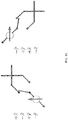
- FIGS. 10 and 11 illustrate an example dual-linear based 1-bit element having no phase delay ( FIG. 10 ) and a phase delay in one leg ( FIG. 11 ).
- the no phase delay embodiment only two phase states (0° and 180°) can be generated for any orientation of a linearly polarized field.
- the duplicated beam can be eliminated by modifying the radiating cell so that, when it is rotated, additional phase values can be generated.
- this can be done by adding a quarter wavelength transmission line to one of the ports of the radiating element.
- the addition of the quarter wave length transmission line can provide a 90° phase shift in the delay transmission line relative to the non-delayed transmission line.
- four phase states (0°, 90°, 180°, and 270°) can be generated for any orientation of a linearly polarized field.
- phase delay could be provided anywhere along the path or "leg" from the RE slot to within the switch.
- the phase delay difference can be provided on the connection between one of RE ports 211/212 and switch 120.
- the phase delay difference can be introduced internal to switch 120,
- the phase delay difference between the two legs associated with RE 110 can be created within RE 110, within switch 120, and/or between these two elements.
- the radiating cell can be a 1-bit radiating cell.
- the radiating cell can be controlled with a single bit control signal.
- the phase shifter can be a 1-bit phase shifter (single bit phase shifter).
- the phase shifter can be controlled with a 1-bit signal.
- one of two phase shifting states can be selected, where the difference between the two states can be the phase delay between the two ports of the phase shifter.
- radiating cell 101 and radiating cell 102 can be controlled by one or more controllers (not illustrated).
- the controllers can be any suitable controller configured to perform polarization control.
- each RE can be configured to perform electronic polarization control.
- the antenna arrays can have various arrangements and layouts of radiating Stated another way, the radiating elements or radiating cells can be laid out in a number of different ways.
- the antenna array can be a uniform array of radiating elements.
- the antenna array can be a non-uniform array of radiating elements.
- the array of radiating elements can be an aperiodic array.
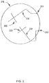
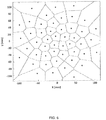
- the aperiodic array can be implemented as a spiral array lattice, a flower array lattice, a circular array lattice, or the like. Moreover, any suitable aperiodic array lattice can be used.
- FIG. 4 illustrates a mirrored Fibonacci-spiral configuration for an aperiodic array lattice.
- FIG. 5 illustrates an aperiodic array lattice implementing an unmirrored Fibonacci-spirals configuration.
- FIG. 6 illustrates a tapered aperiodic array lattice implementing an unmirrored Fibonacci-spirals configuration.
- non-rectangular lattices and in particular, aperiodic lattices, can be configured to reduce grating lobes when the array is scanned to a wide angle.
- the aperiodic distribution of the radiating elements can be configured to suppress both grating lobes and subarraying lobes.
- the radiating element arrangement can be uniform or approximately uniform such as with appropriately scaled Fibonacci spirals. See FIGS. 4 and 5 as examples.
- the radial positions of the elements in the array can be scaled to generate a particular side lobe profile in the radiation pattern.
- the structure of the Fibonacci spirals can be used to partition the beam forming network so that the sections for each spiral arm can be reused.
- the Fibonacci spiral can have the benefits of being relatively very even, as opposed to having a particular cell with relatively large amounts of free space about it while having another group of cells clustered together with relatively little free space about them.
- a uniform array can have relative rotation between radiating elements in the array and still be called a uniform array.
- each radiating cell (e.g., 101, 102) can comprise a switch 120.
- Switch 120 can be connected to second PS port 132.
- Switch 120 can be configured to be selectively connected to the first RE port 111 or the second RE port 112.
- each radiating cell only comprises a single switch.
- the single switch 120 can be a single pole, double throw switch.
- single switch 120 can comprise any suitable switch for selectively connecting second PS port 132 to first RE port 111 or second RE port 112.
- an antenna array can comprise at least two radiating cells, wherein each radiating cell can comprise a radiating element having two RE ports that can be selectively connected to a phase shifter.
- the radiating cell can further comprise a phase delay difference between the first and second radiating element ports.
- the first radiating cell 101 can be rotated relative to the second radiating cell 102.
- the switches and the phase shifters can be controlled by one or more controllers.
- the switches and the phase shifters can be controlled jointly to modify the antenna array radiation pattern as desired.
- the controller can control the radiation pattern to scan the beam at a particular direction or to turn the polarization to a desired angle.
- the rotation of radiating elements compared to other radiating elements can be configured to compensate for the reduction in the number of control bits used in the antenna array that result in limited phase states.
- the non-periodic array can generate a duplicated main beam that can halve the maximum directivity of the array.
- This duplicated main beam can be eliminated by a suitable rotation of the elements combined with a specific, fixed phase difference between the two ports of each element.
- the resulting 1-bit phased array can be configured to have a performance that scales with size along one or more of its dimensions: directivity, sidelobe levels, pointing errors, and polarization errors.
- the antenna array can be one of: a transmit antenna array, a receive antenna array, and a transceiver antenna array.
- the antenna array can be formed of monolithic microwave integrated circuits.
- the switch and/or phase shifter can be formed of discrete components.
- the antenna array can be configured to perform beam steering.
- an example method of controlling an antenna array can comprise receiving a first one-bit control signal to control a first phase shifter in a first radiating cell.
- the first radiating cell can comprise a first switch, the first phase shifter, and a first radiating element.
- the first radiating element can comprise a first radiating element port and a second radiating element port.
- the method can further comprise using the first switch to selectively connect the first phase shifter to one of the first radiating element port and the second radiating element port of the first radiating element
- the method can further comprise receiving a second one-bit control signal to control a second phase shifter in a second radiating cell.
- the second radiating cell can comprise a second switch, the second phase shifter, and a second radiating element.
- the second radiating element can comprise a third radiating element port and a fourth radiating element port.
- the method can further comprise using the second switch to selectively connect the second phase shifter to one of the third radiating element port and the fourth radiating element port of the second radiating element.
- the first radiating cell can be rotated relative to the second radiating cell.
- the method can further comprise providing a first phase delay difference between the signal paths associated with the first and second radiating element ports; and providing a second phase delay difference between the signal paths associated with the third and fourth radiating element ports.
Landscapes
- Variable-Direction Aerials And Aerial Arrays (AREA)
Claims (14)
- Antennengruppe (100), umfassend:eine erste Strahlungszelle (101) und eine zweite Strahlungszelle (102);wobei jede der ersten und zweiten Strahlungszelle umfasst:ein Strahlungselement (110);einen Phasenverschieber (130);einen Schalter (120), der zwischen dem Strahlungselement und dem Phasenverschieber verbunden ist, wobei der Schalter konfiguriert ist, den Phasenverschieber selektiv mit einem von einem ersten Strahlungselementanschluss (111) und einem zweiten Strahlungselementanschluss (112) des Strahlungselements zu verbinden; undeine Phasenverzögerungsdifferenz zwischen dem ersten und zweiten Strahlungselementanschluss,wobei die erste Strahlungszelle relativ zur zweiten Strahlungszelle gedreht ist,wobei der Phasenverschieber jeder der ersten und zweiten Strahlungszelle ein 1-Bit-Phasenverschieber ist.
- Antennengruppe nach Anspruch 1, wobei die Antennengruppe eine dritte Strahlungszelle umfasst, wobei die erste, zweite und dritte Strahlungszelle in der Antennengruppe in einem aperiodischen Gruppengitter angeordnet sind.
- Antennengruppe nach Anspruch 1, wobei das Strahlungselement jeder der ersten und zweiten Strahlungszelle mit nicht mehr als einem Schalter verknüpft ist und wobei die Antennengruppe eine dritte Strahlungszelle umfasst, wobei die Antennengruppe ein aperiodisches Gruppengitter ist, wobei das Strahlungselement jeder der ersten und zweiten Strahlungszelle ein duales lineares polarisiertes Strahlungselement ist, wobei das Strahlungselement jeder der ersten und zweiten Strahlungszelle eine elektronische Polarisationssteuerung hat.
- Antennengruppe nach Anspruch 1, wobei die erste Strahlungszelle eine erste physische Polarisationsorientierung hat, wobei die zweite Strahlungszelle eine zweite physische Polarisationsorientierung hat und wobei die erste physische Polarisationsorientierung relativ zur zweiten physischen Polarisationsorientierung gedreht ist.
- Antennengruppe nach Anspruch 1, wobei die Phasenverzögerungsdifferenz zwischen dem ersten und zweiten Strahlungselementanschluss etwa 90° ist.
- Antennengruppe nach Anspruch 1, wobei die erste und zweite Strahlungszelle ferner umfassen:eine erste Spur (220), die mit dem ersten Strahlungselementanschluss verknüpft und mit dem Phasenverschieber verbunden ist; undeine zweite Spur (230), die mit dem zweiten Strahlungselementanschluss verknüpft und mit dem Phasenverschieber verbunden ist;wobei die erste Spur eine erste Spurlänge hat und die zweite Spur eine zweite Spurlänge hat und wobei sich die erste Spurlänge von der zweiten Spurlänge unterscheidet, und wobei die Phasenverzögerungsdifferenz teilweise auf die Differenz zwischen der ersten Spurlänge und der zweiten Spurlänge zurückzuführen ist.
- Antennengruppe nach Anspruch 1, wobei das Strahlungselement jeder der ersten Strahlungszelle und der zweiten Strahlungszelle ferner enthält:ein erstes Antennenelement, das an den ersten Strahlungselementanschluss gekoppelt ist; undein zweites Antennenelement, das an den zweiten Strahlungselementanschluss gekoppelt ist.
- Antennengruppe nach Anspruch 7, wobei:das erste Antennenelement einer ersten Polarisation entspricht; unddas zweite Antennenelement einer zweiten Polarisation entspricht.
- Antennengruppe nach Anspruch 1, wobei der erste Strahlungselementanschluss der ersten Strahlungszelle einer ersten Polarisation entspricht und der zweite Strahlungselementanschluss der ersten Strahlungszelle einer zweiten Polarisation entspricht, die sich von der ersten Polarisation unterscheidet.
- Antennengruppe nach Anspruch 9, wobei der erste Strahlungselementanschluss des zweiten Strahlungselements einer dritten Polarisation entspricht, wobei sich die dritte Polarisation von der ersten Polarisation und der zweiten Polarisation unterscheidet.
- Antennengruppe nach Anspruch 9, wobei die erste Polarisation orthogonal zur zweiten Polarisation ist.
- Antennengruppe nach Anspruch 1, ferner umfassend zumindest eine Steuerung, um Befehle an den Phasenverschieber und den Schalter jeder der ersten und zweiten Strahlungszelle bereitzustellen.
- Antennengruppe nach Anspruch 12, wobei die bereitgestellten Befehle konfiguriert sind, einen Strahl von Signalen, der mit den mehreren Strahlungszellen kommuniziert wird, bei einem bestimmten Abtastwinkel abzutasten.
- Antennengruppe nach Anspruch 13, wobei die bereitgestellten Befehle konfiguriert sind, ferner eine Polarisation des Strahls auf einen bestimmten Polarisationswinkel zu drehen.
Applications Claiming Priority (2)
| Application Number | Priority Date | Filing Date | Title |
|---|---|---|---|
| US201261608987P | 2012-03-09 | 2012-03-09 | |
| PCT/US2013/029751 WO2013134585A2 (en) | 2012-03-09 | 2013-03-08 | Aperiodic phased array antenna with single bit phase shifters |
Publications (3)
| Publication Number | Publication Date |
|---|---|
| EP2823532A2 EP2823532A2 (de) | 2015-01-14 |
| EP2823532A4 EP2823532A4 (de) | 2016-07-27 |
| EP2823532B1 true EP2823532B1 (de) | 2018-03-07 |
Family
ID=49117514
Family Applications (1)
| Application Number | Title | Priority Date | Filing Date |
|---|---|---|---|
| EP13757406.7A Active EP2823532B1 (de) | 2012-03-09 | 2013-03-08 | Aperiodische phasengesteuerte gruppenantenne mit einzelbit-phasenverschiebern |
Country Status (3)
| Country | Link |
|---|---|
| US (3) | US10109916B2 (de) |
| EP (1) | EP2823532B1 (de) |
| WO (1) | WO2013134585A2 (de) |
Cited By (2)
| Publication number | Priority date | Publication date | Assignee | Title |
|---|---|---|---|---|
| US10109916B2 (en) | 2012-03-09 | 2018-10-23 | Viasat, Inc. | Aperiodic phased array antenna with single bit phase shifters |
| RU2796807C2 (ru) * | 2018-08-30 | 2023-05-29 | Виасат, Инк. | Антенная решетка с независимо вращающимися излучающими элементами |
Families Citing this family (19)
| Publication number | Priority date | Publication date | Assignee | Title |
|---|---|---|---|---|
| US9276314B2 (en) * | 2012-10-15 | 2016-03-01 | Electronics And Telecommunications Research Institute | Central node apparatus and method for transmitting wireless signals between central office node and remote node using beam patterns and antenna polarization |
| JP6980675B2 (ja) * | 2016-03-01 | 2021-12-15 | カイメタ コーポレイション | 移動アンテナを用いた衛星信号取得及び追跡 |
| US10884094B2 (en) | 2016-03-01 | 2021-01-05 | Kymeta Corporation | Acquiring and tracking a satellite signal with a scanned antenna |
| US10811784B2 (en) | 2016-03-01 | 2020-10-20 | Kymeta Corporation | Broadband RF radial waveguide feed with integrated glass transition |
| CL2016003302A1 (es) | 2016-12-22 | 2017-09-15 | Univ Chile | Dispositivo de radiovisión |
| US11621486B2 (en) | 2017-09-13 | 2023-04-04 | Metawave Corporation | Method and apparatus for an active radiating and feed structure |
| WO2019075488A1 (en) | 2017-10-15 | 2019-04-18 | Metawave Corporation | METHOD AND APPARATUS FOR AN ACTIVE RADIATION AND POWER STRUCTURE |
| US11201630B2 (en) * | 2017-11-17 | 2021-12-14 | Metawave Corporation | Method and apparatus for a frequency-selective antenna |
| US11265073B2 (en) * | 2017-11-28 | 2022-03-01 | Metawave Corporation | Method and apparatus for a metastructure reflector in a wireless communication system |
| US11450953B2 (en) | 2018-03-25 | 2022-09-20 | Metawave Corporation | Meta-structure antenna array |
| US11424548B2 (en) | 2018-05-01 | 2022-08-23 | Metawave Corporation | Method and apparatus for a meta-structure antenna array |
| US11342682B2 (en) | 2018-05-24 | 2022-05-24 | Metawave Corporation | Frequency-selective reflector module and system |
| US11710887B2 (en) * | 2018-05-31 | 2023-07-25 | Kymeta Corporation | Satellite signal acquisition |
| US11385326B2 (en) | 2018-06-13 | 2022-07-12 | Metawave Corporation | Hybrid analog and digital beamforming |
| US10553940B1 (en) * | 2018-08-30 | 2020-02-04 | Viasat, Inc. | Antenna array with independently rotated radiating elements |
| KR20210065153A (ko) * | 2018-10-02 | 2021-06-03 | 테크놀로지안 투트키무스케스쿠스 브이티티 오와이 | 고정 피드 안테나를 갖는 위상 어레이 안테나 시스템 |
| CN111510186B (zh) * | 2020-05-06 | 2024-04-26 | 中国电子科技集团公司第三十八研究所 | 一种非周期平面稀疏光控相控阵发射天线系统 |
| CN116325363A (zh) * | 2020-10-12 | 2023-06-23 | 华为技术有限公司 | 一种多频段共口径天线及通信设备 |
| CN113410657B (zh) * | 2021-06-11 | 2022-11-04 | 中国电子科技集团公司第三十八研究所 | 一种非周期天线阵列布阵方法及装置 |
Family Cites Families (12)
| Publication number | Priority date | Publication date | Assignee | Title |
|---|---|---|---|---|
| US20020167449A1 (en) * | 2000-10-20 | 2002-11-14 | Richard Frazita | Low profile phased array antenna |
| US7436370B2 (en) | 2005-10-14 | 2008-10-14 | L-3 Communications Titan Corporation | Device and method for polarization control for a phased array antenna |
| US8026863B2 (en) | 2006-10-11 | 2011-09-27 | Raytheon Company | Transmit/receive module communication and control architechture for active array |
| US7602337B2 (en) * | 2006-11-30 | 2009-10-13 | The Boeing Company | Antenna array including a phase shifter array controller and algorithm for steering the array |
| CN101971420B (zh) | 2008-02-04 | 2013-12-04 | 联邦科学和工业研究机构 | 圆形极化的阵列天线 |
| DE102008041356A1 (de) * | 2008-08-19 | 2010-02-25 | Robert Bosch Gmbh | Sensoranordnung |
| WO2010048174A1 (en) | 2008-10-20 | 2010-04-29 | Ems Technologies, Inc. | Antenna polarization control |
| US8085209B2 (en) * | 2009-04-02 | 2011-12-27 | Viasat, Inc. | Sub-array polarization control using rotated dual polarized radiating elements |
| US8344823B2 (en) * | 2009-08-10 | 2013-01-01 | Rf Controls, Llc | Antenna switching arrangement |
| US20110074646A1 (en) * | 2009-09-30 | 2011-03-31 | Snow Jeffrey M | Antenna array |
| US8279118B2 (en) * | 2009-09-30 | 2012-10-02 | The United States Of America As Represented By The Secretary Of The Navy | Aperiodic antenna array |
| EP2823532B1 (de) | 2012-03-09 | 2018-03-07 | ViaSat, Inc. | Aperiodische phasengesteuerte gruppenantenne mit einzelbit-phasenverschiebern |
-
2013
- 2013-03-08 EP EP13757406.7A patent/EP2823532B1/de active Active
- 2013-03-08 US US14/380,223 patent/US10109916B2/en active Active
- 2013-03-08 WO PCT/US2013/029751 patent/WO2013134585A2/en active Application Filing
-
2018
- 2018-09-20 US US16/137,327 patent/US10326202B2/en active Active
-
2019
- 2019-05-03 US US16/402,490 patent/US10553946B2/en active Active
Non-Patent Citations (1)
| Title |
|---|
| None * |
Cited By (4)
| Publication number | Priority date | Publication date | Assignee | Title |
|---|---|---|---|---|
| US10109916B2 (en) | 2012-03-09 | 2018-10-23 | Viasat, Inc. | Aperiodic phased array antenna with single bit phase shifters |
| US10326202B2 (en) | 2012-03-09 | 2019-06-18 | Viasat, Inc. | Aperiodic phased array antenna with single bit phase shifters |
| US10553946B2 (en) | 2012-03-09 | 2020-02-04 | Viasat, Inc. | Aperiodic phased array antenna with single bit phase shifters |
| RU2796807C2 (ru) * | 2018-08-30 | 2023-05-29 | Виасат, Инк. | Антенная решетка с независимо вращающимися излучающими элементами |
Also Published As
| Publication number | Publication date |
|---|---|
| WO2013134585A3 (en) | 2015-07-09 |
| US10553946B2 (en) | 2020-02-04 |
| US10109916B2 (en) | 2018-10-23 |
| EP2823532A2 (de) | 2015-01-14 |
| US20190296434A1 (en) | 2019-09-26 |
| US20150022421A1 (en) | 2015-01-22 |
| US20190051985A1 (en) | 2019-02-14 |
| US10326202B2 (en) | 2019-06-18 |
| WO2013134585A2 (en) | 2013-09-12 |
| EP2823532A4 (de) | 2016-07-27 |
Similar Documents
| Publication | Publication Date | Title |
|---|---|---|
| US10553946B2 (en) | Aperiodic phased array antenna with single bit phase shifters | |
| KR102507688B1 (ko) | 렌즈 안테나 시스템 | |
| Yang et al. | A study of phase quantization effects for reconfigurable reflectarray antennas | |
| JP6384550B2 (ja) | 無線通信モジュール | |
| US9391375B1 (en) | Wideband planar reconfigurable polarization antenna array | |
| US8159394B2 (en) | Selectable beam antenna | |
| Liu et al. | Circularly polarized 2 bit reconfigurable beam-steering antenna array | |
| EP2237373B1 (de) | Subarray-Polarisierungssteuerung unter Verwendung gedrehter, doppeltpolarisierter Strahlerelemente | |
| Zhu et al. | Wideband dual-polarized multiple beam-forming antenna arrays | |
| WO2020058916A1 (en) | Multi-band lens antenna system | |
| WO2008136715A1 (en) | A dual polarized antenna with null-fill | |
| Viganó et al. | Sparse array antenna for Ku-band mobile terminals using 1 bit phase controls | |
| US9780448B1 (en) | True path beam steering | |
| Lin et al. | A novel beam-switching array antenna using series-fed slots with PIN diodes | |
| Akbar et al. | Use of subarrays in linear array for improving wide angular scanning performance | |
| US11539146B2 (en) | Circular polarized phased array with wideband axial ratio bandwidth using sequential rotation and dynamic phase recovery | |
| Sharawi et al. | An electronically controlled 8-element switched beam planar array | |
| Afonin et al. | Antenna array of patch radiators with controlled polarization | |
| Yin et al. | A Modular 2-bit Subarray for Large-Scale Phased Array Antenna | |
| Walton et al. | Compact shipboard antenna system for simultaneous communication with three separate satellites | |
| Wu et al. | A compact polarization and pattern reconfigurable patch antenna by digital coding method | |
| KR102569685B1 (ko) | 다중 대역 안테나 및 그 제조방법 | |
| Fakoukakis et al. | On the design of a Butler matrix-based beamformer introducing low sidelobe level and enhanced beam-pointing accuracy | |
| Şahin et al. | Non-uniformly spaced planarphased array antenna for Ku-band mobile direct broadcasting satellite reception systems | |
| Chivukula et al. | Scalabel & Modular Circular Polarized Antenna Array for Digital Beamforming Applications |
Legal Events
| Date | Code | Title | Description |
|---|---|---|---|
| PUAI | Public reference made under article 153(3) epc to a published international application that has entered the european phase |
Free format text: ORIGINAL CODE: 0009012 |
|
| 17P | Request for examination filed |
Effective date: 20140813 |
|
| AK | Designated contracting states |
Kind code of ref document: A2 Designated state(s): AL AT BE BG CH CY CZ DE DK EE ES FI FR GB GR HR HU IE IS IT LI LT LU LV MC MK MT NL NO PL PT RO RS SE SI SK SM TR |
|
| AX | Request for extension of the european patent |
Extension state: BA ME |
|
| DAX | Request for extension of the european patent (deleted) | ||
| R17D | Deferred search report published (corrected) |
Effective date: 20150709 |
|
| A4 | Supplementary search report drawn up and despatched |
Effective date: 20160624 |
|
| RIC1 | Information provided on ipc code assigned before grant |
Ipc: H01Q 9/04 20060101ALN20160620BHEP Ipc: H01Q 21/20 20060101ALI20160620BHEP Ipc: H01Q 3/26 20060101ALI20160620BHEP Ipc: H01Q 21/00 20060101ALI20160620BHEP Ipc: H01Q 3/32 20060101AFI20160620BHEP Ipc: H01Q 3/38 20060101ALI20160620BHEP Ipc: H01Q 21/24 20060101ALI20160620BHEP Ipc: H01Q 21/06 20060101ALI20160620BHEP |
|
| REG | Reference to a national code |
Ref country code: DE Ref legal event code: R079 Ref document number: 602013034068 Country of ref document: DE Free format text: PREVIOUS MAIN CLASS: H01Q0003320000 Ipc: H01Q0003380000 |
|
| GRAP | Despatch of communication of intention to grant a patent |
Free format text: ORIGINAL CODE: EPIDOSNIGR1 |
|
| RIC1 | Information provided on ipc code assigned before grant |
Ipc: H01Q 21/06 20060101ALI20170822BHEP Ipc: H01Q 9/04 20060101ALN20170822BHEP Ipc: H01Q 21/20 20060101ALI20170822BHEP Ipc: H01Q 3/38 20060101AFI20170822BHEP Ipc: H01Q 21/24 20060101ALI20170822BHEP Ipc: H01Q 21/00 20060101ALI20170822BHEP |
|
| INTG | Intention to grant announced |
Effective date: 20170908 |
|
| GRAS | Grant fee paid |
Free format text: ORIGINAL CODE: EPIDOSNIGR3 |
|
| GRAA | (expected) grant |
Free format text: ORIGINAL CODE: 0009210 |
|
| AK | Designated contracting states |
Kind code of ref document: B1 Designated state(s): AL AT BE BG CH CY CZ DE DK EE ES FI FR GB GR HR HU IE IS IT LI LT LU LV MC MK MT NL NO PL PT RO RS SE SI SK SM TR |
|
| REG | Reference to a national code |
Ref country code: GB Ref legal event code: FG4D |
|
| REG | Reference to a national code |
Ref country code: CH Ref legal event code: EP Ref country code: AT Ref legal event code: REF Ref document number: 977488 Country of ref document: AT Kind code of ref document: T Effective date: 20180315 |
|
| REG | Reference to a national code |
Ref country code: IE Ref legal event code: FG4D |
|
| REG | Reference to a national code |
Ref country code: DE Ref legal event code: R096 Ref document number: 602013034068 Country of ref document: DE |
|
| REG | Reference to a national code |
Ref country code: FR Ref legal event code: PLFP Year of fee payment: 6 |
|
| REG | Reference to a national code |
Ref country code: NL Ref legal event code: MP Effective date: 20180307 |
|
| REG | Reference to a national code |
Ref country code: LT Ref legal event code: MG4D |
|
| PG25 | Lapsed in a contracting state [announced via postgrant information from national office to epo] |
Ref country code: CY Free format text: LAPSE BECAUSE OF FAILURE TO SUBMIT A TRANSLATION OF THE DESCRIPTION OR TO PAY THE FEE WITHIN THE PRESCRIBED TIME-LIMIT Effective date: 20180307 Ref country code: FI Free format text: LAPSE BECAUSE OF FAILURE TO SUBMIT A TRANSLATION OF THE DESCRIPTION OR TO PAY THE FEE WITHIN THE PRESCRIBED TIME-LIMIT Effective date: 20180307 Ref country code: NO Free format text: LAPSE BECAUSE OF FAILURE TO SUBMIT A TRANSLATION OF THE DESCRIPTION OR TO PAY THE FEE WITHIN THE PRESCRIBED TIME-LIMIT Effective date: 20180607 Ref country code: HR Free format text: LAPSE BECAUSE OF FAILURE TO SUBMIT A TRANSLATION OF THE DESCRIPTION OR TO PAY THE FEE WITHIN THE PRESCRIBED TIME-LIMIT Effective date: 20180307 Ref country code: LT Free format text: LAPSE BECAUSE OF FAILURE TO SUBMIT A TRANSLATION OF THE DESCRIPTION OR TO PAY THE FEE WITHIN THE PRESCRIBED TIME-LIMIT Effective date: 20180307 Ref country code: ES Free format text: LAPSE BECAUSE OF FAILURE TO SUBMIT A TRANSLATION OF THE DESCRIPTION OR TO PAY THE FEE WITHIN THE PRESCRIBED TIME-LIMIT Effective date: 20180307 |
|
| REG | Reference to a national code |
Ref country code: AT Ref legal event code: MK05 Ref document number: 977488 Country of ref document: AT Kind code of ref document: T Effective date: 20180307 |
|
| PG25 | Lapsed in a contracting state [announced via postgrant information from national office to epo] |
Ref country code: LV Free format text: LAPSE BECAUSE OF FAILURE TO SUBMIT A TRANSLATION OF THE DESCRIPTION OR TO PAY THE FEE WITHIN THE PRESCRIBED TIME-LIMIT Effective date: 20180307 Ref country code: SE Free format text: LAPSE BECAUSE OF FAILURE TO SUBMIT A TRANSLATION OF THE DESCRIPTION OR TO PAY THE FEE WITHIN THE PRESCRIBED TIME-LIMIT Effective date: 20180307 Ref country code: RS Free format text: LAPSE BECAUSE OF FAILURE TO SUBMIT A TRANSLATION OF THE DESCRIPTION OR TO PAY THE FEE WITHIN THE PRESCRIBED TIME-LIMIT Effective date: 20180307 Ref country code: BG Free format text: LAPSE BECAUSE OF FAILURE TO SUBMIT A TRANSLATION OF THE DESCRIPTION OR TO PAY THE FEE WITHIN THE PRESCRIBED TIME-LIMIT Effective date: 20180607 Ref country code: GR Free format text: LAPSE BECAUSE OF FAILURE TO SUBMIT A TRANSLATION OF THE DESCRIPTION OR TO PAY THE FEE WITHIN THE PRESCRIBED TIME-LIMIT Effective date: 20180608 |
|
| PG25 | Lapsed in a contracting state [announced via postgrant information from national office to epo] |
Ref country code: IT Free format text: LAPSE BECAUSE OF FAILURE TO SUBMIT A TRANSLATION OF THE DESCRIPTION OR TO PAY THE FEE WITHIN THE PRESCRIBED TIME-LIMIT Effective date: 20180307 Ref country code: NL Free format text: LAPSE BECAUSE OF FAILURE TO SUBMIT A TRANSLATION OF THE DESCRIPTION OR TO PAY THE FEE WITHIN THE PRESCRIBED TIME-LIMIT Effective date: 20180307 Ref country code: RO Free format text: LAPSE BECAUSE OF FAILURE TO SUBMIT A TRANSLATION OF THE DESCRIPTION OR TO PAY THE FEE WITHIN THE PRESCRIBED TIME-LIMIT Effective date: 20180307 Ref country code: EE Free format text: LAPSE BECAUSE OF FAILURE TO SUBMIT A TRANSLATION OF THE DESCRIPTION OR TO PAY THE FEE WITHIN THE PRESCRIBED TIME-LIMIT Effective date: 20180307 Ref country code: PL Free format text: LAPSE BECAUSE OF FAILURE TO SUBMIT A TRANSLATION OF THE DESCRIPTION OR TO PAY THE FEE WITHIN THE PRESCRIBED TIME-LIMIT Effective date: 20180307 Ref country code: AL Free format text: LAPSE BECAUSE OF FAILURE TO SUBMIT A TRANSLATION OF THE DESCRIPTION OR TO PAY THE FEE WITHIN THE PRESCRIBED TIME-LIMIT Effective date: 20180307 |
|
| REG | Reference to a national code |
Ref country code: CH Ref legal event code: PL |
|
| PG25 | Lapsed in a contracting state [announced via postgrant information from national office to epo] |
Ref country code: SM Free format text: LAPSE BECAUSE OF FAILURE TO SUBMIT A TRANSLATION OF THE DESCRIPTION OR TO PAY THE FEE WITHIN THE PRESCRIBED TIME-LIMIT Effective date: 20180307 Ref country code: SK Free format text: LAPSE BECAUSE OF FAILURE TO SUBMIT A TRANSLATION OF THE DESCRIPTION OR TO PAY THE FEE WITHIN THE PRESCRIBED TIME-LIMIT Effective date: 20180307 Ref country code: AT Free format text: LAPSE BECAUSE OF FAILURE TO SUBMIT A TRANSLATION OF THE DESCRIPTION OR TO PAY THE FEE WITHIN THE PRESCRIBED TIME-LIMIT Effective date: 20180307 Ref country code: CZ Free format text: LAPSE BECAUSE OF FAILURE TO SUBMIT A TRANSLATION OF THE DESCRIPTION OR TO PAY THE FEE WITHIN THE PRESCRIBED TIME-LIMIT Effective date: 20180307 |
|
| REG | Reference to a national code |
Ref country code: BE Ref legal event code: MM Effective date: 20180331 Ref country code: DE Ref legal event code: R097 Ref document number: 602013034068 Country of ref document: DE |
|
| REG | Reference to a national code |
Ref country code: IE Ref legal event code: MM4A |
|
| PG25 | Lapsed in a contracting state [announced via postgrant information from national office to epo] |
Ref country code: LU Free format text: LAPSE BECAUSE OF NON-PAYMENT OF DUE FEES Effective date: 20180308 Ref country code: PT Free format text: LAPSE BECAUSE OF FAILURE TO SUBMIT A TRANSLATION OF THE DESCRIPTION OR TO PAY THE FEE WITHIN THE PRESCRIBED TIME-LIMIT Effective date: 20180709 |
|
| PLBE | No opposition filed within time limit |
Free format text: ORIGINAL CODE: 0009261 |
|
| STAA | Information on the status of an ep patent application or granted ep patent |
Free format text: STATUS: NO OPPOSITION FILED WITHIN TIME LIMIT |
|
| PG25 | Lapsed in a contracting state [announced via postgrant information from national office to epo] |
Ref country code: MC Free format text: LAPSE BECAUSE OF FAILURE TO SUBMIT A TRANSLATION OF THE DESCRIPTION OR TO PAY THE FEE WITHIN THE PRESCRIBED TIME-LIMIT Effective date: 20180307 Ref country code: DK Free format text: LAPSE BECAUSE OF FAILURE TO SUBMIT A TRANSLATION OF THE DESCRIPTION OR TO PAY THE FEE WITHIN THE PRESCRIBED TIME-LIMIT Effective date: 20180307 Ref country code: IE Free format text: LAPSE BECAUSE OF NON-PAYMENT OF DUE FEES Effective date: 20180308 |
|
| 26N | No opposition filed |
Effective date: 20181210 |
|
| PG25 | Lapsed in a contracting state [announced via postgrant information from national office to epo] |
Ref country code: LI Free format text: LAPSE BECAUSE OF NON-PAYMENT OF DUE FEES Effective date: 20180331 Ref country code: BE Free format text: LAPSE BECAUSE OF NON-PAYMENT OF DUE FEES Effective date: 20180331 Ref country code: SI Free format text: LAPSE BECAUSE OF FAILURE TO SUBMIT A TRANSLATION OF THE DESCRIPTION OR TO PAY THE FEE WITHIN THE PRESCRIBED TIME-LIMIT Effective date: 20180307 Ref country code: CH Free format text: LAPSE BECAUSE OF NON-PAYMENT OF DUE FEES Effective date: 20180331 |
|
| PG25 | Lapsed in a contracting state [announced via postgrant information from national office to epo] |
Ref country code: MT Free format text: LAPSE BECAUSE OF NON-PAYMENT OF DUE FEES Effective date: 20180308 |
|
| PG25 | Lapsed in a contracting state [announced via postgrant information from national office to epo] |
Ref country code: TR Free format text: LAPSE BECAUSE OF FAILURE TO SUBMIT A TRANSLATION OF THE DESCRIPTION OR TO PAY THE FEE WITHIN THE PRESCRIBED TIME-LIMIT Effective date: 20180307 |
|
| PG25 | Lapsed in a contracting state [announced via postgrant information from national office to epo] |
Ref country code: HU Free format text: LAPSE BECAUSE OF FAILURE TO SUBMIT A TRANSLATION OF THE DESCRIPTION OR TO PAY THE FEE WITHIN THE PRESCRIBED TIME-LIMIT; INVALID AB INITIO Effective date: 20130308 |
|
| PG25 | Lapsed in a contracting state [announced via postgrant information from national office to epo] |
Ref country code: MK Free format text: LAPSE BECAUSE OF NON-PAYMENT OF DUE FEES Effective date: 20180307 |
|
| PG25 | Lapsed in a contracting state [announced via postgrant information from national office to epo] |
Ref country code: IS Free format text: LAPSE BECAUSE OF FAILURE TO SUBMIT A TRANSLATION OF THE DESCRIPTION OR TO PAY THE FEE WITHIN THE PRESCRIBED TIME-LIMIT Effective date: 20180707 |
|
| PGFP | Annual fee paid to national office [announced via postgrant information from national office to epo] |
Ref country code: FR Payment date: 20230327 Year of fee payment: 11 |
|
| PGFP | Annual fee paid to national office [announced via postgrant information from national office to epo] |
Ref country code: GB Payment date: 20230327 Year of fee payment: 11 Ref country code: DE Payment date: 20230329 Year of fee payment: 11 |
|
| P01 | Opt-out of the competence of the unified patent court (upc) registered |
Effective date: 20230529 |
|
| PGFP | Annual fee paid to national office [announced via postgrant information from national office to epo] |
Ref country code: DE Payment date: 20240327 Year of fee payment: 12 Ref country code: GB Payment date: 20240327 Year of fee payment: 12 |