EP2823191B1 - Magnetic pulse formed vehicle driveshaft and method of making same - Google Patents
Magnetic pulse formed vehicle driveshaft and method of making same Download PDFInfo
- Publication number
- EP2823191B1 EP2823191B1 EP13707490.2A EP13707490A EP2823191B1 EP 2823191 B1 EP2823191 B1 EP 2823191B1 EP 13707490 A EP13707490 A EP 13707490A EP 2823191 B1 EP2823191 B1 EP 2823191B1
- Authority
- EP
- European Patent Office
- Prior art keywords
- driveshaft
- insert
- splines
- female
- slip joint
- Prior art date
- Legal status (The legal status is an assumption and is not a legal conclusion. Google has not performed a legal analysis and makes no representation as to the accuracy of the status listed.)
- Not-in-force
Links
- 238000004519 manufacturing process Methods 0.000 title description 7
- 238000000034 method Methods 0.000 claims description 61
- 230000008569 process Effects 0.000 claims description 30
- 238000003466 welding Methods 0.000 claims description 25
- 238000003491 array Methods 0.000 claims description 12
- 239000000463 material Substances 0.000 claims description 10
- 229910045601 alloy Inorganic materials 0.000 claims description 6
- 239000000956 alloy Substances 0.000 claims description 6
- 239000007769 metal material Substances 0.000 claims description 6
- 230000006698 induction Effects 0.000 claims description 5
- 230000000295 complement effect Effects 0.000 claims description 2
- 238000005516 engineering process Methods 0.000 description 16
- 229910052751 metal Inorganic materials 0.000 description 14
- 239000002184 metal Substances 0.000 description 14
- 239000004519 grease Substances 0.000 description 12
- 238000002788 crimping Methods 0.000 description 11
- 239000003990 capacitor Substances 0.000 description 10
- 230000003628 erosive effect Effects 0.000 description 8
- 229910052782 aluminium Inorganic materials 0.000 description 7
- XAGFODPZIPBFFR-UHFFFAOYSA-N aluminium Chemical compound [Al] XAGFODPZIPBFFR-UHFFFAOYSA-N 0.000 description 7
- 238000010438 heat treatment Methods 0.000 description 7
- 239000004020 conductor Substances 0.000 description 5
- 238000001125 extrusion Methods 0.000 description 4
- 239000000314 lubricant Substances 0.000 description 4
- 239000000843 powder Substances 0.000 description 4
- 230000005540 biological transmission Effects 0.000 description 3
- 230000005672 electromagnetic field Effects 0.000 description 3
- RYGMFSIKBFXOCR-UHFFFAOYSA-N Copper Chemical compound [Cu] RYGMFSIKBFXOCR-UHFFFAOYSA-N 0.000 description 2
- 229910000831 Steel Inorganic materials 0.000 description 2
- 229910052802 copper Inorganic materials 0.000 description 2
- 239000010949 copper Substances 0.000 description 2
- 238000009826 distribution Methods 0.000 description 2
- 239000004033 plastic Substances 0.000 description 2
- 230000009467 reduction Effects 0.000 description 2
- 238000007493 shaping process Methods 0.000 description 2
- 239000010959 steel Substances 0.000 description 2
- 229910000755 6061-T6 aluminium alloy Inorganic materials 0.000 description 1
- 229910001369 Brass Inorganic materials 0.000 description 1
- 230000004913 activation Effects 0.000 description 1
- 230000000712 assembly Effects 0.000 description 1
- 238000000429 assembly Methods 0.000 description 1
- 239000011324 bead Substances 0.000 description 1
- 238000005452 bending Methods 0.000 description 1
- 230000009286 beneficial effect Effects 0.000 description 1
- 239000010951 brass Substances 0.000 description 1
- 239000011248 coating agent Substances 0.000 description 1
- 238000000576 coating method Methods 0.000 description 1
- 238000011109 contamination Methods 0.000 description 1
- 238000001816 cooling Methods 0.000 description 1
- 238000005260 corrosion Methods 0.000 description 1
- 230000007797 corrosion Effects 0.000 description 1
- 238000005520 cutting process Methods 0.000 description 1
- 238000010141 design making Methods 0.000 description 1
- 238000012938 design process Methods 0.000 description 1
- 238000007599 discharging Methods 0.000 description 1
- 238000004146 energy storage Methods 0.000 description 1
- 230000002349 favourable effect Effects 0.000 description 1
- 230000004907 flux Effects 0.000 description 1
- 238000007373 indentation Methods 0.000 description 1
- 230000003993 interaction Effects 0.000 description 1
- 238000005461 lubrication Methods 0.000 description 1
- 230000007246 mechanism Effects 0.000 description 1
- 230000004048 modification Effects 0.000 description 1
- 238000012986 modification Methods 0.000 description 1
- 230000000149 penetrating effect Effects 0.000 description 1
- 239000012254 powdered material Substances 0.000 description 1
- 230000035755 proliferation Effects 0.000 description 1
- 230000000717 retained effect Effects 0.000 description 1
- 125000006850 spacer group Chemical group 0.000 description 1
Images


Classifications
-
- F—MECHANICAL ENGINEERING; LIGHTING; HEATING; WEAPONS; BLASTING
- F16—ENGINEERING ELEMENTS AND UNITS; GENERAL MEASURES FOR PRODUCING AND MAINTAINING EFFECTIVE FUNCTIONING OF MACHINES OR INSTALLATIONS; THERMAL INSULATION IN GENERAL
- F16D—COUPLINGS FOR TRANSMITTING ROTATION; CLUTCHES; BRAKES
- F16D3/00—Yielding couplings, i.e. with means permitting movement between the connected parts during the drive
- F16D3/02—Yielding couplings, i.e. with means permitting movement between the connected parts during the drive adapted to specific functions
- F16D3/06—Yielding couplings, i.e. with means permitting movement between the connected parts during the drive adapted to specific functions specially adapted to allow axial displacement
-
- B—PERFORMING OPERATIONS; TRANSPORTING
- B23—MACHINE TOOLS; METAL-WORKING NOT OTHERWISE PROVIDED FOR
- B23K—SOLDERING OR UNSOLDERING; WELDING; CLADDING OR PLATING BY SOLDERING OR WELDING; CUTTING BY APPLYING HEAT LOCALLY, e.g. FLAME CUTTING; WORKING BY LASER BEAM
- B23K20/00—Non-electric welding by applying impact or other pressure, with or without the application of heat, e.g. cladding or plating
- B23K20/06—Non-electric welding by applying impact or other pressure, with or without the application of heat, e.g. cladding or plating by means of high energy impulses, e.g. magnetic energy
-
- F—MECHANICAL ENGINEERING; LIGHTING; HEATING; WEAPONS; BLASTING
- F16—ENGINEERING ELEMENTS AND UNITS; GENERAL MEASURES FOR PRODUCING AND MAINTAINING EFFECTIVE FUNCTIONING OF MACHINES OR INSTALLATIONS; THERMAL INSULATION IN GENERAL
- F16C—SHAFTS; FLEXIBLE SHAFTS; ELEMENTS OR CRANKSHAFT MECHANISMS; ROTARY BODIES OTHER THAN GEARING ELEMENTS; BEARINGS
- F16C3/00—Shafts; Axles; Cranks; Eccentrics
- F16C3/02—Shafts; Axles
- F16C3/03—Shafts; Axles telescopic
-
- F—MECHANICAL ENGINEERING; LIGHTING; HEATING; WEAPONS; BLASTING
- F16—ENGINEERING ELEMENTS AND UNITS; GENERAL MEASURES FOR PRODUCING AND MAINTAINING EFFECTIVE FUNCTIONING OF MACHINES OR INSTALLATIONS; THERMAL INSULATION IN GENERAL
- F16D—COUPLINGS FOR TRANSMITTING ROTATION; CLUTCHES; BRAKES
- F16D1/00—Couplings for rigidly connecting two coaxial shafts or other movable machine elements
- F16D1/06—Couplings for rigidly connecting two coaxial shafts or other movable machine elements for attachment of a member on a shaft or on a shaft-end
- F16D1/064—Couplings for rigidly connecting two coaxial shafts or other movable machine elements for attachment of a member on a shaft or on a shaft-end non-disconnectable
- F16D1/068—Couplings for rigidly connecting two coaxial shafts or other movable machine elements for attachment of a member on a shaft or on a shaft-end non-disconnectable involving gluing, welding or the like
-
- F—MECHANICAL ENGINEERING; LIGHTING; HEATING; WEAPONS; BLASTING
- F16—ENGINEERING ELEMENTS AND UNITS; GENERAL MEASURES FOR PRODUCING AND MAINTAINING EFFECTIVE FUNCTIONING OF MACHINES OR INSTALLATIONS; THERMAL INSULATION IN GENERAL
- F16D—COUPLINGS FOR TRANSMITTING ROTATION; CLUTCHES; BRAKES
- F16D1/00—Couplings for rigidly connecting two coaxial shafts or other movable machine elements
- F16D1/06—Couplings for rigidly connecting two coaxial shafts or other movable machine elements for attachment of a member on a shaft or on a shaft-end
- F16D1/08—Couplings for rigidly connecting two coaxial shafts or other movable machine elements for attachment of a member on a shaft or on a shaft-end with clamping hub; with hub and longitudinal key
- F16D1/0852—Couplings for rigidly connecting two coaxial shafts or other movable machine elements for attachment of a member on a shaft or on a shaft-end with clamping hub; with hub and longitudinal key with radial clamping between the mating surfaces of the hub and shaft
- F16D1/0858—Couplings for rigidly connecting two coaxial shafts or other movable machine elements for attachment of a member on a shaft or on a shaft-end with clamping hub; with hub and longitudinal key with radial clamping between the mating surfaces of the hub and shaft due to the elasticity of the hub (including shrink fits)
-
- F—MECHANICAL ENGINEERING; LIGHTING; HEATING; WEAPONS; BLASTING
- F16—ENGINEERING ELEMENTS AND UNITS; GENERAL MEASURES FOR PRODUCING AND MAINTAINING EFFECTIVE FUNCTIONING OF MACHINES OR INSTALLATIONS; THERMAL INSULATION IN GENERAL
- F16D—COUPLINGS FOR TRANSMITTING ROTATION; CLUTCHES; BRAKES
- F16D2250/00—Manufacturing; Assembly
- F16D2250/0061—Joining
-
- F—MECHANICAL ENGINEERING; LIGHTING; HEATING; WEAPONS; BLASTING
- F16—ENGINEERING ELEMENTS AND UNITS; GENERAL MEASURES FOR PRODUCING AND MAINTAINING EFFECTIVE FUNCTIONING OF MACHINES OR INSTALLATIONS; THERMAL INSULATION IN GENERAL
- F16D—COUPLINGS FOR TRANSMITTING ROTATION; CLUTCHES; BRAKES
- F16D2250/00—Manufacturing; Assembly
- F16D2250/0061—Joining
- F16D2250/0076—Welding, brazing
-
- F—MECHANICAL ENGINEERING; LIGHTING; HEATING; WEAPONS; BLASTING
- F16—ENGINEERING ELEMENTS AND UNITS; GENERAL MEASURES FOR PRODUCING AND MAINTAINING EFFECTIVE FUNCTIONING OF MACHINES OR INSTALLATIONS; THERMAL INSULATION IN GENERAL
- F16D—COUPLINGS FOR TRANSMITTING ROTATION; CLUTCHES; BRAKES
- F16D2300/00—Special features for couplings or clutches
- F16D2300/12—Mounting or assembling
-
- Y—GENERAL TAGGING OF NEW TECHNOLOGICAL DEVELOPMENTS; GENERAL TAGGING OF CROSS-SECTIONAL TECHNOLOGIES SPANNING OVER SEVERAL SECTIONS OF THE IPC; TECHNICAL SUBJECTS COVERED BY FORMER USPC CROSS-REFERENCE ART COLLECTIONS [XRACs] AND DIGESTS
- Y10—TECHNICAL SUBJECTS COVERED BY FORMER USPC
- Y10T—TECHNICAL SUBJECTS COVERED BY FORMER US CLASSIFICATION
- Y10T29/00—Metal working
- Y10T29/49—Method of mechanical manufacture
- Y10T29/49803—Magnetically shaping
-
- Y—GENERAL TAGGING OF NEW TECHNOLOGICAL DEVELOPMENTS; GENERAL TAGGING OF CROSS-SECTIONAL TECHNOLOGIES SPANNING OVER SEVERAL SECTIONS OF THE IPC; TECHNICAL SUBJECTS COVERED BY FORMER USPC CROSS-REFERENCE ART COLLECTIONS [XRACs] AND DIGESTS
- Y10—TECHNICAL SUBJECTS COVERED BY FORMER USPC
- Y10T—TECHNICAL SUBJECTS COVERED BY FORMER US CLASSIFICATION
- Y10T403/00—Joints and connections
- Y10T403/70—Interfitted members
- Y10T403/7026—Longitudinally splined or fluted rod
Definitions
- This invention relates to vehicular driveshaft assemblies and in particular to a method of forming a sliding spline-type joint using magnetic pulse forming technology.
- EP 1 698 787 A2 is regarded as the closest prior art to claim 1 and discloses a method of forming a sliding spline-type slip joint for use in a vehicle driveshaft comprising the steps of:
- EP 1 698 787 A2 is also regarded as the closest prior art to claim 8 and discloses a sliding spline-type slip joint for use in a vehicle driveshaft comprising:a female tubular driveshaft member comprising inward crimps and a male driveshaft member having a set of splines slidably engaged with said tubular insert, wherein said male driveshaft member is located within said female tubular driveshaft member
- the present invention relates to a driveshaft design and method of making same, capable of utilizing the advantages of magnetic pulse forming technology to simplify a driveshaft sliding spline-type joint and to eliminate electric erosion of the active working mandrel surface.
- Torque transmitting shafts are widely used for transferring rotational power from a source of rotational power to a rotatably driven mechanism.
- a drive train system is provided for transmitting rotational power from an output shaft of an engine/transmission assembly to an output shaft of an axle assembly so as to rotatably drive the wheels of the vehicle.
- a typical vehicular drive train system includes a hollow cylindrical driveshaft tube.
- a first universal joint is connected between the output shaft of the engine/transmission assembly and the first end of the driveshaft tube, while a second universal joint is connected between the second end of the driveshaft tube and the input shaft of the axle assembly.
- the universal joints provide a rotational driving connection from the output shaft of the engine/transmission assembly through the driveshaft tube to the input shaft of the axle assembly while accommodating a limited amount of misalignment between the rotational axes of the shafts.
- connection of the first driveshaft section and the second driveshaft section is typically accomplished by using a sliding spline-type slip joint having cooperating male and female members with respective pluralities of splines formed thereon.
- the male member is generally cylindrical in shape and has a plurality of outwardly extending splines formed on the outer surface thereof.
- the female member is generally hollow and cylindrical in shape and has a plurality of inwardly extending splines formed on the inner surface thereof.
- the male member is inserted within the female member such that the outwardly extending splines of the male member cooperate with the inwardly extending splines of the female member.
- the male and female members are connected together for concurrent rotation movement and for relative axial movement.
- the splines may be formed using magnetic pulse forming techniques.
- Magnetic pulse forming was developed as a means of shaping and assembling metal parts. The technology is especially convenient for treatment of tubular parts using cylindrical inductors, but also is capable of forming sheet metal with the help of flat inductors. If necessary, both forming and assembly can be executed in a single step.
- the materials that are the most easily formed by pulse magnetic field are ones that have a high electrical conductivity such as copper, brass and aluminum. Material with low conductivity can be formed if very high frequency pulses or driving rings made from aluminum or copper are used.
- magnetic pulse forming has several advantages: the process is easy to control, the forming tool (inductor) is not mechanically connected with the to-be-formed work piece (following no tooling indentations); the same inductor can be used to form parts of different shapes; forming can be made through insulated walls and vacuum; only one piece of tooling (mandrel or die) needs to be used; there is a very high specific pressure of forming; very high velocity of forming increases the metal plasticity, and there is high productivity.
- the basic disadvantages of magnetic pulse forming are: it is hard to perform deep elongation; it is practically impossible to form most types of steel without a driver and impossible to form parts when the free passage of electric current is restricted.
- Magnetic pulse forming technology uses a high voltage capacitor bank, a high current switch, a forming inductor, a high voltage power supply, and an electrically conductive work piece.
- the magnetic field is created by the discharge of the bank capacitor into the forming inductor.
- the work piece is typically placed very close to the inductor coil so that an eddy current is inducted into the work piece. From the moment the magnetic field is created, an eddy current is induced electromagnetically into the work piece in the opposite direction of the current of the coil.
- the interaction of the opposite flowing currents in the inductor coil and the work piece causes a mutual repulsion.
- the mutual repulsion causes a pressure impulse on the surfaces of the inductor coil and work piece.
- the inductor has to be mechanically very strong to withstand this pressure without deformation. So, the pulse of electromagnetic pressure causes high-velocity deformation of only the part of the work piece located under the inductor coil. That piece rapidly moves away from the coil until all the beginning kinetic energy is spent for deformation, or until the to-be-formed part collides with the shaping surfaces, for example the mandrel.
- the pulses of the magnet field are typically kept short to avoid reduction of magnetic pressure as a result of the magnetic field penetrating through the wall of the work piece. If the inductor is disposed about the exterior of the work piece, then the work piece can be deformed inwardly into engagement with the support surface of the mandrel to form the female splines. If, on the other hand, the inductor is disposed within the interior of the work piece, then the work piece can be deformed outwardly into engagement with the support surface to form the male splines.
- the most appropriate magnetic pulse forming machine is one with voltage of capacitor battery below 10 kV and frequency of the magnetic pulse about 10 kHz.
- the wall thickness of the typical aluminum driveshaft tube it 2.0 - 2.5 mm, it is inevitable that the magnetic field of this frequency will partly penetrate through the tube wall in the space between the internal tube surface and the supporting surfaces of the mandrel.
- the penetrated magnetic flux (the product of the average magnetic field times the perpendicular area that it penetrates) will be captured and compressed quickly in the gap.
- the present invention is directed toward a method of forming a sliding spline-type joint using magnetic pulse forming technology.
- a method of forming a sliding spline-type joint including providing a female tubular driveshaft member and a tubular splined insert having at least one array of inwardly formed splines.
- a male driveshaft member is provided having outwardly formed splines engageable with the splined insert, and a mandrel having outer ribs with a profile essentially the same as an outer spline profile of the male driveshaft member.
- An inductor is also provided which is capable of being energized to create a pulse magnetic field.
- the tubular splined insert is placed over the mandrel.
- the female tubular driveshaft member is disposed over the splined insert, and then both are placed coaxially inside the inductor.
- the inductor is energized to deform at least a portion of the female tubular driveshaft member over the insert to form at least one annular array of crimps for permanently connecting the female tubular driveshaft member with the insert.
- the female driveshaft member with the insert is removed from the inductor, and the male driveshaft member is engaged with and into the splined insert connected with the tubular female driveshaft member to provide a sliding spline type of slip joint.
- the driveshaft assembly 10 includes a female driveshaft tube 11 and a male driveshaft tube 12.
- a first end portion 13 of the male driveshaft tube 12 is received in a first end portion 14 of the female driveshaft tube 11 in a telescoping manner.
- a second end portion 15 of the male driveshaft tube 12 is connected to a first yoke 16.
- a second end portion 17 of the female driveshaft tube 11 is connected to a second yoke 18, such as by a magnetic pulse welding process.
- the first end portion 13 of the male driveshaft tube 12 has an annular array of radially outward extending splines or engaged segments 19. The engaged segments 19 extend continuously from the first end portion 13 to the second end portion 15, of the male driveshaft tube 12.
- an insert 20 is located which has a first and a second annular array of preliminarily formed axial splines 21, 22.
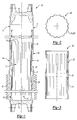
- a cross section of the insert 20 illustrating the two annular arrays of splines 21, 22 is shown in Fig. 2
- an axial section of the insert 20 again illustrating the splines 21, 22 is shown in Fig. 3 .
- the splines 21, 22 are aligned with one another, and there are an equal number of splines 21, 22 within each set. Within each set, the splines 21, 22 are equal in width, length and depth. The splines 21, 22 are spaced axially from each other and an annular pocket 23 is formed between the splines 21, 22, as depicted in Fig. 3 . The pocket 23 maintains a substantially equal length, depth and width around the insert 20, and it is also at the same axial distance around the insert 20. The splines 21, 22 may be flared to form a half bead at each end of the insert 20.
- FIG. 4 there is illustrated a portion of a cross section in the area of crimping an assembly that includes a mandrel 28, insert 20 and the first end portion 14 of the female driveshaft tube 11 before (bottom view) and after a magnetic pulse crimping operation (upper view).
- the surface of the mandrel 28 should be lubricated before putting the insert 20 over it to facilitate extracting the mandrel 28 from the insert 20 after magnetic pulse crimping.
- the insert 20 can be made from any suitable material or combination of materials and can have any suitable length.
- the splines 21, 22 in the insert 20 also can have any suitable length.
- the insert 20 should be formed from a metallic material or a metallic material alloy. Different technology of producing the splines 21, 22 in the insert 20 can be used that depend on the material and length of the insert 20 needed. For example, Grob process technology is very effective if the insert 20 is to be relatively long and is made from steel or other metal tubes.
- the insert 20 could be more effective if the insert 20 is to be short. It isn't mandatory for the insert 20 to be circularly closed in order to be strong against the radial force that affects it in the process of driveshaft operation in the vehicle. Actually, after magnetic pulse crimping, the first end 14 of the female driveshaft tube 11 will work against this radial force in the area of the slip joint. Because of that, the insert 20 could have a cut 29 as shown in Fig. 7 . Consequently, it could be easily produced from a metal band or metal sheet using cutting, stamping and banding operations separately or jointly to cut a work piece, for the splines 21, 22 and bend the insert 20 into a final circular shape.
- the edges of the cut 29 could be welded entirely or just tack welded to reinforce the desired circular shape. It is understood that different embodiments, material and technology can be used for producing the insert 20 without changing the scope of the given invention. The choice of technology is facilitated by the fact that the dimensional demands on the insert 20 are pretty low because the final shape of the splined areas 21, 22 of the insert 20 are defined by the shape of the mandrel 28 as a result of magnetic pulse crimping operations, which renders them very precise.
- Fig. 8 there is illustrated several versions of an axial section of a sliding spline-type of slip joint with different embodiments of the insert 20.
- the alternative embodiments are shown as 20a, 20b, 20c and 20d.
- the alternative embodiments provide different capabilities for retaining and distributing grease. It is well known that adequate lubrication is critically important to the proper operation of the sliding spline type of slip joint.
- grease is used as the lubricant.
- other lubricants could be used such as oil or a dry lubricant, for example.
- the lubricant supplied facilitates proper operation of the driveshaft assembly 10, and protects against corrosion and wear.
- embodiment 20a is an example of the Grob process for producing relatively long splines 21 a, 22a.
- this technology can provide only one pocket 23a to retain the grease, which potentially can cause axially non-uniform grease distribution along sliding surfaces if the distance of driveshaft slipping is small.
- More uniform axial grease distribution is provided by the shape of the insert 20d, which may have two grease pockets 23d, as is shown in the right bottom section of Fig. 8 .
- the splines 21 d, 22d are short.
- the Grob process isn't appropriate for this type of insert (it has inherent limitations by minimal length of the spline that can be formed).
- the insert 20d is best produced by using sheet metal.
- insert 20c The same technology looks used to produce 20d is also best for the embodiment of insert 20c, shown in the upper right section of Fig. 8 .
- insert 20c is short, when the driveshaft assembly 10 is assembled a very big pocket 23c is automatically created in the space between the first end portion 14 of the female driveshaft tube 11 and the first end portion 13 of the male driveshaft tube 12 (shown by the dotted line).
- the pocket 23c is available for the grease, but a large mass of grease, if it's circularly non-uniformly distributed, can misbalance the driveshaft. This is unacceptable because it may cause vehicle vibrations during operation and rotation of the driveshaft assembly.
- a sleeve 31 made from a grease penetrated material, felt for example, could be inserted in the process of assembling the driveshaft assembly 10.
- insert 20b is self lubricated because of an inherent property of the powdered materials.
- a bulge 32 can be made by any suitable method inside the extruded insert 20b after extrusion. Rings 33, 34 made from plastic or metal, may be used if necessary to precisely coaxially position the insert 20b relative to the first end portion 14 of the female driveshaft tube 11 during the magnetic pulse crimping operation.
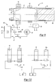
- FIG. 9 there is illustrated a portion of a control circuit indicated generally at 40, for performing a magnetic pulse forming process or magnetic pulse welding process.
- a control circuit indicated generally at 40, for performing a magnetic pulse forming process or magnetic pulse welding process.
- the position of the parts of the driveshaft assembly 10 are shown for the moment when the second end portion 17 of the female driveshaft tube 11 has already been welded with the second yoke 18 by a magnetic pulse welding method.
- the first end portion 14 of the female driveshaft tube 11 has a first and second annular array of the magnetic pulse formed crimps 24, 25, (as shown in Fig. 5 ) which are axially spaced from each other and provide a reliable connection between an internal surface of the first end portion 14 of the female driveshaft tube 11 with an outer surface of the insert 20.
- the outer surface of the engaged segments 19 of the first end portion 13 of the male driveshaft tube 12 are slidably connected with an internal surface of the splines 21, 22 formed in the insert 20. It is understood that additional annular arrays of the splines may be formed on the first end portion 14 of the female driveshaft tube 11 and insert 20 as desired.
- control circuit 40 is, of itself, conventional in the art, and the illustrated control circuit 40 is intended to be representative of any structure for performing a magnetic pulse forming process or magnetic pulse welding process. Thus, the scope of this invention is not intended to be limited for use with the control circuit 40 illustrated in Fig. 9 .
- the illustrated control circuit 40 includes an inductor coil 41 that is adapted to be disposed about the to-be-welded second end portion 17 of the female driveshaft tube 11.
- the inductor coil 41 can be formed having any desired structure, such as that shown and described in U.S. Pat. No. 4,129,846 to Yablochnikov, which is incorporated by reference herein.
- the inductor coil 41 is connected to the schematically illustrated control circuit 40 for selectively operating the same. To accomplish this, one end of the inductor coil 41 is connected to a first electrical conductor 42, while the other end of the inductor coil 41 is connected through a discharge switch 43 to a second electrical conductor 44. A plurality of high voltage capacitors 45, or other energy storage devices, are connected between the first and second electrical conductors 42, 44. The first electrical conductor 42 is also connected to a source of electrical power 46, while the second electrical conductor 44 is connected through a charging switch 47 to the source of the electrical power 46.
- the structure and operation of the control circuit is described in detail in U.S. Pat. No. 5,981,921 to Yablochnikov, which is incorporated by reference herein.
- the inductor coil 41 is operated by initially opening the discharge switch 43 and closing the charging switch 47, as shown in Fig. 9 . This allows electrical energy to be transformed from the source of electrical power 46 to each of the capacitors 45.
- the charging switch 47 is opened, as shown in Fig. 9 .
- the discharge switch 43 is closed.
- a high energy pulse of electrical current flows from the capacitors 45 through the inductor coil 41, thereby generating an immense and momentary electromagnetic field about or within a work piece.
- the inductor coil 41 is sized and shaped to be disposed concentrically about the female driveshaft tube 11.
- the inductor coil 41 may be used either to perform a magnetic pulse forming process, wherein the female driveshaft tube 11 is deformed to a desired shape, or a magnetic pulse welding process, wherein two metallic work pieces are permanently secured together, as described in detail above.
- This method could be used in this invention for magnetic pulse welding the second end portion 17 of the female driveshaft tube 11 and for magnetic pulse forming of the first and second annular array of magnetic pulse formed crimps 24, 25 on the first end portion 14 of the female driveshaft tube 11.
- a typical RHT, yield strength of 6061 T6 aluminum alloy dropped from 40 ksi to about 10 ksi, which permits significant reduction of the necessary energy of magnetic pulse for welding or forming ( U.S. Patent No. 4,766,664 to Alcoa , which is incorporated by reference herein.)
- a basic disadvantage of the RHT technique in its magnetic pulse welding application is the existence of the cooling step, in the process of which the heating energy - about 20 times greater than that of the magnetic pulse - is not only wasted but unavailable as a theoretically beneficial asset of the welding process. Indeed, to weld metal pieces, the surface atoms are activated by accepting any kind of energy. Heating is the most convenient and effective way to provide the atoms with the necessary energy for activation. So, theoretically, just preheating the tube ends should be better for magnetic pulse welding the driveshaft than using the RHT technique. Naturally, if preheating is used to facilitate the magnetic pulse welding it makes sense to use preheating to facilitate the magnetic pulse forming operation as is chosen in the present invention.
- the process of magnetic pulse welding starts with inserting the second end portion 17 of the female driveshaft tube 11 inside the preheating inductor 51 and inserting the neck of the second yoke 18 into the inductor coil 41. Inside the first end portion 14 of the female driveshaft tube 11 is located the insert 20, which is put onto the mandrel 28. It is understood that automatic tooling (not shown) is used for axially moving the driveshaft's parts in the process of magnetic pulse connection.
- the preheating inductor 51 is energized by the high frequency power supply 50, and the capacitors 45 of the control circuit 40 are charged to a predetermined voltage.
- the high frequency power supply 50 is switched off, and the female driveshaft tube 11 is instantly moved in an axial direction in the inductor coil 41 and is stopped at the moment the second end portion 17 of the female driveshaft tube 11 is correctly positioned.
- the inductor coil 41 is energized by means of discharging the capacitors 45 of the control circuit 40, which accomplishes the magnetic pulse cycle welding of the second end portion 17 of the female driveshaft tube 11 with the second yoke 18. It is also within the scope of the invention for the second yoke 18 to be attached to the second end portion 17 of the female driveshaft tube 11 in a separate step.
- the female driveshaft tube 11 together with the insert 20 and the mandrel 28 are axially moved left until the first end portion 14 of the female driveshaft tube 11 is properly located in the preheating inductor 51 to create the first and second annular array of magnetic pulse formed crimps 24, 25 on the first end portion 14 of the female driveshaft tube 11.
- the sequence of the heating and crimping operations is the same as is described above for welding, however, usually time or power of preheating is different and the energy of the magnetic pulse is lower.
- the sequence of the heating and crimping operations is repeated, but again, the parameters of heating and magnetic pulse could be corrected if necessary.
- a third and/or more rows of the crimps can be done the same way if necessary.
- the mandrel 28 is extracted from the insert 20 and the driveshaft assembly 10 is done.
- a two-stage magnetic pulse process can be used. For this it is necessary (see Fig. 10 ) to connect two pairs of preheating inductors 51 and inductor coils 41 in sequence, which can be closed or opened by switches 48, 52 depending on the type of operation performed - welding or forming. If a magnetic pulse welding operation is performed, the switches 48, 52 have to be closed. To perform the magnetic pulse crimp forming operation, switches 48, 52 have to be open. For one of ordinary skill in the art it's very easy to transform this layout using the parallel inductors connection.
- the preheating inductor 51 and the inductor coil 41 can be made long enough to provide just one row of relatively long crimps, if necessary. In some cases, for example, if the insert 20 is self-lubricated (made from the powder metal) this option could be practically justified.
- the first end portion 14 of the female driveshaft tube 11 was connected with the Grob processed insert 20b (see Fig. 8 ) by means of two rows of magnetic pulse formed crimps 24, 25 axially spaced at 90 mm from each other. Both, the welding and crimping operations were performed in three stages exactly as described above and shown in fig. 9 with the help of semiautomatic pneumatically actuated tooling and proper pulse power and induction heating equipment.
- the one-turn pulse inductor coil 41 and the control circuit 40 were made in accordance with U.S. Patent No. 4,129,846 .
- the high frequency power supply 50 provided power of 25 kW and frequency about 20 kHz with water-cooled two-turn preheating inductor 51.
- Time of preheating was 6 seconds for welding and 8 seconds for crimping.
- a high quality female driveshaft tube 11 was gotten as a result of those operations.
- a very good fit with the Grob-processed male tubular driveshaft member 12 and very low runout was gotten.
- the dimensions of all the crimp connections are very consistent.
- the present subject-matter includes, inter alia, the following aspects:
Landscapes
- Engineering & Computer Science (AREA)
- General Engineering & Computer Science (AREA)
- Mechanical Engineering (AREA)
- Ocean & Marine Engineering (AREA)
- Shafts, Cranks, Connecting Bars, And Related Bearings (AREA)
Description
- This invention relates to vehicular driveshaft assemblies and in particular to a method of forming a sliding spline-type joint using magnetic pulse forming technology.
-
EP 1 698 787 A2 - providing a female tubular driveshaft member,
- providing a male driveshaft member having outwardly formed splines
- providing a mandrel having outer ribs with a profile essentially the same as an outer spline profile of said male driveshaft member, and providing an inductor capable of being energized to create a pulse magnetic field;
- disposing said female tubular driveshaft member inside said inductor;
- energizing said inductor to deform at least a portion of said female tubular driveshaft member to form at least one annular array of crimps;
- removing said female driveshaft member from said mandrel and said inductor; and
- inserting said male driveshaft member into said tubular female driveshaft member to provide a sliding spline type of slip joint.
-
EP 1 698 787 A2 - The present invention relates to a driveshaft design and method of making same, capable of utilizing the advantages of magnetic pulse forming technology to simplify a driveshaft sliding spline-type joint and to eliminate electric erosion of the active working mandrel surface.
- Torque transmitting shafts (driveshafts) are widely used for transferring rotational power from a source of rotational power to a rotatably driven mechanism. For example, in most land vehicles in use today, a drive train system is provided for transmitting rotational power from an output shaft of an engine/transmission assembly to an output shaft of an axle assembly so as to rotatably drive the wheels of the vehicle. To accomplish this, a typical vehicular drive train system includes a hollow cylindrical driveshaft tube. A first universal joint is connected between the output shaft of the engine/transmission assembly and the first end of the driveshaft tube, while a second universal joint is connected between the second end of the driveshaft tube and the input shaft of the axle assembly. The universal joints provide a rotational driving connection from the output shaft of the engine/transmission assembly through the driveshaft tube to the input shaft of the axle assembly while accommodating a limited amount of misalignment between the rotational axes of the shafts.
- Where the driveshaft tube has two or more sections, connection of the first driveshaft section and the second driveshaft section is typically accomplished by using a sliding spline-type slip joint having cooperating male and female members with respective pluralities of splines formed thereon. The male member is generally cylindrical in shape and has a plurality of outwardly extending splines formed on the outer surface thereof. The female member is generally hollow and cylindrical in shape and has a plurality of inwardly extending splines formed on the inner surface thereof. The male member is inserted within the female member such that the outwardly extending splines of the male member cooperate with the inwardly extending splines of the female member. As a result, the male and female members are connected together for concurrent rotation movement and for relative axial movement.
- Theoretically, if the male and female members of the driveshaft are made from aluminum tubes, the splines may be formed using magnetic pulse forming techniques. Magnetic pulse forming was developed as a means of shaping and assembling metal parts. The technology is especially convenient for treatment of tubular parts using cylindrical inductors, but also is capable of forming sheet metal with the help of flat inductors. If necessary, both forming and assembly can be executed in a single step. The materials that are the most easily formed by pulse magnetic field are ones that have a high electrical conductivity such as copper, brass and aluminum. Material with low conductivity can be formed if very high frequency pulses or driving rings made from aluminum or copper are used.
- In comparison with other metal forming methods, magnetic pulse forming has several advantages: the process is easy to control, the forming tool (inductor) is not mechanically connected with the to-be-formed work piece (following no tooling indentations); the same inductor can be used to form parts of different shapes; forming can be made through insulated walls and vacuum; only one piece of tooling (mandrel or die) needs to be used; there is a very high specific pressure of forming; very high velocity of forming increases the metal plasticity, and there is high productivity. The basic disadvantages of magnetic pulse forming are: it is hard to perform deep elongation; it is practically impossible to form most types of steel without a driver and impossible to form parts when the free passage of electric current is restricted.
- Magnetic pulse forming technology uses a high voltage capacitor bank, a high current switch, a forming inductor, a high voltage power supply, and an electrically conductive work piece. The magnetic field is created by the discharge of the bank capacitor into the forming inductor. The work piece is typically placed very close to the inductor coil so that an eddy current is inducted into the work piece. From the moment the magnetic field is created, an eddy current is induced electromagnetically into the work piece in the opposite direction of the current of the coil. The interaction of the opposite flowing currents in the inductor coil and the work piece causes a mutual repulsion. The mutual repulsion causes a pressure impulse on the surfaces of the inductor coil and work piece. The inductor has to be mechanically very strong to withstand this pressure without deformation. So, the pulse of electromagnetic pressure causes high-velocity deformation of only the part of the work piece located under the inductor coil. That piece rapidly moves away from the coil until all the beginning kinetic energy is spent for deformation, or until the to-be-formed part collides with the shaping surfaces, for example the mandrel. The pulses of the magnet field are typically kept short to avoid reduction of magnetic pressure as a result of the magnetic field penetrating through the wall of the work piece. If the inductor is disposed about the exterior of the work piece, then the work piece can be deformed inwardly into engagement with the support surface of the mandrel to form the female splines. If, on the other hand, the inductor is disposed within the interior of the work piece, then the work piece can be deformed outwardly into engagement with the support surface to form the male splines.
- However, it is hard to realize the described technique in practice, especially under the high volume production conditions typical for manufacturing driveshafts. Indeed, from the point of view of efficiency, reliability and safety, to form the splines of aluminum tubes, the most appropriate magnetic pulse forming machine is one with voltage of capacitor battery below 10 kV and frequency of the magnetic pulse about 10 kHz. But because the wall thickness of the typical aluminum driveshaft tube it 2.0 - 2.5 mm, it is inevitable that the magnetic field of this frequency will partly penetrate through the tube wall in the space between the internal tube surface and the supporting surfaces of the mandrel. In the process of high velocity tube deformation, the penetrated magnetic flux (the product of the average magnetic field times the perpendicular area that it penetrates) will be captured and compressed quickly in the gap. As a result, very high opposing currents will be induced along the perimeter of those surfaces and at the moment the tube collides about the mandrel, electric erosion of the contact surfaces occurs. The erosion is especially intense in the bottom of the mandrel grooves, where the tops of the splines are in contact first. This electric erosion destroys the active mandrel surface very fast. Electric erosion of these surfaces is the main restriction to wide proliferation of magnetic pulse forming technology in applications where mandrels/dies have to be used. Theoretically the mandrel surface could be protected from erosion by using dielectric coating or spacers, for example. Also a higher frequency and resultant higher voltage magnetic pulse machine could reduce the intensity of erosion. But it is technically difficult and expensive to realize those opportunities to cure the problem in practice.
- The present invention is directed toward a method of forming a sliding spline-type joint using magnetic pulse forming technology. According to this invention there is provided a method of forming a sliding spline-type joint, the method including providing a female tubular driveshaft member and a tubular splined insert having at least one array of inwardly formed splines. A male driveshaft member is provided having outwardly formed splines engageable with the splined insert, and a mandrel having outer ribs with a profile essentially the same as an outer spline profile of the male driveshaft member. An inductor is also provided which is capable of being energized to create a pulse magnetic field. The tubular splined insert is placed over the mandrel. The female tubular driveshaft member is disposed over the splined insert, and then both are placed coaxially inside the inductor. The inductor is energized to deform at least a portion of the female tubular driveshaft member over the insert to form at least one annular array of crimps for permanently connecting the female tubular driveshaft member with the insert. The female driveshaft member with the insert is removed from the inductor, and the male driveshaft member is engaged with and into the splined insert connected with the tubular female driveshaft member to provide a sliding spline type of slip joint.
- In accordance with the present invention, it is highly desirable to develop a driveshaft design and manufacturing process capable of utilizing the advantages of magnetic pulse forming technology to simplify a driveshaft sliding spline-type slip joint and to eliminate electric erosion of the working mandrel surface.
- The above, as well as other advantages of the present invention, will become readily apparent to those skilled in the art from the following detailed description when considered in the light of the accompanying drawings in which:
-
Fig. 1 is an axial section view of a vehicle driveshaft in accordance with the present invention; -
Fig. 2 is a cross section view of the insert shown inFig. 1 along line 2-2; -
Fig. 3 is an axial section view of the insert shown inFig. 1 ; -
Fig. 4 is part of a cross sectional view of a mandrel, insert and female tube assembly prior and subsequent to application of the magnetic pulse; -
Fig. 5 is part of a cross sectional view of the driveshaft shown inFig. 1 ; -
Fig. 6 is an axial sectional view of another embodiment of theinsert 20b, shown inFig. 8 ; -
Fig. 7 is an axial sectional view of another embodiment of theinsert 20c, shown inFig. 8 ; -
Fig. 8 illustrates different embodiments of the sliding spline-type slip joint shown inFig. 1 ; -
Fig. 9 is an illustration of a device and process; -
Fig. 10 is an illustration of a device and process in accordance with this invention. - It is to be understood that the invention may assume various alternative orientations and step sequences, except where expressly specified to the contrary. It is also to be understood that the specific devices and processes illustrated in the attached drawings, and described in the following specification are simply exemplary embodiments of the inventive concepts defined in the appended claims. Hence, specific dimensions, directions or other physical characteristics relating to the embodiments disclosed are not to be considered as limiting, unless the claims expressly state otherwise.
- Referring now to the drawings and particular to
Fig. 1 , there is shown generally at 10 a driveshaft assembly having a sliding spline-type of slip joint. Thedriveshaft assembly 10 includes afemale driveshaft tube 11 and amale driveshaft tube 12. Afirst end portion 13 of themale driveshaft tube 12 is received in afirst end portion 14 of thefemale driveshaft tube 11 in a telescoping manner. Asecond end portion 15 of themale driveshaft tube 12 is connected to afirst yoke 16. Asecond end portion 17 of thefemale driveshaft tube 11 is connected to asecond yoke 18, such as by a magnetic pulse welding process. Thefirst end portion 13 of themale driveshaft tube 12 has an annular array of radially outward extending splines or engagedsegments 19. The engagedsegments 19 extend continuously from thefirst end portion 13 to thesecond end portion 15, of themale driveshaft tube 12. - Between the
first end 13 portion of themale driveshaft tube 12 and thefirst end portion 14 of thefemale driveshaft tube 11 aninsert 20 is located which has a first and a second annular array of preliminarily formedaxial splines insert 20 illustrating the two annular arrays ofsplines Fig. 2 , and an axial section of theinsert 20 again illustrating thesplines Fig. 3 . - As depicted in
Fig. 2 , thesplines splines splines splines annular pocket 23 is formed between thesplines Fig. 3 . Thepocket 23 maintains a substantially equal length, depth and width around theinsert 20, and it is also at the same axial distance around theinsert 20. Thesplines insert 20. - Referring now to
Fig. 4 , there is illustrated a portion of a cross section in the area of crimping an assembly that includes amandrel 28, insert 20 and thefirst end portion 14 of thefemale driveshaft tube 11 before (bottom view) and after a magnetic pulse crimping operation (upper view). The surface of themandrel 28 should be lubricated before putting theinsert 20 over it to facilitate extracting themandrel 28 from theinsert 20 after magnetic pulse crimping. - The
insert 20 can be made from any suitable material or combination of materials and can have any suitable length. Thesplines insert 20 also can have any suitable length. Typically, theinsert 20 should be formed from a metallic material or a metallic material alloy. Different technology of producing thesplines insert 20 can be used that depend on the material and length of theinsert 20 needed. For example, Grob process technology is very effective if theinsert 20 is to be relatively long and is made from steel or other metal tubes. - However, metal powder or extrusion technologies could be more effective if the
insert 20 is to be short. It isn't mandatory for theinsert 20 to be circularly closed in order to be strong against the radial force that affects it in the process of driveshaft operation in the vehicle. Actually, after magnetic pulse crimping, thefirst end 14 of thefemale driveshaft tube 11 will work against this radial force in the area of the slip joint. Because of that, theinsert 20 could have acut 29 as shown inFig. 7 . Consequently, it could be easily produced from a metal band or metal sheet using cutting, stamping and banding operations separately or jointly to cut a work piece, for thesplines insert 20 into a final circular shape. - If it's necessary to more precisely retain the circular shape of the
insert 20 after bending it into a circle, the edges of thecut 29 could be welded entirely or just tack welded to reinforce the desired circular shape. It is understood that different embodiments, material and technology can be used for producing theinsert 20 without changing the scope of the given invention. The choice of technology is facilitated by the fact that the dimensional demands on theinsert 20 are pretty low because the final shape of thesplined areas insert 20 are defined by the shape of themandrel 28 as a result of magnetic pulse crimping operations, which renders them very precise. - Referring now to
Fig. 8 , there is illustrated several versions of an axial section of a sliding spline-type of slip joint with different embodiments of theinsert 20. The alternative embodiments are shown as 20a, 20b, 20c and 20d. The alternative embodiments provide different capabilities for retaining and distributing grease. It is well known that adequate lubrication is critically important to the proper operation of the sliding spline type of slip joint. Typically, grease is used as the lubricant. However, it is understood that other lubricants could be used such as oil or a dry lubricant, for example. The lubricant supplied facilitates proper operation of thedriveshaft assembly 10, and protects against corrosion and wear. -
Fig. 8 ,embodiment 20a is an example of the Grob process for producing relatively long splines 21 a, 22a. However, in practice this technology can provide only one pocket 23a to retain the grease, which potentially can cause axially non-uniform grease distribution along sliding surfaces if the distance of driveshaft slipping is small. - More uniform axial grease distribution is provided by the shape of the
insert 20d, which may have two grease pockets 23d, as is shown in the right bottom section ofFig. 8 . In this embodiment the splines 21 d, 22d are short. The Grob process isn't appropriate for this type of insert (it has inherent limitations by minimal length of the spline that can be formed). Theinsert 20d is best produced by using sheet metal. - The same technology looks used to produce 20d is also best for the embodiment of
insert 20c, shown in the upper right section ofFig. 8 . In this case because theinsert 20c is short, when thedriveshaft assembly 10 is assembled a verybig pocket 23c is automatically created in the space between thefirst end portion 14 of thefemale driveshaft tube 11 and thefirst end portion 13 of the male driveshaft tube 12 (shown by the dotted line). Thepocket 23c is available for the grease, but a large mass of grease, if it's circularly non-uniformly distributed, can misbalance the driveshaft. This is unacceptable because it may cause vehicle vibrations during operation and rotation of the driveshaft assembly. To avoid misbalance, asleeve 31 made from a grease penetrated material, felt for example, could be inserted in the process of assembling thedriveshaft assembly 10. - The extrusion method or powder metal technologies are best to produce the embodiment of
insert 20b shown in the upper left section ofFig. 8 . Made from powder metal,insert 20b is self lubricated because of an inherent property of the powdered materials. In this embodiment to retain the grease, ifinsert 20b is made by the extrusion method, abulge 32 can be made by any suitable method inside the extrudedinsert 20b after extrusion.Rings 33, 34 made from plastic or metal, may be used if necessary to precisely coaxially position theinsert 20b relative to thefirst end portion 14 of thefemale driveshaft tube 11 during the magnetic pulse crimping operation. - Referring now to
Fig. 9 , there is illustrated a portion of a control circuit indicated generally at 40, for performing a magnetic pulse forming process or magnetic pulse welding process. For simplicity of the drawing, the position of the parts of thedriveshaft assembly 10 are shown for the moment when thesecond end portion 17 of thefemale driveshaft tube 11 has already been welded with thesecond yoke 18 by a magnetic pulse welding method. - The
first end portion 14 of thefemale driveshaft tube 11 has a first and second annular array of the magnetic pulse formed crimps 24, 25, (as shown inFig. 5 ) which are axially spaced from each other and provide a reliable connection between an internal surface of thefirst end portion 14 of thefemale driveshaft tube 11 with an outer surface of theinsert 20. The outer surface of the engagedsegments 19 of thefirst end portion 13 of themale driveshaft tube 12 are slidably connected with an internal surface of thesplines insert 20. It is understood that additional annular arrays of the splines may be formed on thefirst end portion 14 of thefemale driveshaft tube 11 and insert 20 as desired. In the last casemore pockets 23 will be automatically formed in theinsert 20, as is most clearly illustrated in the different embodiments depicted onFig. 8 . After assembling thedriveshaft assembly 10, grease will accumulate and be retained in thepockets 23 of the sliding spline-type of slip joint. This grease will distribute along the contact surfaces of the engagedsegments 19 of thefirst end portion 13 of themale driveshaft tube 12, and thesplines insert 20 in the process of sliding, which is highly favorable for the functionality of the life of the slip joint. A rubber orplastic boot 27 may be used to protect all the parts of the sliding spline-type of slip joint from contamination, as shown inFig. 8 . - The
control circuit 40 is, of itself, conventional in the art, and the illustratedcontrol circuit 40 is intended to be representative of any structure for performing a magnetic pulse forming process or magnetic pulse welding process. Thus, the scope of this invention is not intended to be limited for use with thecontrol circuit 40 illustrated inFig. 9 . - The illustrated
control circuit 40 includes aninductor coil 41 that is adapted to be disposed about the to-be-weldedsecond end portion 17 of thefemale driveshaft tube 11. Theinductor coil 41 can be formed having any desired structure, such as that shown and described inU.S. Pat. No. 4,129,846 to Yablochnikov, which is incorporated by reference herein. - The
inductor coil 41 is connected to the schematically illustratedcontrol circuit 40 for selectively operating the same. To accomplish this, one end of theinductor coil 41 is connected to a firstelectrical conductor 42, while the other end of theinductor coil 41 is connected through adischarge switch 43 to a secondelectrical conductor 44. A plurality ofhigh voltage capacitors 45, or other energy storage devices, are connected between the first and secondelectrical conductors electrical conductor 42 is also connected to a source ofelectrical power 46, while the secondelectrical conductor 44 is connected through a chargingswitch 47 to the source of theelectrical power 46. The structure and operation of the control circuit is described in detail inU.S. Pat. No. 5,981,921 to Yablochnikov, which is incorporated by reference herein. - The operation of the
inductor coil 41 to perform the magnetic pulse welding process or a magnetic pulse forming process is well known in the art, and reference is again made to the above-referenced patents for a detailed explanation. Briefly, however, theinductor coil 41 is operated by initially opening thedischarge switch 43 and closing the chargingswitch 47, as shown inFig. 9 . This allows electrical energy to be transformed from the source ofelectrical power 46 to each of thecapacitors 45. When thecapacitors 45 have been charged to a predetermined voltage, the chargingswitch 47 is opened, as shown inFig. 9 . Thereafter, when it is desired to energize theinductor coil 41, thedischarge switch 43 is closed. As a result, a high energy pulse of electrical current flows from thecapacitors 45 through theinductor coil 41, thereby generating an immense and momentary electromagnetic field about or within a work piece. - In the illustrated embodiment, the
inductor coil 41 is sized and shaped to be disposed concentrically about thefemale driveshaft tube 11. Thus, when theinductor coil 41 is energized and the electromagnetic field is generated, a very large force is exerted on the outer surface of thefemale driveshaft tube 11, causing it to collapse inwardly away from theinductor coil 41. Depending upon the magnitude of the electromagnetic field that is generated and other factors, theinductor coil 41 may be used either to perform a magnetic pulse forming process, wherein thefemale driveshaft tube 11 is deformed to a desired shape, or a magnetic pulse welding process, wherein two metallic work pieces are permanently secured together, as described in detail above. - It's well known that increasing the plasticity of a to-be-welded or to-be-formed tube significantly reduces wear out of all the elements of the
control circuit 40 because to provide a good quality joint by magnetic pulse welding or crimping, less energy of the magnetic pulse needs to be used. Today, the most popular method of reducing the necessary energy of the magnetic pulse is based on reducing the material yield strength by means of the technique known as retrogressive heat treatment (RHT). - This method could be used in this invention for magnetic pulse welding the
second end portion 17 of thefemale driveshaft tube 11 and for magnetic pulse forming of the first and second annular array of magnetic pulse formed crimps 24, 25 on thefirst end portion 14 of thefemale driveshaft tube 11. A typical RHT, yield strength of 6061 T6 aluminum alloy dropped from 40 ksi to about 10 ksi, which permits significant reduction of the necessary energy of magnetic pulse for welding or forming (U.S. Patent No. 4,766,664 to Alcoa , which is incorporated by reference herein.) - A basic disadvantage of the RHT technique in its magnetic pulse welding application is the existence of the cooling step, in the process of which the heating energy - about 20 times greater than that of the magnetic pulse - is not only wasted but unavailable as a theoretically beneficial asset of the welding process. Indeed, to weld metal pieces, the surface atoms are activated by accepting any kind of energy. Heating is the most convenient and effective way to provide the atoms with the necessary energy for activation. So, theoretically, just preheating the tube ends should be better for magnetic pulse welding the driveshaft than using the RHT technique. Naturally, if preheating is used to facilitate the magnetic pulse welding it makes sense to use preheating to facilitate the magnetic pulse forming operation as is chosen in the present invention.
- Most of the truly important innovation related to induction preheating in magnetic pulse technology was suggested more than 40 years ago in
U.S. patent No. 3,126,937 to Brower and Fortescue , which is incorporated by reference herein. There are scores of patents related to induction preheating in the different magnetic pulse processes and this method of preheating is used in the present invention. For this a highfrequency power supply 50 and preheatinginductor 51 are used, as shown inFig. 9 . - The process of magnetic pulse welding, starts with inserting the
second end portion 17 of thefemale driveshaft tube 11 inside the preheatinginductor 51 and inserting the neck of thesecond yoke 18 into theinductor coil 41. Inside thefirst end portion 14 of thefemale driveshaft tube 11 is located theinsert 20, which is put onto themandrel 28. It is understood that automatic tooling (not shown) is used for axially moving the driveshaft's parts in the process of magnetic pulse connection. The preheatinginductor 51 is energized by the highfrequency power supply 50, and thecapacitors 45 of thecontrol circuit 40 are charged to a predetermined voltage. After preheating thesecond end portion 17 of thefemale driveshaft tube 11 to a predetermined temperature, the highfrequency power supply 50 is switched off, and thefemale driveshaft tube 11 is instantly moved in an axial direction in theinductor coil 41 and is stopped at the moment thesecond end portion 17 of thefemale driveshaft tube 11 is correctly positioned. Theinductor coil 41 is energized by means of discharging thecapacitors 45 of thecontrol circuit 40, which accomplishes the magnetic pulse cycle welding of thesecond end portion 17 of thefemale driveshaft tube 11 with thesecond yoke 18. It is also within the scope of the invention for thesecond yoke 18 to be attached to thesecond end portion 17 of thefemale driveshaft tube 11 in a separate step. - After that, the
female driveshaft tube 11 together with theinsert 20 and themandrel 28 are axially moved left until thefirst end portion 14 of thefemale driveshaft tube 11 is properly located in the preheatinginductor 51 to create the first and second annular array of magnetic pulse formed crimps 24, 25 on thefirst end portion 14 of thefemale driveshaft tube 11. The sequence of the heating and crimping operations is the same as is described above for welding, however, usually time or power of preheating is different and the energy of the magnetic pulse is lower. After creating one row of crimps all the assembly is retuned back into the preheatinginductor 51 and stopped in the new axial position that is indexed the distance equal to the space between the first and second annular array of magnetic pulse formed crimps 24, 25 on thefirst end portion 14 of thefemale driveshaft tube 11. - Next, the sequence of the heating and crimping operations is repeated, but again, the parameters of heating and magnetic pulse could be corrected if necessary. A third and/or more rows of the crimps can be done the same way if necessary. Finally, the
mandrel 28 is extracted from theinsert 20 and thedriveshaft assembly 10 is done. - From the foregoing description, one of ordinary skill in the art can easily ascertain the essential characteristics of this invention and, without departing from the spirit and scope thereof, can make various changes and modification to the invention to adapt it to various usage and conditions. For example, the described three state sequence of the magnetic pulse operation isn't optimal for high volume production of driveshafts. It is easy to see that those three stages can be made simultaneously if three pairs of preheating inductors and inductor coils are used. Naturally, the power supplies to energize the inductors have to be properly charged, which makes the production equipment significantly more expensive.
- As an intermediate, much cheaper choice, a two-stage magnetic pulse process can be used. For this it is necessary (see
Fig. 10 ) to connect two pairs of preheatinginductors 51 and inductor coils 41 in sequence, which can be closed or opened byswitches switches - Also, it's obvious that in the case of using any other method of welding instead of magnetic pulse welding to connect the
second end portion 17 of thefemale driveshaft tube 11 with thesecond yoke 18, the preheatinginductor 51 and theinductor coil 41 can be made long enough to provide just one row of relatively long crimps, if necessary. In some cases, for example, if theinsert 20 is self-lubricated (made from the powder metal) this option could be practically justified. - Example: The
second end portion 17 of thefemale driveshaft tube 11 with an outer diameter 114 mm, a wall thickness 2.5 mm and made from aluminum 6061T6 alloy was welded according with the present invention to thesecond yoke 18 made from aluminum 6061 T6 alloy. Thefirst end portion 14 of thefemale driveshaft tube 11 was connected with the Grob processedinsert 20b (seeFig. 8 ) by means of two rows of magnetic pulse formed crimps 24, 25 axially spaced at 90 mm from each other. Both, the welding and crimping operations were performed in three stages exactly as described above and shown infig. 9 with the help of semiautomatic pneumatically actuated tooling and proper pulse power and induction heating equipment. - The one-turn
pulse inductor coil 41 and the control circuit 40 (seeFig. 9 ) were made in accordance withU.S. Patent No. 4,129,846 . Thecapacitor 45 had a capacitance of 8.4 mF, maximal voltage U = 5kV and maximal energy of charging 105 kJ. The discharge circuit had a frequency of 10 kHz and amplitude current was I = 1.12 MA in the process of magnetic pulse welding (U = 2.8 kV) and I = 1.0 MA in the process of the magnetic pulse crimp-forming (U = 2.51 kV). The highfrequency power supply 50 provided power of 25 kW and frequency about 20 kHz with water-cooled two-turn preheating inductor 51. Time of preheating was 6 seconds for welding and 8 seconds for crimping. A high qualityfemale driveshaft tube 11 was gotten as a result of those operations. In particular, for that assembly a very good fit with the Grob-processed maletubular driveshaft member 12 and very low runout was gotten. The dimensions of all the crimp connections are very consistent. - In accordance with the provisions of the patent statutes, the present invention has been described in what is considered to represent its preferred embodiments.
- The present subject-matter includes, inter alia, the following aspects:
- 1. A method of forming a sliding spline-type slip joint for use in a vehicle driveshaft comprising the steps of:
- a) providing a female tubular driveshaft member, providing a tubular splined insert having at least one array of inwardly formed splines, providing a male driveshaft member having outwardly formed splines engageable with said splined insert; providing a mandrel having outer ribs with a profile essentially the same as an outer spline profile of said male driveshaft member, and providing an inductor capable of being energized to create a pulse magnetic field;
- b) placing said tubular splined insert over said mandrel;
- c) disposing said female tubular driveshaft member over said splined insert coaxially inside said inductor;
- d) energizing said inductor to deform at least a portion of said female tubular driveshaft member over said insert to form at least one annular array of crimps for permanently connecting said female tubular driveshaft member with said insert;
- e) removing said female driveshaft member with said insert from said mandrel and said inductor; and
- f) inserting said male driveshaft member into said splined insert connected with said tubular female driveshaft member to provide a sliding spline type of slip joint.
- 2. A method of forming a sliding spline-type slip joint for use in a vehicle driveshaft according to
aspect 1 wherein, said female tubular driveshaft member is inductively heated to increase plasticity of the tube material. - 3. A method of forming a sliding spline-type slip joint for use in a vehicle driveshaft according to
aspect 1 wherein, said female tubular driveshaft member comprises inward crimps for engaging said insert, said crimps are formed by pulse induction. - 4. A method of forming a sliding spline-type slip joint for use in a vehicle driveshaft according to
aspect 1 wherein, there are two annular arrays of inwardly formed splines on said insert. - 5. A method of forming a sliding spline-type slip joint for use in a vehicle driveshaft according to
aspect 1 wherein, the two annular arrays of inwardly formed splines on said insert are aligned with one another and there are an equal number of splines within each array. - 6. A method of forming a sliding spline-type slip joint for use in a vehicle driveshaft according to
aspect 1 wherein, said inwardly formed splines on said insert are spaced axially from each other. - 7. A method of forming a sliding spline-type slip joint for use in a vehicle driveshaft according to
aspect 1 wherein, at least one pocket is formed between at least two annular arrays of axial splines. - 8. A sliding spline-type slip joint for use in a vehicle driveshaft comprising:
- a tubular insert with at least one annular array of inwardly formed splines;
- a female tubular driveshaft member comprising inward crimps complementary to said at least one annular array of splines on said tubular insert, said tubular insert fixed within said female tubular driveshaft member by a magnetic pulse welding or magnetic forming process; and
- a male driveshaft member having a set of splines slidably engaged with said tubular insert, wherein said male driveshaft member is located within said tubular insert.
- 9. A sliding spline-type slip joint for use in a vehicle driveshaft according to aspect 8, wherein two annular arrays of inwardly formed splines are axially spaced from one another on said tubular insert.
- 10. A sliding spline-type slip joint for use in a vehicle driveshaft according to aspect 8, wherein said insert is divided into at least two axially spaced pieces.
- 11. A sliding spline-type slip joint for use in a vehicle driveshaft according to aspect 8, where said insert is formed from a metallic material or a metallic material alloy.
- 12. A sliding spline-type slip joint for use in a vehicle driveshaft according to aspect 8, wherein a pocket is formed between said annular arrays of inwardly formed splines.
- 13. A sliding spline-type slip joint for use in a vehicle driveshaft according to aspect 8, wherein said female driveshaft tube comprises a first and a second annular array of magnetic pulse formed crimps, wherein said crimps are axially spaced from one another.
- 14. A sliding spline-type slip joint for use in a vehicle driveshaft according to aspect 8, wherein an outer surface of said splines of said male driveshaft member are directly adjacent an internal surface of said splines of said insert.
- 15. A sliding spline-type slip joint for use in a vehicle driveshaft according to aspect 8, wherein said splines of said insert are directly adjacent said magnetic pulse formed crimps of said female driveshaft tube.
Claims (15)
- A method of forming a sliding spline-type slip joint for use in a vehicle driveshaft comprising the steps of:a) providing a female tubular driveshaft member (11), providing a tubular splined insert (20) having at least one array of inwardly formed splines (21, 22), providing a male driveshaft member (12) having outwardly formed splines engageable with said splined insert (20); providing a mandrel (28) having outer ribs with a profile essentially the same as an outer spline profile of said male driveshaft member (12), and providing an inductor capable of being energized to create a pulse magnetic field;b) placing said tubular splined insert (20) over said mandrel (28);c) disposing said female tubular driveshaft member (11) over said splined insert (20) coaxially inside said inductor (41);d) energizing said inductor (41) to deform at least a portion of said female tubular driveshaft member (11) over said insert to form at least one annular array of crimps for permanently connecting said female tubular driveshaft member (11) with said insert (20);e) removing said female driveshaft member (11) with said insert (20) from said mandrel (28) and said inductor (41); andf) inserting said male driveshaft member (12) into said splined insert (20) connected with said tubular female driveshaft member (11) to provide a sliding spline type of slip joint.
- A method of forming a sliding spline-type slip joint for use in a vehicle driveshaft according to claim 1 wherein, said female tubular driveshaft member (11) is inductively heated to increase plasticity of the tube material.
- A method of forming a sliding spline-type slip joint for use in a vehicle driveshaft according to claim 1 wherein, said female tubular driveshaft member (11) comprises inward crimps (24, 25) for engaging said insert (20), said crimps (24, 25) are formed by pulse induction.
- A method of forming a sliding spline-type slip joint for use in a vehicle driveshaft according to claim 1 wherein, there are two annular arrays of inwardly formed splines (21, 22) on said insert (26).
- A method of forming a sliding spline-type slip joint for use in a vehicle driveshaft according to claim 1 wherein, the two annular arrays of inwardly formed splines (21, 22) on said insert (20) are aligned with one another and there are an equal number of splines (21, 22) within each array.
- A method of forming a sliding spline-type slip joint for use in a vehicle driveshaft according to claim 1 wherein, said inwardly formed splines (21, 22) on said insert (20) are spaced axially from each other.
- A method of forming a sliding spline-type slip joint for use in a vehicle driveshaft according to claim 1 wherein, at least one pocket (23) is formed between at least two annular arrays of axial splines.
- A sliding spline-type slip joint for use in a vehicle driveshaft comprising:a tubular insert (20) with at least one annular array of inwardly formed splines (21, 22);a female tubular driveshaft member (11) comprising inward crimps (24, 25) complementary to said at least one annular array of splines (21, 22) on said tubular insert (20), said tubular insert (20) fixed within said female tubular driveshaft member (11) by a magnetic pulse welding or magnetic forming process; anda male driveshaft member (12) having a set of splines (19) slidably engaged with said tubular insert (20), wherein said male driveshaft member (12) is located within said tubular insert.
- A sliding spline-type slip joint for use in a vehicle driveshaft according to claim 8, wherein two annular arrays of inwardly formed splines (21, 22) are axially spaced from one another on said tubular insert (20).
- A sliding spline-type slip joint for use in a vehicle driveshaft according to claim 8, wherein said insert (20) is divided into at least two axially spaced pieces.
- A sliding spline-type slip joint for use in a vehicle driveshaft according to claim 8, where said insert (20) is formed from a metallic material or a metallic material alloy.
- A sliding spline-type slip joint for use in a vehicle driveshaft according to claim 8, wherein a pocket (23) is formed between said annular arrays of inwardly formed splines (21, 22).
- A sliding spline-type slip joint for use in a vehicle driveshaft according to claim 8, wherein said female driveshaft tube (11) comprises a first and a second annular array of magnetic pulse formed crimps (24, 25), wherein said crimps (24, 25) are axially spaced from one another.
- A sliding spline-type slip joint for use in a vehicle driveshaft according to claim 8, wherein an outer surface of said splines (19) of said male driveshaft member (12) are directly adjacent an internal surface of said splines of said insert (20).
- A sliding spline-type slip joint for use in a vehicle driveshaft according to claim 8, wherein said splines of said insert (20) are directly adjacent said magnetic pulse formed crimps (24, 25) of said female driveshaft tube (11).
Applications Claiming Priority (2)
| Application Number | Priority Date | Filing Date | Title |
|---|---|---|---|
| US13/415,386 US9028164B2 (en) | 2012-03-08 | 2012-03-08 | Magnetic pulse formed vehicle driveshaft and method of making same |
| PCT/US2013/025814 WO2013133940A1 (en) | 2012-03-08 | 2013-02-13 | Magnetic pulse formed vehicle driveshaft and method of making same |
Publications (2)
| Publication Number | Publication Date |
|---|---|
| EP2823191A1 EP2823191A1 (en) | 2015-01-14 |
| EP2823191B1 true EP2823191B1 (en) | 2016-09-14 |
Family
ID=47790510
Family Applications (1)
| Application Number | Title | Priority Date | Filing Date |
|---|---|---|---|
| EP13707490.2A Not-in-force EP2823191B1 (en) | 2012-03-08 | 2013-02-13 | Magnetic pulse formed vehicle driveshaft and method of making same |
Country Status (5)
| Country | Link |
|---|---|
| US (1) | US9028164B2 (en) |
| EP (1) | EP2823191B1 (en) |
| CN (1) | CN104246259A (en) |
| MX (1) | MX2014010695A (en) |
| WO (1) | WO2013133940A1 (en) |
Cited By (1)
| Publication number | Priority date | Publication date | Assignee | Title |
|---|---|---|---|---|
| EP4670952A1 (en) | 2024-06-24 | 2025-12-31 | AIRBUS HELICOPTERS DEUTSCHLAND GmbH | METHOD FOR PRODUCING A HYBRID METAL COMPOSITE COMPONENT UNIT FOR AN AERONAUTIC APPLICATION |
Families Citing this family (9)
| Publication number | Priority date | Publication date | Assignee | Title |
|---|---|---|---|---|
| US9518601B2 (en) * | 2013-02-05 | 2016-12-13 | Ccdi Composites Inc. | Composite tube for torque and/or load transmissions and related methods |
| US9266190B2 (en) * | 2014-07-02 | 2016-02-23 | Ford Global Technologies, Llc | Solid cartridge for a pulse weld forming electrode and method of joining tubular members |
| US9676054B2 (en) | 2014-08-08 | 2017-06-13 | Ford Global Technologies, Llc | Electrode cartridge for pulse welding |
| US9421636B2 (en) | 2014-12-19 | 2016-08-23 | Ford Global Technologies, Llc | Pulse joining cartridges |
| US10265798B2 (en) * | 2016-10-28 | 2019-04-23 | Mahle International Gmbh | Magnetic pulse welding of engine components |
| DE102017201709A1 (en) * | 2017-02-02 | 2018-08-02 | Thyssenkrupp Ag | Longitudinally adjustable steering shaft for a motor vehicle and profile sleeve for a steering shaft |
| DE102019209901A1 (en) * | 2019-07-05 | 2021-01-07 | Volkswagen Aktiengesellschaft | Process for forming and joining a component |
| CN111120499A (en) * | 2019-12-30 | 2020-05-08 | 东风汽车底盘系统有限公司 | Transmission shaft, transmission shaft assembly and transmission shaft welding method |
| CN115163646B (en) * | 2022-07-12 | 2023-07-07 | 西南石油大学 | Stepless retractable sealed shaft that transmits torque on bit simultaneously |
Family Cites Families (83)
| Publication number | Priority date | Publication date | Assignee | Title |
|---|---|---|---|---|
| US2198654A (en) * | 1938-12-23 | 1940-04-30 | Chrysler Corp | Splined coupling |
| US2341084A (en) | 1940-05-11 | 1944-02-08 | Borg Warner | Constant velocity universal joint |
| US2478890A (en) | 1946-12-10 | 1949-08-16 | Alfred T Barager | Flexible shaft coupling |
| FR1200466A (en) | 1958-06-24 | 1959-12-22 | Cardan joint improvements | |
| US3092165A (en) | 1961-01-11 | 1963-06-04 | Gen Dynamics Corp | Magnetic forming method and apparatus therefor |
| BE628509A (en) | 1962-02-15 | |||
| US3214511A (en) | 1963-12-23 | 1965-10-26 | Westinghouse Electric Corp | Casing and insulator bushing assembly |
| US3520049A (en) | 1965-10-14 | 1970-07-14 | Dmitry Nikolaevich Lysenko | Method of pressure welding |
| US3417456A (en) | 1966-09-30 | 1968-12-24 | Army Usa | Method for pulse forming |
| US3528596A (en) | 1966-09-30 | 1970-09-15 | Us Army | Apparatus for pulse forming |
| US3642311A (en) | 1969-05-09 | 1972-02-15 | Gulf Oil Corp | Torque-transmitting joint |
| US3777783A (en) | 1971-10-06 | 1973-12-11 | Kunkle Valve Co Inc | Valve and method of making the same |
| US3961739A (en) | 1972-04-17 | 1976-06-08 | Grumman Aerospace Corporation | Method of welding metals using stress waves |
| US3992120A (en) | 1975-03-13 | 1976-11-16 | Recker Florian B | Shaft coupling |
| US4033020A (en) | 1975-08-04 | 1977-07-05 | Trw Inc. | Method of making a slip joint |
| US4129846A (en) | 1975-08-13 | 1978-12-12 | Yablochnikov B | Inductor for magnetic pulse working of tubular metal articles |
| US4067216A (en) | 1976-04-12 | 1978-01-10 | Lev Timofeevich Khimenko | Inductor for magnetic pulse shaping of metals |
| GB1585163A (en) | 1976-06-24 | 1981-02-25 | Gkn Transmissions Ltd | Universal joint and shaft assemblies |
| US4125000A (en) * | 1976-12-14 | 1978-11-14 | Grob, Inc. | Telescopic tubular power transmitting unit |
| ZA787042B (en) | 1977-02-15 | 1979-04-25 | Gkn Transmissions Ltd | Joint structure and method of joining |
| FR2450145A1 (en) | 1979-03-02 | 1980-09-26 | Angenieux Clb Sa | Electro-welding technique for bicycle frame junctions - uses magnetic field coil about frame junction with field set up by capacitor discharge |
| FR2464424A1 (en) | 1979-09-03 | 1981-03-06 | Aerospatiale | METHOD FOR PROVIDING A CANALIZATION OF A CONNECTING TIP AND PIPELINE THUS OBTAINED |
| AT372314B (en) * | 1981-07-03 | 1983-09-26 | Supervis Ets | STEERING SPINDLE FOR STEERING DEVICES IN MOTOR VEHICLES |
| US4523872A (en) | 1981-08-12 | 1985-06-18 | Grumman Aerospace Corporation | Torsion resistant grooved joint |
| US4513188A (en) | 1981-10-20 | 1985-04-23 | Jack Katzenstein | System and method for impact welding by magnetic implosion |
| US4504714A (en) | 1981-11-02 | 1985-03-12 | Jack Katzenstein | System and method for impact welding by magnetic propulsion |
| US4551118A (en) | 1984-03-05 | 1985-11-05 | Burroughs Corporation | Coupled drive shaft |
| DE3684152D1 (en) | 1986-03-06 | 1992-04-09 | Inst Elektroswarki Patona | DEVICE FOR CENTERING CYLINDRICAL WORKPIECES FOR MAGNETIC PULSE WELDING. |
| US4702543A (en) | 1986-04-30 | 1987-10-27 | G & H Technology, Inc. | Environmental seal and alignment means for an electromagnetically formed backshell |
| US4766664A (en) | 1987-02-17 | 1988-08-30 | Alumax Extrusions, Inc. | Process for formation of high strength aluminum ladder structures |
| EP0307473B1 (en) | 1987-03-19 | 1992-06-03 | Institut Elektrosvarki Imeni E.O.Patona Akademii Nauk Ukrainskoi Ssr | Discharge device for magnetopulse processing and welding of metals |
| US4807351A (en) | 1988-02-18 | 1989-02-28 | Asea Composites, Inc. | Method for attaching an end-fitting to a drive shaft tube |
| US4930204A (en) | 1989-02-01 | 1990-06-05 | A. O. Smith Corporation | Method of forming composite tubular structure |
| DE3943535C2 (en) | 1989-06-24 | 1994-11-24 | Gkn Automotive Ag | Connection arrangement |
| US5318374A (en) | 1992-09-23 | 1994-06-07 | The Boeing Company | Composite tube structure |
| FR2699976B1 (en) * | 1992-12-30 | 1996-07-26 | Castellon Melchor Daumal | TELESCOPIC TREE. |
| US6234375B1 (en) | 1995-06-16 | 2001-05-22 | Dana Corporation | Molecular bonding of vehicle frame components using magnetic impulse welding techniques |
| US5824998A (en) | 1995-12-20 | 1998-10-20 | Pulsar Welding Ltd. | Joining or welding of metal objects by a pulsed magnetic force |
| US5634853A (en) | 1995-12-27 | 1997-06-03 | Dana Corporation | Slip yoke assembly for vehicle driveshaft |
| DE19602951C2 (en) | 1996-01-27 | 2000-12-07 | Steingroever Magnet Physik | Method and device for expanding pipes or tubular parts by the magnetic field of a current pulse |
| FR2749258B1 (en) | 1996-05-30 | 1998-08-21 | Ecia Equip Composants Ind Auto | TELESCOPIC STEERING SHAFT, IN PARTICULAR FOR A MOTOR VEHICLE |
| US5716276A (en) | 1996-09-03 | 1998-02-10 | Dana Corporation | Yoke shaft for a vehicular driveshaft assembly |
| US5979694A (en) | 1997-04-09 | 1999-11-09 | Techmatics, Inc. | Pressure canister |
| US6379254B1 (en) | 1997-06-20 | 2002-04-30 | Spicer Driveshaft, Inc. | End fitting adapted to be secured to driveshaft tube by electromagnetic pulse welding |
| US5981921A (en) | 1997-06-20 | 1999-11-09 | Dana Corporation | Method of magnetic pulse welding an end fitting to a driveshaft tube of a vehicular driveshaft |
| IL124899A (en) | 1998-06-14 | 2003-03-12 | Pulsar Welding Ltd | Apparatus and method for welding of metal objects by a pulsed magnetic force |
| US6754943B1 (en) | 1998-12-31 | 2004-06-29 | Torque-Traction Technologies, Inc. | Method of manufacturing an axially collapsible driveshaft assembly |
| US6484384B1 (en) | 1998-12-31 | 2002-11-26 | Spicer Driveshaft, Inc. | Method of manufacturing an axially collapsible driveshaft assembly |
| US6412818B1 (en) | 1999-08-31 | 2002-07-02 | Dana Corporation | Vehicle body and frame assembly and method of manufacturing same |
| DE19949118B4 (en) | 1999-10-12 | 2008-02-28 | Zf Friedrichshafen Ag | Method for reducing the engine when closing the converter clutch for automatic transmission of a motor vehicle |
| US6255631B1 (en) | 1999-11-29 | 2001-07-03 | Dana Corporation | Apparatus and method for joining vehicle frame components |
| US6368225B1 (en) | 1999-12-30 | 2002-04-09 | Spicer Driveshaft, Inc. | Axially collapsible driveshaft assembly and method of manufacturing same |
| US6548791B2 (en) | 2000-03-03 | 2003-04-15 | Inli, Llc | Energy storage apparatus and inductor tools for magnetic pulse welding and forming |
| US6348670B2 (en) | 2000-03-03 | 2002-02-19 | Inli, Llc | Energy storage apparatus and discharge device for magnetic pulse welding and forming |
| US6400538B1 (en) | 2000-03-03 | 2002-06-04 | Inli, Llc | Energy storage apparatus for magnetic pulse welding and forming |
| ATE299408T1 (en) | 2000-04-26 | 2005-07-15 | Cosma Int Inc | METHOD FOR HYDROFORMING A TUBULAR STRUCTURE WITH DIFFERENT DIAMETERS FROM A TUBULAR BLANK, USING MAGNETIC PULSE WELDING |
| US6452139B1 (en) | 2000-05-01 | 2002-09-17 | Fuel Cell Components And Integrators, Inc. | Method of joining metal components |
| US6367680B1 (en) | 2000-08-10 | 2002-04-09 | Spicer Driveshaft, Inc. | Component for vehicular driveshaft assembly and method of manufacturing same |
| US6438839B1 (en) | 2001-01-26 | 2002-08-27 | Delphi Technologies, Inc. | Method of manufacturing a catalytic converter by induction welding |
| US6558262B1 (en) * | 2000-12-22 | 2003-05-06 | Torque-Traction Technologies, Inc. | Boot for slip yoke assembly in a vehicle driveshaft |
| EP1612563A3 (en) | 2001-09-11 | 2009-12-09 | JTEKT Corporation | Magnetic pulser ring |
| US6523876B1 (en) | 2001-09-30 | 2003-02-25 | Dana Corporation | Unitary cross member and body mount support bracket for a vehicle body and frame assembly |
| US6908023B2 (en) | 2002-03-06 | 2005-06-21 | Torque-Traction Technologies, Inc. | Apparatus for securing a yoke to a tube using magnetic pulse welding techniques |
| US6892929B2 (en) | 2002-03-06 | 2005-05-17 | Torque-Traction Technologies, Inc. | Yoke structure that is adapted to be secured to a tube using magnetic pulse welding techniques |
| US6910617B2 (en) | 2002-03-06 | 2005-06-28 | Torque-Traction Technologies, Inc. | Method for securing a yoke to a tube using magnetic pulse welding techniques |
| BR0300861A (en) | 2002-04-04 | 2005-03-01 | Dana Corp | Method of Fabricating a Pair of Cooperating Elements |
| US6761503B2 (en) | 2002-04-24 | 2004-07-13 | Torque-Traction Technologies, Inc. | Splined member for use in a slip joint and method of manufacturing the same |
| DE10237215B3 (en) * | 2002-08-14 | 2004-04-15 | GKN Löbro GmbH | Linkage cuff and shaft pin coupling method e.g. for automobile drive shaft, uses pulse welding for reduction of sleeve fitted over contact point between shaft pin flange and linkage cuff |
| US7363945B2 (en) | 2002-09-24 | 2008-04-29 | The Boeing Co. | Low chamfer angled torque tube end fitting with elongated overflow groove |
| US7007362B2 (en) | 2003-04-29 | 2006-03-07 | Torque-Tractiontechnologies, Inc. | Method of forming a slip joint |
| US7025686B1 (en) | 2003-06-04 | 2006-04-11 | Torque-Traction Technologies, Inc. | Axially collapsible driveshaft assembly |
| EP1708834A1 (en) | 2004-01-26 | 2006-10-11 | Pulsar Welding Ltd. | Apparatus and method for manufacture of a driveshaft |
| US7127816B2 (en) | 2004-03-04 | 2006-10-31 | Dana Corporation | Method of permanently joining first and second metallic components |
| BRPI0503790B1 (en) | 2004-09-08 | 2019-04-30 | Dana Automotive Systems Group, Llc | STRUCTURED MEMBER MANUFACTURING METHOD |
| US7364062B2 (en) | 2004-10-19 | 2008-04-29 | American Axle & Manufacturing, Inc. | Magnetic pulse welding of steel propshafts |
| US20060156776A1 (en) | 2004-12-27 | 2006-07-20 | Yablochnikov Boris A | Method and apparatus for performing a magnetic pulse forming process |
| US20060144903A1 (en) | 2004-12-30 | 2006-07-06 | Perry Daniel C | Method of manufacturing a combined driveshaft tube and yoke assembly |
| EP1698787A3 (en) * | 2005-03-05 | 2008-07-30 | Dana Corporation | Method of manufacturing an axially collapsible splined assembly |
| US7941907B2 (en) | 2006-10-31 | 2011-05-17 | GM Global Technology Operations LLC | Method for manufacture of shaped tubular part |
| JP4750838B2 (en) | 2007-11-12 | 2011-08-17 | マンド株式会社 | Universal joint |
| DE102009004407B4 (en) | 2008-01-15 | 2023-02-23 | Dana Automotive Systems Group, Llc | Tubular element with a variety of different sized splines |
| DE102008049825B4 (en) | 2008-10-01 | 2017-04-06 | Thyssenkrupp Presta Aktiengesellschaft | sliding sleeve |
| US8388455B2 (en) * | 2010-12-22 | 2013-03-05 | Thyssenkrupp Presta Aktiengesellschaft | Antifriction bushing |
-
2012
- 2012-03-08 US US13/415,386 patent/US9028164B2/en not_active Expired - Fee Related
-
2013
- 2013-02-13 MX MX2014010695A patent/MX2014010695A/en not_active Application Discontinuation
- 2013-02-13 EP EP13707490.2A patent/EP2823191B1/en not_active Not-in-force
- 2013-02-13 CN CN201380016509.9A patent/CN104246259A/en active Pending
- 2013-02-13 WO PCT/US2013/025814 patent/WO2013133940A1/en not_active Ceased
Cited By (1)
| Publication number | Priority date | Publication date | Assignee | Title |
|---|---|---|---|---|
| EP4670952A1 (en) | 2024-06-24 | 2025-12-31 | AIRBUS HELICOPTERS DEUTSCHLAND GmbH | METHOD FOR PRODUCING A HYBRID METAL COMPOSITE COMPONENT UNIT FOR AN AERONAUTIC APPLICATION |
Also Published As
| Publication number | Publication date |
|---|---|
| US9028164B2 (en) | 2015-05-12 |
| EP2823191A1 (en) | 2015-01-14 |
| MX2014010695A (en) | 2014-11-10 |
| CN104246259A (en) | 2014-12-24 |
| WO2013133940A1 (en) | 2013-09-12 |
| US20130236244A1 (en) | 2013-09-12 |
Similar Documents
| Publication | Publication Date | Title |
|---|---|---|
| US9028164B2 (en) | Magnetic pulse formed vehicle driveshaft and method of making same | |
| US5981921A (en) | Method of magnetic pulse welding an end fitting to a driveshaft tube of a vehicular driveshaft | |
| US20060131300A1 (en) | Method for performing a magnetic pulse welding operation | |
| US6703594B2 (en) | Method of magnetic pulse welding an end fitting to a driveshaft tube of a vehicular driveshaft | |
| US9259774B2 (en) | Clinching method and tool for performing the same | |
| US7256373B2 (en) | Apparatus and method for manufacture of a driveshaft by a pulsed magnetic force process | |
| CN106413932B (en) | Variable wall lightweight axle shaft with integral flange member and method for making the same | |
| WO1998030354A1 (en) | Electromagnetically forming a tubular workpiece | |
| US11161196B2 (en) | Metallic member bonding device for pressing rod-shaped or cylindrical first metallic member into hole portion of annular second metallic member to bond the same and bonding method therefor | |
| EP2759358A1 (en) | Method of making a forged part | |
| CN104540611A (en) | Helical spline forming | |
| EP3456431B1 (en) | Mold pin for manufacturing tube yoke | |
| US20060156776A1 (en) | Method and apparatus for performing a magnetic pulse forming process | |
| EP0325412A2 (en) | Metal well screen assembly with plastic end fitting and method of attaching same | |
| EP2814122B1 (en) | Method for producing a collector for a commutation device | |
| EP1844875B9 (en) | Method and device for upsetting cylindrical material | |
| US20030218051A1 (en) | Apparatus for securing a yoke to a tube using magnetic pulse welding techniques | |
| JPH11512974A (en) | Method and mold for manufacturing spiral groove torque tube assembly | |
| CN111085656B (en) | Rack bar manufacturing device and rack bar manufacturing method | |
| CN101090783A (en) | Method and apparatus for performing a magnetic pulse forming process | |
| EP2582475B1 (en) | Heat exchanger tube and method of making | |
| CN116848755A (en) | Method for manufacturing a cooling stator of an electric machine, and an electric machine including a cooling system | |
| CN117157158B (en) | Equipment and methods for continuously manufacturing shafts with varying inner and/or outer diameters that are at least partially hollow. | |
| AU763768B2 (en) | Method of magnetic pulse welding an end fitting to a driveshaft tube of a vehicular driveshaft |
Legal Events
| Date | Code | Title | Description |
|---|---|---|---|
| PUAI | Public reference made under article 153(3) epc to a published international application that has entered the european phase |
Free format text: ORIGINAL CODE: 0009012 |
|
| 17P | Request for examination filed |
Effective date: 20141002 |
|
| AK | Designated contracting states |
Kind code of ref document: A1 Designated state(s): AL AT BE BG CH CY CZ DE DK EE ES FI FR GB GR HR HU IE IS IT LI LT LU LV MC MK MT NL NO PL PT RO RS SE SI SK SM TR |
|
| AX | Request for extension of the european patent |
Extension state: BA ME |
|
| DAX | Request for extension of the european patent (deleted) | ||
| GRAP | Despatch of communication of intention to grant a patent |
Free format text: ORIGINAL CODE: EPIDOSNIGR1 |
|
| INTG | Intention to grant announced |
Effective date: 20160316 |
|
| GRAS | Grant fee paid |
Free format text: ORIGINAL CODE: EPIDOSNIGR3 |
|
| GRAA | (expected) grant |
Free format text: ORIGINAL CODE: 0009210 |
|
| AK | Designated contracting states |
Kind code of ref document: B1 Designated state(s): AL AT BE BG CH CY CZ DE DK EE ES FI FR GB GR HR HU IE IS IT LI LT LU LV MC MK MT NL NO PL PT RO RS SE SI SK SM TR |
|
| REG | Reference to a national code |
Ref country code: GB Ref legal event code: FG4D |
|
| REG | Reference to a national code |
Ref country code: CH Ref legal event code: EP |
|
| REG | Reference to a national code |
Ref country code: IE Ref legal event code: FG4D |
|
| REG | Reference to a national code |
Ref country code: AT Ref legal event code: REF Ref document number: 829350 Country of ref document: AT Kind code of ref document: T Effective date: 20161015 |
|
| REG | Reference to a national code |
Ref country code: DE Ref legal event code: R096 Ref document number: 602013011480 Country of ref document: DE |
|
| REG | Reference to a national code |
Ref country code: LT Ref legal event code: MG4D |
|
| REG | Reference to a national code |
Ref country code: NL Ref legal event code: MP Effective date: 20160914 |
|
| PG25 | Lapsed in a contracting state [announced via postgrant information from national office to epo] |
Ref country code: LT Free format text: LAPSE BECAUSE OF FAILURE TO SUBMIT A TRANSLATION OF THE DESCRIPTION OR TO PAY THE FEE WITHIN THE PRESCRIBED TIME-LIMIT Effective date: 20160914 Ref country code: FI Free format text: LAPSE BECAUSE OF FAILURE TO SUBMIT A TRANSLATION OF THE DESCRIPTION OR TO PAY THE FEE WITHIN THE PRESCRIBED TIME-LIMIT Effective date: 20160914 Ref country code: RS Free format text: LAPSE BECAUSE OF FAILURE TO SUBMIT A TRANSLATION OF THE DESCRIPTION OR TO PAY THE FEE WITHIN THE PRESCRIBED TIME-LIMIT Effective date: 20160914 Ref country code: NO Free format text: LAPSE BECAUSE OF FAILURE TO SUBMIT A TRANSLATION OF THE DESCRIPTION OR TO PAY THE FEE WITHIN THE PRESCRIBED TIME-LIMIT Effective date: 20161214 Ref country code: HR Free format text: LAPSE BECAUSE OF FAILURE TO SUBMIT A TRANSLATION OF THE DESCRIPTION OR TO PAY THE FEE WITHIN THE PRESCRIBED TIME-LIMIT Effective date: 20160914 |
|
| REG | Reference to a national code |
Ref country code: AT Ref legal event code: MK05 Ref document number: 829350 Country of ref document: AT Kind code of ref document: T Effective date: 20160914 |
|
| PG25 | Lapsed in a contracting state [announced via postgrant information from national office to epo] |
Ref country code: GR Free format text: LAPSE BECAUSE OF FAILURE TO SUBMIT A TRANSLATION OF THE DESCRIPTION OR TO PAY THE FEE WITHIN THE PRESCRIBED TIME-LIMIT Effective date: 20161215 Ref country code: NL Free format text: LAPSE BECAUSE OF FAILURE TO SUBMIT A TRANSLATION OF THE DESCRIPTION OR TO PAY THE FEE WITHIN THE PRESCRIBED TIME-LIMIT Effective date: 20160914 Ref country code: SE Free format text: LAPSE BECAUSE OF FAILURE TO SUBMIT A TRANSLATION OF THE DESCRIPTION OR TO PAY THE FEE WITHIN THE PRESCRIBED TIME-LIMIT Effective date: 20160914 Ref country code: LV Free format text: LAPSE BECAUSE OF FAILURE TO SUBMIT A TRANSLATION OF THE DESCRIPTION OR TO PAY THE FEE WITHIN THE PRESCRIBED TIME-LIMIT Effective date: 20160914 |
|
| PG25 | Lapsed in a contracting state [announced via postgrant information from national office to epo] |
Ref country code: RO Free format text: LAPSE BECAUSE OF FAILURE TO SUBMIT A TRANSLATION OF THE DESCRIPTION OR TO PAY THE FEE WITHIN THE PRESCRIBED TIME-LIMIT Effective date: 20160914 Ref country code: EE Free format text: LAPSE BECAUSE OF FAILURE TO SUBMIT A TRANSLATION OF THE DESCRIPTION OR TO PAY THE FEE WITHIN THE PRESCRIBED TIME-LIMIT Effective date: 20160914 |
|
| PG25 | Lapsed in a contracting state [announced via postgrant information from national office to epo] |
Ref country code: AT Free format text: LAPSE BECAUSE OF FAILURE TO SUBMIT A TRANSLATION OF THE DESCRIPTION OR TO PAY THE FEE WITHIN THE PRESCRIBED TIME-LIMIT Effective date: 20160914 Ref country code: SM Free format text: LAPSE BECAUSE OF FAILURE TO SUBMIT A TRANSLATION OF THE DESCRIPTION OR TO PAY THE FEE WITHIN THE PRESCRIBED TIME-LIMIT Effective date: 20160914 Ref country code: IS Free format text: LAPSE BECAUSE OF FAILURE TO SUBMIT A TRANSLATION OF THE DESCRIPTION OR TO PAY THE FEE WITHIN THE PRESCRIBED TIME-LIMIT Effective date: 20170114 Ref country code: CZ Free format text: LAPSE BECAUSE OF FAILURE TO SUBMIT A TRANSLATION OF THE DESCRIPTION OR TO PAY THE FEE WITHIN THE PRESCRIBED TIME-LIMIT Effective date: 20160914 Ref country code: PL Free format text: LAPSE BECAUSE OF FAILURE TO SUBMIT A TRANSLATION OF THE DESCRIPTION OR TO PAY THE FEE WITHIN THE PRESCRIBED TIME-LIMIT Effective date: 20160914 Ref country code: ES Free format text: LAPSE BECAUSE OF FAILURE TO SUBMIT A TRANSLATION OF THE DESCRIPTION OR TO PAY THE FEE WITHIN THE PRESCRIBED TIME-LIMIT Effective date: 20160914 Ref country code: BE Free format text: LAPSE BECAUSE OF FAILURE TO SUBMIT A TRANSLATION OF THE DESCRIPTION OR TO PAY THE FEE WITHIN THE PRESCRIBED TIME-LIMIT Effective date: 20160914 Ref country code: BG Free format text: LAPSE BECAUSE OF FAILURE TO SUBMIT A TRANSLATION OF THE DESCRIPTION OR TO PAY THE FEE WITHIN THE PRESCRIBED TIME-LIMIT Effective date: 20161214 Ref country code: PT Free format text: LAPSE BECAUSE OF FAILURE TO SUBMIT A TRANSLATION OF THE DESCRIPTION OR TO PAY THE FEE WITHIN THE PRESCRIBED TIME-LIMIT Effective date: 20170116 Ref country code: SK Free format text: LAPSE BECAUSE OF FAILURE TO SUBMIT A TRANSLATION OF THE DESCRIPTION OR TO PAY THE FEE WITHIN THE PRESCRIBED TIME-LIMIT Effective date: 20160914 |
|
| REG | Reference to a national code |
Ref country code: DE Ref legal event code: R097 Ref document number: 602013011480 Country of ref document: DE |
|
| PG25 | Lapsed in a contracting state [announced via postgrant information from national office to epo] |
Ref country code: IT Free format text: LAPSE BECAUSE OF FAILURE TO SUBMIT A TRANSLATION OF THE DESCRIPTION OR TO PAY THE FEE WITHIN THE PRESCRIBED TIME-LIMIT Effective date: 20160914 |
|
| PLBE | No opposition filed within time limit |
Free format text: ORIGINAL CODE: 0009261 |
|
| STAA | Information on the status of an ep patent application or granted ep patent |
Free format text: STATUS: NO OPPOSITION FILED WITHIN TIME LIMIT |
|
| PG25 | Lapsed in a contracting state [announced via postgrant information from national office to epo] |
Ref country code: DK Free format text: LAPSE BECAUSE OF FAILURE TO SUBMIT A TRANSLATION OF THE DESCRIPTION OR TO PAY THE FEE WITHIN THE PRESCRIBED TIME-LIMIT Effective date: 20160914 |
|
| 26N | No opposition filed |
Effective date: 20170615 |
|
| REG | Reference to a national code |
Ref country code: DE Ref legal event code: R119 Ref document number: 602013011480 Country of ref document: DE |
|
| PG25 | Lapsed in a contracting state [announced via postgrant information from national office to epo] |
Ref country code: MC Free format text: LAPSE BECAUSE OF FAILURE TO SUBMIT A TRANSLATION OF THE DESCRIPTION OR TO PAY THE FEE WITHIN THE PRESCRIBED TIME-LIMIT Effective date: 20160914 |
|
| REG | Reference to a national code |
Ref country code: CH Ref legal event code: PL |
|
| GBPC | Gb: european patent ceased through non-payment of renewal fee |
Effective date: 20170213 |
|
| PG25 | Lapsed in a contracting state [announced via postgrant information from national office to epo] |
Ref country code: LI Free format text: LAPSE BECAUSE OF NON-PAYMENT OF DUE FEES Effective date: 20170228 Ref country code: CH Free format text: LAPSE BECAUSE OF NON-PAYMENT OF DUE FEES Effective date: 20170228 |
|
| REG | Reference to a national code |
Ref country code: IE Ref legal event code: MM4A |
|
| PG25 | Lapsed in a contracting state [announced via postgrant information from national office to epo] |
Ref country code: SI Free format text: LAPSE BECAUSE OF FAILURE TO SUBMIT A TRANSLATION OF THE DESCRIPTION OR TO PAY THE FEE WITHIN THE PRESCRIBED TIME-LIMIT Effective date: 20160914 |
|
| REG | Reference to a national code |
Ref country code: FR Ref legal event code: ST Effective date: 20171031 |
|
| PG25 | Lapsed in a contracting state [announced via postgrant information from national office to epo] |
Ref country code: LU Free format text: LAPSE BECAUSE OF NON-PAYMENT OF DUE FEES Effective date: 20170213 |
|
| PG25 | Lapsed in a contracting state [announced via postgrant information from national office to epo] |
Ref country code: DE Free format text: LAPSE BECAUSE OF NON-PAYMENT OF DUE FEES Effective date: 20170901 Ref country code: FR Free format text: LAPSE BECAUSE OF NON-PAYMENT OF DUE FEES Effective date: 20170228 |
|
| PG25 | Lapsed in a contracting state [announced via postgrant information from national office to epo] |
Ref country code: IE Free format text: LAPSE BECAUSE OF NON-PAYMENT OF DUE FEES Effective date: 20170213 Ref country code: GB Free format text: LAPSE BECAUSE OF NON-PAYMENT OF DUE FEES Effective date: 20170213 |
|
| PG25 | Lapsed in a contracting state [announced via postgrant information from national office to epo] |
Ref country code: MT Free format text: LAPSE BECAUSE OF NON-PAYMENT OF DUE FEES Effective date: 20170213 |
|
| PG25 | Lapsed in a contracting state [announced via postgrant information from national office to epo] |
Ref country code: AL Free format text: LAPSE BECAUSE OF FAILURE TO SUBMIT A TRANSLATION OF THE DESCRIPTION OR TO PAY THE FEE WITHIN THE PRESCRIBED TIME-LIMIT Effective date: 20160914 |
|
| PG25 | Lapsed in a contracting state [announced via postgrant information from national office to epo] |
Ref country code: HU Free format text: LAPSE BECAUSE OF FAILURE TO SUBMIT A TRANSLATION OF THE DESCRIPTION OR TO PAY THE FEE WITHIN THE PRESCRIBED TIME-LIMIT; INVALID AB INITIO Effective date: 20130213 |
|
| PG25 | Lapsed in a contracting state [announced via postgrant information from national office to epo] |
Ref country code: CY Free format text: LAPSE BECAUSE OF FAILURE TO SUBMIT A TRANSLATION OF THE DESCRIPTION OR TO PAY THE FEE WITHIN THE PRESCRIBED TIME-LIMIT Effective date: 20160914 |
|
| PG25 | Lapsed in a contracting state [announced via postgrant information from national office to epo] |
Ref country code: MK Free format text: LAPSE BECAUSE OF FAILURE TO SUBMIT A TRANSLATION OF THE DESCRIPTION OR TO PAY THE FEE WITHIN THE PRESCRIBED TIME-LIMIT Effective date: 20160914 |
|
| PG25 | Lapsed in a contracting state [announced via postgrant information from national office to epo] |
Ref country code: TR Free format text: LAPSE BECAUSE OF FAILURE TO SUBMIT A TRANSLATION OF THE DESCRIPTION OR TO PAY THE FEE WITHIN THE PRESCRIBED TIME-LIMIT Effective date: 20160914 |