EP2822644B1 - Flexibler paddelförmiger elektrodenkörper mit gekerbten oberflächen - Google Patents
Flexibler paddelförmiger elektrodenkörper mit gekerbten oberflächen Download PDFInfo
- Publication number
- EP2822644B1 EP2822644B1 EP13718663.1A EP13718663A EP2822644B1 EP 2822644 B1 EP2822644 B1 EP 2822644B1 EP 13718663 A EP13718663 A EP 13718663A EP 2822644 B1 EP2822644 B1 EP 2822644B1
- Authority
- EP
- European Patent Office
- Prior art keywords
- paddle
- face
- electrodes
- width
- score lines
- Prior art date
- Legal status (The legal status is an assumption and is not a legal conclusion. Google has not performed a legal analysis and makes no representation as to the accuracy of the status listed.)
- Active
Links
Images


Classifications
-
- A—HUMAN NECESSITIES
- A61—MEDICAL OR VETERINARY SCIENCE; HYGIENE
- A61N—ELECTROTHERAPY; MAGNETOTHERAPY; RADIATION THERAPY; ULTRASOUND THERAPY
- A61N1/00—Electrotherapy; Circuits therefor
- A61N1/02—Details
- A61N1/04—Electrodes
- A61N1/05—Electrodes for implantation or insertion into the body, e.g. heart electrode
- A61N1/0551—Spinal or peripheral nerve electrodes
- A61N1/0553—Paddle shaped electrodes, e.g. for laminotomy
Definitions
- the present application relates generally to implantable medical stimulators and more particularly to a paddle lead having a plurality of electrodes wherein the surfaces of the paddle portion are scored in a manner to increase the flexibility of the paddle portion to facilitate the insertion of paddle lead within the epidural space and to enable the paddle lead to conform to the implant site to optimize electrical coupling between the electrodes and the spinal cord.
- Neurostimulation systems are devices that generate electrical pulses and deliver the pulses to nerve tissue to treat a variety of disorders.
- Neurostimulation systems generally include a pulse generator and one or more leads.
- the pulse generator is typically implemented using a metallic housing that encloses circuitry for generating the electrical pulses, control circuitry, communication circuitry, a rechargeable battery, etc.
- the pulse generation circuitry is coupled to one or more stimulation leads through electrical connections provided in a "header" of the pulse generator.
- feed-through wires typically exit the metallic housing and enter into a header structure of a moldable material. Within the header structure, the feed-through wires are electrically coupled to annular electrical connectors.
- the header structure holds the annular connectors in a fixed arrangement that corresponds to the arrangement of terminals on a stimulation lead.
- SCS Spinal cord stimulation
- spinal cord stimulation is an example of neurostimulation in which electrical pulses are delivered to nerve tissue in the spine typically for the purpose of chronic pain control. While a precise understanding of the interaction between the applied electrical energy and the nervous tissue is not fully appreciated, it is known that application of an electrical field to spinal nervous tissue can effectively mask certain types of pain transmitted from regions of the body associated with the stimulated nerve tissue. Specifically, applying electrical energy to the spinal cord associated with regions of the body afflicted with chronic pain can induce "paresthesia” (a subjective sensation of numbness or tingling) in the afflicted bodily regions. Thereby, paresthesia can effectively mask the transmission of non-acute pain sensations to the brain.
- paresthesia a subjective sensation of numbness or tingling
- each exterior region, or each dermatome, of the human body is associated with a particular spinal nerve root at a particular longitudinal spinal position.
- the head and neck regions are associated with C2-C8, the back region extends from C2-S3, the central diaphragm is associated with spinal nerve roots between C3 and C5, the upper extremities correspond to C5 and T1, the thoracic wall extends from T1 to T11, the peripheral diaphragm is between T6 and T11, the abdominal wall is associated with T6-L1, lower extremities are located from L2 to S2, and the perineum from L4 to S4.
- a neurostimulation lead is implanted adjacent to the spinal cord at the corresponding spinal position.
- Nerve fibers extend between the brain and nerve root along the same side of the dorsal column as the peripheral areas of the fibers represent. Pain that is concentrated on only one side of the body is "unilateral" in nature. To address unilateral pain, electrical energy is applied to neural structures on the side of a dorsal column that directly corresponds to a side of the body subject to pain. Pain that is present on both sides of a patient is "bilateral.” Accordingly, bilateral pain is addressed through application of electrical energy along both sides of the column and/or along a patient's physiological midline.
- Percutaneous leads and laminotomy leads are the two most common types of lead designs that provide conductors that deliver stimulation pulses from an implantable pulse generator (IPG) to distal electrodes adjacent to the nerve tissue.
- IPG implantable pulse generator
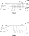
- conventional percutaneous lead 100 includes electrodes 101 that substantially conform to the body of the body portion of the lead. Due to the relatively small profile of percutaneous leads, percutaneous leads are typically positioned above the dura layer through the use of a Touhy-like needle. Specifically, the Touhy-like needle is passed through the skin, between desired vertebrae to open above the dura layer for the insertion of the percutaneous lead.
- conventional laminotomy or paddle lead 150 has a paddle configuration and typically possesses a plurality of electrodes 151 arranged in one or more columns.
- Multi-column laminotomy leads enable reliable positioning of a plurality of electrodes.
- laminotomy leads offer a more stable platform that tends to migrate less after implantation and that is capable of being sutured in place.
- Laminotomy leads also create a uni-directiona! electrical field and, hence, can be used in a more electrically efficient manner than conventional percutaneous leads.
- Due to their dimensions and physical characteristics, conventional laminotomy leads require a surgical procedure for implantation. The surgical procedure (a partial laminectomy) is evasive and requires the resection and removal of certain vertebral tissue to allow both access to the dura and proper positioning of a laminotomy lead.
- US 2009/0326594 discloses a paddle lead with a plurality of electrodes configured in at least three rows of three electrodes with the second, intermediate row operable to provide anode guarding.
- the paddle lead includes a plurality of grooves disposed on a surface opposite the electrodes to transversely flex so as to facilitate insertion of the paddle lead within a patient.
- US 2009/0099439 discloses paddle lead electrodes that are capable of performing peripheral nerve stimulation.
- the paddle lead electrodes are surgically implanted underneath a sheath of protective connective tissue.
- the electrodes include a notch in the ventral surface of the back portion, the notch serves to increase the flexibility of the electrode, thereby allowing the electrode to be bent at the notch to a greater degree than it otherwise would have been able to in order to facilitate placement into the incision.
- WO 2012/170854 which is prior art under Art.54(3) EPC, discloses an implantable paddle lead comprising electrodes on a first surface of a paddle body.
- the implantable paddle lead has regions having a higher pliability extending along a second surface of the paddle body: A first region of increased pliability extends along the paddle body between at least two columns of electrodes, whereas a second region of increased pliability extends along the paddle body between at least two rows of electrodes.
- the present invention is defined in claim 1 with preferred embodiments according to the claims dependent thereon.
- the present disclosure is also directed to the use of a paddle structure to apply electrical stimulation to spinal nervous tissue to treat a variety of diseases and/or conditions, for example pain or chronic pain.
- a stimulation paddle lead is implanted in the patient with electrodes in the epidural space of the patient.
- the paddle portion of the paddle lead is elongated shaped with lengthwise and widthwise scoring on at least one of the front and back faces of the paddle portion.
- Laminotomy lead 200 that can be used for spinal cord stimulation or stimulation of spinal nervous tissue to treat a variety of diseases and/or conditions, for example, but not limited to pain (e.g., peripheral pain), more specifically chronic pain, CRSII or CRSI.
- Laminotomy or paddle lead 200 includes proximal end 210 and distal end 220.
- Proximal end 210 includes a plurality of electrically conductive terminals 212.
- Distal end 220 includes a plurality of electrically conductive electrodes 222 (only 3 of the electrodes have been annotated for the sake of clarity) arranged within a flat, thin, paddle-like structure 230.
- the electrodes 220 are mutually separated by insulative material of the paddle.
- the paddle structure 230 itself may have a width such that it spans the entire dorsal column or fits within the epidural space.
- a paddle structure may be designed to fit into the desired space such that it at least covers the anatomical and physiological midline of the patient.
- the electrodes 222 likewise may have a width such that the combination of the size and number of electrodes span the width of paddle.
- the width of the electrode array can be a width that spans the anatomical and physiological midline.
- the length of the electrodes may vary as well such that the length comprises a length that is appropriate for the length of the paddle structure.
- the paddle structure 230 has a width of about 11mm with the electrodes 222 having an approximate width of about 0.5 mm to about 1.5 mm, or any range there between, more particularly; the width of the electrode can be about 1mm having an approximate electrode array width of about 9mm.
- the spacing of the electrodes 222 may vary as well depending upon the paddle structure and the desired usage or placement of the structure.
- a paddle structure 230 adapted for implantation within a cervical vertebral level good results have been achieved with the electrodes being spaced apart approximately 1.5 mm laterally and 2.5 mm longitudinally.
- a paddle structure 230 adapted for implantation within a thoracic vertebral level good results have been achieved with the electrodes 222 being spaced apart by 1.0 mm laterally and 2 mm to 3 mm longitudinally.
- Conductors 240 (which are embedded within the insulative material of the lead body) electrically connect electrodes 222 to terminals 212.
- Terminals 212 and electrodes 222 are preferably formed of a noncorrosive, highly conductive material. Examples of such material include stainless steel, MP35N, platinum, and platinum alloys. In a preferred embodiment, terminals 212 and electrodes 222 are formed of a platinum-iridium alloy. Each conductor 240 is formed of a conductive material that exhibits desired mechanical properties of low resistance, corrosion resistance, flexibility, and strength. While conventional stranded bundles of stainless steel, MP35N, platinum, platinum-iridium alloy, drawn-brazed silver (DBS) or the like can be used, a preferred embodiment uses conductors 240 formed of multi-strands of drawn-filled tubes (DFT).
- DFT drawn-filled tubes
- Each strand is formed of a low resistance material and is encased in a high strength material (preferably, metal).
- a selected number of "sub-strands" are wound and coated with an insulative material. With regard to the operating environment of representative embodiments, such insulative material protects the individual conductors 240 if its respective sheath 242 was breached during use.
- conductors 240 formed of multi-strands of drawn-filled tubes provide a low resistance alternative to other materials. Specifically, a stranded wire, or even a coiled wire, of approximately 60 cm and formed of MP35N or stainless steel or the like would have a measured resistance in excess of 30 ohms. In contrast, for the same length, a wire formed of multi-strands of drawn-filled tubes could have a resistance less than 4 ohms.
- Sheaths 242 and paddle structure 230 are preferably formed from a medical grade, substantially inert material, for example, polyurethane, silicone, or the like. Importantly, such material should be non-reactive to the environment of the human body, provide a flexible and durable (i.e., fatigue resistant) exterior structure for the components of paddle lead 200, and insulate adjacent terminals 212 and/or electrodes 222. Additional structure (e.g., a nylon mesh, a fiberglass substrate) (not shown) can be internalized within the paddle structure 230 to increase its overall rigidity of the paddle structure 230.
- FIG. 3 depicts paddle lead 200 coupled to IPG 300 which is in wireless communication with programmer device 310.
- IPG 300 An example of a commercially available IPG is the EonTM Rechargeable IPG manufactured by Advanced Neuromodulation Systems, Inc, although any suitable IPG, such as RF powered devices, could be alternatively employed.
- paddle lead 200 is coupled to the headers ports 302 of IPG 300.
- Each header port 302 electrically couples the respective terminals 212 (shown in FIG. 2 ) to a switch matrix (not shown) within IPG 300.
- the switch matrix selectively connects the pulse generating circuitry (not shown) of IPG 300 to the various terminals 212, and, hence to the electrodes 222.
- the sealed portion 304 of IPG 300 contains the pulse generating circuitry, communication circuitry, control circuitry, and battery (not shown) within an enclosure to protect the components after implantation within a patient.
- the control circuitry may comprise a microprocessor, one or more ASICs, and/or any suitable circuitry for controlling the pulse generating circuitry.
- the control circuitry controls the pulse generating circuitry to apply electrical pulses to the patient via electrodes 222 of paddle lead 200 according to multiple pulse parameters (e.g., pulse amplitude, pulse width, pulse frequency, etc.).
- the electrodes 222 are set to function as cathodes or anodes or set to a high-impedance state for a given pulse according to the couplings provided by the switch matrix.
- the electrode states may be changed between pulses.
- a determination of the set(s) of pulse parameters and the electrode configuration(s) that effectively treat the patient's condition is made.
- the determination or programming typically occurs through a physician's interaction with configuration software 312 executed on the programmer device 310.
- Configuration software 312 steps the physician through a number of parameters and electrode configurations.
- the electrode configurations are stepped through by laterally "steering" the electrical field by moving the anodes and/or cathodes along a row of the paddle as discussed above.
- the patient provides feedback to the physician regarding the perceived stimulation that occurs in response the pulse parameters and electrode configuration(s).
- the physician effects changes to the parameters and electrode configuration(s) until optimal pulse parameters and electrode configuration(s) are determined.
- the final pulse parameters and configurations are stored within IPG 300 for subsequent use.
- the pulse parameters and configurations are used by IPG 300 to control the electrical stimulation provided to the patient via paddle lead 200.
- paddle portions 230 with various configurations of scored surfaces on the paddle portion 230.
- the scored surfaces of the present invention are utilized to enhance the flexibility of paddle portion 230 while maintaining a desired amount of rigidity.
- the lengthwise score lines enhance the flexibility of paddle portion 230 about the length of the paddle portion 230, while the widthwise score lines enhance the flexibility of paddle portion 230 about the width of the paddle portion 230.
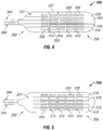
- paddle structure 230 includes an array of electrodes 222 that are spaced apart longitudinally along the length of paddle structure 230 from end 250 towards end 252, and are spaced apart across the width of paddle structure 230. The spacing of the electrodes 222 can be set accordingly to the target implant site and the needed stimulation. Leads 244 are connected to paddle structure 230 and connect thereto in a generally longitudinal alignment with the length of paddle structure 230.
- the front surface or face 231 of paddle structure 230 includes lengthwise or longitudinal score lines 410 that extend between ends 250 and 252 from edge to edge, and further includes widthwise or latitudinal score lines 412 that extend between sides 251 and 253 from edge to edge. Score lines 410 and 412 extend intermediate each of the electrodes 222 to permit flexing of paddle portion 230 and to substantially reduce or eliminate damage to electrodes 222 as a result of the flexing of paddle portion 230.
- the front surface or face 231 of paddle structure 230 includes lengthwise or longitudinal score lines 510 that extend between ends 250 and 252, but do not extend from edge to edge, but rather extend within the perimeter of paddle structure 230.
- Paddle structure 230 further includes widthwise or latitudinal score lines 512 that extend between sides 251 and 253, but do not extend from edge to edge, but rather extend within the perimeter of paddle structure 230.
- the opposing side or face of paddle structure 230 includes an array of electrodes 222 that are spaced apart longitudinally along the length of paddle structure 230 from end 250 towards end 252, and are spaced apart across the width of paddle structure 230.
- the spacing of the electrodes 222 can be set accordingly to the target implant site and the needed stimulation.
- Leads 244 are connected to paddle structure 230 and connect thereto in a generally longitudinal alignment with the length of paddle structure 230.
- Score lines 510 and 512 extend intermediate each of the electrodes 222 to permit flexing of paddle portion 230 and to substantially reduce or eliminate damage to electrodes 222 as a result of the flexing of paddle portion 230.
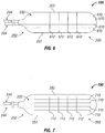
- the back or rear surface 232 of paddle structure 230 includes lengthwise or longitudinal score lines 610 that extend between ends 250 and 252 from edge to edge, and further includes widthwise or latitudinal score lines 712 that extend between sides 251 and 253 from edge to edge.
- the back or rear surface 232 of paddle structure 230 includes lengthwise or longitudinal score lines 710 that extend between ends 250 and 252, but do not extend from edge to edge, but rather extend within the perimeter of paddle structure 230.
- Paddle structure 230 further includes widthwise or latitudinal score lines 712 that extend between sides 251 and 253, but do not extend from edge to edge, but rather extend within the perimeter of paddle structure 230.
- paddle structure 230 includes an array of electrodes 222 that are spaced apart longitudinally along the length of paddle structure 230 from end 250 towards end 252, and are spaced apart across the width of paddle structure 230. The spacing of the electrodes 222 can be set accordingly to the target implant site and the needed stimulation. Leads 244 are connected to paddle structure 230 and connect thereto in a generally longitudinal alignment with the length of paddle structure 230.
- the front surface or face 231 of paddle structure 230 includes lengthwise or longitudinal score lines 810 that extend between ends 250 and 252 from edge to edge.
- the back or rear surface 232 of paddle structure 230 includes widthwise or latitudinal score lines 812 that extend between sides 251 and 253 from edge to edge.
- paddle structure 230 includes an array of electrodes 222 that are spaced apart longitudinally along the length of paddle structure 230 from end 250 towards end 252, and are spaced apart across the width of paddle structure 230. The spacing of the electrodes 222 can be set accordingly to the target implant site and the needed stimulation. Leads 244 are connected to paddle structure 230 and connect thereto in a generally longitudinal alignment with the length of paddle structure 230.
- the front surface or face 231 of paddle structure 230 includes lengthwise or longitudinal score lines 910 that extend between ends 250 and 252, but do not extend from edge to edge, but rather extend within the perimeter of paddle structure 230.
- the back or rear surface 232 of paddle structure 230 includes widthwise or latitudinal score lines 912 that extend between sides 251 and 253, but do not extend from edge to edge, but rather extend within the perimeter of paddle structure 230.
- paddle structure 230 could be implemented with the lengthwise or longitudinal score lines being on the rear surface and the widthwise or latitudinal score lines being or the front surface or face of paddle structure 230, or could be further implemented with various combination of placement score lines on the front and back surfaces of paddle structure 230 depending on the desired amount of flexibility of paddle structure 230.
- paddle structure 230 each of the following can vary depending upon the desired flexibility of the paddle structure 230 as well as the length and width of the paddle structure 230, and further depending upon the number and placement of electrodes: the length of each of the score lines; the number of the score lines; and the lengthwise and widthwise placement of the score lines. It is also contemplated that the score lines need not be of continuous length, rather some or all of the score lines could also be dashed with uniform or varying lengths of dashes.
- paddle portion 230 is implanted within the epidural space, outside the dura matter of the spinal cord with the face or front surface 231 of paddle portion 230 proximate to or facing the dura matter.
- the score lines of paddle portion facilitate the bending or shaping of paddle portion 230 to match the posterior shape of the epidural space.
- The enables the posterior side of the epidural space to assist in containing the paddle portion 230 more evenly fiat against the dura matter. It further enables the face portion 231 to sit more uniformly, both in the longitudinal and latitudinal directions, against the dura matter.
- the score lines facilitate the implantation by being flexible enough to improve the maneuverability of the paddle portion 230, while maintaining enough rigidity to insert the paddle portion into the epidural space of the spinal cord.
Landscapes
- Health & Medical Sciences (AREA)
- Neurology (AREA)
- Neurosurgery (AREA)
- Orthopedic Medicine & Surgery (AREA)
- Cardiology (AREA)
- Heart & Thoracic Surgery (AREA)
- Engineering & Computer Science (AREA)
- Biomedical Technology (AREA)
- Nuclear Medicine, Radiotherapy & Molecular Imaging (AREA)
- Radiology & Medical Imaging (AREA)
- Life Sciences & Earth Sciences (AREA)
- Animal Behavior & Ethology (AREA)
- General Health & Medical Sciences (AREA)
- Public Health (AREA)
- Veterinary Medicine (AREA)
- Electrotherapy Devices (AREA)
Claims (12)
- Medizinisches Elektrodensystem (200) zum Abgeben elektrischer Stimulation an Rückenmarksgewebe eines Patienten, wobei das medizinische Elektrodensystem (200) Folgendes umfasst:einen Elektrodenkörper zum Leiten elektrischer Impulse durch eine Vielzahl von Leitern (240);ein Paddel (230), das dazu konfiguriert ist, innerhalb eines Epiduralraums außerhalb einer Dura mater eines Rückenmarks implantiert zu werden, wobei das Paddel (230) eine Länge und eine Breite aufweist und ferner eine erste Fläche (231) und eine gegenüberliegende zweite Fläche (232) aufweist;eine Vielzahl von Elektroden (222), die in das Paddel (230) integriert ist, wobei ein Abschnitt jeder der Vielzahl von Elektroden (222) an der ersten Fläche (231) des Paddels (230) freiliegt, wobei jede der Vielzahl von Elektroden (222) elektrisch mit jedem der Vielzahl von Leitern (240) verbunden ist, wobei die Vielzahl von Elektroden (222) dazu dient, die elektrischen Impulse von der Vielzahl von Leitern (240) an das Rückenmarksgewebe des Patienten abzugeben; undwobei das Paddel (230) eine Vielzahl von Kerblinien (410, 412; 510, 512; 610, 612; 710; 712; 810, 812; 910, 912) an der zweiten Fläche (232) aufweist, dadurch gekennzeichnet, dass das Paddel (230) die Vielzahl von Kerblinien (410, 412; 510, 512; 610, 612; 710; 712; 810,812; 910, 912) an der ersten Fläche (231) und der zweiten Fläche (232) aufweist, wobei sich eine erste der Vielzahl von Kerblinien (410; 510; 610; 710; 810; 910) an der Länge des Paddels (230) an einer, aber nicht an beiden von der ersten Fläche (231) und der zweiten Fläche (232) entlang erstreckt und sich eine zweite der Vielzahl von Kerblinien (412; 512; 612; 712; 812; 912) entlang der Breite des Paddels (230) an der anderen, aber nicht an beiden von der ersten Fläche (231) und der zweiten Fläche (232) erstreckt, wobei die Vielzahl von Kerblinien (410, 412; 510, 512; 610, 612; 710; 712; 810, 812; 910, 912) eine Flexibilität des Paddels (230) sowohl entlang der Länge als auch der Breite des Paddels (230) ermöglicht.
- Medizinisches Elektrodensystem nach Anspruch 1, wobei sich die erste der Vielzahl von Kerblinien (610; 710), die sich entlang der Länge des Paddels (230) erstreckt, entlang der der Länge des Paddels (230) an der zweiten Fläche (232) des Paddels (230) erstreckt.
- Medizinisches Elektrodensystem nach Anspruch 1, wobei sich die erste der Vielzahl von Kerblinien (410; 510; 810; 910), die sich entlang der Länge des Paddels (230) erstreckt, entlang der Länge des Paddels (230) an der ersten Fläche (231) des Paddels (230) zwischen der Vielzahl von Elektroden (222) erstreckt.
- Medizinisches Elektrodensystem nach Anspruch 1, wobei sich die zweite der Vielzahl von Kerblinien (612; 712; 812; 912), die sich entlang der Breite des Paddels (230) erstreckt, entlang der Breite des Paddels (230) an der zweiten Fläche (232) des Paddels (230) erstreckt.
- Medizinisches Elektrodensystem nach Anspruch 1, wobei sich die zweite der Vielzahl von Kerblinien (412; 512), die sich entlang der Länge des Paddels (230) erstreckt, entlang der Breite des Paddels (230) an der ersten Fläche (231) des Paddels (230) zwischen der Vielzahl von Elektroden (222) erstreckt.
- Medizinisches Elektrodensystem nach Anspruch 1, wobei die Vielzahl von Elektroden (222) in einer Matrix aus Reihen und Spalten angeordnet ist und wobei sich die erste der Vielzahl von Kerblinien (410; 510; 810; 910), die sich entlang der Länge des Paddels (230) erstreckt, entlang der Länge des Paddels (230) an der ersten Fläche (231) des Paddels (230) zwischen einer Spalte der Vielzahl von Elektroden (222) erstreckt.
- Medizinisches Elektrodensystem nach Anspruch 1, wobei die Vielzahl von Elektroden (222) in einer Matrix aus Reihen und Spalten angeordnet ist, und wobei sich die zweite der Vielzahl von Kerblinien (412; 512), die sich entlang der Länge des Paddels (230) erstreckt, entlang der Breite des Paddels (230) an der ersten Fläche (231) des Paddels (230) zwischen einer Reihe der Vielzahl von Elektroden (222) erstreckt.
- Medizinisches Elektrodensystem nach Anspruch 1, wobei die Vielzahl von Elektroden (222) in einer Matrix aus Reihen und Spalten angeordnet ist.
- Medizinisches Elektrodensystem nach Anspruch 8, wobei sich die erste der Vielzahl von Kerblinien (810; 910), die sich entlang der Länge des Paddels (230) erstreckt, entlang der Länge des Paddels (230) an der ersten Fläche (231) des Paddels (230) zwischen einer Spalte der Vielzahl von Elektroden (222) erstreckt, und wobei sich die zweite der Vielzahl von Kerblinien (812; 912), die sich entlang der Breite des Paddels (230) erstreckt, entlang der Breite des Paddels (230) an der zweiten Fläche des Paddels (230) erstreckt.
- Medizinisches Elektrodensystem nach Anspruch 8, wobei sich die erste der Vielzahl von Kerblinien (610; 710), die sich entlang der Länge des Paddels (230) erstreckt, entlang der Länge des Paddels (230) an der zweiten Fläche (232) des Paddel (230) erstreckt, und wobei sich die zweite der Vielzahl von Kerblinien (412; 512), die sich entlang der Breite des Paddels (230) erstreckt, entlang der Breite des Paddels (230) an der ersten Fläche (231) des Paddels (230) zwischen einer Reihe der Vielzahl von Elektroden (222) erstreckt.
- Medizinisches Elektrodensystem nach Anspruch 8, wobei sich die erste der Vielzahl von Kerblinien (810), die sich entlang der Länge des Paddels (230) erstreckt, entlang der Länge des Paddels (230) auf der ersten Fläche (231) des Paddels (230) zwischen einer Spalte der Vielzahl von Elektroden (222) erstreckt, und wobei sich die zweite der Vielzahl von Kerblinien (812), die sich entlang der Breite des Paddels (230) erstreckt, entlang der Breite des Paddels (230) an der zweiten Fläche (232) des Paddels (230) erstreckt und sich über die gesamte Breite des Paddels (230) erstreckt.
- Medizinisches Elektrodensystem nach Anspruch 8, wobei sich die zweite der Vielzahl von Kerblinien (412), die sich entlang der Länge des Paddels (230) erstreckt, entlang der Breite des Paddels (230) an der ersten Fläche (231) des Paddels (230) zwischen einer Reihe der Vielzahl von Elektroden (222) erstreckt und sich über die gesamte Breite des Paddels (230) erstreckt.
Applications Claiming Priority (3)
| Application Number | Priority Date | Filing Date | Title |
|---|---|---|---|
| US201261608380P | 2012-03-08 | 2012-03-08 | |
| US13/789,027 US8903508B2 (en) | 2012-03-08 | 2013-03-07 | Flexible paddle lead body with scored surfaces |
| PCT/US2013/029926 WO2013134664A1 (en) | 2012-03-08 | 2013-03-08 | Flexible paddle lead body with scored surfaces |
Publications (2)
| Publication Number | Publication Date |
|---|---|
| EP2822644A1 EP2822644A1 (de) | 2015-01-14 |
| EP2822644B1 true EP2822644B1 (de) | 2017-02-01 |
Family
ID=49114780
Family Applications (1)
| Application Number | Title | Priority Date | Filing Date |
|---|---|---|---|
| EP13718663.1A Active EP2822644B1 (de) | 2012-03-08 | 2013-03-08 | Flexibler paddelförmiger elektrodenkörper mit gekerbten oberflächen |
Country Status (3)
| Country | Link |
|---|---|
| US (1) | US8903508B2 (de) |
| EP (1) | EP2822644B1 (de) |
| WO (1) | WO2013134664A1 (de) |
Families Citing this family (15)
| Publication number | Priority date | Publication date | Assignee | Title |
|---|---|---|---|---|
| US10492729B2 (en) | 2007-05-23 | 2019-12-03 | St. Jude Medical, Cardiology Division, Inc. | Flexible high-density mapping catheter tips and flexible ablation catheter tips with onboard high-density mapping electrodes |
| US20140200639A1 (en) | 2013-01-16 | 2014-07-17 | Advanced Neuromodulation Systems, Inc. | Self-expanding neurostimulation leads having broad multi-electrode arrays |
| US9440076B2 (en) | 2013-03-15 | 2016-09-13 | Globus Medical, Inc. | Spinal cord stimulator system |
| US10413730B2 (en) | 2013-03-15 | 2019-09-17 | Cirtec Medical Corp. | Implantable pulse generator that generates spinal cord stimulation signals for a human body |
| US10080896B2 (en) | 2013-03-15 | 2018-09-25 | Cirtec Medical Corp. | Implantable pulse generator that generates spinal cord stimulation signals for a human body |
| US10016604B2 (en) | 2013-03-15 | 2018-07-10 | Globus Medical, Inc. | Implantable pulse generator that generates spinal cord stimulation signals for a human body |
| US10226628B2 (en) | 2013-03-15 | 2019-03-12 | Cirtec Medical Corp. | Implantable pulse generator that generates spinal cord stimulation signals for a human body |
| US9643003B2 (en) | 2014-11-10 | 2017-05-09 | Steven Sounyoung Yu | Craniofacial neurostimulation for treatment of pain conditions |
| EP3834759B1 (de) | 2015-10-21 | 2023-04-05 | St. Jude Medical, Cardiology Division, Inc. | Katheter zum hochdichten elektroden-mapping |
| WO2019010399A1 (en) * | 2017-07-06 | 2019-01-10 | Stimdia Medical Inc. | FLEXIBLE ELECTRIC WIRE |
| EP3606420B1 (de) | 2017-07-07 | 2023-05-24 | St. Jude Medical, Cardiology Division, Inc. | Geschichteter hochdichter elektrodenabbildungskatheter |
| US11642063B2 (en) | 2018-08-23 | 2023-05-09 | St. Jude Medical, Cardiology Division, Inc. | Curved high density electrode mapping catheter |
| WO2022031693A1 (en) | 2020-08-03 | 2022-02-10 | Neuroone Medical Technologies Corporation | Methods for making probe devices and related devices |
| US12529607B2 (en) | 2021-07-08 | 2026-01-20 | Neuroone Medical Technologies Corporation | Probe devices with temperature sensors and related systems and methods |
| EP4561666A1 (de) * | 2022-07-25 | 2025-06-04 | Neuroone Medical Technologies Corporation | Verformbare rückenmarkstimulationsvorrichtung sowie zugehörige systeme und verfahren |
Family Cites Families (6)
| Publication number | Priority date | Publication date | Assignee | Title |
|---|---|---|---|---|
| US7359755B2 (en) | 2003-08-08 | 2008-04-15 | Advanced Neuromodulation Systems, Inc. | Method and apparatus for implanting an electrical stimulation lead using a flexible introducer |
| AU2005201649A1 (en) * | 2004-04-19 | 2005-11-03 | Cochlear Limited | Implantable prosthetic device |
| US7603178B2 (en) * | 2005-04-14 | 2009-10-13 | Advanced Neuromodulation Systems, Inc. | Electrical stimulation lead, system, and method |
| US8554337B2 (en) * | 2007-01-25 | 2013-10-08 | Giancarlo Barolat | Electrode paddle for neurostimulation |
| US8214057B2 (en) | 2007-10-16 | 2012-07-03 | Giancarlo Barolat | Surgically implantable electrodes |
| WO2012170854A2 (en) | 2011-06-10 | 2012-12-13 | Boston Scientific Neuromodulation Corporation | Systems and methods for customizing stimulation using implantable electrical stimulation systems |
-
2013
- 2013-03-07 US US13/789,027 patent/US8903508B2/en active Active
- 2013-03-08 WO PCT/US2013/029926 patent/WO2013134664A1/en not_active Ceased
- 2013-03-08 EP EP13718663.1A patent/EP2822644B1/de active Active
Non-Patent Citations (1)
| Title |
|---|
| None * |
Also Published As
| Publication number | Publication date |
|---|---|
| US8903508B2 (en) | 2014-12-02 |
| WO2013134664A1 (en) | 2013-09-12 |
| US20130238077A1 (en) | 2013-09-12 |
| EP2822644A1 (de) | 2015-01-14 |
Similar Documents
| Publication | Publication Date | Title |
|---|---|---|
| EP2822644B1 (de) | Flexibler paddelförmiger elektrodenkörper mit gekerbten oberflächen | |
| US11964148B2 (en) | Implantable lead with flexible paddle electrode array | |
| EP1218057B1 (de) | Leitung zur stimulation der wirbelsäule | |
| US6754539B1 (en) | Spinal cord stimulation lead with an anode guard | |
| US8606367B2 (en) | Insertion tool for paddle-style electrode | |
| US20080228250A1 (en) | Paddle lead comprising opposing diagonal arrangements of electrodes and method for using the same | |
| US6895283B2 (en) | Stimulation/sensing lead adapted for percutaneous insertion | |
| US8706259B2 (en) | Insertion tool for paddle-style electrode | |
| US20120316610A1 (en) | Systems and methods for customizing stimulation using implantable electrical stimulation systems | |
| EP2822643B1 (de) | Paddelführungskörper mit einsatzlasche | |
| US20150224318A1 (en) | Methods and systems for neurostimulation using paddle lead | |
| US10342578B2 (en) | Paddle lead delivery tools |
Legal Events
| Date | Code | Title | Description |
|---|---|---|---|
| PUAI | Public reference made under article 153(3) epc to a published international application that has entered the european phase |
Free format text: ORIGINAL CODE: 0009012 |
|
| 17P | Request for examination filed |
Effective date: 20141008 |
|
| AK | Designated contracting states |
Kind code of ref document: A1 Designated state(s): AL AT BE BG CH CY CZ DE DK EE ES FI FR GB GR HR HU IE IS IT LI LT LU LV MC MK MT NL NO PL PT RO RS SE SI SK SM TR |
|
| AX | Request for extension of the european patent |
Extension state: BA ME |
|
| DAX | Request for extension of the european patent (deleted) | ||
| GRAP | Despatch of communication of intention to grant a patent |
Free format text: ORIGINAL CODE: EPIDOSNIGR1 |
|
| INTG | Intention to grant announced |
Effective date: 20160926 |
|
| GRAS | Grant fee paid |
Free format text: ORIGINAL CODE: EPIDOSNIGR3 |
|
| GRAA | (expected) grant |
Free format text: ORIGINAL CODE: 0009210 |
|
| AK | Designated contracting states |
Kind code of ref document: B1 Designated state(s): AL AT BE BG CH CY CZ DE DK EE ES FI FR GB GR HR HU IE IS IT LI LT LU LV MC MK MT NL NO PL PT RO RS SE SI SK SM TR |
|
| REG | Reference to a national code |
Ref country code: GB Ref legal event code: FG4D |
|
| REG | Reference to a national code |
Ref country code: CH Ref legal event code: EP Ref country code: AT Ref legal event code: REF Ref document number: 865024 Country of ref document: AT Kind code of ref document: T Effective date: 20170215 |
|
| REG | Reference to a national code |
Ref country code: IE Ref legal event code: FG4D |
|
| REG | Reference to a national code |
Ref country code: CH Ref legal event code: NV Representative=s name: E. BLUM AND CO. AG PATENT- UND MARKENANWAELTE , CH |
|
| REG | Reference to a national code |
Ref country code: DE Ref legal event code: R096 Ref document number: 602013017005 Country of ref document: DE |
|
| REG | Reference to a national code |
Ref country code: FR Ref legal event code: PLFP Year of fee payment: 5 |
|
| REG | Reference to a national code |
Ref country code: NL Ref legal event code: MP Effective date: 20170201 |
|
| REG | Reference to a national code |
Ref country code: LT Ref legal event code: MG4D |
|
| REG | Reference to a national code |
Ref country code: AT Ref legal event code: MK05 Ref document number: 865024 Country of ref document: AT Kind code of ref document: T Effective date: 20170201 |
|
| PG25 | Lapsed in a contracting state [announced via postgrant information from national office to epo] |
Ref country code: GR Free format text: LAPSE BECAUSE OF FAILURE TO SUBMIT A TRANSLATION OF THE DESCRIPTION OR TO PAY THE FEE WITHIN THE PRESCRIBED TIME-LIMIT Effective date: 20170502 Ref country code: LT Free format text: LAPSE BECAUSE OF FAILURE TO SUBMIT A TRANSLATION OF THE DESCRIPTION OR TO PAY THE FEE WITHIN THE PRESCRIBED TIME-LIMIT Effective date: 20170201 Ref country code: IS Free format text: LAPSE BECAUSE OF FAILURE TO SUBMIT A TRANSLATION OF THE DESCRIPTION OR TO PAY THE FEE WITHIN THE PRESCRIBED TIME-LIMIT Effective date: 20170601 Ref country code: NO Free format text: LAPSE BECAUSE OF FAILURE TO SUBMIT A TRANSLATION OF THE DESCRIPTION OR TO PAY THE FEE WITHIN THE PRESCRIBED TIME-LIMIT Effective date: 20170501 Ref country code: HR Free format text: LAPSE BECAUSE OF FAILURE TO SUBMIT A TRANSLATION OF THE DESCRIPTION OR TO PAY THE FEE WITHIN THE PRESCRIBED TIME-LIMIT Effective date: 20170201 Ref country code: FI Free format text: LAPSE BECAUSE OF FAILURE TO SUBMIT A TRANSLATION OF THE DESCRIPTION OR TO PAY THE FEE WITHIN THE PRESCRIBED TIME-LIMIT Effective date: 20170201 |
|
| PG25 | Lapsed in a contracting state [announced via postgrant information from national office to epo] |
Ref country code: PL Free format text: LAPSE BECAUSE OF FAILURE TO SUBMIT A TRANSLATION OF THE DESCRIPTION OR TO PAY THE FEE WITHIN THE PRESCRIBED TIME-LIMIT Effective date: 20170201 Ref country code: AT Free format text: LAPSE BECAUSE OF FAILURE TO SUBMIT A TRANSLATION OF THE DESCRIPTION OR TO PAY THE FEE WITHIN THE PRESCRIBED TIME-LIMIT Effective date: 20170201 Ref country code: RS Free format text: LAPSE BECAUSE OF FAILURE TO SUBMIT A TRANSLATION OF THE DESCRIPTION OR TO PAY THE FEE WITHIN THE PRESCRIBED TIME-LIMIT Effective date: 20170201 Ref country code: NL Free format text: LAPSE BECAUSE OF FAILURE TO SUBMIT A TRANSLATION OF THE DESCRIPTION OR TO PAY THE FEE WITHIN THE PRESCRIBED TIME-LIMIT Effective date: 20170201 Ref country code: PT Free format text: LAPSE BECAUSE OF FAILURE TO SUBMIT A TRANSLATION OF THE DESCRIPTION OR TO PAY THE FEE WITHIN THE PRESCRIBED TIME-LIMIT Effective date: 20170601 Ref country code: LV Free format text: LAPSE BECAUSE OF FAILURE TO SUBMIT A TRANSLATION OF THE DESCRIPTION OR TO PAY THE FEE WITHIN THE PRESCRIBED TIME-LIMIT Effective date: 20170201 Ref country code: SE Free format text: LAPSE BECAUSE OF FAILURE TO SUBMIT A TRANSLATION OF THE DESCRIPTION OR TO PAY THE FEE WITHIN THE PRESCRIBED TIME-LIMIT Effective date: 20170201 Ref country code: BG Free format text: LAPSE BECAUSE OF FAILURE TO SUBMIT A TRANSLATION OF THE DESCRIPTION OR TO PAY THE FEE WITHIN THE PRESCRIBED TIME-LIMIT Effective date: 20170501 Ref country code: ES Free format text: LAPSE BECAUSE OF FAILURE TO SUBMIT A TRANSLATION OF THE DESCRIPTION OR TO PAY THE FEE WITHIN THE PRESCRIBED TIME-LIMIT Effective date: 20170201 |
|
| PG25 | Lapsed in a contracting state [announced via postgrant information from national office to epo] |
Ref country code: EE Free format text: LAPSE BECAUSE OF FAILURE TO SUBMIT A TRANSLATION OF THE DESCRIPTION OR TO PAY THE FEE WITHIN THE PRESCRIBED TIME-LIMIT Effective date: 20170201 Ref country code: CZ Free format text: LAPSE BECAUSE OF FAILURE TO SUBMIT A TRANSLATION OF THE DESCRIPTION OR TO PAY THE FEE WITHIN THE PRESCRIBED TIME-LIMIT Effective date: 20170201 Ref country code: RO Free format text: LAPSE BECAUSE OF FAILURE TO SUBMIT A TRANSLATION OF THE DESCRIPTION OR TO PAY THE FEE WITHIN THE PRESCRIBED TIME-LIMIT Effective date: 20170201 Ref country code: SK Free format text: LAPSE BECAUSE OF FAILURE TO SUBMIT A TRANSLATION OF THE DESCRIPTION OR TO PAY THE FEE WITHIN THE PRESCRIBED TIME-LIMIT Effective date: 20170201 |
|
| REG | Reference to a national code |
Ref country code: DE Ref legal event code: R097 Ref document number: 602013017005 Country of ref document: DE |
|
| PG25 | Lapsed in a contracting state [announced via postgrant information from national office to epo] |
Ref country code: MC Free format text: LAPSE BECAUSE OF FAILURE TO SUBMIT A TRANSLATION OF THE DESCRIPTION OR TO PAY THE FEE WITHIN THE PRESCRIBED TIME-LIMIT Effective date: 20170201 Ref country code: SM Free format text: LAPSE BECAUSE OF FAILURE TO SUBMIT A TRANSLATION OF THE DESCRIPTION OR TO PAY THE FEE WITHIN THE PRESCRIBED TIME-LIMIT Effective date: 20170201 Ref country code: DK Free format text: LAPSE BECAUSE OF FAILURE TO SUBMIT A TRANSLATION OF THE DESCRIPTION OR TO PAY THE FEE WITHIN THE PRESCRIBED TIME-LIMIT Effective date: 20170201 |
|
| PLBE | No opposition filed within time limit |
Free format text: ORIGINAL CODE: 0009261 |
|
| STAA | Information on the status of an ep patent application or granted ep patent |
Free format text: STATUS: NO OPPOSITION FILED WITHIN TIME LIMIT |
|
| REG | Reference to a national code |
Ref country code: IE Ref legal event code: MM4A |
|
| 26N | No opposition filed |
Effective date: 20171103 |
|
| GBPC | Gb: european patent ceased through non-payment of renewal fee |
Effective date: 20170501 |
|
| PG25 | Lapsed in a contracting state [announced via postgrant information from national office to epo] |
Ref country code: LU Free format text: LAPSE BECAUSE OF NON-PAYMENT OF DUE FEES Effective date: 20170308 |
|
| PG25 | Lapsed in a contracting state [announced via postgrant information from national office to epo] |
Ref country code: SI Free format text: LAPSE BECAUSE OF FAILURE TO SUBMIT A TRANSLATION OF THE DESCRIPTION OR TO PAY THE FEE WITHIN THE PRESCRIBED TIME-LIMIT Effective date: 20170201 Ref country code: IE Free format text: LAPSE BECAUSE OF NON-PAYMENT OF DUE FEES Effective date: 20170308 |
|
| REG | Reference to a national code |
Ref country code: BE Ref legal event code: MM Effective date: 20170331 |
|
| REG | Reference to a national code |
Ref country code: FR Ref legal event code: PLFP Year of fee payment: 6 |
|
| PG25 | Lapsed in a contracting state [announced via postgrant information from national office to epo] |
Ref country code: GB Free format text: LAPSE BECAUSE OF NON-PAYMENT OF DUE FEES Effective date: 20170501 |
|
| PG25 | Lapsed in a contracting state [announced via postgrant information from national office to epo] |
Ref country code: BE Free format text: LAPSE BECAUSE OF NON-PAYMENT OF DUE FEES Effective date: 20170331 |
|
| PG25 | Lapsed in a contracting state [announced via postgrant information from national office to epo] |
Ref country code: MT Free format text: LAPSE BECAUSE OF NON-PAYMENT OF DUE FEES Effective date: 20170308 |
|
| PG25 | Lapsed in a contracting state [announced via postgrant information from national office to epo] |
Ref country code: HU Free format text: LAPSE BECAUSE OF FAILURE TO SUBMIT A TRANSLATION OF THE DESCRIPTION OR TO PAY THE FEE WITHIN THE PRESCRIBED TIME-LIMIT; INVALID AB INITIO Effective date: 20130308 |
|
| PG25 | Lapsed in a contracting state [announced via postgrant information from national office to epo] |
Ref country code: CY Free format text: LAPSE BECAUSE OF FAILURE TO SUBMIT A TRANSLATION OF THE DESCRIPTION OR TO PAY THE FEE WITHIN THE PRESCRIBED TIME-LIMIT Effective date: 20170201 |
|
| PG25 | Lapsed in a contracting state [announced via postgrant information from national office to epo] |
Ref country code: MK Free format text: LAPSE BECAUSE OF FAILURE TO SUBMIT A TRANSLATION OF THE DESCRIPTION OR TO PAY THE FEE WITHIN THE PRESCRIBED TIME-LIMIT Effective date: 20170201 |
|
| PG25 | Lapsed in a contracting state [announced via postgrant information from national office to epo] |
Ref country code: TR Free format text: LAPSE BECAUSE OF FAILURE TO SUBMIT A TRANSLATION OF THE DESCRIPTION OR TO PAY THE FEE WITHIN THE PRESCRIBED TIME-LIMIT Effective date: 20170201 |
|
| PG25 | Lapsed in a contracting state [announced via postgrant information from national office to epo] |
Ref country code: AL Free format text: LAPSE BECAUSE OF FAILURE TO SUBMIT A TRANSLATION OF THE DESCRIPTION OR TO PAY THE FEE WITHIN THE PRESCRIBED TIME-LIMIT Effective date: 20170201 |
|
| P01 | Opt-out of the competence of the unified patent court (upc) registered |
Effective date: 20230530 |
|
| PGFP | Annual fee paid to national office [announced via postgrant information from national office to epo] |
Ref country code: DE Payment date: 20250210 Year of fee payment: 13 |
|
| PGFP | Annual fee paid to national office [announced via postgrant information from national office to epo] |
Ref country code: FR Payment date: 20250210 Year of fee payment: 13 |
|
| PGFP | Annual fee paid to national office [announced via postgrant information from national office to epo] |
Ref country code: IT Payment date: 20250311 Year of fee payment: 13 |
|
| PGFP | Annual fee paid to national office [announced via postgrant information from national office to epo] |
Ref country code: CH Payment date: 20250401 Year of fee payment: 13 |