EP2822406B1 - Method, metering device and metering valve for the aseptic measured delivery of a liquid additive into a forced flow of a base product - Google Patents
Method, metering device and metering valve for the aseptic measured delivery of a liquid additive into a forced flow of a base product Download PDFInfo
- Publication number
- EP2822406B1 EP2822406B1 EP12712927.8A EP12712927A EP2822406B1 EP 2822406 B1 EP2822406 B1 EP 2822406B1 EP 12712927 A EP12712927 A EP 12712927A EP 2822406 B1 EP2822406 B1 EP 2822406B1
- Authority
- EP
- European Patent Office
- Prior art keywords
- chamber
- metering
- additive
- end section
- terminal part
- Prior art date
- Legal status (The legal status is an assumption and is not a legal conclusion. Google has not performed a legal analysis and makes no representation as to the accuracy of the status listed.)
- Active
Links
- 239000000654 additive Substances 0.000 title claims description 69
- 230000000996 additive effect Effects 0.000 title claims description 64
- 238000000034 method Methods 0.000 title claims description 39
- 239000007788 liquid Substances 0.000 title claims description 11
- 238000007789 sealing Methods 0.000 claims description 37
- 238000002347 injection Methods 0.000 claims description 33
- 239000007924 injection Substances 0.000 claims description 33
- 238000003860 storage Methods 0.000 claims description 28
- 230000001954 sterilising effect Effects 0.000 claims description 26
- 238000004659 sterilization and disinfection Methods 0.000 claims description 24
- 238000001816 cooling Methods 0.000 claims description 13
- 239000012530 fluid Substances 0.000 claims description 12
- 230000035515 penetration Effects 0.000 claims description 10
- 238000003825 pressing Methods 0.000 claims description 8
- 238000011010 flushing procedure Methods 0.000 claims description 7
- 230000009471 action Effects 0.000 claims description 3
- 238000012546 transfer Methods 0.000 claims description 3
- 239000003795 chemical substances by application Substances 0.000 claims 1
- 230000007704 transition Effects 0.000 claims 1
- 238000000605 extraction Methods 0.000 description 15
- 239000000565 sealant Substances 0.000 description 15
- 238000010168 coupling process Methods 0.000 description 8
- 108090000790 Enzymes Proteins 0.000 description 7
- 102000004190 Enzymes Human genes 0.000 description 7
- GUBGYTABKSRVRQ-QKKXKWKRSA-N Lactose Natural products OC[C@H]1O[C@@H](O[C@H]2[C@H](O)[C@@H](O)C(O)O[C@@H]2CO)[C@H](O)[C@@H](O)[C@H]1O GUBGYTABKSRVRQ-QKKXKWKRSA-N 0.000 description 7
- 229940088598 enzyme Drugs 0.000 description 7
- 238000011049 filling Methods 0.000 description 7
- 239000008101 lactose Substances 0.000 description 7
- 230000004888 barrier function Effects 0.000 description 6
- 230000008878 coupling Effects 0.000 description 6
- 238000005859 coupling reaction Methods 0.000 description 6
- 238000004806 packaging method and process Methods 0.000 description 6
- 230000008569 process Effects 0.000 description 6
- 238000005070 sampling Methods 0.000 description 6
- 238000004519 manufacturing process Methods 0.000 description 5
- 230000002572 peristaltic effect Effects 0.000 description 5
- 239000007787 solid Substances 0.000 description 5
- 239000000725 suspension Substances 0.000 description 5
- 238000001514 detection method Methods 0.000 description 4
- 230000002093 peripheral effect Effects 0.000 description 4
- 239000000243 solution Substances 0.000 description 4
- 241000209035 Ilex Species 0.000 description 3
- 244000052616 bacterial pathogen Species 0.000 description 3
- 238000007664 blowing Methods 0.000 description 3
- 238000004140 cleaning Methods 0.000 description 3
- 230000001143 conditioned effect Effects 0.000 description 3
- 238000010438 heat treatment Methods 0.000 description 3
- 230000007062 hydrolysis Effects 0.000 description 3
- 238000006460 hydrolysis reaction Methods 0.000 description 3
- 230000036512 infertility Effects 0.000 description 3
- 238000003466 welding Methods 0.000 description 3
- 241001136792 Alle Species 0.000 description 2
- 241000894006 Bacteria Species 0.000 description 2
- 108010005774 beta-Galactosidase Proteins 0.000 description 2
- 235000013361 beverage Nutrition 0.000 description 2
- 238000003776 cleavage reaction Methods 0.000 description 2
- 239000003086 colorant Substances 0.000 description 2
- 238000010276 construction Methods 0.000 description 2
- 230000001419 dependent effect Effects 0.000 description 2
- 238000006073 displacement reaction Methods 0.000 description 2
- 238000005516 engineering process Methods 0.000 description 2
- 239000005038 ethylene vinyl acetate Substances 0.000 description 2
- 239000000796 flavoring agent Substances 0.000 description 2
- 235000019634 flavors Nutrition 0.000 description 2
- 230000002427 irreversible effect Effects 0.000 description 2
- 150000002632 lipids Chemical class 0.000 description 2
- 230000007246 mechanism Effects 0.000 description 2
- 235000015097 nutrients Nutrition 0.000 description 2
- 239000006041 probiotic Substances 0.000 description 2
- 230000000529 probiotic effect Effects 0.000 description 2
- 235000018291 probiotics Nutrition 0.000 description 2
- 230000007017 scission Effects 0.000 description 2
- 239000008234 soft water Substances 0.000 description 2
- 239000000126 substance Substances 0.000 description 2
- 238000012371 Aseptic Filling Methods 0.000 description 1
- 102100026189 Beta-galactosidase Human genes 0.000 description 1
- 201000008892 GM1 Gangliosidosis Diseases 0.000 description 1
- WQZGKKKJIJFFOK-GASJEMHNSA-N Glucose Natural products OC[C@H]1OC(O)[C@H](O)[C@@H](O)[C@@H]1O WQZGKKKJIJFFOK-GASJEMHNSA-N 0.000 description 1
- 108010059881 Lactase Proteins 0.000 description 1
- 239000002253 acid Substances 0.000 description 1
- 230000006978 adaptation Effects 0.000 description 1
- 230000000712 assembly Effects 0.000 description 1
- 238000000429 assembly Methods 0.000 description 1
- 230000004323 axial length Effects 0.000 description 1
- 238000005452 bending Methods 0.000 description 1
- 230000008901 benefit Effects 0.000 description 1
- WQZGKKKJIJFFOK-FPRJBGLDSA-N beta-D-galactose Chemical compound OC[C@H]1O[C@@H](O)[C@H](O)[C@@H](O)[C@H]1O WQZGKKKJIJFFOK-FPRJBGLDSA-N 0.000 description 1
- WQZGKKKJIJFFOK-VFUOTHLCSA-N beta-D-glucose Chemical compound OC[C@H]1O[C@@H](O)[C@H](O)[C@@H](O)[C@@H]1O WQZGKKKJIJFFOK-VFUOTHLCSA-N 0.000 description 1
- DQXBYHZEEUGOBF-UHFFFAOYSA-N but-3-enoic acid;ethene Chemical compound C=C.OC(=O)CC=C DQXBYHZEEUGOBF-UHFFFAOYSA-N 0.000 description 1
- 239000012459 cleaning agent Substances 0.000 description 1
- 150000001875 compounds Chemical class 0.000 description 1
- 230000006835 compression Effects 0.000 description 1
- 238000007906 compression Methods 0.000 description 1
- 238000011109 contamination Methods 0.000 description 1
- 238000005520 cutting process Methods 0.000 description 1
- 235000013365 dairy product Nutrition 0.000 description 1
- 238000009826 distribution Methods 0.000 description 1
- 230000009977 dual effect Effects 0.000 description 1
- 230000000694 effects Effects 0.000 description 1
- 230000008030 elimination Effects 0.000 description 1
- 238000003379 elimination reaction Methods 0.000 description 1
- 230000007613 environmental effect Effects 0.000 description 1
- 230000002255 enzymatic effect Effects 0.000 description 1
- 235000013305 food Nutrition 0.000 description 1
- 210000001035 gastrointestinal tract Anatomy 0.000 description 1
- 238000003780 insertion Methods 0.000 description 1
- 230000037431 insertion Effects 0.000 description 1
- 238000005304 joining Methods 0.000 description 1
- 229940116108 lactase Drugs 0.000 description 1
- 239000000463 material Substances 0.000 description 1
- 239000012528 membrane Substances 0.000 description 1
- 239000008267 milk Substances 0.000 description 1
- 235000013336 milk Nutrition 0.000 description 1
- 210000004080 milk Anatomy 0.000 description 1
- 230000004048 modification Effects 0.000 description 1
- 238000012986 modification Methods 0.000 description 1
- 235000016709 nutrition Nutrition 0.000 description 1
- 239000004033 plastic Substances 0.000 description 1
- 229920003023 plastic Polymers 0.000 description 1
- 229920001200 poly(ethylene-vinyl acetate) Polymers 0.000 description 1
- 238000012545 processing Methods 0.000 description 1
- 230000005855 radiation Effects 0.000 description 1
- 230000009897 systematic effect Effects 0.000 description 1
- 238000011144 upstream manufacturing Methods 0.000 description 1
- XLYOFNOQVPJJNP-UHFFFAOYSA-N water Substances O XLYOFNOQVPJJNP-UHFFFAOYSA-N 0.000 description 1
Images


Classifications
-
- A—HUMAN NECESSITIES
- A23—FOODS OR FOODSTUFFS; TREATMENT THEREOF, NOT COVERED BY OTHER CLASSES
- A23L—FOODS, FOODSTUFFS, OR NON-ALCOHOLIC BEVERAGES, NOT COVERED BY SUBCLASSES A21D OR A23B-A23J; THEIR PREPARATION OR TREATMENT, e.g. COOKING, MODIFICATION OF NUTRITIVE QUALITIES, PHYSICAL TREATMENT; PRESERVATION OF FOODS OR FOODSTUFFS, IN GENERAL
- A23L3/00—Preservation of foods or foodstuffs, in general, e.g. pasteurising, sterilising, specially adapted for foods or foodstuffs
- A23L3/001—Details of apparatus, e.g. for transport, for loading or unloading manipulation, pressure feed valves
-
- A—HUMAN NECESSITIES
- A23—FOODS OR FOODSTUFFS; TREATMENT THEREOF, NOT COVERED BY OTHER CLASSES
- A23L—FOODS, FOODSTUFFS, OR NON-ALCOHOLIC BEVERAGES, NOT COVERED BY SUBCLASSES A21D OR A23B-A23J; THEIR PREPARATION OR TREATMENT, e.g. COOKING, MODIFICATION OF NUTRITIVE QUALITIES, PHYSICAL TREATMENT; PRESERVATION OF FOODS OR FOODSTUFFS, IN GENERAL
- A23L3/00—Preservation of foods or foodstuffs, in general, e.g. pasteurising, sterilising, specially adapted for foods or foodstuffs
- A23L3/16—Preservation of foods or foodstuffs, in general, e.g. pasteurising, sterilising, specially adapted for foods or foodstuffs by heating loose unpacked materials
- A23L3/18—Preservation of foods or foodstuffs, in general, e.g. pasteurising, sterilising, specially adapted for foods or foodstuffs by heating loose unpacked materials while they are progressively transported through the apparatus
- A23L3/22—Preservation of foods or foodstuffs, in general, e.g. pasteurising, sterilising, specially adapted for foods or foodstuffs by heating loose unpacked materials while they are progressively transported through the apparatus with transport through tubes
-
- A—HUMAN NECESSITIES
- A61—MEDICAL OR VETERINARY SCIENCE; HYGIENE
- A61L—METHODS OR APPARATUS FOR STERILISING MATERIALS OR OBJECTS IN GENERAL; DISINFECTION, STERILISATION OR DEODORISATION OF AIR; CHEMICAL ASPECTS OF BANDAGES, DRESSINGS, ABSORBENT PADS OR SURGICAL ARTICLES; MATERIALS FOR BANDAGES, DRESSINGS, ABSORBENT PADS OR SURGICAL ARTICLES
- A61L2/00—Methods or apparatus for disinfecting or sterilising materials or objects other than foodstuffs or contact lenses; Accessories therefor
- A61L2/02—Methods or apparatus for disinfecting or sterilising materials or objects other than foodstuffs or contact lenses; Accessories therefor using physical phenomena
- A61L2/04—Heat
- A61L2/06—Hot gas
- A61L2/07—Steam
-
- G—PHYSICS
- G01—MEASURING; TESTING
- G01F—MEASURING VOLUME, VOLUME FLOW, MASS FLOW OR LIQUID LEVEL; METERING BY VOLUME
- G01F11/00—Apparatus requiring external operation adapted at each repeated and identical operation to measure and separate a predetermined volume of fluid or fluent solid material from a supply or container, without regard to weight, and to deliver it
- G01F11/28—Apparatus requiring external operation adapted at each repeated and identical operation to measure and separate a predetermined volume of fluid or fluent solid material from a supply or container, without regard to weight, and to deliver it with stationary measuring chambers having constant volume during measurement
- G01F11/30—Apparatus requiring external operation adapted at each repeated and identical operation to measure and separate a predetermined volume of fluid or fluent solid material from a supply or container, without regard to weight, and to deliver it with stationary measuring chambers having constant volume during measurement with supply and discharge valves of the lift or plug-lift type
- G01F11/32—Apparatus requiring external operation adapted at each repeated and identical operation to measure and separate a predetermined volume of fluid or fluent solid material from a supply or container, without regard to weight, and to deliver it with stationary measuring chambers having constant volume during measurement with supply and discharge valves of the lift or plug-lift type for liquid or semiliquid
-
- A—HUMAN NECESSITIES
- A23—FOODS OR FOODSTUFFS; TREATMENT THEREOF, NOT COVERED BY OTHER CLASSES
- A23V—INDEXING SCHEME RELATING TO FOODS, FOODSTUFFS OR NON-ALCOHOLIC BEVERAGES AND LACTIC OR PROPIONIC ACID BACTERIA USED IN FOODSTUFFS OR FOOD PREPARATION
- A23V2002/00—Food compositions, function of food ingredients or processes for food or foodstuffs
Definitions
- the invention relates to a method for the aseptic dosing of a liquid additive, in particular an additive produced and stored under aseptic conditions, in a forced flow of a base product which is also provided under aseptic conditions, wherein the additive under aseptic conditions by means of a withdrawal line from a storage container taken and over an end portion of the extraction line the base product, which flows through a product space, is supplied, and a metering device for carrying out the method and a metering valve for the metering device.
- Liquid aseptic additives of the aforementioned kind such as enzymes, flavors, colors, lipids, probiotic bacteria and other nutrients, are dosed into a foodstuff acting as an aseptic base product of the aforementioned type in order to provide it with special properties. Since these additives can be sensitive to heat, the supply of these additives into the base product takes place immediately before it is filled and after its heat treatment to kill unwanted germs, for example an ultra-high-temperature treatment (UHT heat treatment), and preferably within the framework of a so-called. line dosing.
- UHT heat treatment ultra-high-temperature treatment
- DE10337057 discloses a method for the cold aseptic filling of beverages and US 2002/172745 relates to a system for in-line loading of beverages.
- lactose-reduced or lactose-free products A widespread application, in which an enzyme is used as an additive, is the production of lactose-reduced or lactose-free products.
- lactase is used for the enzymatic cleavage of lactose. consumed These products are mainly used by people who suffer from a deficiency of ⁇ -galactosidase in the digestive tract.
- lactose-reduced milk and related substances is the market for calorie-reduced products. Lactose cleavage produces one molecule each of D-glucose and ⁇ -D-galactose [T ⁇ PEL, 2004, p.
- the dosage rate of the subject enzyme ranges from 0.2 to 4 ml of enzyme / liter of base product (200 to 4000 ppm).
- Tetra FlexDos TM flexible aseptic dosing system for liquid additives
- PD 10080 de 2007-02 a metering device is described with the use of a formed in the form of a flexible bag storage container in which an additive the type in question is stockpiled, an aseptic in-line dosage of this liquid additive is made in a base product.
- the ready-to-use 5 or 10-liter bag filled with the sterile additive under aseptic conditions which in turn is accommodated in a bucket-like outer packaging, is suspended in the metering device.
- hose arrangement acting as a removal arrangement is used to transfer the additive from the bag into the base product, which tube is connected to the bag via a special adapter prior to dosing.
- Hose arrangement and bags are prepared and provided separately from each other, they are usually from different manufacturers and are brought together only in the metering device and firmly connected.
- the hose assembly is arranged an injection needle, via which the additive is metered into the base product at an injection point by means of a hose-wheel pump acting on the hose assembly from the outside.
- the injection point is located on a pipe socket of a pipeline in which the base product flows.
- the injection point is designed as a chamber, which then acts as a sterilizing vapor barrier when it is flowed through by suitable sterile vapor.
- Two in-line membranes, the first between the environment and the interior of the chamber, the second between the interior of the chamber and the interior of the pipeline must be pierced by the injection needle before the dosage can begin.
- the known metering device with the bag used for the purpose and the separate hose assembly have disadvantages particularly in the area of the bag and the coupling of the hose assembly and at the point of injection and cause critical treatment steps that can call into question the absolutely required safety of the sterility of the metering process.
- the extraction port on the bag may be exposed to harmful environmental influences and / or possible faulty actions prior to the coupling of the hose assembly, which may affect the sterility of the critical surfaces leading to the metered additive in the course of the coupling process. A sterilization of these critical surfaces after completion of the coupling process is no longer possible. Since the bag and the hose assembly are separated from one another in each case in an outer packaging, resulting solely by this storage and handling situation, a relatively costly and less user-friendly starting position and a not only theoretical possibility for contamination of the critical surfaces with germs.
- the present invention has in particular the task of dosing aseptic small amounts of an additive up to a maximum of 250 ppm directly into the forced flow of an aseptic base product.
- Advantageous embodiments of the method are described in the subclaims.
- a metering device for carrying out the method is the subject of the dependent claim 11.
- Advantageous embodiments of the metering device are specified in the subclaims.
- a metering valve for the proposed metering device is the subject of the dependent claim 19.
- Advantageous embodiments are specified in the subclaims.
- an end-side part of the end section of the extraction line in whatever form it is designed before it temporarily reaches its metering position and readiness, is at least sterilized under scheduled, reproducible and clearly defined and controlled conditions.
- the end-side part can be an integral part of the end section or a part executed separately from the end section, in the latter case this separate part having a controllable outlet opening, for example in the form of a small metering valve.
- the end-side part of the end portion is still outside the product space in which the dosage takes place, and there are areas of the end-side part of the end portion, in its later dosing at the penetration point within a necessary there sealant and, based on the product space above Be on the side facing away from the product space side of the sealant, included in the sterilization.
- Only after at least this sterilization which is preferably carried out temperature-controlled, reaches the end-side part of the end portion in its metering position, wherein still no connection to the product space is made and this position is referred to as a waiting position.
- the end-side part of the end portion is sealed at its penetration point by means of the previously at least sterilized sealing means.
- the sterilization is carried out in a conventional manner expediently with sterile steam (sterile steam) and the cooling is expediently carried out with sterile air, wherein according to a further proposal, this temperature treatment is carried out in a controlled manner by the sterilization and the cooling carried out temperature-controlled. Only when a predetermined temperature limit value is reached at the temperature measuring point, which, viewed in the flow direction of the respective fluid, is arranged downstream of the end-side part of the extraction line to be treated, is the respective temperature treatment terminated.
- the sterilization is carried out in a targeted manner at a temperature above 125 ° C and the cooling is carried out at a temperature below 50 ° C.
- a rinse of the initial room with sterile condensate (sterile condensate) is carried out below a temperature of 50 ° C.
- This rinsing may be carried out after the treatment step (b) or (c), after the treatment step (c), the initial space is first to be prepared before the rinsing is initiated.
- the additive is metered proportionate to the flowing base product.
- the necessary dosing accuracy is achieved when the transport of the additive in the extraction line and possibly also the removal from the storage container in a conventional manner forcibly done.
- the metering device for carrying out the method according to the invention proceeds in a manner known per se from a metering device with a product line section, which is forcibly flowed through by the base product and which is equipped with at least one storage container for the additive, which in each case connects via the withdrawal line with an associated metering point is.
- a metering device with a product line section, which is forcibly flowed through by the base product and which is equipped with at least one storage container for the additive, which in each case connects via the withdrawal line with an associated metering point is.
- two storage containers are provided, which are operated alternately so as to ensure a continuous metering.
- third means for forcibly conveying the additive first and second means for quantitative detection of the base product and the additive, fourth means for providing sterile steam and a metering device associated control means are provided.
- the solution according to the invention is characterized in that the metering point associated with the respective storage container is provided in each case within a metering valve which, individually, opens the product space into which the product line section enters and exits from the latter, the initial space and the subspace and one Recording the end portion and the end-side part forms.
- An advantageous embodiment of the metering device provides that that part of the initial space which remains after division of the subspace has an inlet and an outlet channel, which can be selectively shut off via an associated shut-off valve and wherein the inlet channel at least with the fourth means for providing of sterile steam is connectable.
- a further treatment of the initial space as part of a flushing, cooling or blow-out is made possible in a simple manner by the feed channel being connectable optionally to a fifth means for providing sterile condensate and / or a sixth means for providing sterile air.
- a check that sterilization or cooling takes place at a sufficient temperature is advantageously and simply ensured by the fact that a temperature sensor is arranged in the drainage channel or downstream immediately after the drainage channel.
- a preferred embodiment of the storage container provides to produce this as a flexible bag of semi-transparent Ethylenvenylazetat (EVA).
- EVA Ethylenvenylazetat
- the sampling line is firmly and tightly connected to the bag.
- This connection can preferably be realized positively and / or non-positively, for example in the form of an elastically ductile coupling, so that a joining of the bag with the extraction line to a tight and tightly connected unit is given in the simplest way. But the connection can also be made cohesively, for example by welding.
- the unit consisting of the filled with the additive bag and the preferably fixed on this withdrawal line in conjunction with the integrated injection needle, the fixed tube with a smooth end or the adapter in a PE outer packaging tightly enclosed and in full to Purpose of the external sterilization of a suitable treatment, for example by a sterilizing radiation, preferably a gamma irradiation exposed.
- a sterilizing radiation preferably a gamma irradiation exposed.
- a kink valve is arranged, with the irreversible breaking a barrier at a predetermined breaking point Fluid borne connection between the interior of the bag and the extraction line is made.
- the connection with the extraction line is made shortly before the start of the dosage, so that the extraction line remains completely free from the additive until this time.
- the end section of the removal line is expedient for the end section of the removal line to be integrally formed as an injection needle with its integral end-side part.
- the end portion with its integral end part also integrally as a tube with a smooth end, which is fixed or ductile deformable, be executed.
- the metering method and the metering device for carrying out the method also make it possible to use an end section in which the end-side part is designed separately from the end section and with a controllable outlet opening, for example in the form of a small metering valve.
- the end portion may in turn be formed as an injection needle or tube with a smooth end that is solid or ductile deformable, or as an adapter for producing a fluidworkingen connection with the end-side part, in which case the end portion is fluidly connected to the end-side part.
- the construction of the metering valve is simplified when the valve housing facing away from the end portion of the housing closure body is formed as a drive piston of the spring-piston drive and penetrated by the first sleeve slidably and sealed, an associated drive housing pot-shaped and penetrated by the first sleeve and with this form - And positively connected, and when the drive spring is supported on the one hand on the drive piston and on the other hand on the first sleeve, preferably on a formed on this spring plate in such a way that the restoring force of the drive spring transfers the closure piston in its closed position.
- a further embodiment provides that the drive housing merges on its side facing away from the drive piston in a cup-shaped, bounded by a union nut clamping housing of the clamping and pressing device, and that the union nut on conical effective surfaces on one of the end portion penetrated forceps acts such that the end portion is fixed axially and radially by the forceps.
- a sufficient and permanent sealing of the first sealing means relative to the end-side part is ensured by the pliers being connected to the one end of a second sleeve received in the first sleeve and completely penetrated by the end portion, and axially acting on the latter such that it engages with the latter the other end of the first sealant axially and radially compressed.
- a metering device 10 for carrying out the method according to the invention ( FIG. 1 ) is usually provided at least twice, with a first metering 10.1 and a second metering 10.2 to ensure a continuous metering, which must be maintained over a longer period of production, side by side in a production line section 12, which is forcibly traversed by an aseptic base product P and for example leads to a filling machine 16, are arranged.
- the metering device 10 is assigned a storage container 18 for an aseptic, liquid additive Z, which is connected via a removal line 18a to a metering point I arranged on or in the product line section 12.
- the first metering device 10.1 is a first storage container 18.1 and a first metering point 1.1 and the second metering device 10.2 a second storage container 18.2 and a second metering I.2 assigned.
- the description is limited to the general structure of a metering device 10, and it is no longer differentiated according to necessarily dual components in two adjacent metering devices 10.1, 10.2.
- a third means 22 is provided for forcibly conveying the additive Z to the metering point I, for example a rotating positive displacement pump, preferably a peristaltic pump.
- the delivery mechanism acts from the outside on the removal line 18a designed in the form of a ductile hose in such a way that there is no direct contact between the delivery mechanism and the additive Z.
- a further possibility for forcibly conveying the additive Z to the metering point I consists, for example, of placing the additive Z in the storage container 18 under overpressure relative to the pressure at the exit point of the removal line 18a at the metering point I.
- This may be pressurization of the storage container 18 from the inside, for example, with sterile air, or even mechanical, hydraulic or pneumatic pressurization from the outside, when the storage container 18 is formed in the form of a ductile deformable bag.
- the removal line 18a is located at the exit point of an end-side part E1 of its end section E (see FIG.
- the end-side part E1 is in this case an integral part of the end section E.
- the end-side part E1 is designed separately from the end section E and with a controllable outlet opening, wherein the end section E in turn as an injection needle 18b or solid or ductile deformable tube with smooth end 18c or as a Adapter 18d may be formed for the production of a fluidloomen connection with the end-side part E1 and the end portion E fluidly connected to the end-side part E1 and connected under aseptic conditions.
- the end-side part E1 may be a small, controllable metering valve which is permanently positioned at the metering point I and optionally temporarily connected to the above-mentioned different configurations 18b, 18c or 18d of the end section E.
- the metering device 10 is equipped with a first means 14 arranged upstream of the metering point I in the product line section 12, for example a mass flow meter, for quantity detection of the base product P flowing there. Furthermore, a second means 20 is provided, with which the amount of the metering point I inflowing additive Z is detected.
- the second means 20 is, for example, a high-precision balance, to which the storage container 18 is attached via a suspension 20a.
- the third means 22, the preferably used peristaltic pump, is connected to a speed control device 36. First and second means 14, 20 and the third means 22 in connection with the speed control device 36 are each connected via signal lines 40, 42 and 44 to a control device 50, so that the additive Z can be metered proportionally proportional to the flowing base product P.
- the metering device 10 furthermore has fourth means 24 for the provision of sterile steam D (sterile steam) for sterilization, whose temperature can be adapted to the sterilization conditions in a manner known per se. If the sterile vapor D is passed through fifth means 24a, for example a heat exchanger acted upon by soft water W, then sterile condensate K (sterile condensate) for flushing can be provided by means of this arrangement in the context of the method according to the invention.
- a sixth means 24b for the provision of sterile air L (sterile air) is provided with which the cooling and the blowing can be accomplished in the context of the inventive method.
- Sterile steam D and sterile condensate K are via a switchable by means of a third shut-off valve 30 first line 24c and the sterile air L is supplied via a second line 24d switchable by means of a fourth shut-off valve 32 to a third line 24e.
- the latter is switchable via a first shut-off valve 26 and connected to a metering valve 100. It sits, seen in the direction of flow of the respective fluid F, the sterile vapor D, sterile condensate K or sterile air L may be behind the metering valve 100 away, there can be connected via a second shut-off valve 28 and opens into a gully 34.
- the temperature of the fluid F flowing downstream of the metering valve 100 in the third line 24e can be measured via a temperature sensor 38, which is connected to the control device 50 via a fourth signal line 46.
- the signals received by the control device 50 are processed there according to the method according to the invention, and control signals for the metering valve 100 are generated therefrom, which are supplied to the latter via a control line 48.
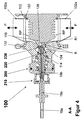
- the metering point I is provided within the metering valve 100 ( FIG. 1 ), wherein the metering valve 100 forms a product space RP into and out of the product line section 12, an initial space R and a subspace R1, and a receptacle of the end portion E and the end portion E1 ( Figures 2 . 1 ).
- That part of the initial space R remaining after the compartment of the subspace R1 has an inflow and outflow channel 104a, 104b ( FIG. 2 ), which can be optionally shut off via the associated shut-off valve 26, 28 and wherein the inlet channel 104a is connectable at least to the fourth means 24 for providing sterile vapor D.
- the inflow channel 104a is optionally connectable to the fifth means 24a for providing sterile condensate K and / or the sixth means 24b for providing sterile air L.
- the temperature sensor 38 is arranged in the drainage channel 104b or downstream immediately after the drainage channel 104b.
- the metering valve 100 is subsequently in the FIGS. 2 to 6 described by way of example in an embodiment in which the end portion E of the sampling line 18a can be accommodated in the form of the injection needle 18b.
- the formed as a ductile bag storage container 18 for the additive Z in conjunction with the injection needle 18 b which are known and introduced in the art for a long time known and introduced in the metering valve 100 according to the invention are used without restriction, without it with regard to bag 18 and Injection needle 18b requires any modification or adaptation to this.
- the metering valve 100 has the product space RP bounded by a valve housing 102, wherein the product line section 12 enters and leaves the valve housing 102 via two pipe stubs 102a, which are preferably formed opposite one another on the valve housing 102 ( Figures 2 . 4 ).
- the valve housing 102 has an unspecified opening, which is sealed by a housing closure body 104 by means of a housing seal 130.
- the housing closure body 104 has an opening 104g to the product space RP (FIG. FIG. 3 ).
- a first sleeve 114 which is arranged coaxially to the passage opening 104g and displaceably engages in a sealed manner from the outside into the housing closure body 104 via a first and a second sleeve seal 136, 138, is driven by means of a spring-piston drive 200 subjected to pressure medium and thus performs a second stroke movement House.
- the valve housing 102 facing away from the end portion of the housing closure body 104 is formed as a drive piston 104f of the spring-piston actuator 200 and penetrated by the first sleeve 114 slidably and sealed.
- An associated drive housing 106 is pot-shaped, forms with the second piston seal 134 outside carrying drive piston 104f one with pressure medium, preferably control air SL ( FIG. 2 ), acted upon drive space 146 and is penetrated by the first sleeve 114 and connected to this positive and non-positive.
- a drive spring 126 of the spring-piston drive 200 is supported, on the one hand, on the drive piston 104f and, on the other hand, on a spring plate 114b formed on the first sleeve 114 in such a way that the restoring force of the drive spring 126 shifts the first sleeve 114 in the direction of the passage opening 104g.
- a space surrounding the drive spring 126 is connected to the surroundings of the metering valve 100 via at least one lantern bore 104c.
- the drive housing 106 is on its side facing away from the drive piston 104 f in a cup-shaped, bounded by a union nut 108 clamping housing 106 a clamping and Anpress worn 210, wherein the union nut 108 via conical effective surfaces on a penetrated by the end portion E forceps 120 a acts such that the end portion E, which in the present case is formed in this region as a shaft 18e of the injection needle 18b, is axially and radially fixed by and against the forceps 120a.
- the pliers 120 a terminate in a connecting part 120, which is connected to a second sleeve 116 arranged in the first sleeve 114.
- the first sleeve 114 is fixed in the bottom of the drive housing 106 between a disc 122, which rests on the ground on the one hand and is fixed by a fixed in the terminal housing 106a first locking ring 124, and a receiving in the first sleeve 114 third retaining ring 148.
- the second sleeve 116 is supported on its end facing away from the connecting part 120 on a also in the first sleeve 114 arranged Andschreibhülse 118 from which form a first sealing device 220 in cooperation with each other.
- the first sealing device 220 is completely penetrated by the end portion E and it seals in cooperation with the clamping and pressing 210 the end portion E1 of the end portion E opposite the first sleeve 114 directly or, as in the present case, indirectly by an axially and radially compressed first Sealant 140 from.
- the axial force necessary for this compression is causally generated by the union nut 108 and transmitted via the forceps 120 a to the second sleeve 116.
- a plunger 110 engages in the valve housing 102 facing away from the passage opening 104g and lies after a first stroke H in its one end position, the closed position, in the peripheral region of the passage opening 104g, which is designed as a first seat surface 104d, with a die seat surface 110b at.
- An actuating rod of the punch 110 and its penetration point through the valve housing 102 are not shown.
- the punch 110 and the penetration point are bridged by a non-designated bellows, preferably a bellows or corrugated tube, cohesively.
- the valve housing 102 is connected on the one hand with the housing closure body 104 and on the other hand with a closure part, not shown, which forms the penetration point and the clamping of the bellows, each via a clamping ring connection 112.
- a space-forming punch recess 110a is provided ( FIG. 3 ), which forms the initial space R together with an in the housing closure body 104 between the passage opening 104g and the front, sliding end of the first sleeve 114 space, wherein the space located in the housing closure body 104 via the inlet and the outlet channel 104a, 104b for the fluid F, which may be sterile vapor D, sterile condensate K or sterile air L, is in each case connected to the environment of the metering valve 100 ( FIG. 2 ).
- the fluid F which may be sterile vapor D, sterile condensate K or sterile air L
- the metering valve 100 further has a closure piston 128, which is penetrated by the end portion E1 of the end portion E and arranged on a first sleeve 114 on the end, in the initial space R projecting into the journal 114a, preferably axially and radially slidably limited limited ,
- the closure piston 128 is in its generated by the restoring force of the drive spring 126 after the second stroke h end position, its closed position, in the peripheral region of the passage opening 104g, which is formed as a second seat 104e, preferably with a first piston seal 132 sealingly.
- the closing piston 128 divides the partial space R1 from the initial space R between itself and the punch recess 110a, and the closing piston 128 is sealed relative to the end-side part E1 by an axially and radially compressed second sealing means 142 in the context of a second sealing device 230.
- the second sealing means 142 has separated from the end-side part E1 by the intrinsic elasticity inherent therein, and all surfaces and regions of the initial space R are subject to the loading accessible with the fluid F.
- the pressing and the widening of the second sealing means 142 are preferably achieved in that the closure piston 128 and the bearing pin 114a engaging in it form a wedge-shaped annular space enclosing the end-side part E1, which tapers from the inside to the outside and receives the second sealing means 142.
- the flanks of the wedge-shaped annular space are so far approximated that the second sealant 142 is axially and radially compressed and thus sealed against the end-side part E1.
- the flanks of the wedge-shaped annular space are so far apart that the second sealing means 142 expands under the action of its inherent elasticity and is far away from the end-side part E1.
- the construction of the metering valve 100 has been described above with reference to FIGS. 2 to 4 Where it is in the so-called. Waiting position, and the FIG. 5 In which it is in the sterilization position described.
- the embedding of the metering valve 100 in the metering device 10 shows FIG. 1 ,
- the waiting position according to the FIGS. 2 to 4 is the drive space 146 not with pressure medium, the control air SL ( FIG. 2 ) .
- the closure piston 128 is pressed under the influence of the restoring force of the drive spring 126 in its sealing closed position on the second seat surface 104e.
- the first and second sealing means 140, 142 seal the injection needle 18b in the manner described above. (From the initial room R FIG.
- the closure piston 128 is moved by acting on the drive chamber 146 with control air SL in its open position.
- the first sealant 140 remains compressed and the second sealant 142 is radially expanded so that the end portion E1 remains permanently positioned and sealed to the first sealant 140 and from there, freely floats into the initial space R of any fluid F.
- fluid F sterile steam D for sterilization, sterile air L for cooling, sterile condensate K for flushing or sterile air L for blowing out can be supplied.
- the product line section 12 is usually scheduled for chemical cleaning, so-called CIP (cleaning in place ), by means of acid and / or lye and rinse water, also a relevant CIP cleaning of all relevant areas of the metering valve 100 can be carried out, wherein the respective cleaning agent via the product line section 12 and is discharged via the drain passage 104b respectively.
- CIP cleaning in place
- the closure piston 128 After sterilization, cooling and, if necessary, rinsing with the subsequent blowing according to FIG. 5 the closure piston 128 is first transferred to the closed position after the elimination of the control air SL under the restoring force of the drive spring 126, the waiting position according to the FIGS. 2 to 4 , The stamp 110 can then be moved to its open position by the first stroke H and the subspace R1 can be opened to the product space RP, in which the base product P flows.
- the metering valve 100 is now in the metering according to FIG. 6 In which the additive Z via the outlet opening of the end portion E1 of the end portion E, in this case the injection needle 18b is in proportion to quantity metered into the flowing product P base.
- a fixed or a ductile deformable tube with a smooth end 18c can also be used analogously in the same way.
- the end part E1 ( FIG. 3 ) of the end section E can also be designed separately from the latter and with a controllable outlet opening. This would then be, for example, a controllable small metering valve.
- the optional coupling of this small metering valve to the end portion E can then, for example, again via an injection needle 18b, a solid or ductile deformable tube with smooth end 18c or an adapter 18d for producing a fluidworkingen connection done, to these conditions, the remaining inventive procedural solution characteristics mutatis mutandis to be transferred.
- the bag 18 and at least the sampling line 18a in the delivery state form a sterile unit and find use in this embodiment in the metering device 10 ( FIG. 1 ).
- the essential features of this unit, its pre- and post-treatment, are briefly described below.
- the bag 18, which preferably has a capacity of, for example, 5 or 10 liters, for the sterile storage of liquid aseptic additives Z, such as enzymes, flavors, colors, lipids, probiotic bacteria and other nutrients, is a flat, rectangular in its unfilled state , Made of a suitable plastic structure, as it is used in its basic form in medical technology application. As a starting form usually a tubular film with a suitable diameter is used, which is a required assembled axial length and then closed at the two open ends by welding, and then on or in these ends, the respective application-specific precautions, peculiarities or requirements are realized. It preferably consists of semi-transparent ethylene vinyl acetate (EVA) with light protection.
- EVA semi-transparent ethylene vinyl acetate
- a so-called. Knick valve arranged with the irreversible breaking a barrier at a predetermined breaking point a fluid possiblye connection between the interior of the bag 18 and the removal arrangement is made.
- the removal arrangement consists of the already described removal line 18 a, preferably a removal hose, the tight and tight with the vorg. Connection is connected. This may be a positive and / or non-positive or even a material connection.
- the extraction line 18a At the end of the extraction line 18a facing away from the coupling, it opens into the described injection needle 18b, with which the additive Z is metered under aseptic conditions into the base product P flowing in the product line section 12. Seen in the direction of flow of the additive Z, the removal arrangement in front of the injection needle 18b preferably has a check valve and a filter in front of it.
- the barrier of the kink valve is broken only after hanging the bag 18 via a preferred three-point suspension in the metering device 10 and shortly before the start of the aseptic dosing at the predetermined breaking point.
- the bag 18 and the attached thereto and fixed thereto removal assembly are sterilized as a unit together with a suitable means. This happens even before the filling of the bag 18 with the additive Z.
- the above-mentioned buckling valve has a constriction and this acts as a predetermined breaking point.
- a sufficient bending moment transverse to the longitudinal axis of the kink valve leads to a complete break of the kink valve at this point, so that the kink valve is separated into two parts.
- the kink valve is inserted into the port with the free end of the first part first, and so on far axially displaced, that after breaking the kink valve at the predetermined breaking point of the isolated, smaller diameter first part passes into the bag 18, so that an unobstructed access from the interior of the bag 18 is ensured by a break in the second part only exposed inner passage to the removal arrangement.
Description
Die Erfindung betrifft ein Verfahren zur aseptischen Dosierung eines flüssigen Zusatzstoffes, insbesondere eines unter aseptischen Bedingungen erzeugten und bevorrateten Zusatzstoffes, in eine erzwungene Strömung eines Basisprodukts, das insbesondere gleichfalls unter aseptischen Bedingungen bereitgestellt wird, wobei der Zusatzstoff unter aseptischen Bedingungen mittels einer Entnahmeleitung aus einem Bevorratungsbehälter entnommen und über einen Endabschnitt der Entnahmeleitung dem Basisprodukt, das einen Produktraum durchströmt, zugeführt wird, sowie eine Dosiereinrichtung zur Durchführung des Verfahrens und ein Dosierventil für die Dosiereinrichtung.The invention relates to a method for the aseptic dosing of a liquid additive, in particular an additive produced and stored under aseptic conditions, in a forced flow of a base product which is also provided under aseptic conditions, wherein the additive under aseptic conditions by means of a withdrawal line from a storage container taken and over an end portion of the extraction line the base product, which flows through a product space, is supplied, and a metering device for carrying out the method and a metering valve for the metering device.
Flüssige aseptische Zusatzstoffe der vorgenannten Art, wie Enzyme, Aromen, Farben, Lipide, probiotische Bakterien und andere Nährstoffe werden in ein als aseptisches Basisprodukt der vorgenannten Art fungierendes Lebensmittel dosiert, um dieses mit besonderen Eigenschaften zu versehen. Da diese Zusatzstoffe hitzeempfindlich sein können, erfolgt die Zuführung dieser Additive in das Basisprodukt direkt vor dessen Abfüllung und nach dessen Wärmebehandlung zur Abtötung unerwünschter Keime, beispielsweise einer Ultra-Hoch-TemperaturBehandlung (UHT-Wärmebehandlung), und vorzugsweise im Rahmen einer sog. In-Line-Dosierung. Die Dosierung muss unter aseptischen Bedingungen und mit einem unter gleichfalls aseptischen Bedingungen bevorrateten sterilen Zusatzstoff erfolgen, damit das im Zuge der Wärmebehandlung aseptisch und damit keimfrei hergestellte Basisprodukt nicht in der Phase der Dosierung mit Keimen infiziert wird.
Ein weitverbreiteter Anwendungsfall, bei dem ein Enzym als Zusatzstoff Verwendung findet, stellt die Herstellung lactosereduzierter oder lactosefreier Produkte dar. Hier wird Lactase zur enzymatischen Spaltung der Lactose eingesetzt. Konsumiert werden diese Produkte vor allem von Menschen, die an einem Mangel an ß-Galactosidase im Verdauungstrakt leiden. Eine weitere Einsatzmöglichkeit für lactosereduzierte Milch und verwandte Substanzen ist der Markt für kalorienreduzierte Produkte. Bei der Lactosespaltung entsteht je ein Molekül D-Glucose und β-D-Galactose [TÖPEL, 2004, S.99; [1] JEKLE;
In der Druckschrift der Firma Tetra Pak Processing GmbH, Tetra FlexDos™, Flexibles aseptisches Dosiersystem für flüssige Zusatzstoffe, PD 10080 de 2007-02, ist eine Dosiereinrichtung beschrieben, mit der unter Verwendung eines in Form eines flexiblen Beutels ausgebildeten Bevorratungsbehälters, in dem ein Zusatzstoff der in Rede stehenden Art bevorratet ist, eine aseptische In-Line-Dosierung dieses flüssigen Zusatzstoffes in ein Basisprodukt vorgenommen wird. Zu diesem Zweck wird der unter aseptischen Bedingungen mit dem sterilen Zusatzstoff gefüllte gebrauchsfertige 5- oder 10-Liter-Beutel, der seinerseits in einer eimerartigen Umverpackung Aufnahme findet, in die Dosiereinrichtung eingehängt. Im Zuge der Dosierung wird zur Überführung des Zusatzstoffes aus dem Beutel in das Basisprodukt eine als Entnahmeanordnung fungierende separate Schlauchanordnung verwendet, die vor der Dosierung über einen speziellen Adapter an den Beutel angeschlossen wird. Schlauchanordnung und Beutel werden getrennt voneinander her- und bereitgestellt, sie stammen im Regelfall von unterschiedlichen Herstellern und werden erst in der Dosiereinrichtung zusammengeführt und miteinander fest verbunden. An dem dem Adapter abgewandten Ende der Schlauchanordnung ist eine Injektionsnadel angeordnet, über die der Zusatzstoff an einem Injektionspunkt mittels einer auf die Schlauchanordnung von außen einwirkenden Schlauchradpumpe in das Basisprodukt eindosiert wird. Der Injektionspunkt befindet sich an einem Rohrstutzen einer Rohrleitung, in der das Basisprodukt strömt. Der Injektionspunkt ist dabei als Kammer ausgebildet, die dann als sterilisierende Dampfbarriere fungiert, wenn sie von geeignetem Sterildampf durchströmt wird. Zwei in Reihe geschaltete Membrane, die erste zwischen der Umgebung und dem Innenraum der Kammer, die zweite zwischen dem Innenraum der Kammer und dem Innenraum der Rohrleitung, müssen von der Injektionsnadel durchstochen werden, bevor die Dosierung beginnen kann.In the document Tetra Pak Processing GmbH, Tetra FlexDos ™, flexible aseptic dosing system for liquid additives, PD 10080 de 2007-02, a metering device is described with the use of a formed in the form of a flexible bag storage container in which an additive the type in question is stockpiled, an aseptic in-line dosage of this liquid additive is made in a base product. For this purpose, the ready-to-use 5 or 10-liter bag filled with the sterile additive under aseptic conditions, which in turn is accommodated in a bucket-like outer packaging, is suspended in the metering device. In the course of dosing, a separate hose arrangement acting as a removal arrangement is used to transfer the additive from the bag into the base product, which tube is connected to the bag via a special adapter prior to dosing. Hose arrangement and bags are prepared and provided separately from each other, they are usually from different manufacturers and are brought together only in the metering device and firmly connected. At the end facing away from the adapter The hose assembly is arranged an injection needle, via which the additive is metered into the base product at an injection point by means of a hose-wheel pump acting on the hose assembly from the outside. The injection point is located on a pipe socket of a pipeline in which the base product flows. The injection point is designed as a chamber, which then acts as a sterilizing vapor barrier when it is flowed through by suitable sterile vapor. Two in-line membranes, the first between the environment and the interior of the chamber, the second between the interior of the chamber and the interior of the pipeline must be pierced by the injection needle before the dosage can begin.
Die bekannte Dosiereinrichtung mit dem zur Anwendung kommenden Beutel und der separaten Schlauchanordnung weisen insbesondere im Bereich des Beutels und der Ankopplung der Schlauchanordnung sowie am Injektionspunkt Nachteile auf und bedingen kritische Behandlungsschritte, die die absolut erforderliche Sicherheit der Sterilität des Dosierprozesses in Frage stellen können.The known metering device with the bag used for the purpose and the separate hose assembly have disadvantages particularly in the area of the bag and the coupling of the hose assembly and at the point of injection and cause critical treatment steps that can call into question the absolutely required safety of the sterility of the metering process.
Der Entnahmeanschluss am Beutel kann vor der Ankopplung der Schlauchanordnung schädlichen Umgebungseinflüssen und/oder möglichen fehlerhaften Handlungen ausgesetzt sein, die die Sterilität der im Zuge des Kopplungsvorganges zusammengeführten, den zu dosierenden Zusatzstoff führenden kritischen Flächen beeinträchtigen können. Eine Sterilisierung dieser kritischen Flächen nach Vollzug des Kopplungsvorganges ist nicht mehr möglich. Da sich der Beutel und die Schlauchanordnung getrennt voneinander jeweils in einer Umverpackung befinden, ergibt sich allein durch diese Aufbewahrungs- und Handhabungssituation eine relativ kostspielige und wenig anwenderfreundliche Ausgangslage sowie eine nicht nur theoretische Möglichkeit zur Kontamination der kritischen Flächen mit Keimen.The extraction port on the bag may be exposed to harmful environmental influences and / or possible faulty actions prior to the coupling of the hose assembly, which may affect the sterility of the critical surfaces leading to the metered additive in the course of the coupling process. A sterilization of these critical surfaces after completion of the coupling process is no longer possible. Since the bag and the hose assembly are separated from one another in each case in an outer packaging, resulting solely by this storage and handling situation, a relatively costly and less user-friendly starting position and a not only theoretical possibility for contamination of the critical surfaces with germs.
Am Injektionspunkt muss darauf vertraut werden, dass während des Ein- und Durchstechvorganges der Injektionsnadel eine hinreichende Sterilisierung dieser stattfindet. Dabei ist weder die Verweilzeit der Injektionsnadel in der Dampfbarriere definiert oder konditioniert noch ist eine Temperaturkontrolle an der bewegten Injektionsnadel möglich. Eine Unterbrechung der Dosierung ist dann mit Blick auf den Zustand der innenseitigen Beaufschlagung der Injektionsnadel mit Zusatzstoff problematisch, wenn diese wegen einer Prozessunterbrechung aus ihrer Dosierposition temporär entfernt und, weil der Beutel mit hochwertigem Zusatzstoff noch teilweise befüllt ist und letzterer noch verbraucht werden soll, bei Fortsetzung der Dosierung erneut in ihre Dosierposition verbracht wird.At the point of injection it must be trusted that sufficient sterilization takes place during the insertion and piercing process of the injection needle. Neither the residence time of the injection needle in the vapor barrier is defined or conditioned, nor is a temperature control on the moving Injection needle possible. An interruption of the dosage is then problematic with regard to the state of the internal loading of the injection needle with additive, if this temporarily removed because of a process interruption from its dosing and, because the bag is still partially filled with high-quality additive and the latter is still to be consumed at Continued dosing is returned to its dosing position.
Sowohl bei der Ankopplung der Schlauchanordnung als auch bei der Sterilisierung der Injektionsnadel herrschen keine planmäßigen, reproduzierbaren und eindeutig konditionierten Bedingungen; zufällige und systematische Fehler können auftreten und die Sicherheit der aseptischen Dosierung in Frage stellen.Both in the coupling of the hose assembly as well as in the sterilization of the injection needle rule no scheduled, reproducible and clearly conditioned conditions; Random and systematic errors can occur and jeopardize the safety of aseptic dosing.
Es ist Zweck der vorliegenden Erfindung, ein Verfahren der gattungsgemäßen Art zu finden und eine Dosiereinrichtung zur Durchführung des Verfahrens sowie ein Dosierventil für die Dosiereinrichtung vorzuschlagen, die die Nachteile des Standes der Technik vermeiden und eine aseptische Dosierung sicherstellen, die durch planmäßige, reproduzierbare und eindeutig konditionierte und kontrollierte Bedingungen gekennzeichnet ist. Die vorliegende Erfindung hat sich insbesondere die Aufgabe gestellt, aseptische Kleinstmengen eines Zusatzstoffes bis maximal 250 ppm direkt in die erzwungene Strömung eines aseptischen Basisprodukts zu dosieren.It is an object of the present invention to find a method of the generic type and to propose a metering device for carrying out the method and a metering valve for the metering device, which avoid the disadvantages of the prior art and ensure aseptic dosing by scheduled, reproducible and unique conditioned and controlled conditions. The present invention has in particular the task of dosing aseptic small amounts of an additive up to a maximum of 250 ppm directly into the forced flow of an aseptic base product.
Der Zweck wird durch ein Verfahren mit den Merkmalen des Anspruchs 1 erfüllt. Vorteilhafte Ausgestaltungen des Verfahrens sind in den Unteransprüchen beschrieben. Eine Dosiereinrichtung zur Durchführung des Verfahrens ist Gegenstand des abhängigen Anspruchs 11. Vorteilhafte Ausführungsformen der Dosiereinrichtung sind in den Unteransprüchen angegeben. Ein Dosierventil für die vorgeschlagene Dosiereinrichtung ist Gegenstand des abhängigen Anspruchs 19. Vorteilhafte Ausführungsformen sind in den Unteransprüchen angegeben.The purpose is fulfilled by a method having the features of claim 1. Advantageous embodiments of the method are described in the subclaims. A metering device for carrying out the method is the subject of the dependent claim 11. Advantageous embodiments of the metering device are specified in the subclaims. A metering valve for the proposed metering device is the subject of the dependent claim 19. Advantageous embodiments are specified in the subclaims.
Der erfinderische Grundgedanke besteht darin, dass ein endseitiger Teil des Endabschnitts der Entnahmeleitung, in welcher Form er auch immer ausgestaltet ist, bevor er temporär in seine Dosierposition und -bereitschaft gelangt, unter planmäßigen, reproduzierbaren und eindeutig definierten und kontrollierten Bedingungen zumindest sterilisiert wird. Bei dem endseitigen Teil kann es sich um einen integralen Teil des Endabschnitts oder um einen separat vom Endabschnitt ausgeführten Teil handeln, wobei im letzten Falle dieser separate Teil mit einer steuerbaren Auslassöffnung, beispielsweise in Gestalt eines kleinen Dosierventils, ausgebildet sein kann. Dabei befindet sich der endseitige Teil des Endabschnitt noch außerhalb des Produktraums, in dem die Dosierung stattfindet, und es werden Bereiche des endseitigen Teils des Endabschnitts, die in seiner späteren Dosierposition an der Durchdringungsstelle innerhalb eines dort notwendigen Dichtungsmittels und, bezogen auf den Produktraum, darüber hinaus auf der vom Produktraum abgewandten Seite des Dichtungsmittels liegen, in die Sterilisierung einbezogen. Erst nach zumindest dieser Sterilisierung, die vorzugsweise temperaturüberwacht erfolgt, gelangt der endseitige Teil des Endabschnitts in seine Dosierposition, wobei noch keine Verbindung zum Produktraum hergestellt ist und diese Position als Warteposition bezeichnet wird. In der Warteposition ist der endseitige Teil des Endabschnitts an seiner Durchdringungsstelle mittels des zuvor zumindest sterilisierten Dichtungsmittels abgedichtet. Nunmehr wird unter diesen eindeutig definierten und kontrollierten Bedingungen eine Verbindung zum Produktraum hergestellt und mit der aseptischen Dosierung begonnen.The inventive idea is that an end-side part of the end section of the extraction line, in whatever form it is designed before it temporarily reaches its metering position and readiness, is at least sterilized under scheduled, reproducible and clearly defined and controlled conditions. The end-side part can be an integral part of the end section or a part executed separately from the end section, in the latter case this separate part having a controllable outlet opening, for example in the form of a small metering valve. In this case, the end-side part of the end portion is still outside the product space in which the dosage takes place, and there are areas of the end-side part of the end portion, in its later dosing at the penetration point within a necessary there sealant and, based on the product space above Be on the side facing away from the product space side of the sealant, included in the sterilization. Only after at least this sterilization, which is preferably carried out temperature-controlled, reaches the end-side part of the end portion in its metering position, wherein still no connection to the product space is made and this position is referred to as a waiting position. In the waiting position, the end-side part of the end portion is sealed at its penetration point by means of the previously at least sterilized sealing means. Now, under these clearly defined and controlled conditions, a connection to the product room is made and the aseptic dosing started.
Die erfindungsgemäße verfahrenstechnische Lösung manifestiert sich durch die folgenden Behandlungsschritte für den Endabschnitt, bevor letzterer den Zusatzstoff dem Basisprodukt zuführt:
- (a) der Endabschnitt wird von einer Seite ein Stück weit in einen anfänglichen Raum temporär eingeführt oder dort permanent positioniert und an der Durchdringungsstelle zu diesem anfänglichen Raum abgedichtet, wobei letzterer wahlweise zum Produktraum hin zu öffnen ist;
- (b) ein in den anfänglichen Raum abgedichtet hineinragender endseitiger Teil des Endabschnitts wird zumindest sterilisiert, wobei alle Bereiche des anfänglichen Raumes gleichfalls in diese Behandlung einbezogen sind;
- (c) der endseitige Teil des Endabschnitts wird in einen von dem anfänglichen Raum wahlweise dicht abteilbaren Teilraum um ein Stück hineinverschoben, wobei der endseitige Teil am Ende der Verschiebung an der Durchdringungsstelle zum Teilraum mittels eines nach Behandlungsschritt (b) behandelten Dichtungsmittels abgedichtet ist;
- (d) der Teilraum wird zum Produktraum hin geöffnet.
- (a) the end portion is temporarily inserted or permanently positioned from one side into an initial space and sealed at the point of penetration to that initial space, the latter being selectively openable to the product space;
- (b) an end portion of the end portion projecting into the initial space is at least sterilized, all portions of the initial space also being included in this treatment;
- (c) the end portion of the end portion is slid one-by-one into a sub-space selectively separable from the initial space, the end portion being sealed at the end of the displacement at the point of penetration to the subspace by means of a sealant treated after treatment step (b);
- (d) the subspace is opened to the product space.
Um zum Einen die Zeitspanne zwischen Sterilisierung und Dosierbeginn zu verkürzen und zum Anderen vor Allem ein Anbrennen des ggf. temperaturempfindlichen Zusatzstoffes im sterilisierten Bereich des Endabschnittes zu verhindern, ist es zweckmäßig, dass sich der Sterilisation nach Behandlungsschritt (b) eine Kühlung unter sterilen Bedingungen anschließt.In order to shorten the period between sterilization and dosing on the one hand and on the other to prevent burning of the possibly temperature-sensitive additive in the sterilized region of the end portion, it is expedient that the sterilization after treatment step (b) followed by cooling under sterile conditions ,
Die Sterilisation erfolgt in an sich bekannter Weise zweckmäßig mit sterilem Dampf (Sterildampf) und die Kühlung erfolgt zweckmäßig mit Sterilluft, wobei gemäß einem weiteren Vorschlag diese Temperaturbehandlung kontrolliert durchgeführt wird, indem die Sterilisation und die Kühlung jeweils temperaturüberwacht erfolgen. Erst wenn an der Temperaturmessstelle, die, in Strömungsrichtung des jeweiligen Fluids gesehen, unterstromig des zu behandelnden endseitigen Teils der Entnahmeleitung angeordnet ist, ein vorgegebener Temperaturgrenzwert erreicht ist, wird die jeweilige Temperaturbehandlung beendet. Dabei wird die Sterilisation in zielführender Weise bei einer Temperatur oberhalb von 125 °C durchgeführt und die Kühlung erfolgt auf eine Temperatur unterhalb 50 °C.The sterilization is carried out in a conventional manner expediently with sterile steam (sterile steam) and the cooling is expediently carried out with sterile air, wherein according to a further proposal, this temperature treatment is carried out in a controlled manner by the sterilization and the cooling carried out temperature-controlled. Only when a predetermined temperature limit value is reached at the temperature measuring point, which, viewed in the flow direction of the respective fluid, is arranged downstream of the end-side part of the extraction line to be treated, is the respective temperature treatment terminated. The sterilization is carried out in a targeted manner at a temperature above 125 ° C and the cooling is carried out at a temperature below 50 ° C.
Um sicherzustellen, dass der Zusatzstoff nicht vorzeitig in den Endabschnitt gelangt, wird im Verlauf des vorgeschlagenen Verfahrens dafür gesorgt, dass die Entnahmeleitung bis zum Vollzug des Behandlungsschrittes (b) oder (c) frei bleibt vom Zusatzstoff und dass erst anschließend der Zusatzstoff bis zur Austrittsstelle des endseitigen Teils verbracht wird.To ensure that the additive does not reach the end prematurely, it is ensured in the course of the proposed method that the extraction line remains free of the additive until the completion of the treatment step (b) or (c) and only then the additive to the exit point the end-side part is spent.
Da nicht auszuschließen ist, dass der Zusatzstoff beim Vorschieben zur Austrittsstelle des endseitigen Teils dort in mehr oder weniger geringen Mengen austritt und dadurch die Dosierung zumindest anfänglich verfälscht werden kann, sieht ein weiterer Vorschlag vor, dass wahlweise eine Spülung des anfänglichen Raumes mit sterilem Kondensat (Sterilkondensat) unterhalb einer Temperatur von 50 °C durchgeführt wird. Diese Spülung kann nach dem Behandlungsschritt (b) oder (c) durchgeführt werden, wobei nach dem Behandlungsschritt (c) zunächst der anfängliche Raum herzustellen ist, bevor die Spülung veranlasst wird. Um den anfänglichen Raum von dem dort nach der Spülung verbleibenden sterilen Kondensat zu befreien, ist es zweckmäßig, dass im Anschluss an die Spülung des anfänglichen Raumes dieser mittels Sterilluft ausgeblasen wird.Since it can not be ruled out that the additive exits in advancing to the exit point of the end-side part there in more or less small amounts and thus the dosage can be at least initially falsified, sees Further proposal that optionally a rinse of the initial room with sterile condensate (sterile condensate) is carried out below a temperature of 50 ° C. This rinsing may be carried out after the treatment step (b) or (c), after the treatment step (c), the initial space is first to be prepared before the rinsing is initiated. In order to free the initial space from the sterile condensate remaining there after flushing, it is expedient that, following the flushing of the initial space, it is blown out by means of sterile air.
Durch messtechnische Vorkehrungen ist sichergestellt, dass der Zusatzstoff mengenproportional zum strömenden Basisprodukt dosiert wird. Die notwendige Dosiergenauigkeit wird erreicht, wenn der Transport des Zusatzstoffes in der Entnahmeleitung und ggf. auch die Entnahme aus dem Bevorratungsbehälter in an sich bekannter Weise zwangsweise erfolgen.By metrological precautions is ensured that the additive is metered proportionate to the flowing base product. The necessary dosing accuracy is achieved when the transport of the additive in the extraction line and possibly also the removal from the storage container in a conventional manner forcibly done.
Die Dosiereinrichtung zur Durchführung des erfindungsgemäßen Verfahrens geht in an sich bekannter Weise aus von einer Dosiereinrichtung mit einem Produktleitungsabschnitt, der von dem Basisprodukt zwangsweise durchströmt ist und die mit wenigstens einem Bevorratungsbehälter für den Zusatzstoff ausgestattet ist, der jeweils über die Entnahmeleitung mit einer zugeordneten Dosierstelle verbunden ist. Im Regelfall sind zwei Bevorratungsbehälter vorgesehen, die im Wechsel betrieben werden, um so eine kontinuierliche Dosierung sicherzustellen. Weiterhin sind dritte Mittel zur zwangsweisen Förderung des Zusatzstoffes, erste und zweite Mitteln zur mengenmäßigen Erfassung des Basisprodukts und des Zusatzstoffes, vierte Mittel zur Bereitstellung von sterilem Dampf und eine der Dosiereinrichtung zugeordnete Steuereinrichtung vorgesehen. Die erfindungsgemäße Lösung ist dadurch gekennzeichnet, dass die dem jeweiligen Bevorratungsbehälter zugeordnete Dosierstelle jeweils innerhalb eines Dosierventils vorgesehen ist, das, jedes für sich, den Produktraum, in den der Produktleitungsabschnitt ein- und aus dem letzterer ausmündet, den anfänglichen Raum und den Teilraum sowie eine Aufnahme des Endabschnitts und des endseitigen Teils ausbildet.The metering device for carrying out the method according to the invention proceeds in a manner known per se from a metering device with a product line section, which is forcibly flowed through by the base product and which is equipped with at least one storage container for the additive, which in each case connects via the withdrawal line with an associated metering point is. As a rule, two storage containers are provided, which are operated alternately so as to ensure a continuous metering. Furthermore, third means for forcibly conveying the additive, first and second means for quantitative detection of the base product and the additive, fourth means for providing sterile steam and a metering device associated control means are provided. The solution according to the invention is characterized in that the metering point associated with the respective storage container is provided in each case within a metering valve which, individually, opens the product space into which the product line section enters and exits from the latter, the initial space and the subspace and one Recording the end portion and the end-side part forms.
Eine vorteilhafte Ausführungsform der Dosiereinrichtung sieht vor, dass jener Teil des anfänglichen Raumes, der nach Abteilung des Teilraumes verbleibt, einen Zulauf- und einen Ablaufkanal aufweist, die wahlweise jeweils über ein zugeordnetes Absperrventil absperrbar sind und wobei der Zulaufkanal wenigstens mit dem vierten Mittel zur Bereitstellung von sterilem Dampf verbindbar ist. Eine weitergehende Behandlung des anfänglichen Raumes im Rahmen einer Spülung, Kühlung oder eines Ausblasens wird auf einfache Weise dadurch möglich, dass der Zulaufkanal wahlweise mit einem fünften Mittel zur Bereitstellung von sterilem Kondensat und/oder einem sechsten Mittel zur Bereitstellung von Sterilluft verbindbar ist.An advantageous embodiment of the metering device provides that that part of the initial space which remains after division of the subspace has an inlet and an outlet channel, which can be selectively shut off via an associated shut-off valve and wherein the inlet channel at least with the fourth means for providing of sterile steam is connectable. A further treatment of the initial space as part of a flushing, cooling or blow-out is made possible in a simple manner by the feed channel being connectable optionally to a fifth means for providing sterile condensate and / or a sixth means for providing sterile air.
Eine Kontrolle, dass Sterilisation auf oder Kühlung unter eine hinreichende Temperatur erfolgt, wird zweckmäßig und einfach dadurch sichergestellt, dass im Ablaufkanal oder unterstromig unmittelbar im Anschluss an den Ablaufkanal ein Temperaturfühler angeordnet ist.A check that sterilization or cooling takes place at a sufficient temperature is advantageously and simply ensured by the fact that a temperature sensor is arranged in the drainage channel or downstream immediately after the drainage channel.
Höhere aseptische Sicherheit wird gegenüber dem bekannt gewordenen Stand der Technik dadurch erreicht, dass der Bevorratungsbehälter und wenigstens die Entnahmeleitung im Anlieferungszustand eine sterile Einheit bilden. Eine bevorzugte Ausführungsform des Bevorratungsbehälters sieht vor, diesen als flexiblen Beutel aus halbtransparentem Ethylenvenylazetat (EVA) herzustellen. Vor der Befüllung des Beutels mit dem Zusatzstoff ist die Entnahmeleitung mit dem Beutel fest und dicht verbunden. Diese Verbindung kann vorzugsweise form- und/oder kraftschlüssig verwirklicht sein, beispielsweise in Form einer elastisch duktilen Kupplung, sodass ein Fügen des Beutels mit der Entnahmeleitung zu einer fest und dicht verbundenen Einheit auf einfachste Weise gegeben ist. Die Verbindung kann aber auch stoffschlüssig ausgeführt werden, beispielsweise durch Verschweißung. In jedem Falle kann die Einheit, bestehend aus dem mit dem Zusatzstoff befüllten Beutel und der auf diesem vorzugsweise fixierten Entnahmeleitung in Verbindung mit der integrierten Injektionsnadel, dem festen Rohr mit glattem Ende oder dem Adapter, in einer PE-Umverpackung dicht eingeschlossen und in Gänze zum Zwecke der äußerlichen Sterilisierung einer geeigneten Behandlung, beispielsweise durch eine sterilisierende Bestrahlung, vorzugsweise einer Gammabestrahlung, ausgesetzt werden. Diese erfindungsgemäße Lösung beseitigt sicher die ansonsten bestehende Möglichkeit der Beeinträchtigung der Sterilität der Verbindung, wenn letztere erst nach der Befüllung des Beutels mit dem Zusatzstoff und vor der Dosierung des aseptischen Zusatzstoffes in das aseptische Basisprodukt hergestellt wird.Higher aseptic safety is achieved compared with the prior art that has become known in that the storage container and at least the withdrawal conduit in the delivery state form a sterile unit. A preferred embodiment of the storage container provides to produce this as a flexible bag of semi-transparent Ethylenvenylazetat (EVA). Before filling the bag with the additive, the sampling line is firmly and tightly connected to the bag. This connection can preferably be realized positively and / or non-positively, for example in the form of an elastically ductile coupling, so that a joining of the bag with the extraction line to a tight and tightly connected unit is given in the simplest way. But the connection can also be made cohesively, for example by welding. In any case, the unit, consisting of the filled with the additive bag and the preferably fixed on this withdrawal line in conjunction with the integrated injection needle, the fixed tube with a smooth end or the adapter in a PE outer packaging tightly enclosed and in full to Purpose of the external sterilization of a suitable treatment, for example by a sterilizing radiation, preferably a gamma irradiation exposed. This solution according to the invention is eliminated certainly the otherwise existing possibility of impairing the sterility of the compound, if the latter is produced only after the filling of the bag with the additive and before the dosage of the aseptic additive in the aseptic base product.
Um auch im Bereich eines Anschlusses des Beutels an die Entnahmeleitung nach der Befüllung des Beutels mit dem Zusatzstoff nachhaltig sterile Bedingungen herzustellen, sieht eine weitere Ausführungsform vor, dass in diesem Anschluss ein Knickventil angeordnet ist, mit dem durch irreversibles Brechen einer Barriere an einer Sollbruchstelle eine fluidgängige Verbindung zwischen dem Innenraum des Beutels und der Entnahmeleitung hergestellt wird. Die Verbindung mit der Entnahmeleitung wird erst kurz vor der Inbetriebnahme der Dosierung hergestellt, sodass die Entnahmeleitung bis zu diesem Zeitpunkt vollständig frei vom Zusatzstoff bleibt.In order to produce sustainable sterile conditions even in the region of a connection of the bag to the sampling line after the filling of the bag with the additive, provides a further embodiment that in this connection a kink valve is arranged, with the irreversible breaking a barrier at a predetermined breaking point Fluidgängige connection between the interior of the bag and the extraction line is made. The connection with the extraction line is made shortly before the start of the dosage, so that the extraction line remains completely free from the additive until this time.
Damit eine derartige Anordnung nicht nur in der erfindungsgemäßen, sondern auch in bekannten Dosiereinrichtungen Verwendung finden kann, ist es zielführend, dass der Endabschnitt der Entnahmeleitung mit seinem integralen endseitigen Teil einstückig als Injektionsnadel ausgebildet ist. In anderen Fällen, in denen die Entnahmeleitung nicht über eine Injektionsnadel in die Dosierstelle einmündet, sondern nach Maßgabe des vorgeschlagenen Dosierverfahrens innerhalb des erfindungsgemäßen Dosierventils einen Anschluss findet, kann der Endabschnitt mit seinem integralen endseitigen Teil auch einstückig als Rohr mit glattem Ende, das fest ist oder duktil verformbar ist, ausgeführt sein.In order for such an arrangement to be used not only in the metering devices according to the invention but also in known metering devices, it is expedient for the end section of the removal line to be integrally formed as an injection needle with its integral end-side part. In other cases in which the sampling line does not open via an injection needle in the metering, but according to the proposed dosing within the metering valve according to the invention finds a connection, the end portion with its integral end part also integrally as a tube with a smooth end, which is fixed or ductile deformable, be executed.
Das Dosierverfahren und die Dosiereinrichtung zur Durchführung des Verfahrens ermöglichen aber auch die Verwendung eines Endabschnitts, bei dem der endseitige Teil separat vom Endabschnitt und mit einer steuerbaren Auslassöffnung, beispielsweise in Gestalt eines kleinen Dosierventils, ausgeführt ist. In diesem Falle kann der Endabschnitt wiederum als Injektionsnadel oder Rohr mit glattem Ende, das fest oder duktil verformbar ist, oder als Adapter zur Herstellung einer fluidgängigen Verbindung mit dem endseitigen Teil ausgebildet sein, wobei dann der Endabschnitt mit dem endseitigen Teil fluidgängig verbunden ist.However, the metering method and the metering device for carrying out the method also make it possible to use an end section in which the end-side part is designed separately from the end section and with a controllable outlet opening, for example in the form of a small metering valve. In this case, the end portion may in turn be formed as an injection needle or tube with a smooth end that is solid or ductile deformable, or as an adapter for producing a fluidgängigen connection with the end-side part, in which case the end portion is fluidly connected to the end-side part.
Ein erfindungsgemäßes Dosierventil für die Dosiereinrichtung ist u.a. durch folgende Baugruppen gekennzeichnet:
- einer ersten und einer zweiten Abdichteinrichtung für den endseitigen Teil der Entnahmeleitung;
- einer ersten Hülse, die den endseitigen Teil der Entnahmeleitung und die Entnahmeleitung aufnimmt und die durch einen Feder-Kolben-Antrieb mit einer zweiten Hubbewegung axial verschieblich angetrieben ist;
- einer Klemm- und Anpresseinrichtung, die mit dem Feder-Kolben-Antrieb axial verschieblich bewegt wird, die Entnahmeleitung axial und radial festlegt und die für den Anpressdruck in der ersten Abdichteinrichtung zur Erzeugung einer hinreichenden Dichtwirkung in einem ersten Dichtungsmittel an der Durchdringungsstelle des endseitigen Teils zum anfänglichen Raum sorgt.
- a first and a second sealing device for the end-side part of the extraction line;
- a first sleeve which receives the end portion of the extraction line and the extraction line and which is axially displaceably driven by a spring-piston drive with a second stroke movement;
- a clamping and pressing device which is moved axially displaceably with the spring-piston drive, the extraction line axially and radially sets and the pressure for the first in the first sealing device to produce a sufficient sealing effect in a first sealing means at the penetration point of the end-side part provides initial space.
Neben diesen Baugruppen weist das Dosierventil folgende Merkmale auf:
- ein in dem Produktleitungsabschnitt angeordnetes, den Produktraum berandendes Ventilgehäuse;
- einen das Ventilgehäuse einerseits verschließenden Gehäuseverschlusskörper mit einer Durchtrittsöffnung zum Produktraum;
- einen Stempel, der von der der Durchtrittsöffnung abgewandten Seite des Ventilgehäuses in dieses eingreift und nach einer ersten Hubbewegung in seiner einen Endlage, der Schließstellung, im Umfangsbereich der Durchtrittsöffnung, der als erste Sitzfläche ausgebildet ist, mit einer Stempelsitzfläche anliegt,
- eine in der der Durchtrittsöffnung zugewandten Stirnfläche des Stempels vorgesehene raumbildende Stempelausnehmung, die zusammen mit einem in dem Gehäuseverschlusskörper zwischen der Durchtrittsöffnung und dem stirnseitigen, verschieblichen Ende der ersten Hülse befindlichen Raum den anfänglichen Raum ausbildet, wobei der im Gehäuseverschlusskörper befindliche Raum über einen Zulauf- und einen Ablaufkanal jeweils mit der Umgebung des Dosierventils verbunden ist;
- einen Verschlusskolben, der von dem endseitigen Teil des Endabschnittes durchdrungen und auf einem an der ersten Hülse endseitig angeordneten, in den anfänglichen Raum hineinragenden Lagerzapfen angeordnet ist.
- a valve housing disposed in the product conduit section and surrounding the product space;
- a housing closure body which closes the valve housing on the one hand and has a passage opening to the product space;
- a punch, which engages the side facing away from the passage opening of the valve housing in this and rests after a first stroke in its one end position, the closed position, in the peripheral region of the passage opening, which is designed as a first seat, with a punch seat surface,
- a in the passage opening facing end face of the punch provided space-forming punch recess, which forms the initial space together with a in the housing closure body between the passage opening and the front, sliding end of the first sleeve space, the space located in the housing closure body via an inlet and a drain passage is connected to each of the surroundings of the metering valve;
- a closure piston, which is penetrated by the end-side part of the end portion and arranged on an end side of the first sleeve, projecting into the initial space bearing pin.
Besondere Bedeutung kommt im Rahmen der Erfindung dem Verschlusskolben in seinen durch die zweite Hubbewegung bestimmten Endlagen, einer Schließ- und einer Offenstellung, mit Blick auf die in ihm vorgesehene, auf ein zweites Dichtungsmittel einwirkende zweite Abdichteinrichtung zu:
- der Verschlusskolben liegt in seiner durch eine Antriebsfeder im Feder-KolbenAntrieb nach der zweiten Hubbewegung erzeugten Endlage, der Schließstellung, im Umfangsbereich der Durchtrittsöffnung, der als zweite Sitzfläche ausgebildet ist, dichtend an, wobei der Verschlusskolben in seiner Schließstellung zwischen sich und der Stempelausnehmung den Teilraum von dem anfänglichen Raum abteilt und der Verschlusskolben gegenüber dem endseitigen Teil durch das axial und radial verpresste zweite Dichtungsmittel abgedichtet ist;
- in einer mit der zweiten Hubbewegung erzeugten anderen Endlage des Verschlusskolbens, der Offenstellung, hat sich das zweite Dichtungsmittel spaltweit von dem endseitigen Teil gelöst und alle Oberflächen und Bereiche des anfänglichen Raumes sind der Beaufschlagung mit einem Fluid, dem sterilen Dampf, dem sterilen Kondensat oder der Sterilluft, zugänglich.
- the closure piston is sealingly in its generated by a drive spring in the spring-piston drive after the second stroke end position, the closed position, in the peripheral region of the passage opening, which is designed as a second seat, the closure piston in its closed position between it and the punch recess the subspace separates from the initial space and the closure piston is sealed against the end-side part by the axially and radially compressed second sealant;
- In a second end position of the closure piston, the open position, which is produced with the second lifting movement, the second sealing means has been detached from the end-side part and all surfaces and areas of the initial space are exposed to a fluid, the sterile steam, the sterile condensate or the Sterile air, accessible.
Die Konstruktion des Dosierventils wird vereinfacht, wenn der dem Ventilgehäuse abgewandte Endabschnitt des Gehäuseverschlusskörpers als Antriebskolben des Feder-Kolben-Antriebs ausgebildet und von der ersten Hülse verschieblich und abgedichtet durchdrungen ist, ein zugeordnetes Antriebsgehäuse topfartig ausgebildet und von der ersten Hülse durchdrungen und mit dieser form- und kraftschlüssig verbunden ist, und wenn sich die Antriebsfeder einerseits am Antriebskolben und andererseits an der ersten Hülse, vorzugsweise an einem an dieser ausgebildeten Federteller, in der Weise abstützt, dass die Rückstellkraft der Antriebsfeder den Verschlusskolben in seine Schließstellung überführt.The construction of the metering valve is simplified when the valve housing facing away from the end portion of the housing closure body is formed as a drive piston of the spring-piston drive and penetrated by the first sleeve slidably and sealed, an associated drive housing pot-shaped and penetrated by the first sleeve and with this form - And positively connected, and when the drive spring is supported on the one hand on the drive piston and on the other hand on the first sleeve, preferably on a formed on this spring plate in such a way that the restoring force of the drive spring transfers the closure piston in its closed position.
Eine weitere Ausführungsform sieht vor, dass das Antriebsgehäuse auf seiner dem Antriebskolben abgewandten Seite in ein topfförmiges, durch eine Überwurfmutter begrenztes Klemmgehäuse der Klemm- und Anpresseinrichtung übergeht, und dass die Überwurfmutter über konische Wirkflächen auf eine von dem Endabschnitt durchdrungene Zange dergestalt einwirkt, dass der Endabschnitt durch die Zange axial und radial festgelegt ist.A further embodiment provides that the drive housing merges on its side facing away from the drive piston in a cup-shaped, bounded by a union nut clamping housing of the clamping and pressing device, and that the union nut on conical effective surfaces on one of the end portion penetrated forceps acts such that the end portion is fixed axially and radially by the forceps.
Eine hinreichende und dauerhafte Abdichtung des ersten Dichtungsmittels gegenüber dem endseitigen Teil wird dadurch sichergestellt, dass die Zange mit dem einen Ende einer in der ersten Hülse aufgenommenen, von dem Endabschnitt vollständig durchdrungenen zweiten Hülse verbunden ist und axial derart auf letztere einwirkt, dass diese mit ihrem anderen Ende das erste Dichtungsmittel axial und radial verpresst.A sufficient and permanent sealing of the first sealing means relative to the end-side part is ensured by the pliers being connected to the one end of a second sleeve received in the first sleeve and completely penetrated by the end portion, and axially acting on the latter such that it engages with the latter the other end of the first sealant axially and radially compressed.
Eine hinreichende und dauerhafte Abdichtung des im Verschlusskolben angeordneten zweiten Dichtungsmittels gegenüber dem endseitigen Teil wird dadurch sichergestellt, dass der Verschlusskolben und der in diesen eingreifende Lagerzapfen einen den endseitigen Teil umschließenden keilförmigen Ringraum bilden, der sich von innen nach außen verjüngt und das zweite Dichtungsmittel aufnimmt. In der Schließstellung des Verschlusskolbens sind die Flanken des keilförmigen Ringraumes so weit angenähert, dass das zweite Dichtungsmittel axial und radial verpresst und damit gegen den endseitigen Teil abgedichtet ist. In der Offenstellung des Verschlusskolbens sind die Flanken des keilförmigen Ringraumes so weit voneinander entfernt, dass sich das zweite Dichtungsmittel aufweitet und spaltweit von dem endseitigen Teil entfernt ist.Sufficient and permanent sealing of the second sealing means arranged in the closure piston relative to the end-side part is ensured by the closure piston and the bearing pin engaging in the latter forming a wedge-shaped annular space enclosing the end part, which tapers from the inside to the outside and absorbs the second sealing means. In the closed position of the closure piston, the flanks of the wedge-shaped annular space are so far approximated that the second sealant is axially and radially compressed and thus sealed against the end-side part. In the open position of the closure piston, the flanks of the wedge-shaped annular space are so far apart that the second sealing means expands and is far away from the end-side part.
Eine eingehendere Darstellung der Erfindung ergibt sich aus der folgenden Beschreibung und den beigefügten Figuren der Zeichnung sowie aus den Ansprüchen. Während die Erfindung in den verschiedensten Ausgestaltungen eines Verfahrens, einer Dosiereinrichtung und eines Dosierventils realisiert ist, werden in der Zeichnung ein Verfahren, eine Dosiereinrichtung und ein Dosierventil jeweils in einer bevorzugten Ausführungsform beschrieben. Es zeigen
- Figur 1
- in sehr vereinfachter schematischer Darstellung eine Dosiereinrichtung zur Durchführung des erfindungsgemäßen Verfahrens, wobei lediglich eine einzige Dosiereinrichtung dargestellt ist, während im Regelfall mindestens zwei Dosiereinrichtungen im Wechsel betrieben werden;
- Figur 2
- in perspektivischer Darstellung ein in seiner Meridianebene aufgeschnittenes Dosierventil für die Dosiereinrichtung gemäß
Figur 1 ; wobei die Meridianebene senkrecht zur Strömungsrichtung des in einem Produktleitungsabschnitt strömenden aseptischen Basisprodukts, in das ein aseptischer Zusatzstoff dosiert wird, orientiert ist und das Dosierventil sich in seiner Warteposition befindet; - Figur 3
- in einer Schnittdarstellung das in der Meridianebene gemäß
Figur 2 aufgeschnittene Dosierventil in einer dort mit "B" gekennzeichneten Blickrichtung; - Figur 4
- in einer Schnittdarstellung das Dosierventil gemäß
Figur 2 in einer weiteren Meridianebene, wobei der zugehörige Schnittverlauf inFigur 3 mit A-A gekennzeichnet ist; - Figur 5
- die Schnittdarstellung des Dosierventils gemäß
Figur 3 , wobei sich dieses nunmehr in seiner Sterilisationsposition befindet und - Figur 6
- die Schnittdarstellung des Dosierventils gemäß
Figur 3 , wobei sich dieses nunmehr in seiner Dosierposition befindet.
- FIG. 1
- in a very simplified schematic representation of a metering device for carrying out the method according to the invention, wherein only a single metering device is shown while As a rule, at least two metering devices are operated alternately;
- FIG. 2
- in perspective view a cut in his meridian plane metering valve for the metering device according to
FIG. 1 ; wherein the meridional plane is oriented perpendicular to the flow direction of the aseptic base product flowing in a product line section, into which an aseptic additive is metered, and the metering valve is in its waiting position; - FIG. 3
- in a sectional view according to the meridian plane
FIG. 2 cut metering valve in a direction marked there with "B" viewing direction; - FIG. 4
- in a sectional view of the metering valve according to
FIG. 2 in a further Meridianebene, whereby the appropriate cutting course inFIG. 3 marked with AA ; - FIG. 5
- the sectional view of the metering valve according to
FIG. 3 , this is now in its sterilization position and - FIG. 6
- the sectional view of the metering valve according to
FIG. 3 , this is now in its dosing position.
Eine Dosiereinrichtung 10 zur Durchführung des erfindungsgemäßen Verfahrens (
In der Entnahmeleitung 18a ist ein drittes Mittel 22 zur zwangsweisen Förderung des Zusatzstoffes Z an die Dosierstelle I vorgesehen, beispielsweise eine rotierende Verdrängerpumpe, vorzugsweise eine Schlauchradpumpe. Bei einer Schlauchradpumpe wirkt der Fördermechanismus von außen auf die in Gestalt eines duktil verformbaren Schlauches ausgebildete Entnahmeleitung 18a in der Weise ein, dass keine unmittelbarer Kontakt zwischen dem Fördermechanismus und dem Zusatzstoff Z gegeben ist.In the
Eine weitere Möglichkeit, den Zusatzstoff Z zwangsweise an die Dosierstelle I zu fördern, besteht beispielsweise darin, den Zusatzstoff Z im Bevorratungsbehälter 18 unter Überdruck gegenüber dem Druck an der Austrittsstelle der Entnahmeleitung 18a an der Dosierstelle I zu setzen. Hierbei kann es sich um Druckbeaufschlagung des Bevorratungsbehälters 18 von innen, beispielsweise mit Sterilluft, oder auch um mechanische, hydraulische oder pneumatische Druckbeaufschlagung von außen handeln, wenn der Bevorratungsbehälter 18 in Form eines duktil verformbaren Beutels ausgebildet ist. Bei der erstgenannten Möglichkeit, der zwangsweisen Förderung beispielsweise durch eine Schlauchradpumpe, ist die Entnahmeleitung 18a an der Austrittsstelle eines endseitigen Teils E1 ihres Endabschnitts E (s. hierzu
Die Dosiereinrichtung 10 ist mit einem oberstromig der Dosierstelle I in dem Produktleitungsabschnitt 12 angeordneten ersten Mittel 14, beispielweise einem Mengendurchflussmesser, zur Mengenerfassung des dort strömenden Basisprodukts P ausgestattet. Weiterhin ist ein zweites Mittel 20 vorgesehen, mit dem die Menge des der Dosierstelle I zuströmenden Zusatzstoffes Z erfasst wird. Bei dem zweiten Mittel 20 handelt es sich in einer bevorzugten Ausführungsform beispielsweise um eine hochpräzise Waage, an die über eine Aufhängung 20a der Bevorratungsbehälter 18 angehängt ist. Das dritte Mittel 22, die vorzugsweise verwendete Schlauchradpumpe, ist mit einer Drehzahlregeleinrichtung 36 verbunden. Erstes und zweites Mittel 14, 20 sowie das dritte Mittel 22 in Verbindung mit der Drehzahlregeleinrichtung 36 sind jeweils über Signalleitungen 40, 42 und 44 mit einer Steuereinrichtung 50 verbunden, sodass der Zusatzstoff Z mengenproportional zum strömenden Basisprodukt P dosiert werden kann.The
Die Dosiereinrichtung 10 verfügt weiterhin über vierte Mittel 24 zur Bereitstellung von sterilem Dampf D (Sterildampf) für die Sterilisierung, dessen Temperatur den Sterilisationsbedingungen in an sich bekannter Weise anpassbar ist. Wird der sterile Dampf D über fünfte Mittel 24a, beispielsweise einen mit Weichwasser W beaufschlagten Wärmeaustauscher, geführt, dann kann durch diese Anordnung steriles Kondensat K (Sterilkondensat) für die Spülung im Rahmen des erfindungsgemäßen Verfahrens bereitgestellt werden. Darüber hinaus ist ein sechstes Mittel 24b zur Bereitstellung von steriler Luft L (Sterilluft) vorgesehen, mit der die Kühlung und das Ausblasen im Rahmen des erfindungsgemäßen Verfahrens bewerkstelligt werden kann. Steriler Dampf D und steriles Kondensat K werden über eine mittels eines dritten Absperrventils 30 schaltbare erste Leitung 24c und die Sterilluft L wird über eine mittels eines vierten Absperrventils 32 schaltbare zweite Leitung 24d einer dritten Leitung 24e zugeführt. Letztere ist über ein erstes Absperrventil 26 schaltbar und an ein Dosierventil 100 angeschlossen. Sie setzt sich, in Strömungsrichtung des jeweiligen Fluids F gesehen, das steriler Dampf D, steriles Kondensat K oder Sterilluft L sein kann, hinter dem Dosierventil 100 fort, kann dort über ein zweites Absperrventil 28 geschaltet werden und mündet in einen Gully 34. Die Temperatur des unterstromig vom Dosierventil 100 in der dritten Leitung 24e strömenden Fluids F kann über einen Temperaturfühler 38, der über eine vierte Signalleitung 46 mit der Steuereinrichtung 50 verbunden ist, gemessen werden. Die von der Steuereinrichtung 50 empfangenen Signale werden dort gemäß dem erfindungsgemäßen Verfahren verarbeitet, und es werden daraus Steuersignale für das Dosierventil 100 generiert, die letzterem über eine Steuerleitung 48 zugeführt werden.The
Die Dosierstelle I ist innerhalb des Dosierventils 100 vorgesehen (
Jener Teil des anfänglichen Raumes R, der nach Abteilung des Teilraumes R1 verbleibt, weist einen Zulauf- und einen Ablaufkanal 104a, 104b auf (
Das Dosierventil 100 wird nachfolgend in den
Das Dosierventil 100 weist den von einem Ventilgehäuse 102 berandeten Produktraum RP auf, wobei der Produktleitungsabschnitt 12 über zwei am Ventilgehäuse 102 angeformte Rohrstutzen 102a, die vorzugsweise einander gegenüberliegend angeordnet sind, in das Ventilgehäuse 102 ein- bzw. austritt (
Das Antriebsgehäuse 106 geht auf seiner dem Antriebskolben 104f abgewandten Seite in ein topfförmiges, durch eine Überwurfmutter 108 begrenztes Klemmgehäuse 106a einer Klemm- und Anpresseinrichtung 210 über, wobei die Überwurfmutter 108 über konische Wirkflächen auf eine von dem Endabschnitt E durchdrungene Zange 120a dergestalt einwirkt, dass der Endabschnitt E, der im vorliegenden Falle in diesem Bereich als ein Schaft 18e der Injektionsnadel 18b ausgebildet ist, durch die und gegenüber der Zange 120a axial und radial festgelegt ist. Die Zange 120a endet andererseits in einem Verbindungsteil 120, das mit einer in der ersten Hülse 114 angeordneten zweiten Hülse 116 verbunden ist.The
Die erste Hülse 114 ist im Boden des Antriebsgehäuses 106 zwischen einer Scheibe 122, die am Boden einerseits anliegt und von einem im Klemmgehäuse 106a festgelegten ersten Sicherungsring 124 fixiert ist, und einem in der ersten Hülse 114 Aufnahme findenden dritten Sicherungsring 148 befestigt. Die zweite Hülse 116 stützt sich an ihrem dem Verbindungsteil 120 abgewandten Ende an einer ebenfalls in der ersten Hülse 114 angeordnete Andrückhülse 118 ab, die im Zusammenwirken miteinander eine erste Abdichteinrichtung 220 bilden. Die erste Abdichteinrichtung 220 ist vom Endabschnitt E vollständig durchdrungen und sie dichtet im Zusammenwirken mit der Klemm- und Anpresseinrichtung 210 den endseitigen Teil E1 des Endabschnittes E gegenüber der ersten Hülse 114 unmittelbar oder, wie im vorliegenden Fall, mittelbar durch ein axial und radial verpresstes erstes Dichtungsmittel 140 ab. Die zu dieser Verpressung notwendige axiale Kraft wird ursächlich von der Überwurfmutter 108 erzeugt und über die Zange 120a auf die zweite Hülse 116 übertragen.The
Ein Stempel 110 greift von der der Durchtrittsöffnung 104g abgewandten Seite des Ventilgehäuses 102 in dieses ein und liegt nach einer ersten Hubbewegung H in seiner einen Endlage, der Schließstellung, im Umfangsbereich der Durchtrittsöffnung 104g, der als erste Sitzfläche 104d ausgebildet ist, mit einer Stempelsitzfläche 110b an. Eine Betätigungsstange des Stempels 110 und ihre Durchdringungsstelle durch das Ventilgehäuse 102 sind nicht dargestellt. Der Stempel 110 und die Durchdringungsstelle sind durch einen nicht bezeichneten Balg, vorzugsweise ein Faltenbalg oder Wellrohr, stoffschlüssig überbrückt. Das Ventilgehäuse 102 ist einerseits mit dem Gehäuseverschlusskörper 104 und andererseits mit einem nicht dargestellten Verschlussteil, das die Durchdringungsstelle und die Einspannung des Balges ausbildet, jeweils über eine Klemmringverbindung 112 verbunden.A
In der der Durchtrittsöffnung 104g zugewandten Stirnfläche des Stempels 110 ist eine raumbildende Stempelausnehmung 110a vorgesehen (
Das Dosierventil 100 weist weiterhin einen Verschlusskolben 128 auf, der von dem endseitigen Teil E1 des Endabschnittes E durchdrungen und auf einem an der ersten Hülse 114 endseitig angeordneten, in den anfänglichen Raum R hineinragenden Lagerzapfen 114a, vorzugsweise axial und radial geringfügig begrenzt verschieblich, angeordnet ist. Der Verschlusskolben 128 liegt in seiner durch die Rückstellkraft der Antriebsfeder 126 nach der zweiten Hubbewegung h erzeugten Endlage, seiner Schließstellung, im Umfangsbereich der Durchtrittsöffnung 104g, der als zweite Sitzfläche 104e ausgebildet ist, vorzugsweise mit einer ersten Kolbendichtung 132 dichtend an. In dieser Schließstellung teilt der Verschlusskolben 128 zwischen sich und der Stempelausnehmung 110a den Teilraum R1 von dem anfänglichen Raum R ab und der Verschlusskolben 128 ist gegenüber dem endseitigen Teil E1 durch ein axial und radial verpresstes zweites Dichtungsmittel 142 im Rahmen einer zweiten Abdichteinrichtung 230 abgedichtet. In einer durch eine mit der zweiten Hubbewegung h erzeugten anderen Endlage des Verschlusskolbens 128, seiner Offenstellung, hat sich das zweite Dichtungsmittel 142 durch die ihm innewohnende Eigenelastizität spaltweit von dem endseitigen Teil E1 gelöst, und alle Oberflächen und Bereiche des anfänglichen Raumes R sind der Beaufschlagung mit dem Fluid F zugänglich.The
Die Verpressung und die Aufweitung des zweiten Dichtungsmittels 142 werden vorzugsweise dadurch erreicht, dass der Verschlusskolben 128 und der in diesen eingreifende Lagerzapfen 114a einen den endseitigen Teil E1 umschließenden keilförmigen Ringraum bilden, der sich von innen nach außen verjüngt und das zweite Dichtungsmittel 142 aufnimmt. In der Schließstellung des Verschlusskolbens 128 sind die Flanken des keilförmigen Ringraumes so weit angenähert, dass das zweite Dichtungsmittel 142 axial und radial verpresst und damit gegen den endseitigen Teil E1 abgedichtet ist. In der Offenstellung des Verschlusskolbens 128 sind die Flanken des keilförmigen Ringraumes so weit voneinander entfernt, dass sich das zweite Dichtungsmittel 142 unter der Wirkung seiner Eigenelastizität aufweitet und spaltweit von dem endseitigen Teil E1 entfernt ist. In diesem aufgeweiteten Zustand des zweiten Dichtungsmittels 142 ist dieses allseits mit Fluid F umspülbar, weil der Lagerzapfen 114a vorzugsweise einerseits bis zum zweiten Dichtungsmittel 142 hin innen hohl ausgebildet ist und andererseits dieser Hohlraum über wenigstens einen Kanal 114c mit der Umgebung des Lagerzapfens 114 und des Verschlusskolbens 128, dem anfänglichen Raum R, fluidgängig verbunden ist. Der Verschlusskolben 128 ist auf den Lagerzapfen 114a vorzugsweise mit geringem radialen Spiel aufgeschoben und dort über einen zweiten Sicherungsring 144 axial festgelegt. Diese Lagerung ist über geeignete, nicht bezeichnete Durchlässe im Schaft des Verschlusskolbens 128 gleichfalls fluiddurchgängig ausgestaltet (siehe hierzu auch
Der Aufbau des Dosierventils 100 wurde vorstehend anhand der
In der Sterilisationsposition gemäß
In der Offenstellung des Verschlusskolbens 128 ist, wenn der Stempel 110 um die erste Hubbewegung H gleichfalls in seine Offenstellung überführt ist, nach Durchführung einer aseptischen Dosierung, wenn der Produktleitungsabschnitt 12 üblicherweise planmäßig einer chemischen Reinigung, einer sog. CIP-Reinigung (cleaning in place), mittels Säure und/oder Lauge und Spülwasser unterzogen wird, auch eine diesbezügliche CIP-Reinigung aller relevanten Bereiche des Dosierventils 100 durchführbar, wobei das jeweilige Reinigungsmittel über den Produktleitungsabschnitt 12 zu- und über den Ablaufkanal 104b jeweils abgeführt wird.In the open position of the
Nach der Sterilisation, der Kühlung und ggf. der Spülung mit der anschließenden Ausblasung gemäß
Anstelle der Injektionsnadel 18b kann auch in sinngemäß in gleicher Weise ein festes oder ein duktil verformbares Rohr mit glattem Ende 18c Verwendung finden. Der endseitige Teil E1 (
Um die Sicherheit, die durch das vorgeschlagene Verfahren zur aseptischen Dosierung im Bereich des Dosierventils 100 erreicht wird, auch im Bereich eines als Beutel ausgebildeten Bevorratungsbehälters 18 und seiner Verbindung mit der Entnahmeleitung 18a in adäquater Weise zu erreichen, wird vorgeschlagen, dass der Beutel 18 und wenigstens die Entnahmeleitung 18a im Anlieferungszustand eine sterile Einheit bilden und in dieser Ausgestaltung in der Dosiereinrichtung 10 Verwendung finden (
In einem Anschluss zur mindestens die Entnahmeleitung 18a beinhaltenden Entnahmeanordnung, der vorzugsweise als Schlauchstutzen ausgeführt ist, ist, von außen am Schlauchstutzen zugänglich, ein sog. Knickventil angeordnet, mit dem durch irreversibles Brechen einer Barriere an einer Sollbruchstelle eine fluidgängige Verbindung zwischen dem Innenraum des Beutels 18 und der Entnahmeanordnung hergestellt wird. Die Entnahmeanordnung besteht aus der vorstehend bereits beschriebenen Entnahmeleitung 18a, vorzugsweise einem Entnahmeschlauch, die über eine Kupplung fest und dicht mit dem vorg. Anschluss verbunden ist. Hierbei kann es sich um eine form- und/oder kraftschlüssige oder auch um eine stoffschlüssige Verbindung handeln. Am der Kupplung abgewandten Ende der Entnahmeleitung 18a mündet diese in die beschriebene Injektionsnadel 18b, mit der der Zusatzstoff Z unter aseptischen Bedingungen in das in dem Produktleitungsabschnitt 12 strömende Basisprodukt P eindosiert wird. In Fließrichtung des Zusatzstoffes Z gesehen weist die Entnahmeanordnung vor der Injektionsnadel 18b vorzugsweise ein Rückschlagventil und davor einen Filter auf. Die Barriere des Knickventils wird erst nach Einhängung des Beutels 18 über eine bevorzugte Dreipunktaufhängung in die Dosiereinrichtung 10 und kurz vor der Inbetriebnahme der aseptischen Dosierung an der Sollbruchstelle gebrochen. Der Beutel 18 und die mit diesem fest verbundene und auf diesem fixierte Entnahmeanordnung werden als zusammengehörende Einheit mit einem geeigneten Mittel sterilisiert. Dies geschieht bereits vor der Befüllung des Beutels 18 mit dem Zusatzstoff Z.In a connection to at least the
Das vorstehend erwähnte Knickventil besitzt eine Einschnürstelle und diese fungiert als Sollbruchstelle. Ein hinreichendes Biegemoment quer zur Längsachse des Knickventils führt zu einem vollständigen Bruch des Knickventils an dieser Stelle, sodass das Knickventil in zwei Teile vereinzelt ist. Das Knickventil wird, mit dem freien Ende des ersten Teils zuerst, in den Anschluss eingeführt und dort so weit axial verschoben, dass nach Brechen des Knickventils an der Sollbruchstelle der vereinzelte, durchmesserkleinere erste Teil in den Beutel 18 gelangt, sodass ein unbehinderter Zugang vom Innenraum des Beutels 18 über einen durch den Bruch im zweiten Teil erst freigelegten Innendurchgang zur Entnahmeanordnung sichergestellt ist.The above-mentioned buckling valve has a constriction and this acts as a predetermined breaking point. A sufficient bending moment transverse to the longitudinal axis of the kink valve leads to a complete break of the kink valve at this point, so that the kink valve is separated into two parts. The kink valve is inserted into the port with the free end of the first part first, and so on far axially displaced, that after breaking the kink valve at the predetermined breaking point of the isolated, smaller diameter first part passes into the
Ein Verfahren zur Befüllung des Beutels 18 mit dem flüssigen Zusatzstoff Z, zur Bevorratung des Zusatzstoffes Z in dem Beutel 18 und zur Entnahme des Zusatzstoffes Z aus dem Beutel 18, jeweils unter aseptischen Bedingungen und durchgeführt mit einem Beutel 18, wie er vorstehend beschrieben wurde, wird in den nachfolgend angegebenen Schritten durgeführt:
- Ein Umverpackungsbeutel wird durch Verschweißung seiner noch offenen Seite um
den Beutel 18 herum vollständig hermetisch abgeschlossen. - Der umverpackte
Beutel 18 wird andie Dosiereinrichtung 10 verbracht, dort aus dem Umverpackungsbeutel entnommen und in derDosiereinrichtung 10 über die Dreipunktaufhängung in seiner Aufhängeposition positioniert (Figur 1 ). Zum Schutz vor Beschädigungen beim Transport kann der Umverpackungsbeutel wiederum in einer Transportverpackung, beispielsweise in einem Karton, Aufnahme finden. Die Injektionsnadel 18b am Ende der Entnahmeanordnung findetim Dosierventil 100 entsprechend denFiguren 2 bis 6 und der zugeordneten vorstehenden Beschreibung Aufnahme.- Zeitlich gesehen wird kurz vor der Dosierung des flüssigen Zusatzstoffes Z in das in
dem Produktleitungsabschnitt 12 strömende Basisprodukt P eine fluidgängige Verbindung zwischen dem Innenraum des Beutels 18 und der Entnahmeanordnung durch Brechen der Barriere an der Sollbruchstelle in dem Knickventil hergestellt. - Der flüssige Zusatzstoff Z wird
von dem Beutel 18 zur Austrittsstelle der Injektionsnadel 18b durch von außen auf dieEntnahmeleitung 18b einwirkende dritte Mittel 22 zwangsweise und mengenproportional zum strömenden Basisprodukt P, gesteuert durch dieSteuereinrichtung 50, gefördert.
- An overwrap bag is completely hermetically sealed by welding its still open side around the
bag 18. *** " - The repackaged
bag 18 is brought to themetering device 10, removed there from the outer packaging bag and positioned in themetering device 10 via the three-point suspension in its suspension position (FIG. 1 ). In order to protect against damage during transport, the outer packaging bag can again be accommodated in a transport packaging, for example in a cardboard box. - The
injection needle 18b at the end of the removal arrangement takes place in themetering valve 100 according to theFIGS. 2 to 6 and the associated foregoing description recording. - In terms of time, shortly before the metering of the liquid additive Z into the base product P flowing in the
product line section 12, a fluid-permeable connection between the interior of thebag 18 and the removal arrangement is established by breaking the barrier at the predetermined breaking point in the buckling valve. - The liquid additive Z is conveyed from the
bag 18 to the exit point of theinjection needle 18b bythird means 22 acting externally on thewithdrawal line 18b, forcibly and in proportion to the flowing base product P, controlled by thecontrol device 50.
- 1010
- Dosiereinrichtungmetering
- 10.110.1
- erste Dosiereinrichtungfirst metering device
- 10.210.2
- zweite Dosiereinrichtungsecond metering device
- 1212
- Produktleitungsabschnitt (für Basisprodukt P)Product line section (for basic product P)
- 1414
- erstes Mittel (zur Mengenerfassung des Basisprodukts P)first means (for quantity detection of the base product P)
- 1616
- Füllmaschine (oder Prozessaggregat, allgemein)Filling machine (or process unit, general)
- 1818
- Bevorratungsbehälter (z.B. flexibler oder starrer Behälter)Storage container (e.g., flexible or rigid container)
- 18.118.1
- erster Bevorratungsbehälterfirst storage container
- 18.218.2
- zweiter Bevorratungsbehältersecond storage container
- 18a18a
- Entnahmeleitung (z.B. Schlauch; feste oder duktile Rohrleitung)Discharge line (eg hose, solid or ductile piping)
- 18b18b
- Injektionsnadel (Endabschnitt E)Injection needle (end section E)
- 18c18c
- Rohr mit glattem Ende (Endabschnitt E)Tube with smooth end (end section E)
- 18d18d
- Adapter (Endabschnitt E)Adapter (end section E)
- 18e18e
- Schaft (z.B. Nadelschaft)Shank (e.g., needle shank)
- 2020
- zweites Mittel (zur Mengenerfassung des Zusatzstoffes Z)second means (for quantity detection of additive Z)
- 20a20a
- Aufhängungsuspension
- 2222
- drittes Mittel (zur zwangsweisen Förderung des Zusatzstoffes; z.B. Schlauchradpumpe)third means (for forced delivery of the additive, for example a peristaltic pump)
- 2424
- viertes Mittel (zur Bereitstellung von sterilem Dampf D)fourth means (for providing sterile vapor D)
- 24a24a
- fünftes Mittel (zur Bereitstellung von sterilem Kondensat K; z.B. Wärmeaustauscher)fifth means (to provide sterile condensate K, e.g., heat exchanger)
- 24b24b
- sechstes Mittel (zur Bereitstellung von Sterilluft)sixth means (to provide sterile air)
- 24c24c
- erste Leitungfirst line
- 24d24d
- zweite Leitungsecond line
- 24e24e
- dritte Leitungthird line
- 2626
- erstes Absperrventilfirst shut-off valve
- 2828
- zweites Absperrventilsecond shut-off valve
- 3030
- drittes Absperrventilthird shut-off valve
- 3232
- viertes Absperrventilfourth shut-off valve
- 3434
- Gullygully
- 3636
- DrehzahlregeleinrichtungSpeed control device
- 3838
- Temperaturfühlertemperature sensor
- 4040
- erste Signalleitungfirst signal line
- 4242
- zweite Signalleitungsecond signal line
- 4444
- dritte Signalleitungthird signal line
- 4646
- vierte Signalleitungfourth signal line
- 4848
- Steuerleitungcontrol line
- 5050
- Steuereinrichtungcontrol device
- 100100
- Dosierventilmetering valve
- 102102
- Ventilgehäusevalve housing
- 102a102
- Rohrstutzenpipe socket
- 104104
- GehäuseverschlusskörperHousing lock body
- 104a104a
- Zulaufkanalinlet channel
- 104b104b
- Ablaufkanaldrain channel
- 104c104c
- LaternenbohrungLantern hole
- 104d104d
- erste Sitzflächefirst seat
- 104e104e
- zweite Sitzflächesecond seat
- 104f104f
- Antriebskolbendrive piston
- 104g104g
- DurchtrittsöffnungThrough opening
- 106106
- Antriebsgehäusedrive housing
- 106a106a
- Klemmgehäuseterminal housing
- 108108
- ÜberwurfmutterNut
- 110110
- Stempelstamp
- 110a110a
- Stempelausnehmungpunch recess
- 110b110b
- StempelsitzflächeStamp seat
- 112112
- KlemmringverbindungClamping ring connection
- 114114
- erste Hülsefirst sleeve
- 114a114a
- Lagerzapfenpivot
- 114b114b
- Federtellerspring plate
- 114c114c
- Kanalchannel
- 116116
- zweite Hülsesecond sleeve
- 118118
- Andrückhülsecontact sleeve
- 120120
- Verbindungsteilconnecting part
- 120a120a
- Zangetongs
- 122122
- Scheibedisc
- 124124
- erster Sicherungsringfirst circlip
- 126126
- Antriebsfederdriving spring
- 128128
- Verschlusskolbenclosure piston
- 130130
- Gehäusedichtunghousing seal
- 132132
- erste Kolbendichtungfirst piston seal
- 134134
- zweite Kolbendichtungsecond piston seal
- 136136
- erste Hülsendichtungfirst sleeve seal
- 138138
- zweite Hülsendichtungsecond sleeve seal
- 140140
- erstes Dichtungsmittel (für Endabschnitt E)first sealant (for end section E)
- 142142
- zweites Dichtungsmittel (für Endabschnitt E)second sealant (for end section E)
- 144144
- zweiter Sicherungsringsecond circlip
- 146146
- Antriebsraumdrive space
- 148148
- dritter Sicherungsringthird circlip
- 200200
- Feder-Kolben-AntriebSpring piston drive
- 210210
- Klemm- und AnpresseinrichtungClamping and pressing device
- 220220
- erste Abdichteinrichtungfirst sealing device
- 230230
- zweite Abdichteinrichtungsecond sealing device
- DD
- steriler Dampf (Sterildampf)sterile steam (sterile steam)
- Ee
-
Endabschnitt (der Entnahmeleitung 18a)End portion (the
sampling line 18a) - E1E1
- endseitiger Teil des Endabschnittes Eend-side part of the end section E
- FF
- Fluid (L, D; K)Fluid (L, D; K)
- II
- Dosierstelle, allgemeinDosage point, general
- I.1I.1
- erste Dosierstellefirst metering point
- I.2I.2
- zweite Dosierstellesecond metering point
- KK
- steriles Kondensat (Sterilkondensat)sterile condensate (sterile condensate)
- LL
- sterile Luft (Sterilluft)sterile air (sterile air)
- PP
- Basisproduktbase product
- RR
- anfänglicher Rauminitial space
- R1R1
- Teilraum (vom anfänglichen Raum R abteilbar)Subspace (separable from the initial space R)
- RPRP
- Produktraumproduct space
- SLSL
- Steuerluftcontrol air
- WW
- Weichwassersoft water
- ZZ
- Zusatzstoffadditive
- HH
- erste Hubbewegung (Stempelhub)first stroke movement (punch stroke)
- hH
- zweite Hubbewegung (Hub des Feder-Kolben-Antriebs 200)second stroke movement (stroke of the spring-piston drive 200)
Claims (23)
- A method for the aseptic measured delivery of a liquid additive (Z) into a forced flow of a base product (P), wherein the additive (Z) is removed from a storage container (18) under aseptic conditions by means of a removal conduit (18a) and is fed via an end section (E) of the removal conduit (18a) to the base product (P), which flows through a product chamber (RP),
characterized by the following treatment steps for the end section (E), before the latter feeds the additive (Z) to the base product (P):(a) the end section (E) is temporarily introduced a certain distance into an initial chamber (R) from one side or is permanently positioned therein and is sealed at the penetration point to this initial chamber (R), wherein the latter can optionally be opened towards the product chamber (RP);(b) a terminal part (E1) of the end section (E) that projects into the initial chamber (R) in a sealed manner is at least sterilized, wherein all regions of the initial chamber (R) are also included in this treatment;(c) the terminal part (E1) of the end section (E) is slid a certain distance into a partial chamber (R1) that can optionally be sealably divided from the initial chamber (R), the terminal part (E1) being sealed at the end of the sliding action at the penetration point to the partial chamber (R1) by means of a sealing means treated as per treatment step (b);(d) the partial chamber (R1) is opened towards the product chamber (RP). - The method according to claim 1,
characterized in that
a cooling under sterile conditions follows the sterilization according to treatment step (b). - The method according to claim 2,
characterized in that
the sterilization takes place with sterile steam (D) and the cooling with sterile air (L). - The method according to claim 2 or 3,
characterized in that
the sterilization and the cooling take place in a temperature-monitored manner respectively downstream of the terminal part (E1) to be treated. - The method according to one of claims 2 to 4,
characterized in that
the sterilization is performed at a temperature above 125° C and the cooling takes place to a temperature below 50° C. - The method according to one of the previous claims,
characterized in that
the removal conduit (18a) remains free of the additive (Z) up to completion of the treatment step (b) or (c) and that the additive (Z) is then applied up to the discharge point of the terminal part (E1). - The method according to claim 6,
characterized in that
a flushing of the initial chamber (R) with sterile condensate (K) is optionally performed below a temperature of 50° C. - The method according to claim 7,
characterized in that
it is blown out by means of sterile air (L) after the flushing of the initial chamber (R). - The method according to one of the previous claims,
characterized in that
the transport of the additive (Z) takes place in a forced manner in the removal conduit (18a). - The method according to one of the previous claims,
characterized in that
the additive (Z) is delivered in a measured manner to the base product (P) flow-proportional to the quantity. - A metering device (10; 10.1, 10.2) for performing the method according to one of the previous claims, with a product conduit section (12), through which the base product (P) forcibly flows, with at least one storage container (18; 18.1, 18.2) for the additive (Z), which is connected with an associated metering point (I; I.1, I.2) respectively via the removal conduit (18a), which is arranged on or respectively in the product conduit section (12), with third means (22) for forcibly conveying the additive (Z), with first and second means (14, 20) for the quantity-based capturing of the base product (P) and of the additive (Z), with fourth means (24) for providing sterile steam (D) and with a control device (50) assigned to the dosing device (10; 10.1, 10.2),
characterized in that
the metering point (I; I.1, I.2) is provided within a metering valve (100), which forms the product chamber (PR), into which the product conduit section (12) opens and from which it exits, the initial chamber (R) and the partial chamber (R1) as well as the receiver of the end section (E) and of the terminal side (E1). - The metering device according to claim 11,
characterized in that
that part of the initial chamber (R) remaining after division of the partial chamber (R1), has an infeed and a discharge channel (104a, 104b), which are optionally blockable via an associated stop valve (26, 28) and wherein the infeed channel (104a) can be connected at least with the fourth means (24) for providing sterile steam (D). - The metering device according to claim 12,
characterized in that
the infeed channel (104a) can be optionally connected with a fifth means (24a) for providing sterile condensate (K) and/or a sixth means (24b) for providing sterile air (L). - The metering device according to claim 12 or 13,
characterized in that
a temperature sensor (38) is arranged immediately following the discharge channel (104b) in the discharge channel (104b) or downstream. - The metering device according to one of claims 11 to 14,
characterized in that
the storage container (18) and at least the removal conduit (18a) form a sterile unit in the delivery state. - The metering device according to one of claims 11 to 15,
characterized in that
the end section (E) with its integral terminal part (E1) is designed as one piece as an injection needle (18b) or a tube with a smooth end (18c). - The metering device according to one of claims 11 to 15,
characterized in that
the terminal part (E1) is designed separately from the end section (E) and with a controllable discharge opening, that the end section (E) is designed as an injection needle (18b) or a tube with a smooth end (18c) or as an adapter (18d) for establishing a fluid-accessible connection with the terminal part (E1) and that the end section (E) is connected in a fluid-accessible manner with the terminal part (E1). - The metering device according to one of claims 11 to 17,
characterized in that
the storage container (18) is designed in the form of a flexible bag and that the bag (18) filled with the additive (Z) and at least the removal conduit (18a) are sealed in a PE overwrap and subjected to gamma irradiation for the purpose of external sterilization. - A metering valve (100) for a metering device (10) according to one of claims 11 to 18, characterized by• a valve housing (102) arranged in the product conduit section (12) and bordering the product chamber (RP),• a housing closure body (104) closing the valve housing (102) on one side with a passage opening (104g) to the product chamber (RP),• a first sleeve (114), which is arranged coaxially to the passage opening (104g) and engages in the housing closure body (104) in a displaceable and sealed manner from outside and is driven by means of a spring piston drive (200) supplied with pressurizing agent and thus executes a second lifting movement (h),• a clamping and pressing device (210), which is penetrated by the end section (E) and fixes the latter radially and axially,• a first sealing device (220) being received inside the first sleeve (114), which is penetrated by the end section (E) and which together with the clamping and pressing device (210) seals the terminal part (E1) of the end section (E) with respect to the first sleeve (114) directly or indirectly through an axially and radially pressed first sealing means (140),• a spool (110), which engages in it from the side of the valve housing (102) facing away from the passage opening (104g), and is in abutment with a spool seating (110b) after a first lifting movement (H) in its one end position in the circumferential area of the passage opening (104g), which is designed as a first seating (104d),• a chamber-forming spool recess (110a) provided in the front surface of the spool (110) facing the passage opening (104g), which forms the initial chamber (R) together with a chamber located in the housing closure body (104) between the passage opening (104g) and the front-side, displaceable end of the first sleeve (114), wherein the chamber located in the housing closure body (104) is connected respectively with the surrounding area of the metering valve (100) via an infeed and a discharge channel (104a, 104b),• a closure piston (128), which is penetrated by the terminal part (E1) of the end section (E) and is arranged on a bearing journal (114a) arranged on the end side on the first sleeve (114) and protruding into the initial chamber (R) and is in sealing abutment in its end position, the closed position, generated by a drive spring (126) in the spring piston drive (200) after the second lifting movement (h), in the circumferential area of the passage opening (104g), which is designed as the second seating (104e), wherein the closure piston (128) in its closed position between itself and the spool recess (110a) divides the partial chamber (R1) from the initial chamber (R) and the closure piston (128) is sealed off with respect to the terminal part (E1) by an axially and radially pressed second sealing means (142) within the framework of a second sealing device (230) and• another end position of the closure piston (128), the open position, generated with the second lifting movement (h), in which the second sealing means (142) is released from the terminal part (E1) by a gap's width and all surfaces and areas of the initial chamber (R) are accessible for application of a fluid (F), consisting of sterile steam (D) or sterile air (L) or sterile condensate (K).
- The metering valve according to claim 19,
characterized in that
the end section of the housing closure body (104) facing away from the valve housing (102) is designed as a drive piston (104f) of the spring piston drive (200) and is penetrated in a shiftable and sealed manner by the first sleeve (114), that an assigned drive housing (106) is designed in a pot-like manner and penetrated by the first sleeve (114) and connected with it in a form- and force-fitting manner, and that the drive spring (126) on one side on the drive piston (104f) and on the other side on the first sleeve (114) is supported in a manner such that the reset force of the drive spring (126) transfers the closure piston (128) into its closed position. - The metering valve according to claim 20,
characterized in that
the drive housing (106) on its side facing away from the drive piston (104f) transitions into a pot-like clamp housing (106a) of the clamping and pressing device (210) delimited by a cap nut (108) and that the cap nut (108) acts via conical effective areas on a collet (120a) penetrated by the end section (E) such that the end section (E) is determined axially and radially by the collet (120a). - The metering valve according to claim 21,
characterized in that
the collet (120a) is connected with the one end of a second sleeve (116) received in the first sleeve (114) and completely penetrated by the end section (E) and acts axially on the latter such that it presses the first sealing means (140) axially and radially with its other end. - The metering valve according to one of claims 19 to 22,
characterized in that
the closure piston (128) and the bearing journal (114a) engaging in it form a wedge-shaped annular space surrounding the terminal part (E1), which tapers from inside to outside and receives the second sealing means (142), that in the closed position of the closure piston (128) the flanks of the wedge-shaped annular space converge far enough that the second sealing means (142) is pressed axially and radially and is thus sealed against the terminal part (E1) and that in the open position of the closure piston (128) the flanks of the wedge-shaped annular space are spaced apart from each other far enough that the second sealing means (142) broadens and is spaced apart from the terminal part (E1) by a gap's width.
Applications Claiming Priority (1)
| Application Number | Priority Date | Filing Date | Title |
|---|---|---|---|
| PCT/EP2012/001020 WO2013131529A1 (en) | 2012-03-08 | 2012-03-08 | Method, metering device and metering valve for the aseptic measured delivery of a liquid additive into a forced flow of a base product |
Publications (2)
| Publication Number | Publication Date |
|---|---|
| EP2822406A1 EP2822406A1 (en) | 2015-01-14 |
| EP2822406B1 true EP2822406B1 (en) | 2016-11-30 |
Family
ID=45937186
Family Applications (1)
| Application Number | Title | Priority Date | Filing Date |
|---|---|---|---|
| EP12712927.8A Active EP2822406B1 (en) | 2012-03-08 | 2012-03-08 | Method, metering device and metering valve for the aseptic measured delivery of a liquid additive into a forced flow of a base product |
Country Status (6)
| Country | Link |
|---|---|
| US (2) | US9491964B2 (en) |
| EP (1) | EP2822406B1 (en) |
| DK (1) | DK2822406T3 (en) |
| MX (1) | MX2014010621A (en) |
| PL (1) | PL2822406T3 (en) |
| WO (1) | WO2013131529A1 (en) |
Families Citing this family (2)
| Publication number | Priority date | Publication date | Assignee | Title |
|---|---|---|---|---|
| CN110087483A (en) * | 2016-12-20 | 2019-08-02 | 利乐拉瓦尔集团及财务有限公司 | Food ingredients transfer equipment |
| CN111244878A (en) * | 2020-01-18 | 2020-06-05 | 芜湖明远电力工程咨询设计有限公司 | Gas-insulated metal-enclosed transmission line |
Family Cites Families (6)
| Publication number | Priority date | Publication date | Assignee | Title |
|---|---|---|---|---|
| DE4008845A1 (en) | 1990-03-20 | 1991-09-26 | Granini Gmbh | METHOD FOR PREPARING FROM FRUIT JUICE CONCENTRATE OR THE LIKE PRODUCED BEVERAGES |
| US6599546B2 (en) | 2001-05-18 | 2003-07-29 | The Coca Cola Company | Process and apparatus for in-line production of heat-processed beverage made from concentrate |
| ATE387107T1 (en) * | 2003-07-30 | 2008-03-15 | Fmc Technologies | ASEPTIC TREATMENT SYSTEM AND PROCEDURE |
| DE10337057A1 (en) | 2003-08-12 | 2005-03-17 | Wesergold Getränkeindustrie GmbH & Co. KG | Device for adding flavoring during cold aseptic bottling of drinks comprises a flow-measuring device generating a signal that depends on the flow rate of non-flavored drink |
| US7988674B2 (en) * | 2006-10-30 | 2011-08-02 | Medtronic, Inc. | Externally releasable body portal anchors and systems |
| DE102007056833A1 (en) | 2007-11-26 | 2009-05-28 | Gea Tds Gmbh | Method and device for producing a sterilizing gas mixture |
-
2012
- 2012-03-08 US US14/383,437 patent/US9491964B2/en active Active
- 2012-03-08 DK DK12712927.8T patent/DK2822406T3/en active
- 2012-03-08 WO PCT/EP2012/001020 patent/WO2013131529A1/en active Application Filing
- 2012-03-08 MX MX2014010621A patent/MX2014010621A/en unknown
- 2012-03-08 EP EP12712927.8A patent/EP2822406B1/en active Active
- 2012-03-08 PL PL12712927T patent/PL2822406T3/en unknown
-
2016
- 2016-09-23 US US15/274,349 patent/US9936725B2/en active Active
Also Published As
| Publication number | Publication date |
|---|---|
| US20170006903A1 (en) | 2017-01-12 |
| PL2822406T3 (en) | 2017-07-31 |
| WO2013131529A1 (en) | 2013-09-12 |
| MX2014010621A (en) | 2015-08-14 |
| US20150140183A1 (en) | 2015-05-21 |
| US9936725B2 (en) | 2018-04-10 |
| EP2822406A1 (en) | 2015-01-14 |
| DK2822406T3 (en) | 2017-03-13 |
| US9491964B2 (en) | 2016-11-15 |
Similar Documents
| Publication | Publication Date | Title |
|---|---|---|
| DE60319828T2 (en) | SANITARY DISTRIBUTION SYSTEM AND METHOD FOR THE HYGIENIC DELIVERY OF FLUIDS | |
| EP2114344B1 (en) | Method for filling a receptacle with a medicinal fluid and sealing the receptacle and closure for filling and sealing receptacles containing medicinal fluids | |
| DE102011077717B4 (en) | Double seat valve device with solid contact | |
| WO2011107069A1 (en) | Fluid system for supplying a device with highly pure liquid | |
| AT515905B1 (en) | Sterile filling or rinsing device | |
| DE10252217B4 (en) | Sampling valve and thus feasible procedure for the sterile removal of samples from fermenters or bioreactors | |
| EP2822406B1 (en) | Method, metering device and metering valve for the aseptic measured delivery of a liquid additive into a forced flow of a base product | |
| DE60304474T2 (en) | HOSE CONNECTOR FOR DISPOSABLE CONTAINERS | |
| EP3049332B1 (en) | Installation for aseptic filling of a container | |
| WO2010142385A1 (en) | Device for connecting medical disposable articles in a sterile manner | |
| EP2628474B1 (en) | Bag for storing and dispensing a liquid additive under aseptic conditions | |
| EP3070391A1 (en) | Coupling, method and beverage processing installation | |
| DE202016100371U1 (en) | Hose system for an injection device | |
| EP3104928B1 (en) | Device for connecting medical disposable articles in a sterile manner | |
| DE202015001702U1 (en) | Adapter for valves | |
| DE102012109981B4 (en) | Device for carbon dioxide therapy | |
| EP1721595B1 (en) | Container for providing medical fluids | |
| DE102012014865A1 (en) | Arrangement for removal of e.g. milk from mobile container of tank lorry in food industry, has control device controlling production and transmission of water vapor through valve and controlling transfer of sample to bottle over valve | |
| DE102011001468B3 (en) | Device useful for dosing predefinable amount of medium into target system comprises reservoir, dosing chamber connected with reservoir, first valve, device for producing negative pressure and second valve | |
| DE202011108186U1 (en) | Bag for storing and removing a liquid additive under aseptic conditions | |
| DE102010006919A1 (en) | Packaging treatment plant with measurement of the sterilization medium | |
| DE2247985A1 (en) | SYSTEM FOR GERM-FREE TRANSPORT AND GERM-FREE STORAGE OF LIQUIDS, CREAMS, JELLIES AND PASTS | |
| EP4178400A1 (en) | Device for metering an additive into a fluid | |
| EP3615091A2 (en) | Removal device for removing liquids for producing parenteral drugs, from a conduit system | |
| EP2060277A1 (en) | Device and method for sterilisation |
Legal Events
| Date | Code | Title | Description |
|---|---|---|---|
| PUAI | Public reference made under article 153(3) epc to a published international application that has entered the european phase |
Free format text: ORIGINAL CODE: 0009012 |
|
| 17P | Request for examination filed |
Effective date: 20140903 |
|
| AK | Designated contracting states |
Kind code of ref document: A1 Designated state(s): AL AT BE BG CH CY CZ DE DK EE ES FI FR GB GR HR HU IE IS IT LI LT LU LV MC MK MT NL NO PL PT RO RS SE SI SK SM TR |
|
| AX | Request for extension of the european patent |
Extension state: BA ME |
|
| DAX | Request for extension of the european patent (deleted) | ||
| GRAP | Despatch of communication of intention to grant a patent |
Free format text: ORIGINAL CODE: EPIDOSNIGR1 |
|
| INTG | Intention to grant announced |
Effective date: 20160314 |
|
| GRAF | Information related to payment of grant fee modified |
Free format text: ORIGINAL CODE: EPIDOSCIGR3 |
|
| GRAS | Grant fee paid |
Free format text: ORIGINAL CODE: EPIDOSNIGR3 |
|
| GRAA | (expected) grant |
Free format text: ORIGINAL CODE: 0009210 |
|
| AK | Designated contracting states |
Kind code of ref document: B1 Designated state(s): AL AT BE BG CH CY CZ DE DK EE ES FI FR GB GR HR HU IE IS IT LI LT LU LV MC MK MT NL NO PL PT RO RS SE SI SK SM TR |
|
| REG | Reference to a national code |
Ref country code: CH Ref legal event code: EP Ref country code: GB Ref legal event code: FG4D Free format text: NOT ENGLISH |
|
| REG | Reference to a national code |
Ref country code: AT Ref legal event code: REF Ref document number: 848936 Country of ref document: AT Kind code of ref document: T Effective date: 20161215 |
|
| REG | Reference to a national code |
Ref country code: IE Ref legal event code: FG4D Free format text: LANGUAGE OF EP DOCUMENT: GERMAN |
|
| REG | Reference to a national code |
Ref country code: DE Ref legal event code: R096 Ref document number: 502012008910 Country of ref document: DE |
|
| REG | Reference to a national code |
Ref country code: NL Ref legal event code: FP |
|
| REG | Reference to a national code |
Ref country code: DE Ref legal event code: R082 Ref document number: 502012008910 Country of ref document: DE |
|
| PG25 | Lapsed in a contracting state [announced via postgrant information from national office to epo] |
Ref country code: LV Free format text: LAPSE BECAUSE OF FAILURE TO SUBMIT A TRANSLATION OF THE DESCRIPTION OR TO PAY THE FEE WITHIN THE PRESCRIBED TIME-LIMIT Effective date: 20161130 |
|
| REG | Reference to a national code |
Ref country code: PT Ref legal event code: SC4A Ref document number: 2822406 Country of ref document: PT Date of ref document: 20170308 Kind code of ref document: T Free format text: AVAILABILITY OF NATIONAL TRANSLATION Effective date: 20170227 |
|
| REG | Reference to a national code |
Ref country code: DK Ref legal event code: T3 Effective date: 20170306 |
|
| REG | Reference to a national code |
Ref country code: FR Ref legal event code: PLFP Year of fee payment: 6 |
|
| REG | Reference to a national code |
Ref country code: LT Ref legal event code: MG4D |
|
| REG | Reference to a national code |
Ref country code: CH Ref legal event code: NV Representative=s name: ISLER AND PEDRAZZINI AG, CH |
|
| PG25 | Lapsed in a contracting state [announced via postgrant information from national office to epo] |
Ref country code: NO Free format text: LAPSE BECAUSE OF FAILURE TO SUBMIT A TRANSLATION OF THE DESCRIPTION OR TO PAY THE FEE WITHIN THE PRESCRIBED TIME-LIMIT Effective date: 20170228 Ref country code: GR Free format text: LAPSE BECAUSE OF FAILURE TO SUBMIT A TRANSLATION OF THE DESCRIPTION OR TO PAY THE FEE WITHIN THE PRESCRIBED TIME-LIMIT Effective date: 20170301 Ref country code: LT Free format text: LAPSE BECAUSE OF FAILURE TO SUBMIT A TRANSLATION OF THE DESCRIPTION OR TO PAY THE FEE WITHIN THE PRESCRIBED TIME-LIMIT Effective date: 20161130 Ref country code: SE Free format text: LAPSE BECAUSE OF FAILURE TO SUBMIT A TRANSLATION OF THE DESCRIPTION OR TO PAY THE FEE WITHIN THE PRESCRIBED TIME-LIMIT Effective date: 20161130 |
|
| PG25 | Lapsed in a contracting state [announced via postgrant information from national office to epo] |
Ref country code: HR Free format text: LAPSE BECAUSE OF FAILURE TO SUBMIT A TRANSLATION OF THE DESCRIPTION OR TO PAY THE FEE WITHIN THE PRESCRIBED TIME-LIMIT Effective date: 20161130 Ref country code: RS Free format text: LAPSE BECAUSE OF FAILURE TO SUBMIT A TRANSLATION OF THE DESCRIPTION OR TO PAY THE FEE WITHIN THE PRESCRIBED TIME-LIMIT Effective date: 20161130 Ref country code: FI Free format text: LAPSE BECAUSE OF FAILURE TO SUBMIT A TRANSLATION OF THE DESCRIPTION OR TO PAY THE FEE WITHIN THE PRESCRIBED TIME-LIMIT Effective date: 20161130 Ref country code: ES Free format text: LAPSE BECAUSE OF FAILURE TO SUBMIT A TRANSLATION OF THE DESCRIPTION OR TO PAY THE FEE WITHIN THE PRESCRIBED TIME-LIMIT Effective date: 20161130 |
|
| PGFP | Annual fee paid to national office [announced via postgrant information from national office to epo] |
Ref country code: GB Payment date: 20170327 Year of fee payment: 6 Ref country code: IE Payment date: 20170329 Year of fee payment: 6 |
|
| PG25 | Lapsed in a contracting state [announced via postgrant information from national office to epo] |
Ref country code: CZ Free format text: LAPSE BECAUSE OF FAILURE TO SUBMIT A TRANSLATION OF THE DESCRIPTION OR TO PAY THE FEE WITHIN THE PRESCRIBED TIME-LIMIT Effective date: 20161130 Ref country code: EE Free format text: LAPSE BECAUSE OF FAILURE TO SUBMIT A TRANSLATION OF THE DESCRIPTION OR TO PAY THE FEE WITHIN THE PRESCRIBED TIME-LIMIT Effective date: 20161130 Ref country code: SK Free format text: LAPSE BECAUSE OF FAILURE TO SUBMIT A TRANSLATION OF THE DESCRIPTION OR TO PAY THE FEE WITHIN THE PRESCRIBED TIME-LIMIT Effective date: 20161130 Ref country code: RO Free format text: LAPSE BECAUSE OF FAILURE TO SUBMIT A TRANSLATION OF THE DESCRIPTION OR TO PAY THE FEE WITHIN THE PRESCRIBED TIME-LIMIT Effective date: 20161130 |
|
| PG25 | Lapsed in a contracting state [announced via postgrant information from national office to epo] |
Ref country code: SM Free format text: LAPSE BECAUSE OF FAILURE TO SUBMIT A TRANSLATION OF THE DESCRIPTION OR TO PAY THE FEE WITHIN THE PRESCRIBED TIME-LIMIT Effective date: 20161130 Ref country code: BG Free format text: LAPSE BECAUSE OF FAILURE TO SUBMIT A TRANSLATION OF THE DESCRIPTION OR TO PAY THE FEE WITHIN THE PRESCRIBED TIME-LIMIT Effective date: 20170228 |
|
| REG | Reference to a national code |
Ref country code: DE Ref legal event code: R097 Ref document number: 502012008910 Country of ref document: DE |
|
| PLBE | No opposition filed within time limit |
Free format text: ORIGINAL CODE: 0009261 |
|
| STAA | Information on the status of an ep patent application or granted ep patent |
Free format text: STATUS: NO OPPOSITION FILED WITHIN TIME LIMIT |
|
| 26N | No opposition filed |
Effective date: 20170831 |
|
| PG25 | Lapsed in a contracting state [announced via postgrant information from national office to epo] |
Ref country code: MC Free format text: LAPSE BECAUSE OF FAILURE TO SUBMIT A TRANSLATION OF THE DESCRIPTION OR TO PAY THE FEE WITHIN THE PRESCRIBED TIME-LIMIT Effective date: 20161130 Ref country code: SI Free format text: LAPSE BECAUSE OF FAILURE TO SUBMIT A TRANSLATION OF THE DESCRIPTION OR TO PAY THE FEE WITHIN THE PRESCRIBED TIME-LIMIT Effective date: 20161130 |
|
| PG25 | Lapsed in a contracting state [announced via postgrant information from national office to epo] |
Ref country code: LU Free format text: LAPSE BECAUSE OF NON-PAYMENT OF DUE FEES Effective date: 20170308 |
|
| REG | Reference to a national code |
Ref country code: FR Ref legal event code: PLFP Year of fee payment: 7 |
|
| PGFP | Annual fee paid to national office [announced via postgrant information from national office to epo] |
Ref country code: PT Payment date: 20180226 Year of fee payment: 7 Ref country code: BE Payment date: 20180322 Year of fee payment: 7 |
|
| PG25 | Lapsed in a contracting state [announced via postgrant information from national office to epo] |
Ref country code: MT Free format text: LAPSE BECAUSE OF FAILURE TO SUBMIT A TRANSLATION OF THE DESCRIPTION OR TO PAY THE FEE WITHIN THE PRESCRIBED TIME-LIMIT Effective date: 20161130 |
|
| GBPC | Gb: european patent ceased through non-payment of renewal fee |
Effective date: 20180308 |
|
| REG | Reference to a national code |
Ref country code: IE Ref legal event code: MM4A |
|
| PG25 | Lapsed in a contracting state [announced via postgrant information from national office to epo] |
Ref country code: IE Free format text: LAPSE BECAUSE OF NON-PAYMENT OF DUE FEES Effective date: 20180308 |
|
| PG25 | Lapsed in a contracting state [announced via postgrant information from national office to epo] |
Ref country code: GB Free format text: LAPSE BECAUSE OF NON-PAYMENT OF DUE FEES Effective date: 20180308 |
|
| PG25 | Lapsed in a contracting state [announced via postgrant information from national office to epo] |
Ref country code: HU Free format text: LAPSE BECAUSE OF FAILURE TO SUBMIT A TRANSLATION OF THE DESCRIPTION OR TO PAY THE FEE WITHIN THE PRESCRIBED TIME-LIMIT; INVALID AB INITIO Effective date: 20120308 |
|
| PG25 | Lapsed in a contracting state [announced via postgrant information from national office to epo] |
Ref country code: CY Free format text: LAPSE BECAUSE OF FAILURE TO SUBMIT A TRANSLATION OF THE DESCRIPTION OR TO PAY THE FEE WITHIN THE PRESCRIBED TIME-LIMIT Effective date: 20161130 Ref country code: PT Free format text: LAPSE BECAUSE OF NON-PAYMENT OF DUE FEES Effective date: 20190909 |
|
| PG25 | Lapsed in a contracting state [announced via postgrant information from national office to epo] |
Ref country code: MK Free format text: LAPSE BECAUSE OF FAILURE TO SUBMIT A TRANSLATION OF THE DESCRIPTION OR TO PAY THE FEE WITHIN THE PRESCRIBED TIME-LIMIT Effective date: 20161130 |
|
| REG | Reference to a national code |
Ref country code: BE Ref legal event code: MM Effective date: 20190331 |
|
| PG25 | Lapsed in a contracting state [announced via postgrant information from national office to epo] |
Ref country code: BE Free format text: LAPSE BECAUSE OF NON-PAYMENT OF DUE FEES Effective date: 20190331 |
|
| PG25 | Lapsed in a contracting state [announced via postgrant information from national office to epo] |
Ref country code: TR Free format text: LAPSE BECAUSE OF FAILURE TO SUBMIT A TRANSLATION OF THE DESCRIPTION OR TO PAY THE FEE WITHIN THE PRESCRIBED TIME-LIMIT Effective date: 20161130 |
|
| PG25 | Lapsed in a contracting state [announced via postgrant information from national office to epo] |
Ref country code: AL Free format text: LAPSE BECAUSE OF FAILURE TO SUBMIT A TRANSLATION OF THE DESCRIPTION OR TO PAY THE FEE WITHIN THE PRESCRIBED TIME-LIMIT Effective date: 20161130 Ref country code: IS Free format text: LAPSE BECAUSE OF FAILURE TO SUBMIT A TRANSLATION OF THE DESCRIPTION OR TO PAY THE FEE WITHIN THE PRESCRIBED TIME-LIMIT Effective date: 20170330 |
|
| PGFP | Annual fee paid to national office [announced via postgrant information from national office to epo] |
Ref country code: FR Payment date: 20230322 Year of fee payment: 12 Ref country code: DK Payment date: 20230321 Year of fee payment: 12 Ref country code: AT Payment date: 20230322 Year of fee payment: 12 |
|
| PGFP | Annual fee paid to national office [announced via postgrant information from national office to epo] |
Ref country code: PL Payment date: 20230223 Year of fee payment: 12 Ref country code: DE Payment date: 20230323 Year of fee payment: 12 |
|
| PGFP | Annual fee paid to national office [announced via postgrant information from national office to epo] |
Ref country code: NL Payment date: 20230325 Year of fee payment: 12 |
|
| P01 | Opt-out of the competence of the unified patent court (upc) registered |
Effective date: 20230530 |
|
| PGFP | Annual fee paid to national office [announced via postgrant information from national office to epo] |
Ref country code: IT Payment date: 20230331 Year of fee payment: 12 Ref country code: CH Payment date: 20230402 Year of fee payment: 12 |
|
| PGFP | Annual fee paid to national office [announced via postgrant information from national office to epo] |
Ref country code: NL Payment date: 20240320 Year of fee payment: 13 |