EP2822140A1 - Method for power allocation and resource management system - Google Patents
Method for power allocation and resource management system Download PDFInfo
- Publication number
- EP2822140A1 EP2822140A1 EP13360013.0A EP13360013A EP2822140A1 EP 2822140 A1 EP2822140 A1 EP 2822140A1 EP 13360013 A EP13360013 A EP 13360013A EP 2822140 A1 EP2822140 A1 EP 2822140A1
- Authority
- EP
- European Patent Office
- Prior art keywords
- resources
- subscriber
- physical
- allocation
- capacity
- Prior art date
- Legal status (The legal status is an assumption and is not a legal conclusion. Google has not performed a legal analysis and makes no representation as to the accuracy of the status listed.)
- Granted
Links
Images


Classifications
-
- G—PHYSICS
- G06—COMPUTING; CALCULATING OR COUNTING
- G06F—ELECTRIC DIGITAL DATA PROCESSING
- G06F1/00—Details not covered by groups G06F3/00 - G06F13/00 and G06F21/00
- G06F1/26—Power supply means, e.g. regulation thereof
- G06F1/263—Arrangements for using multiple switchable power supplies, e.g. battery and AC
-
- H—ELECTRICITY
- H02—GENERATION; CONVERSION OR DISTRIBUTION OF ELECTRIC POWER
- H02J—CIRCUIT ARRANGEMENTS OR SYSTEMS FOR SUPPLYING OR DISTRIBUTING ELECTRIC POWER; SYSTEMS FOR STORING ELECTRIC ENERGY
- H02J7/00—Circuit arrangements for charging or depolarising batteries or for supplying loads from batteries
- H02J7/0047—Circuit arrangements for charging or depolarising batteries or for supplying loads from batteries with monitoring or indicating devices or circuits
- H02J7/0048—Detection of remaining charge capacity or state of charge [SOC]
-
- H—ELECTRICITY
- H02—GENERATION; CONVERSION OR DISTRIBUTION OF ELECTRIC POWER
- H02J—CIRCUIT ARRANGEMENTS OR SYSTEMS FOR SUPPLYING OR DISTRIBUTING ELECTRIC POWER; SYSTEMS FOR STORING ELECTRIC ENERGY
- H02J7/00—Circuit arrangements for charging or depolarising batteries or for supplying loads from batteries
- H02J7/007—Regulation of charging or discharging current or voltage
- H02J7/00712—Regulation of charging or discharging current or voltage the cycle being controlled or terminated in response to electric parameters
Definitions
- Example embodiments relate in general to power allocation and resource management in connection with distributed electrical power storage devices.
- renewable energy from sources that are continually replenished such as sunlight, wind and tidal sources for example
- the fluctuating character of renewable energy production can be problematic.
- transmission and distribution network operators have to take measures to prevent overload and underload conditions.
- Energy storage devices can be used to store energy when energy generation exceeds consumption and can also be used to provide stored energy into a network when generation figures are low and a high demand from consumers exists.
- deployed electrical storage devices are directed to one dedicated purpose such as, for example, peak shaving, power grid quality improvement, energy trading, and providing an uninterrupted power supply, and are typically distributed so that they are located at various geographical locations. Users will usually interact with their local grid operator to access such a battery.
- parties personnel, machines; systems
- parties may use some electrical storage for a limited time with additional requirements such as for example requirements relating to energy storage capacity, power capability, power/energy at a defined location area, power/energy at a detailed position in a grid, special priorities of access to shared storage resources and timing requirements.
- Such parties can be grid operators or their Energy Management Systems (EMS), automated load-balancing systems, Demand Response (DR) or Demand Side Management (DMS) systems, or traders (persons and/or machines) for example.
- EMS Energy Management Systems
- DR Demand Response
- DMS Demand Side Management
- a computer-implemented method for power allocation from multiple distributed power resources comprising providing a subscriber registered with an allocation system with access to a virtual battery allocated a share of physical battery capacity derived from at least one of the multiple distributed power resources and instantiated on the basis of a capacity allocation request from the subscriber.
- the method can further include authenticating the subscriber with the allocation system, and providing the subscriber with an allocation offer of capacity based on the allocation request.
- the method can further include generating a measure representing the status of available physical resources from the multiple distributed power resources, and storing the measure as part of the allocation system.
- the virtual battery can be allocated a share of physical battery capacity from respective ones of a plurality of the multiple distributed power resources.
- a power resource of the multiple distributed power resources can provide capacity for multiple virtual batteries.
- the method can further include providing a database of distributed power resources including data representing capacity and capabilities of respective ones of the resources, and augmenting the database with additional resources on the basis of an offer from a registered resource owner.
- the method can further include testing physical access of the additional resources, and updating the data representing capabilities for the tested resources.
- a computer program product comprising a computer usable medium having computer readable program code embodied therein, said computer readable program code adapted to be executed to implement a method for power allocation from multiple distributed power resources as provided above.
- a resource management system comprising multiple physical power storage devices to support at least one virtual battery device instantiated in response to subscriber request data, and an authentication engine to control access to the virtual battery device by a subscriber and to enable a resource owner to offer a physical resource for the system.
- the system can further include a subscriber side contracting engine to receive the subscriber request data, and check available physical resources based on the request data to determine if a request for allocation of capacity of physical resources can be accommodated.
- the system can further include a device side contracting engine to receive offers from device owners or their representative software instances as e.g. local energy management systems. These offers can be committed by the device side contracting engine.
- the device side contracting engine works independently from the subscriber side contracting engine.
- the system can instantiate the virtual battery device and allocate a share of capacity of one or more of the physical power storage devices to the virtual battery device to accommodate the request for allocation.
- the system can further include a monitor engine to determine a status of a power storage device and update a database of physical resource capacity.
- the monitor engine can determine the status of a physical resource in response to data received from a subscriber relating to virtual battery device usage.
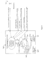
- FIG. 1 is a schematic block diagram of a resource management system according to an example.
- a management or allocation system 101 sits between multiple subscribers 103 and multiple physical battery devices 105.
- System 101 can be implemented on servers, platforms, the cloud, and so on and can be a distributed or centralized system.
- a subscriber 103 can communicate with system 101 using a common data network such as the internet for example, and data encryption to protect communications can be provided.
- physical storage devices and distributed power resources 105 such as batteries for example are decoupled from the storage-service subscribers 103 that want to utilize the electrical storage capabilities (virtual storages). Owners of the physical batteries 105 can thus offer their resources to the system 101, either in an automated fashion or with the use of a third party brokerage service for example.
- the system 101 communicates to Local Energy Management (LEM) units of the physical batteries 105.
- LEM Local Energy Management
- the system can then group the physical battery resources 105 dynamically together and is therefore able to offer energy storage services independently from single physical battery restrictions to any party (subscriber) who is interested in dealing in electrical storage capabilities.
- Such parties can be systems that deal with grid stability and grid operators for example, but also traders.
- system 101 provides a database 107 of physical storage resources 109.
- Each resource 109 can be distributed - that is, resources can be at different physical locations from one another.
- the different physical storages 109 (different locations, vendors, and operators) can be combined to form virtual entities 111 that can be stored in a virtual battery database 113.
- Entities 111 are virtual batteries, or virtual battery devices that can be instantiated for use by subscribers 103.
- a virtual battery can be instantiated on the basis of a subscriber requirement for example, and can provide a subscriber with capacity from one or more of the physical devices 109.
- the capacity of one physical device 109 can be split into smaller parts for use with multiple virtual resources 111.
- a virtual battery device 111 can be provided on demand, and splitting and combining of physical resources can be mixed. Also reallocation of storage resources can be provided.
- physical storage resource handling is separated from the subscribers of virtual resources. That is the owner/operator is not and need not to be aware of how their resources are used. There is neither a direct communication to storage subscribers nor direct communication between any physical devices. Therefore the operational interface to the physical entities need only use commands, such as those that exist in the local energy management (LEM) of the device, that can be offered over a data network, depicted broadly by the provision of the arrows in figure 1 .
- LEM local energy management
- FIG. 2 is a schematic block diagram of a resource management system and method according to an example, which gives an overview on the functions and interactions between the functional parts of the system.
- System 201 operates between subscribers 203 who will utilize a virtual battery device and physical device owners 205. Each party can register with system 201 thereby registering themselves as users (or providers) with the system. The step of registration can include authentication of a party.
- a subscriber 203 is allocated power from one or more physical devices via a virtual battery device. The operation of the virtual battery device can be controlled by system 201 based on an allocation that has been requested from a subscriber 203 and provided by one or more operators 205.
- FIG. 3 is a schematic block diagram of the device side of a resource management system and method according to an example.
- a physical battery device 301 is operational connected to the power grid 303.
- System 305 controls the registration, contracting and offering of capacity from device 301.
- a registration/authentication process, 2 takes place between system 305 and the local energy management system (LEM) of device 301.
- An offer is made (3), including an indication of capacity, power capabilities and device location and so on.
- System 305 can provide a contracting offer (4) in which the parameters that were provided in 3 can be accepted. This can be acknowledged (5) by LEM of device 301 and battery operation can be activated (6) on the basis of the contracted offering.
- physical access to the device 301 can be tested (7) in order to ensure that the offering can be successfully taken up.
- the system 305 can then add (8) the device 301 to a database of physical devices, and provide contracting confirmation (9). Accordingly, a physical device 301 can be added to a database 307 of system 305 with details of the capabilities of the device, and parameters under which usage of the capacity of the device can be utilized.
- Figure 4 is a schematic block diagram of the subscriber side of a resource management system and method according to an example.
- Service subscribers first have to go through a registration process (0), which can include authentication/authorization for example. Contracting can then be done either automatically or with the aid of manual support for example on the user/subscriber side.
- subscriber 401 generates an allocation request (1) for system 403.
- the request is a capacity allocation request from the subscriber that defines the capacity that the subscriber is seeking.
- System 403 uses the request to check against existing physical resources to see if the request can be accommodated.
- the database of physical resources 405 stores data relating to the physical devices 407, such as their location, capacity and so on.
- an offer (3) is made to subscriber 401, which is acknowledged (4) by subscriber 401. If the acknowledgement is in the positive, that is, if the offer is acceptable, an virtual battery 409 can be instantiated that is supported by capacity from one or more of the physical devices for which the system 403 has access.
- the virtual battery device 409 is part of a database of virtual devices 411 relating to multiple subscribers for example. In an example, the capacity of a virtual battery device can be scaled in response to a request from a subscriber that can be supported by system 403.
- a control interface (7) can be provided to enable subscriber 401 to monitor usage of the device 409 for example, and control aspects relating to the device 409.
- system 403 will thus find a storage solution that fits best to the subscriber's requirements by combining a set of physical energy storage devices (batteries) into a virtual energy storage device and making an offer to the user. If the user accepts, the operation procedure will be activated. In the case of a mismatch between request and offer, an optimization process can be started in which a best match can be found. This can increase the possible utilization of the storage devices.
- figure 5 is a flowchart of a method for power allocation according to an example, which shows an exemplary process for allocation and optimisation.
- Figure 6 is a schematic block diagram of a resource management system and method according to an example.
- a storage service user or subscriber 601 can manage his virtual storage according to his needs.
- the system 603 maps the requests towards the physical batteries 605 and offers monitoring capabilities and status information to the user 601.
- user 601 can make a status request (1) that can be passed to the control engines of the physical devices 605 from which status data (5) can be provided to the user 601.
- Figure 7 is a schematic block diagram of a resource management system and method according to an example, in which a control request from a user 701 is passed to the control management engines of physical devices 705 to determine certain control parameters associated with the physical devices 707 underlying the virtual device 707 in use by the user 701.
- the control parameter can include data such as the level of charge in a device 706 for example.
- figure 8 is a flowchart of a method for power allocation according to an example in which the process for a subscriber to check the status of physical resources is shown. In an example, in case of a failure during the operation a "hot reserve" can be activated to fulfill allocations and contracts.
- a storage owner is able to offer his storage capacity to a wider circle of subscribers and by this the utilization of the storage is higher.
- the storage device subscriber is able to select storage capacity from a wider circle of storage devices and by this the selection matches better to the subscribers demand.
- the overall utilization (and by this the efficiency) of the managed storage devices is higher than in case of isolated storage usage. This is achieved by running an optimization process and using small free capacities to 'fund' larger entities. Also the waste of partly allocated storage devices will be used. Free storage capacities of single storage devices can be assigned to different virtual storage entities, thus further enlarging the utilization of storage devices.
- the redundancy of the overall system is higher, because a cyclic redundancy check and optionally activation of a "hot reserve" can be provided.
- the cost of the overall system (compared to isolated storage usage) is lower because the available storage capacity can be dynamically shared to different subscribers, and the effort for installing and running such energy management system is low, because it can be integrated in existing management systems.
Abstract
Description
- Example embodiments relate in general to power allocation and resource management in connection with distributed electrical power storage devices.
- Use of renewable energy from sources that are continually replenished, such as sunlight, wind and tidal sources for example, is increasing. However, the fluctuating character of renewable energy production can be problematic. For example, transmission and distribution network operators have to take measures to prevent overload and underload conditions. Energy storage devices can be used to store energy when energy generation exceeds consumption and can also be used to provide stored energy into a network when generation figures are low and a high demand from consumers exists.
- Commonly, deployed electrical storage devices (batteries) are directed to one dedicated purpose such as, for example, peak shaving, power grid quality improvement, energy trading, and providing an uninterrupted power supply, and are typically distributed so that they are located at various geographical locations. Users will usually interact with their local grid operator to access such a battery.
- On the other hand there are parties (persons, machines; systems) that may use some electrical storage for a limited time with additional requirements such as for example requirements relating to energy storage capacity, power capability, power/energy at a defined location area, power/energy at a detailed position in a grid, special priorities of access to shared storage resources and timing requirements. Such parties can be grid operators or their Energy Management Systems (EMS), automated load-balancing systems, Demand Response (DR) or Demand Side Management (DMS) systems, or traders (persons and/or machines) for example.
- According to an aspect, there is provided a computer-implemented method for power allocation from multiple distributed power resources, comprising providing a subscriber registered with an allocation system with access to a virtual battery allocated a share of physical battery capacity derived from at least one of the multiple distributed power resources and instantiated on the basis of a capacity allocation request from the subscriber. The method can further include authenticating the subscriber with the allocation system, and providing the subscriber with an allocation offer of capacity based on the allocation request. The method can further include generating a measure representing the status of available physical resources from the multiple distributed power resources, and storing the measure as part of the allocation system. The virtual battery can be allocated a share of physical battery capacity from respective ones of a plurality of the multiple distributed power resources. A power resource of the multiple distributed power resources can provide capacity for multiple virtual batteries. The method can further include providing a database of distributed power resources including data representing capacity and capabilities of respective ones of the resources, and augmenting the database with additional resources on the basis of an offer from a registered resource owner. The method can further include testing physical access of the additional resources, and updating the data representing capabilities for the tested resources.
- According to an aspect, there is provided a computer program product, comprising a computer usable medium having computer readable program code embodied therein, said computer readable program code adapted to be executed to implement a method for power allocation from multiple distributed power resources as provided above.
- According to an aspect, there is provided a resource management system, comprising multiple physical power storage devices to support at least one virtual battery device instantiated in response to subscriber request data, and an authentication engine to control access to the virtual battery device by a subscriber and to enable a resource owner to offer a physical resource for the system. The system can further include a subscriber side contracting engine to receive the subscriber request data, and check available physical resources based on the request data to determine if a request for allocation of capacity of physical resources can be accommodated. The system can further include a device side contracting engine to receive offers from device owners or their representative software instances as e.g. local energy management systems. These offers can be committed by the device side contracting engine. The device side contracting engine works independently from the subscriber side contracting engine. The system can instantiate the virtual battery device and allocate a share of capacity of one or more of the physical power storage devices to the virtual battery device to accommodate the request for allocation. The system can further include a monitor engine to determine a status of a power storage device and update a database of physical resource capacity. The monitor engine can determine the status of a physical resource in response to data received from a subscriber relating to virtual battery device usage.
- Embodiments will now be described, by way of example only, with reference to the accompanying drawings, in which:
-
Figure 1 is a schematic block diagram of a resource management system according to an example; -
Figure 2 is a schematic block diagram of a resource management system and method according to an example; -
Figure 3 is a schematic block diagram of the device side of a resource management system and method according to an example; -
Figure 4 is a schematic block diagram of the subscriber side of a resource management system and method according to an example; -
Figure 5 is a flowchart of a method for power allocation according to an example; -
Figure 6 is a schematic block diagram of a resource management system and method according to an example; -
Figure 7 is a schematic block diagram of a resource management system and method according to an example; and -
Figure 8 is a flowchart of a method for power allocation according to an example. - Example embodiments are described below in sufficient detail to enable those of ordinary skill in the art to embody and implement the systems and processes herein described. It is important to understand that embodiments can be provided in many alternate forms and should not be construed as limited to the examples set forth herein.
- Accordingly, while embodiments can be modified in various ways and take on various alternative forms, specific embodiments thereof are shown in the drawings and described in detail below as examples. There is no intent to limit to the particular forms disclosed. On the contrary, all modifications, equivalents, and alternatives falling within the scope of the appended claims should be included. Elements of the example embodiments are consistently denoted by the same reference numerals throughout the drawings and detailed description where appropriate.
- The terminology used herein to describe embodiments is not intended to limit the scope. The articles "a," "an," and "the" are singular in that they have a single referent, however the use of the singular form in the present document should not preclude the presence of more than one referent. In other words, elements referred to in the singular can number one or more, unless the context clearly indicates otherwise. It will be further understood that the terms "comprises," "comprising," "includes," and/or "including," when used herein, specify the presence of stated features, items, steps, operations, elements, and/or components, but do not preclude the presence or addition of one or more other features, items, steps, operations, elements, components, and/or groups thereof.
- Unless otherwise defined, all terms (including technical and scientific terms) used herein are to be interpreted as is customary in the art. It will be further understood that terms in common usage should also be interpreted as is customary in the relevant art and not in an idealized or overly formal sense unless expressly so defined herein.
-
Figure 1 is a schematic block diagram of a resource management system according to an example. A management orallocation system 101 sits betweenmultiple subscribers 103 and multiplephysical battery devices 105. System 101 can be implemented on servers, platforms, the cloud, and so on and can be a distributed or centralized system. - A
subscriber 103 can communicate withsystem 101 using a common data network such as the internet for example, and data encryption to protect communications can be provided. According to an example, physical storage devices and distributedpower resources 105 such as batteries for example are decoupled from the storage-service subscribers 103 that want to utilize the electrical storage capabilities (virtual storages). Owners of thephysical batteries 105 can thus offer their resources to thesystem 101, either in an automated fashion or with the use of a third party brokerage service for example. Thesystem 101 communicates to Local Energy Management (LEM) units of thephysical batteries 105. The system can then group thephysical battery resources 105 dynamically together and is therefore able to offer energy storage services independently from single physical battery restrictions to any party (subscriber) who is interested in dealing in electrical storage capabilities. Such parties can be systems that deal with grid stability and grid operators for example, but also traders. - According to an example,
system 101 provides adatabase 107 ofphysical storage resources 109. Eachresource 109 can be distributed - that is, resources can be at different physical locations from one another. The different physical storages 109 (different locations, vendors, and operators) can be combined to form virtual entities 111 that can be stored in avirtual battery database 113. Entities 111 are virtual batteries, or virtual battery devices that can be instantiated for use bysubscribers 103. A virtual battery can be instantiated on the basis of a subscriber requirement for example, and can provide a subscriber with capacity from one or more of thephysical devices 109. In an example, the capacity of onephysical device 109 can be split into smaller parts for use with multiple virtual resources 111. - A virtual battery device 111 can be provided on demand, and splitting and combining of physical resources can be mixed. Also reallocation of storage resources can be provided. In an example, physical storage resource handling is separated from the subscribers of virtual resources. That is the owner/operator is not and need not to be aware of how their resources are used. There is neither a direct communication to storage subscribers nor direct communication between any physical devices. Therefore the operational interface to the physical entities need only use commands, such as those that exist in the local energy management (LEM) of the device, that can be offered over a data network, depicted broadly by the provision of the arrows in
figure 1 . -
Figure 2 is a schematic block diagram of a resource management system and method according to an example, which gives an overview on the functions and interactions between the functional parts of the system.System 201 operates betweensubscribers 203 who will utilize a virtual battery device andphysical device owners 205. Each party can register withsystem 201 thereby registering themselves as users (or providers) with the system. The step of registration can include authentication of a party. At 207, asubscriber 203 is allocated power from one or more physical devices via a virtual battery device. The operation of the virtual battery device can be controlled bysystem 201 based on an allocation that has been requested from asubscriber 203 and provided by one ormore operators 205. -
Figure 3 is a schematic block diagram of the device side of a resource management system and method according to an example. A physical battery device 301 is operational connected to thepower grid 303. System 305 controls the registration, contracting and offering of capacity from device 301. A registration/authentication process, 2, takes place between system 305 and the local energy management system (LEM) of device 301. An offer is made (3), including an indication of capacity, power capabilities and device location and so on. System 305 can provide a contracting offer (4) in which the parameters that were provided in 3 can be accepted. This can be acknowledged (5) by LEM of device 301 and battery operation can be activated (6) on the basis of the contracted offering. Optionally, physical access to the device 301 can be tested (7) in order to ensure that the offering can be successfully taken up. The system 305 can then add (8) the device 301 to a database of physical devices, and provide contracting confirmation (9). Accordingly, a physical device 301 can be added to adatabase 307 of system 305 with details of the capabilities of the device, and parameters under which usage of the capacity of the device can be utilized. -
Figure 4 is a schematic block diagram of the subscriber side of a resource management system and method according to an example. Service subscribers first have to go through a registration process (0), which can include authentication/authorization for example. Contracting can then be done either automatically or with the aid of manual support for example on the user/subscriber side. In an example, subscriber 401 generates an allocation request (1) forsystem 403. The request is a capacity allocation request from the subscriber that defines the capacity that the subscriber is seeking.System 403 uses the request to check against existing physical resources to see if the request can be accommodated. For example, the database ofphysical resources 405 stores data relating to thephysical devices 407, such as their location, capacity and so on. If sufficient resources exist, an offer (3) is made to subscriber 401, which is acknowledged (4) by subscriber 401. If the acknowledgement is in the positive, that is, if the offer is acceptable, anvirtual battery 409 can be instantiated that is supported by capacity from one or more of the physical devices for which thesystem 403 has access. Thevirtual battery device 409 is part of a database ofvirtual devices 411 relating to multiple subscribers for example. In an example, the capacity of a virtual battery device can be scaled in response to a request from a subscriber that can be supported bysystem 403. - In use of
virtual battery device 409, a control interface (7) can be provided to enable subscriber 401 to monitor usage of thedevice 409 for example, and control aspects relating to thedevice 409. - Typically,
system 403 will thus find a storage solution that fits best to the subscriber's requirements by combining a set of physical energy storage devices (batteries) into a virtual energy storage device and making an offer to the user. If the user accepts, the operation procedure will be activated. In the case of a mismatch between request and offer, an optimization process can be started in which a best match can be found. This can increase the possible utilization of the storage devices. In this connection,figure 5 is a flowchart of a method for power allocation according to an example, which shows an exemplary process for allocation and optimisation. -
Figure 6 is a schematic block diagram of a resource management system and method according to an example. A storage service user orsubscriber 601 can manage his virtual storage according to his needs. Thesystem 603 maps the requests towards thephysical batteries 605 and offers monitoring capabilities and status information to theuser 601. For example,user 601 can make a status request (1) that can be passed to the control engines of thephysical devices 605 from which status data (5) can be provided to theuser 601. -
Figure 7 is a schematic block diagram of a resource management system and method according to an example, in which a control request from a user 701 is passed to the control management engines ofphysical devices 705 to determine certain control parameters associated with thephysical devices 707 underlying thevirtual device 707 in use by the user 701. The control parameter can include data such as the level of charge in adevice 706 for example. In this connection,figure 8 is a flowchart of a method for power allocation according to an example in which the process for a subscriber to check the status of physical resources is shown. In an example, in case of a failure during the operation a "hot reserve" can be activated to fulfill allocations and contracts. - Accordingly, a storage owner is able to offer his storage capacity to a wider circle of subscribers and by this the utilization of the storage is higher. The storage device subscriber is able to select storage capacity from a wider circle of storage devices and by this the selection matches better to the subscribers demand.
- Thus, the overall utilization (and by this the efficiency) of the managed storage devices is higher than in case of isolated storage usage. This is achieved by running an optimization process and using small free capacities to 'fund' larger entities. Also the waste of partly allocated storage devices will be used. Free storage capacities of single storage devices can be assigned to different virtual storage entities, thus further enlarging the utilization of storage devices. The redundancy of the overall system is higher, because a cyclic redundancy check and optionally activation of a "hot reserve" can be provided. The cost of the overall system (compared to isolated storage usage) is lower because the available storage capacity can be dynamically shared to different subscribers, and the effort for installing and running such energy management system is low, because it can be integrated in existing management systems.
- The present inventions may be embodied in other specific apparatus and/or methods. The described embodiments are to be considered in all respects as illustrative and not restrictive. In particular, the scope of the invention is indicated by the appended claims rather than by the description and figures herein. All changes that come within the meaning and range of equivalency of the claims are to be embraced within their scope.
Claims (15)
- A computer-implemented method for power allocation from multiple distributed power resources, comprising:providing a subscriber registered with an allocation system with access to a virtual battery allocated a share of physical battery capacity derived from at least one of the multiple distributed power resources and instantiated on the basis of a capacity allocation request from the subscriber.
- A method as claimed in claim 1, further including:authenticating the subscriber with the allocation system; andproviding the subscriber with an allocation offer of capacity based on the allocation request.
- A method as claimed in claim 1 or 2, further including:generating a measure representing the status of available physical resources from the multiple distributed power resources;storing the measure as part of the allocation system.
- A method as claimed in any preceding claim, wherein the virtual battery is allocated a share of physical battery capacity from respective ones of a plurality of the multiple distributed power resources.
- A method as claimed in any preceding claim, wherein a power resource of the multiple distributed power resources provides capacity for multiple virtual batteries.
- A method as claimed in any preceding claim, further including:providing a database of distributed power resources including data representing capacity and capabilities of respective ones of the resources;augmenting the database with additional resources on the basis of an offer from a registered resource owner.
- A method as claimed in claim 6, further including:testing physical access of the additional resources; andupdating the data representing capabilities for the tested resources.
- A computer program product, comprising a computer usable medium having computer readable program code embodied therein, said computer readable program code adapted to be executed to implement a method for power allocation from multiple distributed power resources as claimed in any preceding claim.
- A resource management system, comprising:multiple physical power storage devices to support at least one virtual battery device instantiated in response to subscriber request data;an authentication engine to control access to the virtual battery device by a subscriber and to enable a resource owner to offer a physical resource for the system.
- A system as claimed in claim 9, further including a subscriber side contracting engine to:receive the subscriber request data; andcheck available physical resources based on the request data to determine if a request for allocation of capacity of physical resources can be accommodated.
- A system as claimed in claim 10, further including a device side contracting engine to receive offers from device owners or their representative instances.
- A system as claimed in claim 11, wherein the device side contracting engine works independently from the subscriber side contracting engine
- A system as claimed in any claims 10 to 12, wherein the system is operable to instantiate the virtual battery device and allocate a share of capacity of one or more of the physical power storage devices to the virtual battery device to accommodate the request for allocation.
- A system as claimed in any of claims 9 to 13, further including:a monitor engine to determine a status of a power storage device and update a database of physical resource capacity.
- A system as claimed in claim 14, wherein the monitor engine is further operable to determine the status of a physical resource in response to data received from a subscriber relating to virtual battery device usage.
Priority Applications (1)
| Application Number | Priority Date | Filing Date | Title |
|---|---|---|---|
| EP13360013.0A EP2822140B1 (en) | 2013-07-04 | 2013-07-04 | Method for power allocation and resource management system |
Applications Claiming Priority (1)
| Application Number | Priority Date | Filing Date | Title |
|---|---|---|---|
| EP13360013.0A EP2822140B1 (en) | 2013-07-04 | 2013-07-04 | Method for power allocation and resource management system |
Publications (2)
| Publication Number | Publication Date |
|---|---|
| EP2822140A1 true EP2822140A1 (en) | 2015-01-07 |
| EP2822140B1 EP2822140B1 (en) | 2016-11-02 |
Family
ID=48900921
Family Applications (1)
| Application Number | Title | Priority Date | Filing Date |
|---|---|---|---|
| EP13360013.0A Not-in-force EP2822140B1 (en) | 2013-07-04 | 2013-07-04 | Method for power allocation and resource management system |
Country Status (1)
| Country | Link |
|---|---|
| EP (1) | EP2822140B1 (en) |
Cited By (5)
| Publication number | Priority date | Publication date | Assignee | Title |
|---|---|---|---|---|
| CN107069782A (en) * | 2016-11-29 | 2017-08-18 | 北京交通大学 | Capacity collocation method applied to rail transportation vehicle-mounted mixed energy storage system |
| JPWO2016136263A1 (en) * | 2015-02-25 | 2017-08-24 | 京セラ株式会社 | Power control system, power control apparatus, and power control method |
| WO2021019444A1 (en) * | 2019-07-29 | 2021-02-04 | Eco Home As | Method and system for using second life batteries as energy storage in a renewable energy system |
| EP3748799A4 (en) * | 2018-01-30 | 2021-10-27 | Kyocera Corporation | Power management server and power management method |
| US11522387B2 (en) * | 2017-12-18 | 2022-12-06 | International Business Machines Corporation | Virtualization of large-scale energy storage |
Citations (3)
| Publication number | Priority date | Publication date | Assignee | Title |
|---|---|---|---|---|
| US20060214638A1 (en) * | 2003-10-17 | 2006-09-28 | Chen Joseph C | Battery management system and method |
| US20100023940A1 (en) * | 2008-07-28 | 2010-01-28 | Fujitsu Limited | Virtual machine system |
| US20120176091A1 (en) * | 2009-10-05 | 2012-07-12 | Ngk Insulators, Inc. | Control apparatus, control apparatus network and control method |
-
2013
- 2013-07-04 EP EP13360013.0A patent/EP2822140B1/en not_active Not-in-force
Patent Citations (3)
| Publication number | Priority date | Publication date | Assignee | Title |
|---|---|---|---|---|
| US20060214638A1 (en) * | 2003-10-17 | 2006-09-28 | Chen Joseph C | Battery management system and method |
| US20100023940A1 (en) * | 2008-07-28 | 2010-01-28 | Fujitsu Limited | Virtual machine system |
| US20120176091A1 (en) * | 2009-10-05 | 2012-07-12 | Ngk Insulators, Inc. | Control apparatus, control apparatus network and control method |
Cited By (10)
| Publication number | Priority date | Publication date | Assignee | Title |
|---|---|---|---|---|
| JPWO2016136263A1 (en) * | 2015-02-25 | 2017-08-24 | 京セラ株式会社 | Power control system, power control apparatus, and power control method |
| EP3264555A4 (en) * | 2015-02-25 | 2018-09-05 | KYOCERA Corporation | Electric power control system, electric power control device, and electric power control method |
| JP2019092386A (en) * | 2015-02-25 | 2019-06-13 | 京セラ株式会社 | Power control system, power control unit, and power control method |
| US10535999B2 (en) | 2015-02-25 | 2020-01-14 | Kyocera Corporation | Power control system, power control apparatus, and power control method |
| US11258259B2 (en) | 2015-02-25 | 2022-02-22 | Kyocera Corporation | Power control system, power control apparatus, and power control method |
| CN107069782A (en) * | 2016-11-29 | 2017-08-18 | 北京交通大学 | Capacity collocation method applied to rail transportation vehicle-mounted mixed energy storage system |
| CN107069782B (en) * | 2016-11-29 | 2020-02-04 | 北京交通大学 | Capacity configuration method applied to rail transit vehicle-mounted hybrid energy storage system |
| US11522387B2 (en) * | 2017-12-18 | 2022-12-06 | International Business Machines Corporation | Virtualization of large-scale energy storage |
| EP3748799A4 (en) * | 2018-01-30 | 2021-10-27 | Kyocera Corporation | Power management server and power management method |
| WO2021019444A1 (en) * | 2019-07-29 | 2021-02-04 | Eco Home As | Method and system for using second life batteries as energy storage in a renewable energy system |
Also Published As
| Publication number | Publication date |
|---|---|
| EP2822140B1 (en) | 2016-11-02 |
Similar Documents
| Publication | Publication Date | Title |
|---|---|---|
| CN110636103B (en) | Unified scheduling method for multi-heterogeneous cluster jobs and API (application program interface) | |
| EP2822140B1 (en) | Method for power allocation and resource management system | |
| CN103516807B (en) | A kind of cloud computing platform server load balancing system and method | |
| CN105279027B (en) | A kind of virtual machine deployment method and device | |
| CN108879831B (en) | Power distribution system, capacity sharing system, master station, slave station, method and equipment | |
| CN106453146B (en) | Method, system, device and readable storage medium for allocating private cloud computing resources | |
| CN102567106B (en) | Task scheduling method, system and device | |
| CN109688222A (en) | The dispatching method of shared computing resource, shared computing system, server and storage medium | |
| CN106657287A (en) | Data access method and system | |
| CN108923479B (en) | Power distribution system, capacity sharing system, server, terminal, method and equipment | |
| CN104281496A (en) | Virtual resource distribution method and virtual resource distribution device | |
| US20170041384A1 (en) | Cloud service broker apparatus and method thereof | |
| CN102067098A (en) | Hierarchical policy management | |
| CN105103506A (en) | Network function virtualization method and device | |
| CN109617986A (en) | A kind of load-balancing method and the network equipment | |
| CN106790636A (en) | A kind of equally loaded system and method for cloud computing server cluster | |
| CN105446817B (en) | A kind of federated resource configuration of reservations algorithm based on robust optimization in mobile cloud computing | |
| CN110796343A (en) | Intelligent dispatching method, device and system | |
| US9519441B1 (en) | Automated storage provisioning and management using a centralized database | |
| CN105357199A (en) | Cloud computing cognitive resource management system and method | |
| CN103997523A (en) | Smart city service system based on cloud services and implementation method thereof | |
| CN104468737A (en) | Storage hierarchical scheduling method and system based on service type characteristics | |
| CN106790482A (en) | Resource regulating method and resource scheduling system | |
| CN110086726A (en) | A method of automatically switching Kubernetes host node | |
| CN106295823A (en) | A kind of APP based on user's differentiation preengages system and method for hiring a car |
Legal Events
| Date | Code | Title | Description |
|---|---|---|---|
| PUAI | Public reference made under article 153(3) epc to a published international application that has entered the european phase |
Free format text: ORIGINAL CODE: 0009012 |
|
| 17P | Request for examination filed |
Effective date: 20140514 |
|
| AK | Designated contracting states |
Kind code of ref document: A1 Designated state(s): AL AT BE BG CH CY CZ DE DK EE ES FI FR GB GR HR HU IE IS IT LI LT LU LV MC MK MT NL NO PL PT RO RS SE SI SK SM TR |
|
| AX | Request for extension of the european patent |
Extension state: BA ME |
|
| RBV | Designated contracting states (corrected) |
Designated state(s): AL AT BE BG CH CY CZ DE DK EE ES FI FR GB GR HR HU IE IS IT LI LT LU LV MC MK MT NL NO PL PT RO RS SE SI SK SM TR |
|
| REG | Reference to a national code |
Ref country code: DE Ref legal event code: R079 Ref document number: 602013013439 Country of ref document: DE Free format text: PREVIOUS MAIN CLASS: H02J0007000000 Ipc: G06F0001260000 |
|
| GRAP | Despatch of communication of intention to grant a patent |
Free format text: ORIGINAL CODE: EPIDOSNIGR1 |
|
| RIC1 | Information provided on ipc code assigned before grant |
Ipc: G06F 1/26 20060101AFI20160504BHEP Ipc: H02J 7/00 20060101ALI20160504BHEP |
|
| INTG | Intention to grant announced |
Effective date: 20160530 |
|
| GRAS | Grant fee paid |
Free format text: ORIGINAL CODE: EPIDOSNIGR3 |
|
| GRAA | (expected) grant |
Free format text: ORIGINAL CODE: 0009210 |
|
| AK | Designated contracting states |
Kind code of ref document: B1 Designated state(s): AL AT BE BG CH CY CZ DE DK EE ES FI FR GB GR HR HU IE IS IT LI LT LU LV MC MK MT NL NO PL PT RO RS SE SI SK SM TR |
|
| REG | Reference to a national code |
Ref country code: GB Ref legal event code: FG4D |
|
| REG | Reference to a national code |
Ref country code: AT Ref legal event code: REF Ref document number: 842446 Country of ref document: AT Kind code of ref document: T Effective date: 20161115 Ref country code: CH Ref legal event code: EP |
|
| REG | Reference to a national code |
Ref country code: IE Ref legal event code: FG4D |
|
| REG | Reference to a national code |
Ref country code: DE Ref legal event code: R096 Ref document number: 602013013439 Country of ref document: DE |
|
| PG25 | Lapsed in a contracting state [announced via postgrant information from national office to epo] |
Ref country code: LV Free format text: LAPSE BECAUSE OF FAILURE TO SUBMIT A TRANSLATION OF THE DESCRIPTION OR TO PAY THE FEE WITHIN THE PRESCRIBED TIME-LIMIT Effective date: 20161102 |
|
| REG | Reference to a national code |
Ref country code: NL Ref legal event code: MP Effective date: 20161102 |
|
| REG | Reference to a national code |
Ref country code: LT Ref legal event code: MG4D |
|
| REG | Reference to a national code |
Ref country code: AT Ref legal event code: MK05 Ref document number: 842446 Country of ref document: AT Kind code of ref document: T Effective date: 20161102 |
|
| PG25 | Lapsed in a contracting state [announced via postgrant information from national office to epo] |
Ref country code: GR Free format text: LAPSE BECAUSE OF FAILURE TO SUBMIT A TRANSLATION OF THE DESCRIPTION OR TO PAY THE FEE WITHIN THE PRESCRIBED TIME-LIMIT Effective date: 20170203 Ref country code: NO Free format text: LAPSE BECAUSE OF FAILURE TO SUBMIT A TRANSLATION OF THE DESCRIPTION OR TO PAY THE FEE WITHIN THE PRESCRIBED TIME-LIMIT Effective date: 20170202 Ref country code: NL Free format text: LAPSE BECAUSE OF FAILURE TO SUBMIT A TRANSLATION OF THE DESCRIPTION OR TO PAY THE FEE WITHIN THE PRESCRIBED TIME-LIMIT Effective date: 20161102 Ref country code: SE Free format text: LAPSE BECAUSE OF FAILURE TO SUBMIT A TRANSLATION OF THE DESCRIPTION OR TO PAY THE FEE WITHIN THE PRESCRIBED TIME-LIMIT Effective date: 20161102 Ref country code: LT Free format text: LAPSE BECAUSE OF FAILURE TO SUBMIT A TRANSLATION OF THE DESCRIPTION OR TO PAY THE FEE WITHIN THE PRESCRIBED TIME-LIMIT Effective date: 20161102 |
|
| PG25 | Lapsed in a contracting state [announced via postgrant information from national office to epo] |
Ref country code: PT Free format text: LAPSE BECAUSE OF FAILURE TO SUBMIT A TRANSLATION OF THE DESCRIPTION OR TO PAY THE FEE WITHIN THE PRESCRIBED TIME-LIMIT Effective date: 20170302 Ref country code: RS Free format text: LAPSE BECAUSE OF FAILURE TO SUBMIT A TRANSLATION OF THE DESCRIPTION OR TO PAY THE FEE WITHIN THE PRESCRIBED TIME-LIMIT Effective date: 20161102 Ref country code: IS Free format text: LAPSE BECAUSE OF FAILURE TO SUBMIT A TRANSLATION OF THE DESCRIPTION OR TO PAY THE FEE WITHIN THE PRESCRIBED TIME-LIMIT Effective date: 20170302 Ref country code: AT Free format text: LAPSE BECAUSE OF FAILURE TO SUBMIT A TRANSLATION OF THE DESCRIPTION OR TO PAY THE FEE WITHIN THE PRESCRIBED TIME-LIMIT Effective date: 20161102 Ref country code: FI Free format text: LAPSE BECAUSE OF FAILURE TO SUBMIT A TRANSLATION OF THE DESCRIPTION OR TO PAY THE FEE WITHIN THE PRESCRIBED TIME-LIMIT Effective date: 20161102 Ref country code: PL Free format text: LAPSE BECAUSE OF FAILURE TO SUBMIT A TRANSLATION OF THE DESCRIPTION OR TO PAY THE FEE WITHIN THE PRESCRIBED TIME-LIMIT Effective date: 20161102 Ref country code: ES Free format text: LAPSE BECAUSE OF FAILURE TO SUBMIT A TRANSLATION OF THE DESCRIPTION OR TO PAY THE FEE WITHIN THE PRESCRIBED TIME-LIMIT Effective date: 20161102 Ref country code: HR Free format text: LAPSE BECAUSE OF FAILURE TO SUBMIT A TRANSLATION OF THE DESCRIPTION OR TO PAY THE FEE WITHIN THE PRESCRIBED TIME-LIMIT Effective date: 20161102 |
|
| REG | Reference to a national code |
Ref country code: FR Ref legal event code: PLFP Year of fee payment: 5 |
|
| PG25 | Lapsed in a contracting state [announced via postgrant information from national office to epo] |
Ref country code: SK Free format text: LAPSE BECAUSE OF FAILURE TO SUBMIT A TRANSLATION OF THE DESCRIPTION OR TO PAY THE FEE WITHIN THE PRESCRIBED TIME-LIMIT Effective date: 20161102 Ref country code: DK Free format text: LAPSE BECAUSE OF FAILURE TO SUBMIT A TRANSLATION OF THE DESCRIPTION OR TO PAY THE FEE WITHIN THE PRESCRIBED TIME-LIMIT Effective date: 20161102 Ref country code: RO Free format text: LAPSE BECAUSE OF FAILURE TO SUBMIT A TRANSLATION OF THE DESCRIPTION OR TO PAY THE FEE WITHIN THE PRESCRIBED TIME-LIMIT Effective date: 20161102 Ref country code: CZ Free format text: LAPSE BECAUSE OF FAILURE TO SUBMIT A TRANSLATION OF THE DESCRIPTION OR TO PAY THE FEE WITHIN THE PRESCRIBED TIME-LIMIT Effective date: 20161102 Ref country code: EE Free format text: LAPSE BECAUSE OF FAILURE TO SUBMIT A TRANSLATION OF THE DESCRIPTION OR TO PAY THE FEE WITHIN THE PRESCRIBED TIME-LIMIT Effective date: 20161102 |
|
| REG | Reference to a national code |
Ref country code: DE Ref legal event code: R097 Ref document number: 602013013439 Country of ref document: DE |
|
| PG25 | Lapsed in a contracting state [announced via postgrant information from national office to epo] |
Ref country code: BG Free format text: LAPSE BECAUSE OF FAILURE TO SUBMIT A TRANSLATION OF THE DESCRIPTION OR TO PAY THE FEE WITHIN THE PRESCRIBED TIME-LIMIT Effective date: 20170202 Ref country code: SM Free format text: LAPSE BECAUSE OF FAILURE TO SUBMIT A TRANSLATION OF THE DESCRIPTION OR TO PAY THE FEE WITHIN THE PRESCRIBED TIME-LIMIT Effective date: 20161102 Ref country code: IT Free format text: LAPSE BECAUSE OF FAILURE TO SUBMIT A TRANSLATION OF THE DESCRIPTION OR TO PAY THE FEE WITHIN THE PRESCRIBED TIME-LIMIT Effective date: 20161102 Ref country code: BE Free format text: LAPSE BECAUSE OF FAILURE TO SUBMIT A TRANSLATION OF THE DESCRIPTION OR TO PAY THE FEE WITHIN THE PRESCRIBED TIME-LIMIT Effective date: 20161102 |
|
| PLBE | No opposition filed within time limit |
Free format text: ORIGINAL CODE: 0009261 |
|
| STAA | Information on the status of an ep patent application or granted ep patent |
Free format text: STATUS: NO OPPOSITION FILED WITHIN TIME LIMIT |
|
| 26N | No opposition filed |
Effective date: 20170803 |
|
| PG25 | Lapsed in a contracting state [announced via postgrant information from national office to epo] |
Ref country code: SI Free format text: LAPSE BECAUSE OF FAILURE TO SUBMIT A TRANSLATION OF THE DESCRIPTION OR TO PAY THE FEE WITHIN THE PRESCRIBED TIME-LIMIT Effective date: 20161102 |
|
| REG | Reference to a national code |
Ref country code: CH Ref legal event code: PL |
|
| REG | Reference to a national code |
Ref country code: IE Ref legal event code: MM4A |
|
| PG25 | Lapsed in a contracting state [announced via postgrant information from national office to epo] |
Ref country code: CH Free format text: LAPSE BECAUSE OF NON-PAYMENT OF DUE FEES Effective date: 20170731 Ref country code: IE Free format text: LAPSE BECAUSE OF NON-PAYMENT OF DUE FEES Effective date: 20170704 Ref country code: LI Free format text: LAPSE BECAUSE OF NON-PAYMENT OF DUE FEES Effective date: 20170731 |
|
| PG25 | Lapsed in a contracting state [announced via postgrant information from national office to epo] |
Ref country code: LU Free format text: LAPSE BECAUSE OF NON-PAYMENT OF DUE FEES Effective date: 20170704 |
|
| REG | Reference to a national code |
Ref country code: FR Ref legal event code: PLFP Year of fee payment: 6 |
|
| PG25 | Lapsed in a contracting state [announced via postgrant information from national office to epo] |
Ref country code: MT Free format text: LAPSE BECAUSE OF NON-PAYMENT OF DUE FEES Effective date: 20170704 |
|
| PG25 | Lapsed in a contracting state [announced via postgrant information from national office to epo] |
Ref country code: HU Free format text: LAPSE BECAUSE OF FAILURE TO SUBMIT A TRANSLATION OF THE DESCRIPTION OR TO PAY THE FEE WITHIN THE PRESCRIBED TIME-LIMIT; INVALID AB INITIO Effective date: 20130704 Ref country code: MC Free format text: LAPSE BECAUSE OF FAILURE TO SUBMIT A TRANSLATION OF THE DESCRIPTION OR TO PAY THE FEE WITHIN THE PRESCRIBED TIME-LIMIT Effective date: 20161102 |
|
| PGFP | Annual fee paid to national office [announced via postgrant information from national office to epo] |
Ref country code: FR Payment date: 20190619 Year of fee payment: 7 |
|
| PG25 | Lapsed in a contracting state [announced via postgrant information from national office to epo] |
Ref country code: CY Free format text: LAPSE BECAUSE OF FAILURE TO SUBMIT A TRANSLATION OF THE DESCRIPTION OR TO PAY THE FEE WITHIN THE PRESCRIBED TIME-LIMIT Effective date: 20161102 |
|
| PGFP | Annual fee paid to national office [announced via postgrant information from national office to epo] |
Ref country code: DE Payment date: 20190618 Year of fee payment: 7 |
|
| PG25 | Lapsed in a contracting state [announced via postgrant information from national office to epo] |
Ref country code: MK Free format text: LAPSE BECAUSE OF FAILURE TO SUBMIT A TRANSLATION OF THE DESCRIPTION OR TO PAY THE FEE WITHIN THE PRESCRIBED TIME-LIMIT Effective date: 20161102 |
|
| PGFP | Annual fee paid to national office [announced via postgrant information from national office to epo] |
Ref country code: GB Payment date: 20190703 Year of fee payment: 7 |
|
| PG25 | Lapsed in a contracting state [announced via postgrant information from national office to epo] |
Ref country code: TR Free format text: LAPSE BECAUSE OF FAILURE TO SUBMIT A TRANSLATION OF THE DESCRIPTION OR TO PAY THE FEE WITHIN THE PRESCRIBED TIME-LIMIT Effective date: 20161102 |
|
| PG25 | Lapsed in a contracting state [announced via postgrant information from national office to epo] |
Ref country code: AL Free format text: LAPSE BECAUSE OF FAILURE TO SUBMIT A TRANSLATION OF THE DESCRIPTION OR TO PAY THE FEE WITHIN THE PRESCRIBED TIME-LIMIT Effective date: 20161102 |
|
| REG | Reference to a national code |
Ref country code: DE Ref legal event code: R119 Ref document number: 602013013439 Country of ref document: DE |
|
| GBPC | Gb: european patent ceased through non-payment of renewal fee |
Effective date: 20200704 |
|
| PG25 | Lapsed in a contracting state [announced via postgrant information from national office to epo] |
Ref country code: FR Free format text: LAPSE BECAUSE OF NON-PAYMENT OF DUE FEES Effective date: 20200731 Ref country code: GB Free format text: LAPSE BECAUSE OF NON-PAYMENT OF DUE FEES Effective date: 20200704 |
|
| PG25 | Lapsed in a contracting state [announced via postgrant information from national office to epo] |
Ref country code: DE Free format text: LAPSE BECAUSE OF NON-PAYMENT OF DUE FEES Effective date: 20210202 |