EP2821976A1 - Verfahren und Vorrichtung zur Aufzeichnung von Ereignissen in Selbstbedienungsautomaten - Google Patents
Verfahren und Vorrichtung zur Aufzeichnung von Ereignissen in Selbstbedienungsautomaten Download PDFInfo
- Publication number
- EP2821976A1 EP2821976A1 EP13174518.4A EP13174518A EP2821976A1 EP 2821976 A1 EP2821976 A1 EP 2821976A1 EP 13174518 A EP13174518 A EP 13174518A EP 2821976 A1 EP2821976 A1 EP 2821976A1
- Authority
- EP
- European Patent Office
- Prior art keywords
- self
- monitoring
- control unit
- service machine
- machine according
- Prior art date
- Legal status (The legal status is an assumption and is not a legal conclusion. Google has not performed a legal analysis and makes no representation as to the accuracy of the status listed.)
- Granted
Links
Images
Classifications
-
- G—PHYSICS
- G07—CHECKING-DEVICES
- G07F—COIN-FREED OR LIKE APPARATUS
- G07F19/00—Complete banking systems; Coded card-freed arrangements adapted for dispensing or receiving monies or the like and posting such transactions to existing accounts, e.g. automatic teller machines
- G07F19/20—Automatic teller machines [ATMs]
- G07F19/207—Surveillance aspects at ATMs
-
- G—PHYSICS
- G07—CHECKING-DEVICES
- G07F—COIN-FREED OR LIKE APPARATUS
- G07F19/00—Complete banking systems; Coded card-freed arrangements adapted for dispensing or receiving monies or the like and posting such transactions to existing accounts, e.g. automatic teller machines
- G07F19/20—Automatic teller machines [ATMs]
- G07F19/205—Housing aspects of ATMs
- G07F19/2055—Anti-skimming aspects at ATMs
-
- G—PHYSICS
- G07—CHECKING-DEVICES
- G07F—COIN-FREED OR LIKE APPARATUS
- G07F19/00—Complete banking systems; Coded card-freed arrangements adapted for dispensing or receiving monies or the like and posting such transactions to existing accounts, e.g. automatic teller machines
- G07F19/20—Automatic teller machines [ATMs]
- G07F19/209—Monitoring, auditing or diagnose of functioning of ATMs
-
- G—PHYSICS
- G07—CHECKING-DEVICES
- G07F—COIN-FREED OR LIKE APPARATUS
- G07F9/00—Details other than those peculiar to special kinds or types of apparatus
- G07F9/02—Devices for alarm or indication, e.g. when empty; Advertising arrangements in coin-freed apparatus
- G07F9/026—Devices for alarm or indication, e.g. when empty; Advertising arrangements in coin-freed apparatus for alarm, monitoring and auditing in vending machines or means for indication, e.g. when empty
Definitions
- the invention relates to a method and a device for recording events in self-service machines.
- Self-service machines often have a number of components to be interconnected. As a rule, these machines have a standardized PC platform that meets special security requirements. At this PC platform (motherboard), e.g. Connected via USB (Universal Serial Bus) interfaces to keyboards, payoff units (banknote divider module), card readers, monitors, and other devices. It should also be noted that ATMs are inserted in ATMs which are to be authenticated or the ATM has to authenticate itself to the cartridge in order to enable it to function.
- USB Universal Serial Bus
- these machines include the ability to connect to another computer so that, for example, a maintenance engineer can connect his laptop to the self-service machine.
- USB or other serial (V24) connections are used to connect the devices together.
- a security-relevant component in a self-service machine referred to below as an ATM
- Such a component could include a hardware module such as be a cashbox, but also a software component such as e.g. a firmware update, or even peripheral devices, as described above.
- a hardware module such as be a cashbox
- a software component such as e.g. a firmware update, or even peripheral devices, as described above.
- the ATM PC
- the ATM is authenticated to the new component or the ATM can verify the authenticity of the component. Only after successful authentication does the new component perform its service.
- ATMs are attacked by hardware manipulation. Or the staff tries to gain access to the device by exploiting hardware errors to enrich themselves. Since the ATMs sometimes have no way to independently monitor the hardware during a maintenance in which they are shut down and shut down, the devices are especially vulnerable and can hardly check themselves.
- the object of the present invention is to provide a system which performs further monitoring independently of the operation of the ATM (Automatic Teller Machine), wherein an external power supply is not necessary to record what is currently being done.
- the system's log can provide further clues to the perpetrators or their procedures, making it easier to prove. In this way, the system can not only log the state of the system, but also record further information such as picture or sound material.
- this consists of a vault and a control unit that controls the cash flow from the vault.
- This control unit is typically the PC described above that interacts with the user.
- access can be logged via a camera in the vault.
- the system could be connected via network or USB to the PC of the ATM be connected and record there via a software agent information.
- the status of the PC can be logged.
- the invention relates to a self-service machine comprising a control unit and a safe.
- This unit is additionally characterized by a monitoring unit, which is arranged in the vault, and by an independent power supply performs an acoustic, optical and / or electronic monitoring of the control unit.
- the arrangement may be formed in the vault so that a physical foreclosure against the cash boxes within the vault is also possible. That is, the control unit can be arranged in another vault within the vault.
- the monitoring unit is provided with its own power supply, which enables operation for a certain period of time. This period can be several hours to days.
- the monitoring unit shuts down and permanently stores the data on a hard disk, magnetic storage tape, flash units, or other durable storage device. As soon as there is a power supply again, the monitoring unit starts up automatically. For a corresponding cooling is ensured, for example, by the housing of the vault is used as a cooling surface. Other cooling techniques are conceivable.
- the monitoring unit has a camera and / or a microphone and a storage medium which is designed to permanently record the data from the camera and / or the microphone.
- the camera is located as possible within the vault and can only perform the monitoring through a hole from the vault.
- the camera is usually oriented so that it can fully monitor the control unit. It is usually a very wide-angle camera that can monitor a large room and is also very bright in order to record in dark areas. It is also conceivable that a plurality of cameras is arranged at different locations of the vault, which are as inconspicuous as possible, so that they are not immediately recognizable for an intruder. Even if a camera were detected, however, other cameras could continue to go undetected.
- the microphone is arranged so that it can record sounds effectively. For this it is necessary that noises can penetrate into the vault accordingly. With a corresponding hole, something like this can be achieved. It is understood that the units are designed so that they usually only record data when appropriate movements or unusual noises can be detected. This is intended to reduce the amount of data that would otherwise be generated by a continuous recording.
- the camera can be set to only record when certain areas of the image have changed.
- the microphone is recorded when the volume level is above a certain level of noise that is adjustable.
- the microphone can be arranged in multiple embodiment in the vault.
- the monitoring unit has means to monitor interfaces of the control unit.
- the control unit usually has many interfaces, such as interfaces to hard disk graphics cards, payout system, monitors, keyboards that are addressed with different standards such as USB, VGA, SAS, SATA, etc. It is understood that this list is not exhaustive. Rather, all interfaces are to be covered, which are provided by known PCs, and which serve to drive peripheral devices. There may be different approaches to verifying the interfaces. On the one hand, software modules can be arranged on the control unit in order to check during operation the correct use of the interface and the peripheral device.
- These software modules in turn communicate with the monitoring unit via an interface, such as a USB or network interface, and regularly communicate information about the peripheral devices, the state of the interface, and the state of the control system.
- an interface such as a USB or network interface
- mechanical monitoring systems can be used, which are placed on cables or between cables are interposed. For example, should a cable be removed or a peripheral device be released from the control unit, it can be detected by mechanical switches or electronic contacts such a release, even if the control system is not turned on.
- the plugs of a hard disk on both sides with appropriate monitoring modules are provided, which recognize whether a hard disk has been solved or not. The same can be used for USB or an interface.
- These units can also be used to analyze the traffic on the respective interfaces and, if necessary, to tailor this traffic.
- the transmission of the data from the monitoring units that are plugged into the interfaces can be wireless or also via a network.
- wireless transmission for example, Bluetooth or WLAN can be used.
- a monitoring of the exchange of a storage unit in the control unit can take place, in particular a hard disk.
- contact units are present, which recognize an exchange.
- the contact plugs are arranged on a hard disk cable, so that it is detected when the storage unit is replaced, or the contents of the hard disk has changed.
- the connector can periodically save or create a hash value from the hard disk to check if the hash value has changed. In particular, this is possible for certain memory areas of the hard disk on which coded information is stored.
- the connector unit queries this data, one can also speak of a signature, and can then send a warning message to the verification unit, if the data of the hard disk has changed or the hard disk has been replaced and not more having this signature area.
- the plug can be designed so that it checks the signature during a shutdown and optionally stores a hash value of the hard disk on it. It is also conceivable that a hash value be created for certain data areas and not for the entire hard disk. When starting the hard disk, this area is checked to then possibly generate a warning message or even disable the hard disk or to prevent a connection to the control unit.
- the monitoring unit has means to perform a recording of interfaces to the components.
- the monitoring unit has its own physical connection to the payer through which monitoring takes place. So it is possible to record service interfaces to the payee or other devices.
- At the payer for example, in addition to the USB connection, there is also a serial interface for service purposes. Disabling the Encryption or compromise of the device by third-party software can be detected, even if the payee is no longer connected to the ATM PC / control unit.
- the monitoring unit permanently deactivates the control unit or certain components in the event of a possible attack that fits into an attack pattern. So it is possible to turn off the payee so that he can not be reconfigured. It is also conceivable to prevent a booting of the control unit. Furthermore, components, such as power supplies or other components can be disabled so that a restart is no longer possible.
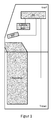
- the FIG. 1 shows a standard ATM having a vault located in its lower area.
- a payer is arranged, which is responsible for the output of money or bills from the vault.
- This payee is controlled by a control unit.
- the control unit is often a conventional PC equipped with appropriate software.
- the conventional PC is usually connected to a card reader, through which the credit card data is read.
- the card reader can read both digital data from the chip of a card and from a magnetic stripe.
- the control unit is connected to an EPP, which is usually designed as a keyboard, or is designed in the form of a touch-sensitive screen.
- EPP which is usually designed as a keyboard, or is designed in the form of a touch-sensitive screen.
- a monitor on which the user guidance takes place. This monitor is also controlled via the PC.
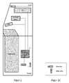
- FIG. 2 An ATM is shown with a security box.
- This security box is located within the vault and has both a camera, which is located in the housing of the ATM and is directed to the user (who stands in front of the device), as well as a camera, which is located within the vault, to take pictures of Payout and the PC to do.
- a microphone is located in the vault, which is also connected to the security box to perform sounds and voice recordings.
- the orientation of the cameras in the FIG. 2 is just an example. Of course, the cameras can also be aligned in the upper area of the ATM.
- the security box is connected between the interfaces of the PC so that it can log the communication between the peripheral devices (EPP, card reader) and record the data.
- the Security Box is able to analyze whether the devices were removed at short notice and re-infected.
- the SB can thus be designed as a USB hub, on the one hand to connect the PC to the SB and on the other hand, the peripherals with the PC. Via the hub function a corresponding reading of the data stream can be achieved.
- an interface to a hard disk within the PC is not shown. However, this can be ensured via appropriate cabling and external elements. These external elements can then be found in the PC and transmit their data via a cable to the Security Box.
Landscapes
- Business, Economics & Management (AREA)
- Accounting & Taxation (AREA)
- Physics & Mathematics (AREA)
- General Physics & Mathematics (AREA)
- Finance (AREA)
- Financial Or Insurance-Related Operations Such As Payment And Settlement (AREA)
Description
- Die Erfindung betrifft ein Verfahren und eine Vorrichtung zur Aufzeichnung von Ereignissen in Selbstbedienungsautomaten.
- Selbstbedienungs- (SB) Automaten weisen oftmals eine Reihe von Komponenten auf, die miteinander zu verbinden sind. In der Regel weisen diese Automaten eine standardisierte PC-Plattform auf, die besonderen Sicherheits-Anforderungen gerecht wird. An dieser PC-Plattform (Motherboard) werden, z.B. über USB-Schnittstellen (Universal Serial Bus) Tastaturen, Auszahleinheiten (Geldnoten-Vereinzelungs-Modul), Kartenlesegeräte, Monitore, und andere Geräte angeschlossen. Auch ist zu beachten, dass in Geldautomaten (ATM) Geldkassetten eingeschoben werden, die zu authentifizieren sind bzw. der Geldautomat hat sich gegenüber der Kassette zu authentifizieren, damit diese ihre Funktionsfähigkeit einschaltet.
- Weiterhin umfassen diese Automaten die Möglichkeit, sich mit einem anderen Computer zu verbinden, damit sich zum Beispiel ein Wartungs-Ingenieur mit seinem Laptop mit dem SB-Automat verbinden kann.
- In der bevorzugten Ausführungsform werden USB oder andere serielle (V24) Verbindungen genutzt, um die Geräte miteinander zu verbinden.
- Es gibt Fälle, in denen eine sicherheitsrelevante Komponente in einem SB-Automat, im Folgenden als Geldautomat bezeichnet, gewechselt werden soll. Eine solche Komponente könnte dabei ein Hardwaremodul wie z.B. eine Geldkassette sein, aber auch eine Softwarekomponente wie z.B. ein Firmware-Update, oder auch periphere Geräte, wie sie oben beschrieben wurden. Entscheidend bei diesem Vorgang ist, dass sich der Geldautomat (PC) gegenüber der neuen Komponente authentisiert bzw. der Geldautomat die Authentizität der Komponente prüfen kann. Nur nach erfolgreicher Authentisierung verrichtet die neue Komponente ihren Dienst.
- Oft werden ATMs durch Manipulation an der Hardware angegriffen. Oder das Personal versucht durch Ausnutzen von Hardwarefehlern Zugriff auf das Gerät zu bekommen, um sich zu bereichern. Da die ATMs während einer Wartung, in der sie heruntergefahren werden und abgeschaltet werden, zeitweise keine Möglichkeit haben die Hardware eigenständig zu überwachen, sind die Geräte insbesondere dann angreifbar und können sich selbst nur schwerlich überprüfen.
- Aufgabe der vorliegenden Erfindung ist die Bereitstellung eines Systems, das unabhängig vom Betrieb des ATM (Automatic Teller Machine) eine weitere Überwachung vornimmt, wobei eine externe Stromzufuhr nicht notwendig ist, um zu protokollieren was momentan vorgenommen wird. Im Falle einer Manipulation oder eines Schadens am ATM kann das Protokoll des Systems weitere Hinweise auf die Täter oder deren Vorgehensweise liefern, so dass ein Nachweis leichter zu führen ist. So kann das System nicht nur den Zustand des Systems protokollieren, sondern auch weitere Informationen wie zum Beispiel Bild- oder Tonmaterial aufnehmen.
- Im Falle eines ATM's besteht diese aus einem Tresor und einer Steuereinheit, die die Geldzufuhr aus dem Tresor steuert. Diese Steuereinheit ist in der Regel der oben beschriebene PC, der die Interaktion mit dem Benutzer vornimmt.
- In der vorliegenden Erfindung kann z.B. über eine Kamera im Tresor ein Zugriff protokolliert werden. Während der Laufzeit könnte das System per Netzwerk oder USB mit dem PC des Geldautomaten verbunden sein und dort über einen Software-Agenten Informationen aufnehmen. Außerdem kann der Status des PCs protokolliert werden.
- Bei vielen Software-Angriffen ist es so, dass versucht wird auf dem PC ein fremdes Betriebssystem zu starten oder zusätzliche Software aufzubringen. Durch die vorliegende Einheit können zusätzliche autonome Einheiten dann solche Angriffe protokollieren und melden. Eine Zusatzsoftware auf dem PC ist dagegen immer angreifbar.
- Bei der Erfindung handelt es sich um einen Selbstbedienungsautomaten umfassend eine Steuereinheit und einen Tresor. Diese Einheit ist zusätzlich gekennzeichnet durch eine Überwachungseinheit, die im Tresor angeordnet ist, und die durch eine selbständige Stromversorgung eine akustische, optische und/oder elektronische Überwachung der Steuereinheit vornimmt. Die Anordnung kann im Tresor so ausgebildet sein, dass eine physikalische Abschottung gegenüber den Geldkassetten innerhalb des Tresors ebenfalls möglich ist. D.h. die Steuereinheit kann in einem weiteren Tresor innerhalb des Tresors angeordnet sein. Somit kann auch eine Person, die berechtigt ist, den Tresor zu öffnen, nicht zwangsweise auch auf die Überwachungseinheit zugreifen. Damit ein Betrieb auch ohne externe Stromversorgung möglich ist, wenn zum Beispiel der Angreifer das Kabel zur Netz-Stromversorgung trennt, ist die Überwachungseinheit mit einer eigenen Stromversorgung versehen, die einen Betrieb für einen gewissen Zeitraum ermöglicht. Dieser Zeitraum kann mehrere Stunden bis Tage betragen. Sollte die externe Stromversorgung ebenfalls keinerlei Leistung mehr bereitstellen, so fährt sich die Überwachungseinheit herunter und speichert die Daten dauerhaft auf einer Festplatte, einem Magnet-Speichertape, Flash-Einheiten oder anderen dauerhaften Speicher-Einheiten. Sobald eine Stromversorgung wiederum gegeben ist, so fährt sich die Überwachungseinheit selbständig hoch. Für eine entsprechende Kühlung wird gesorgt, indem zum Beispiel das Gehäuse des Tresors als Kühloberfläche verwendet wird. Ander Kühlungstechniken sind denkbar.
- So ist es denkbar, dass die eigene Stromversorgung durch Batterien oder Akkumulatoren erfolgt, die sich im Betrieb am Netz wieder aufladen. Es ist auch denkbar, dass die Stromversorgung durch eine Wasserstoffzelle erfolgt. In der Regel handelt es sich dabei um hochwertige Lithium- Akkus, die eine möglichst hohe Leistung bereitstellen, andere Akkutypen sind natürlich denkbar.
- Zur Überwachung weist die Überwachungseinheit eine Kamera und/oder ein Mikrofon auf und ein Speichermedium, das ausgebildet ist, um die Daten von der Kamera und/oder dem Mikrofon dauerhaft aufzuzeichnen. Hierbei ist zu beachten, dass die Kamera möglichst innerhalb des Tresors angeordnet ist und lediglich durch eine Bohrung aus dem Tresor heraus die Überwachung durchführen kann. Die Kamera ist in der Regel so ausgerichtet, dass sie die Steuereinheit vollständig überwachen kann. In der Regel handelt es sich um eine sehr weitwinkelige Kamera, die einen großen Raum überwachen kann und die auch sehr Licht stark ist, um in dunklen Bereichen ebenfalls Aufnahmen durchzuführen. Es ist ebenfalls denkbar, dass eine Vielzahl von Kameras an unterschiedlichen Stellen des Tresors angeordnet ist, die möglichst unauffällig sind, so dass sie für einen Eindringling nicht sofort erkennbar sind. Selbst wenn eine Kamera erkannt werden würde, könnten jedoch andere Kameras weiterhin unentdeckt bleiben. Ebenfalls ist das Mikrofon so angeordnet, dass es Geräusche wirksam aufnehmen kann. Hierfür ist es notwendig, dass Geräusche entsprechend in den Tresor eindringen können. Mit einer entsprechenden Bohrung ist so etwas zu erreichen. Es versteht sich, dass die Einheiten so ausgebildet sind, dass sie in der Regel nur dann Daten aufzeichnen, wenn entsprechende Bewegungen oder unübliche Geräusche detektiert werden können. Hierdurch soll die Datenmenge reduziert werden, die sonst bei einer kontinuierlichen Aufzeichnung entstehen würde. So kann bei der Kamera eine Einstellung vorgenommen werden, dass lediglich eine Aufzeichnung erfolgt, wenn sich bestimmte Bildbereiche verändert haben. Bei dem Mikrofon wird eine Aufzeichnung durchgeführt, wenn der Lautstärkepegel oberhalb eines bestimmten Geräuschpegels ist, der einstellbar ist. Auch das Mikrofon kann in mehrfacher Ausführungsform im Tresor angeordnet sein.
- In einer weiteren möglichen Ausführungsform weist die Überwachungseinheit Mittel auf, um Schnittstellen der Steuereinheit zu überwachen. Die Steuereinheit weist in der Regel viele Schnittstellen auf, wie Schnittstellen zu Festplatten Grafikkarten, Auszahl-System, Monitoren, Tastaturen, die mit unterschiedlichen Standards zum Beispiel USB, VGA, SAS, SATA etc. angesprochen werden. Es versteht sich, dass diese Aufzählung nicht abschließend ist. Vielmehr sollen alle Schnittstellen abgedeckt werden, die durch bekannte PCs bereitgestellt werden, und die dazu dienen Peripheriegeräte anzusteuern. Für die Überprüfung der Schnittstellen kann es unterschiedliche Ansätze geben. Einerseits können Software-Module auf der Steuereinheit angeordnet sein, um während des Betriebes die korrekte Nutzung der Schnittstelle und des Peripheriegerätes zu überprüfen. Diese Software-Module stehen wiederum über eine Schnittstelle, wie zum Beispiel eine USB oder eine Netzwerk-Schnittstelle, mit der Überwachungseinheit in Verbindung, und übermitteln regelmäßig Informationen über die Peripheriegeräte, den Zustand der Schnittstelle und den Zustand des Steuerungssystems. Andererseits können auch mechanische Überwachungssysteme eingesetzt werden, die auf Kabeln aufgesetzt werden bzw. zwischen Kabel zwischengeschaltet werden. Sollte zum Beispiel ein Kabel abgezogen werden bzw. ein Peripheriegerät von der Steuereinheit gelöst werden, so kann über mechanische Schalter oder elektronische Kontakte ein solches Lösen erkannt werden, auch wenn das Steuerungssystem nicht angeschaltet ist. So ist es zum Beispiel denkbar, dass die Stecker einer Festplatte auf beiden Seiten mit entsprechenden Modulen zur Überwachung versehen sind, die erkennen, ob eine Festplatte gelöst wurde oder nicht. Das Gleiche kann für USB oder eine Schnittstelle verwendet werden. Diese Einheiten können ebenfalls dazu genutzt werden den Datenverkehr auf den entsprechenden Schnittstellen zu analysieren und gegebenenfalls um diesen Datenverkehr mit zuschneiden. Die Übertragung der Daten von den Überwachungseinheiten, die auf die Schnittstellen gesteckt werden, kann kabellos erfolgen oder ebenfalls über ein Netzwerk. Bei der kabellosen Übertragung können zum Beispiel Bluetooth oder WLAN verwendet werden.
- Durch diesen Ansatz kann eine Überwachung des Austauschs einer Speichereinheit in der Steuereinheit erfolgen, insbesondere einer Festplatte. Hierbei sind Kontakteinheiten vorhanden, die einen Austausch erkennen. Die Kontaktstecker sind auf einem Festplattenkabel angeordnet, so dass erkannt wird, wenn die Speichereinheit ausgetauscht wird, oder sich der Inhalt der Festplatte verändert hat. Beim letztgenannten Ansatz, kann der Stecker in regelmäßigen Abständen einen Hashwert von der Festplatte speichern bzw. erstellen, um zu überprüfen, ob sich der Hashwert dann verändert hat. Insbesondere ist dies möglich für bestimmte Speicherbereiche der Festplatte, auf denen codierte Informationen abgelegt sind. Bei einem Starten einer Festplatte fragt die Stecker-Einheit diese entsprechenden Daten ab, man kann auch von einer Signatur sprechen, und kann dann eine Warnmeldung an die Überprüfungseinheit senden, falls sich die Daten der Festplatte verändert haben bzw. die Festplatte ausgetauscht wurde und nicht mehr diesen Signaturbereich aufweist. Der Stecker kann ausgebildet sein, dass er bei einem Herunterfahren die Signatur überprüft und gegebenenfalls einen Hashwert der Festplatte auf dieser hinterlegt. Es ist auch denkbar dass ein Hashwert für bestimmte Datenbereiche erstellt wird und nicht für die gesamte Festplatte. Beim Starten der Festplatte wird dieser Bereich geprüft, um dann gegebenenfalls eine Warnmeldung zu erzeugen oder sogar die Festplatte zu deaktivieren bzw. eine Verbindung zur Steuereinheit zu unterbinden.
- Auch kann eine Überwachung von Komponenten, die mit der Steuereinheit verbunden sind, erfolgen, insbesondere von Auszahler, Tastatur und/oder Monitor. Die Überwachungseinheit weist dabei Mittel auf, um ein Mitschneiden von Schnittstellen zu den Komponenten durchzuführen. Die Überwachungseinheit weist eine eigene physikalische Verbindung zum Auszahler auf, durch den eine Überwachung erfolgt. So ist es möglich Serviceschnittstellen zum Auszahler oder anderen Geräten mitzuschneiden. Beim Auszahler ist z.B. zusätzlich zur USB-Verbindung noch eine serielle Schnittstelle für Servicezwecke vorhanden. Ein Deaktivieren der Verschlüsselung oder ein Kompromittieren des Gerätes durch Fremdsoftware kann dadurch detektiert werden, auch wenn der Auszahler nicht mehr mit dem ATM-PC/Steuereinheit verbunden ist.
- Es ist natürlich auch möglich, dass die Überwachungseinheit bei einem möglichen Angriff, der in ein Angriffsmuster passt, die Steuereinheit oder bestimmte Komponenten dauerhaft deaktiviert. So ist es möglich den Auszahler abzuschalten, so dass er nicht erneut konfiguriert werden kann. Auch ist es denkbar ein Booten der Steuereinheit zu unterbinden. Ferner können Komponenten, wie Netzteile oder andere Komponenten deaktiviert werden, so dass ein erneutes Starten nicht mehr möglich ist.
-
-
Figur 1 zeigt einen ATM in seinem grundsätzlichen Aufbau mit einer Steuereinheit und einem Tresor. -
Figur 2 zeigt einen ATM mit der Überwachungseinheit, die im Tresor angeordnet ist. -
Figur 2c zeigt die Symbole für Kamera und Mikrofon. - Die
Figur 1 zeigt einen Standard ATM, der einen Tresor aufweist, der in seinem unteren Bereich angeordnet ist. Innerhalb des Tresors ist ein Auszahler angeordnet, der für die Ausgabe des Geldes bzw. der Geldscheine aus dem Tresor zuständig ist. Dieser Auszahler wird von einer Steuereinheit angesteuert. Wie bereits oben ausgeführt wurde, ist die Steuereinheit oftmals ein herkömmlicher PC, der mit einer entsprechenden Software ausgestattet ist. Der herkömmliche PC ist in der Regel mit einem Kartenlesegerät verbunden, durch das die Daten der Kreditkarten eingelesen wird. Das Kartenlesegerät kann sowohl digitale Daten vom Chip einer Karte lesen als auch von einem Magnetstreifen. Weiterhin ist die Steuereinheit mit einem EPP verbunden, das in der Regel als Tastatur ausgebildet ist, oder in Form eines berührungsempfindlichen Bildschirms ausgebildet ist. Über dieses Eingabegerät werden entsprechende Geheimzahlen oder Pins eingegeben oder ein Benutzerdialog geführt. Nicht dargestellt ist ein Monitor, auf dem die Benutzerführung erfolgt. Dieser Monitor wird ebenfalls über den PC gesteuert. - In der
Figur 2 ist ein ATM mit einer Security Box dargestellt. Diese Security Box ist innerhalb des Tresors angeordnet und weist sowohl eine Kamera auf, die im Gehäuse des ATM angeordnet ist und zum Benutzer gerichtet ist (der vor dem Gerät steht), als auch eine Kamera, die innerhalb des Tresors angeordnet ist, um Aufnahmen vom Auszahler und dem PC zu machen. Weiterhin ist ein Mikrofon im Tresor angeordnet, das ebenfalls mit der Security Box verbunden ist, um Geräusche und Sprachaufnahmen durchzuführen. Die Ausrichtung der Kameras in derFigur 2 ist lediglich beispielhaft. Die Kameras können natürlich auch in den oberen Bereich des ATM ausgerichtet sein. Ferner ist die Security Box zwischen die Schnittstellen des PCs geschaltet, so dass sie die Kommunikation zwischen den Peripheriegeräten (EPP, Kartenleser) loggen kann und die Daten aufzeichnen kann. Auch ist die Security Box in der Lage zu analysieren, ob die Geräte kurzfristig entfernt wurden und erneut angesteckt wurden. Hierzu gibt es entsprechende Schnittstellen an der Security Box, in die die Geräte einzustecken sind. Die SB kann somit als USB Hub ausgebildet sein, um einerseits den PC mit der SB zu verbinden und andererseits die Peripheriegeräte mit dem PC. Über die Hub-Funktion kann ein entsprechendes Mitlesen des Datenstroms erreicht werden. Nicht dargestellt ist eine Schnittstelle zu einer Festplatte innerhalb des PCs. Dies kann jedoch über eine entsprechende Verkabelung und externe Elemente sichergestellt werden. Diese externen Elemente finden sich dann im PC und übertragen ihre Daten über ein Kabel an die Security Box.
Claims (10)
- Selbstbedienungsautomat umfassend eine Steuereinheit und einen Tresor, gekennzeichnet durch
eine Überwachungseinheit, die im Tresor angeordnet ist, und die durch eine selbständige Stromversorgung eine akustische, optische und/oder elektronische Überwachung der Steuereinheit vornimmt. - Selbstbedienungsautomat nach dem vorhergehenden Anspruch, dadurch gekennzeichnet, dass die selbständige Stromversorgung auch ohne Netzstrom arbeitet und durch eine Batterie oder Wasserstoffzelle versorgt wird.
- Selbstbedienungsautomat nach einem oder mehreren der vorhergehenden Ansprüche, wobei die Überwachungseinheit eine Kamera und/oder ein Mikrofon aufweist und ein Speichermedium, das ausgebildet ist, um die Daten von der Kamera und/oder dem Mikrofon dauerhaft aufzuzeichnen.
- Selbstbedienungsautomat nach einem oder mehreren der vorhergehenden Ansprüche, wobei die Überwachungseinheit Schnittstellen der Steuereinheit auf Treiberbasis der Steuereinheit oder mechanisch durch Zwischenstecker, die auf den Schnittstellen angeordnet sind, überwacht.
- Selbstbedienungsautomat nach einem oder mehreren der vorhergehenden Ansprüche, wobei zur Überwachung des Austauschs einer Speichereinheit, insbesondere einer Festplatte in der Steuereinheit, Kontakteinheiten vorhanden sind, die einen Austausch erkennen.
- Selbstbedienungsautomat nach einem oder mehreren der vorhergehenden Ansprüche, wobei ein Kontaktstecker auf einem Festplattenkabel angeordnet ist, so dass erkennbar ist, wenn die Speichereinheit ausgetauscht wurde, oder sich der Inhalt der Festplatte verändert hat.
- Selbstbedienungsautomat nach einem oder mehreren der vorhergehenden Ansprüche, wobei ein Software-Agent auf der Steuereinheit läuft, der Veränderungen protokolliert und an die Überwachungseinheit übermittelt.
- Selbstbedienungsautomat nach einem oder mehreren der vorhergehenden Ansprüche, wobei eine Überwachung von Komponenten, die mit der Steuereinheit verbunden sind, erfolgt, insbesondere von Auszahler, Tastatur und/oder Monitor.
- Selbstbedienungsautomat nach dem vorhergehenden Anspruch, wobei die Überwachungseinheit Mittel aufweist, um ein Mitschneiden von Schnittstellen der Komponenten durchzuführen.
- Selbstbedienungsautomat nach den vorhergehenden zwei Ansprüchen, wobei die Überwachungseinheit eine eigene physikalische Verbindung zum Auszahler aufweist, durch die eine Überwachung erfolgt.
Priority Applications (1)
| Application Number | Priority Date | Filing Date | Title |
|---|---|---|---|
| EP13174518.4A EP2821976B1 (de) | 2013-07-01 | 2013-07-01 | Verfahren und Vorrichtung zur Aufzeichnung von Ereignissen in Selbstbedienungsautomaten |
Applications Claiming Priority (1)
| Application Number | Priority Date | Filing Date | Title |
|---|---|---|---|
| EP13174518.4A EP2821976B1 (de) | 2013-07-01 | 2013-07-01 | Verfahren und Vorrichtung zur Aufzeichnung von Ereignissen in Selbstbedienungsautomaten |
Publications (2)
| Publication Number | Publication Date |
|---|---|
| EP2821976A1 true EP2821976A1 (de) | 2015-01-07 |
| EP2821976B1 EP2821976B1 (de) | 2020-04-29 |
Family
ID=48745754
Family Applications (1)
| Application Number | Title | Priority Date | Filing Date |
|---|---|---|---|
| EP13174518.4A Active EP2821976B1 (de) | 2013-07-01 | 2013-07-01 | Verfahren und Vorrichtung zur Aufzeichnung von Ereignissen in Selbstbedienungsautomaten |
Country Status (1)
| Country | Link |
|---|---|
| EP (1) | EP2821976B1 (de) |
Cited By (1)
| Publication number | Priority date | Publication date | Assignee | Title |
|---|---|---|---|---|
| WO2020008190A1 (en) * | 2018-07-03 | 2020-01-09 | Tcs John Huxley Europe Limited | Casino apparatus |
Citations (4)
| Publication number | Priority date | Publication date | Assignee | Title |
|---|---|---|---|---|
| US5253167A (en) * | 1989-06-15 | 1993-10-12 | Hitachi, Ltd. | Remote maintenance/supervisory system and method for automated teller machines |
| US20020000913A1 (en) * | 2000-05-18 | 2002-01-03 | Yoshiaki Hamamoto | Monitoring device for security in automatic teller machine |
| DE102008013634A1 (de) * | 2008-03-11 | 2009-09-17 | Wincor Nixdorf International Gmbh | Verfahren und Vorrichtung zur Abwehr von Angriffen auf Systeme mit einer Plug & Play Funktion |
| DE102008049599A1 (de) * | 2008-09-30 | 2010-04-01 | Wincor Nixdorf International Gmbh | Verfahren und Vorrichtung zur Erkennung von Angriffen auf einen Selbstbedienungsautomat |
Family Cites Families (5)
| Publication number | Priority date | Publication date | Assignee | Title |
|---|---|---|---|---|
| JP2536719B2 (ja) * | 1993-05-14 | 1996-09-18 | 日本電気株式会社 | 現金処理機チェック装置 |
| JPH11213223A (ja) * | 1998-01-26 | 1999-08-06 | Sanyo Electric Co Ltd | 自動販売機 |
| DE19811433A1 (de) * | 1998-02-20 | 1999-08-26 | Maku Informationstechnik Gmbh | Videoüberwachungseinrichtung |
| US7502068B2 (en) * | 2004-06-22 | 2009-03-10 | International Business Machines Corporation | Sensor for imaging inside equipment |
| US7183915B2 (en) * | 2004-08-05 | 2007-02-27 | 3Si Security Systems, Inc. | Wireless ATM security system |
-
2013
- 2013-07-01 EP EP13174518.4A patent/EP2821976B1/de active Active
Patent Citations (4)
| Publication number | Priority date | Publication date | Assignee | Title |
|---|---|---|---|---|
| US5253167A (en) * | 1989-06-15 | 1993-10-12 | Hitachi, Ltd. | Remote maintenance/supervisory system and method for automated teller machines |
| US20020000913A1 (en) * | 2000-05-18 | 2002-01-03 | Yoshiaki Hamamoto | Monitoring device for security in automatic teller machine |
| DE102008013634A1 (de) * | 2008-03-11 | 2009-09-17 | Wincor Nixdorf International Gmbh | Verfahren und Vorrichtung zur Abwehr von Angriffen auf Systeme mit einer Plug & Play Funktion |
| DE102008049599A1 (de) * | 2008-09-30 | 2010-04-01 | Wincor Nixdorf International Gmbh | Verfahren und Vorrichtung zur Erkennung von Angriffen auf einen Selbstbedienungsautomat |
Cited By (2)
| Publication number | Priority date | Publication date | Assignee | Title |
|---|---|---|---|---|
| WO2020008190A1 (en) * | 2018-07-03 | 2020-01-09 | Tcs John Huxley Europe Limited | Casino apparatus |
| US11657675B2 (en) | 2018-07-03 | 2023-05-23 | Tcs John Huxley Europe Limited | Casino apparatus |
Also Published As
| Publication number | Publication date |
|---|---|
| EP2821976B1 (de) | 2020-04-29 |
Similar Documents
| Publication | Publication Date | Title |
|---|---|---|
| DE112008000135B4 (de) | Andock-Sicherheitssystem für tragbare Rechensysteme | |
| EP2367128B1 (de) | Verfahren und Vorrichtung zur elektronischen Signatur | |
| DE102013003071A1 (de) | Verifizierungs-(Sperrungs)-Verfahren mit Authentifizierungschip zur Identifizierung eines Chips auf Systemebene | |
| EP2668607A1 (de) | Verfahren zur überwachung eines tamperschutzes sowie überwachungssystem für ein feldgerät mit tamperschutz | |
| DE102015106741B4 (de) | Zusammenbringen von vorrichtung und zubehör | |
| DE102007033346A1 (de) | Verfahren und Vorrichtung zur Administration von Computern | |
| DE102007005638A1 (de) | Verfahren zur Autorisierung des Zugriffs auf mindestens eine Automatisierungskompente einer technischen Anlage | |
| DE102008049599A1 (de) | Verfahren und Vorrichtung zur Erkennung von Angriffen auf einen Selbstbedienungsautomat | |
| DE102010000482A1 (de) | Methode und Verfahren für PIN-Eingaben bei konsistentem Software-Stack auf Geldautomaten | |
| EP0570924A2 (de) | Verfahren zur Authentifizierung eines Systemteiles durch einen anderen Systemteil in einem Informationsübertragungssystem bestehend aus einem Terminal und einer tragbaren Datenträgeranordnung | |
| EP2257903B1 (de) | Verfahren und vorrichtung zur abwehr von angriffen auf systeme mit einer plug&play funktion | |
| EP2821976B1 (de) | Verfahren und Vorrichtung zur Aufzeichnung von Ereignissen in Selbstbedienungsautomaten | |
| EP3347880B1 (de) | Verfahren und vorrichtung zur bestimmung der integrität einer kartenleseeinrichtung und ein damit ausgestattetes selbstbedienungsterminal | |
| DE3820868A1 (de) | System zum abruf von spielgeraetedaten | |
| EP2455925B1 (de) | Verfahren und Vorrichtung zur Abwehr von Manipulationsversuchen an einem Kamera-System | |
| EP2930701B1 (de) | Vorrichtung zur Handhabung von Wertscheinen mit modularem Aufbau | |
| DE10035598A1 (de) | Datenträger mit einem Datenspeicher | |
| DE202004008380U1 (de) | Sicherer Kartenleser | |
| DE19718173C2 (de) | Einrichtung zum Schutz eines Rechnersystems gegen unerlaubtes Ziehen einer Hardware-Komponente | |
| DE102005045816B4 (de) | Verfahren, Softwareprogrammprodukt und Vorrichtung zur Herstellung von Sicherheitsdokumenten | |
| DE10259270A1 (de) | Personalisierung von Sicherheitsmoduln | |
| DE102019004274A1 (de) | Kommunikationssystem für einen Spiel- oder Unterhaltungsautomaten | |
| DE102016113844B4 (de) | Schalteranordnung für ein elektronisches Gerät und Computersystem | |
| EP2752729B1 (de) | Revisionssystem zur Revision einer technischen Anlage | |
| DE102006044328A1 (de) | Verfahren und Anordnung zum Feststellen einer unbefugten Manipulation einer elektrischen Einrichtung |
Legal Events
| Date | Code | Title | Description |
|---|---|---|---|
| PUAI | Public reference made under article 153(3) epc to a published international application that has entered the european phase |
Free format text: ORIGINAL CODE: 0009012 |
|
| 17P | Request for examination filed |
Effective date: 20130701 |
|
| AK | Designated contracting states |
Kind code of ref document: A1 Designated state(s): AL AT BE BG CH CY CZ DE DK EE ES FI FR GB GR HR HU IE IS IT LI LT LU LV MC MK MT NL NO PL PT RO RS SE SI SK SM TR |
|
| AX | Request for extension of the european patent |
Extension state: BA ME |
|
| R17P | Request for examination filed (corrected) |
Effective date: 20150630 |
|
| RBV | Designated contracting states (corrected) |
Designated state(s): AL AT BE BG CH CY CZ DE DK EE ES FI FR GB GR HR HU IE IS IT LI LT LU LV MC MK MT NL NO PL PT RO RS SE SI SK SM TR |
|
| 17Q | First examination report despatched |
Effective date: 20160311 |
|
| GRAP | Despatch of communication of intention to grant a patent |
Free format text: ORIGINAL CODE: EPIDOSNIGR1 |
|
| STAA | Information on the status of an ep patent application or granted ep patent |
Free format text: STATUS: GRANT OF PATENT IS INTENDED |
|
| INTG | Intention to grant announced |
Effective date: 20191121 |
|
| GRAS | Grant fee paid |
Free format text: ORIGINAL CODE: EPIDOSNIGR3 |
|
| GRAA | (expected) grant |
Free format text: ORIGINAL CODE: 0009210 |
|
| STAA | Information on the status of an ep patent application or granted ep patent |
Free format text: STATUS: THE PATENT HAS BEEN GRANTED |
|
| AK | Designated contracting states |
Kind code of ref document: B1 Designated state(s): AL AT BE BG CH CY CZ DE DK EE ES FI FR GB GR HR HU IE IS IT LI LT LU LV MC MK MT NL NO PL PT RO RS SE SI SK SM TR |
|
| REG | Reference to a national code |
Ref country code: GB Ref legal event code: FG4D Free format text: NOT ENGLISH |
|
| REG | Reference to a national code |
Ref country code: CH Ref legal event code: EP |
|
| REG | Reference to a national code |
Ref country code: AT Ref legal event code: REF Ref document number: 1264470 Country of ref document: AT Kind code of ref document: T Effective date: 20200515 |
|
| REG | Reference to a national code |
Ref country code: DE Ref legal event code: R096 Ref document number: 502013014638 Country of ref document: DE |
|
| REG | Reference to a national code |
Ref country code: IE Ref legal event code: FG4D Free format text: LANGUAGE OF EP DOCUMENT: GERMAN |
|
| REG | Reference to a national code |
Ref country code: NL Ref legal event code: MP Effective date: 20200429 |
|
| REG | Reference to a national code |
Ref country code: LT Ref legal event code: MG4D |
|
| PG25 | Lapsed in a contracting state [announced via postgrant information from national office to epo] |
Ref country code: NO Free format text: LAPSE BECAUSE OF FAILURE TO SUBMIT A TRANSLATION OF THE DESCRIPTION OR TO PAY THE FEE WITHIN THE PRESCRIBED TIME-LIMIT Effective date: 20200729 Ref country code: IS Free format text: LAPSE BECAUSE OF FAILURE TO SUBMIT A TRANSLATION OF THE DESCRIPTION OR TO PAY THE FEE WITHIN THE PRESCRIBED TIME-LIMIT Effective date: 20200829 Ref country code: PT Free format text: LAPSE BECAUSE OF FAILURE TO SUBMIT A TRANSLATION OF THE DESCRIPTION OR TO PAY THE FEE WITHIN THE PRESCRIBED TIME-LIMIT Effective date: 20200831 Ref country code: GR Free format text: LAPSE BECAUSE OF FAILURE TO SUBMIT A TRANSLATION OF THE DESCRIPTION OR TO PAY THE FEE WITHIN THE PRESCRIBED TIME-LIMIT Effective date: 20200730 Ref country code: FI Free format text: LAPSE BECAUSE OF FAILURE TO SUBMIT A TRANSLATION OF THE DESCRIPTION OR TO PAY THE FEE WITHIN THE PRESCRIBED TIME-LIMIT Effective date: 20200429 Ref country code: SE Free format text: LAPSE BECAUSE OF FAILURE TO SUBMIT A TRANSLATION OF THE DESCRIPTION OR TO PAY THE FEE WITHIN THE PRESCRIBED TIME-LIMIT Effective date: 20200429 Ref country code: LT Free format text: LAPSE BECAUSE OF FAILURE TO SUBMIT A TRANSLATION OF THE DESCRIPTION OR TO PAY THE FEE WITHIN THE PRESCRIBED TIME-LIMIT Effective date: 20200429 |
|
| PG25 | Lapsed in a contracting state [announced via postgrant information from national office to epo] |
Ref country code: HR Free format text: LAPSE BECAUSE OF FAILURE TO SUBMIT A TRANSLATION OF THE DESCRIPTION OR TO PAY THE FEE WITHIN THE PRESCRIBED TIME-LIMIT Effective date: 20200429 Ref country code: BG Free format text: LAPSE BECAUSE OF FAILURE TO SUBMIT A TRANSLATION OF THE DESCRIPTION OR TO PAY THE FEE WITHIN THE PRESCRIBED TIME-LIMIT Effective date: 20200729 Ref country code: RS Free format text: LAPSE BECAUSE OF FAILURE TO SUBMIT A TRANSLATION OF THE DESCRIPTION OR TO PAY THE FEE WITHIN THE PRESCRIBED TIME-LIMIT Effective date: 20200429 Ref country code: LV Free format text: LAPSE BECAUSE OF FAILURE TO SUBMIT A TRANSLATION OF THE DESCRIPTION OR TO PAY THE FEE WITHIN THE PRESCRIBED TIME-LIMIT Effective date: 20200429 |
|
| PG25 | Lapsed in a contracting state [announced via postgrant information from national office to epo] |
Ref country code: AL Free format text: LAPSE BECAUSE OF FAILURE TO SUBMIT A TRANSLATION OF THE DESCRIPTION OR TO PAY THE FEE WITHIN THE PRESCRIBED TIME-LIMIT Effective date: 20200429 Ref country code: NL Free format text: LAPSE BECAUSE OF FAILURE TO SUBMIT A TRANSLATION OF THE DESCRIPTION OR TO PAY THE FEE WITHIN THE PRESCRIBED TIME-LIMIT Effective date: 20200429 |
|
| PG25 | Lapsed in a contracting state [announced via postgrant information from national office to epo] |
Ref country code: ES Free format text: LAPSE BECAUSE OF FAILURE TO SUBMIT A TRANSLATION OF THE DESCRIPTION OR TO PAY THE FEE WITHIN THE PRESCRIBED TIME-LIMIT Effective date: 20200429 Ref country code: DK Free format text: LAPSE BECAUSE OF FAILURE TO SUBMIT A TRANSLATION OF THE DESCRIPTION OR TO PAY THE FEE WITHIN THE PRESCRIBED TIME-LIMIT Effective date: 20200429 Ref country code: EE Free format text: LAPSE BECAUSE OF FAILURE TO SUBMIT A TRANSLATION OF THE DESCRIPTION OR TO PAY THE FEE WITHIN THE PRESCRIBED TIME-LIMIT Effective date: 20200429 Ref country code: SM Free format text: LAPSE BECAUSE OF FAILURE TO SUBMIT A TRANSLATION OF THE DESCRIPTION OR TO PAY THE FEE WITHIN THE PRESCRIBED TIME-LIMIT Effective date: 20200429 Ref country code: IT Free format text: LAPSE BECAUSE OF FAILURE TO SUBMIT A TRANSLATION OF THE DESCRIPTION OR TO PAY THE FEE WITHIN THE PRESCRIBED TIME-LIMIT Effective date: 20200429 Ref country code: RO Free format text: LAPSE BECAUSE OF FAILURE TO SUBMIT A TRANSLATION OF THE DESCRIPTION OR TO PAY THE FEE WITHIN THE PRESCRIBED TIME-LIMIT Effective date: 20200429 Ref country code: CZ Free format text: LAPSE BECAUSE OF FAILURE TO SUBMIT A TRANSLATION OF THE DESCRIPTION OR TO PAY THE FEE WITHIN THE PRESCRIBED TIME-LIMIT Effective date: 20200429 |
|
| REG | Reference to a national code |
Ref country code: DE Ref legal event code: R097 Ref document number: 502013014638 Country of ref document: DE |
|
| PG25 | Lapsed in a contracting state [announced via postgrant information from national office to epo] |
Ref country code: PL Free format text: LAPSE BECAUSE OF FAILURE TO SUBMIT A TRANSLATION OF THE DESCRIPTION OR TO PAY THE FEE WITHIN THE PRESCRIBED TIME-LIMIT Effective date: 20200429 Ref country code: SK Free format text: LAPSE BECAUSE OF FAILURE TO SUBMIT A TRANSLATION OF THE DESCRIPTION OR TO PAY THE FEE WITHIN THE PRESCRIBED TIME-LIMIT Effective date: 20200429 Ref country code: MC Free format text: LAPSE BECAUSE OF FAILURE TO SUBMIT A TRANSLATION OF THE DESCRIPTION OR TO PAY THE FEE WITHIN THE PRESCRIBED TIME-LIMIT Effective date: 20200429 |
|
| REG | Reference to a national code |
Ref country code: CH Ref legal event code: PL |
|
| PLBE | No opposition filed within time limit |
Free format text: ORIGINAL CODE: 0009261 |
|
| STAA | Information on the status of an ep patent application or granted ep patent |
Free format text: STATUS: NO OPPOSITION FILED WITHIN TIME LIMIT |
|
| 26N | No opposition filed |
Effective date: 20210201 |
|
| REG | Reference to a national code |
Ref country code: BE Ref legal event code: MM Effective date: 20200731 |
|
| PG25 | Lapsed in a contracting state [announced via postgrant information from national office to epo] |
Ref country code: CH Free format text: LAPSE BECAUSE OF NON-PAYMENT OF DUE FEES Effective date: 20200731 Ref country code: IE Free format text: LAPSE BECAUSE OF NON-PAYMENT OF DUE FEES Effective date: 20200701 Ref country code: LI Free format text: LAPSE BECAUSE OF NON-PAYMENT OF DUE FEES Effective date: 20200731 Ref country code: LU Free format text: LAPSE BECAUSE OF NON-PAYMENT OF DUE FEES Effective date: 20200701 |
|
| PG25 | Lapsed in a contracting state [announced via postgrant information from national office to epo] |
Ref country code: SI Free format text: LAPSE BECAUSE OF FAILURE TO SUBMIT A TRANSLATION OF THE DESCRIPTION OR TO PAY THE FEE WITHIN THE PRESCRIBED TIME-LIMIT Effective date: 20200429 Ref country code: BE Free format text: LAPSE BECAUSE OF NON-PAYMENT OF DUE FEES Effective date: 20200731 |
|
| REG | Reference to a national code |
Ref country code: AT Ref legal event code: MM01 Ref document number: 1264470 Country of ref document: AT Kind code of ref document: T Effective date: 20200701 |
|
| PG25 | Lapsed in a contracting state [announced via postgrant information from national office to epo] |
Ref country code: AT Free format text: LAPSE BECAUSE OF NON-PAYMENT OF DUE FEES Effective date: 20200701 |
|
| PG25 | Lapsed in a contracting state [announced via postgrant information from national office to epo] |
Ref country code: TR Free format text: LAPSE BECAUSE OF FAILURE TO SUBMIT A TRANSLATION OF THE DESCRIPTION OR TO PAY THE FEE WITHIN THE PRESCRIBED TIME-LIMIT Effective date: 20200429 Ref country code: MT Free format text: LAPSE BECAUSE OF FAILURE TO SUBMIT A TRANSLATION OF THE DESCRIPTION OR TO PAY THE FEE WITHIN THE PRESCRIBED TIME-LIMIT Effective date: 20200429 Ref country code: CY Free format text: LAPSE BECAUSE OF FAILURE TO SUBMIT A TRANSLATION OF THE DESCRIPTION OR TO PAY THE FEE WITHIN THE PRESCRIBED TIME-LIMIT Effective date: 20200429 |
|
| REG | Reference to a national code |
Ref country code: FR Ref legal event code: PLFP Year of fee payment: 10 |
|
| PG25 | Lapsed in a contracting state [announced via postgrant information from national office to epo] |
Ref country code: MK Free format text: LAPSE BECAUSE OF FAILURE TO SUBMIT A TRANSLATION OF THE DESCRIPTION OR TO PAY THE FEE WITHIN THE PRESCRIBED TIME-LIMIT Effective date: 20200429 |
|
| REG | Reference to a national code |
Ref country code: GB Ref legal event code: 732E Free format text: REGISTERED BETWEEN 20230323 AND 20230329 |
|
| REG | Reference to a national code |
Ref country code: GB Ref legal event code: 732E Free format text: REGISTERED BETWEEN 20230525 AND 20230601 |
|
| REG | Reference to a national code |
Ref country code: DE Ref legal event code: R081 Ref document number: 502013014638 Country of ref document: DE Owner name: DIEBOLD NIXDORF SYSTEMS GMBH, DE Free format text: FORMER OWNER: WINCOR NIXDORF INTERNATIONAL GMBH, 33106 PADERBORN, DE |
|
| PGFP | Annual fee paid to national office [announced via postgrant information from national office to epo] |
Ref country code: GB Payment date: 20250619 Year of fee payment: 13 |
|
| PGFP | Annual fee paid to national office [announced via postgrant information from national office to epo] |
Ref country code: FR Payment date: 20250620 Year of fee payment: 13 |
|
| PGFP | Annual fee paid to national office [announced via postgrant information from national office to epo] |
Ref country code: DE Payment date: 20250620 Year of fee payment: 13 |