EP2821838A1 - Autofocus mechanism - Google Patents
Autofocus mechanism Download PDFInfo
- Publication number
- EP2821838A1 EP2821838A1 EP14174938.2A EP14174938A EP2821838A1 EP 2821838 A1 EP2821838 A1 EP 2821838A1 EP 14174938 A EP14174938 A EP 14174938A EP 2821838 A1 EP2821838 A1 EP 2821838A1
- Authority
- EP
- European Patent Office
- Prior art keywords
- signal
- amplified
- focal position
- amplified signal
- voltage value
- Prior art date
- Legal status (The legal status is an assumption and is not a legal conclusion. Google has not performed a legal analysis and makes no representation as to the accuracy of the status listed.)
- Granted
Links
Images






Classifications
-
- G—PHYSICS
- G02—OPTICS
- G02B—OPTICAL ELEMENTS, SYSTEMS OR APPARATUS
- G02B7/00—Mountings, adjusting means, or light-tight connections, for optical elements
- G02B7/28—Systems for automatic generation of focusing signals
-
- G—PHYSICS
- G02—OPTICS
- G02B—OPTICAL ELEMENTS, SYSTEMS OR APPARATUS
- G02B21/00—Microscopes
- G02B21/24—Base structure
- G02B21/241—Devices for focusing
- G02B21/245—Devices for focusing using auxiliary sources, detectors
- G02B21/247—Differential detectors
-
- G—PHYSICS
- G02—OPTICS
- G02B—OPTICAL ELEMENTS, SYSTEMS OR APPARATUS
- G02B7/00—Mountings, adjusting means, or light-tight connections, for optical elements
- G02B7/28—Systems for automatic generation of focusing signals
- G02B7/36—Systems for automatic generation of focusing signals using image sharpness techniques, e.g. image processing techniques for generating autofocus signals
- G02B7/38—Systems for automatic generation of focusing signals using image sharpness techniques, e.g. image processing techniques for generating autofocus signals measured at different points on the optical axis, e.g. focussing on two or more planes and comparing image data
-
- G—PHYSICS
- G03—PHOTOGRAPHY; CINEMATOGRAPHY; ANALOGOUS TECHNIQUES USING WAVES OTHER THAN OPTICAL WAVES; ELECTROGRAPHY; HOLOGRAPHY
- G03B—APPARATUS OR ARRANGEMENTS FOR TAKING PHOTOGRAPHS OR FOR PROJECTING OR VIEWING THEM; APPARATUS OR ARRANGEMENTS EMPLOYING ANALOGOUS TECHNIQUES USING WAVES OTHER THAN OPTICAL WAVES; ACCESSORIES THEREFOR
- G03B13/00—Viewfinders; Focusing aids for cameras; Means for focusing for cameras; Autofocus systems for cameras
-
- G—PHYSICS
- G03—PHOTOGRAPHY; CINEMATOGRAPHY; ANALOGOUS TECHNIQUES USING WAVES OTHER THAN OPTICAL WAVES; ELECTROGRAPHY; HOLOGRAPHY
- G03B—APPARATUS OR ARRANGEMENTS FOR TAKING PHOTOGRAPHS OR FOR PROJECTING OR VIEWING THEM; APPARATUS OR ARRANGEMENTS EMPLOYING ANALOGOUS TECHNIQUES USING WAVES OTHER THAN OPTICAL WAVES; ACCESSORIES THEREFOR
- G03B13/00—Viewfinders; Focusing aids for cameras; Means for focusing for cameras; Autofocus systems for cameras
- G03B13/32—Means for focusing
- G03B13/34—Power focusing
- G03B13/36—Autofocus systems
-
- G—PHYSICS
- G03—PHOTOGRAPHY; CINEMATOGRAPHY; ANALOGOUS TECHNIQUES USING WAVES OTHER THAN OPTICAL WAVES; ELECTROGRAPHY; HOLOGRAPHY
- G03B—APPARATUS OR ARRANGEMENTS FOR TAKING PHOTOGRAPHS OR FOR PROJECTING OR VIEWING THEM; APPARATUS OR ARRANGEMENTS EMPLOYING ANALOGOUS TECHNIQUES USING WAVES OTHER THAN OPTICAL WAVES; ACCESSORIES THEREFOR
- G03B3/00—Focusing arrangements of general interest for cameras, projectors or printers
Definitions
- the present invention relates to an autofocus mechanism adjusting a focal position with respect to a work piece.
- an autofocus mechanism used in a measurement device is known (see Japanese Patent Laid-open Publication No. H07-105547 ).
- the autofocus mechanism uses a method emitting light at a work piece and identifying a focal position based on light reflected by the work piece. Specifically, the reflected light received by a photodiode is converted to an electric signal. Then, a low-strength electric signal is amplified by a high-magnification amplifier, while a high-strength electric signal is amplified by a low-magnification amplifier. Then, the focal position is identified based on the amplified electric signals.
- the present disclosure provides an autofocus mechanism with improved accuracy in identifying a focal position.
- An autofocus mechanism includes a light source emitting light through an objective lens at a work piece; a first detector detecting a first portion of light reflected by the work piece and generating a first signal; a second detector detecting a second portion of the reflected light and generating a second signal; a first amplifier amplifying a voltage value of the first signal by a first amplification rate and generating a first amplified signal; a second amplifier amplifying the voltage value of the first signal by a second amplification rate greater than the first amplification rate and generating a second amplified signal; a third amplifier amplifying the voltage value of the second signal by a third amplification rate and generating a third amplified signal; a fourth amplifier amplifying the voltage value of the second signal by a fourth amplification rate greater than the third amplification rate and generating a fourth amplified signal; a corrector correcting one of the first amplified signal and the second amplified signal based on a first correction function
- the focal position identifier identifies the focal position based on the second amplified signal and the fourth amplified signal or the second corrected signal and the fourth corrected signal in a case where one of the first signal and the second signal is not equal to or greater than the first threshold value.
- the corrector corrects one of the first amplified signal and the second amplified signal based on the first correction function illustrating the relationship between the voltage value of the first amplified signal and the voltage value of the second amplified signal, and corrects one of the third amplified signal and the fourth amplified signal based on the second correction function illustrating the relationship between the voltage value of the third amplified signal and the voltage value of the fourth amplified signal.
- the present disclosure can provide an autofocus mechanism inhibiting the effect of variation in gain and offset of the first through fourth amplifiers, the autofocus mechanism having improved accuracy in identifying the focal position.
- Fig. 1 is a schematic view illustrating a configuration of an autofocus mechanism according to a first embodiment.
- the autofocus mechanism according to the present embodiment is a laser autofocus mechanism using a so-called double pinhole method, and is installed in optical devices such as a microscope and an image measuring instrument, for example.
- the autofocus mechanism includes an optical head 10, an amplifier 20, an AD converter 30, and a computer 40.
- the optical head 10 emits laser light at a work piece W, receives the light reflected by the work piece W, and converts the reflected light into an electric signal.
- the amplifier 20 amplifies the electric signal received from the optical head 10.
- the AD converter 30 converts the electric signal received from the amplifier 20 from an analog signal into a digital signal.
- the computer 40 identifies a focal position with respect to the work piece W based on the signal received from the AD converter 30.
- a light source (laser diode) 11 emits laser light, which is emitted at a beam splitter 12a.
- the beam splitter 12a allows light from the light source 11 to pass and bombard a tube lens 13, and reflects the light reflected by the work piece W onto a beam splitter 12b.
- the tube lens 13 converts the light from the beam splitter 12a into parallel light, which is emitted through an objective lens 14 at the work piece W. In addition, the tube lens 13 allows the light reflected by the work piece W to bombard the beam splitter 12a.
- the beam splitter 12b scatters the light from the beam splitter 12a and allows transmitted light to bombard, through a pinhole 15a, a photo receiver element (photodiode) 16a. In addition, the beam splitter 12b allows reflected light to bombard, through a pinhole 15b, a photo receiver element (photodiode) 16b.
- the photoreceiver elements 16a and 16b output a signal A and a signal B, respectively, to the amplifier 20 based on an amount of light received.
- Fig. 1 when the optical head 10 (objective lens 14) is arranged in the focal position with respect to the work piece W, output of the photoreceiver elements 16a and 16b is equal.
- the output of the photoreceiver element 16b is greater than the output of the photoreceiver element 16a.
- the output of the photoreceiver element 16b is less than the output of the photoreceiver element 16a.
- the present embodiment can identify the focal position of the optical head 10 (objective lens 14) with respect to the work piece W.
- the amplifier 20 includes a low-magnification amplifier 21 for the signal A, a high-magnification amplifier 22 for the signal A, a low-magnification amplifier 23 for the signal B, and a high-magnification amplifier 24 for the signal B.
- the low-magnification amplifier 21 outputs a low-magnification amplified signal LA, which is an amplification of the signal A, to a channel CH1 of the AD converter 30.
- the high-magnification amplifier 22 outputs a high-magnification amplified signal HA to a channel CH2 of the AD converter 30, the high-magnification amplified signal HA being an amplification of the signal A by an amplification rate greater than the amplification rate of the low-magnification amplifier 21.
- the low-magnification amplifier 23 outputs a low-magnification amplified signal LB, which is an amplification of the signal B, to a channel CH3 of the AD converter 30.
- the high-magnification amplifier 24 outputs a high-magnification amplified signal HB to a channel CH4 of the AD converter 30, the high-magnification amplified signal HB being an amplification of the signal B by an amplification rate greater than the amplification rate of the low-magnification amplifier 23.
- the AD converter 30 converts the signals LA, HA, LB, and HB from analog signals into digital signals and outputs the converted signals to the computer 40.
- the computer 40 includes a calculator 41, a memory 42, and an S signal outputter 43.
- the calculator 41 executes various calculations based on the signals LA, HA, LB, and HB input from the AD converter 30.
- the memory 42 stores correction parameters for correcting a voltage value of the signals.
- the S signal outputter 42 outputs an S signal to an exterior.
- the S signal is a signal identifying the focal position of the objective lens 14 with respect to the work piece W.
- the S signal outputter 43 converts a digital signal to an analog signal and outputs the signal.
- the S signal outputter 43 outputs serial or parallel digital signals.
- the calculator 41 includes a parameter calculator 41a, a corrector 41b, and an S signal calculator 41 c.
- the parameter calculator 41 a calculates the correction parameters of the signals LA and LB.
- the corrector 41b corrects the signals LA and LB based on the correction parameters.
- the S signal calculator 41c (focal position identifier) calculates the S signal, which identifies the focal position, based on the signals LA, LB, HA, and HB.
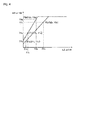
- Fig. 2 illustrates a relationship between the signal LA and the signal HA, and a relationship between the signal LB and the signal HB.
- the ideal relationship between the signal LA and the signal HA, and an ideal relationship between the signal LB and the signal HB are both represented by a dashed line L1 in Fig. 2 .
- offset and gain vary in the high-magnification amplifier and the low-magnification amplifier.
- the actual relationship between the signal LA and the signal HA and the actual relationship between the signal LB and the signal HB are represented by straight lines L2 and L3, respectively, which both deviate from the ideal dashed line L1.
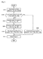
- the calculator 41 executes a correction parameter calculation process and a correction process, as shown below.
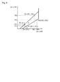
- the parameter calculator 41a arranges the optical head 10 in different positions with respect to the work piece Wand performs measurement at least twice. Thereby, measurement of points P1 A (X1 A , Y1 A ), P2 A (X2 A , Y2 A ), P1 B (X1 B , Y1 B ), and P2 B (X2 B , Y2 B ) is performed (S101).
- the voltage value of the signal LA detected by a first measurement is X1 A
- the voltage value of the corresponding signal HA is Y1 A
- the point expressed by X1 A and Y1 A is the point P1 A (X1 A , Y1 A ).
- the voltage value of the signal LA detected by a second measurement is X2 A
- the voltage value of the corresponding signal HA is Y2 A
- the point expressed by X2 A and Y2 A is the point P2 A (X2 A , Y2 A ).
- the points P1 B (X1 B , Y1 B ) and P2 B (X2 B , Y2 B ) are found for the signals LB and HB in a similar manner.
- the parameter calculator 41 a calculates correction parameters ⁇ B and ⁇ B based on the point P1 B (X1 B , Y1 B ) and the point P2 B (X2 B , Y2 B ) (S103). Calculation of ⁇ B and ⁇ B is similar to that of ⁇ A and ⁇ A , and thus a description thereof is omitted.
- the parameter calculator 41a stores the correction parameters ⁇ A , ⁇ A , ⁇ B , and ⁇ B in the memory 42 (S104).
- the corrector 41b simultaneously detects the signals LA, HA, LB, and HB (S201).
- the corrector 41b determines whether one of the signals HA and HB is equal to or greater than a threshold value THa (S202). Using the determination of step S202, a determination is also made as to whether one of the signal A and the signal B is equal to or greater than a predetermined threshold value.
- step S203 or S206 the S signal outputter 43 outputs the S signal (S207).
- Fig. 6 illustrates the S signal according to the comparative example.
- a horizontal axis in Fig. 6 represents a distance D between the objective lens 14 and the work piece W, while a vertical axis in Fig. 6 represents voltage of the S signal.
- the S signal is calculated based on the signals LA and LB in a range where D1 ⁇ D ⁇ D2. Meanwhile, the S signal is calculated based on the signals HA and HB in a range where D ⁇ D1 or D2 ⁇ D.
- the voltage value of the S signal matches a focus determination voltage
- a determination is made that the optical head 10 (objective lens 14) is in the focal position with respect to the work piece W.
- the signals LA and LB are corrected as described above and the signals CA and CB are calculated.
- the present embodiment calculates the S signal based on the post-correction signals CA and CB.
- an autofocus mechanism according to a second embodiment is described.
- the autofocus mechanism according to the second embodiment only the correction process differs from the first embodiment.
- Other configurations are similar to those of the first embodiment.
- the corrector 41b determines whether one of the signals LA and LB is equal to or less than the threshold value THb (S202a).
- step S202a When one of the signals LA and LB is determined to be equal to or less than the threshold value THb in step S202a (S202a: Yes), the corrector 41b executes step S203. Meanwhile, when one of the signals LA and LB is determined to not be equal to or less than the threshold value THb (S202a: No), the corrector 41b executes step S204.
- the second embodiment described above achieves a similar effect to that of the first embodiment.
- the first embodiment calculates the S signal based on the signals CA and CB, which are corrections of the signals LA and LB, respectively.
- the third embodiment calculates the S signal based on signals CA' and CB', which are corrections of the signals HA and HB, respectively.
- the third embodiment differs from the first embodiment in this respect.
- Other configurations of the third embodiment are similar to those of the first embodiment and so a description thereof is omitted.
- the voltage value of the signal HA detected by a first measurement is X1' A
- the voltage value of the corresponding signal LA is Y1' A
- the point expressed by X1' A and Y1' A is a point P1' A (X1' A , Y1' A ).
- the voltage value of the signal HA detected by a second measurement is X2' A
- the voltage value of the corresponding signal LA is Y2' A
- the point expressed by X2' A and Y2' A is a point P2' A (X2' A , Y2' A ).
- points P1' B (X1' B , Y1' B ) and P2' B (X2' B , Y2' B ) are found for the signals HB and LB in a similar manner.
- steps S201 and S202 are executed in a manner similar to that of the first embodiment.
- the third embodiment described above achieves a similar effect to that of the first embodiment.
- an autofocus mechanism according to a fourth embodiment is described.
- the autofocus mechanism according to the fourth embodiment only the correction process differs from the third embodiment.
- Other configurations are similar to those of the third embodiment.
- the corrector 41b determines whether one of the signals LA and LB is equal to or less than the threshold value THb (S202a).
- step S202a: No When neither of the signals LA and LB is determined to be equal to or less than the threshold value THb in step S202a (S202a: No), the corrector 41b executes step S203a. Meanwhile, when one of the signals LA and LB is determined to be equal to or less than the threshold value THb (S202a: Yes), the corrector 41b executes step S204a.
- the fourth embodiment described above achieves a similar effect to that of the first embodiment.
- the autofocus mechanism according to the present embodiment is a laser autofocus mechanism using a double knife-edge method.
- the autofocus mechanism according to the present embodiment includes an optical head 50, an amplifier 60, an AD converter 70, and the computer 40.
- a light source (laser diode) 51 emits laser light.
- the laser light traverses a tube lens 52 and a beam splitter 54 to pass through an objective lens 55, and is emitted on the work piece W.
- a beam of light that has passed through the objective lens 55 forms a light point image at the focal position of the objective lens 55.
- Fig. 12 illustrates an exemplary case where the focal position of the objective lens 55 is matched to the work piece W.
- the light reflected by the work piece W passes through the objective lens 55, is reflected by the beam splitter 54, passes through an auxiliary lens 53, and is guided to a triangular prism 56.
- a first portion forms a light point image on a halved sensor 57, which is configured by halved photoreceiver elements 57a and 57b.
- a second portion of the light forms a light point image on a halved sensor 58, which is configured by halved photoreceiver elements 58a and 58b.
- the light point image on the halved sensor 57 is blurry.
- the optical head 50 (objective lens 55) is closer to the work piece W than is the focal position, the amount of light received by the photoreceiver elements 57a and 58a increases.
- the optical head 50 (objective lens 55) is further away from the work piece W than is the focal position, the amount of light received by the photoreceiver elements 57b and 58b increases.
- the present embodiment can identify the focal position of the optical head 50 (objective lens 55) with respect to the work piece W. Moreover, the photoreceiver elements 57a and 57b output a signal C and a signal D, respectively, based on the amount of light received. The photoreceiver elements 58a and 58b output a signal E and a signal F, respectively, based on the amount of light received.
- the amplifier 60 includes a low-magnification amplifier 61 for the signal C, a high-magnification amplifier 62 for the signal C, a low-magnification amplifier 63 for the signal D, and a high-magnification amplifier 64 for the signal D.
- the amplifier 60 includes a low-magnification amplifier 65 for the signal E, a high-magnification amplifier 66 for the signal E, a low-magnification amplifier 67 for the signal F, and a high-magnification amplifier 68 for the signal F.
- the low-magnification amplifier 61 outputs a low-magnification amplified signal LC, which is an amplification of the signal C, to a channel CH1 of the AD converter 70.
- the high-magnification amplifier 62 outputs a high-magnification amplified signal HC to a channel CH2 of the AD converter 70, the high-magnification amplified signal HC being an amplification of the signal C by an amplification rate greater than the amplification rate of the low-magnification amplifier 61.
- the low-magnification amplifier 63 outputs a low-magnification amplified signal LD, which is an amplification of the signal D, to a channel CH3 of the AD converter 70.
- the high-magnification amplifier 64 outputs a high-magnification amplified signal HD to a channel CH4 of the AD converter 70, the high-magnification amplified signal HD being an amplification of the signal D by an amplification rate greater than the amplification rate of the low-magnification amplifier 63.
- the low-magnification amplifier 65 outputs a low-magnification amplified signal LE, which is an amplification of the signal E, to a channel CH5 of the AD converter 70.
- the high-magnification amplifier 66 outputs a high-magnification amplified signal HE to a channel CH6 of the AD converter 70, the high-magnification amplified signal HE being an amplification of the signal E by an amplification rate greater than the amplification rate of the low-magnification amplifier 65.
- the low-magnification amplifier 67 outputs a low-magnification amplified signal LF, which is an amplification of the signal F, to a channel CH7 of the AD converter 70.
- the high-magnification amplifier 68 outputs a high-magnification amplified signal HF to a channel CH8 of the AD converter 70, the high-magnification amplified signal HF being an amplification of the signal F by an amplification rate greater than the amplification rate of the low-magnification amplifier 67.
- the AD converter 30 converts the signals LC, HC, LD, HD, LE, HE, LF, and HF from analog signals into digital signals and outputs the converted signals to the computer 40.
- the computer 40 has a configuration substantially similar to that of the first embodiment. However, content processed by the calculator 41 according to the fifth embodiment is different from that of the first embodiment.
- the parameter calculator 41a arranges the optical head 50 in different positions with respect to the work piece W and performs measurement at least twice. Thereby, measurement of P1 C (X1 C , Y1 C ), P2 C (X2 C , Y2 C ), P1 D (X1 D , Y1 D ), P2 D (X2 D , Y2 D ), P1 E (X1 E , Y1 E ), P2 E (X2 E , Y2 E ), P1 F (X1 F , Y1 F ), and P2 F (X2 F , Y2 F ) is performed (S301).
- the voltage value of the signal LC detected by a first measurement is X1 C
- the voltage value of the corresponding signal HC is Y1 C
- the point expressed by X1 C and Y1 C is a point P1 C (X1 C , Y1 C ).
- the voltage value of the signal LC detected by a second measurement is X2 C
- the voltage value of the corresponding signal HC is Y2 C .
- the point expressed by X2 C and Y2 C is a point P2 C (X2 C , Y2 C ).
- points P1 D (X1 D , Y1 D ) and P2 D (X2 D , Y2 D ) are found in a similar manner for the signals LD and HD. Also, points P1 E (X1 E , Y1 E ) and P2 E (X2 E , Y2 E ) are found for the signals LE and HE, and points P1 F (X1 F , Y1 F ) and P2 F (X2 F , Y2 F ) are found for the signals LF and HF.
- the parameter calculator 41a calculates correction parameters ⁇ C and ⁇ C based on the point P1 C (X1 C , Y1 C ) and the point P2 C (X2 C , Y2 C ) (S302).
- the parameter calculator 41a calculates correction parameters ⁇ D and ⁇ D based on the point P1 D (X1 D , Y1 D ) and the point P2 D (X2 D , Y2 D ) (S303).
- the parameter calculator 41a calculates correction parameters ⁇ E and ⁇ E based on the point P1 E (X1 E , Y1 E ) and the point P2 E (X2 E , Y2 E ) (S304).
- the parameter calculator 41a calculates correction parameters ⁇ F and ⁇ F based on the point P1 F (X1 F , Y1 F ) and the point P2 F (X2 F , Y2 F ) (S305).
- the parameter calculator 41 a stores the correction parameters ⁇ C , ⁇ C , ⁇ D , ⁇ D , ⁇ E , ⁇ E , ⁇ F , and ⁇ F in the memory 42 (S306).
- the corrector 41b simultaneously detects the signals LC, HC, LD, HD, LE, HE, LF, and HF (S401). Next, the corrector 41b determines whether one of the signals HC, HD, HE, and HF is equal to or greater than the threshold value THa (S402).
- step S403 or S408 the S signal outputter 43 outputs the S signal (S409). This ends the correction process.
- the fifth embodiment with the configuration described above, achieves a similar effect to that of the first embodiment.
- the present invention is not limited to these and can include various modifications, additions, and the like not deviating from the scope of the present invention.
- the double knife-edge method was applied to the first embodiment.
- the double knife-edge method according to the fifth embodiment can also be applied to the second through fourth embodiments, as well.
Landscapes
- Physics & Mathematics (AREA)
- General Physics & Mathematics (AREA)
- Optics & Photonics (AREA)
- Chemical & Material Sciences (AREA)
- Analytical Chemistry (AREA)
- Automatic Focus Adjustment (AREA)
Abstract
Description
- The present application claims priority under 35 U.S.C. §119 of Japanese Application No.
2013-138159, filed on July 1, 2013 - The present invention relates to an autofocus mechanism adjusting a focal position with respect to a work piece.
- Conventionally, an autofocus mechanism used in a measurement device is known (see Japanese Patent Laid-open Publication No.
H07-105547 - However, offset and gain vary in the high-magnification amplifier and the low-magnification amplifier of the above-noted autofocus mechanism. Therefore, accuracy in identifying the focal position deteriorates. Moreover, feedback control, which tracks a surface of the work piece based on the focal position, cannot be performed stably.
- The present disclosure provides an autofocus mechanism with improved accuracy in identifying a focal position.
- An autofocus mechanism according to the present disclosure includes a light source emitting light through an objective lens at a work piece; a first detector detecting a first portion of light reflected by the work piece and generating a first signal; a second detector detecting a second portion of the reflected light and generating a second signal; a first amplifier amplifying a voltage value of the first signal by a first amplification rate and generating a first amplified signal; a second amplifier amplifying the voltage value of the first signal by a second amplification rate greater than the first amplification rate and generating a second amplified signal; a third amplifier amplifying the voltage value of the second signal by a third amplification rate and generating a third amplified signal; a fourth amplifier amplifying the voltage value of the second signal by a fourth amplification rate greater than the third amplification rate and generating a fourth amplified signal; a corrector correcting one of the first amplified signal and the second amplified signal based on a first correction function illustrating a relationship between the voltage value of the first amplified signal and the voltage value of the second amplified signal to generate one of a first corrected signal and a second corrected signal, and correcting one of the third amplified signal and the fourth amplified signal based on a second correction function illustrating a relationship between the voltage value of the third amplified signal and the voltage value of the fourth amplified signal to generate one of a third corrected signal and a fourth corrected signal; and a focal position identifier identifying a focal position of the objective lens with respect to the work piece based on the first amplified signal and the third amplified signal or the first corrected signal and the third corrected signal in a case where one of the first signal and the second signal is equal to or greater than a first threshold value. The focal position identifier identifies the focal position based on the second amplified signal and the fourth amplified signal or the second corrected signal and the fourth corrected signal in a case where one of the first signal and the second signal is not equal to or greater than the first threshold value.
- According to the present disclosure, the corrector corrects one of the first amplified signal and the second amplified signal based on the first correction function illustrating the relationship between the voltage value of the first amplified signal and the voltage value of the second amplified signal, and corrects one of the third amplified signal and the fourth amplified signal based on the second correction function illustrating the relationship between the voltage value of the third amplified signal and the voltage value of the fourth amplified signal. Accordingly, the present disclosure can provide an autofocus mechanism inhibiting the effect of variation in gain and offset of the first through fourth amplifiers, the autofocus mechanism having improved accuracy in identifying the focal position.
- The present invention is further described in the detailed description which follows, in reference to the noted plurality of drawings by way of non-limiting examples of exemplary embodiments of the present invention, in which like reference numerals represent similar parts throughout the several views of the drawings, and wherein:
-
Fig. 1 is a schematic view illustrating a configuration of an autofocus mechanism according to a first embodiment; -
Fig. 2 illustrates a relationship between a signal LA and a signal HA, and a relationship between a signal LB and a signal HB; -
Fig. 3 is a flowchart illustrating a correction parameter calculation process according to the first embodiment; -
Fig. 4 illustrates a method of finding correction parameters according to the first embodiment; -
Fig. 5 is a flowchart illustrating a correction process according to the first embodiment; -
Fig. 6 illustrates an S signal according to a comparative example; -
Fig. 7 illustrates an S signal according to the first embodiment; -
Fig. 8 is a flowchart illustrating a correction process according to a second embodiment; -
Fig. 9 illustrates a method of finding correction parameters according to a third embodiment; -
Fig. 10 is a flowchart illustrating a correction process according to the third embodiment; -
Fig. 11 is a flowchart illustrating a correction process according to a fourth embodiment; -
Fig. 12 is a schematic view illustrating a configuration of an autofocus mechanism according to a fifth embodiment; -
Fig. 13 is a flowchart illustrating a correction parameter calculation process according to the fifth embodiment; and -
Fig. 14 is a flowchart illustrating a correction process according to the fifth embodiment. - The particulars shown herein are by way of example and for purposes of illustrative discussion of the embodiments of the present invention only and are presented in the cause of providing what is believed to be the most useful and readily understood description of the principles and conceptual aspects of the present invention. In this regard, no attempt is made to show structural details of the present invention in more detail than is necessary for the fundamental understanding of the present invention, the description taken with the drawings making apparent to those skilled in the art how the forms of the present invention may be embodied in practice.
-
Fig. 1 is a schematic view illustrating a configuration of an autofocus mechanism according to a first embodiment. The autofocus mechanism according to the present embodiment is a laser autofocus mechanism using a so-called double pinhole method, and is installed in optical devices such as a microscope and an image measuring instrument, for example. - As shown in
Fig. 1 , the autofocus mechanism according to the present embodiment includes anoptical head 10, anamplifier 20, anAD converter 30, and acomputer 40. Theoptical head 10 emits laser light at a work piece W, receives the light reflected by the work piece W, and converts the reflected light into an electric signal. Theamplifier 20 amplifies the electric signal received from theoptical head 10. TheAD converter 30 converts the electric signal received from theamplifier 20 from an analog signal into a digital signal. Thecomputer 40 identifies a focal position with respect to the work piece W based on the signal received from theAD converter 30. - As shown in
Fig. 1 , in theoptical head 10, a light source (laser diode) 11 emits laser light, which is emitted at abeam splitter 12a. Thebeam splitter 12a allows light from thelight source 11 to pass and bombard atube lens 13, and reflects the light reflected by the work piece W onto abeam splitter 12b. - The
tube lens 13 converts the light from thebeam splitter 12a into parallel light, which is emitted through anobjective lens 14 at the work piece W. In addition, thetube lens 13 allows the light reflected by the work piece W to bombard thebeam splitter 12a. Thebeam splitter 12b scatters the light from thebeam splitter 12a and allows transmitted light to bombard, through apinhole 15a, a photo receiver element (photodiode) 16a. In addition, thebeam splitter 12b allows reflected light to bombard, through apinhole 15b, a photo receiver element (photodiode) 16b. Thephotoreceiver elements amplifier 20 based on an amount of light received. - In
Fig. 1 , when the optical head 10 (objective lens 14) is arranged in the focal position with respect to the work piece W, output of thephotoreceiver elements optical head 10 is arranged so as to be further away from the work piece W than is the focal position, the output of thephotoreceiver element 16b is greater than the output of thephotoreceiver element 16a. Meanwhile, when theoptical head 10 is arranged so as to be closer to the work piece W than is the focal position, the output of thephotoreceiver element 16b is less than the output of thephotoreceiver element 16a. Making use of such changes, the present embodiment can identify the focal position of the optical head 10 (objective lens 14) with respect to the work piece W. - As shown in
Fig. 1 , theamplifier 20 includes a low-magnification amplifier 21 for the signal A, a high-magnification amplifier 22 for the signal A, a low-magnification amplifier 23 for the signal B, and a high-magnification amplifier 24 for the signal B. The low-magnification amplifier 21 outputs a low-magnification amplified signal LA, which is an amplification of the signal A, to a channel CH1 of theAD converter 30. The high-magnification amplifier 22 outputs a high-magnification amplified signal HA to a channel CH2 of theAD converter 30, the high-magnification amplified signal HA being an amplification of the signal A by an amplification rate greater than the amplification rate of the low-magnification amplifier 21. The low-magnification amplifier 23 outputs a low-magnification amplified signal LB, which is an amplification of the signal B, to a channel CH3 of theAD converter 30. The high-magnification amplifier 24 outputs a high-magnification amplified signal HB to a channel CH4 of theAD converter 30, the high-magnification amplified signal HB being an amplification of the signal B by an amplification rate greater than the amplification rate of the low-magnification amplifier 23. - The
AD converter 30 converts the signals LA, HA, LB, and HB from analog signals into digital signals and outputs the converted signals to thecomputer 40. - As shown in
Fig. 1 , thecomputer 40 includes acalculator 41, amemory 42, and anS signal outputter 43. Thecalculator 41 executes various calculations based on the signals LA, HA, LB, and HB input from theAD converter 30. Thememory 42 stores correction parameters for correcting a voltage value of the signals. TheS signal outputter 42 outputs an S signal to an exterior. Herein, the S signal is a signal identifying the focal position of theobjective lens 14 with respect to the work piece W. For example, theS signal outputter 43 converts a digital signal to an analog signal and outputs the signal. Alternatively, theS signal outputter 43 outputs serial or parallel digital signals. - As shown in
Fig. 1 , thecalculator 41 includes aparameter calculator 41a, acorrector 41b, and anS signal calculator 41 c. Theparameter calculator 41 a calculates the correction parameters of the signals LA and LB. Thecorrector 41b corrects the signals LA and LB based on the correction parameters. TheS signal calculator 41c (focal position identifier) calculates the S signal, which identifies the focal position, based on the signals LA, LB, HA, and HB. - Here, a concrete description is given of correction in the autofocus mechanism.
Fig. 2 illustrates a relationship between the signal LA and the signal HA, and a relationship between the signal LB and the signal HB. The ideal relationship between the signal LA and the signal HA, and an ideal relationship between the signal LB and the signal HB are both represented by a dashed line L1 inFig. 2 . However, offset and gain vary in the high-magnification amplifier and the low-magnification amplifier. Accordingly, as shown inFig. 2 , the actual relationship between the signal LA and the signal HA and the actual relationship between the signal LB and the signal HB are represented by straight lines L2 and L3, respectively, which both deviate from the ideal dashed line L1. Accordingly, errors occur when the relationship between the signal LA and the signal HA is presumed to be the ideal relationship and the signals are corrected such that the signal LA matches the signal HA. Similarly, errors occur when the relationship between the signal LB and the signal HB is presumed to be the ideal relationship and the signals are corrected such that the signal LB matches the signal HB. - In the present embodiment, the calculator 41 (
parameter calculator 41 a andcorrector 41b) executes a correction parameter calculation process and a correction process, as shown below. As shown inFig. 3 , in the correction parameter calculation process, theparameter calculator 41a arranges theoptical head 10 in different positions with respect to the work piece Wand performs measurement at least twice. Thereby, measurement of points P1A (X1A, Y1A), P2A (X2A, Y2A), P1B (X1B, Y1B), and P2B (X2B, Y2B) is performed (S101). - In an example shown in
Fig. 4 , the voltage value of the signal LA detected by a first measurement is X1A, and the voltage value of the corresponding signal HA is Y1A. The point expressed by X1A and Y1A is the point P1A (X1A, Y1A). Further, the voltage value of the signal LA detected by a second measurement is X2A, and the voltage value of the corresponding signal HA is Y2A. The point expressed by X2A and Y2A is the point P2A (X2A, Y2A). In addition, the points P1B (X1B, Y1B) and P2B (X2B, Y2B) are found for the signals LB and HB in a similar manner. - Following step S101, the
parameter calculator 41a calculates correction parameters αA and βA based on the point P1A (X1A, Y1A) and the point P2A (X2A, Y2A) (S102). As shown inFig. 4 , a function linking the point P1A (X1A, Y1A) and the point P2A (X2A, Y2A) is expressed by [Y=αA+βA·X]. Specifically, αA is an intercept (offset) and βA is a slope (gain). Accordingly, the slope βA is found by [βA = (Y1A - Y2A) ÷ (X1A - X2A)] while the intercept αA is found by [αA=Y1A - βA·X1A]. - Following step S102, the
parameter calculator 41 a calculates correction parameters αB and βB based on the point P1B (X1B, Y1B) and the point P2B (X2B, Y2B) (S103). Calculation of αB and βB is similar to that of αA and βA, and thus a description thereof is omitted. In addition, theparameter calculator 41a stores the correction parameters αA, βA, αB, and βB in the memory 42 (S104). - Next, the correction process is described with reference to
Fig. 5 . As shown inFig. 5 , thecorrector 41b simultaneously detects the signals LA, HA, LB, and HB (S201). Next, thecorrector 41b determines whether one of the signals HA and HB is equal to or greater than a threshold value THa (S202). Using the determination of step S202, a determination is also made as to whether one of the signal A and the signal B is equal to or greater than a predetermined threshold value. - When one of the signals HA and HB is not equal to or greater than the threshold value THa (S202: No), the
S signal calculator 41c calculates the S signal based on [S signal = (HA - HB) ÷ (HA + HB)] (S203). - Meanwhile, when one of the signals HA and HB is equal to or greater than the threshold value THa (S202: Yes), the
corrector 41b corrects the signal LA based on [CA = αA + βA· LA] and calculates a signal CA (S204). Next, thecorrector 41b corrects the signal LB based on [CB = αB + βB· LB] and calculates a signal CB (S205). Then, theS signal calculator 41c calculates the S signal based on [S signal = (CA - CB) ÷ (CA + CB)] (S206). - Then, after step S203 or S206, the
S signal outputter 43 outputs the S signal (S207). - Next, an advantage of the present embodiment is described in comparison to a comparative example. The comparative example differs from the present embodiment in that the S signal is calculated without correcting the signals LA and LB.
Fig. 6 illustrates the S signal according to the comparative example. A horizontal axis inFig. 6 represents a distance D between theobjective lens 14 and the work piece W, while a vertical axis inFig. 6 represents voltage of the S signal. - In the comparative example, as shown in
Fig. 6 , the S signal is calculated based on the signals LA and LB in a range where D1 < D < D2. Meanwhile, the S signal is calculated based on the signals HA and HB in a range where D < D1 or D2 < D. In addition, when the voltage value of the S signal matches a focus determination voltage, a determination is made that the optical head 10 (objective lens 14) is in the focal position with respect to the work piece W. However, offset and gain vary in the high-magnification amplifier and the low-magnification amplifier. Accordingly, in the comparative example, a value of the S signal becomes discontinuous due to D = D1 or D = D2, where the signals used in calculation of the S signal are switched. Therefore, errors occur in the determination of the focal position. - In contrast, in the present embodiment, the signals LA and LB are corrected as described above and the signals CA and CB are calculated. In addition, the present embodiment calculates the S signal based on the post-correction signals CA and CB. Thus, the present embodiment inhibits an effect of variation in the gain and offset of the
amplifiers 21 to 24 and, as shown inFig. 7 , the value of the S signal is continuous even when D = D1 or D = D2. Accordingly, the present embodiment can determine the focal position more accurately than the comparative example. - Next, an autofocus mechanism according to a second embodiment is described. In the autofocus mechanism according to the second embodiment, only the correction process differs from the first embodiment. Other configurations are similar to those of the first embodiment.
- In the second embodiment, as shown in
Fig. 8 , after step S201, thecorrector 41b determines whether one of the signals LA and LB is equal to or less than the threshold value THb (S202a). - When one of the signals LA and LB is determined to be equal to or less than the threshold value THb in step S202a (S202a: Yes), the
corrector 41b executes step S203. Meanwhile, when one of the signals LA and LB is determined to not be equal to or less than the threshold value THb (S202a: No), thecorrector 41b executes step S204. The second embodiment described above achieves a similar effect to that of the first embodiment. - Next, an autofocus mechanism according to a third embodiment is described. The first embodiment calculates the S signal based on the signals CA and CB, which are corrections of the signals LA and LB, respectively. In contrast, the third embodiment calculates the S signal based on signals CA' and CB', which are corrections of the signals HA and HB, respectively. The third embodiment differs from the first embodiment in this respect. Other configurations of the third embodiment are similar to those of the first embodiment and so a description thereof is omitted.
- In the third embodiment, in an example shown in
Fig. 9 , the voltage value of the signal HA detected by a first measurement is X1'A, and the voltage value of the corresponding signal LA is Y1'A. The point expressed by X1'A and Y1'A is a point P1'A (X1'A, Y1'A). Further, the voltage value of the signal HA detected by a second measurement is X2'A, and the voltage value of the corresponding signal LA is Y2'A. The point expressed by X2'A and Y2'A is a point P2'A (X2'A, Y2'A). In addition, points P1'B (X1'B, Y1'B) and P2'B (X2'B, Y2'B) are found for the signals HB and LB in a similar manner. - Furthermore, as shown in
Fig. 9 , a function linking the point P1'A (X1'A, Y1'A) and the point P2'A (X2'A, Y2'A) is expressed by [Y = α'A + β'A· X]. Specifically, α'A is an intercept and β'A is a slope. Accordingly, the slope β'A is found by [β'A = (Y1'A - Y2'A) ÷ (X1'A - X2'A)] while the intercept α'A is found by [α'A = Y1'A - β'A· X1'A]. - Next, a correction process according to the third embodiment is described with reference to
Fig. 10 . First, steps S201 and S202 are executed in a manner similar to that of the first embodiment. - When the voltage value of one of the signals HA and HB is equal to or greater than the threshold value THa (S202: Yes), the
S signal calculator 41c calculates the S signal based on [S signal = (LA - LB) ÷ (LA + LB)] (S203a). - Meanwhile, when neither of the signals HA and HB is equal to or greater than the threshold value THa (S202: No), the
corrector 41b corrects the signal HA based on [CA' = α'A + β'A· HA] and calculates a signal CA' (S204a). Next, thecorrector 41b corrects the signal HB based on [CB' = α'B + β'B· HB] and calculates a signal CB' (S205a). Then, theS signal calculator 41c calculates the S signal based on [S signal = (CA' - CB') ÷ (CA' + CB')] (S206a). Subsequent processes are similar to those of the first embodiment and so a description thereof is omitted. The third embodiment described above achieves a similar effect to that of the first embodiment. - Next, an autofocus mechanism according to a fourth embodiment is described. In the autofocus mechanism according to the fourth embodiment, only the correction process differs from the third embodiment. Other configurations are similar to those of the third embodiment.
- In the fourth embodiment, as shown in
Fig. 11 , after step S201, thecorrector 41b determines whether one of the signals LA and LB is equal to or less than the threshold value THb (S202a). - When neither of the signals LA and LB is determined to be equal to or less than the threshold value THb in step S202a (S202a: No), the
corrector 41b executes step S203a. Meanwhile, when one of the signals LA and LB is determined to be equal to or less than the threshold value THb (S202a: Yes), thecorrector 41b executes step S204a. The fourth embodiment described above achieves a similar effect to that of the first embodiment. - Next, an autofocus mechanism according to a fifth embodiment is described with reference to
Fig. 12 . The autofocus mechanism according to the present embodiment is a laser autofocus mechanism using a double knife-edge method. As shown inFig. 12 , the autofocus mechanism according to the present embodiment includes anoptical head 50, anamplifier 60, anAD converter 70, and thecomputer 40. - As shown in
Fig. 12 , in theoptical head 50, a light source (laser diode) 51 emits laser light. The laser light traverses atube lens 52 and abeam splitter 54 to pass through anobjective lens 55, and is emitted on the work piece W. A beam of light that has passed through theobjective lens 55 forms a light point image at the focal position of theobjective lens 55.Fig. 12 illustrates an exemplary case where the focal position of theobjective lens 55 is matched to the work piece W. The light reflected by the work piece W passes through theobjective lens 55, is reflected by thebeam splitter 54, passes through anauxiliary lens 53, and is guided to atriangular prism 56. - Of the light split by the
triangular prism 56, a first portion forms a light point image on a halvedsensor 57, which is configured by halvedphotoreceiver elements sensor 58, which is configured by halvedphotoreceiver elements - In the present embodiment, when relative positions of the work piece W and the
optical head 50 change in an optical axis direction of theobjective lens 55 and the work piece W deviates from the focal position of theobjective lens 55, the light point image on the halvedsensor 57 is blurry. When the optical head 50 (objective lens 55) is closer to the work piece W than is the focal position, the amount of light received by thephotoreceiver elements photoreceiver elements photoreceiver elements photoreceiver elements - As shown in
Fig. 12 , theamplifier 60 includes a low-magnification amplifier 61 for the signal C, a high-magnification amplifier 62 for the signal C, a low-magnification amplifier 63 for the signal D, and a high-magnification amplifier 64 for the signal D. Moreover, theamplifier 60 includes a low-magnification amplifier 65 for the signal E, a high-magnification amplifier 66 for the signal E, a low-magnification amplifier 67 for the signal F, and a high-magnification amplifier 68 for the signal F. - The low-
magnification amplifier 61 outputs a low-magnification amplified signal LC, which is an amplification of the signal C, to a channel CH1 of theAD converter 70. The high-magnification amplifier 62 outputs a high-magnification amplified signal HC to a channel CH2 of theAD converter 70, the high-magnification amplified signal HC being an amplification of the signal C by an amplification rate greater than the amplification rate of the low-magnification amplifier 61. The low-magnification amplifier 63 outputs a low-magnification amplified signal LD, which is an amplification of the signal D, to a channel CH3 of theAD converter 70. The high-magnification amplifier 64 outputs a high-magnification amplified signal HD to a channel CH4 of theAD converter 70, the high-magnification amplified signal HD being an amplification of the signal D by an amplification rate greater than the amplification rate of the low-magnification amplifier 63. - The low-
magnification amplifier 65 outputs a low-magnification amplified signal LE, which is an amplification of the signal E, to a channel CH5 of theAD converter 70. The high-magnification amplifier 66 outputs a high-magnification amplified signal HE to a channel CH6 of theAD converter 70, the high-magnification amplified signal HE being an amplification of the signal E by an amplification rate greater than the amplification rate of the low-magnification amplifier 65. The low-magnification amplifier 67 outputs a low-magnification amplified signal LF, which is an amplification of the signal F, to a channel CH7 of theAD converter 70. The high-magnification amplifier 68 outputs a high-magnification amplified signal HF to a channel CH8 of theAD converter 70, the high-magnification amplified signal HF being an amplification of the signal F by an amplification rate greater than the amplification rate of the low-magnification amplifier 67. - The
AD converter 30 converts the signals LC, HC, LD, HD, LE, HE, LF, and HF from analog signals into digital signals and outputs the converted signals to thecomputer 40. - The
computer 40 has a configuration substantially similar to that of the first embodiment. However, content processed by thecalculator 41 according to the fifth embodiment is different from that of the first embodiment. - First, the correction parameter calculation process is described with reference to
Fig. 13 . In the fifth embodiment, theparameter calculator 41a arranges theoptical head 50 in different positions with respect to the work piece W and performs measurement at least twice. Thereby, measurement of P1C (X1C, Y1C), P2C (X2C, Y2C), P1D (X1D, Y1D), P2D (X2D, Y2D), P1E (X1E, Y1E), P2E (X2E, Y2E), P1F (X1F, Y1F), and P2F (X2F, Y2F) is performed (S301). - Here, the voltage value of the signal LC detected by a first measurement is X1C, and the voltage value of the corresponding signal HC is Y1C. The point expressed by X1C and Y1C is a point P1C (X1C, Y1C). Further, the voltage value of the signal LC detected by a second measurement is X2C, and the voltage value of the corresponding signal HC is Y2C. The point expressed by X2C and Y2C is a point P2C (X2C, Y2C). Moreover, points P1D (X1D, Y1D) and P2D (X2D, Y2D) are found in a similar manner for the signals LD and HD. Also, points P1E (X1E, Y1E) and P2E (X2E, Y2E) are found for the signals LE and HE, and points P1F (X1F, Y1F) and P2F (X2F, Y2F) are found for the signals LF and HF.
- Following step S301, the
parameter calculator 41a calculates correction parameters αC and βC based on the point P1C (X1C, Y1C) and the point P2C (X2C, Y2C) (S302). A function linking the point P1C (X1C, Y1C) and the point P2C (X2C, Y2C) is expressed by [Y = αC + βC· X]. The slope βC is found by [βC = (Y1C - Y2C) ÷ (X1C - X2C)] while the intercept αC is found by [αC = Y1C - βC · X1C]. - Then, the
parameter calculator 41a calculates correction parameters αD and βD based on the point P1D (X1D, Y1D) and the point P2D (X2D, Y2D) (S303). Next, theparameter calculator 41a calculates correction parameters αE and βE based on the point P1E (X1E, Y1E) and the point P2E (X2E, Y2E) (S304). Then, theparameter calculator 41a calculates correction parameters αF and βF based on the point P1F (X1F, Y1F) and the point P2F (X2F, Y2F) (S305). Calculation of the correction parameters αD, βD, αE, βE, αF, and βF is similar to that of the correction parameters αC and βC, and so a description thereof is omitted. In addition, theparameter calculator 41 a stores the correction parameters αC, βC, αD, βD, αE, βE, αF, and βF in the memory 42 (S306). - Next, the correction process is described with reference to
Fig. 14 . In the fifth embodiment, thecorrector 41b simultaneously detects the signals LC, HC, LD, HD, LE, HE, LF, and HF (S401). Next, thecorrector 41b determines whether one of the signals HC, HD, HE, and HF is equal to or greater than the threshold value THa (S402). - When one of the signals HC, HD, HE, and HF is not equal to or greater than the threshold value THa (S402: No), the
S signal calculator 41c calculates the S signal based on [S signal = (HC - HD) ÷ (HC + HD) + (HE - HF) ÷ (HE + HF)] (S403). - Meanwhile, when one of the signals HC, HD, HE, and HF is equal to or greater than the threshold value THa (S402: Yes), the
corrector 41b corrects the signal LC based on [CC = αC + βC · LC] and calculates a signal CC (S404). Next, thecorrector 41b corrects the signal LD based on [CD = αD + βD · LD] and calculates a signal CD (S405). - Then, the
corrector 41b corrects the signal LE based on [CE = αE + βE · LE] and calculates a signal CE (S406). Next, thecorrector 41b corrects the signal LF based on [CF = αF + βF · LF] and calculates a signal CF (S407). Then, theS signal calculator 41c calculates the S signal based on [S signal = (CC - CD) ÷ (CC + CD) + (CE - CF) ÷ (CE + CF)] (S408). - Then, after step S403 or S408, the
S signal outputter 43 outputs the S signal (S409). This ends the correction process. The fifth embodiment, with the configuration described above, achieves a similar effect to that of the first embodiment. - Embodiments of the present invention were described above, but the present invention is not limited to these and can include various modifications, additions, and the like not deviating from the scope of the present invention. For example, in the fifth embodiment, the double knife-edge method was applied to the first embodiment. However, the double knife-edge method according to the fifth embodiment can also be applied to the second through fourth embodiments, as well.
- It is noted that the foregoing examples have been provided merely for the purpose of explanation and are in no way to be construed as limiting of the present invention. While the present invention has been described with reference to exemplary embodiments, it is understood that the words which have been used herein are words of description and illustration, rather than words of limitation. Changes may be made, within the purview of the appended claims, as presently stated and as amended, without departing from the scope and spirit of the present invention in its aspects. Although the present invention has been described herein with reference to particular structures, materials and embodiments, the present invention is not intended to be limited to the particulars disclosed herein; rather, the present invention extends to all functionally equivalent structures, methods and uses, such as are within the scope of the appended claims.
- The present invention is not limited to the above described embodiments, and various variations and modifications may be possible without departing from the scope of the present invention.
- Features, components and specific details of the structures of the above-described embodiments may be exchanged or combined to form further embodiments optimized for the respective application. As far as those modifications are readily apparent for an expert skilled in the art they shall be disclosed implicitly by the above description without specifying explicitly every possible combination, for the sake of conciseness of the present description.
Claims (3)
- An autofocus mechanism comprising:a light source (11) configured to emit light through an objective lens (14) at a work piece (W);a first detector (16b) configured to detect a first portion of light reflected by the work piece (W) and generate a first signal (A);a second detector (16a) configured to detect a second portion of the reflected light and generate a second signal (B);a first amplifier (21) configured to amplify a voltage value of the first signal (A) by a first amplification rate and generate a first amplified signal (LA);a second amplifier (22) configured to amplify the voltage value of the first signal (A) by a second amplification rate greater than the first amplification rate, and to generate a second amplified signal (HA);a third amplifier (23) configured to amplify the voltage value of the second signal (B) by a third amplification rate, and to generate a third amplified signal (LB);a fourth amplifier (24) configured to amplify the voltage value of the second signal (B) by a fourth amplification rate greater than the third amplification rate, and to generate a fourth amplified signal (HB);a corrector (41b) configured to correct one of the first amplified signal (LA) and the second amplified signal (HA) based on a first correction function expressing a relationship between the voltage value of the first amplified signal (LA) and the voltage value of the second amplified signal (HA) to generate one of a first corrected signal (CA) and a second corrected signal (CA'), the corrector (41b) further configured to correct one of the third amplified signal (LB) and the fourth amplified signal (HB) based on a second correction function expressing a relationship between the voltage value of the third amplified signal (LB) and the voltage value of the fourth amplified signal (HB) to generate one of a third corrected signal (CB) and a fourth corrected signal (CB'); anda focal position identifier (41c) configured to identify a focal position of the objective lens (14) with respect to the work piece (W) based on the first amplified signal (LA) and the third amplified signal (LB) or the first corrected signal (CA) and the third corrected signal (CB) in a case where one of the first signal (A) and the second signal (B) is equal to or greater than a first threshold value, wherein the focal position identifier (41 c) identifies the focal position based on the second amplified signal (HA) and the fourth amplified signal (HB) or the second corrected signal (CA') and the fourth corrected signal (CB') in a case where one of the first signal (A) and the second signal (B) is not equal to or greater than the first threshold value.
- The autofocus mechanism according to claim 1, wherein the focal position identifier (41c) identifies the focal position based on the first corrected signal (CA) and the third corrected signal (CB) in a case where one of the first signal (A) and the second signal (B) is equal to or greater than the first threshold value, and
the focal position identifier (41 c) further identifies the focal position based on the second amplified signal (HA) and the fourth amplified signal (HB) in a case where one of the first signal (A) and the second signal (B) is not equal to or greater than the first threshold value. - The autofocus mechanism according to claim 1, wherein the focal position identifier (41c) identifies the focal position based on the first amplified signal (LA) and the third amplified signal (LB) in a case where one of the first signal (A) and the second signal (B) is equal to or greater than the first threshold value, and
the focal position identifier (41 c) identifies the focal position based on the second corrected signal (CA') and the fourth corrected signal (CB') in a case where one of the first signal (A) and the second signal (B) is not equal to or greater than the first threshold value.
Applications Claiming Priority (1)
| Application Number | Priority Date | Filing Date | Title |
|---|---|---|---|
| JP2013138159A JP6099504B2 (en) | 2013-07-01 | 2013-07-01 | Autofocus device |
Publications (2)
| Publication Number | Publication Date |
|---|---|
| EP2821838A1 true EP2821838A1 (en) | 2015-01-07 |
| EP2821838B1 EP2821838B1 (en) | 2016-04-27 |
Family
ID=51059311
Family Applications (1)
| Application Number | Title | Priority Date | Filing Date |
|---|---|---|---|
| EP14174938.2A Active EP2821838B1 (en) | 2013-07-01 | 2014-06-30 | Autofocus mechanism |
Country Status (3)
| Country | Link |
|---|---|
| US (1) | US9341812B2 (en) |
| EP (1) | EP2821838B1 (en) |
| JP (1) | JP6099504B2 (en) |
Families Citing this family (1)
| Publication number | Priority date | Publication date | Assignee | Title |
|---|---|---|---|---|
| JP2016071010A (en) | 2014-09-29 | 2016-05-09 | 株式会社ミツトヨ | Autofocus device, autofocus method, and program |
Citations (4)
| Publication number | Priority date | Publication date | Assignee | Title |
|---|---|---|---|---|
| US4926407A (en) * | 1986-12-25 | 1990-05-15 | Kabushiki Kaisha Toshiba | Optical data processor |
| JPH07105547A (en) | 1993-10-01 | 1995-04-21 | Mitsutoyo Corp | Automatic focusing mechanism |
| JP2001242375A (en) * | 2000-02-29 | 2001-09-07 | Nikon Corp | Focus adjustment device and microscope |
| JP2009087512A (en) * | 2007-10-03 | 2009-04-23 | Sony Corp | Information processing apparatus and method, and program |
Family Cites Families (2)
| Publication number | Priority date | Publication date | Assignee | Title |
|---|---|---|---|---|
| US5568309A (en) * | 1994-04-24 | 1996-10-22 | Hughes Aircraft Company | System and method for amplification and wavefront compensation of depolarized optical beams |
| JP3976316B2 (en) * | 2002-10-18 | 2007-09-19 | 富士フイルム株式会社 | Image playback device |
-
2013
- 2013-07-01 JP JP2013138159A patent/JP6099504B2/en active Active
-
2014
- 2014-06-26 US US14/315,876 patent/US9341812B2/en active Active
- 2014-06-30 EP EP14174938.2A patent/EP2821838B1/en active Active
Patent Citations (4)
| Publication number | Priority date | Publication date | Assignee | Title |
|---|---|---|---|---|
| US4926407A (en) * | 1986-12-25 | 1990-05-15 | Kabushiki Kaisha Toshiba | Optical data processor |
| JPH07105547A (en) | 1993-10-01 | 1995-04-21 | Mitsutoyo Corp | Automatic focusing mechanism |
| JP2001242375A (en) * | 2000-02-29 | 2001-09-07 | Nikon Corp | Focus adjustment device and microscope |
| JP2009087512A (en) * | 2007-10-03 | 2009-04-23 | Sony Corp | Information processing apparatus and method, and program |
Also Published As
| Publication number | Publication date |
|---|---|
| JP2015011273A (en) | 2015-01-19 |
| JP6099504B2 (en) | 2017-03-22 |
| US20150001374A1 (en) | 2015-01-01 |
| EP2821838B1 (en) | 2016-04-27 |
| US9341812B2 (en) | 2016-05-17 |
Similar Documents
| Publication | Publication Date | Title |
|---|---|---|
| JP5723517B2 (en) | Optical distance measuring device | |
| US20170090433A1 (en) | Servo control system having function of measuring characteristic of learning controller | |
| KR101429838B1 (en) | Displacement sensor | |
| EP2821838B1 (en) | Autofocus mechanism | |
| WO2020046488A3 (en) | A multiple working distance height sensor using multiple wavelengths | |
| US9638911B2 (en) | Autofocus mechanism | |
| US10444360B2 (en) | Displacement measurement device, measurement system, and displacement measurement method | |
| JP4979916B2 (en) | Surveying device and surveying method | |
| CN112415888B (en) | Double-position-ring switching control method and control system for fine sighting telescope | |
| WO2017042995A1 (en) | In-vehicle stereo camera device and method for correcting same | |
| JP4679411B2 (en) | Optical communication device | |
| US8045860B2 (en) | Optical transceiver | |
| JP2014215232A (en) | Yaw rate detection apparatus | |
| US9256061B2 (en) | Focus control apparatus and method | |
| TWI667464B (en) | Optical measurement device and optical measurement method | |
| US8559019B2 (en) | Apparatus and method for measuring displacement, method of making die for molding optical element, and optical element | |
| EP3543645B1 (en) | Optical measurement device and optical measurement method | |
| KR101850024B1 (en) | Apparatus and method for measuring path difference in optical interferometer using ofdr | |
| US10760962B2 (en) | Light detector, correction coefficient calculation device, and correction coefficient calculation method | |
| CN113253360B (en) | Analog photoelectric sensor correction method and device | |
| CN121541579B (en) | A Low-Drift Laser Scanning Control Method and System Based on Dynamic Error Compensation | |
| JP3874116B2 (en) | Optical disc reproducing apparatus and offset adjusting method | |
| US11426060B2 (en) | Optical scanning endoscope device | |
| Masuda et al. | Optically Amplified Feedback-Circuit Scheme for Optical Measurement Applications with Significantly Improved Optical-Power Resolutions | |
| CN113098610A (en) | Signal receiving apparatus, control method of signal receiving apparatus, and optical communication system |
Legal Events
| Date | Code | Title | Description |
|---|---|---|---|
| PUAI | Public reference made under article 153(3) epc to a published international application that has entered the european phase |
Free format text: ORIGINAL CODE: 0009012 |
|
| 17P | Request for examination filed |
Effective date: 20140630 |
|
| AK | Designated contracting states |
Kind code of ref document: A1 Designated state(s): AL AT BE BG CH CY CZ DE DK EE ES FI FR GB GR HR HU IE IS IT LI LT LU LV MC MK MT NL NO PL PT RO RS SE SI SK SM TR |
|
| AX | Request for extension of the european patent |
Extension state: BA ME |
|
| R17P | Request for examination filed (corrected) |
Effective date: 20150610 |
|
| RBV | Designated contracting states (corrected) |
Designated state(s): AL AT BE BG CH CY CZ DE DK EE ES FI FR GB GR HR HU IE IS IT LI LT LU LV MC MK MT NL NO PL PT RO RS SE SI SK SM TR |
|
| RIC1 | Information provided on ipc code assigned before grant |
Ipc: G02B 21/24 20060101AFI20150924BHEP Ipc: G02B 7/28 20060101ALI20150924BHEP Ipc: G02B 7/38 20060101ALN20150924BHEP |
|
| GRAP | Despatch of communication of intention to grant a patent |
Free format text: ORIGINAL CODE: EPIDOSNIGR1 |
|
| INTG | Intention to grant announced |
Effective date: 20151030 |
|
| GRAS | Grant fee paid |
Free format text: ORIGINAL CODE: EPIDOSNIGR3 |
|
| GRAA | (expected) grant |
Free format text: ORIGINAL CODE: 0009210 |
|
| AK | Designated contracting states |
Kind code of ref document: B1 Designated state(s): AL AT BE BG CH CY CZ DE DK EE ES FI FR GB GR HR HU IE IS IT LI LT LU LV MC MK MT NL NO PL PT RO RS SE SI SK SM TR |
|
| REG | Reference to a national code |
Ref country code: GB Ref legal event code: FG4D |
|
| REG | Reference to a national code |
Ref country code: CH Ref legal event code: EP |
|
| REG | Reference to a national code |
Ref country code: AT Ref legal event code: REF Ref document number: 795407 Country of ref document: AT Kind code of ref document: T Effective date: 20160515 |
|
| REG | Reference to a national code |
Ref country code: IE Ref legal event code: FG4D |
|
| REG | Reference to a national code |
Ref country code: DE Ref legal event code: R096 Ref document number: 602014001673 Country of ref document: DE |
|
| REG | Reference to a national code |
Ref country code: LT Ref legal event code: MG4D |
|
| REG | Reference to a national code |
Ref country code: NL Ref legal event code: MP Effective date: 20160427 |
|
| REG | Reference to a national code |
Ref country code: AT Ref legal event code: MK05 Ref document number: 795407 Country of ref document: AT Kind code of ref document: T Effective date: 20160427 |
|
| PG25 | Lapsed in a contracting state [announced via postgrant information from national office to epo] |
Ref country code: NL Free format text: LAPSE BECAUSE OF FAILURE TO SUBMIT A TRANSLATION OF THE DESCRIPTION OR TO PAY THE FEE WITHIN THE PRESCRIBED TIME-LIMIT Effective date: 20160427 |
|
| PG25 | Lapsed in a contracting state [announced via postgrant information from national office to epo] |
Ref country code: LT Free format text: LAPSE BECAUSE OF FAILURE TO SUBMIT A TRANSLATION OF THE DESCRIPTION OR TO PAY THE FEE WITHIN THE PRESCRIBED TIME-LIMIT Effective date: 20160427 Ref country code: PL Free format text: LAPSE BECAUSE OF FAILURE TO SUBMIT A TRANSLATION OF THE DESCRIPTION OR TO PAY THE FEE WITHIN THE PRESCRIBED TIME-LIMIT Effective date: 20160427 Ref country code: NO Free format text: LAPSE BECAUSE OF FAILURE TO SUBMIT A TRANSLATION OF THE DESCRIPTION OR TO PAY THE FEE WITHIN THE PRESCRIBED TIME-LIMIT Effective date: 20160727 Ref country code: FI Free format text: LAPSE BECAUSE OF FAILURE TO SUBMIT A TRANSLATION OF THE DESCRIPTION OR TO PAY THE FEE WITHIN THE PRESCRIBED TIME-LIMIT Effective date: 20160427 |
|
| PG25 | Lapsed in a contracting state [announced via postgrant information from national office to epo] |
Ref country code: SE Free format text: LAPSE BECAUSE OF FAILURE TO SUBMIT A TRANSLATION OF THE DESCRIPTION OR TO PAY THE FEE WITHIN THE PRESCRIBED TIME-LIMIT Effective date: 20160427 Ref country code: AT Free format text: LAPSE BECAUSE OF FAILURE TO SUBMIT A TRANSLATION OF THE DESCRIPTION OR TO PAY THE FEE WITHIN THE PRESCRIBED TIME-LIMIT Effective date: 20160427 Ref country code: GR Free format text: LAPSE BECAUSE OF FAILURE TO SUBMIT A TRANSLATION OF THE DESCRIPTION OR TO PAY THE FEE WITHIN THE PRESCRIBED TIME-LIMIT Effective date: 20160728 Ref country code: ES Free format text: LAPSE BECAUSE OF FAILURE TO SUBMIT A TRANSLATION OF THE DESCRIPTION OR TO PAY THE FEE WITHIN THE PRESCRIBED TIME-LIMIT Effective date: 20160427 Ref country code: HR Free format text: LAPSE BECAUSE OF FAILURE TO SUBMIT A TRANSLATION OF THE DESCRIPTION OR TO PAY THE FEE WITHIN THE PRESCRIBED TIME-LIMIT Effective date: 20160427 Ref country code: LV Free format text: LAPSE BECAUSE OF FAILURE TO SUBMIT A TRANSLATION OF THE DESCRIPTION OR TO PAY THE FEE WITHIN THE PRESCRIBED TIME-LIMIT Effective date: 20160427 Ref country code: PT Free format text: LAPSE BECAUSE OF FAILURE TO SUBMIT A TRANSLATION OF THE DESCRIPTION OR TO PAY THE FEE WITHIN THE PRESCRIBED TIME-LIMIT Effective date: 20160829 Ref country code: RS Free format text: LAPSE BECAUSE OF FAILURE TO SUBMIT A TRANSLATION OF THE DESCRIPTION OR TO PAY THE FEE WITHIN THE PRESCRIBED TIME-LIMIT Effective date: 20160427 |
|
| PG25 | Lapsed in a contracting state [announced via postgrant information from national office to epo] |
Ref country code: BE Free format text: LAPSE BECAUSE OF FAILURE TO SUBMIT A TRANSLATION OF THE DESCRIPTION OR TO PAY THE FEE WITHIN THE PRESCRIBED TIME-LIMIT Effective date: 20160427 Ref country code: IT Free format text: LAPSE BECAUSE OF FAILURE TO SUBMIT A TRANSLATION OF THE DESCRIPTION OR TO PAY THE FEE WITHIN THE PRESCRIBED TIME-LIMIT Effective date: 20160427 |
|
| REG | Reference to a national code |
Ref country code: DE Ref legal event code: R097 Ref document number: 602014001673 Country of ref document: DE |
|
| PG25 | Lapsed in a contracting state [announced via postgrant information from national office to epo] |
Ref country code: SK Free format text: LAPSE BECAUSE OF FAILURE TO SUBMIT A TRANSLATION OF THE DESCRIPTION OR TO PAY THE FEE WITHIN THE PRESCRIBED TIME-LIMIT Effective date: 20160427 Ref country code: MC Free format text: LAPSE BECAUSE OF FAILURE TO SUBMIT A TRANSLATION OF THE DESCRIPTION OR TO PAY THE FEE WITHIN THE PRESCRIBED TIME-LIMIT Effective date: 20160427 Ref country code: EE Free format text: LAPSE BECAUSE OF FAILURE TO SUBMIT A TRANSLATION OF THE DESCRIPTION OR TO PAY THE FEE WITHIN THE PRESCRIBED TIME-LIMIT Effective date: 20160427 Ref country code: CZ Free format text: LAPSE BECAUSE OF FAILURE TO SUBMIT A TRANSLATION OF THE DESCRIPTION OR TO PAY THE FEE WITHIN THE PRESCRIBED TIME-LIMIT Effective date: 20160427 Ref country code: DK Free format text: LAPSE BECAUSE OF FAILURE TO SUBMIT A TRANSLATION OF THE DESCRIPTION OR TO PAY THE FEE WITHIN THE PRESCRIBED TIME-LIMIT Effective date: 20160427 Ref country code: RO Free format text: LAPSE BECAUSE OF FAILURE TO SUBMIT A TRANSLATION OF THE DESCRIPTION OR TO PAY THE FEE WITHIN THE PRESCRIBED TIME-LIMIT Effective date: 20160427 |
|
| PG25 | Lapsed in a contracting state [announced via postgrant information from national office to epo] |
Ref country code: SM Free format text: LAPSE BECAUSE OF FAILURE TO SUBMIT A TRANSLATION OF THE DESCRIPTION OR TO PAY THE FEE WITHIN THE PRESCRIBED TIME-LIMIT Effective date: 20160427 |
|
| PLBE | No opposition filed within time limit |
Free format text: ORIGINAL CODE: 0009261 |
|
| STAA | Information on the status of an ep patent application or granted ep patent |
Free format text: STATUS: NO OPPOSITION FILED WITHIN TIME LIMIT |
|
| REG | Reference to a national code |
Ref country code: IE Ref legal event code: MM4A |
|
| REG | Reference to a national code |
Ref country code: FR Ref legal event code: ST Effective date: 20170228 |
|
| 26N | No opposition filed |
Effective date: 20170130 |
|
| PG25 | Lapsed in a contracting state [announced via postgrant information from national office to epo] |
Ref country code: FR Free format text: LAPSE BECAUSE OF NON-PAYMENT OF DUE FEES Effective date: 20160630 |
|
| PG25 | Lapsed in a contracting state [announced via postgrant information from national office to epo] |
Ref country code: SI Free format text: LAPSE BECAUSE OF FAILURE TO SUBMIT A TRANSLATION OF THE DESCRIPTION OR TO PAY THE FEE WITHIN THE PRESCRIBED TIME-LIMIT Effective date: 20160427 Ref country code: IE Free format text: LAPSE BECAUSE OF NON-PAYMENT OF DUE FEES Effective date: 20160630 |
|
| REG | Reference to a national code |
Ref country code: CH Ref legal event code: PL |
|
| PG25 | Lapsed in a contracting state [announced via postgrant information from national office to epo] |
Ref country code: CH Free format text: LAPSE BECAUSE OF NON-PAYMENT OF DUE FEES Effective date: 20170630 Ref country code: LI Free format text: LAPSE BECAUSE OF NON-PAYMENT OF DUE FEES Effective date: 20170630 |
|
| PG25 | Lapsed in a contracting state [announced via postgrant information from national office to epo] |
Ref country code: HU Free format text: LAPSE BECAUSE OF FAILURE TO SUBMIT A TRANSLATION OF THE DESCRIPTION OR TO PAY THE FEE WITHIN THE PRESCRIBED TIME-LIMIT; INVALID AB INITIO Effective date: 20140630 |
|
| PG25 | Lapsed in a contracting state [announced via postgrant information from national office to epo] |
Ref country code: MT Free format text: LAPSE BECAUSE OF NON-PAYMENT OF DUE FEES Effective date: 20160630 Ref country code: CY Free format text: LAPSE BECAUSE OF FAILURE TO SUBMIT A TRANSLATION OF THE DESCRIPTION OR TO PAY THE FEE WITHIN THE PRESCRIBED TIME-LIMIT Effective date: 20160427 Ref country code: LU Free format text: LAPSE BECAUSE OF NON-PAYMENT OF DUE FEES Effective date: 20160630 Ref country code: MK Free format text: LAPSE BECAUSE OF FAILURE TO SUBMIT A TRANSLATION OF THE DESCRIPTION OR TO PAY THE FEE WITHIN THE PRESCRIBED TIME-LIMIT Effective date: 20160427 Ref country code: IS Free format text: LAPSE BECAUSE OF FAILURE TO SUBMIT A TRANSLATION OF THE DESCRIPTION OR TO PAY THE FEE WITHIN THE PRESCRIBED TIME-LIMIT Effective date: 20160427 |
|
| PG25 | Lapsed in a contracting state [announced via postgrant information from national office to epo] |
Ref country code: BG Free format text: LAPSE BECAUSE OF FAILURE TO SUBMIT A TRANSLATION OF THE DESCRIPTION OR TO PAY THE FEE WITHIN THE PRESCRIBED TIME-LIMIT Effective date: 20160427 |
|
| PG25 | Lapsed in a contracting state [announced via postgrant information from national office to epo] |
Ref country code: TR Free format text: LAPSE BECAUSE OF FAILURE TO SUBMIT A TRANSLATION OF THE DESCRIPTION OR TO PAY THE FEE WITHIN THE PRESCRIBED TIME-LIMIT Effective date: 20160427 Ref country code: AL Free format text: LAPSE BECAUSE OF FAILURE TO SUBMIT A TRANSLATION OF THE DESCRIPTION OR TO PAY THE FEE WITHIN THE PRESCRIBED TIME-LIMIT Effective date: 20160427 |
|
| PGFP | Annual fee paid to national office [announced via postgrant information from national office to epo] |
Ref country code: DE Payment date: 20250618 Year of fee payment: 12 |
|
| PGFP | Annual fee paid to national office [announced via postgrant information from national office to epo] |
Ref country code: GB Payment date: 20250618 Year of fee payment: 12 |