EP2821669B2 - Vibration reduction device - Google Patents
Vibration reduction device Download PDFInfo
- Publication number
- EP2821669B2 EP2821669B2 EP12870149.7A EP12870149A EP2821669B2 EP 2821669 B2 EP2821669 B2 EP 2821669B2 EP 12870149 A EP12870149 A EP 12870149A EP 2821669 B2 EP2821669 B2 EP 2821669B2
- Authority
- EP
- European Patent Office
- Prior art keywords
- rotary member
- input side
- side plate
- output side
- output
- Prior art date
- Legal status (The legal status is an assumption and is not a legal conclusion. Google has not performed a legal analysis and makes no representation as to the accuracy of the status listed.)
- Not-in-force
Links
- 238000005096 rolling process Methods 0.000 claims description 50
- 238000013016 damping Methods 0.000 claims description 17
- 230000005540 biological transmission Effects 0.000 claims description 16
- 230000037431 insertion Effects 0.000 claims description 14
- 238000003780 insertion Methods 0.000 claims description 14
- 238000007789 sealing Methods 0.000 claims description 10
- 239000012530 fluid Substances 0.000 claims description 9
- 230000000149 penetrating effect Effects 0.000 claims description 2
- 230000010349 pulsation Effects 0.000 description 13
- 230000010355 oscillation Effects 0.000 description 6
- 239000006096 absorbing agent Substances 0.000 description 3
- 230000009471 action Effects 0.000 description 2
- 238000005452 bending Methods 0.000 description 2
- 230000001771 impaired effect Effects 0.000 description 2
- 230000004075 alteration Effects 0.000 description 1
- 230000008859 change Effects 0.000 description 1
- 230000008878 coupling Effects 0.000 description 1
- 238000010168 coupling process Methods 0.000 description 1
- 238000005859 coupling reaction Methods 0.000 description 1
- 230000000881 depressing effect Effects 0.000 description 1
- 230000000994 depressogenic effect Effects 0.000 description 1
- 230000005484 gravity Effects 0.000 description 1
- 239000004519 grease Substances 0.000 description 1
- 230000007246 mechanism Effects 0.000 description 1
- 230000000644 propagated effect Effects 0.000 description 1
- 239000011347 resin Substances 0.000 description 1
- 229920005989 resin Polymers 0.000 description 1
Images

Classifications
-
- F—MECHANICAL ENGINEERING; LIGHTING; HEATING; WEAPONS; BLASTING
- F16—ENGINEERING ELEMENTS AND UNITS; GENERAL MEASURES FOR PRODUCING AND MAINTAINING EFFECTIVE FUNCTIONING OF MACHINES OR INSTALLATIONS; THERMAL INSULATION IN GENERAL
- F16H—GEARING
- F16H45/00—Combinations of fluid gearings for conveying rotary motion with couplings or clutches
- F16H45/02—Combinations of fluid gearings for conveying rotary motion with couplings or clutches with mechanical clutches for bridging a fluid gearing of the hydrokinetic type
-
- F—MECHANICAL ENGINEERING; LIGHTING; HEATING; WEAPONS; BLASTING
- F16—ENGINEERING ELEMENTS AND UNITS; GENERAL MEASURES FOR PRODUCING AND MAINTAINING EFFECTIVE FUNCTIONING OF MACHINES OR INSTALLATIONS; THERMAL INSULATION IN GENERAL
- F16D—COUPLINGS FOR TRANSMITTING ROTATION; CLUTCHES; BRAKES
- F16D33/00—Rotary fluid couplings or clutches of the hydrokinetic type
- F16D33/18—Details
-
- F—MECHANICAL ENGINEERING; LIGHTING; HEATING; WEAPONS; BLASTING
- F16—ENGINEERING ELEMENTS AND UNITS; GENERAL MEASURES FOR PRODUCING AND MAINTAINING EFFECTIVE FUNCTIONING OF MACHINES OR INSTALLATIONS; THERMAL INSULATION IN GENERAL
- F16F—SPRINGS; SHOCK-ABSORBERS; MEANS FOR DAMPING VIBRATION
- F16F15/00—Suppression of vibrations in systems; Means or arrangements for avoiding or reducing out-of-balance forces, e.g. due to motion
- F16F15/10—Suppression of vibrations in rotating systems by making use of members moving with the system
- F16F15/14—Suppression of vibrations in rotating systems by making use of members moving with the system using masses freely rotating with the system, i.e. uninvolved in transmitting driveline torque, e.g. rotative dynamic dampers
- F16F15/1407—Suppression of vibrations in rotating systems by making use of members moving with the system using masses freely rotating with the system, i.e. uninvolved in transmitting driveline torque, e.g. rotative dynamic dampers the rotation being limited with respect to the driving means
- F16F15/145—Masses mounted with play with respect to driving means thus enabling free movement over a limited range
-
- F—MECHANICAL ENGINEERING; LIGHTING; HEATING; WEAPONS; BLASTING
- F16—ENGINEERING ELEMENTS AND UNITS; GENERAL MEASURES FOR PRODUCING AND MAINTAINING EFFECTIVE FUNCTIONING OF MACHINES OR INSTALLATIONS; THERMAL INSULATION IN GENERAL
- F16F—SPRINGS; SHOCK-ABSORBERS; MEANS FOR DAMPING VIBRATION
- F16F7/00—Vibration-dampers; Shock-absorbers
- F16F7/10—Vibration-dampers; Shock-absorbers using inertia effect
- F16F7/1028—Vibration-dampers; Shock-absorbers using inertia effect the inertia-producing means being a constituent part of the system which is to be damped
-
- F—MECHANICAL ENGINEERING; LIGHTING; HEATING; WEAPONS; BLASTING
- F16—ENGINEERING ELEMENTS AND UNITS; GENERAL MEASURES FOR PRODUCING AND MAINTAINING EFFECTIVE FUNCTIONING OF MACHINES OR INSTALLATIONS; THERMAL INSULATION IN GENERAL
- F16H—GEARING
- F16H45/00—Combinations of fluid gearings for conveying rotary motion with couplings or clutches
- F16H45/02—Combinations of fluid gearings for conveying rotary motion with couplings or clutches with mechanical clutches for bridging a fluid gearing of the hydrokinetic type
- F16H2045/0205—Combinations of fluid gearings for conveying rotary motion with couplings or clutches with mechanical clutches for bridging a fluid gearing of the hydrokinetic type two chamber system, i.e. without a separated, closed chamber specially adapted for actuating a lock-up clutch
-
- F—MECHANICAL ENGINEERING; LIGHTING; HEATING; WEAPONS; BLASTING
- F16—ENGINEERING ELEMENTS AND UNITS; GENERAL MEASURES FOR PRODUCING AND MAINTAINING EFFECTIVE FUNCTIONING OF MACHINES OR INSTALLATIONS; THERMAL INSULATION IN GENERAL
- F16H—GEARING
- F16H45/00—Combinations of fluid gearings for conveying rotary motion with couplings or clutches
- F16H45/02—Combinations of fluid gearings for conveying rotary motion with couplings or clutches with mechanical clutches for bridging a fluid gearing of the hydrokinetic type
- F16H2045/0221—Combinations of fluid gearings for conveying rotary motion with couplings or clutches with mechanical clutches for bridging a fluid gearing of the hydrokinetic type with damping means
- F16H2045/0226—Combinations of fluid gearings for conveying rotary motion with couplings or clutches with mechanical clutches for bridging a fluid gearing of the hydrokinetic type with damping means comprising two or more vibration dampers
- F16H2045/0231—Combinations of fluid gearings for conveying rotary motion with couplings or clutches with mechanical clutches for bridging a fluid gearing of the hydrokinetic type with damping means comprising two or more vibration dampers arranged in series
-
- F—MECHANICAL ENGINEERING; LIGHTING; HEATING; WEAPONS; BLASTING
- F16—ENGINEERING ELEMENTS AND UNITS; GENERAL MEASURES FOR PRODUCING AND MAINTAINING EFFECTIVE FUNCTIONING OF MACHINES OR INSTALLATIONS; THERMAL INSULATION IN GENERAL
- F16H—GEARING
- F16H45/00—Combinations of fluid gearings for conveying rotary motion with couplings or clutches
- F16H45/02—Combinations of fluid gearings for conveying rotary motion with couplings or clutches with mechanical clutches for bridging a fluid gearing of the hydrokinetic type
- F16H2045/0221—Combinations of fluid gearings for conveying rotary motion with couplings or clutches with mechanical clutches for bridging a fluid gearing of the hydrokinetic type with damping means
- F16H2045/0252—Combinations of fluid gearings for conveying rotary motion with couplings or clutches with mechanical clutches for bridging a fluid gearing of the hydrokinetic type with damping means having a damper arranged on input side of the lock-up clutch
-
- F—MECHANICAL ENGINEERING; LIGHTING; HEATING; WEAPONS; BLASTING
- F16—ENGINEERING ELEMENTS AND UNITS; GENERAL MEASURES FOR PRODUCING AND MAINTAINING EFFECTIVE FUNCTIONING OF MACHINES OR INSTALLATIONS; THERMAL INSULATION IN GENERAL
- F16H—GEARING
- F16H45/00—Combinations of fluid gearings for conveying rotary motion with couplings or clutches
- F16H45/02—Combinations of fluid gearings for conveying rotary motion with couplings or clutches with mechanical clutches for bridging a fluid gearing of the hydrokinetic type
- F16H2045/0221—Combinations of fluid gearings for conveying rotary motion with couplings or clutches with mechanical clutches for bridging a fluid gearing of the hydrokinetic type with damping means
- F16H2045/0263—Combinations of fluid gearings for conveying rotary motion with couplings or clutches with mechanical clutches for bridging a fluid gearing of the hydrokinetic type with damping means the damper comprising a pendulum
-
- F—MECHANICAL ENGINEERING; LIGHTING; HEATING; WEAPONS; BLASTING
- F16—ENGINEERING ELEMENTS AND UNITS; GENERAL MEASURES FOR PRODUCING AND MAINTAINING EFFECTIVE FUNCTIONING OF MACHINES OR INSTALLATIONS; THERMAL INSULATION IN GENERAL
- F16H—GEARING
- F16H45/00—Combinations of fluid gearings for conveying rotary motion with couplings or clutches
- F16H45/02—Combinations of fluid gearings for conveying rotary motion with couplings or clutches with mechanical clutches for bridging a fluid gearing of the hydrokinetic type
- F16H2045/0273—Combinations of fluid gearings for conveying rotary motion with couplings or clutches with mechanical clutches for bridging a fluid gearing of the hydrokinetic type characterised by the type of the friction surface of the lock-up clutch
- F16H2045/0278—Combinations of fluid gearings for conveying rotary motion with couplings or clutches with mechanical clutches for bridging a fluid gearing of the hydrokinetic type characterised by the type of the friction surface of the lock-up clutch comprising only two co-acting friction surfaces
Definitions
- This invention relates to a vibration damping device for reducing torsional vibrations, and especially to a vibration damping device comprising a rotary member rotated by torque and a rolling member held in the rotary member while being allowed to rotate relatively with the rotary member.
- a rotary member such as a drive shaft, gear and so on used to transmit a torque from a prime mover to a desired portion or a member is vibrated inevitably by a pulsation of the torque or load, or by a friction.
- a frequency of the vibration is varied according to rotational speed, and high order vibrations such as secondary vibrations are also generated. Therefore, amplitude of vibrations is widened by resonance. As a result, noise is generated and durability of the rotary member is degraded. Examples of a device or mechanism for suppressing such vibrations of equipment for transmitting power by rotation is disclosed in Japanese Patent Laid-Opens Nos. 2010-255853 , 11-311309 and 2011-208774 .
- Japanese Patent Laid-Open No. 2010-255853 describes a torque converter for suppressing a pulsation of a torque from the prime mover, which is arranged on a transmission route of a power from a turbine runner.
- the torque converter taught by Japanese Patent Laid-Open No. 2010-255853 is comprised of an elastic damper that reduces vibrations by an elastic action of a spring, and a pendulum absorber arranged on a rotary member of an output side of the pendulum absorber. According to the teachings of Japanese Patent Laid-Open No. 2010-255853 , torque is transmitted from an output disc connected with the turbine runner to a center housing trough the spring.
- the center housing is connected with an output shaft and is adapted to be rotated relatively with the turbine runner.
- a rolling member is arranged on an outer circumferential side of the center housing while being allowed to oscillate in a circumferential direction of the center housing.
- Japanese Patent Laid-Open No. 11-311309 describes a torque converter comprised of an elastic damper and a pendulum damper.
- the pendulum chamber is formed by depressing the end part wall of the converter cover so that the rolling member held therein is allowed to oscillate to suppress the vibrations.
- the oil delivered to the torque converter is applied to the recessed part.
- the elastic damper suppresses the torque pulse in the power transmitting route from the lockup clutch of the torque converter to the output shaft.
- the torque pulse transmitted from the prime mover is damped by the pendulum damper, and when the lockup clutch is engaged, the vibrations are suppressed utilizing the elasticity of the elastic damper by transmitting the power inputted to the lockup clutch to the output shaft through the elastic damper.
- Japanese Patent Laid-Open No. 2011-208774 describes a vibration reducing device adapted to suppress pulsation of a torque transmitted from an engine to a torque converter by an elastic damper and a pendulum damper.
- the elastic damper is comprised of a holder rotated integrally with a crank shaft, and a plate to which the power is transmitted from the holder through a spring.
- the pendulum damper is comprised of a rolling chamber formed by a rotary member and the plate integrated therewith, and a rolling member held in the rolling chamber while being allowed to oscillate therein.
- the vibration reducing device taught by Japanese Patent Laid-Open No. 2011-208774 the torque pulses inputted to the torque converter by the elastic damper and the pendulum damper.
- the pendulum damper for suppressing the torque pulse inside of the torque converter.
- the pendulum damper taught by Japanese Patent Laid-Open No. 2010-255853 is arranged in the torque converter, or that the pendulum damper taught by Japanese Patent Laid-Open No. 11-311309 is employed, the rolling member of the pendulum damper would be soaked by the oil. Therefore, number of oscillations of the rolling member may be changed by viscosity resistance of the oil or by a change in the viscosity resistance depending on an alteration of temperature. Consequently, vibration reducing performance of the damper might be degraded.
- the vibration dampening performance of the pendulum damper is changed depending on a mass ratio of the rolling member to the rotary member. Specifically, the vibration dampening performance is improved by increasing a mass of the rolling member to be relatively larger than that of the rotary member. Therefore, if a housing holding the rolling member is integrated with the rotary member whose vibrations are damped by the pendulum damper, as taught by Japanese Patent Laid-Open No. 11-311309 , the mass of the housing is added to the mass of the rotary member. Consequently, the mass ratio of the rolling member to the rotary member is reduced to degrade the vibration dampening performance
- US patent document US 5 386 896 A discloses the features of the preamble of claim 1.
- the present invention has been conceived noting the above-explained technical problems, and an object of the present invention is to improve a vibration damping performance of a damper of a vibration damping device having a chamber holding a rolling member.
- the vibration damping device of the present invention is applied to a power transmission unit having an input side rotary member that transmits a power to an elastic member, and an output rotary member that is rotated by the power transmitted from the elastic member.
- the vibration damping device is provided with a holding chamber that is rotated integrally with the input side rotary member, and a rolling member that is held in the holding chamber in a manner to rotate in a same direction as the output side rotary member while being allowed to rotate relatively therewith.
- the input side rotary member includes a covering member of a hydraulic transmission adapted to transmit power by a flow of fluid
- the output side rotary member includes a member rotated integrally with a driven side members rotated by the flow of the fluid.
- the holding chamber is formed inside of the covering member, and sealed by a sealing member so as to prevent the fluid rotating the driven side member from entering into the holding chamber.
- the input side rotary member further includes a lockup clutch that transmits a torque inputted to the hydraulic transmission mechanically to an output member of the hydraulic transmission.
- the input side rotary member further includes an input side plate and an output side plate being opposed to each other in an axial direction.
- the lockup clutch is splined at least to any of an outer circumferential face of the input side plate and an outer circumferential face of the output side plate.
- the power is transmitted from the input side rotary member to the output side rotary member through the elastic member. Therefore, pulsations of the torque transmitted to the output side rotary member can be suppressed by an elastic action of the elastic member.
- the rolling member is held in the holding chamber in a manner to rotate in a same direction as the output side rotary member while being allowed to rotate relatively with the output side rotary member. Therefore, the holding chamber is rotated integrally with the member of the input side of the elastic member so that a mass of the rotary member whose vibrations are damped by an oscillating motion of the rolling member is reduced.
- the mass of the rolling member may become larger than that of the rotary member whose vibrations are damped by the oscillating motion of the rolling member. Therefore, the vibration damping performance of the oscillating rolling member is enhanced.
- the mass of the holding chamber is added to the mass of the rotary member of the input side of the elastic member, an inertia moment of the rotary member of the input side of the elastic member can be increased. For this reason, vibration damping performance of the input side rotary member serving as a mass damper can be enhanced.
- the holding chamber is formed inside of the covering member of the hydraulic transmission, and the holding chamber is sealed by the sealing member so as to prevent the fluid from entering into the holding chamber. Therefore, an inner space of the holding chamber can be maintained in a dry condition so that the oscillating motion of the rolling member will not be impaired by viscosity resistance of the fluid. For this reason, the vibrating dampening performance of the oscillating rotary member will not be deteriorated. In addition, number of oscillations per rotation of the rolling member will not be changed.
- a torque converter 1 as a hydraulic transmission adapted to amplify a torque.
- the torque converter 1 shown therein is structured as a conventional torque converter widely used in vehicles. Specifically, a plurality of pump blades 3 is arranged radially on an inner face of a pump shell 4 of a pump impeller 2 as an input side member, and a turbine runner 5 is arranged to be opposed the pump impeller 2.
- a configuration of the turbine runner 5 is substantially symmetrically with that of the pump impeller 2, and a plurality of turbine blades 6 is arranged radially on an inner face of an annular (or semitorus-shape) shell.
- the pump impeller 2 and the turbine runner 5 are arranged coaxially while being opposed to each other.
- a front cover 7 covering the turbine runner 5 from outside is joined integrally with an outer circumferential end of the pump shell 4.
- the front cover 7 is a bottomed-cylindrical member comprising a front wall facing to the inner face of the pump shell 4, and oil is encapsulated inside of the front cover 7.
- the pump impeller 2 is rotated by the power transmitted thereto, and the turbine runner 5 is rotated to transmit the power by an oil flow in the front cover 7 resulting from rotating the turbine runner 5.
- a cylindrical member 8 is formed in the center of the front cover 7 to protrude outwardly from the front cover 7, and a not shown output shaft of an engine is inserted into the cylindrical member 8.
- the front cover 7 is fixed with a not shown drive plate that is rotated integrally with the output shaft of the engine, at a plurality of outer circumferential portions by a plurality of nuts 9. Therefore, the front cover 7 is rotated together with the drive plate by the power from the output shaft.
- a cylindrical shaft 10 is joined integrally with an inner circumferential end of the pump shell 4.
- the cylindrical shaft 10 extends toward a back side (i.e., toward an opposite side of the engine), and connected with an oil pump not shown.
- a fixed shaft 11 is inserted into the cylindrical shaft 10.
- an outer diameter of the fixed shaft 11 is smaller than an inner diameter of the cylindrical shaft 10, and a leading end portion of the fixed shaft 11 is inserted into an inner space of the torque converter 1 enclosed by the pump shell 4 and the front cover 7.
- the leading end portion of the fixed shaft 11 is situated at an inner circumferential side of the turbine runner 5 between the pump impeller 2 and the turbine runner 5, and splined to an inner race of a one-way clutch 12.
- a stator 13 is arranged between an inner circumferential portion of the pump impeller 2 and an inner circumferential portion of the turbine runner 5, and the stator 13 is fitted onto an outer race of the one-way clutch 12. Therefore, provided that a ratio between a speed of the pump impeller 2 and a speed of the turbine runner 5 is small, a rotation of the stator 13 can be stopped by the one-way clutch 12 even if the oil flowing out of the turbine runner 5 acts on the stator 13.
- An output shaft 14 (i.e., an input shaft of not shown transmission) is inserted into the fixed shaft 11 in a rotatable manner.
- a leading end portion of the output shaft 14 protrudes from the leading end of the fixed shaft 11 to the vicinity of an inner face of the front cover 7 so that the protruding portion of the output shaft 14 is splined to a hub shaft 15.
- a flange-shaped hub 16 is formed to protrude outwardly to be connected integrally with the turbine runner 5 by a rivet 17.
- a cylindrical portion 18 is formed by bending the outer circumferential portion of the hub 16 toward the engine side, and an annular center plate 19 serving as the output side rotary member of the invention is attached to an outer circumferential face of the cylindrical portion 18.
- the center plate 19 has a hole in its center and fitted onto the cylindrical portion 18.
- a lockup clutch 20 is fitted onto the hub shaft 15 between the hub 16 and the front cover 7.
- the lockup clutch 20 is adapted to reciprocate in an axial direction depending on a pressure difference between front and rear faces of a piston thereof.
- the lockup clutch 20 is comprised of an annular lockup piston 21, a hub portion 22 formed by bending an inner circumferential portion of the lockup piston 21 toward the engine to be fitted onto the hub shaft 15 while being allowed to rotate relatively with the hub shaft 15, and a friction plate 23 formed on an outer circumferential side of an outer surface of the lockup piston 21 being opposed to the front cover 7.
- the lockup piston 21 is moved toward the front cover 7 by lowering an oil pressure between the lockup piston 21 and the front cover 7 so that the friction plate 23 is contacted with the inner face of the front cover 7. Consequently, the lockup piston 21 is physically connected with the front cover 7 to transmit the power inputted to the front cover 7 directly to the lockup piston 21.
- the lockup clutch 20 is engaged when a ratio between an input speed and an output speed of the torque converter 1 is "1", that is, the lockup clutch 20 is engaged under the condition that the vehicle having the torque converter 1 is driven steadily.
- An annular input side plate 24 is attached to a surface of the center plate 19 facing to the engine, and a bottomed-cylindrical output side plate 25 is attached to a surface of the center plate 19 facing to the turbine runner 5.
- the input side plate 24 and the output side plate 25 are situated across the center plate 19.
- an outer circumferential end of the input side plate 24 is connected with an outer circumferential end of the output side plate 25.
- Both of the input side plate 24 and the output side plate 25 thus integrated are fitted onto the cylindrical portion 18 while being allowed to rotate relatively therewith. Therefore, the input side plate 24 and output side plate 25 are rotated integrally while being allowed to rotate relatively with the center plate 19. Accordingly, the input side plate 24 and output side plate 25 serve as the input side rotary member of the present invention, and also serve as a housing for holding an after-mentioned rolling member 28 therein.
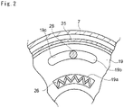
- a housing hole 19a is formed by individually penetrating the center plate 19, the input side plate 24, and output side plate 25 in an axial direction at the same radial positions, and as shown in Fig. 2 , a spring 26 that is compressible and stretchable in the circumferential direction is held in the hosing hole 19a thus formed. Accordingly, when a rotational speed of the integrated plates 24 and 25 is changed to be different from that of the center plate 19, the spring 19 is compressed in circumferential direction by the integrated plates 24 and 25 and the center plate 19. Therefore, the torque inputted to the integrated plates 24 and 25 can be transmitted to the center plate 19 while reducing the pulsations by elasticity of the spring 26. Thus, the spring 26 serves as the elastic damper.
- a sealing member 27 is interposed individually between the input side plate 24 and the center plate 19, and between the output side plate 25 and the center plate 19 in the radially outer side of the spring 26.
- a space A serving as the holding chamber of the present invention is formed by the sealing members 27 and the plates 24 and 25, and the space A is maintained in a dry condition by preventing the oil in the torque converter 1 from entering into the space A by the sealing members 27.
- a plurality of rolling members 28 held by the center plate 19 is arranged in the space A.
- a plurality of insertion holes 19b to which the rolling member 28 is inserted to be held in the space A is formed on the center plate 19 in the circumferential direction.
- both axial end portions of the rolling member 28 are formed to have outer diameters larger than a width of the insertion hole 19b formed on the center plate 19.
- an intermediate portion of the rolling member 28 whose outer diameter is smaller than that of the axial end portion is inserted into the insertion hole 19b.
- the insertion hole 19b has an arcuate inner face 19c on its outer circumferential side so that the rolling member 28 rolls along the inner face 19c. That is, the rolling member 28 is engaged with the center plate 19 while being allowed to rotate not only in the same direction but also relatively with the center plate 19. Specifically, the inner face 19c is formed in a manner such that a number of oscillations per rotation of the rolling member 28 is harmonized with a number of pulsations per rotation of the torque inputted to the front cover 7.
- the inner face 19c of the insertion hole 19b is formed in such a manner that a number of oscillations per rotation of the rolling member 28 is harmonized with a number of torque pulsations per rotation.
- a shape of a face being opposed to the inner face 19c is not limited to a specific configuration.
- both axial end portions of the rolling member 28 are formed to have outer diameters larger than the width of the insertion hole 19b.
- a shape of the rotary member 28 is also not limited to a specific configuration as long as being allowed to roll the insertion hole 19b.
- a surface of the rolling member 28 may be covered with resin.
- a sleeve is formed on the outer circumferential lateral face of the unit of the plates 24 and 25, and a spline engaged with the sleeves is formed on the outer circumferential end of the lockup piston 21. Therefore, the lockup piston 21 and the unit of the plates 24 and 25 are allowed to rotate integrally, and the lockup piston 21 is allowed to axially reciprocate toward and away from the plates 24 and 25.
- the torque converter 1 the torque is transmitted to the front cover 7 from the drive plate, and when the lockup clutch 20 is engaged with the front cover 7, the torque of the front cover 7 is transmitted to the lockup piston 21 through the friction plate 23. Since the lockup piston 21 is splined to the unit of the input side plate 24 and output side plate 25, the power transmitted to the lockup piston 21 is further transmitted to the plates 24 and 25. Consequently, the plates 24 and 25 are rotated integrally with the lockup piston 21. Then, the torque thus transmitted to the plates 24 and 25 is further transmitted to the center plate 19 through the spring 26. In this situation, the pulsation of the torque transmitted to the plates 24 and 25 are damped by the spring 26, and the torque is further transmitted from the center plate 19 to the output shaft 14 through the hub shaft 15. As a result, the center plate 19, the hub shaft 15 and the output shaft 14 are rotated integrally. In addition, since the hub shaft 15 is attached to the turbine runner 5 by a rivet 17, the turbine runner 5 is also rotated integrally with the center plate 19.
- pulsations of the torque of the rotary member rotated integrally with the center plate 19, that is, pulsations of the torque transmitted through the hub shaft 15, the turbine runner 5, the output shaft 14 and a not shown transmission connected with the output shaft 14 are damped by the oscillating motion of the rolling member 28. That is, the rotary member whose vibrations are damped by the rolling member 28 includes the hub shaft 15, the turbine runner 5, the output shaft 14 and the transmission connected with the output shaft 14.
- members forming the space A holding the rolling member 28, that is, the input side plate 24, the output side plate 25 and the sealing member 27 are excluded from the rotary member whose vibrations are damped by the rolling member 28.
- the mass (or mass ratio) of the rolling member 28 may be larger than that of the rotary member whose vibrations are damped by the rolling member 28. For this reason, the mass ratio is increased so that the vibration damping performance is enhanced.
- the mass inputted to the spring 26 is increased. Accordingly, an inertia moment of the rotary member of the input side of the spring 26 is increased.
- the input side plate 24, the output side plate 25 and the sealing member 27 are also allowed to serve as the mass damper for reducing the vibrations inputted to the spring 26. Consequently, the vibrations inputted to the rotary member can be suppressed efficiently by the rolling member 28.
- the vibration damping performance of the rotary member 28 may be enhanced.
- the present invention is applied to the hydraulic transmission comprising a driving member and driven member. Therefore, the present invention may also be applied to a hydraulic transmission comprising or a fluid coupling other than the foregoing torque converter having the torque amplifying function.
Landscapes
- Engineering & Computer Science (AREA)
- General Engineering & Computer Science (AREA)
- Mechanical Engineering (AREA)
- Physics & Mathematics (AREA)
- Acoustics & Sound (AREA)
- Aviation & Aerospace Engineering (AREA)
- Mechanical Operated Clutches (AREA)
- Vibration Dampers (AREA)
- Hydraulic Clutches, Magnetic Clutches, Fluid Clutches, And Fluid Joints (AREA)
Description
- This invention relates to a vibration damping device for reducing torsional vibrations, and especially to a vibration damping device comprising a rotary member rotated by torque and a rolling member held in the rotary member while being allowed to rotate relatively with the rotary member.
- A rotary member such as a drive shaft, gear and so on used to transmit a torque from a prime mover to a desired portion or a member is vibrated inevitably by a pulsation of the torque or load, or by a friction. A frequency of the vibration is varied according to rotational speed, and high order vibrations such as secondary vibrations are also generated. Therefore, amplitude of vibrations is widened by resonance. As a result, noise is generated and durability of the rotary member is degraded. Examples of a device or mechanism for suppressing such vibrations of equipment for transmitting power by rotation is disclosed in Japanese Patent Laid-Opens Nos.
2010-255853 11-311309 2011-208774 - Japanese Patent Laid-Open No.
2010-255853 2010-255853 2010-255853 2010-255853 - Meanwhile, Japanese Patent Laid-Open No.
11-311309 11-311309 11-311309 - In turn, Japanese Patent Laid-Open No.
2011-208774 2011-208774 - In order to downsize the torque converter, it is preferable to arrange the pendulum damper for suppressing the torque pulse inside of the torque converter. For example, provided that the pendulum damper taught by Japanese Patent Laid-Open No.
2010-255853 11-311309 - The vibration dampening performance of the pendulum damper is changed depending on a mass ratio of the rolling member to the rotary member. Specifically, the vibration dampening performance is improved by increasing a mass of the rolling member to be relatively larger than that of the rotary member. Therefore, if a housing holding the rolling member is integrated with the rotary member whose vibrations are damped by the pendulum damper, as taught by Japanese Patent Laid-Open No.
11-311309
The US patent documentUS 5 386 896 A discloses the features of the preamble ofclaim 1. - The present invention has been conceived noting the above-explained technical problems, and an object of the present invention is to improve a vibration damping performance of a damper of a vibration damping device having a chamber holding a rolling member.
- The vibration damping device of the present invention is applied to a power transmission unit having an input side rotary member that transmits a power to an elastic member, and an output rotary member that is rotated by the power transmitted from the elastic member. In order to damp vibrations of the output rotary member, the vibration damping device is provided with a holding chamber that is rotated integrally with the input side rotary member, and a rolling member that is held in the holding chamber in a manner to rotate in a same direction as the output side rotary member while being allowed to rotate relatively therewith.
- Specifically, the input side rotary member includes a covering member of a hydraulic transmission adapted to transmit power by a flow of fluid, and the output side rotary member includes a member rotated integrally with a driven side members rotated by the flow of the fluid. Meanwhile, the holding chamber is formed inside of the covering member, and sealed by a sealing member so as to prevent the fluid rotating the driven side member from entering into the holding chamber.
- The input side rotary member further includes a lockup clutch that transmits a torque inputted to the hydraulic transmission mechanically to an output member of the hydraulic transmission.
- The input side rotary member further includes an input side plate and an output side plate being opposed to each other in an axial direction. In addition, the lockup clutch is splined at least to any of an outer circumferential face of the input side plate and an outer circumferential face of the output side plate.
- According to the present invention, the power is transmitted from the input side rotary member to the output side rotary member through the elastic member. Therefore, pulsations of the torque transmitted to the output side rotary member can be suppressed by an elastic action of the elastic member. As described, the rolling member is held in the holding chamber in a manner to rotate in a same direction as the output side rotary member while being allowed to rotate relatively with the output side rotary member. Therefore, the holding chamber is rotated integrally with the member of the input side of the elastic member so that a mass of the rotary member whose vibrations are damped by an oscillating motion of the rolling member is reduced. As a result, the mass of the rolling member may become larger than that of the rotary member whose vibrations are damped by the oscillating motion of the rolling member. Therefore, the vibration damping performance of the oscillating rolling member is enhanced. In addition, since the mass of the holding chamber is added to the mass of the rotary member of the input side of the elastic member, an inertia moment of the rotary member of the input side of the elastic member can be increased. For this reason, vibration damping performance of the input side rotary member serving as a mass damper can be enhanced.
- As also described, the holding chamber is formed inside of the covering member of the hydraulic transmission, and the holding chamber is sealed by the sealing member so as to prevent the fluid from entering into the holding chamber. Therefore, an inner space of the holding chamber can be maintained in a dry condition so that the oscillating motion of the rolling member will not be impaired by viscosity resistance of the fluid. For this reason, the vibrating dampening performance of the oscillating rotary member will not be deteriorated. In addition, number of oscillations per rotation of the rolling member will not be changed.
-
-
Fig. 1 is a partial sectional view showing upper half of an example of the vibration damping device according to the present invention above a rotational center axis. -
Fig. 2 is a sectional view showing a cross-section along II-II line inFig. 1 . - Next a preferred example of the vibration damping device of the present invention will be explained in more detail. Referring now to
Fig. 1 , there is shown an example in which the vibration damping device is arranged in atorque converter 1 as a hydraulic transmission adapted to amplify a torque. Thetorque converter 1 shown therein is structured as a conventional torque converter widely used in vehicles. Specifically, a plurality ofpump blades 3 is arranged radially on an inner face of apump shell 4 of apump impeller 2 as an input side member, and aturbine runner 5 is arranged to be opposed thepump impeller 2. A configuration of theturbine runner 5 is substantially symmetrically with that of thepump impeller 2, and a plurality ofturbine blades 6 is arranged radially on an inner face of an annular (or semitorus-shape) shell. Thus, thepump impeller 2 and theturbine runner 5 are arranged coaxially while being opposed to each other. - A
front cover 7 covering theturbine runner 5 from outside is joined integrally with an outer circumferential end of thepump shell 4. As shown inFig. 1 , thefront cover 7 is a bottomed-cylindrical member comprising a front wall facing to the inner face of thepump shell 4, and oil is encapsulated inside of thefront cover 7. Thepump impeller 2 is rotated by the power transmitted thereto, and theturbine runner 5 is rotated to transmit the power by an oil flow in thefront cover 7 resulting from rotating theturbine runner 5. Acylindrical member 8 is formed in the center of thefront cover 7 to protrude outwardly from thefront cover 7, and a not shown output shaft of an engine is inserted into thecylindrical member 8. To this end, thefront cover 7 is fixed with a not shown drive plate that is rotated integrally with the output shaft of the engine, at a plurality of outer circumferential portions by a plurality of nuts 9. Therefore, thefront cover 7 is rotated together with the drive plate by the power from the output shaft. - A
cylindrical shaft 10 is joined integrally with an inner circumferential end of thepump shell 4. Thecylindrical shaft 10 extends toward a back side (i.e., toward an opposite side of the engine), and connected with an oil pump not shown. In addition, a fixedshaft 11 is inserted into thecylindrical shaft 10. Specifically, an outer diameter of the fixedshaft 11 is smaller than an inner diameter of thecylindrical shaft 10, and a leading end portion of the fixedshaft 11 is inserted into an inner space of thetorque converter 1 enclosed by thepump shell 4 and thefront cover 7. - More specifically, the leading end portion of the fixed
shaft 11 is situated at an inner circumferential side of theturbine runner 5 between thepump impeller 2 and theturbine runner 5, and splined to an inner race of a one-way clutch 12. In addition, astator 13 is arranged between an inner circumferential portion of thepump impeller 2 and an inner circumferential portion of theturbine runner 5, and thestator 13 is fitted onto an outer race of the one-way clutch 12. Therefore, provided that a ratio between a speed of thepump impeller 2 and a speed of theturbine runner 5 is small, a rotation of thestator 13 can be stopped by the one-way clutch 12 even if the oil flowing out of theturbine runner 5 acts on thestator 13. As a result, a flowing direction of the oil is changed to a direction to deliver the oil to thepump impeller 2. By contrast, provided that the ratio between the speed of thepump impeller 2 and the speed of theturbine runner 5 becomes large, the oil is poured to a back face of thestator 13. In this situation, therefore, thestator 13 is rotated in order not to disturb the flow of the oil. - An output shaft 14 (i.e., an input shaft of not shown transmission) is inserted into the fixed
shaft 11 in a rotatable manner. A leading end portion of theoutput shaft 14 protrudes from the leading end of the fixedshaft 11 to the vicinity of an inner face of thefront cover 7 so that the protruding portion of theoutput shaft 14 is splined to ahub shaft 15. On thehub shaft 15, a flange-shapedhub 16 is formed to protrude outwardly to be connected integrally with theturbine runner 5 by arivet 17. - A
cylindrical portion 18 is formed by bending the outer circumferential portion of thehub 16 toward the engine side, and anannular center plate 19 serving as the output side rotary member of the invention is attached to an outer circumferential face of thecylindrical portion 18. Specifically, thecenter plate 19 has a hole in its center and fitted onto thecylindrical portion 18. - A
lockup clutch 20 is fitted onto thehub shaft 15 between thehub 16 and thefront cover 7. As the conventional lockup clutch, thelockup clutch 20 is adapted to reciprocate in an axial direction depending on a pressure difference between front and rear faces of a piston thereof. Specifically, thelockup clutch 20 is comprised of anannular lockup piston 21, ahub portion 22 formed by bending an inner circumferential portion of thelockup piston 21 toward the engine to be fitted onto thehub shaft 15 while being allowed to rotate relatively with thehub shaft 15, and afriction plate 23 formed on an outer circumferential side of an outer surface of thelockup piston 21 being opposed to thefront cover 7. Thelockup piston 21 is moved toward thefront cover 7 by lowering an oil pressure between thelockup piston 21 and thefront cover 7 so that thefriction plate 23 is contacted with the inner face of thefront cover 7. Consequently, thelockup piston 21 is physically connected with thefront cover 7 to transmit the power inputted to thefront cover 7 directly to thelockup piston 21. Thelockup clutch 20 is engaged when a ratio between an input speed and an output speed of thetorque converter 1 is "1", that is, thelockup clutch 20 is engaged under the condition that the vehicle having thetorque converter 1 is driven steadily. - An annular
input side plate 24 is attached to a surface of thecenter plate 19 facing to the engine, and a bottomed-cylindricaloutput side plate 25 is attached to a surface of thecenter plate 19 facing to theturbine runner 5. Thus, theinput side plate 24 and theoutput side plate 25 are situated across thecenter plate 19. In order to close an opening of theoutput side plate 25, an outer circumferential end of theinput side plate 24 is connected with an outer circumferential end of theoutput side plate 25. Both of theinput side plate 24 and theoutput side plate 25 thus integrated are fitted onto thecylindrical portion 18 while being allowed to rotate relatively therewith. Therefore, theinput side plate 24 andoutput side plate 25 are rotated integrally while being allowed to rotate relatively with thecenter plate 19. Accordingly, theinput side plate 24 andoutput side plate 25 serve as the input side rotary member of the present invention, and also serve as a housing for holding an after-mentioned rollingmember 28 therein. - A
housing hole 19a is formed by individually penetrating thecenter plate 19, theinput side plate 24, andoutput side plate 25 in an axial direction at the same radial positions, and as shown inFig. 2 , aspring 26 that is compressible and stretchable in the circumferential direction is held in thehosing hole 19a thus formed. Accordingly, when a rotational speed of theintegrated plates center plate 19, thespring 19 is compressed in circumferential direction by theintegrated plates center plate 19. Therefore, the torque inputted to theintegrated plates center plate 19 while reducing the pulsations by elasticity of thespring 26. Thus, thespring 26 serves as the elastic damper. - A sealing
member 27 is interposed individually between theinput side plate 24 and thecenter plate 19, and between theoutput side plate 25 and thecenter plate 19 in the radially outer side of thespring 26. Thus, a space A serving as the holding chamber of the present invention is formed by the sealingmembers 27 and theplates torque converter 1 from entering into the space A by the sealingmembers 27. - A plurality of rolling
members 28 held by thecenter plate 19 is arranged in the space A. Specifically, a plurality ofinsertion holes 19b to which the rollingmember 28 is inserted to be held in the space A is formed on thecenter plate 19 in the circumferential direction. In order to prevent an disengagement of the rollingmember 28 from theinsertion hole 19b, both axial end portions of the rollingmember 28 are formed to have outer diameters larger than a width of theinsertion hole 19b formed on thecenter plate 19. In other words, an intermediate portion of the rollingmember 28 whose outer diameter is smaller than that of the axial end portion is inserted into theinsertion hole 19b. - The
insertion hole 19b has an arcuateinner face 19c on its outer circumferential side so that the rollingmember 28 rolls along theinner face 19c. That is, the rollingmember 28 is engaged with thecenter plate 19 while being allowed to rotate not only in the same direction but also relatively with thecenter plate 19. Specifically, theinner face 19c is formed in a manner such that a number of oscillations per rotation of the rollingmember 28 is harmonized with a number of pulsations per rotation of the torque inputted to thefront cover 7. To this end, theinner face 19c of theinsertion hole 19b is formed in such a manner that a square root of a value obtained by dividing a distance R between an oscillation center of therotational member 28 and a rotational center of thehub shaft 18 by a distance L between a gravity center of the rollingmember 28 and the oscillation center of therotational member 28 is conformed to a number of pulsations per rotation "n" of the torque inputted to thefront cover 7, as expressed by the following expression:
- Thus, in order to counteract the torque pulsations by the oscillating motion of the rolling
member 28, theinner face 19c of theinsertion hole 19b is formed in such a manner that a number of oscillations per rotation of the rollingmember 28 is harmonized with a number of torque pulsations per rotation. However, a shape of a face being opposed to theinner face 19c is not limited to a specific configuration. As described, in order to prevent an disengagement of the rollingmember 28 from theinsertion hole 19b, both axial end portions of the rollingmember 28 are formed to have outer diameters larger than the width of theinsertion hole 19b. However, a shape of therotary member 28 is also not limited to a specific configuration as long as being allowed to roll theinsertion hole 19b. Optionally, in order to allow the rollingmember 28 to oscillate along theinner face 19c of theinsertion hole 19b smoothly, a surface of the rollingmember 28 may be covered with resin. To this end, alternatively, it is also possible to apply grease to the outer circumferential face of the rollingmember 28 or to theinner face 19c of theinsertion face 19b. - A sleeve is formed on the outer circumferential lateral face of the unit of the
plates lockup piston 21. Therefore, thelockup piston 21 and the unit of theplates lockup piston 21 is allowed to axially reciprocate toward and away from theplates - In the
torque converter 1, the torque is transmitted to thefront cover 7 from the drive plate, and when thelockup clutch 20 is engaged with thefront cover 7, the torque of thefront cover 7 is transmitted to thelockup piston 21 through thefriction plate 23. Since thelockup piston 21 is splined to the unit of theinput side plate 24 andoutput side plate 25, the power transmitted to thelockup piston 21 is further transmitted to theplates plates lockup piston 21. Then, the torque thus transmitted to theplates center plate 19 through thespring 26. In this situation, the pulsation of the torque transmitted to theplates spring 26, and the torque is further transmitted from thecenter plate 19 to theoutput shaft 14 through thehub shaft 15. As a result, thecenter plate 19, thehub shaft 15 and theoutput shaft 14 are rotated integrally. In addition, since thehub shaft 15 is attached to theturbine runner 5 by arivet 17, theturbine runner 5 is also rotated integrally with thecenter plate 19. - Meanwhile, pulsations of the torque of the rotary member rotated integrally with the
center plate 19, that is, pulsations of the torque transmitted through thehub shaft 15, theturbine runner 5, theoutput shaft 14 and a not shown transmission connected with theoutput shaft 14 are damped by the oscillating motion of the rollingmember 28. That is, the rotary member whose vibrations are damped by the rollingmember 28 includes thehub shaft 15, theturbine runner 5, theoutput shaft 14 and the transmission connected with theoutput shaft 14. Thus, members forming the space A holding the rollingmember 28, that is, theinput side plate 24, theoutput side plate 25 and the sealingmember 27 are excluded from the rotary member whose vibrations are damped by the rollingmember 28. - This means that a total mass of the
input side plate 24, theoutput side plate 25 and the sealingmember 27 is deducted from a mass of the rotary member whose vibrations are damped by the rollingmember 28. Therefore, the mass (or mass ratio) of the rollingmember 28 may be larger than that of the rotary member whose vibrations are damped by the rollingmember 28. For this reason, the mass ratio is increased so that the vibration damping performance is enhanced. In addition, since theinput side plate 24, theoutput side plate 25, the sealingmember 27 and thefront cover 7 are rotated integrally, the mass inputted to thespring 26 is increased. Accordingly, an inertia moment of the rotary member of the input side of thespring 26 is increased. Therefore, theinput side plate 24, theoutput side plate 25 and the sealingmember 27 are also allowed to serve as the mass damper for reducing the vibrations inputted to thespring 26. Consequently, the vibrations inputted to the rotary member can be suppressed efficiently by the rollingmember 28. - In addition, since the oil is not delivered to the space A in which the rolling
member 28 oscillates, the oscillating motion of the rollingmember 28 will not be impaired by the viscosity of the oil. Therefore, the vibration damping performance of therotary member 28 may be enhanced. - The present invention is applied to the hydraulic transmission comprising a driving member and driven member. Therefore, the present invention may also be applied to a hydraulic transmission comprising or a fluid coupling other than the foregoing torque converter having the torque amplifying function.
Claims (4)
- A vibration damping device, which is applied to a power transmission unit having an input side rotary member (24, 25) that transmits a power to an elastic member (26) and an output side rotary member (19) that is rotated by the power transmitted from the elastic member (26), and that is adapted to damp vibrations of the output rotary member (19),a holding chamber (A) that is formed of a housing rotated integrally with the input side rotary member (24, 25);the input side rotary member (24, 25) includes an input side plate (24) and an output side plate (25),the output side rotary member (19) includes a center plate (19),a housing hole (19a) is formed by individually penetrating the center plate (19), the input side plate (24) and the output side plate (25) in an axial direction at the same radial positions,the elastic member (26) is compressible and stretchable in the circumferential direction and held in the housing hole (19a),characterized in thata rolling member (28) that is inserted into an insertion hole (19b) having an arcuate inner face (19c) on its outer circumferential side and formed on the output side rotary member (19) to be held in the holding chamber (A) in a manner to rotate in a same direction as the output side rotary member (19) while being allowed to rotate relatively therewith along the inner face (19c) of the insertion hole (19b).
- The vibration damping device as claimed in claim 1,wherein the input side rotary member (24, 25) includes a covering member (7) of a hydraulic transmission (1) adapted to transmit power by a flow of fluid;wherein the output side rotary member (19) includes a member (18) rotated integrally with a driven side member (5) rotated by the flow of the fluid;wherein the holding chamber (A) is formed inside of the covering member (7); andwherein the holding chamber (A) is sealed by a sealing member (27) to prevent the fluid rotating the driven side member (5) from entering into the holding chamber (A).
- The vibration damping device as claimed in claim 2, wherein the input side rotary member (24, 25) includes a lockup clutch (20) that transmits an input torque of the hydraulic transmission (1) mechanically to an output member of the hydraulic transmission (1).
- The vibration damping device as claimed in claim 3,wherein the input side rotary member (24, 25) includes the input side plate (24) and the output side plate (25) being opposed to each other in an axial direction; andwherein the lockup clutch (20) is splined at least to any of an outer circumferential face of the input side plate (24) and an outer circumferential face of the output side plate (25).
Applications Claiming Priority (1)
| Application Number | Priority Date | Filing Date | Title |
|---|---|---|---|
| PCT/JP2012/055031 WO2013128590A1 (en) | 2012-02-29 | 2012-02-29 | Vibration reduction device |
Publications (4)
| Publication Number | Publication Date |
|---|---|
| EP2821669A1 EP2821669A1 (en) | 2015-01-07 |
| EP2821669A4 EP2821669A4 (en) | 2016-04-13 |
| EP2821669B1 EP2821669B1 (en) | 2018-07-04 |
| EP2821669B2 true EP2821669B2 (en) | 2023-02-22 |
Family
ID=49081840
Family Applications (1)
| Application Number | Title | Priority Date | Filing Date |
|---|---|---|---|
| EP12870149.7A Not-in-force EP2821669B2 (en) | 2012-02-29 | 2012-02-29 | Vibration reduction device |
Country Status (5)
| Country | Link |
|---|---|
| US (1) | US9416860B2 (en) |
| EP (1) | EP2821669B2 (en) |
| JP (1) | JP5850132B2 (en) |
| CN (1) | CN104136802B (en) |
| WO (1) | WO2013128590A1 (en) |
Families Citing this family (17)
| Publication number | Priority date | Publication date | Assignee | Title |
|---|---|---|---|---|
| DE102012213105A1 (en) * | 2011-08-23 | 2013-02-28 | Schaeffler Technologies AG & Co. KG | Torque transfer device |
| JP5900469B2 (en) | 2013-11-22 | 2016-04-06 | トヨタ自動車株式会社 | Vibration reduction device |
| JP6542220B2 (en) * | 2013-12-02 | 2019-07-10 | シェフラー テクノロジーズ アー・ゲー ウント コー. カー・ゲーSchaeffler Technologies AG & Co. KG | Device for transmitting torque |
| CN105899843B (en) * | 2014-01-08 | 2018-04-03 | 丰田自动车株式会社 | Twisting vibration reduces device |
| JP5999144B2 (en) | 2014-06-25 | 2016-09-28 | トヨタ自動車株式会社 | Torsional vibration reduction device |
| JP5900541B2 (en) * | 2014-06-27 | 2016-04-06 | トヨタ自動車株式会社 | Torque converter with torsional vibration reduction device |
| JP2016011702A (en) | 2014-06-27 | 2016-01-21 | トヨタ自動車株式会社 | Vibration reduction device |
| JP5791772B1 (en) * | 2014-08-29 | 2015-10-07 | 株式会社エクセディ | Fluid power transmission device |
| DE102014220897A1 (en) * | 2014-10-15 | 2016-04-21 | Zf Friedrichshafen Ag | Coupling arrangement with a vibration reduction device and with a coupling device |
| JP6554819B2 (en) * | 2015-02-27 | 2019-08-07 | アイシン精機株式会社 | Vibration absorber |
| JP6260556B2 (en) * | 2015-03-03 | 2018-01-17 | トヨタ自動車株式会社 | Torsional vibration reduction device |
| JP6314888B2 (en) * | 2015-03-30 | 2018-04-25 | トヨタ自動車株式会社 | Torsional vibration reduction device |
| DE102015215889A1 (en) * | 2015-08-20 | 2017-02-23 | Schaeffler Technologies AG & Co. KG | Centrifugal pendulum and hydrodynamic torque converter with centrifugal pendulum |
| JP6361617B2 (en) * | 2015-09-14 | 2018-07-25 | トヨタ自動車株式会社 | Torsional vibration reduction device |
| JP2018009614A (en) * | 2016-07-12 | 2018-01-18 | 株式会社エクセディ | Damper gear |
| DE102018122677A1 (en) * | 2018-09-17 | 2020-03-19 | Schaeffler Technologies AG & Co. KG | Torsional vibration damper |
| DE102018122661A1 (en) * | 2018-09-17 | 2020-03-19 | Schaeffler Technologies AG & Co. KG | Torsional vibration damper |
Citations (7)
| Publication number | Priority date | Publication date | Assignee | Title |
|---|---|---|---|---|
| EP1744074A2 (en) † | 2005-07-11 | 2007-01-17 | LuK Lamellen und Kupplungsbau Beteiligungs KG | Torque transfer device |
| DE102009033864A1 (en) † | 2008-07-31 | 2010-02-04 | Luk Lamellen Und Kupplungsbau Beteiligungs Kg | Two-mass flywheel for use in crankshaft of internal-combustion engine, is provided with inlet part with primary flywheel mass |
| WO2010037661A1 (en) † | 2008-09-30 | 2010-04-08 | Zf Friedrichshafen Ag | Wet starting clutch |
| US20100269497A1 (en) † | 2009-04-27 | 2010-10-28 | Luk Lamellen Und Kupplungsbau Beteiligungs Kg | Hydrodynamic torque converter |
| DE102010025582A1 (en) † | 2009-07-16 | 2011-01-20 | Luk Lamellen Und Kupplungsbau Beteiligungs Kg | Torque transfer device |
| DE102010054296A1 (en) † | 2009-12-22 | 2011-06-30 | Schaeffler Technologies GmbH & Co. KG, 91074 | Torque transmission device, has mass pendulum guided into slotted holes of secondary flange using bolt, and intermediate plate arranged between pendulum masses and including projection projected into recess of secondary flange |
| US20110179782A1 (en) † | 2008-06-02 | 2011-07-28 | Schaeffler Technologies Gmbh & Co. Kg | Rotary vibration damper with centrifugal force pendulum |
Family Cites Families (19)
| Publication number | Priority date | Publication date | Assignee | Title |
|---|---|---|---|---|
| DE3132045A1 (en) * | 1981-08-13 | 1983-03-03 | Fichtel & Sachs Ag, 8720 Schweinfurt | Torsional vibration damper with switchable idle damper |
| US5355747A (en) * | 1991-09-04 | 1994-10-18 | Kabushiki Kaisha Daikin Seisakusho | Flywheel assembly |
| US5386896A (en) * | 1992-07-06 | 1995-02-07 | Kabushiki Kaisha Daikin Seisakusho | Torsional vibration damping device and lock-up clutch in torque converter |
| JP3322709B2 (en) | 1992-12-14 | 2002-09-09 | エヌエスケー・ワーナー株式会社 | Damper device for lock-up clutch for torque converter |
| JP2595618Y2 (en) * | 1993-07-16 | 1999-05-31 | 株式会社エクセディ | Torsional converter damping device for torsional vibration |
| DE19517605C2 (en) * | 1994-05-25 | 1997-09-18 | Volkswagen Ag | Device for compensating for alternating torques and vibrations in the drive train of a motor vehicle |
| GB9603269D0 (en) * | 1996-02-16 | 1996-04-17 | Automotive Products Plc | A power transmitting arrangement |
| US5941133A (en) * | 1996-04-19 | 1999-08-24 | Eti Technologies Inc. | Torsional and translational vibration removing device |
| DE19635797C2 (en) * | 1996-06-12 | 2003-02-27 | Zf Sachs Ag | Torsional vibration damper with rolling elements as coupling elements |
| ES2190679B1 (en) * | 1997-05-09 | 2004-11-16 | Mannesmann Sachs Ag | CLUTCH OF FRICTION WITH A COMPENSATION SYSTEM. |
| JPH11311309A (en) | 1998-04-30 | 1999-11-09 | Unisia Jecs Corp | Torque converter |
| DE10000899A1 (en) * | 2000-01-12 | 2001-07-19 | Mannesmann Sachs Ag | Torsional vibration damper for coupling turbine wheel hub with turbine wheel shell in hydrodynamic clutch device and/or for coupling lockup clutch arrangement with turbine wheel |
| KR20080065649A (en) * | 2005-11-10 | 2008-07-14 | 루크 라멜렌 운트 쿠프룽스바우 베타일리궁스 카게 | Torsional Vibration Damper and Hydrodynamic Torque Converter for Vehicle Drive Train |
| JP2007255636A (en) | 2006-03-24 | 2007-10-04 | Valeo Unisia Transmission Kk | Torque converter device |
| FR2922619B1 (en) * | 2007-10-17 | 2010-03-19 | Valeo Embrayages | HYDROKINETIC COUPLING DEVICE COMPRISING A MULTI-DISC LATCH CLUTCH EQUIPPED WITH ELASTIC CIRCONFERENTIAL PRECONTRAIN MEANS |
| DE112008003168B4 (en) * | 2007-11-29 | 2022-01-05 | Schaeffler Technologies AG & Co. KG | Power transmission device, in particular for power transmission between a drive machine and an output |
| WO2010020209A1 (en) * | 2008-08-21 | 2010-02-25 | Luk Lamellen Und Kupplungsbau Beteiligungs Kg | Torsional vibration damper |
| WO2011077478A1 (en) * | 2009-12-22 | 2011-06-30 | トヨタ自動車株式会社 | Lockup clutch mechanism |
| JP5316461B2 (en) | 2010-03-30 | 2013-10-16 | トヨタ自動車株式会社 | Vibration reduction device |
-
2012
- 2012-02-29 US US14/362,332 patent/US9416860B2/en not_active Expired - Fee Related
- 2012-02-29 CN CN201280070749.2A patent/CN104136802B/en not_active Expired - Fee Related
- 2012-02-29 EP EP12870149.7A patent/EP2821669B2/en not_active Not-in-force
- 2012-02-29 JP JP2014501894A patent/JP5850132B2/en not_active Expired - Fee Related
- 2012-02-29 WO PCT/JP2012/055031 patent/WO2013128590A1/en not_active Ceased
Patent Citations (7)
| Publication number | Priority date | Publication date | Assignee | Title |
|---|---|---|---|---|
| EP1744074A2 (en) † | 2005-07-11 | 2007-01-17 | LuK Lamellen und Kupplungsbau Beteiligungs KG | Torque transfer device |
| US20110179782A1 (en) † | 2008-06-02 | 2011-07-28 | Schaeffler Technologies Gmbh & Co. Kg | Rotary vibration damper with centrifugal force pendulum |
| DE102009033864A1 (en) † | 2008-07-31 | 2010-02-04 | Luk Lamellen Und Kupplungsbau Beteiligungs Kg | Two-mass flywheel for use in crankshaft of internal-combustion engine, is provided with inlet part with primary flywheel mass |
| WO2010037661A1 (en) † | 2008-09-30 | 2010-04-08 | Zf Friedrichshafen Ag | Wet starting clutch |
| US20100269497A1 (en) † | 2009-04-27 | 2010-10-28 | Luk Lamellen Und Kupplungsbau Beteiligungs Kg | Hydrodynamic torque converter |
| DE102010025582A1 (en) † | 2009-07-16 | 2011-01-20 | Luk Lamellen Und Kupplungsbau Beteiligungs Kg | Torque transfer device |
| DE102010054296A1 (en) † | 2009-12-22 | 2011-06-30 | Schaeffler Technologies GmbH & Co. KG, 91074 | Torque transmission device, has mass pendulum guided into slotted holes of secondary flange using bolt, and intermediate plate arranged between pendulum masses and including projection projected into recess of secondary flange |
Also Published As
| Publication number | Publication date |
|---|---|
| EP2821669B1 (en) | 2018-07-04 |
| CN104136802A (en) | 2014-11-05 |
| CN104136802B (en) | 2016-01-20 |
| US20140374207A1 (en) | 2014-12-25 |
| EP2821669A1 (en) | 2015-01-07 |
| JPWO2013128590A1 (en) | 2015-07-30 |
| JP5850132B2 (en) | 2016-02-03 |
| EP2821669A4 (en) | 2016-04-13 |
| WO2013128590A1 (en) | 2013-09-06 |
| US9416860B2 (en) | 2016-08-16 |
Similar Documents
| Publication | Publication Date | Title |
|---|---|---|
| EP2821669B2 (en) | Vibration reduction device | |
| EP2843262B1 (en) | Vibration damping device | |
| US10288158B2 (en) | Fluid transmission device for vehicle | |
| US9982765B2 (en) | Fluid coupling | |
| KR101358998B1 (en) | Torque converter for vehicle | |
| JP6384573B1 (en) | Torsional vibration reduction device | |
| EP2818753A1 (en) | Torsional vibration damping device | |
| JP2009041662A (en) | Torque converter with lock-up clutch | |
| US20150090555A1 (en) | Power transmission system | |
| US10400873B2 (en) | Torsional vibration damper | |
| JP6344328B2 (en) | Fluid transmission device | |
| US10533650B2 (en) | Torsional vibration damper | |
| JP6344326B2 (en) | Fluid transmission device | |
| CN113757336A (en) | Torque damper device and torque converter | |
| JP6492916B2 (en) | Torsional vibration reduction device | |
| JP5598367B2 (en) | Torsional vibration reduction device | |
| JP2009103265A (en) | Power transmission device | |
| JP2019100497A (en) | Torsional vibration reduction device | |
| JP2012180907A (en) | Torsional vibration damping device | |
| JP2012225378A (en) | Torsional vibration reducing device | |
| JPH08226520A (en) | Lockup clutch of torque converter |
Legal Events
| Date | Code | Title | Description |
|---|---|---|---|
| PUAI | Public reference made under article 153(3) epc to a published international application that has entered the european phase |
Free format text: ORIGINAL CODE: 0009012 |
|
| 17P | Request for examination filed |
Effective date: 20140611 |
|
| AK | Designated contracting states |
Kind code of ref document: A1 Designated state(s): AL AT BE BG CH CY CZ DE DK EE ES FI FR GB GR HR HU IE IS IT LI LT LU LV MC MK MT NL NO PL PT RO RS SE SI SK SM TR |
|
| AX | Request for extension of the european patent |
Extension state: BA ME |
|
| DAX | Request for extension of the european patent (deleted) | ||
| RA4 | Supplementary search report drawn up and despatched (corrected) |
Effective date: 20160310 |
|
| RIC1 | Information provided on ipc code assigned before grant |
Ipc: F16H 45/02 20060101ALI20160304BHEP Ipc: F16D 33/18 20060101ALI20160304BHEP Ipc: F16F 15/14 20060101AFI20160304BHEP |
|
| GRAP | Despatch of communication of intention to grant a patent |
Free format text: ORIGINAL CODE: EPIDOSNIGR1 |
|
| STAA | Information on the status of an ep patent application or granted ep patent |
Free format text: STATUS: GRANT OF PATENT IS INTENDED |
|
| INTG | Intention to grant announced |
Effective date: 20171213 |
|
| GRAS | Grant fee paid |
Free format text: ORIGINAL CODE: EPIDOSNIGR3 |
|
| GRAJ | Information related to disapproval of communication of intention to grant by the applicant or resumption of examination proceedings by the epo deleted |
Free format text: ORIGINAL CODE: EPIDOSDIGR1 |
|
| GRAL | Information related to payment of fee for publishing/printing deleted |
Free format text: ORIGINAL CODE: EPIDOSDIGR3 |
|
| STAA | Information on the status of an ep patent application or granted ep patent |
Free format text: STATUS: REQUEST FOR EXAMINATION WAS MADE |
|
| GRAR | Information related to intention to grant a patent recorded |
Free format text: ORIGINAL CODE: EPIDOSNIGR71 |
|
| STAA | Information on the status of an ep patent application or granted ep patent |
Free format text: STATUS: GRANT OF PATENT IS INTENDED |
|
| GRAA | (expected) grant |
Free format text: ORIGINAL CODE: 0009210 |
|
| STAA | Information on the status of an ep patent application or granted ep patent |
Free format text: STATUS: THE PATENT HAS BEEN GRANTED |
|
| INTC | Intention to grant announced (deleted) | ||
| AK | Designated contracting states |
Kind code of ref document: B1 Designated state(s): AL AT BE BG CH CY CZ DE DK EE ES FI FR GB GR HR HU IE IS IT LI LT LU LV MC MK MT NL NO PL PT RO RS SE SI SK SM TR |
|
| INTG | Intention to grant announced |
Effective date: 20180525 |
|
| REG | Reference to a national code |
Ref country code: GB Ref legal event code: FG4D |
|
| REG | Reference to a national code |
Ref country code: CH Ref legal event code: EP |
|
| REG | Reference to a national code |
Ref country code: AT Ref legal event code: REF Ref document number: 1014858 Country of ref document: AT Kind code of ref document: T Effective date: 20180715 |
|
| REG | Reference to a national code |
Ref country code: IE Ref legal event code: FG4D |
|
| REG | Reference to a national code |
Ref country code: DE Ref legal event code: R096 Ref document number: 602012048240 Country of ref document: DE |
|
| REG | Reference to a national code |
Ref country code: NL Ref legal event code: MP Effective date: 20180704 |
|
| REG | Reference to a national code |
Ref country code: LT Ref legal event code: MG4D |
|
| REG | Reference to a national code |
Ref country code: DE Ref legal event code: R084 Ref document number: 602012048240 Country of ref document: DE |
|
| REG | Reference to a national code |
Ref country code: AT Ref legal event code: MK05 Ref document number: 1014858 Country of ref document: AT Kind code of ref document: T Effective date: 20180704 |
|
| PG25 | Lapsed in a contracting state [announced via postgrant information from national office to epo] |
Ref country code: NL Free format text: LAPSE BECAUSE OF FAILURE TO SUBMIT A TRANSLATION OF THE DESCRIPTION OR TO PAY THE FEE WITHIN THE PRESCRIBED TIME-LIMIT Effective date: 20180704 |
|
| PG25 | Lapsed in a contracting state [announced via postgrant information from national office to epo] |
Ref country code: LT Free format text: LAPSE BECAUSE OF FAILURE TO SUBMIT A TRANSLATION OF THE DESCRIPTION OR TO PAY THE FEE WITHIN THE PRESCRIBED TIME-LIMIT Effective date: 20180704 Ref country code: RS Free format text: LAPSE BECAUSE OF FAILURE TO SUBMIT A TRANSLATION OF THE DESCRIPTION OR TO PAY THE FEE WITHIN THE PRESCRIBED TIME-LIMIT Effective date: 20180704 Ref country code: FI Free format text: LAPSE BECAUSE OF FAILURE TO SUBMIT A TRANSLATION OF THE DESCRIPTION OR TO PAY THE FEE WITHIN THE PRESCRIBED TIME-LIMIT Effective date: 20180704 Ref country code: SE Free format text: LAPSE BECAUSE OF FAILURE TO SUBMIT A TRANSLATION OF THE DESCRIPTION OR TO PAY THE FEE WITHIN THE PRESCRIBED TIME-LIMIT Effective date: 20180704 Ref country code: PL Free format text: LAPSE BECAUSE OF FAILURE TO SUBMIT A TRANSLATION OF THE DESCRIPTION OR TO PAY THE FEE WITHIN THE PRESCRIBED TIME-LIMIT Effective date: 20180704 Ref country code: CZ Free format text: LAPSE BECAUSE OF FAILURE TO SUBMIT A TRANSLATION OF THE DESCRIPTION OR TO PAY THE FEE WITHIN THE PRESCRIBED TIME-LIMIT Effective date: 20180704 Ref country code: BG Free format text: LAPSE BECAUSE OF FAILURE TO SUBMIT A TRANSLATION OF THE DESCRIPTION OR TO PAY THE FEE WITHIN THE PRESCRIBED TIME-LIMIT Effective date: 20181004 Ref country code: GR Free format text: LAPSE BECAUSE OF FAILURE TO SUBMIT A TRANSLATION OF THE DESCRIPTION OR TO PAY THE FEE WITHIN THE PRESCRIBED TIME-LIMIT Effective date: 20181005 Ref country code: IS Free format text: LAPSE BECAUSE OF FAILURE TO SUBMIT A TRANSLATION OF THE DESCRIPTION OR TO PAY THE FEE WITHIN THE PRESCRIBED TIME-LIMIT Effective date: 20181104 Ref country code: NO Free format text: LAPSE BECAUSE OF FAILURE TO SUBMIT A TRANSLATION OF THE DESCRIPTION OR TO PAY THE FEE WITHIN THE PRESCRIBED TIME-LIMIT Effective date: 20181004 Ref country code: AT Free format text: LAPSE BECAUSE OF FAILURE TO SUBMIT A TRANSLATION OF THE DESCRIPTION OR TO PAY THE FEE WITHIN THE PRESCRIBED TIME-LIMIT Effective date: 20180704 |
|
| PG25 | Lapsed in a contracting state [announced via postgrant information from national office to epo] |
Ref country code: HR Free format text: LAPSE BECAUSE OF FAILURE TO SUBMIT A TRANSLATION OF THE DESCRIPTION OR TO PAY THE FEE WITHIN THE PRESCRIBED TIME-LIMIT Effective date: 20180704 Ref country code: ES Free format text: LAPSE BECAUSE OF FAILURE TO SUBMIT A TRANSLATION OF THE DESCRIPTION OR TO PAY THE FEE WITHIN THE PRESCRIBED TIME-LIMIT Effective date: 20180704 Ref country code: AL Free format text: LAPSE BECAUSE OF FAILURE TO SUBMIT A TRANSLATION OF THE DESCRIPTION OR TO PAY THE FEE WITHIN THE PRESCRIBED TIME-LIMIT Effective date: 20180704 Ref country code: LV Free format text: LAPSE BECAUSE OF FAILURE TO SUBMIT A TRANSLATION OF THE DESCRIPTION OR TO PAY THE FEE WITHIN THE PRESCRIBED TIME-LIMIT Effective date: 20180704 |
|
| REG | Reference to a national code |
Ref country code: DE Ref legal event code: R026 Ref document number: 602012048240 Country of ref document: DE |
|
| PLBI | Opposition filed |
Free format text: ORIGINAL CODE: 0009260 |
|
| PLAX | Notice of opposition and request to file observation + time limit sent |
Free format text: ORIGINAL CODE: EPIDOSNOBS2 |
|
| PG25 | Lapsed in a contracting state [announced via postgrant information from national office to epo] |
Ref country code: RO Free format text: LAPSE BECAUSE OF FAILURE TO SUBMIT A TRANSLATION OF THE DESCRIPTION OR TO PAY THE FEE WITHIN THE PRESCRIBED TIME-LIMIT Effective date: 20180704 Ref country code: IT Free format text: LAPSE BECAUSE OF FAILURE TO SUBMIT A TRANSLATION OF THE DESCRIPTION OR TO PAY THE FEE WITHIN THE PRESCRIBED TIME-LIMIT Effective date: 20180704 Ref country code: EE Free format text: LAPSE BECAUSE OF FAILURE TO SUBMIT A TRANSLATION OF THE DESCRIPTION OR TO PAY THE FEE WITHIN THE PRESCRIBED TIME-LIMIT Effective date: 20180704 |
|
| 26 | Opposition filed |
Opponent name: VALEO EMBRAYAGES Effective date: 20190404 |
|
| PG25 | Lapsed in a contracting state [announced via postgrant information from national office to epo] |
Ref country code: SK Free format text: LAPSE BECAUSE OF FAILURE TO SUBMIT A TRANSLATION OF THE DESCRIPTION OR TO PAY THE FEE WITHIN THE PRESCRIBED TIME-LIMIT Effective date: 20180704 Ref country code: DK Free format text: LAPSE BECAUSE OF FAILURE TO SUBMIT A TRANSLATION OF THE DESCRIPTION OR TO PAY THE FEE WITHIN THE PRESCRIBED TIME-LIMIT Effective date: 20180704 Ref country code: SM Free format text: LAPSE BECAUSE OF FAILURE TO SUBMIT A TRANSLATION OF THE DESCRIPTION OR TO PAY THE FEE WITHIN THE PRESCRIBED TIME-LIMIT Effective date: 20180704 |
|
| PG25 | Lapsed in a contracting state [announced via postgrant information from national office to epo] |
Ref country code: SI Free format text: LAPSE BECAUSE OF FAILURE TO SUBMIT A TRANSLATION OF THE DESCRIPTION OR TO PAY THE FEE WITHIN THE PRESCRIBED TIME-LIMIT Effective date: 20180704 |
|
| PLBB | Reply of patent proprietor to notice(s) of opposition received |
Free format text: ORIGINAL CODE: EPIDOSNOBS3 |
|
| REG | Reference to a national code |
Ref country code: CH Ref legal event code: PL |
|
| GBPC | Gb: european patent ceased through non-payment of renewal fee |
Effective date: 20190228 |
|
| PG25 | Lapsed in a contracting state [announced via postgrant information from national office to epo] |
Ref country code: MC Free format text: LAPSE BECAUSE OF FAILURE TO SUBMIT A TRANSLATION OF THE DESCRIPTION OR TO PAY THE FEE WITHIN THE PRESCRIBED TIME-LIMIT Effective date: 20180704 Ref country code: LU Free format text: LAPSE BECAUSE OF NON-PAYMENT OF DUE FEES Effective date: 20190228 |
|
| REG | Reference to a national code |
Ref country code: BE Ref legal event code: MM Effective date: 20190228 |
|
| REG | Reference to a national code |
Ref country code: IE Ref legal event code: MM4A |
|
| PG25 | Lapsed in a contracting state [announced via postgrant information from national office to epo] |
Ref country code: CH Free format text: LAPSE BECAUSE OF NON-PAYMENT OF DUE FEES Effective date: 20190228 Ref country code: LI Free format text: LAPSE BECAUSE OF NON-PAYMENT OF DUE FEES Effective date: 20190228 |
|
| PG25 | Lapsed in a contracting state [announced via postgrant information from national office to epo] |
Ref country code: GB Free format text: LAPSE BECAUSE OF NON-PAYMENT OF DUE FEES Effective date: 20190228 Ref country code: IE Free format text: LAPSE BECAUSE OF NON-PAYMENT OF DUE FEES Effective date: 20190228 |
|
| PG25 | Lapsed in a contracting state [announced via postgrant information from national office to epo] |
Ref country code: FR Free format text: LAPSE BECAUSE OF NON-PAYMENT OF DUE FEES Effective date: 20190228 Ref country code: BE Free format text: LAPSE BECAUSE OF NON-PAYMENT OF DUE FEES Effective date: 20190228 |
|
| PG25 | Lapsed in a contracting state [announced via postgrant information from national office to epo] |
Ref country code: TR Free format text: LAPSE BECAUSE OF FAILURE TO SUBMIT A TRANSLATION OF THE DESCRIPTION OR TO PAY THE FEE WITHIN THE PRESCRIBED TIME-LIMIT Effective date: 20180704 |
|
| PG25 | Lapsed in a contracting state [announced via postgrant information from national office to epo] |
Ref country code: MT Free format text: LAPSE BECAUSE OF NON-PAYMENT OF DUE FEES Effective date: 20190228 Ref country code: PT Free format text: LAPSE BECAUSE OF FAILURE TO SUBMIT A TRANSLATION OF THE DESCRIPTION OR TO PAY THE FEE WITHIN THE PRESCRIBED TIME-LIMIT Effective date: 20181104 |
|
| PG25 | Lapsed in a contracting state [announced via postgrant information from national office to epo] |
Ref country code: CY Free format text: LAPSE BECAUSE OF FAILURE TO SUBMIT A TRANSLATION OF THE DESCRIPTION OR TO PAY THE FEE WITHIN THE PRESCRIBED TIME-LIMIT Effective date: 20180704 |
|
| PG25 | Lapsed in a contracting state [announced via postgrant information from national office to epo] |
Ref country code: HU Free format text: LAPSE BECAUSE OF FAILURE TO SUBMIT A TRANSLATION OF THE DESCRIPTION OR TO PAY THE FEE WITHIN THE PRESCRIBED TIME-LIMIT; INVALID AB INITIO Effective date: 20120229 |
|
| PLAB | Opposition data, opponent's data or that of the opponent's representative modified |
Free format text: ORIGINAL CODE: 0009299OPPO |
|
| R26 | Opposition filed (corrected) |
Opponent name: VALEO EMBRAYAGES Effective date: 20190404 |
|
| PG25 | Lapsed in a contracting state [announced via postgrant information from national office to epo] |
Ref country code: MK Free format text: LAPSE BECAUSE OF FAILURE TO SUBMIT A TRANSLATION OF THE DESCRIPTION OR TO PAY THE FEE WITHIN THE PRESCRIBED TIME-LIMIT Effective date: 20180704 |
|
| PUAH | Patent maintained in amended form |
Free format text: ORIGINAL CODE: 0009272 |
|
| STAA | Information on the status of an ep patent application or granted ep patent |
Free format text: STATUS: PATENT MAINTAINED AS AMENDED |
|
| 27A | Patent maintained in amended form |
Effective date: 20230222 |
|
| AK | Designated contracting states |
Kind code of ref document: B2 Designated state(s): AL AT BE BG CH CY CZ DE DK EE ES FI FR GB GR HR HU IE IS IT LI LT LU LV MC MK MT NL NO PL PT RO RS SE SI SK SM TR |
|
| REG | Reference to a national code |
Ref country code: DE Ref legal event code: R102 Ref document number: 602012048240 Country of ref document: DE |
|
| PGFP | Annual fee paid to national office [announced via postgrant information from national office to epo] |
Ref country code: DE Payment date: 20221230 Year of fee payment: 12 |
|
| P01 | Opt-out of the competence of the unified patent court (upc) registered |
Effective date: 20230427 |
|
| REG | Reference to a national code |
Ref country code: DE Ref legal event code: R119 Ref document number: 602012048240 Country of ref document: DE |
|
| PG25 | Lapsed in a contracting state [announced via postgrant information from national office to epo] |
Ref country code: DE Free format text: LAPSE BECAUSE OF NON-PAYMENT OF DUE FEES Effective date: 20240903 |
|
| PG25 | Lapsed in a contracting state [announced via postgrant information from national office to epo] |
Ref country code: DE Free format text: LAPSE BECAUSE OF NON-PAYMENT OF DUE FEES Effective date: 20240903 |