EP2821564A2 - Swimming pool cleaner - Google Patents
Swimming pool cleaner Download PDFInfo
- Publication number
- EP2821564A2 EP2821564A2 EP14191948.0A EP14191948A EP2821564A2 EP 2821564 A2 EP2821564 A2 EP 2821564A2 EP 14191948 A EP14191948 A EP 14191948A EP 2821564 A2 EP2821564 A2 EP 2821564A2
- Authority
- EP
- European Patent Office
- Prior art keywords
- swimming pool
- pool cleaner
- filter
- chamber
- operation mode
- Prior art date
- Legal status (The legal status is an assumption and is not a legal conclusion. Google has not performed a legal analysis and makes no representation as to the accuracy of the status listed.)
- Granted
Links
- 230000009182 swimming Effects 0.000 title claims abstract description 153
- XLYOFNOQVPJJNP-UHFFFAOYSA-N water Substances O XLYOFNOQVPJJNP-UHFFFAOYSA-N 0.000 claims abstract description 126
- 230000000717 retained effect Effects 0.000 claims abstract description 11
- 238000004140 cleaning Methods 0.000 claims description 60
- 230000004044 response Effects 0.000 claims description 8
- 238000009825 accumulation Methods 0.000 claims description 6
- 230000000694 effects Effects 0.000 abstract description 4
- 238000001914 filtration Methods 0.000 description 28
- 238000013461 design Methods 0.000 description 9
- 239000007788 liquid Substances 0.000 description 7
- 238000001514 detection method Methods 0.000 description 6
- 238000007667 floating Methods 0.000 description 6
- 238000012423 maintenance Methods 0.000 description 5
- 238000005192 partition Methods 0.000 description 4
- 238000005086 pumping Methods 0.000 description 4
- 238000013507 mapping Methods 0.000 description 3
- 230000002441 reversible effect Effects 0.000 description 3
- 238000005265 energy consumption Methods 0.000 description 2
- 230000002708 enhancing effect Effects 0.000 description 2
- 230000001965 increasing effect Effects 0.000 description 2
- 238000000034 method Methods 0.000 description 2
- 239000002245 particle Substances 0.000 description 2
- 230000009467 reduction Effects 0.000 description 2
- 230000009471 action Effects 0.000 description 1
- 230000003213 activating effect Effects 0.000 description 1
- 230000000903 blocking effect Effects 0.000 description 1
- 238000004364 calculation method Methods 0.000 description 1
- 230000008859 change Effects 0.000 description 1
- 238000004891 communication Methods 0.000 description 1
- 238000009795 derivation Methods 0.000 description 1
- -1 dimensions Substances 0.000 description 1
- 239000000428 dust Substances 0.000 description 1
- 239000012530 fluid Substances 0.000 description 1
- 230000004907 flux Effects 0.000 description 1
- 230000004807 localization Effects 0.000 description 1
- 239000000463 material Substances 0.000 description 1
- 230000007246 mechanism Effects 0.000 description 1
- 238000012544 monitoring process Methods 0.000 description 1
- 230000003287 optical effect Effects 0.000 description 1
- 230000036961 partial effect Effects 0.000 description 1
- 230000008569 process Effects 0.000 description 1
- 230000002829 reductive effect Effects 0.000 description 1
- 230000000284 resting effect Effects 0.000 description 1
- 230000000630 rising effect Effects 0.000 description 1
- 238000005507 spraying Methods 0.000 description 1
- 238000005406 washing Methods 0.000 description 1
Images


Classifications
-
- E—FIXED CONSTRUCTIONS
- E04—BUILDING
- E04H—BUILDINGS OR LIKE STRUCTURES FOR PARTICULAR PURPOSES; SWIMMING OR SPLASH BATHS OR POOLS; MASTS; FENCING; TENTS OR CANOPIES, IN GENERAL
- E04H4/00—Swimming or splash baths or pools
- E04H4/14—Parts, details or accessories not otherwise provided for
- E04H4/16—Parts, details or accessories not otherwise provided for specially adapted for cleaning
- E04H4/1654—Self-propelled cleaners
Definitions
- the present invention relates to swimming pool cleaners.
- swimming pools require cleaning, often on a daily basis. It is known in the art to use swimming pool cleaners that include some kind of drive system for displacing the swimming pool cleaner throughout the swimming pool, for example, by moving over the bottom surface of the swimming pool and, in the case of some types of swimming pool cleaners, also on the side walls of the swimming pool, and/or floating in the water of the swimming pool.
- Some swimming pool cleaners include drive means based on some kind of pump device that produces a water jet for displacing the swimming pool cleaner; for example, the water jet can be provided by an on-board pump driven by an electric motor, or by external pressure provided by the pool circulation pump or an independent pump.
- Other swimming pool cleaners include one or more motors for actuating drive devices such as wheels for driving the swimming pool cleaner so as to displace it over a surface; for example, the motor or motors can be electric or hydraulic, for example, driven by a water turbine with pressure being provided by an external pump.
- swimming pool cleaners generally include, internally or externally, at least one pump device arranged to pump or suck water into the swimming pool cleaner through at least one water inlet and to expel water through at least one water outlet, filtering means being arranged between the inlet and the outlet so as to retain debris, such as dirt particles, leaves, etc.
- swimming pool cleaners should be as efficient as possible in terms of power consumption and in terms of cleaning capacity, and they should also be as user-friendly as possible, requiring a minimum of maintenance and allowing for maintenance to be performed under user-friendly conditions.
- one problem is that when, during use, the debris that enters through the water inlet is retained in the filter, the filter tends to get clogged. This also reduces the efficiency of the pump, as the debris restricts the flow. Thus, cleaning of the filter becomes necessary.
- US-2004/0007522-A1 teaches a disposable pool cleaner filter which does not require cleaning but which can simply be thrown away and replaced after a cleaning cycle.
- US-6013178-A teaches a cartridge type filter which is simple to remove and replace. However, both filters are easily clogged during operation, for example, before the pool cleaner has scanned the entire surface of the swimming pool.
- WO-2007/015251-A2 describes a system for facilitating the cleaning of the filters of a swimming pool cleaner, by spraying water on the relatively rigid filter screens from outside, whereby debris and water exits through a cleaning outlet.
- US-3676884-A describes a swimming pool cleaner in which a strainer with a lid can be accessed from above and removed from the pool cleaner for cleaning.
- Other examples of filters that can be removed from above when the swimming pool cleaner is resting on a horizontal surface in its intended position of use are described in EP-1916359-A2 , EP-2235292-B1 and EP-2235297-B1 .
- the pool cleaners described in these documents are intended to make it easy for the user to remove the filter for the purpose of cleaning it.
- pool cleaners are designed to respond to a substantial reduction of the hydraulic performance by stopping operation of the motor, for example, in response to a detection of an increase in the current consumption. This means that when the filter starts to become clogged, the pool cleaner may stop in the middle of a cycle of the cleaning program. Also, with a lot of debris accumulated within the filter, the risk increases that debris may affect the operation of the non-return valve at the inlet and the risk that dirt may return to the swimming pool when the robot is removed.
- US-2011/0162683 discloses a swimming pool cleaner comprising a filtration chamber provided in a hollow body, and a pumping device which creates a liquid flux in a normal cleaning direction, between at least one liquid inlet at the base of the hollow body and at least one main outlet through a filtering device.
- the pumping device is arranged so as to be able to produce a flow of liquid which is discharged via at least one secondary outlet, which is configured to orientate a current of liquid which is discharged via this secondary outlet and creates reaction forces generating a pivot torque of the hollow body.
- the pumping device is configured so as to be able to produce a flow of liquid, called a nosing-up flow, which flows in a backward direction from each main outlet and which is discharged via at least one secondary outlet which is configured to orientate the liquid current, called a nosing-up current, so that this nosing-up current creates reaction forces whose resultant generates a nosing-up torque and produces a nosing-up action of the apparatus by the hollow body being pivoted.
- the nosing-up flow is obtained by means of a flow which flows in a backward direction relative to the normal cleaning direction of the flow of liquid. In order to obtain said nosing-up flow, it is sufficient to reverse the operating direction of the pumping device.
- Pool cleaners generally operate according to pre-established and fixed programs, for example, scanning the floor of the swimming pool according to a pre-set program or arbitrarily.
- floors of swimming pools generally have a fairly constant structure and similar characteristics all throughout the swimming pool, this has traditionally been considered appropriate and practical.
- other objects to be cleaned such as in the case of autonomous floor cleaners (as disclosed in, for example, US-2005/0166355-A1 and US-5613261-A ), where the operation of the device is adapted according to dust or dirt present in the area being cleaned, for swimming pools it has traditionally been considered sufficient to operate according to a fixed program.
- EP-1540612-B1 teaches a swimming pool cleaner provided with an on-board sensor, but the sensor is not used for optimizing the operation of the swimming pool cleaner but just to collect data regarding characteristics and conditions of the water in the pool.
- US-2013/0152970-A1 discloses how the energy consumption of a swimming pool cleaner can be reduced by adapting the operation of a pump in response to the detection of a foreign object, but it has been found that further enhancement of efficiency is desirable.
- WO-2014/004929-A2 discloses a sophisticated pool cleaner with a laser range finder.
- the system can include a controller, a laser range finder including a first laser, a second laser, and a camera.
- the control system can be located on or in the pool cleaner and can optimize operation of the pool cleaner by mapping a swimming pool or spa environment and accurately positioning the pool cleaner throughout the environment.
- the control system can allegedly optimize cleaning routes and identify specific locations of debris within the environment.
- the controller can operate and receive inputs from the laser range finder and/or a second sensor assembly, and can operate a directional control mechanism to move the pool cleaner along a desired route within the underwater environment based on these inputs.
- the control system can allegedly determine and optimize cleaning routes and operate the pool cleaner to follow these optimized cleaning routes.
- the system involves the projection of two laser lines on an object, the capturing of images of the projected lines, and the calculation of a distance to an object based on a calculated pixel distance.
- the system allows for mapping using simultaneous
- the invention relates to a swimming pool cleaner comprising:
- the drive means are arranged for displacing the swimming pool cleaner, such as on a floor of a swimming pool, or floating in the water of a swimming pool.
- Any kind of drive means is within the scope of the present invention, as long as it is suitable for displacing the swimming pool cleaner.
- the drive means can include one or more electric motors and/or wheels, such as wheels driven by one or more electric motors.
- the drive means can include means for generating a water jet or similar to displace the swimming pool cleaner; the means for generating a water jet or similar can include an internal or external pump.
- the drive means comprise hydraulically driven wheels, for example, wheels that are driven by an external pump.
- the invention is not limited to any specific kind or type of drive means; for example, also swimming pool cleaners without wheels, such as swimming pool cleaners arranged to float in the water of a swimming pool, are within the scope of the invention.
- filter is to be interpreted in a generic sense and encompasses any filter device, filter system or filter means, such as a filter having one single chamber or a filter having two or more chambers, interconnected in one way or another so as to allow for operation in accordance with the invention.
- the term pump has to be interpreted in a generic sense, as including any device suitable for displacing water.
- the water inlet, the water outlet, the filter and the pump are arranged so that, in a first operation mode of the swimming pool cleaner, said at least one pump displaces water from said water inlet to said water outlet through said filter, so that debris entering through the water inlet with the water is retained in said filter.
- the filter comprises a first part and a second part (which in some embodiments of the invention can form an integral part of one and the same main body, or which in other embodiments of the invention can be separate from each other although connected, for example, through some kind of conduit, to allow debris to be displaced from said first part to said second part), the swimming pool cleaner being configured so that in said first operation mode of the swimming pool cleaner, debris entering the filter is retained in said first part, and in a second operation mode of the swimming pool cleaner, debris is displaced from said first part to said second part.
- each part has to be interpreted in a generic sense, and can encompass any area (for example, on one or more filter walls or parts thereof) or volume (for example, one or more chambers of a filter, or one or more sub-volumes within a chamber of a filter).
- each part is a chamber, and the filter may comprise two or more chambers, housed within a single enclosure or in different enclosures that are connected to each other, for example, through some kind of conduit or via a free space within the body of the swimming pool cleaner.
- the first part and the second part are both within a single chamber, for example, as sub-areas of the walls of the chamber or as sub-volumes within the chamber.
- the first operation mode which can be the operation mode in which the swimming pool cleaner operates during the major portion of a cleaning cycle while scanning, for example, a floor and/or walls of a swimming pool, or when driven floating in the water of the swimming pool
- water is pumped from the water inlet (or from some or all of the water inlets) to at least one water outlet, entering the filter and exiting through, for example, one or more filter walls thereof, whereby debris is retained by said filter walls, in said first part of the filter.
- the second operation mode which can be an operation mode into which the swimming pool cleaner is set occasionally, for example, at more or less regularly intervals during its operation, some, most, or at least part of the debris that has accumulated in said first part is displaced to said second part of the filter.
- the pool cleaner is designed so that substantially no debris, or as little debris as possible, be displaced from said second part to said first part when the pool cleaner returns to the first operation mode. At least, it is preferred to use a design and arrangement that prevents debris from being displaced form the second part to the first part when the pool cleaner is operating in the first operation mode.
- the swimming pool cleaner is arranged, such as programmed, so that said at least one pump operates differently in said first operation mode than in said second operation mode.
- the swimming pool cleaner can be arranged, such as programmed, so that said at least one pump drives water in a first direction in said first operation mode, and in a second direction substantially opposite to said first direction in said second operation mode. That is, changing from the first operation mode to the second operation mode can be carried out in a simple way, for example, electronically, by simply setting the pump into a reverse mode, and vice-versa.
- water is made to flow so as to accumulate the debris in the first part of the filter, and upon reversal of the operation of the pump, water is driven in a different direction or flow pattern, so as to displace at least part of the debris from said first part of the filter to the second part of the filter.
- the swimming pool cleaner comprises at least an additional pump, the additional pump being arranged to operate in the second operation mode but not in the first operation mode. That is, for example, a first pump can be used to pump debris into the first part of the filter during the first operation mode, and the second pump can be used to pump debris from the first part of the filter into the second part of the filter, when the pool cleaner is operating in the second operation mode.
- the first part of the filter comprises (such as is, or constitutes, in accordance with different embodiments of the invention) a first chamber
- said second part of the filter comprises (such as is, or constitutes, in accordance with different embodiments of the invention) a second chamber.
- the first chamber and the second chamber are arranged separated from each other, and connected to each other by at least one conduit. This arrangement increases the design options, as the two chambers can be placed separated from each other, thereby increasing the number of possibilities according to which the filter can be distributed within the housing of the pool cleaner.
- a non-return device can be provided in correspondence with said conduit to allow debris to pass from the first chamber to the second chamber through said conduit, and to prevent debris from passing from said second chamber to said first chamber.
- a non-return device can be placed in correspondence with an outlet from the second chamber.
- a non-return device is provided to prevent debris from being driven out of the water inlet when the swimming pool cleaner is operating in the second operation mode.
- This non-return device can be placed at the inlet or away from the inlet but prior to the first chamber or the first part of the filter, in the direction of flow from the inlet towards the first part of the filter. It can also be placed in the first chamber.
- said second part of the filter is arranged so that it can be separated from the first part of the filter.
- one part of the filter can be removed without removing the other part, which can make it more easy to remove and clean the second part of the filter, and to design a filter allowing for a user-friendly removal and cleaning of the second part of the filter.
- said second part of the filter is arranged outside the housing, so that it can be viewed and accessed, for example, for removal and cleaning, without opening the housing. This can be advantageous to facilitate maintenance and to avoid any unnecessary opening of the housing.
- a user can monitor the second part of the filter, such as a second chamber as described above, from above, while the robot is operating in the swimming pool, for example, floating in the swimming pool or operating on the floor of the swimming pool, so as to check whether there is enough debris to justify cleaning/removal of the second part.
- said second part of the filter is arranged within the housing and arranged so that said second part of the filter can be removed through an opening in the housing, such as an opening in a top or side portion of the housing, without removing said first part of the filter from the housing. That is, when with time the second part of the filter is filled with debris that has been removed from the first part of the filter during operation of the swimming pool cleaner, the second part of the filter can be removed, optionally together with the corresponding non-return device when such a device is provided, for cleaning and removal of debris, whereas the first part of the filter, comparatively clean due to the backwash effect of the second operation mode, can remain within the pool cleaner.
- this solution can increase the flexibility in terms of design of specific pool cleaner layouts, and provide for a balance between user-friendliness in terms of cleaning and maintenance, and design and compactness of the device.
- the swimming pool cleaner is arranged to switch from said first operation mode to said second operation mode in response to an accumulation of debris in said first part of the filter system.
- the swimming pool cleaner comprises at least one detector responsive to accumulation of debris in said first part of the filter device, for example, an optical detector receiving light from a light source whereby the received signal is influenced by the accumulation of debris in said first part, for example, on a portion of a filter wall or within a filter chamber, or a detector responsive to a variation in the water flow that may be caused by accumulation of debris.
- the switching from the first operation mode to the second operation mode takes place in response to a variation in power or current consumption of the pump, due to partial blocking of a flow path.
- the swimming pool cleaner is arranged to switch from said first operation mode to said second operation mode after having operated in said first operation mode for a predetermined amount of time. That is, switching between the first and second operation modes can take place regularly, at intervals that, for example, can be programmed by a user.
- the swimming pool cleaner further comprises a dirt detector, the swimming pool cleaner being arranged to selectively operate according to one of a plurality of available cleaning programs, selected as a function of an output from said dirt detector. Also this helps to enhance efficiency of the pool cleaner. It has been found that sometimes, in swimming pools, dirt may be concentrated in one or more areas, or at least distributed so that there is more dirt in some areas than in other areas. Thus, a swimming pool cleaner operating in the same way throughout the swimming pool may not clean some areas sufficiently, or may spend too much time and/or power on cleaning the less dirty areas, thereby operating with sub-optimal efficiency.
- the swimming pool cleaner can adapt the way in which it operates in accordance with the level of dirt that is detected, for example, in terms of turbidity.
- Turbidity sensors are well known in the art of washing machines or dishwashers, and many commercially available ones can be readily applied to pool cleaners.
- the swimming pool cleaner can be configured to operate in accordance with one of a plurality of available cleaning programs, such as two or more different cleaning programs, the cleaning program being selected based on the output from the dirt detector.
- the pool cleaner can spend more time in the dirtier areas of the swimming pool than in the less dirty areas of the swimming pool.
- the cleaning programs can differ from each other in terms of, for example, the speed (driving speed) with which the swimming pool cleaner is made to move in the swimming pool, such as over the floor of the swimming pool or floating in the water of the swimming pool, and/or the pattern which the swimming pool cleaner follows when moving in the swimming pool.
- the dirt sensor can even be used to determine when the swimming pool cleaner is to be set in a backwash mode.
- the dirt sensor is arranged in correspondence with a water inlet, for example, within a body or housing of the swimming pool cleaner, for example, close to a water inlet, so as to be responsive to the amount or concentration of dirt in the water that is entering into the filter.
- the dirt sensor can be housed safely within the body or housing of a swimming pool cleaner, while being able to reliably detect dirt entering with the water flow.
- At least one of said available cleaning programs is arranged for driving the swimming pool cleaner, via said drive means, with a first speed
- at least another one of said available cleaning programs is arranged for driving the swimming pool cleaner, via said drive means, with a second speed, different from said first speed
- At least one of said available cleaning programs is arranged for driving the swimming pool cleaner in accordance with a first scanning pattern and wherein at least another one of said available cleaning programs is arranged for driving the swimming pool cleaner in accordance with a second scanning pattern, different from said first scanning pattern.
- the swimming pool cleaner can be configured to operate in accordance with one of a plurality of available cleaning programs, such as two or more different cleaning programs, the cleaning program being selected based on the output from the dirt detector.
- the pool cleaner can spend more time in the dirtier areas of the swimming pool than in the less dirty areas of the swimming pool.
- the cleaning programs can differ from each other in terms of, for example, the driving speed with which the swimming pool cleaner is made to move (for example, over the floor of the swimming pool or floating in the water of the swimming pool, using the drive means), and/or the pattern which the swimming pool cleaner follows when moving in the swimming pool, that is, the scanning pattern.
- a swimming pool cleaner in accordance with an embodiment of the invention comprises a housing 1 with a removable or pivotably arranged cover 2, a water inlet 11 and a first water outlet 12, with a non-return device 13 being arranged in correspondence with said water inlet. Also a second water outlet 14 is provided.
- a motor for driving the swimming pool cleaner or robot over the floor of the swimming pool
- a pump for driving the swimming pool cleaner or robot over the floor of the swimming pool
- a filter 20 comprising a first chamber 21 and a second chamber 22, separated by a partition wall 23 in which an opening is provided which allows water to flow from the first chamber 21 to the second chamber 22.
- the second chamber 22 is in fluid connection with the second water outlet 14 through a filter wall 22A which extends into the second chamber 22, upwards from the floor of the second chamber 22, so as to make sure that it will not be clogged by debris deposited on the floor of the second chamber.
- a non-return device 24 is provided at the second water outlet 14, to prevent water from entering when the pool cleaner is operating in the first operation mode.
- the first chamber 21 has lateral filtering walls 21 A.
- the filter 20 can be removed by opening the cover 2 and lifting the entire filter 20 out of the housing 1.
- Figure 1B shows how water flows when the pool cleaner is in a first operation mode, in which the pump is driving water from the water inlet 11 to the first water outlet 12.
- the water is pumped through the first chamber 21 of the filter 20, and filtered through the filtering walls 21 A, so that debris is retained in this first part of the filter, that is, in said first chamber 21.
- the water that exits through said filtering walls 21A leaves the housing of the pool cleaner through said first water outlet 12.
- the swimming pool cleaner can be set into a second operation mode, namely, a backwash mode, for example, by reversing operation of the pump, or by stopping operation of the pump and instead activating another pump.
- the water flows as illustrated in figure 1C , that is, water enters through the first water outlet 12 (which can include some kind of filtering means to prevent debris from being sucked into the device), enters the first chamber 21 through the filtering walls 21 A (thereby removing debris from them due to the backwash effect) and enters the second chamber 22, thereby carrying at least part of the debris from the first chamber 21 to the second chamber 22, where it is retained when the water exits through the filtering wall 22A and the second water outlet 14.
- the pool cleaner can return to the first operation mode, that is, the normal cleaning mode, illustrated in figure 1B .
- this part of the debris will no longer be in the path along which water flows when pumped from the water inlet 11 to the first water outlet 12, thereby enhancing the hydraulic performance.
- This increases efficiency and the time between manual cleaning by a user, and reduces the risk that the pool cleaner will stop operating during a cleaning cycle due to excessive clogging of the filter.
- this can be done by opening the cover 2 and removing the entire filter 20, with the first and the second chambers, and proceed to cleaning them in a conventional manner.
- the filter 20 can be provided with one or more lids that can be opened to allow for debris to be removed.
- FIG. 2 schematically illustrates a second embodiment of the invention.
- the swimming pool cleaner according to this embodiment includes a water inlet 11 and a water outlet 12, and a filter comprising a first chamber 21 having a filtering wall 21 A and a second chamber 22 having a filtering wall 22A.
- the second chamber 22 is housed within the housing of the swimming pool cleaner.
- the second chamber can be accessible through some kind of cover, for example, so as to be removable for cleaning.
- the second chamber is placed outside the housing of the swimming pool cleaner, for example, as an external accessory that can be connected to the body of swimming pool cleaner. This provides for simple removal and cleaning of the second chamber, and can make it easy for a user to observe, for example, from above and without taking the swimming pool cleaner out of the swimming pool, to what extent the second chamber has been filled with debris and may require cleaning.
- the first and the second chambers of the filter are connected by means of a conduit 25.
- the pump 3 When operating in a first operation mode, the pump 3 pumps water so that water enters through the water inlet 11 and the non-return device 13, into the first chamber 21, where the water passes through the filtering wall 21 A and out through the water outlet 12. Debris is retained by said filtering wall 21 A. With time, the accumulation of debris causes clogging of the filtering wall 21 A and thus reduces the hydraulic efficiency. Therefore, to prevent or reduce the clogging, the swimming pool cleaner is set into the second operation mode, during which the pump 3 pumps water from the outlet 12 into the first chamber 21 through said filtering wall 21 A, thereby reducing clogging.
- the non-return device 13 prevents the water from exiting the housing through the water inlet 11
- the water is pumped through the conduit 25, moving at least part of the debris contained in the first chamber 21 into the second chamber 22.
- water exits the filtering wall 22A which can be in communication with the outside of the pool cleaner or even be placed outside the housing of the pool cleaner.
- it can often be enough that the users removes the second chamber 22, as the first chamber 21, and especially its filtering wall 21 A, can often be sufficiently cleaned due to the backwash effect described above.
- the change between the first operation mode and the second operation mode can take place at predetermined intervals, or as a response to a detection of clogging, for example, as a response to an increase in the power consumption of the pump.
- FIGS 3A and 3B illustrate an embodiment of the invention in which wheels 41 are driven by two electrical motors 4, arranged on respective sides of a pump 3 which is arranged to pump the water according to the principles described above, both in the first operation mode and in the second operation mode.
- the motors 4 and the pump 3 are arranged within a frame structure of the housing, with a substantial space 5 being available for accommodating the filter.
- the illustrated embodiment includes electrical motors and wheels for displacing the swimming pool cleaner, any other kind of drive means is within the scope of the invention, including hydraulic drive means such as means for displacing the pool cleaner by means of a water jet or similar, and hydraulically driven wheels.
- the pool cleaner of the illustrated embodiment has wheels, also pool cleaners without wheels are within the scope of the invention.
- Three water inlets 11 are provided in the floor of the housing, arranged to be connected to the filter system. Also, second water outlets 14 corresponding to those of figures 1A-1C are provided.
- the inlets are also shown schematically in figure 3B ; they are placed in different positions both in the longitudinal and in the transversal direction, and can be provided with telescopic members arranged to be moveable in the vertical direction.
- a dirt detector 6 is illustrated schematically. It is placed in correspondence with one of the water inlets, so as to allow for detection of dirt in the water that is entering the filter.
- Figures 4A-4C illustrate how the filter 20 can comprise inlets 11 A arranged to be positioned in correspondence with the water inlets 11 of the pool cleaner, so as to lead water from said water inlets 11 into a first chamber 21 of the filter, which comprises filtering walls 21 A and optionally a cover which may or may not be a filtering cover.
- the first chamber 21 can simply be closed from above by a pivotable or removable cover of the housing of the pool cleaner.
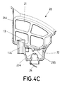
- Non-return flaps 13 (one of which is schematically illustrated in figure 4C ) can be provided in correspondence with the inlets 11 A.
- the second chamber 22 is situated below the first chamber 21, and accessible through an opening 21 B in the bottom of the first chamber.
- An outlet is provided at the bottom of the second chamber, covered by a filtering wall 22A of the second chamber, and optionally provided with a non-return device or flap 24.
- no non-return device is provided at the opening 21 B between the first chamber and the second chamber.
- the pump 3 pumps water from the water inlets 11, through inlets 11 A, and into the first chamber 21, through the filtering walls 21 A and out through an outlet (not shown) in the cover of the housing.
- the pump enters into a reverse mode, driving water from the outlet in the housing and through the filtering walls 21 A into the first chamber 21, reducing the clogging of said filtering walls.
- anti-return flaps 13 prevent the water from leaving the first chamber 21 through the inlets 11 A, thereby forcing the water to follow another path, namely, through opening 21 B, so that the water enters the second chamber 22, whereby debris is moved from the first chamber 21 into the second chamber 22.
- the water exits through the filtering wall 22A, while debris is retained in the second chamber 22.
- the filtering wall 22A is formed as a projection rising above the floor of the second chamber, so as to prevent the filtering wall 22A from becoming clogged when debris starts to accumulate.
- the non-return device 24 prevents water from entering the second chamber from outside the pool cleaner, when the pool cleaner is operating in the first operation mode.
- the user can remove the entire filter system 20, for example, opening a cover and lifting the filter system out of the pool cleaner. In other embodiments of the invention, only part of the filter system is removed for cleaning.
- a dirt detector 6 can be provided.
- the dirt detector can be a turbidity detector, as indicated in figure 5A , comprising a light source 64A (such as a LED), and a light sensor 65A arranged for receiving light scattered by dirt particles.
- a control device 63 is arranged for controlling the operation of the light source and for monitoring the output from the light detector, and the pool cleaner can be arranged to operate according to one of a plurality of available cleaning programs, depending on the output from the light sensor 65A. If the water is clean, only a small amount of light will be reflected so as to arrive at the light sensor. Thus, a high level of the output from the light sensor is indicative of dirt.
- the dirt detection is based on transmitted light, that is, the light source 64B is arranged to direct light towards the light sensor 65B, and a low level of the output from the light sensor may then be indicative of dirt.
- Figure 6 schematically illustrates how a pool cleaner in accordance with this embodiment of the invention may operate, in response to the output from the light sensor of a dirt detector.
- the pool cleaner is programmed with two different cleaning programs, a first one of which has been selected or designed for the treatment of less dirty areas of the swimming pool, and a second one of which has been selected or designed for the treatment of more dirty areas of the swimming pool.
- the second program may include operating the motors of the pool cleaner for driving back and forth or following a special scanning pattern, different from the one used in the first program, and/or operating the motors of the pool cleaner for driving the pool cleaner at a speed different from the one at which it is driven in accordance with the first program.
- the pool cleaner may initiate its operation in the first cleaning program, and while operating in accordance with said first cleaning program, the light source 64A/64B generates light and an output from the light sensor is monitored. If the output signal S is below a first threshold T1, the pool cleaner continues to operate in accordance with the first cleaning program. If the output from the light sensor rises above said first threshold T1, the pool cleaner switches to the second cleaning program (differing from the first cleaning program in terms of, for example, the speed with which the pool cleaner is made to move, and/or the scanning pattern that the pool cleaner is made to follow), where it remains until the output from the light sensor falls below a second threshold T2. In order to prevent frequent switching between cleaning programs, hysteresis can be provided so that T2 is sufficiently lower than T1.
- the filters comprise two distinct chambers separated by an opening.
- the filter may comprise three or more chambers.
- the filter comprises one chamber having two parts and a configuration that provides, in combination with the arrangement of the pump, that in the first operation mode debris is brought from the water inlet to a first part of the chamber (such as an upper part of the chamber, such as a part of the chamber placed near a water outlet where water leaves the cleaner in the first operation mode), and in the second operation mode, debris is brought from said first part of the chamber to a second part of the chamber (such as a lower part of the chamber and/or a part of the chamber placed towards the front, rear and/or a side of the swimming pool cleaner), the design of the filter being such that once the debris is in the second part of the chamber, the water flow in the first operation mode will not substantially carry said debris back to said first part.
- the use of at least two chambers may often be preferred due to simplicity of design and reliability
- the use of one chamber with a first and a second part as described can also be appropriate and may involve advantages, for example, in terms of simplicity when it comes to cleaning the entire filter.
- the first part may be placed above the second part, and/or the first part and the second part are placed differently in a longitudinal or transversal direction.
Abstract
Description
- The present invention relates to swimming pool cleaners.
- Swimming pools require cleaning, often on a daily basis. It is known in the art to use swimming pool cleaners that include some kind of drive system for displacing the swimming pool cleaner throughout the swimming pool, for example, by moving over the bottom surface of the swimming pool and, in the case of some types of swimming pool cleaners, also on the side walls of the swimming pool, and/or floating in the water of the swimming pool. Some swimming pool cleaners include drive means based on some kind of pump device that produces a water jet for displacing the swimming pool cleaner; for example, the water jet can be provided by an on-board pump driven by an electric motor, or by external pressure provided by the pool circulation pump or an independent pump. Other swimming pool cleaners include one or more motors for actuating drive devices such as wheels for driving the swimming pool cleaner so as to displace it over a surface; for example, the motor or motors can be electric or hydraulic, for example, driven by a water turbine with pressure being provided by an external pump.
- Swimming pool cleaners generally include, internally or externally, at least one pump device arranged to pump or suck water into the swimming pool cleaner through at least one water inlet and to expel water through at least one water outlet, filtering means being arranged between the inlet and the outlet so as to retain debris, such as dirt particles, leaves, etc.
- Swimming pool cleaners should be as efficient as possible in terms of power consumption and in terms of cleaning capacity, and they should also be as user-friendly as possible, requiring a minimum of maintenance and allowing for maintenance to be performed under user-friendly conditions.
- Here, one problem is that when, during use, the debris that enters through the water inlet is retained in the filter, the filter tends to get clogged. This also reduces the efficiency of the pump, as the debris restricts the flow. Thus, cleaning of the filter becomes necessary.
-
US-2004/0007522-A1 teaches a disposable pool cleaner filter which does not require cleaning but which can simply be thrown away and replaced after a cleaning cycle.US-6013178-A teaches a cartridge type filter which is simple to remove and replace. However, both filters are easily clogged during operation, for example, before the pool cleaner has scanned the entire surface of the swimming pool. -
WO-2007/015251-A2 describes a system for facilitating the cleaning of the filters of a swimming pool cleaner, by spraying water on the relatively rigid filter screens from outside, whereby debris and water exits through a cleaning outlet. -
US-3676884-A describes a swimming pool cleaner in which a strainer with a lid can be accessed from above and removed from the pool cleaner for cleaning. Other examples of filters that can be removed from above when the swimming pool cleaner is resting on a horizontal surface in its intended position of use are described inEP-1916359-A2 ,EP-2235292-B1 andEP-2235297-B1 . The pool cleaners described in these documents are intended to make it easy for the user to remove the filter for the purpose of cleaning it. - However, even though modern pool cleaner designs have converted the cleaning of the filters to a rather simple task, frequent cleaning of the filters is still annoying and costly as it requires interruption of the cleaning process, access to the pool cleaner (which in many cases is positioned on the floor of the swimming pool when the filter gets clogged) and intervention by an operator. To reduce the frequency with which the cleaning of filters has to be carried out, it is often desired to provide filters with a substantial volume, so that a substantial amount of debris can be accumulated before cleaning of the filter becomes necessary. However, even if the filter provides for space enough to house substantial amounts of debris, a problem that remains is that during operation, when debris starts to accumulate, it tends to clog the filter, thus reducing the hydraulic performance of the device. Many pool cleaners are designed to respond to a substantial reduction of the hydraulic performance by stopping operation of the motor, for example, in response to a detection of an increase in the current consumption. This means that when the filter starts to become clogged, the pool cleaner may stop in the middle of a cycle of the cleaning program. Also, with a lot of debris accumulated within the filter, the risk increases that debris may affect the operation of the non-return valve at the inlet and the risk that dirt may return to the swimming pool when the robot is removed.
-
US-2011/0162683 discloses a swimming pool cleaner comprising a filtration chamber provided in a hollow body, and a pumping device which creates a liquid flux in a normal cleaning direction, between at least one liquid inlet at the base of the hollow body and at least one main outlet through a filtering device. The pumping device is arranged so as to be able to produce a flow of liquid which is discharged via at least one secondary outlet, which is configured to orientate a current of liquid which is discharged via this secondary outlet and creates reaction forces generating a pivot torque of the hollow body. The pumping device is configured so as to be able to produce a flow of liquid, called a nosing-up flow, which flows in a backward direction from each main outlet and which is discharged via at least one secondary outlet which is configured to orientate the liquid current, called a nosing-up current, so that this nosing-up current creates reaction forces whose resultant generates a nosing-up torque and produces a nosing-up action of the apparatus by the hollow body being pivoted. The nosing-up flow is obtained by means of a flow which flows in a backward direction relative to the normal cleaning direction of the flow of liquid. In order to obtain said nosing-up flow, it is sufficient to reverse the operating direction of the pumping device. - Pool cleaners generally operate according to pre-established and fixed programs, for example, scanning the floor of the swimming pool according to a pre-set program or arbitrarily. As the floors of swimming pools generally have a fairly constant structure and similar characteristics all throughout the swimming pool, this has traditionally been considered appropriate and practical. Thus, and in contrast with other objects to be cleaned, such as in the case of autonomous floor cleaners (as disclosed in, for example,
US-2005/0166355-A1 andUS-5613261-A ), where the operation of the device is adapted according to dust or dirt present in the area being cleaned, for swimming pools it has traditionally been considered sufficient to operate according to a fixed program.EP-1540612-B1 teaches a swimming pool cleaner provided with an on-board sensor, but the sensor is not used for optimizing the operation of the swimming pool cleaner but just to collect data regarding characteristics and conditions of the water in the pool. - However, it has been found that it may often be the case that in spite of the generally homogeneous character of the floor of a swimming pool, some areas of a swimming pool may actually be substantially more dirty than other areas. This means that with known swimming pool cleaners, too much time may be spent on cleaning less dirty areas, and/or insufficient time may be spent on cleaning more dirty areas. It has been found that known swimming pool cleaners may not be fully efficient in what regards, for example, time and energy consumption. It is also considered that there is a risk that one or more areas of the swimming pool be left dirtier than desired after completion of a cleaning cycle.
-
US-2013/0152970-A1 discloses how the energy consumption of a swimming pool cleaner can be reduced by adapting the operation of a pump in response to the detection of a foreign object, but it has been found that further enhancement of efficiency is desirable. -
WO-2014/004929-A2 discloses a sophisticated pool cleaner with a laser range finder. The system can include a controller, a laser range finder including a first laser, a second laser, and a camera. The control system can be located on or in the pool cleaner and can optimize operation of the pool cleaner by mapping a swimming pool or spa environment and accurately positioning the pool cleaner throughout the environment. The control system can allegedly optimize cleaning routes and identify specific locations of debris within the environment. The controller can operate and receive inputs from the laser range finder and/or a second sensor assembly, and can operate a directional control mechanism to move the pool cleaner along a desired route within the underwater environment based on these inputs. The control system can allegedly determine and optimize cleaning routes and operate the pool cleaner to follow these optimized cleaning routes. The system involves the projection of two laser lines on an object, the capturing of images of the projected lines, and the calculation of a distance to an object based on a calculated pixel distance. The system allows for mapping using simultaneous localization and mapping (SLAM) techniques. - The invention relates to a swimming pool cleaner comprising:
- a housing,
- drive means for displacing the swimming pool cleaner,
- at least one water inlet,
- at least one water outlet,
- at least one filter, and
- at least one pump.
- The drive means are arranged for displacing the swimming pool cleaner, such as on a floor of a swimming pool, or floating in the water of a swimming pool. Any kind of drive means is within the scope of the present invention, as long as it is suitable for displacing the swimming pool cleaner. For example, the drive means can include one or more electric motors and/or wheels, such as wheels driven by one or more electric motors. The drive means can include means for generating a water jet or similar to displace the swimming pool cleaner; the means for generating a water jet or similar can include an internal or external pump. In some embodiments of the invention, the drive means comprise hydraulically driven wheels, for example, wheels that are driven by an external pump. The invention is not limited to any specific kind or type of drive means; for example, also swimming pool cleaners without wheels, such as swimming pool cleaners arranged to float in the water of a swimming pool, are within the scope of the invention.
- The term "filter" is to be interpreted in a generic sense and encompasses any filter device, filter system or filter means, such as a filter having one single chamber or a filter having two or more chambers, interconnected in one way or another so as to allow for operation in accordance with the invention.
- The term pump has to be interpreted in a generic sense, as including any device suitable for displacing water.
- The water inlet, the water outlet, the filter and the pump are arranged so that, in a first operation mode of the swimming pool cleaner, said at least one pump displaces water from said water inlet to said water outlet through said filter, so that debris entering through the water inlet with the water is retained in said filter.
- In accordance with the invention, the filter comprises a first part and a second part (which in some embodiments of the invention can form an integral part of one and the same main body, or which in other embodiments of the invention can be separate from each other although connected, for example, through some kind of conduit, to allow debris to be displaced from said first part to said second part), the swimming pool cleaner being configured so that
in said first operation mode of the swimming pool cleaner, debris entering the filter is retained in said first part,
and in a second operation mode of the swimming pool cleaner, debris is displaced from said first part to said second part. - The term "part" has to be interpreted in a generic sense, and can encompass any area (for example, on one or more filter walls or parts thereof) or volume (for example, one or more chambers of a filter, or one or more sub-volumes within a chamber of a filter). In some embodiments of the invention, each part is a chamber, and the filter may comprise two or more chambers, housed within a single enclosure or in different enclosures that are connected to each other, for example, through some kind of conduit or via a free space within the body of the swimming pool cleaner. In some embodiments of the invention, the first part and the second part are both within a single chamber, for example, as sub-areas of the walls of the chamber or as sub-volumes within the chamber.
- Thus, in the first operation mode, which can be the operation mode in which the swimming pool cleaner operates during the major portion of a cleaning cycle while scanning, for example, a floor and/or walls of a swimming pool, or when driven floating in the water of the swimming pool, water is pumped from the water inlet (or from some or all of the water inlets) to at least one water outlet, entering the filter and exiting through, for example, one or more filter walls thereof, whereby debris is retained by said filter walls, in said first part of the filter. In the second operation mode, which can be an operation mode into which the swimming pool cleaner is set occasionally, for example, at more or less regularly intervals during its operation, some, most, or at least part of the debris that has accumulated in said first part is displaced to said second part of the filter. By removing debris from the first part, it is possible to clear the path along which the water flows during normal operation of the device in the first operation mode, unclogging the part of the filter through which water flows when the pool cleaner is in the first operation mode, thereby enhancing the hydraulic efficiency of the pool cleaner during said first operation mode. This makes it possible to increase the time between cleaning of the filter by the user, and to reduce the risk of the pool cleaner stopping due to clogging during a cycle of the cleaning program. In many embodiments of the invention, the pool cleaner is designed so that substantially no debris, or as little debris as possible, be displaced from said second part to said first part when the pool cleaner returns to the first operation mode. At least, it is preferred to use a design and arrangement that prevents debris from being displaced form the second part to the first part when the pool cleaner is operating in the first operation mode.
- In some embodiments of the invention, the swimming pool cleaner is arranged, such as programmed, so that said at least one pump operates differently in said first operation mode than in said second operation mode. For example, the swimming pool cleaner can be arranged, such as programmed, so that said at least one pump drives water in a first direction in said first operation mode, and in a second direction substantially opposite to said first direction in said second operation mode. That is, changing from the first operation mode to the second operation mode can be carried out in a simple way, for example, electronically, by simply setting the pump into a reverse mode, and vice-versa. Thus, when the pump is operating in the normal or forward mode, water is made to flow so as to accumulate the debris in the first part of the filter, and upon reversal of the operation of the pump, water is driven in a different direction or flow pattern, so as to displace at least part of the debris from said first part of the filter to the second part of the filter.
- In some embodiments of the invention, the swimming pool cleaner comprises at least an additional pump, the additional pump being arranged to operate in the second operation mode but not in the first operation mode. That is, for example, a first pump can be used to pump debris into the first part of the filter during the first operation mode, and the second pump can be used to pump debris from the first part of the filter into the second part of the filter, when the pool cleaner is operating in the second operation mode.
- In some embodiments of the invention, the first part of the filter comprises (such as is, or constitutes, in accordance with different embodiments of the invention) a first chamber, and said second part of the filter comprises (such as is, or constitutes, in accordance with different embodiments of the invention) a second chamber.
- In some embodiments of the invention,
- said second chamber has a water outlet, a non-return device being placed in correspondence with said water outlet to prevent water from entering into said second chamber through said water outlet of the second chamber when the swimming pool cleaner is operating in the first operation mode (that is, to prevent, for example, that the water flow in the first operation mode sucks water into the second chamber, as this might drag debris back towards the first chamber),
and/or - said second chamber is separated from said first chamber by at least one non-return device (such as one or more flaps that can open towards the second chamber when the pressure is higher at the side facing the first chamber than at the other side, and that can close the flow path between the first and the second chamber when the pressure is not higher at the first chamber side; for example, the first and the second chamber can be separated from each other by a partition wall, and the non-return device can be placed in correspondence with the partition wall), so that debris can be displaced from said first chamber to said second chamber when the swimming pool cleaner is operating in the second operation mode, and so that debris cannot return from said second chamber to said first chamber when the swimming pool cleaner is operating in the first operation mode; that is, the two chambers can be separated from each other, for example, by some kind of partition wall or other means, and the one-way valve is provided to allow debris to travel in one direction and to prevent it from travelling in the opposite direction.
- In some embodiments of the invention, the first chamber and the second chamber are arranged separated from each other, and connected to each other by at least one conduit. This arrangement increases the design options, as the two chambers can be placed separated from each other, thereby increasing the number of possibilities according to which the filter can be distributed within the housing of the pool cleaner. In some embodiments, a non-return device can be provided in correspondence with said conduit to allow debris to pass from the first chamber to the second chamber through said conduit, and to prevent debris from passing from said second chamber to said first chamber. In some embodiments of the invention, a non-return device can be placed in correspondence with an outlet from the second chamber.
- In some embodiments of the invention, a non-return device is provided to prevent debris from being driven out of the water inlet when the swimming pool cleaner is operating in the second operation mode. This non-return device can be placed at the inlet or away from the inlet but prior to the first chamber or the first part of the filter, in the direction of flow from the inlet towards the first part of the filter. It can also be placed in the first chamber.
- In some embodiments of the invention, said second part of the filter is arranged so that it can be separated from the first part of the filter. Thus, one part of the filter can be removed without removing the other part, which can make it more easy to remove and clean the second part of the filter, and to design a filter allowing for a user-friendly removal and cleaning of the second part of the filter.
- In some embodiments of the invention, said second part of the filter is arranged outside the housing, so that it can be viewed and accessed, for example, for removal and cleaning, without opening the housing. This can be advantageous to facilitate maintenance and to avoid any unnecessary opening of the housing. In some embodiments of the invention, a user can monitor the second part of the filter, such as a second chamber as described above, from above, while the robot is operating in the swimming pool, for example, floating in the swimming pool or operating on the floor of the swimming pool, so as to check whether there is enough debris to justify cleaning/removal of the second part.
- In some embodiments of the invention, said second part of the filter is arranged within the housing and arranged so that said second part of the filter can be removed through an opening in the housing, such as an opening in a top or side portion of the housing, without removing said first part of the filter from the housing. That is, when with time the second part of the filter is filled with debris that has been removed from the first part of the filter during operation of the swimming pool cleaner, the second part of the filter can be removed, optionally together with the corresponding non-return device when such a device is provided, for cleaning and removal of debris, whereas the first part of the filter, comparatively clean due to the backwash effect of the second operation mode, can remain within the pool cleaner. This provides for increased flexibility in the design of the pool cleaner, as the second part of the filter, which generally will have to be cleaned more frequently, can be arranged in a position so that it is easy to remove it, whereas the first part of the filter, which may require maintenance less frequently, can be provided in a position that does not necessarily have to allow for an equally simple removal. Thus, this solution can increase the flexibility in terms of design of specific pool cleaner layouts, and provide for a balance between user-friendliness in terms of cleaning and maintenance, and design and compactness of the device.
- In some embodiments of the invention, the swimming pool cleaner is arranged to switch from said first operation mode to said second operation mode in response to an accumulation of debris in said first part of the filter system. For example, in some embodiments of the invention, the swimming pool cleaner comprises at least one detector responsive to accumulation of debris in said first part of the filter device, for example, an optical detector receiving light from a light source whereby the received signal is influenced by the accumulation of debris in said first part, for example, on a portion of a filter wall or within a filter chamber, or a detector responsive to a variation in the water flow that may be caused by accumulation of debris. In other embodiments of the invention, the switching from the first operation mode to the second operation mode takes place in response to a variation in power or current consumption of the pump, due to partial blocking of a flow path.
- In some embodiments of the invention, the swimming pool cleaner is arranged to switch from said first operation mode to said second operation mode after having operated in said first operation mode for a predetermined amount of time. That is, switching between the first and second operation modes can take place regularly, at intervals that, for example, can be programmed by a user.
- In some embodiments of the invention, the swimming pool cleaner further comprises a dirt detector, the swimming pool cleaner being arranged to selectively operate according to one of a plurality of available cleaning programs, selected as a function of an output from said dirt detector. Also this helps to enhance efficiency of the pool cleaner. It has been found that sometimes, in swimming pools, dirt may be concentrated in one or more areas, or at least distributed so that there is more dirt in some areas than in other areas. Thus, a swimming pool cleaner operating in the same way throughout the swimming pool may not clean some areas sufficiently, or may spend too much time and/or power on cleaning the less dirty areas, thereby operating with sub-optimal efficiency. Thus, and whereas traditional swimming pool cleaners can produce acceptable results in terms of cleaning if they are allowed to operate for a sufficiently long time, by using a dirt detector, the swimming pool cleaner can adapt the way in which it operates in accordance with the level of dirt that is detected, for example, in terms of turbidity. Turbidity sensors are well known in the art of washing machines or dishwashers, and many commercially available ones can be readily applied to pool cleaners. Thus, the swimming pool cleaner can be configured to operate in accordance with one of a plurality of available cleaning programs, such as two or more different cleaning programs, the cleaning program being selected based on the output from the dirt detector. Thus, for example, the pool cleaner can spend more time in the dirtier areas of the swimming pool than in the less dirty areas of the swimming pool. The cleaning programs can differ from each other in terms of, for example, the speed (driving speed) with which the swimming pool cleaner is made to move in the swimming pool, such as over the floor of the swimming pool or floating in the water of the swimming pool, and/or the pattern which the swimming pool cleaner follows when moving in the swimming pool. The dirt sensor can even be used to determine when the swimming pool cleaner is to be set in a backwash mode. In many embodiments of the invention, the dirt sensor is arranged in correspondence with a water inlet, for example, within a body or housing of the swimming pool cleaner, for example, close to a water inlet, so as to be responsive to the amount or concentration of dirt in the water that is entering into the filter. Thus, the dirt sensor can be housed safely within the body or housing of a swimming pool cleaner, while being able to reliably detect dirt entering with the water flow.
- In some embodiments of the invention, at least one of said available cleaning programs is arranged for driving the swimming pool cleaner, via said drive means, with a first speed, and at least another one of said available cleaning programs is arranged for driving the swimming pool cleaner, via said drive means, with a second speed, different from said first speed.
- In some embodiments of the invention, at least one of said available cleaning programs is arranged for driving the swimming pool cleaner in accordance with a first scanning pattern and wherein at least another one of said available cleaning programs is arranged for driving the swimming pool cleaner in accordance with a second scanning pattern, different from said first scanning pattern.
- That is, the swimming pool cleaner can be configured to operate in accordance with one of a plurality of available cleaning programs, such as two or more different cleaning programs, the cleaning program being selected based on the output from the dirt detector. Thus, for example, the pool cleaner can spend more time in the dirtier areas of the swimming pool than in the less dirty areas of the swimming pool. The cleaning programs can differ from each other in terms of, for example, the driving speed with which the swimming pool cleaner is made to move (for example, over the floor of the swimming pool or floating in the water of the swimming pool, using the drive means), and/or the pattern which the swimming pool cleaner follows when moving in the swimming pool, that is, the scanning pattern.
- To complete the description and in order to provide for a better understanding of the invention, a set of drawings is provided. Said drawings form an integral part of the description and illustrate embodiments of the invention, which should not be interpreted as restricting the scope of the invention, but just as examples of how the invention can be carried out. The drawings comprise the following figures:
-
Figures 1A-1C schematically illustrate the operation of a swimming pool cleaner according to a first embodiment of the invention. -
Figure 2 schematically illustrates a swimming pool cleaner according to another embodiment of the invention. -
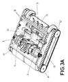
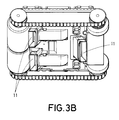
Figures 3A and3B are perspective views from above and below, respectively, of part of a swimming pool cleaner according to an embodiment of the invention. -
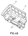
Figures 4A-4C are two perspective views and one cross sectional view of a filter system that can be used in the swimming pool cleaner offigures 3A and3B . -
Figures 5A and 5B schematically illustrate dirt detectors in accordance with two possible embodiments of the invention. -
Figure 6 illustrates how a swimming pool cleaner with a dirt detector can operate, according to an embodiment of the invention. - As shown in
figure 1A , a swimming pool cleaner in accordance with an embodiment of the invention comprises ahousing 1 with a removable or pivotably arrangedcover 2, awater inlet 11 and afirst water outlet 12, with anon-return device 13 being arranged in correspondence with said water inlet. Also asecond water outlet 14 is provided. - Inside the housing there is a motor (not shown) for driving the swimming pool cleaner or robot over the floor of the swimming pool, and a pump (not shown), as well as a
filter 20 comprising afirst chamber 21 and asecond chamber 22, separated by apartition wall 23 in which an opening is provided which allows water to flow from thefirst chamber 21 to thesecond chamber 22. Thesecond chamber 22 is in fluid connection with thesecond water outlet 14 through afilter wall 22A which extends into thesecond chamber 22, upwards from the floor of thesecond chamber 22, so as to make sure that it will not be clogged by debris deposited on the floor of the second chamber. Anon-return device 24 is provided at thesecond water outlet 14, to prevent water from entering when the pool cleaner is operating in the first operation mode. - The
first chamber 21 haslateral filtering walls 21 A. Thefilter 20 can be removed by opening thecover 2 and lifting theentire filter 20 out of thehousing 1. -
Figure 1B shows how water flows when the pool cleaner is in a first operation mode, in which the pump is driving water from thewater inlet 11 to thefirst water outlet 12. Here, the water is pumped through thefirst chamber 21 of thefilter 20, and filtered through thefiltering walls 21 A, so that debris is retained in this first part of the filter, that is, in saidfirst chamber 21. The water that exits through saidfiltering walls 21A leaves the housing of the pool cleaner through saidfirst water outlet 12. - With time, debris starts to accumulate inside the
first chamber 21 and, due to the movement of the water, also on thefiltering walls 21 A, which tend to get clogged. Thus, to prevent reduction of the hydraulic efficiency, the swimming pool cleaner can be set into a second operation mode, namely, a backwash mode, for example, by reversing operation of the pump, or by stopping operation of the pump and instead activating another pump. In the backwash mode, the water flows as illustrated infigure 1C , that is, water enters through the first water outlet 12 (which can include some kind of filtering means to prevent debris from being sucked into the device), enters thefirst chamber 21 through thefiltering walls 21 A (thereby removing debris from them due to the backwash effect) and enters thesecond chamber 22, thereby carrying at least part of the debris from thefirst chamber 21 to thesecond chamber 22, where it is retained when the water exits through thefiltering wall 22A and thesecond water outlet 14. Next, the pool cleaner can return to the first operation mode, that is, the normal cleaning mode, illustrated infigure 1B . As at least part of the debris has been transferred from thefirst chamber 21 to thesecond chamber 22, this part of the debris will no longer be in the path along which water flows when pumped from thewater inlet 11 to thefirst water outlet 12, thereby enhancing the hydraulic performance. This increases efficiency and the time between manual cleaning by a user, and reduces the risk that the pool cleaner will stop operating during a cleaning cycle due to excessive clogging of the filter. Of course, now and then it will be necessary to remove the debris from the second chamber. In some embodiments of the invention, this can be done by opening thecover 2 and removing theentire filter 20, with the first and the second chambers, and proceed to cleaning them in a conventional manner. For example, thefilter 20 can be provided with one or more lids that can be opened to allow for debris to be removed. -
Figure 2 schematically illustrates a second embodiment of the invention. The swimming pool cleaner according to this embodiment includes awater inlet 11 and awater outlet 12, and a filter comprising afirst chamber 21 having afiltering wall 21 A and asecond chamber 22 having afiltering wall 22A. In some embodiments of the invention, thesecond chamber 22 is housed within the housing of the swimming pool cleaner. For example, the second chamber can be accessible through some kind of cover, for example, so as to be removable for cleaning. In some other embodiments of the invention, the second chamber is placed outside the housing of the swimming pool cleaner, for example, as an external accessory that can be connected to the body of swimming pool cleaner. This provides for simple removal and cleaning of the second chamber, and can make it easy for a user to observe, for example, from above and without taking the swimming pool cleaner out of the swimming pool, to what extent the second chamber has been filled with debris and may require cleaning. - The first and the second chambers of the filter are connected by means of a
conduit 25. When operating in a first operation mode, thepump 3 pumps water so that water enters through thewater inlet 11 and thenon-return device 13, into thefirst chamber 21, where the water passes through thefiltering wall 21 A and out through thewater outlet 12. Debris is retained by said filteringwall 21 A. With time, the accumulation of debris causes clogging of thefiltering wall 21 A and thus reduces the hydraulic efficiency. Therefore, to prevent or reduce the clogging, the swimming pool cleaner is set into the second operation mode, during which thepump 3 pumps water from theoutlet 12 into thefirst chamber 21 through saidfiltering wall 21 A, thereby reducing clogging. As thenon-return device 13 prevents the water from exiting the housing through thewater inlet 11, the water is pumped through theconduit 25, moving at least part of the debris contained in thefirst chamber 21 into thesecond chamber 22. Here, water exits thefiltering wall 22A which can be in communication with the outside of the pool cleaner or even be placed outside the housing of the pool cleaner. In this second embodiment, for manual cleaning, it can often be enough that the users removes thesecond chamber 22, as thefirst chamber 21, and especially itsfiltering wall 21 A, can often be sufficiently cleaned due to the backwash effect described above. - In both of the embodiments described above, the change between the first operation mode and the second operation mode can take place at predetermined intervals, or as a response to a detection of clogging, for example, as a response to an increase in the power consumption of the pump.
-
Figures 3A and3B illustrate an embodiment of the invention in whichwheels 41 are driven by two electrical motors 4, arranged on respective sides of apump 3 which is arranged to pump the water according to the principles described above, both in the first operation mode and in the second operation mode. The motors 4 and thepump 3 are arranged within a frame structure of the housing, with asubstantial space 5 being available for accommodating the filter. Although the illustrated embodiment includes electrical motors and wheels for displacing the swimming pool cleaner, any other kind of drive means is within the scope of the invention, including hydraulic drive means such as means for displacing the pool cleaner by means of a water jet or similar, and hydraulically driven wheels. Although the pool cleaner of the illustrated embodiment has wheels, also pool cleaners without wheels are within the scope of the invention. - Three
water inlets 11 are provided in the floor of the housing, arranged to be connected to the filter system. Also,second water outlets 14 corresponding to those offigures 1A-1C are provided. The inlets are also shown schematically infigure 3B ; they are placed in different positions both in the longitudinal and in the transversal direction, and can be provided with telescopic members arranged to be moveable in the vertical direction. Infigure 3A , adirt detector 6 is illustrated schematically. It is placed in correspondence with one of the water inlets, so as to allow for detection of dirt in the water that is entering the filter. -
Figures 4A-4C illustrate how thefilter 20 can compriseinlets 11 A arranged to be positioned in correspondence with thewater inlets 11 of the pool cleaner, so as to lead water from saidwater inlets 11 into afirst chamber 21 of the filter, which comprises filteringwalls 21 A and optionally a cover which may or may not be a filtering cover. Alternatively, thefirst chamber 21 can simply be closed from above by a pivotable or removable cover of the housing of the pool cleaner. Non-return flaps 13 (one of which is schematically illustrated infigure 4C ) can be provided in correspondence with theinlets 11 A. - In this embodiment of the invention, the
second chamber 22 is situated below thefirst chamber 21, and accessible through anopening 21 B in the bottom of the first chamber. An outlet is provided at the bottom of the second chamber, covered by afiltering wall 22A of the second chamber, and optionally provided with a non-return device orflap 24. In this embodiment of the invention, no non-return device is provided at theopening 21 B between the first chamber and the second chamber. - In the first operation mode, the
pump 3 pumps water from thewater inlets 11, throughinlets 11 A, and into thefirst chamber 21, through thefiltering walls 21 A and out through an outlet (not shown) in the cover of the housing. At certain intervals, for example, at predetermined intervals or responsive to a detection of clogging of thefiltering walls 21 A, the pump enters into a reverse mode, driving water from the outlet in the housing and through thefiltering walls 21 A into thefirst chamber 21, reducing the clogging of said filtering walls. Here,anti-return flaps 13 prevent the water from leaving thefirst chamber 21 through theinlets 11 A, thereby forcing the water to follow another path, namely, through opening 21 B, so that the water enters thesecond chamber 22, whereby debris is moved from thefirst chamber 21 into thesecond chamber 22. Here, the water exits through thefiltering wall 22A, while debris is retained in thesecond chamber 22. It can be observed how thefiltering wall 22A is formed as a projection rising above the floor of the second chamber, so as to prevent thefiltering wall 22A from becoming clogged when debris starts to accumulate. Thenon-return device 24 prevents water from entering the second chamber from outside the pool cleaner, when the pool cleaner is operating in the first operation mode. - When it becomes necessary to clean the filter manually, the user can remove the
entire filter system 20, for example, opening a cover and lifting the filter system out of the pool cleaner. In other embodiments of the invention, only part of the filter system is removed for cleaning. - As indicated above, a
dirt detector 6 can be provided. The dirt detector can be a turbidity detector, as indicated infigure 5A , comprising alight source 64A (such as a LED), and alight sensor 65A arranged for receiving light scattered by dirt particles. Acontrol device 63 is arranged for controlling the operation of the light source and for monitoring the output from the light detector, and the pool cleaner can be arranged to operate according to one of a plurality of available cleaning programs, depending on the output from thelight sensor 65A. If the water is clean, only a small amount of light will be reflected so as to arrive at the light sensor. Thus, a high level of the output from the light sensor is indicative of dirt. In other embodiments of the invention, such as in the one schematically illustrated infigure 5B , the dirt detection is based on transmitted light, that is, thelight source 64B is arranged to direct light towards thelight sensor 65B, and a low level of the output from the light sensor may then be indicative of dirt. -
Figure 6 schematically illustrates how a pool cleaner in accordance with this embodiment of the invention may operate, in response to the output from the light sensor of a dirt detector. The pool cleaner is programmed with two different cleaning programs, a first one of which has been selected or designed for the treatment of less dirty areas of the swimming pool, and a second one of which has been selected or designed for the treatment of more dirty areas of the swimming pool. For example, the second program may include operating the motors of the pool cleaner for driving back and forth or following a special scanning pattern, different from the one used in the first program, and/or operating the motors of the pool cleaner for driving the pool cleaner at a speed different from the one at which it is driven in accordance with the first program. The pool cleaner may initiate its operation in the first cleaning program, and while operating in accordance with said first cleaning program, thelight source 64A/64B generates light and an output from the light sensor is monitored. If the output signal S is below a first threshold T1, the pool cleaner continues to operate in accordance with the first cleaning program. If the output from the light sensor rises above said first threshold T1, the pool cleaner switches to the second cleaning program (differing from the first cleaning program in terms of, for example, the speed with which the pool cleaner is made to move, and/or the scanning pattern that the pool cleaner is made to follow), where it remains until the output from the light sensor falls below a second threshold T2. In order to prevent frequent switching between cleaning programs, hysteresis can be provided so that T2 is sufficiently lower than T1. - In the embodiments illustrated above, the filters comprise two distinct chambers separated by an opening. In other embodiments of the invention, the filter may comprise three or more chambers. In some embodiment of the invention, the filter comprises one chamber having two parts and a configuration that provides, in combination with the arrangement of the pump, that in the first operation mode debris is brought from the water inlet to a first part of the chamber (such as an upper part of the chamber, such as a part of the chamber placed near a water outlet where water leaves the cleaner in the first operation mode), and in the second operation mode, debris is brought from said first part of the chamber to a second part of the chamber (such as a lower part of the chamber and/or a part of the chamber placed towards the front, rear and/or a side of the swimming pool cleaner), the design of the filter being such that once the debris is in the second part of the chamber, the water flow in the first operation mode will not substantially carry said debris back to said first part. Whereas the use of at least two chambers may often be preferred due to simplicity of design and reliability, the use of one chamber with a first and a second part as described can also be appropriate and may involve advantages, for example, in terms of simplicity when it comes to cleaning the entire filter. In some embodiments of the invention, the first part may be placed above the second part, and/or the first part and the second part are placed differently in a longitudinal or transversal direction.
- In this text, the term "comprises" and its derivations (such as "comprising", etc.) should not be understood in an excluding sense, that is, these terms should not be interpreted as excluding the possibility that what is described and defined may include further elements, steps, etc.
- On the other hand, the invention is obviously not limited to the specific embodiment(s) described herein, but also encompasses any variations that may be considered by any person skilled in the art (for example, as regards the choice of materials, dimensions, components, configuration, etc.), within the general scope of the invention as defined in the claims.
Claims (14)
- A swimming pool cleaner comprising
a housing (1, 2),
drive means (4, 41) for displacing the swimming pool cleaner,
at least one water inlet (11),
at least one water outlet (12),
at least one filter (20), and
at least one pump (3);
said water inlet (11), water outlet (12), filter (20) and pump (3) being arranged so that, in a first operation mode of the swimming pool cleaner, said at least one pump (3) displaces water from said water inlet (11) to said water outlet (12) through said filter (20), so that debris entering through the water inlet (11) with the water is retained in said filter (20);
characterized in that
the filter (20) comprises a first part and a second part, the swimming pool cleaner being configured so that
in said first operation mode of the swimming pool cleaner, debris entering the filter (20) is retained in said first part,
and in a second operation mode of the swimming pool cleaner, debris is displaced from said first part to said second part. - The swimming pool cleaner according to claim 1, arranged so that said at least one pump (3) operates differently in said first operation mode than in said second operation mode.
- The swimming pool cleaner according to claim 2, arranged so that said at least one pump (3) drives water in a first direction in said first operation mode, and in a second direction substantially opposite to said first direction in said second operation mode.
- The swimming pool cleaner according to claim 1, comprising at least an additional pump, the additional pump being arranged to operate in the second operation mode but not in the first operation mode.
- The swimming pool cleaner according to any of the preceding claims, wherein said first part of the filter comprises a first chamber (21), and wherein said second part of the filter comprises a second chamber (22).
- The swimming pool cleaner according to claim 5, wherein- said second chamber has a water outlet (14), a non-return device (24) being placed in correspondence with said water outlet (14) to prevent water from entering into said second chamber (22) through said water outlet (14) of the second chamber when the swimming pool cleaner is operating in the first operation mode;
and/or- said second chamber (22) is separated from said first chamber (21) by at least one non-return device, so that debris can be displaced from said first chamber (21) to said second chamber (22) when the swimming pool cleaner is operating in the second operation mode, and so that debris cannot return from said second chamber (22) to said first chamber (21) when the swimming pool cleaner is operating in the first operation mode. - The swimming pool cleaner according to claim 5, wherein the first chamber (21) and the second chamber (22) are arranged separated from each other, and connected to each other by at least one conduit (25).
- The swimming pool cleaner according to any of the preceding claims, wherein said second part of the filter is arranged so that it can be separated from the first part of the filter.
- The swimming pool cleaner according to claim 8, wherein said second part of the filter is arranged outside the housing (1, 2).
- The swimming pool cleaner according to claim 8, wherein said second part of the filter is arranged within the housing (1, 2) and arranged so that said second part of the filter can be removed through an opening in the housing without removing said first part of the filter from the housing.
- The swimming pool cleaner according to any of the preceding claims,- wherein the swimming pool cleaner is arranged to switch from said first operation mode to said second operation mode in response to an accumulation of debris in said first part of the filter system,- or wherein the swimming pool cleaner is arranged to switch from said first operation mode to said second operation mode after having operated in said first operation mode for a predetermined amount of time.
- The swimming pool cleaner according to any of the preceding claims, further comprising a dirt detector (6), the swimming pool cleaner being arranged to selectively operate according to one of a plurality of available cleaning programs, selected as a function of an output from said dirt detector.
- The swimming pool cleaner according to claim 12, wherein at least one of said available cleaning programs is arranged for driving the swimming pool cleaner, via said drive means (4, 41), with a first speed, and wherein at least another one of said available cleaning programs is arranged for driving the swimming pool cleaner, via said drive means (4, 41), with a second speed, different from said first speed.
- The swimming pool cleaner according to claim 12 or 13, wherein at least one of said available cleaning programs is arranged for driving the swimming pool cleaner in accordance with a first scanning pattern and wherein at least another one of said available cleaning programs is arranged for driving the swimming pool cleaner in accordance with a second scanning pattern, different from said first scanning pattern.
Priority Applications (1)
| Application Number | Priority Date | Filing Date | Title |
|---|---|---|---|
| EP14191948.0A EP2821564B1 (en) | 2014-01-07 | 2014-11-05 | Swimming pool cleaner |
Applications Claiming Priority (2)
| Application Number | Priority Date | Filing Date | Title |
|---|---|---|---|
| EP14150366 | 2014-01-07 | ||
| EP14191948.0A EP2821564B1 (en) | 2014-01-07 | 2014-11-05 | Swimming pool cleaner |
Publications (3)
| Publication Number | Publication Date |
|---|---|
| EP2821564A2 true EP2821564A2 (en) | 2015-01-07 |
| EP2821564A3 EP2821564A3 (en) | 2015-02-25 |
| EP2821564B1 EP2821564B1 (en) | 2016-04-13 |
Family
ID=49885163
Family Applications (2)
| Application Number | Title | Priority Date | Filing Date |
|---|---|---|---|
| EP14191969.6A Active EP2835478B1 (en) | 2014-01-07 | 2014-11-05 | Swimming pool cleaner |
| EP14191948.0A Active EP2821564B1 (en) | 2014-01-07 | 2014-11-05 | Swimming pool cleaner |
Family Applications Before (1)
| Application Number | Title | Priority Date | Filing Date |
|---|---|---|---|
| EP14191969.6A Active EP2835478B1 (en) | 2014-01-07 | 2014-11-05 | Swimming pool cleaner |
Country Status (3)
| Country | Link |
|---|---|
| US (3) | US9506262B2 (en) |
| EP (2) | EP2835478B1 (en) |
| AU (2) | AU2014274646B2 (en) |
Cited By (5)
| Publication number | Priority date | Publication date | Assignee | Title |
|---|---|---|---|---|
| WO2016137886A1 (en) * | 2015-02-24 | 2016-09-01 | Hayward Industries, Inc. | Pool cleaner with optical out-of-water and debris detection |
| EP3205793A1 (en) * | 2016-02-11 | 2017-08-16 | Maytronics Ltd. | Self cleaning pool cleaner |
| WO2019213002A1 (en) * | 2018-05-04 | 2019-11-07 | Zodiac Pool Care Europe | Swimming pool cleaner with illuminated debris filter |
| EP3712358A1 (en) * | 2019-03-22 | 2020-09-23 | Kokido Development Limited | Autonomous robot with alternating suction for cleaning swimming pools |
| EP4116522A1 (en) * | 2021-07-06 | 2023-01-11 | Maytronics Ltd. | Pool cleaning robot backwash system and method |
Families Citing this family (21)
| Publication number | Priority date | Publication date | Assignee | Title |
|---|---|---|---|---|
| US20170057759A1 (en) * | 2013-10-13 | 2017-03-02 | Maytronics Ltd. | Pool cleaning robot and a method for extracting the pool cleaning robot from a pool |
| FR3035906B1 (en) | 2015-05-07 | 2020-03-27 | Zodiac Pool Care Europe | OPTIMIZED SWIMMING POOL CLEANER |
| US10844621B2 (en) | 2016-12-08 | 2020-11-24 | Zodiac Pool Systems Llc | Enhanced filter door |
| US10550594B2 (en) | 2017-04-20 | 2020-02-04 | International Business Machines Corporation | Automated cleaning device |
| US10214933B2 (en) | 2017-05-11 | 2019-02-26 | Hayward Industries, Inc. | Pool cleaner power supply |
| US10364905B2 (en) | 2017-05-11 | 2019-07-30 | Hayward Industries, Inc. | Pool cleaner check valve |
| USD866102S1 (en) * | 2017-06-01 | 2019-11-05 | Maytronics Ltd. | Pool cleaner |
| USD874756S1 (en) * | 2017-06-01 | 2020-02-04 | Maytronics Ltd. | Pool cleaner with rear thrusters |
| USD874755S1 (en) * | 2017-06-01 | 2020-02-04 | Maytronics Ltd. | Pool cleaner with rear thrusters |
| ES2895364T3 (en) | 2017-07-27 | 2022-02-21 | Zodiac Pool Care Europe | Automatic pool cleaners with filter load indicators |
| WO2019135908A1 (en) | 2018-01-04 | 2019-07-11 | Zodiac Pool Systems Llc | Automatic swimming pool cleaners |
| USD859765S1 (en) * | 2018-03-23 | 2019-09-10 | Compurobot Technology Company | Pool cleaner |
| USD876733S1 (en) * | 2018-03-23 | 2020-02-25 | Compurobot Technology Company | Water jet propulsion pool cleaner |
| USD858917S1 (en) * | 2018-03-23 | 2019-09-03 | Compurobot Technology Company | Pool cleaner |
| USD849343S1 (en) * | 2018-03-23 | 2019-05-21 | Compurobot Technology Company | Pool cleaner |
| USD849342S1 (en) * | 2018-03-23 | 2019-05-21 | Compurobot Technology Company | Pool cleaner |
| AU2019322204B2 (en) * | 2018-08-14 | 2022-12-01 | Zodiac Pool Care Europe | Autonomous cleaning systems principally for swimming pools |
| US11304581B2 (en) | 2019-01-08 | 2022-04-19 | Bissell Inc. | Surface cleaning apparatus |
| US10774557B1 (en) | 2019-02-21 | 2020-09-15 | Aquatron Robotic Technology Ltd. | Pool cleaner with selective inlet control |
| AU2020260510B2 (en) * | 2019-11-06 | 2022-03-31 | Bissell Inc. | Surface cleaning apparatus |
| CN115234051B (en) * | 2022-08-25 | 2024-03-26 | 深圳市思傲拓科技有限公司 | Swimming pool cleaning robot and control method |
Citations (13)
| Publication number | Priority date | Publication date | Assignee | Title |
|---|---|---|---|---|
| US3676884A (en) | 1970-04-14 | 1972-07-18 | Stanley S Wulc | Random motion suction cleaner |
| US5613261A (en) | 1994-04-14 | 1997-03-25 | Minolta Co., Ltd. | Cleaner |
| US6013178A (en) | 1998-10-15 | 2000-01-11 | Aqua-Vac Systems, Inc. | Water filter and water filter assembly for robotic underwater swimming pool cleaning machines |
| US20040007522A1 (en) | 2002-07-03 | 2004-01-15 | Maytronics Ltd. | Liquid filter element |
| US20050166355A1 (en) | 2004-01-30 | 2005-08-04 | Funai Electric Co., Ltd. | Autonomous mobile robot cleaner |
| WO2007015251A2 (en) | 2005-08-04 | 2007-02-08 | Maytronics Ltd. | Pool cleaning robot |
| EP1916359A2 (en) | 2006-10-26 | 2008-04-30 | Aquatron Robotic Systems Ltd. | Swimming pool robot |
| EP1540612B1 (en) | 2002-08-23 | 2009-12-02 | Aqua Products Inc. | Pool cleaner with on-board water analysis, data recording and transmission device |
| US20110162683A1 (en) | 2009-12-18 | 2011-07-07 | Emmanuel Mastio | Apparatus for cleaning an immersed surface having a hydraulic nosing-up action |
| EP2235292B1 (en) | 2007-12-21 | 2011-08-31 | Zodiac Pool Care Europe | Apparatus for cleaning a submerged surface with removable filtration device |
| EP2235297B1 (en) | 2007-12-21 | 2011-08-31 | Zodiac Pool Care Europe SAS | Apparatus for cleaning a submerged surface with a disconnectable dirty circuit |
| US20130152970A1 (en) | 2011-12-19 | 2013-06-20 | Aquatron Robotic Technology Ltd. | Automatic pool cleaner for cleaning a pool with minimum power consumption and method thereof |
| WO2014004929A2 (en) | 2012-06-27 | 2014-01-03 | Pentair Water Pool And Spa, Inc. | Pool cleaner with laser range finder system and method |
Family Cites Families (7)
| Publication number | Priority date | Publication date | Assignee | Title |
|---|---|---|---|---|
| EP1370737A1 (en) * | 2001-02-28 | 2003-12-17 | Azoteq (PTY) Limited | Method of and apparatus for controlling the operation of a suction-type pool cleaner |
| FR2954380B1 (en) | 2009-12-18 | 2015-03-20 | Zodiac Pool Care Europe | IMMERGE SURFACE CLEANING APPARATUS WITH CABINAGE GIRATION |
| FR2954379B1 (en) | 2009-12-18 | 2012-04-13 | Zodiac Pool Care Europe | SUBMERSIBLE SURFACE CLEANING APPARATUS WITH AT LEAST ONE NON-MOTOR ROLLING MEMBER OFFSET LATERALLY |
| US9091093B2 (en) | 2012-07-10 | 2015-07-28 | Aqua Products, Inc. | Internal backwash system for robotic swimming pool cleaner |
| IL221876A (en) | 2012-09-11 | 2016-12-29 | Shlomi-Shlomi Idan | Filter for pool cleaning apparatus including backwash |
| ES2775002T3 (en) * | 2012-12-17 | 2020-07-23 | Spectralight Tech Inc | Pool cleaning robot |
| WO2014151267A1 (en) | 2013-03-15 | 2014-09-25 | Hayward Industries, Inc. | Swimming pool cleaner with docking system and/or other related systems and methods |
-
2014
- 2014-11-05 EP EP14191969.6A patent/EP2835478B1/en active Active
- 2014-11-05 EP EP14191948.0A patent/EP2821564B1/en active Active
- 2014-12-12 AU AU2014274646A patent/AU2014274646B2/en active Active
- 2014-12-12 AU AU2014274645A patent/AU2014274645B2/en active Active
-
2015
- 2015-01-06 US US14/590,486 patent/US9506262B2/en active Active
- 2015-01-06 US US14/590,381 patent/US9896856B2/en active Active
-
2018
- 2018-02-02 US US15/887,632 patent/US10087646B2/en active Active
Patent Citations (13)
| Publication number | Priority date | Publication date | Assignee | Title |
|---|---|---|---|---|
| US3676884A (en) | 1970-04-14 | 1972-07-18 | Stanley S Wulc | Random motion suction cleaner |
| US5613261A (en) | 1994-04-14 | 1997-03-25 | Minolta Co., Ltd. | Cleaner |
| US6013178A (en) | 1998-10-15 | 2000-01-11 | Aqua-Vac Systems, Inc. | Water filter and water filter assembly for robotic underwater swimming pool cleaning machines |
| US20040007522A1 (en) | 2002-07-03 | 2004-01-15 | Maytronics Ltd. | Liquid filter element |
| EP1540612B1 (en) | 2002-08-23 | 2009-12-02 | Aqua Products Inc. | Pool cleaner with on-board water analysis, data recording and transmission device |
| US20050166355A1 (en) | 2004-01-30 | 2005-08-04 | Funai Electric Co., Ltd. | Autonomous mobile robot cleaner |
| WO2007015251A2 (en) | 2005-08-04 | 2007-02-08 | Maytronics Ltd. | Pool cleaning robot |
| EP1916359A2 (en) | 2006-10-26 | 2008-04-30 | Aquatron Robotic Systems Ltd. | Swimming pool robot |
| EP2235292B1 (en) | 2007-12-21 | 2011-08-31 | Zodiac Pool Care Europe | Apparatus for cleaning a submerged surface with removable filtration device |
| EP2235297B1 (en) | 2007-12-21 | 2011-08-31 | Zodiac Pool Care Europe SAS | Apparatus for cleaning a submerged surface with a disconnectable dirty circuit |
| US20110162683A1 (en) | 2009-12-18 | 2011-07-07 | Emmanuel Mastio | Apparatus for cleaning an immersed surface having a hydraulic nosing-up action |
| US20130152970A1 (en) | 2011-12-19 | 2013-06-20 | Aquatron Robotic Technology Ltd. | Automatic pool cleaner for cleaning a pool with minimum power consumption and method thereof |
| WO2014004929A2 (en) | 2012-06-27 | 2014-01-03 | Pentair Water Pool And Spa, Inc. | Pool cleaner with laser range finder system and method |
Cited By (12)
| Publication number | Priority date | Publication date | Assignee | Title |
|---|---|---|---|---|
| WO2016137886A1 (en) * | 2015-02-24 | 2016-09-01 | Hayward Industries, Inc. | Pool cleaner with optical out-of-water and debris detection |
| EP3262252A4 (en) * | 2015-02-24 | 2018-09-26 | Hayward Industries, Inc. | Pool cleaner with optical out-of-water and debris detection |
| US10107000B2 (en) | 2015-02-24 | 2018-10-23 | Hayward Industries, Inc. | Pool cleaner with optical out-of-water and debris detection |
| AU2016223005B2 (en) * | 2015-02-24 | 2021-05-20 | Hayward Industries, Inc. | Pool cleaner with optical out-of-water and debris detection |
| AU2016223005C1 (en) * | 2015-02-24 | 2021-09-09 | Hayward Industries, Inc. | Pool cleaner with optical out-of-water and debris detection |
| EP3205793A1 (en) * | 2016-02-11 | 2017-08-16 | Maytronics Ltd. | Self cleaning pool cleaner |
| EP3613925A1 (en) * | 2016-02-11 | 2020-02-26 | Maytronics Ltd. | Self cleaning pool cleaner |
| WO2019213002A1 (en) * | 2018-05-04 | 2019-11-07 | Zodiac Pool Care Europe | Swimming pool cleaner with illuminated debris filter |
| AU2019262990B2 (en) * | 2018-05-04 | 2023-04-20 | Zodiac Pool Care Europe | Swimming pool cleaner with illuminated debris filter |
| EP3712358A1 (en) * | 2019-03-22 | 2020-09-23 | Kokido Development Limited | Autonomous robot with alternating suction for cleaning swimming pools |
| US10851558B2 (en) | 2019-03-22 | 2020-12-01 | Kokido Development Limited | Autonomous alternating-suction robot for cleaning swimming pools |
| EP4116522A1 (en) * | 2021-07-06 | 2023-01-11 | Maytronics Ltd. | Pool cleaning robot backwash system and method |
Also Published As
| Publication number | Publication date |
|---|---|
| EP2835478B1 (en) | 2016-04-13 |
| EP2821564B1 (en) | 2016-04-13 |
| US20180155948A1 (en) | 2018-06-07 |
| US9506262B2 (en) | 2016-11-29 |
| AU2014274646B2 (en) | 2017-12-14 |
| US10087646B2 (en) | 2018-10-02 |
| EP2821564A3 (en) | 2015-02-25 |
| AU2014274645A1 (en) | 2015-07-23 |
| EP2835478A3 (en) | 2015-02-25 |
| US20150191926A1 (en) | 2015-07-09 |
| EP2835478A2 (en) | 2015-02-11 |
| AU2014274646A1 (en) | 2015-07-23 |
| US20150191927A1 (en) | 2015-07-09 |
| AU2014274645B2 (en) | 2018-07-19 |
| US9896856B2 (en) | 2018-02-20 |
Similar Documents
| Publication | Publication Date | Title |
|---|---|---|
| US10087646B2 (en) | Filter for swimming pool cleaner | |
| EP2570570B1 (en) | Pool cleaning robot | |
| EP1785552B1 (en) | Automatic cleaner for swimming pools | |
| JP4320690B2 (en) | Swimming pool vacuum cleaner | |
| EP2022385B1 (en) | Dishwasher | |
| US7472712B2 (en) | Dishwasher filter | |
| CN106035199A (en) | Automatic fishpond contamination suction machine and contamination clearing method | |
| US20060138033A1 (en) | Leaf trap device | |
| CN110226551B (en) | System and method for removing aquarium water | |
| US4194975A (en) | Backwash system for swimming pool | |
| US20180150963A1 (en) | Appareil nettoyeur de piscine a pilotage optimise | |
| US9951537B2 (en) | Top-bottom pool cleaner including a nose | |
| JP4426786B2 (en) | Waste water separation device | |
| KR100995242B1 (en) | Swimming Pool Clean Apparatus | |
| CN114617496B (en) | Low-noise surface cleaning machine | |
| CN104203037B (en) | The cleaning device of electrical equipment | |
| CN115289544A (en) | Method and device for self-cleaning of air conditioner filter screen, air conditioner and storage medium | |
| CN116101463A (en) | Underwater robot and control method thereof | |
| CN116122638A (en) | Swimming pool capable of carrying out water circulation disinfection and disinfection method | |
| JPH0732757B2 (en) | Dishwasher | |
| JPH0645610U (en) | Bathtub water purifier |
Legal Events
| Date | Code | Title | Description |
|---|---|---|---|
| PUAI | Public reference made under article 153(3) epc to a published international application that has entered the european phase |
Free format text: ORIGINAL CODE: 0009012 |
|
| 17P | Request for examination filed |
Effective date: 20141105 |
|
| AK | Designated contracting states |
Kind code of ref document: A2 Designated state(s): AL AT BE BG CH CY CZ DE DK EE ES FI FR GB GR HR HU IE IS IT LI LT LU LV MC MK MT NL NO PL PT RO RS SE SI SK SM TR |
|
| AX | Request for extension of the european patent |
Extension state: BA ME |
|
| PUAL | Search report despatched |
Free format text: ORIGINAL CODE: 0009013 |
|
| AK | Designated contracting states |
Kind code of ref document: A3 Designated state(s): AL AT BE BG CH CY CZ DE DK EE ES FI FR GB GR HR HU IE IS IT LI LT LU LV MC MK MT NL NO PL PT RO RS SE SI SK SM TR |
|
| AX | Request for extension of the european patent |
Extension state: BA ME |
|
| RIC1 | Information provided on ipc code assigned before grant |
Ipc: E04H 4/16 20060101AFI20150119BHEP |
|
| R17P | Request for examination filed (corrected) |
Effective date: 20150824 |
|
| RBV | Designated contracting states (corrected) |
Designated state(s): AL AT BE BG CH CY CZ DE DK EE ES FI FR GB GR HR HU IE IS IT LI LT LU LV MC MK MT NL NO PL PT RO RS SE SI SK SM TR |
|
| GRAP | Despatch of communication of intention to grant a patent |
Free format text: ORIGINAL CODE: EPIDOSNIGR1 |
|
| INTG | Intention to grant announced |
Effective date: 20151211 |
|
| GRAS | Grant fee paid |
Free format text: ORIGINAL CODE: EPIDOSNIGR3 |
|
| GRAA | (expected) grant |
Free format text: ORIGINAL CODE: 0009210 |
|
| AK | Designated contracting states |
Kind code of ref document: B1 Designated state(s): AL AT BE BG CH CY CZ DE DK EE ES FI FR GB GR HR HU IE IS IT LI LT LU LV MC MK MT NL NO PL PT RO RS SE SI SK SM TR |
|
| REG | Reference to a national code |
Ref country code: GB Ref legal event code: FG4D |
|
| REG | Reference to a national code |
Ref country code: AT Ref legal event code: REF Ref document number: 790358 Country of ref document: AT Kind code of ref document: T Effective date: 20160415 Ref country code: CH Ref legal event code: EP |
|
| REG | Reference to a national code |
Ref country code: IE Ref legal event code: FG4D |
|
| REG | Reference to a national code |
Ref country code: DE Ref legal event code: R096 Ref document number: 602014001497 Country of ref document: DE |
|
| REG | Reference to a national code |
Ref country code: LT Ref legal event code: MG4D |
|
| REG | Reference to a national code |
Ref country code: AT Ref legal event code: MK05 Ref document number: 790358 Country of ref document: AT Kind code of ref document: T Effective date: 20160413 |
|
| REG | Reference to a national code |
Ref country code: NL Ref legal event code: MP Effective date: 20160413 |
|
| PG25 | Lapsed in a contracting state [announced via postgrant information from national office to epo] |
Ref country code: NL Free format text: LAPSE BECAUSE OF FAILURE TO SUBMIT A TRANSLATION OF THE DESCRIPTION OR TO PAY THE FEE WITHIN THE PRESCRIBED TIME-LIMIT Effective date: 20160413 Ref country code: FI Free format text: LAPSE BECAUSE OF FAILURE TO SUBMIT A TRANSLATION OF THE DESCRIPTION OR TO PAY THE FEE WITHIN THE PRESCRIBED TIME-LIMIT Effective date: 20160413 Ref country code: LT Free format text: LAPSE BECAUSE OF FAILURE TO SUBMIT A TRANSLATION OF THE DESCRIPTION OR TO PAY THE FEE WITHIN THE PRESCRIBED TIME-LIMIT Effective date: 20160413 Ref country code: NO Free format text: LAPSE BECAUSE OF FAILURE TO SUBMIT A TRANSLATION OF THE DESCRIPTION OR TO PAY THE FEE WITHIN THE PRESCRIBED TIME-LIMIT Effective date: 20160713 Ref country code: PL Free format text: LAPSE BECAUSE OF FAILURE TO SUBMIT A TRANSLATION OF THE DESCRIPTION OR TO PAY THE FEE WITHIN THE PRESCRIBED TIME-LIMIT Effective date: 20160413 |
|
| REG | Reference to a national code |
Ref country code: FR Ref legal event code: PLFP Year of fee payment: 3 |
|
| PG25 | Lapsed in a contracting state [announced via postgrant information from national office to epo] |
Ref country code: RS Free format text: LAPSE BECAUSE OF FAILURE TO SUBMIT A TRANSLATION OF THE DESCRIPTION OR TO PAY THE FEE WITHIN THE PRESCRIBED TIME-LIMIT Effective date: 20160413 Ref country code: SE Free format text: LAPSE BECAUSE OF FAILURE TO SUBMIT A TRANSLATION OF THE DESCRIPTION OR TO PAY THE FEE WITHIN THE PRESCRIBED TIME-LIMIT Effective date: 20160413 Ref country code: PT Free format text: LAPSE BECAUSE OF FAILURE TO SUBMIT A TRANSLATION OF THE DESCRIPTION OR TO PAY THE FEE WITHIN THE PRESCRIBED TIME-LIMIT Effective date: 20160816 Ref country code: HR Free format text: LAPSE BECAUSE OF FAILURE TO SUBMIT A TRANSLATION OF THE DESCRIPTION OR TO PAY THE FEE WITHIN THE PRESCRIBED TIME-LIMIT Effective date: 20160413 Ref country code: LV Free format text: LAPSE BECAUSE OF FAILURE TO SUBMIT A TRANSLATION OF THE DESCRIPTION OR TO PAY THE FEE WITHIN THE PRESCRIBED TIME-LIMIT Effective date: 20160413 Ref country code: ES Free format text: LAPSE BECAUSE OF FAILURE TO SUBMIT A TRANSLATION OF THE DESCRIPTION OR TO PAY THE FEE WITHIN THE PRESCRIBED TIME-LIMIT Effective date: 20160413 Ref country code: AT Free format text: LAPSE BECAUSE OF FAILURE TO SUBMIT A TRANSLATION OF THE DESCRIPTION OR TO PAY THE FEE WITHIN THE PRESCRIBED TIME-LIMIT Effective date: 20160413 Ref country code: GR Free format text: LAPSE BECAUSE OF FAILURE TO SUBMIT A TRANSLATION OF THE DESCRIPTION OR TO PAY THE FEE WITHIN THE PRESCRIBED TIME-LIMIT Effective date: 20160714 |
|
| PG25 | Lapsed in a contracting state [announced via postgrant information from national office to epo] |
Ref country code: BE Free format text: LAPSE BECAUSE OF FAILURE TO SUBMIT A TRANSLATION OF THE DESCRIPTION OR TO PAY THE FEE WITHIN THE PRESCRIBED TIME-LIMIT Effective date: 20160413 Ref country code: IT Free format text: LAPSE BECAUSE OF FAILURE TO SUBMIT A TRANSLATION OF THE DESCRIPTION OR TO PAY THE FEE WITHIN THE PRESCRIBED TIME-LIMIT Effective date: 20160413 |
|
| REG | Reference to a national code |
Ref country code: DE Ref legal event code: R097 Ref document number: 602014001497 Country of ref document: DE |
|
| PG25 | Lapsed in a contracting state [announced via postgrant information from national office to epo] |
Ref country code: EE Free format text: LAPSE BECAUSE OF FAILURE TO SUBMIT A TRANSLATION OF THE DESCRIPTION OR TO PAY THE FEE WITHIN THE PRESCRIBED TIME-LIMIT Effective date: 20160413 Ref country code: SK Free format text: LAPSE BECAUSE OF FAILURE TO SUBMIT A TRANSLATION OF THE DESCRIPTION OR TO PAY THE FEE WITHIN THE PRESCRIBED TIME-LIMIT Effective date: 20160413 Ref country code: DK Free format text: LAPSE BECAUSE OF FAILURE TO SUBMIT A TRANSLATION OF THE DESCRIPTION OR TO PAY THE FEE WITHIN THE PRESCRIBED TIME-LIMIT Effective date: 20160413 Ref country code: CZ Free format text: LAPSE BECAUSE OF FAILURE TO SUBMIT A TRANSLATION OF THE DESCRIPTION OR TO PAY THE FEE WITHIN THE PRESCRIBED TIME-LIMIT Effective date: 20160413 Ref country code: RO Free format text: LAPSE BECAUSE OF FAILURE TO SUBMIT A TRANSLATION OF THE DESCRIPTION OR TO PAY THE FEE WITHIN THE PRESCRIBED TIME-LIMIT Effective date: 20160413 |
|
| PLBE | No opposition filed within time limit |
Free format text: ORIGINAL CODE: 0009261 |
|
| STAA | Information on the status of an ep patent application or granted ep patent |
Free format text: STATUS: NO OPPOSITION FILED WITHIN TIME LIMIT |
|
| PG25 | Lapsed in a contracting state [announced via postgrant information from national office to epo] |
Ref country code: SM Free format text: LAPSE BECAUSE OF FAILURE TO SUBMIT A TRANSLATION OF THE DESCRIPTION OR TO PAY THE FEE WITHIN THE PRESCRIBED TIME-LIMIT Effective date: 20160413 |
|
| 26N | No opposition filed |
Effective date: 20170116 |
|
| PG25 | Lapsed in a contracting state [announced via postgrant information from national office to epo] |
Ref country code: SI Free format text: LAPSE BECAUSE OF FAILURE TO SUBMIT A TRANSLATION OF THE DESCRIPTION OR TO PAY THE FEE WITHIN THE PRESCRIBED TIME-LIMIT Effective date: 20160413 |
|
| REG | Reference to a national code |
Ref country code: IE Ref legal event code: MM4A |
|
| PG25 | Lapsed in a contracting state [announced via postgrant information from national office to epo] |
Ref country code: LU Free format text: LAPSE BECAUSE OF NON-PAYMENT OF DUE FEES Effective date: 20161130 |
|
| REG | Reference to a national code |
Ref country code: FR Ref legal event code: PLFP Year of fee payment: 4 |
|
| PG25 | Lapsed in a contracting state [announced via postgrant information from national office to epo] |
Ref country code: IE Free format text: LAPSE BECAUSE OF NON-PAYMENT OF DUE FEES Effective date: 20161105 |
|
| PG25 | Lapsed in a contracting state [announced via postgrant information from national office to epo] |
Ref country code: HU Free format text: LAPSE BECAUSE OF FAILURE TO SUBMIT A TRANSLATION OF THE DESCRIPTION OR TO PAY THE FEE WITHIN THE PRESCRIBED TIME-LIMIT; INVALID AB INITIO Effective date: 20141105 |
|
| PG25 | Lapsed in a contracting state [announced via postgrant information from national office to epo] |
Ref country code: MC Free format text: LAPSE BECAUSE OF FAILURE TO SUBMIT A TRANSLATION OF THE DESCRIPTION OR TO PAY THE FEE WITHIN THE PRESCRIBED TIME-LIMIT Effective date: 20160413 Ref country code: IS Free format text: LAPSE BECAUSE OF FAILURE TO SUBMIT A TRANSLATION OF THE DESCRIPTION OR TO PAY THE FEE WITHIN THE PRESCRIBED TIME-LIMIT Effective date: 20160413 Ref country code: MK Free format text: LAPSE BECAUSE OF FAILURE TO SUBMIT A TRANSLATION OF THE DESCRIPTION OR TO PAY THE FEE WITHIN THE PRESCRIBED TIME-LIMIT Effective date: 20160413 Ref country code: CY Free format text: LAPSE BECAUSE OF FAILURE TO SUBMIT A TRANSLATION OF THE DESCRIPTION OR TO PAY THE FEE WITHIN THE PRESCRIBED TIME-LIMIT Effective date: 20160413 |
|
| PG25 | Lapsed in a contracting state [announced via postgrant information from national office to epo] |
Ref country code: BG Free format text: LAPSE BECAUSE OF FAILURE TO SUBMIT A TRANSLATION OF THE DESCRIPTION OR TO PAY THE FEE WITHIN THE PRESCRIBED TIME-LIMIT Effective date: 20160413 Ref country code: LI Free format text: LAPSE BECAUSE OF NON-PAYMENT OF DUE FEES Effective date: 20171130 Ref country code: CH Free format text: LAPSE BECAUSE OF NON-PAYMENT OF DUE FEES Effective date: 20171130 |
|
| PG25 | Lapsed in a contracting state [announced via postgrant information from national office to epo] |
Ref country code: MT Free format text: LAPSE BECAUSE OF NON-PAYMENT OF DUE FEES Effective date: 20161105 |
|
| PG25 | Lapsed in a contracting state [announced via postgrant information from national office to epo] |
Ref country code: AL Free format text: LAPSE BECAUSE OF FAILURE TO SUBMIT A TRANSLATION OF THE DESCRIPTION OR TO PAY THE FEE WITHIN THE PRESCRIBED TIME-LIMIT Effective date: 20160413 Ref country code: TR Free format text: LAPSE BECAUSE OF FAILURE TO SUBMIT A TRANSLATION OF THE DESCRIPTION OR TO PAY THE FEE WITHIN THE PRESCRIBED TIME-LIMIT Effective date: 20160413 |
|
| PGFP | Annual fee paid to national office [announced via postgrant information from national office to epo] |
Ref country code: GB Payment date: 20231127 Year of fee payment: 10 |
|
| PGFP | Annual fee paid to national office [announced via postgrant information from national office to epo] |
Ref country code: FR Payment date: 20231127 Year of fee payment: 10 Ref country code: DE Payment date: 20231129 Year of fee payment: 10 |