EP2821344B1 - Rotor drive system - Google Patents
Rotor drive system Download PDFInfo
- Publication number
- EP2821344B1 EP2821344B1 EP13400014.0A EP13400014A EP2821344B1 EP 2821344 B1 EP2821344 B1 EP 2821344B1 EP 13400014 A EP13400014 A EP 13400014A EP 2821344 B1 EP2821344 B1 EP 2821344B1
- Authority
- EP
- European Patent Office
- Prior art keywords
- rotor
- blade
- pitch
- electromagnets
- permanent magnets
- Prior art date
- Legal status (The legal status is an assumption and is not a legal conclusion. Google has not performed a legal analysis and makes no representation as to the accuracy of the status listed.)
- Active
Links
Images


Classifications
-
- B—PERFORMING OPERATIONS; TRANSPORTING
- B64—AIRCRAFT; AVIATION; COSMONAUTICS
- B64C—AEROPLANES; HELICOPTERS
- B64C27/00—Rotorcraft; Rotors peculiar thereto
- B64C27/54—Mechanisms for controlling blade adjustment or movement relative to rotor head, e.g. lag-lead movement
- B64C27/72—Means acting on blades
-
- B—PERFORMING OPERATIONS; TRANSPORTING
- B64—AIRCRAFT; AVIATION; COSMONAUTICS
- B64C—AEROPLANES; HELICOPTERS
- B64C27/00—Rotorcraft; Rotors peculiar thereto
- B64C27/04—Helicopters
- B64C27/12—Rotor drives
-
- B—PERFORMING OPERATIONS; TRANSPORTING
- B64—AIRCRAFT; AVIATION; COSMONAUTICS
- B64C—AEROPLANES; HELICOPTERS
- B64C27/00—Rotorcraft; Rotors peculiar thereto
- B64C27/82—Rotorcraft; Rotors peculiar thereto characterised by the provision of an auxiliary rotor or fluid-jet device for counter-balancing lifting rotor torque or changing direction of rotorcraft
- B64C2027/8254—Shrouded tail rotors, e.g. "Fenestron" fans
Definitions
- the invention relates to a rotor drive system, particularly a rotor drive system of a tail rotor of a helicopter with the features of the preamble of claim 1.
- Rotating thrust systems with blades controlled by a variable rotational speed instead of a variable pitch rate suffer of the problems of high torque moments and low thrust change rates, especially in the area of low rotational velocities.
- thrust systems with a constant rotational speed and variable pitch often cannot lower the rotational speed or change the direction of rotation.
- WO 02/096752 A1 discloses an electromagnetic drive system arranged within a hub area and having a frictionless/non-contacting electromagnetic support of rotor blades.
- the document JP 2011006041 discloses an electrical tail rotor with motor located in a hub having rotary blades.
- the document US 2006/049304 A1 discloses a hover aircraft with an air impeller engine having an air channel duct and a rotor with outer ends of its blades fixed to an annular impeller disk that is driven by magnetic induction elements arrayed in the air channel duct.
- the air-impeller engine is arranged vertically in the aircraft frame to provide vertical thrust for vertical take-off and landing.
- the air-impeller engine employs dual, coaxial, contra-rotating rotors for increased thrust and gyroscopic stability.
- An air vane assembly directs a portion of the air thrust output at a desired angle to provide a horizontal thrust component for flight manoeuvring or translation movement. Electric power is supplied to the magnetic induction drives by high-capacity lightweight batteries or fuel cells.
- the document GB 2360752 A discloses a ducted fan arrangement used for a helicopter's torque correction, with a variable blade pitch control.
- the pitch control of the fan is realized by a hard coupling to the main rotors collective control.
- An electrical generator in the ducted fan supplies current to the helicopter's electrical control and distribution system.
- the document US 4953811 A discloses a helicopter with an electrical powered tail rotor in a shroud. At least one permanent magnet energized synchronous motor with an increased pole number drives the tail rotor. Said at least one synchronous motor is integrated as a torus around an opening of the shroud encompassing the tail rotor. Blades of the tail rotor are fixed to at least one rotating component.
- the anti-torque thrust system of helicopters is usually operating at a constant rotational speed and the change in thrust is usually generated by a variable rotor blade pitch.
- a thrust system where a change of thrust is generated by changing the blade pitch has several advantages compared to a thrust system where the rotational speed is changed.
- the change in thrust can be set very fast, just limited by the pitch change rate of the blades while the thrust change by a change in rotational speed is usually much slower due to the required acceleration and deceleration of the rotor.
- a thrust change by variable pitch causes just low changes in the torque of the rotational axis in contrast to a thrust change by a variable rotational speed, where the whole rotor mass needs to be accelerated, leading to a high rotor torque.
- a thrust system which combines the two features, variable rotational speed and variable pitch is usually more complex because in addition to a drive which allows a variable rotational speed, also a system for changing the pitch needs to be built in. This increased complexity makes such a concept more expensive and heavy.
- a rotor drive system particularly a rotor drive system of a tail rotor of a helicopter, comprises a stator and a rotor.
- Said rotor is mounted to the stator with a rotatable central carrier and rotor blades are radially attached to said rotatable central carrier.
- Said rotor blades define a rotation plane with their radial central axes said rotation plane being essentially perpendicular to an axis of rotation of the rotor.
- Each of said rotor blades is pivotable about their respective radial central axis for variation of blade pitch.
- Drive means and pitch control means are provided for said rotor.
- At least one permanent magnet is provided on each rotor blade and a plurality of electromagnets on the stator are provided coaxially on at least one stator radius close enough to said at least one blade radius to allow inductive interaction between said electromagnets on the stator and said at least one permanent magnet on each rotor blade.
- Said permanent magnets are fixed to the respective rotor blades, offset from the radial central axis in direction of the axis of rotation of the rotor, for individual pitch control of said rotor blades by individual control of the electromagnets individually connected to electric supply means.
- An inventive rotor drive system comprises a central carrier as a hub with one preferably electrical hub motor as drive means providing power to the rotor while the individually controllable electromagnets on the stator and said at least one permanent magnet on each rotor blade mainly provide the pitch control for the twist of the respective rotor blades individually controllable by control units.
- the inventive rotor drive system allows control of the blade pitch by a single system.
- the inventive rotor drive system further allows additional degrees of freedom by moment generation about the axes perpendicular to the rotors rotational axis and in the direction of the axis of rotation of the rotor.
- the inventive rotor drive system also allows individual high frequency pitch change for the respective rotor blades.
- the electromagnets on the stator and said at least one permanent magnet on each rotor blade can be mounted for example on a radius corresponding to the connection between the rotor blades and flex-beams fixing the rotor blades to the central carrier.
- the at least one ring of electromagnets must be mounted on an additional support ring as stator allowing the use of this invention for conventional, unshrouded tail rotors or even main rotors of helicopters.
- the stator is a ducted fan and the rotor is mounted on the central carrier radially inside the ducted fan.
- the at least one ring of electromagnets can be mounted on the duct so that no additional support ring as stator is required.
- Each of said rotor blades of the rotor is provided with two electrically separated permanent magnets at a tip of each rotor blade and each of said two permanent magnets is fixed offset from the radial central axis in direction of the axis of rotation of the rotor on opposed sides to the rotation plane.
- the electromagnets are provided along two coaxial, electrically separate rings on an inner circumference of the ducted fan next to the tips with one of said separate rings being sufficiently close to said permanent magnets on one of said two opposed sides and the other one of said separate rings being sufficiently close to said permanent magnets on the other one of said two opposed sides to the rotation plane to allow electrically separate induction of said permanent magnets on both of the opposed sides of each rotor blade.
- An advantage of the invention is the provision of pitch control means for the rotor blades individually for each rotor blade for any position of the rotor blade along its circular path. No separate systems for generating variable rotation speed of the entire rotor and pitch control of the individual blades are required.
- the inventive rotor drive system allows a combination of electromagnets provided along one ring with said permanent magnets offset on one and the same side or electromagnets provided along two coaxial, electrically separate rings with associated permanent magnets offset on either sides as outer motors/generators in the ducted fan with one hub motor providing additional power.
- the outer motor(s)/generators would provide differentiated power for the twist of the rotor blades whilst the hub motor would provide power to drive the rotor.
- the motors of the inventive rotor drive system are preferably electrically driven.
- the preferably electrical outer motors for pitch control of the rotor blades with additional degrees of freedom like M xF , M yF and M zF moment generation, F x and F z force generation and high frequency pitch change could as well be controlled as a coupled Generator-Motor-System, so that e. g. the electromagnets on the stator and said at least one permanent magnet on each rotor blade act as a generator fed by the energy of the hub motor with both outer motors contributing to the required pitch moment generation as pitch control means for controlled pitch change of the rotor blade.
- both outer electrical motors of the inventive rotor drive system act as generators supplying power to an electrical grid of e. g. a helicopter, existing generators on board the helicopter would be obsolete. In this case, for a pitch change, just the electricity generation balance between both outer electric generators of the inventive rotor drive system would need to be adjusted, which can be done by motor control units.
- the ducted fan of the inventive rotor drive system provides anti-torque, particularly like a ducted tail rotor of a helicopter in a shroud.
- the drive means for said rotor are the electromagnets of the two separate rings on the inner circumference of the ducted fan interacting with said permanent magnets on both of the opposed sides of each rotor blade to operate as electrically separated motors.
- the inventive rotor drive system in a ducted fan allows reduced rotational speeds independent from the speed of the main rotor with the advantage that the noise generated at lower thrust with lower rotational speeds is usually lower than at a system with a constant, high rotational speed.
- Supply means are provided separately to each of said electro magnets of said at least two motors. Consequently an advantage of the inventive rotor drive system in a ducted fan is that the blade pitch of the rotor blades can be controlled individually by the electro magnets of the two rings, providing a force difference at the permanent magnets on opposed sides individually for each blade.
- the inventive system also provides additional redundancy, because it is still operable if one of the two outer motors/generators or individual electromagnets fail.
- the pitch can be changed much faster compared to conventional systems. In combination with the individual pitch control and the variable rotational speed, this opens a wide field of possibilities for its use in the flight control, stabilization, sound control and anti-vibration system of a helicopter.
- the rotational speed of the inventive rotor drive system can be adjusted continuously. This can be used to lower the maximum thrust level and the power consumption in flight states when a maximum thrust level is not required.
- the inventive rotor drive system allows, when it is not required, to hold the rotor blades in a constant position and to still actively control the blade pitch in this situation. In a system without or with a very small shroud, where the rotor blades are still partly, or fully exposed to a free air stream, the pitch control of the non-rotating blades could be used to let the non-rotating blades act like a rudder.
- a rotor drive system 1 in a ducted fan as an anti-torque system e. g. an electrical Fenestron
- the shroud 2 is constructed as a circular open stator.
- Inside the shroud 2 is a rotor with a rotatable central carrier 4 and a plurality of rotor blades 5, i. e. twelve rotor blades 5, distributed around the central carrier 4 in essentially one plane perpendicular to the axis of rotation y F of the rotatable central carrier 4 and rotatable with the central carrier 4 around said axis of rotation y F .
- the rotor is mounted by means of the central carrier 4 into said ducted fan with said stator.
- Each of said rotor blades 5 is mounted by means of a rotational ball borne support for pitch with torsional spring or a flex-beam 6 with an inner end to the central carrier 4.
- the rotor blades 5 extend radial from said central carrier 4 with tips 7 towards the circular open stator at an inner circumference 8 of the ducted fan in the shroud 2. Said tips 7 are respectively per rotor blade 5 provided with two permanent magnets 13, 14 separate in direction of the axis of rotation y F .
- a plurality of electro magnets 9 of the circular open stator are provided coaxially with the central carrier 4. Said electro magnets 9 are each integrated along the inner circumference 8 of the shroud 2 encompassing the separate permanent magnets 13, 14 at the tips 7 of the rotor blades 5 without obstructing free rotation of the rotor blades 5.
- the electro magnets 9 with the separate permanent magnets 13, 14 provide as many linear motors as permanent magnets are provided.
- the shroud 2 of the rotor drive system 1 with a ducted fan comprises the in direction of the axis of rotation y F circular open stator. Inside the circular open stator is the rotor with the rotatable central carrier 4 and the rotor blades 5 distributed around the central carrier 4 in the essentially one plane perpendicular to the axis of rotation y F .
- the rotatable central carrier 4 is mounted with unilateral radial struts 16 into said ducted fan with said stator.
- Each of said rotor blades 5 is mounted by means of a rotational ball borne support for pitch with torsional spring or a flex-beam 6 with the inner end to the central carrier 4.
- the rotor blades 5 extend radial from said central carrier 4 with tips 7 towards the inner circumference 8 of the ducted fan in the shroud 2. Said tips 7 are respectively per rotor blade 5 provided with two permanent magnets 13, 14 separate in direction of the axis of rotation y F .
- the electro magnets 9 of the circular open stator are aligned along the inner circumference 8 of the ducted fan in the shroud 2 in two essentially parallel rows 10, 11.
- the shroud 2 of the rotor drive system 1 with a ducted fan comprises the in direction of the axis of rotation y F circular open stator. Inside the circular open stator is the rotor with the rotatable central carrier 4 and the rotor blades 5 distributed around the central carrier 4 in the essentially one plane perpendicular to the axis of rotation y F .
- the rotatable central carrier 4 is mounted with bilateral radial struts 17 into said ducted fan with said stator.
- Each of said rotor blades 5 is mounted by means of the rotational ball borne support for pitch with torsional spring or the flex-beam 6 with the inner end to the central carrier 4.
- the rotor blades 5 extend radial from said central carrier 4 with tips 7 towards the inner circumference 8 of the ducted fan in the shroud 2.
- Respectively two permanent magnets 13, 14 per rotor blade 5 are provided at the inner end of each of said rotor blades 5 with separation of said two permanent magnets 13, 14 in direction of the axis of rotation y F .
- the electro magnets 9 of the circular open stator are aligned along an outer circumference 8 of the central carrier 4 in two essentially parallel rows 10, 11.
- the plurality of electro magnets 9 are aligned to the respective rows 10, 11 along the inner circumference 8 of the ducted fan in the shroud 2, each with a distance d M to a middle rotation plane 12 through the radial central axis r of pivoting of each rotor blade 5.
- the respective rows 10, 11 extend along the inner circumference 8 of the ducted fan in the shroud 2.
- Each of the electromagnets 9 is individually connected to a phase of electrical supply from coupled individual control units (not shown).
- the individual control units supply at least three electromagnets 9 in the vicinity of the permanent magnets 13, 14 with at least three phase power in such a way, that a moving electromagnetic field is created which drives the permanent magnet 13, 14 like in a linear motor. Since the rotor blades 5 are individually controllable, each electromagnet 9 in the vicinity of each rotor blade 5 needs to have an own controller which creates the required magnetic field by controlling the current rating dependent on the rotor position, the actual blade pitch and the commanded forces F 1 and F 2 .
- the electro magnets 9 of the respective rows 10, 11 are electrically separate, while allowing mutually at least energy transfer under the control of a common top level controller with three controller levels, namely
- each permanent magnet an individual magnet controller is provided for control of the electromagnets 9 in the vicinity of said permanent magnet 13, 14 at a given time to generate a command force F 1 , F 2 to be applied for this permanent magnet 13, 14.
- the magnet controller is provided with a detector for the pitch of the rotor blade 5 to which the magnet controller is connected to and a detector for the azimuthal position of the rotor in order to provide control of the magnets depending on the position of the rotor blade 5 relative to the electromagnets 9.
- each "permanent magnet” - "magnet controller” - "associated electromagnets" - combination can be considered as an individual linear motor.
- the two individual linear motors of the two rows 10, 11 on both sides of one rotor blade 5 are then controlled by a higher level controller with as input the pitch and blade force command in combination with the current pitch ⁇ .
- the azimuthal position, indicated by the revolution angle ⁇ , is provided by means of an azimuth angle measurement system of the rotor blade 5.
- the input commands for the blade controllers are again generated by the top level controller which gets as command the required rotor thrust and moments, and the frequency and phase requirements from potential noise and vibration control controllers.
- a blade pitch axis with tip 7 of each rotor blade 5 is half way in between said two rows 10, 11 of electro magnets 9.
- Two permanent magnets 13, 14 are separately attached at the tips 7 of the rotor blades 5 by a magnet-blade connector plate 15.
- the two permanent magnets 13, 14 are offset from the radial central axis of rotation of each rotor blade 5 in direction of the rotation axis y F of the rotor to coincide with the respective rows 10, 11 of electro magnets 9 for the provision of electro magnet motors/generators depending from the electrical supply of the three phase alternating current.
- Two separate motors of respective permanent magnets 13, 14 and associated electro magnets 9 generate the forces F 1 and F 2 on each rotor blade 5 of the rotor in circumferential direction c F with the distance d m parallel to the rotation plane 12 of the rotor blades 5.
- a Motor Moment M B (F 1 - F 2 )*d m results about the blade pitch axis of the respective rotor blade 5. Said moment changes the pitch angle ⁇ of the rotor blade 5 determined by the torsional stiffness of the flexbeam 6 (see Fig. 4 or 6 ). When the forces F 1 and F 2 are equal, the torsional stiffness of the flexbeam 6 holds the rotor blade 5 in its neutral position (see Fig. 5 ). The pitch angle ⁇ of the rotor blade 5 leads to an aerodynamically resulting force F B (see Fig.
- a blade pitch sensor (not shown) is provided for each rotor blade 5 for active control of the blade pitch angle ⁇ by the control units.
- Said active blade pitch control system corrects any pitch angle offset by an active and preferably individual control of F 1 and F 2 of each rotor blade 5.
- An individual blade pitch control comprises the rotor azimuth angle measurement system, which determines the exact blade positions. According to the detected exact positions of the rotor blade 5 the control units supply individually the three phase alternating current to the electromagnets of the concerned rotor blade 5.
- the moment M xF is calculated by summing up the cross products of the forces F B in Cartesian vector notation and their individual radii of application r z to the rotor center in vector notation for all blades.
- the moment M zF is calculated by summing up the cross products of the forces F B in Cartesian vector notation and their individual radii of application r x to the rotor center in vector notation for all blades.
- the pitch angle ⁇ of one rotor blade 5 is constantly at a maximum over the whole revolution of the rotor.
- Each pitch angle ⁇ of each respectively next rotor blade 5 in circumferential direction is constantly at a maximum opposed to the pitch angle ⁇ of the one rotor blade 5 over the whole revolution of the rotor.
- all of the rotor blades 5 are fixed in alternately opposed maxima relative to each other over the whole revolution of the rotor.
- the moment M yF is calculated by summing up the cross products of the drag forces F D in Cartesian vector notation and their individual radii of application r to the rotor center in vector notation for all blades.
- Each pitch angle ⁇ of each next rotor blade 5 in circumferential direction between 0° and ⁇ varies a given revolution angle ⁇ of the neighbouring rotor blade 5 to the respectively opposite direction.
- the rotor blades 5 between 0° and ⁇ in circumferential direction of the rotor move continuously to pitch angles ⁇ alternately opposed relative to each other while the rotor blades 5 between ⁇ and 2 ⁇ stay respectively in neutral position.
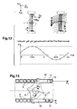
- the variation of the pitch angles ⁇ of the one rotor blade 5 is shown with one curve of the diagram of Fig. 10 while the variation of the pitch angles ⁇ of each next rotor blade 5 in circumferential direction is shown with the opposed curve of said diagram.
- Each pitch angle ⁇ of each next rotor blade 5 in circumferential direction varies a given revolution angle ⁇ to the respectively opposite direction.
- the rotor blades 5 between 1/2 ⁇ and 3/2 ⁇ in circumferential direction of the rotor move continuously to pitch angles ⁇ alternately opposed relative to each other while the rotor blades 5 between 0° to 1 ⁇ 2 ⁇ and 3/4 ⁇ to 2 ⁇ stay respectively in neutral position.
- the variation of the pitch angles ⁇ of the one rotor blade 5 is shown with one curve of the diagram of Fig. 11 while the variation of the pitch angles ⁇ of each next rotor blade 5 in circumferential direction is shown with the opposed curve of said diagram.
- forces in x HC and z HC direction can be generated by the superposition of a moment generation perpendicular to the - rotors rotational axis y F with an anti-torque-thrust F y .
- One half of the rotor creates a high thrust in one direction, while the other half creates a low thrust in the other direction.
- the low thrust flow is used to redirect the high thrust flow, resulting in total in a force F z in z HC - direction.
- a force F x and again a moment M yF is generated supplemental to a desired force F z
- M xF , M yF and M zF are calculated by summing up the cross products of the forces F B and F D in Cartesian vector notation and their individual radii of application r F (see Fig. 9 ) to the rotor center in vector notation for all blades.
- Fig. 12 depicts the generation of a desired force F z .
- M ⁇ xyzF ⁇ N F ⁇ B ⁇ r ⁇ F
- M ⁇ xyzF M xF M yF M zF
- F ⁇ B F Dx F B F Dz
- r ⁇ F r Fx 0 r Fz .
- Fig. 13 corresponding features are referred to with the same references as in Figure 1 - 12 .
- pitch variation the distance of the permanent magnets 13, 14 on the rotor relative to the rotor plane 12 and relative to the electromagnets 9 in the shroud 2 changes, which can lead to a non-optimal location for inductive interaction.
- a shifting system shifting the electromagnets in y HC -direction is provided.
- a width y M and/or a length x M of the permanent magnets 13, 14 is increased, so that the permanent magnets 13, 14 cover the electromagnets 9 at all pitch angles ⁇ .
- the permanent magnets 13, 14 are mounted on an end of a lever 18 rotatable relative to an axis parallel to the pitch axis with its hinge at the position of the permanent magnets 13, 14, while a system is provided preventing the permanent magnets 13, 14 to leave the rotational plane 12 of the electromagnets 9.
- the rotor drive system 1 can be used to control blade pitch in any thrust generating rotational system or systems which draw power from the movement of the surrounding air like wind turbines.
Landscapes
- Engineering & Computer Science (AREA)
- Mechanical Engineering (AREA)
- Aviation & Aerospace Engineering (AREA)
- Structures Of Non-Positive Displacement Pumps (AREA)
Description
- The invention relates to a rotor drive system, particularly a rotor drive system of a tail rotor of a helicopter with the features of the preamble of
claim 1. - In order to balance the reactive torque of a main rotor, it is known to provide helicopters with a tail rotor, driven and located in a duct, i. e. in a so called fenestron.
- Rotating thrust systems with blades controlled by a variable rotational speed instead of a variable pitch rate suffer of the problems of high torque moments and low thrust change rates, especially in the area of low rotational velocities. On the other side, thrust systems with a constant rotational speed and variable pitch often cannot lower the rotational speed or change the direction of rotation.
- The document
US 2009/140095 A1 discloses a rotary-wing aircraft with an electric motor mounted along an axis of rotation to drive a rotor system about the axis of rotation. - The document
WO 02/096752 A1 - The document
JP 2011006041 - Individual blade pitch control of turbines in wind farms is known from the document
US 2012/0051907 . - The document
US 2006/049304 A1 discloses a hover aircraft with an air impeller engine having an air channel duct and a rotor with outer ends of its blades fixed to an annular impeller disk that is driven by magnetic induction elements arrayed in the air channel duct. The air-impeller engine is arranged vertically in the aircraft frame to provide vertical thrust for vertical take-off and landing. The air-impeller engine employs dual, coaxial, contra-rotating rotors for increased thrust and gyroscopic stability. An air vane assembly directs a portion of the air thrust output at a desired angle to provide a horizontal thrust component for flight manoeuvring or translation movement. Electric power is supplied to the magnetic induction drives by high-capacity lightweight batteries or fuel cells. - According to the document
WO 2009/129309 A2 a wind generator is disclosed in which superconducting ring generators are utilized without the need for a load bearing drive shaft and other mechanical components. - The document
GB 2360752 A - The document
US 4953811 A discloses a helicopter with an electrical powered tail rotor in a shroud. At least one permanent magnet energized synchronous motor with an increased pole number drives the tail rotor. Said at least one synchronous motor is integrated as a torus around an opening of the shroud encompassing the tail rotor. Blades of the tail rotor are fixed to at least one rotating component. - Another example of prior art is provided by document
CA 2794077 A . - Until now, the anti-torque thrust system of helicopters is usually operating at a constant rotational speed and the change in thrust is usually generated by a variable rotor blade pitch. A thrust system where a change of thrust is generated by changing the blade pitch has several advantages compared to a thrust system where the rotational speed is changed. The change in thrust can be set very fast, just limited by the pitch change rate of the blades while the thrust change by a change in rotational speed is usually much slower due to the required acceleration and deceleration of the rotor. A thrust change by variable pitch causes just low changes in the torque of the rotational axis in contrast to a thrust change by a variable rotational speed, where the whole rotor mass needs to be accelerated, leading to a high rotor torque. This is not just of advantage for the power requirement of the driving system, but also for the moment equilibrium of a helicopter or any other system where the thrust system is built in. A thrust system which combines the two features, variable rotational speed and variable pitch is usually more complex because in addition to a drive which allows a variable rotational speed, also a system for changing the pitch needs to be built in. This increased complexity makes such a concept more expensive and heavy.
- It is an object of the invention to provide an improved rotor drive system, improve reaction times of said rotor drive system and to increase the degrees of freedom of such a rotor drive system. It is a further object of the invention to improve the vibration control and sound control of such a rotor drive system, particularly for a rotor drive system as a ducted fan for generating anti-torque for a helicopter at variable rotational speeds.
- According to the invention a rotor drive system, particularly a rotor drive system of a tail rotor of a helicopter, comprises a stator and a rotor. Said rotor is mounted to the stator with a rotatable central carrier and rotor blades are radially attached to said rotatable central carrier. Said rotor blades define a rotation plane with their radial central axes said rotation plane being essentially perpendicular to an axis of rotation of the rotor. Each of said rotor blades is pivotable about their respective radial central axis for variation of blade pitch. Drive means and pitch control means are provided for said rotor. Along at least one blade radius on said rotor blades at least one permanent magnet is provided on each rotor blade and a plurality of electromagnets on the stator are provided coaxially on at least one stator radius close enough to said at least one blade radius to allow inductive interaction between said electromagnets on the stator and said at least one permanent magnet on each rotor blade. Said permanent magnets are fixed to the respective rotor blades, offset from the radial central axis in direction of the axis of rotation of the rotor, for individual pitch control of said rotor blades by individual control of the electromagnets individually connected to electric supply means. An inventive rotor drive system comprises a central carrier as a hub with one preferably electrical hub motor as drive means providing power to the rotor while the individually controllable electromagnets on the stator and said at least one permanent magnet on each rotor blade mainly provide the pitch control for the twist of the respective rotor blades individually controllable by control units. The inventive rotor drive system allows control of the blade pitch by a single system. The inventive rotor drive system further allows additional degrees of freedom by moment generation about the axes perpendicular to the rotors rotational axis and in the direction of the axis of rotation of the rotor. The inventive rotor drive system also allows individual high frequency pitch change for the respective rotor blades. The electromagnets on the stator and said at least one permanent magnet on each rotor blade can be mounted for example on a radius corresponding to the connection between the rotor blades and flex-beams fixing the rotor blades to the central carrier. In this case the at least one ring of electromagnets must be mounted on an additional support ring as stator allowing the use of this invention for conventional, unshrouded tail rotors or even main rotors of helicopters.
- According to a preferred embodiment of the invention the stator is a ducted fan and the rotor is mounted on the central carrier radially inside the ducted fan. According to this advantageous embodiment of the invention in ducted fan rotors, the at least one ring of electromagnets can be mounted on the duct so that no additional support ring as stator is required. Each of said rotor blades of the rotor is provided with two electrically separated permanent magnets at a tip of each rotor blade and each of said two permanent magnets is fixed offset from the radial central axis in direction of the axis of rotation of the rotor on opposed sides to the rotation plane. The electromagnets are provided along two coaxial, electrically separate rings on an inner circumference of the ducted fan next to the tips with one of said separate rings being sufficiently close to said permanent magnets on one of said two opposed sides and the other one of said separate rings being sufficiently close to said permanent magnets on the other one of said two opposed sides to the rotation plane to allow electrically separate induction of said permanent magnets on both of the opposed sides of each rotor blade. An advantage of the invention is the provision of pitch control means for the rotor blades individually for each rotor blade for any position of the rotor blade along its circular path. No separate systems for generating variable rotation speed of the entire rotor and pitch control of the individual blades are required. The inventive rotor drive system allows a combination of electromagnets provided along one ring with said permanent magnets offset on one and the same side or electromagnets provided along two coaxial, electrically separate rings with associated permanent magnets offset on either sides as outer motors/generators in the ducted fan with one hub motor providing additional power. The outer motor(s)/generators would provide differentiated power for the twist of the rotor blades whilst the hub motor would provide power to drive the rotor. The motors of the inventive rotor drive system are preferably electrically driven. If the rotor of the inventive rotor drive system is driven mechanically, the preferably electrical outer motors for pitch control of the rotor blades with additional degrees of freedom like MxF, MyF and MzF moment generation, Fx and Fz force generation and high frequency pitch change could as well be controlled as a coupled Generator-Motor-System, so that e. g. the electromagnets on the stator and said at least one permanent magnet on each rotor blade act as a generator fed by the energy of the hub motor with both outer motors contributing to the required pitch moment generation as pitch control means for controlled pitch change of the rotor blade. When both outer electrical motors of the inventive rotor drive system act as generators supplying power to an electrical grid of e. g. a helicopter, existing generators on board the helicopter would be obsolete. In this case, for a pitch change, just the electricity generation balance between both outer electric generators of the inventive rotor drive system would need to be adjusted, which can be done by motor control units.
- According to a further preferred embodiment of the invention the ducted fan of the inventive rotor drive system provides anti-torque, particularly like a ducted tail rotor of a helicopter in a shroud. The drive means for said rotor are the electromagnets of the two separate rings on the inner circumference of the ducted fan interacting with said permanent magnets on both of the opposed sides of each rotor blade to operate as electrically separated motors.
- Assuming no aerodynamic pitch moments about the pitch axis of the blades when both outer motors of the inventive rotor drive system provide the same power forces F1 and F2 generated by the motor are equal. When the two motors provide different amounts of power, a moment MB is generated in the blades central axis, allowing individual pitch changes Δα of each individually driven rotor blade for F1>F2 and for F1<F2. The amount of respective individual pitch changes Δα is determined by the applied moment and the torsional stiffness of the rotational ball bearing support for pitch with a torsional spring or by the torsional stiffness of the flex-beam on which the blade is mounted. Aerodynamic pitch moments are taken into account as well by a motor control or particularly an active motor control system of said drive means and pitch control means.
- The inventive rotor drive system in a ducted fan allows reduced rotational speeds independent from the speed of the main rotor with the advantage that the noise generated at lower thrust with lower rotational speeds is usually lower than at a system with a constant, high rotational speed. Supply means are provided separately to each of said electro magnets of said at least two motors. Consequently an advantage of the inventive rotor drive system in a ducted fan is that the blade pitch of the rotor blades can be controlled individually by the electro magnets of the two rings, providing a force difference at the permanent magnets on opposed sides individually for each blade. The inventive system also provides additional redundancy, because it is still operable if one of the two outer motors/generators or individual electromagnets fail.
- All together the inventive rotor drive system provides the following advantages:
- Combined advantages of rotors with variable rotational speed and variable pitch with a single drive/control unit,
- No additional complexity by using the same drive system for rotation and pitch,
- The inventive rotor drive system can be switched off,
- The inventive rotor drive system provides variable rotational speed in both turn-directions,
- The inventive rotor drive system is therefore more energy efficient compared to state of the art systems,
- The inventive rotor drive system is therefore in most cases more silent and in no case noisier,
- The inventive rotor drive system provides variable pitch,
- The inventive rotor drive system can provide very fast changes in thrust, even faster than conventional systems with variable pitch,
- The inventive rotor drive system allows individual control of the pitch angle of each blade to:
- ∘ Generate moments MxF and MzF in the axes xHC and zHC perpendicular to the rotors rotational axis yF which provides two additional degrees of freedom compared to the collective variable pitch systems of the state of the art.
- ∘ Generate a controllable moment MyF in the rotational axis of the rotor by pitching over the circumference respectively two blades constantly in opposite directions ±α to generate a circumferential drag force FD opposite to the rotational direction of the rotor and consequently a moment MyF, but in total no resulting thrust ΔFy.
- ∘ Generate forces in xHC and zHC direction by drag generation in circumferential direction at just a part of the rotor azimuth for Fx and for Fz. The generation of drag forces always leads also to the generation of a moment MyF. Alternatively forces Fx and/or Fz in xHC and zHC direction can be generated by the superposition of a moment generation MxF and/or MzF perpendicular to the rotors rotational axis yHc with an anti-torque-thrust Fy. One half of the rotor creates a high thrust in one direction, while the other half creates a low thrust, e. g. in the other direction. The low thrust flow interacts with the high thrust flow to redirect the high thrust flow, resulting in total in a force Fx in xHC-direction and/or Fz in zHC-direction. Again a moment MyF is generated by the drag in circumferential direction supplemental to the desired force Fx or Fz.
- ∘ Use the fan as a vibration control system
- ∘ Reduce or modify the noise caused by the fan
- The inventive rotor drive system allows redundancy if one of the motors or some of the electromagnets fail.
- Due to the instantaneous force changes made possible by the high control frequency of the electromagnets, the pitch can be changed much faster compared to conventional systems. In combination with the individual pitch control and the variable rotational speed, this opens a wide field of possibilities for its use in the flight control, stabilization, sound control and anti-vibration system of a helicopter.
- The rotational speed of the inventive rotor drive system can be adjusted continuously. This can be used to lower the maximum thrust level and the power consumption in flight states when a maximum thrust level is not required. The inventive rotor drive system allows, when it is not required, to hold the rotor blades in a constant position and to still actively control the blade pitch in this situation. In a system without or with a very small shroud, where the rotor blades are still partly, or fully exposed to a free air stream, the pitch control of the non-rotating blades could be used to let the non-rotating blades act like a rudder.
- Preferred embodiments of the invention are presented by means of the following description with reference to the attached drawings, from which
- in
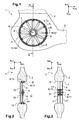
Figure 1 a lateral view of a tail rotor of a rotor drive system according to the invention is shown, - in
Figure 2 a cross-section A-A ofFig. 1 is shown, - in
Figure 3 a cross-section A-A is shown of a further rotor drive system according to the invention, - in
Figure 4 a rotor blade with a positive pitch angle α in a projection of a part of the rotor drive system according to the invention is shown, - in
Figure 5 a rotor blade with a pitch angle α = 0° in a projection of said part of the rotor drive system according to the invention is shown, - in
Figure 6 a rotor blade with a negative pitch angle α in a projection of said part of the rotor drive system according to the invention is shown, - in
Figure 7 - Figure 12 different blade pitches α over one rotor revolution are shown with their respectively resulting forces and moments, - in
Figure 13 a rotor blade in a further modified rotor drive system according to the invention is shown. - Two coordinate systems are used throughout the description:
- A first coordinate system with the coordinates xHC, yHC and zHC is cartesian with a helicopter's frame as reference. The xHC-axis is pointing towards the front of the helicopter in forward flight direction. The yHC-axis is pointing to the right of the helicopter clockwise in forward flight direction. The zHC-axis completes the right hand system by pointing down towards a bottom of the helicopter. The second coordinate system is a rotor fixed polar coordinate system inherent to any individual rotor blade of the rotor drive system. Relative to the helicopter's frame of reference the second system rotates with the rotational speed of the rotor about an axis of rotation yF which is parallel to yHC. Each rotor blade possesses its own second coordinate system. It is defined by the radial axis r of the rotor blade pointing from the rotor hub centre to the tip center of the rotor blade and the circumferential coordinate cF, within the rotational plane of the rotor. A revolution angle ψ describes an angular position of the rotor blade of the rotor drive system with regard to the helicopter's frame of reference. The rotation of the rotor blade around the radial axis r by the pitch angle α (i. e.
Figure 6 ) completes the second coordinate system. - According to
Figure 1 arotor drive system 1 in a ducted fan as an anti-torque system, e. g. an electrical Fenestron, is mounted into ashroud 2 connected to atail boom 3 of a helicopter (not shown). Theshroud 2 is constructed as a circular open stator. Inside theshroud 2 is a rotor with a rotatablecentral carrier 4 and a plurality ofrotor blades 5, i. e. twelverotor blades 5, distributed around thecentral carrier 4 in essentially one plane perpendicular to the axis of rotation yF of the rotatablecentral carrier 4 and rotatable with thecentral carrier 4 around said axis of rotation yF. The rotor is mounted by means of thecentral carrier 4 into said ducted fan with said stator. Each of saidrotor blades 5 is mounted by means of a rotational ball borne support for pitch with torsional spring or a flex-beam 6 with an inner end to thecentral carrier 4. Therotor blades 5 extend radial from saidcentral carrier 4 withtips 7 towards the circular open stator at aninner circumference 8 of the ducted fan in theshroud 2.Said tips 7 are respectively perrotor blade 5 provided with twopermanent magnets - A plurality of
electro magnets 9 of the circular open stator are provided coaxially with thecentral carrier 4. Saidelectro magnets 9 are each integrated along theinner circumference 8 of theshroud 2 encompassing the separatepermanent magnets tips 7 of therotor blades 5 without obstructing free rotation of therotor blades 5. - The
electro magnets 9 with the separatepermanent magnets - According to
Fig. 2 corresponding features are referred to with the same references as inFigure 1 . Theshroud 2 of therotor drive system 1 with a ducted fan comprises the in direction of the axis of rotation yF circular open stator. Inside the circular open stator is the rotor with the rotatablecentral carrier 4 and therotor blades 5 distributed around thecentral carrier 4 in the essentially one plane perpendicular to the axis of rotation yF. The rotatablecentral carrier 4 is mounted with unilateral radial struts 16 into said ducted fan with said stator. Each of saidrotor blades 5 is mounted by means of a rotational ball borne support for pitch with torsional spring or a flex-beam 6 with the inner end to thecentral carrier 4. Therotor blades 5 extend radial from saidcentral carrier 4 withtips 7 towards theinner circumference 8 of the ducted fan in theshroud 2.Said tips 7 are respectively perrotor blade 5 provided with twopermanent magnets - The
electro magnets 9 of the circular open stator are aligned along theinner circumference 8 of the ducted fan in theshroud 2 in two essentiallyparallel rows - According to
Fig. 3 corresponding features are referred to with the same references as inFigure 1, 2 . Theshroud 2 of therotor drive system 1 with a ducted fan comprises the in direction of the axis of rotation yF circular open stator. Inside the circular open stator is the rotor with the rotatablecentral carrier 4 and therotor blades 5 distributed around thecentral carrier 4 in the essentially one plane perpendicular to the axis of rotation yF. The rotatablecentral carrier 4 is mounted with bilateral radial struts 17 into said ducted fan with said stator. Each of saidrotor blades 5 is mounted by means of the rotational ball borne support for pitch with torsional spring or the flex-beam 6 with the inner end to thecentral carrier 4. Therotor blades 5 extend radial from saidcentral carrier 4 withtips 7 towards theinner circumference 8 of the ducted fan in theshroud 2. Respectively twopermanent magnets rotor blade 5 are provided at the inner end of each of saidrotor blades 5 with separation of said twopermanent magnets - The
electro magnets 9 of the circular open stator are aligned along anouter circumference 8 of thecentral carrier 4 in two essentiallyparallel rows - According to
Figures 4 - 6 corresponding features are referred to with the same references as inFigure 1 - 3 . The plurality ofelectro magnets 9 are aligned to therespective rows inner circumference 8 of the ducted fan in theshroud 2, each with a distance dM to amiddle rotation plane 12 through the radial central axis r of pivoting of eachrotor blade 5. Therespective rows inner circumference 8 of the ducted fan in theshroud 2. Each of theelectromagnets 9 is individually connected to a phase of electrical supply from coupled individual control units (not shown). The individual control units supply at least threeelectromagnets 9 in the vicinity of thepermanent magnets permanent magnet rotor blades 5 are individually controllable, eachelectromagnet 9 in the vicinity of eachrotor blade 5 needs to have an own controller which creates the required magnetic field by controlling the current rating dependent on the rotor position, the actual blade pitch and the commanded forces F1 and F2. - The
electro magnets 9 of therespective rows - 1. A top level controller for the whole electrical fan system. The output of the top level controller is input for
level 2 blade controllers. - 2. A blade controller for control of the interaction of the two linear motors of an
individual rotor blade 5 dependent on the inputs of the top level controller. The blade controller commands the magnet controllers of theindividual rotor blades 5. - 3. The magnet controller manages the time dependent force generated by one linear motor by controlling the associated
electromagnets 9 in the vicinity of the twopermanent magnets - For each permanent magnet an individual magnet controller is provided for control of the
electromagnets 9 in the vicinity of saidpermanent magnet permanent magnet rotor blade 5 to which the magnet controller is connected to and a detector for the azimuthal position of the rotor in order to provide control of the magnets depending on the position of therotor blade 5 relative to theelectromagnets 9. Thus each "permanent magnet" - "magnet controller" - "associated electromagnets" - combination can be considered as an individual linear motor. - The two individual linear motors of the two
rows rotor blade 5 are then controlled by a higher level controller with as input the pitch and blade force command in combination with the current pitch α. The azimuthal position, indicated by the revolution angle ψ, is provided by means of an azimuth angle measurement system of therotor blade 5. The input commands for the blade controllers are again generated by the top level controller which gets as command the required rotor thrust and moments, and the frequency and phase requirements from potential noise and vibration control controllers. - A blade pitch axis with
tip 7 of eachrotor blade 5 is half way in between said tworows electro magnets 9. Twopermanent magnets tips 7 of therotor blades 5 by a magnet-blade connector plate 15. The twopermanent magnets rotor blade 5 in direction of the rotation axis yF of the rotor to coincide with therespective rows electro magnets 9 for the provision of electro magnet motors/generators depending from the electrical supply of the three phase alternating current. - Two separate motors of respective
permanent magnets electro magnets 9 generate the forces F1 and F2 on eachrotor blade 5 of the rotor in circumferential direction cF with the distance dm parallel to therotation plane 12 of therotor blades 5. - When - additional to a drive force -, the forces F1 and F2 generated by the two separate motors differ, a Motor Moment MB = (F1 - F2)*dm results about the blade pitch axis of the
respective rotor blade 5. Said moment changes the pitch angle α of therotor blade 5 determined by the torsional stiffness of the flexbeam 6 (seeFig. 4 or 6 ). When the forces F1 and F2 are equal, the torsional stiffness of theflexbeam 6 holds therotor blade 5 in its neutral position (seeFig. 5 ). The pitch angle α of therotor blade 5 leads to an aerodynamically resulting force FB (seeFig. 4 or 6 ) perpendicular to the rotor plane and a Drag force FD in circumferential direction cF. The sum of forces FB of allN rotor blades 5 results in the total rotor force Fy in yF direction with
- A blade pitch sensor (not shown) is provided for each
rotor blade 5 for active control of the blade pitch angle α by the control units. Said active blade pitch control system corrects any pitch angle offset by an active and preferably individual control of F1 and F2 of eachrotor blade 5. An individual blade pitch control comprises the rotor azimuth angle measurement system, which determines the exact blade positions. According to the detected exact positions of therotor blade 5 the control units supply individually the three phase alternating current to the electromagnets of theconcerned rotor blade 5. - According to
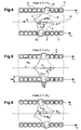
Figure 7 corresponding features are referred to with the same references as inFigure 1 - 6 . Along one entire rotation of the rotor each rotor blade moves from the revolution angle ψ = 0° to the revolution angle ψ = 360° corresponding to 2 π. The revolution angle ψ = 0° and the revolution angle ψ = 360° are aligned on the xHC-axis pointing towards the front of the helicopter in forward flight direction. The revolution angle ψ = 90° and the revolution angle ψ = 270° are aligned on the zHC-axis. Respective pitch angles α of onerotor blade 5 along one entire rotation of the rotor from the revolution angle ψ = 0° to the revolution angle ψ = 2 π are indicated with the respective revolution angle ψ. The pitch angles α of onerotor blade 5 vary from 0° at the revolution angle ψ = 0° to a maximum at the revolution angle ψ = π/2, back to 0° at a revolution angle ψ = π, again to a maximum at the revolution angle ψ = 3/2 π opposed to the maximum at the revolution angle ψ = π/2 and is back to 0° at the revolution angle ψ = 2 π, and so on for the next revolutions of the rotor. - A force FB to each
rotor blade 5 is related to each pitch angle of eachrotor blade 5 between the revolution angle ψ = 0° to the revolution angle ψ = 2 π. The sum of forces FB of allrotor blades 5 of the rotor between the revolution angle ψ = 0° to the revolution angle ψ = 2 π results in the total rotor force in y direction
- The moment MxF is calculated by summing up the cross products of the forces FB in Cartesian vector notation and their individual radii of application rz to the rotor center in vector notation for all blades.
- According to
Figure 8 corresponding features are referred to with the same references as inFigure 1 - 7 . The pitch angles α of onerotor blade 5 vary from a maximum at the revolution angle ψ = 0° to 0° at the revolution angle ψ = π/2, back to a maximum at the revolution angle ψ = π opposed to the maximum at the revolution angle ψ = 0°, again to 0° at the revolution angle ψ = 3/2 π and is back to the maximum of the revolution angle ψ =0° at the revolution angle ψ = 2 π, and so on for the next revolutions of the rotor. - A force FB to each
rotor blade 5 is related to each pitch angle of eachrotor blade 5 between the revolution angle ψ = 0° to the revolution angle ψ = 2 π. The sum of forces FB of allrotor blades 5 of the rotor between the revolution angle ψ = 0° to the revolution angle ψ = 2 π results in the total rotor force in y direction
- According to
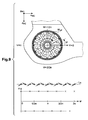
Figure 9 corresponding features are referred to with the same references as inFigure 1 - 8 . The pitch angle α of onerotor blade 5 is constantly at a maximum over the whole revolution of the rotor. Each pitch angle α of each respectivelynext rotor blade 5 in circumferential direction is constantly at a maximum opposed to the pitch angle α of the onerotor blade 5 over the whole revolution of the rotor. Thus all of therotor blades 5 are fixed in alternately opposed maxima relative to each other over the whole revolution of the rotor. - A force FB to each
rotor blade 5 related to each pitch angle of eachrotor blade 5 is compensated by the force FB related to the pitch angle of thenext rotor blade 5 in circumferential direction between the revolution angle ψ = 0° to the revolution angle ψ = 2 π, while a drag force FD from eachrotor blade 5 results. The moment MyF is calculated by summing up the cross products of the drag forces FD in Cartesian vector notation and their individual radii of application r to the rotor center in vector notation for all blades. - according to
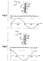
Figure 10 corresponding features are referred to with the same references as inFigure 1 - 9 . Pitch angles α of onerotor blade 5 vary continuously from 0° at the revolution angle ψ = 0° to a maximum at the revolution angle ψ = π/2 and back to 0° at a revolution angle ψ = π. Each pitch angle α of eachnext rotor blade 5 in circumferential direction between 0° and π varies a given revolution angle ψ of the neighbouringrotor blade 5 to the respectively opposite direction. Thus therotor blades 5 between 0° and π in circumferential direction of the rotor move continuously to pitch angles α alternately opposed relative to each other while therotor blades 5 between π and 2 π stay respectively in neutral position. The variation of the pitch angles α of the onerotor blade 5 is shown with one curve of the diagram ofFig. 10 while the variation of the pitch angles α of eachnext rotor blade 5 in circumferential direction is shown with the opposed curve of said diagram. - A force FB to each
rotor blade 5 related to each pitch angle α of eachrotor blade 5 is compensated by the force FB related to the pitch angle α of thenext rotor blade 5 in circumferential direction between the revolution angle ψ = 0 to the revolution angle ψ = 2 π, while a drag force FD from eachrotor blade 5 results. The drag forces FD are just generated between the revolution angle ψ = 0 and angle ψ = π. Consequently the part of any circumferential drag force FD which acts in xHC direction between angle ψ = 0 and angle ψ = π is not compensated by an equivalent force between angle ψ = = π and angle ψ = 2 π, which leads in total to a force Fx in xHC direction. - According to
Figure 11 corresponding features are referred to with the same references as inFigure 1 - 10 . Pitch angles α of onerotor blade 5 vary from 0° from the revolution angle ψ = π/2 to a maximum at the revolution angle ψ = π and back to 0° at a revolution angle ψ = 3/2 π. Each pitch angle α of eachnext rotor blade 5 in circumferential direction varies a given revolution angle ψ to the respectively opposite direction. Thus therotor blades 5 between 1/2 π and 3/2 π in circumferential direction of the rotor move continuously to pitch angles α alternately opposed relative to each other while therotor blades 5 between 0° to ½ π and 3/4 π to 2 π stay respectively in neutral position. The variation of the pitch angles α of the onerotor blade 5 is shown with one curve of the diagram ofFig. 11 while the variation of the pitch angles α of eachnext rotor blade 5 in circumferential direction is shown with the opposed curve of said diagram. - A force FB to each
rotor blade 5 related to each pitch angle of eachrotor blade 5 is compensated by the force FB related to the pitch angle of thenext rotor blade 5 in circumferential direction between the revolution angle ψ = 0 to the revolution angle ψ = 2 π, while a drag force FD from eachrotor blade 5 results. The drag forces FD are just generated between the revolution angle ψ = π/2 and angle ψ = 3/2 π. Consequently the part of any circumferential drag force FD which acts in zHC direction between angle ψ = π/2 and angle ψ = 3/2 π is not compensated by an equivalent force between angle ψ = 3/2 π and angle ψ = π/2, which leads in total to a force Fz in zHC direction. - According to
Figure 12 corresponding features are referred to with the same references as inFigure 1 - 11 . The pitch angles α of onerotor blade 5 vary between a maximum at the revolution angle ψ = π/2 and a maximum at the revolution angle ψ = 3/2 π opposed to and half of the maximum at the revolution angle ψ = π/2 and so on for the next revolutions of the rotor. - Alternatively forces in xHC and zHC direction can be generated by the superposition of a moment generation perpendicular to the - rotors rotational axis yF with an anti-torque-thrust Fy. One half of the rotor creates a high thrust in one direction, while the other half creates a low thrust in the other direction. The low thrust flow is used to redirect the high thrust flow, resulting in total in a force Fz in zHC- direction. Also a force Fx and again a moment MyF is generated supplemental to a desired force Fz
- With the respective halves of high thrust and low thrust shifted each with π/2 relative to the pitch angles α shown - a force Fx in xHC-direction results correspondingly., Supplemental to the desired force Fx, a force Fz and a moment MyF is generated.
- Thus the moments MxF, MyF and MzF are calculated by summing up the cross products of the forces FB and FD in Cartesian vector notation and their individual radii of application rF (see
Fig. 9 ) to the rotor center in vector notation for all blades.Fig. 12 depicts the generation of a desired force Fz.
- According to
Fig. 13 corresponding features are referred to with the same references as inFigure 1 - 12 . With pitch variation, the distance of thepermanent magnets rotor plane 12 and relative to theelectromagnets 9 in theshroud 2 changes, which can lead to a non-optimal location for inductive interaction. A shifting system shifting the electromagnets in yHC-direction is provided. Alternatively a width yM and/or a length xM of thepermanent magnets permanent magnets electromagnets 9 at all pitch angles α. Or, further alternatively, thepermanent magnets lever 18 rotatable relative to an axis parallel to the pitch axis with its hinge at the position of thepermanent magnets permanent magnets rotational plane 12 of theelectromagnets 9. - The
rotor drive system 1 can be used to control blade pitch in any thrust generating rotational system or systems which draw power from the movement of the surrounding air like wind turbines. -
- 1
- rotor drive system
- 2
- shroud
- 3
- tail boom
- 4
- rotatable central carrier
- 5
- rotor blades
- 6
- flex-beam
- 7
- tips
- 8
- inner circumference
- 9
- electro magnets
- 10
- row
- 11
- row
- 12
- rotation plane
- 13
- permanent magnet
- 14
- permanent magnet
- 15
- magnet-blade connector plate
- 16
- unilateral radial strut
- 17
- bilateral radial strut
- 18
- lever
Claims (10)
- A rotor drive system (1), particularly a rotor drive system of a tail rotor of a helicopter, said system (1) comprising- a stator (2) and a rotor, said rotor being mounted to the stator (2) with a rotatable central carrier (4) and rotor blades (5) radially attached to said rotatable central carrier (4), said rotor blades (5) defining one rotation plane (12) with their radial central axes and each of said rotor blades (5) being pivotable about their respective radial central axis for variation of blade pitch,- drive means (10, 11) for said rotor, and- pitch control means for said pivotable rotor blades (5),characterized in that along at least one blade radius at least one permanent magnet (13, 14) is provided on each rotor blade (5) and a plurality of electromagnets (9) on the stator (2) are provided coaxially on at least one stator radius close enough to said at least one blade radius to allow inductive interaction between said plurality of electromagnets (9) and said at least one permanent magnet (13, 14) on each rotor blade (5), said permanent magnets (13, 14) being fixed to the rotor blades (5) offset from the radial central axis in a direction perpendicular to the rotation plane (12) for individual pitch control of said rotor blades (5) by individual control of the electromagnets (9) connected to electric supply means.
- The system (1) according to claim 1,
characterized in that the stator (2) is a ducted fan, the rotor is mounted radially inside the ducted fan, each of said rotor blades (5) is provided with two electrically separated permanent magnets (13, 14) at a tip (7) of each rotor blade (5), each of said two permanent magnets (13, 14) is fixed offset from the radial central axis in the direction perpendicular to the rotation plane (12) on opposed sides to the rotation plane (12) and the electromagnets (9) are provided along two coaxial, electrically separate rings on an inner circumference of the ducted fan next to the tips (7), each of said separate rings being sufficiently close to said permanent magnets (13, 14) on one of the opposed sides to allow electrically separate induction of said permanent magnets (13, 14) on both of the opposed sides of each rotor blade (5). - The system (1) according to claim 2,
characterized in that the ducted fan is an anti-torque system, particularly a ducted tail rotor of a helicopter, in a shroud (2) and the drive means for said rotor are the electromagnets (9) of the two separate rings on the inner circumference of the ducted fan operated as individually controlled motors. - The system (1) according to claim 2,
characterized in that the central carrier (4) is a driven hub and the electromagnets (9) provided along the two separate rings on the inner circumference of the ducted fan are operated as electrically separated generators for supply of power to electric consumers. - The system (1) according to claim 3,
characterized in that said electromagnets (9) are respectively supplied with three phase alternating current from coupled individual control units. - The system (1) according to claim 1,
characterized in that each rotor blade (5) is provided at its tip (7) with a magnet blade connector (15) extending essentially in the both directions of the axis of rotation with one permanent magnet (13, 14) at each of its bilateral ends, each of said permanent magnets (13, 14) being coincident with said electro magnets (9) of one of said at least two separate motors (10, 11). - The system (1) according to claim 1,
characterized in that a rotor azimuth angle measurement system is provided for determination of exact circumferential positions of each rotor blade (5). - The system (1) according to claim 1,
characterized in that a shifting system is provided for the electromagnets (9) in a yHC-direction. - The system (1) according to claim 1,
characterized in that the permanent magnets (13, 14) are mounted at the end of a lever rotatable in an axis parallel to the pitch axis with its hinge at the position of the permanent magnets (13, 14). - The system (1) according to claim 1,
characterized in that a ring is provided connecting the individual tips (7) of the rotor blades (5).
Priority Applications (3)
| Application Number | Priority Date | Filing Date | Title |
|---|---|---|---|
| EP13400014.0A EP2821344B1 (en) | 2013-07-02 | 2013-07-02 | Rotor drive system |
| US14/300,533 US9758245B2 (en) | 2013-07-02 | 2014-06-10 | Rotor drive system |
| KR1020140075160A KR101662284B1 (en) | 2013-07-02 | 2014-06-19 | Rotor drive system |
Applications Claiming Priority (1)
| Application Number | Priority Date | Filing Date | Title |
|---|---|---|---|
| EP13400014.0A EP2821344B1 (en) | 2013-07-02 | 2013-07-02 | Rotor drive system |
Publications (2)
| Publication Number | Publication Date |
|---|---|
| EP2821344A1 EP2821344A1 (en) | 2015-01-07 |
| EP2821344B1 true EP2821344B1 (en) | 2015-10-14 |
Family
ID=49034021
Family Applications (1)
| Application Number | Title | Priority Date | Filing Date |
|---|---|---|---|
| EP13400014.0A Active EP2821344B1 (en) | 2013-07-02 | 2013-07-02 | Rotor drive system |
Country Status (3)
| Country | Link |
|---|---|
| US (1) | US9758245B2 (en) |
| EP (1) | EP2821344B1 (en) |
| KR (1) | KR101662284B1 (en) |
Cited By (3)
| Publication number | Priority date | Publication date | Assignee | Title |
|---|---|---|---|---|
| RU2649838C1 (en) * | 2017-01-27 | 2018-04-04 | Леонид Александрович Тарасов | Blade electromagnetic thruster |
| EP3597539A1 (en) | 2018-07-17 | 2020-01-22 | AIRBUS HELICOPTERS DEUTSCHLAND GmbH | A rotor with pitch control apparatus |
| US11220332B2 (en) | 2019-11-19 | 2022-01-11 | Airbus Helicopters Deutschland GmbH | Rotor with pitch control apparatus |
Families Citing this family (25)
| Publication number | Priority date | Publication date | Assignee | Title |
|---|---|---|---|---|
| DE102013013849A1 (en) * | 2013-08-20 | 2015-03-12 | Astrium Gmbh | Landing system for an aircraft or spacecraft |
| CN105222742A (en) * | 2014-05-26 | 2016-01-06 | 通用电气公司 | Slurry is apart from fault detection system and method |
| DE102015209673A1 (en) * | 2015-05-27 | 2016-12-01 | Siemens Aktiengesellschaft | Drive unit for an aircraft, aircraft with a drive unit and use of a double coil actuator motor |
| FR3036789B1 (en) * | 2015-05-29 | 2017-05-26 | Airbus Helicopters | METHOD OF ESTIMATING THE INSTANTANEOUS MASS OF A ROTATING WING AIRCRAFT |
| CN105156225B (en) * | 2015-09-23 | 2017-03-22 | 海门韵田电气机械科技有限公司 | Three-level compressed-air ducted fan engine |
| CN105691609A (en) * | 2016-01-13 | 2016-06-22 | 安徽理工大学 | Self-driven integration rotor wing device |
| CN105539794A (en) * | 2016-02-23 | 2016-05-04 | 张家港江苏科技大学产业技术研究院 | Variable pitch underwater propulsion system |
| US10703471B2 (en) | 2016-06-03 | 2020-07-07 | Bell Helicopter Textron Inc. | Anti-torque control using matrix of fixed blade pitch motor modules |
| US10526085B2 (en) | 2016-06-03 | 2020-01-07 | Bell Textron Inc. | Electric distributed propulsion anti-torque redundant power and control system |
| US10377479B2 (en) | 2016-06-03 | 2019-08-13 | Bell Helicopter Textron Inc. | Variable directional thrust for helicopter tail anti-torque system |
| NO342415B1 (en) * | 2016-08-31 | 2018-05-22 | FLIR Unmanned Aerial Systems AS | Controlling blade pitch by a plurality of electric motors |
| US11186185B2 (en) | 2017-05-31 | 2021-11-30 | Textron Innovations Inc. | Rotor brake effect by using electric distributed anti-torque generators and opposing electric motor thrust to slow a main rotor |
| FR3068953B1 (en) * | 2017-07-13 | 2019-11-22 | Yann Willinger | DEVICE FOR DIRECT CONTROL OF BLADE BY ELECTROMECHANICAL ACTUATOR |
| JP2020531366A (en) * | 2017-08-23 | 2020-11-05 | ヴィマアン ロボティクス, インコーポレイテッド | Drive mechanism |
| EP3501983B2 (en) | 2017-12-22 | 2025-08-20 | LEONARDO S.p.A. | Anti-torque system for a helicopter and method for controlling an anti-torque system for a helicopter |
| KR102065519B1 (en) * | 2018-01-04 | 2020-01-13 | 엘지전자 주식회사 | A Fan Able to Make Sounds and Adjust Pitch Angle |
| EP4434894A3 (en) * | 2018-04-17 | 2025-01-15 | The Maglev Aero Co. | Systems and methods for vertical takeoff and landing using magnetic levitation |
| DE102018120200A1 (en) * | 2018-08-20 | 2020-02-20 | Dr. Ing. H.C. F. Porsche Aktiengesellschaft | aircraft |
| IT201800009850A1 (en) * | 2018-10-29 | 2020-04-29 | Daniele Ciurleo | ELECTROMAGNETIC IMPULSE BRUSHLESS ELECTRIC MOTOR WITH INTEGRATED PROPELLER |
| CN109292063B (en) * | 2018-11-23 | 2023-11-03 | 上海晟钧节能科技有限公司 | Power device for deep sea diving device |
| DE102019201301B4 (en) * | 2019-02-01 | 2021-01-21 | Zf Friedrichshafen Ag | Control device for a tail rotor |
| US11673639B2 (en) * | 2019-05-11 | 2023-06-13 | Jordan McBain | Reluctance driven axial modulating mechanism for rotating shafts realizing a controllable pitch propeller/fan/turbine |
| US20200402492A1 (en) * | 2019-06-24 | 2020-12-24 | Alan Richard Greenberg | Rotor craft noise cancellation system and method |
| EP3882133A1 (en) | 2020-03-16 | 2021-09-22 | Ratier-Figeac SAS | Blade pitch actuation mechanism |
| CN114030602B (en) * | 2021-11-19 | 2023-09-05 | 中国直升机设计研究所 | Rotor system capable of actively adjusting coaxiality |
Family Cites Families (27)
| Publication number | Priority date | Publication date | Assignee | Title |
|---|---|---|---|---|
| NL6908353A (en) * | 1968-07-01 | 1970-01-05 | ||
| US4905932A (en) * | 1988-06-21 | 1990-03-06 | Piasecki Aircraft Corporation | Rotary wing aircraft shrouded propeller tail assembly |
| US4953811A (en) | 1988-10-19 | 1990-09-04 | The United States Of America As Represented By The Secretary Of The Army | Self-driving helicopter tail rotor |
| US5282719A (en) * | 1991-05-13 | 1994-02-01 | Alliedsignal Inc. | Quad mode fan pitch actuation system for a gas turbine engine |
| US5967749A (en) * | 1998-01-08 | 1999-10-19 | Electric Boat Corporation | Controllable pitch propeller arrangement |
| US6322324B1 (en) * | 2000-03-03 | 2001-11-27 | The Boeing Company | Helicopter in-flight rotor tracking system, method, and smart actuator therefor |
| GB2360752A (en) | 2000-04-01 | 2001-10-03 | Glyn Jones | Helicopter without tail rotor |
| NO313505B1 (en) | 2001-05-28 | 2002-10-14 | Simicon As | Electromagnetic operation of rotor system |
| US6354536B1 (en) * | 2000-08-08 | 2002-03-12 | Sikorsky Aircraft Corporation | Rotor hub mounted actuator for controlling a blade on a rotorcraft |
| DE20121609U1 (en) * | 2001-03-06 | 2003-04-10 | Vogel, Heribert, Dipl.-Ing., 71711 Steinheim | Remote controllable aircraft |
| US7032861B2 (en) | 2002-01-07 | 2006-04-25 | Sanders Jr John K | Quiet vertical takeoff and landing aircraft using ducted, magnetic induction air-impeller rotors |
| US6952058B2 (en) * | 2003-02-20 | 2005-10-04 | Wecs, Inc. | Wind energy conversion system |
| DE20315369U1 (en) * | 2003-10-07 | 2003-12-18 | Reinhardt, Oliver, Dipl.-Ing. | Propeller with a casing ring for an air or water vehicle has electromagnetic drive with stator to produce alternating electromagnetic fields |
| US7048506B2 (en) * | 2003-11-18 | 2006-05-23 | The Boeing Company | Method and apparatus for magnetic actuation of variable pitch impeller blades |
| WO2005100154A1 (en) * | 2004-04-13 | 2005-10-27 | Wavefront Technology Pty Ltd | System for rotor head and rotor blade |
| CN101022994B (en) * | 2004-08-30 | 2012-07-04 | 洛德公司 | Helicopter vibration control system and rotary force generator for canceling vibrations |
| CN101176383A (en) * | 2005-05-16 | 2008-05-07 | 贝尔直升机泰克斯特龙公司 | Ice handling system for tilt rotor aircraft |
| US8915710B2 (en) * | 2005-12-09 | 2014-12-23 | Sikorsky Aircraft Corporation | Brushless direct current (BLDC) motor based linear or rotary actuator for helicopter rotor control |
| US8931732B2 (en) | 2007-11-30 | 2015-01-13 | Sikorsky Aircraft Corporation | Electric powered rotary-wing aircraft |
| DE102008017460A1 (en) * | 2008-04-05 | 2009-10-15 | Howaldtswerke-Deutsche Werft Gmbh | submarine |
| WO2009129309A2 (en) | 2008-04-15 | 2009-10-22 | Sonic Blue Aerospace, Inc. | Superconducting turbine wind ring generator |
| JP4742390B2 (en) | 2009-06-23 | 2011-08-10 | ▲栄▼之 守田 | Electric motor built-in hub for rotary wing aircraft, and rotary wing aircraft using the same |
| US8029233B2 (en) * | 2010-08-31 | 2011-10-04 | General Electric Company | Wind turbine and method for controlling a wind turbine |
| US8202049B2 (en) | 2010-08-31 | 2012-06-19 | Catch the Wind, Inc. | Independent blade pitch control |
| DE102011082811A1 (en) | 2011-09-16 | 2013-03-21 | Aktiebolaget Skf | Warehouse and wind turbine |
| EP2610176B1 (en) | 2011-12-28 | 2018-02-07 | AIRBUS HELICOPTERS DEUTSCHLAND GmbH | Electrical powered tail rotor of a helicopter |
| CA2794077C (en) * | 2011-12-28 | 2015-03-31 | Eurocopter Deutschland Gmbh | Electrical powered tail rotor of a helicopter |
-
2013
- 2013-07-02 EP EP13400014.0A patent/EP2821344B1/en active Active
-
2014
- 2014-06-10 US US14/300,533 patent/US9758245B2/en active Active
- 2014-06-19 KR KR1020140075160A patent/KR101662284B1/en not_active Expired - Fee Related
Cited By (3)
| Publication number | Priority date | Publication date | Assignee | Title |
|---|---|---|---|---|
| RU2649838C1 (en) * | 2017-01-27 | 2018-04-04 | Леонид Александрович Тарасов | Blade electromagnetic thruster |
| EP3597539A1 (en) | 2018-07-17 | 2020-01-22 | AIRBUS HELICOPTERS DEUTSCHLAND GmbH | A rotor with pitch control apparatus |
| US11220332B2 (en) | 2019-11-19 | 2022-01-11 | Airbus Helicopters Deutschland GmbH | Rotor with pitch control apparatus |
Also Published As
| Publication number | Publication date |
|---|---|
| EP2821344A1 (en) | 2015-01-07 |
| US9758245B2 (en) | 2017-09-12 |
| KR20150004268A (en) | 2015-01-12 |
| KR101662284B1 (en) | 2016-10-10 |
| US20150225078A1 (en) | 2015-08-13 |
Similar Documents
| Publication | Publication Date | Title |
|---|---|---|
| EP2821344B1 (en) | Rotor drive system | |
| US11591080B2 (en) | Systems and methods for drive control of a magnetically levitated rotor | |
| EP3251952B1 (en) | Variable directional thrust for helicopter tail anti-torque system | |
| KR101958328B1 (en) | Convertiplane | |
| US9174728B2 (en) | Electrical powered tail rotor of a helicopter | |
| US7032861B2 (en) | Quiet vertical takeoff and landing aircraft using ducted, magnetic induction air-impeller rotors | |
| US9409643B2 (en) | Helicopter with cross-flow fan | |
| US6113029A (en) | Aircraft capable of hovering and conventional flight | |
| WO2004065208A2 (en) | Quiet vertical takeoff and landing aircraft using ducted, magnetic induction air-impeller rotors | |
| KR20130026506A (en) | Personal aircraft | |
| US20230088470A1 (en) | Friction limiting turbine generator gyroscope method and apparatus | |
| US11634233B2 (en) | Distributed battery bank for ducted-rotor aircraft | |
| CA3043193C (en) | A rotor with pitch control apparatus | |
| US11220332B2 (en) | Rotor with pitch control apparatus | |
| CA2794077C (en) | Electrical powered tail rotor of a helicopter | |
| US20190315461A1 (en) | Rotary-winged vehicle systems and devices | |
| EP4144637A1 (en) | Aircraft provided with supporting wings for the cruise flight | |
| US20260084807A1 (en) | Systems and methods for vertical takeoff and landing vehicle with improved rotor sizing |
Legal Events
| Date | Code | Title | Description |
|---|---|---|---|
| PUAI | Public reference made under article 153(3) epc to a published international application that has entered the european phase |
Free format text: ORIGINAL CODE: 0009012 |
|
| 17P | Request for examination filed |
Effective date: 20130702 |
|
| AK | Designated contracting states |
Kind code of ref document: A1 Designated state(s): AL AT BE BG CH CY CZ DE DK EE ES FI FR GB GR HR HU IE IS IT LI LT LU LV MC MK MT NL NO PL PT RO RS SE SI SK SM TR |
|
| AX | Request for extension of the european patent |
Extension state: BA ME |
|
| R17P | Request for examination filed (corrected) |
Effective date: 20150126 |
|
| RBV | Designated contracting states (corrected) |
Designated state(s): AL AT BE BG CH CY CZ DE DK EE ES FI FR GB GR HR HU IE IS IT LI LT LU LV MC MK MT NL NO PL PT RO RS SE SI SK SM TR |
|
| GRAP | Despatch of communication of intention to grant a patent |
Free format text: ORIGINAL CODE: EPIDOSNIGR1 |
|
| INTG | Intention to grant announced |
Effective date: 20150622 |
|
| GRAS | Grant fee paid |
Free format text: ORIGINAL CODE: EPIDOSNIGR3 |
|
| GRAA | (expected) grant |
Free format text: ORIGINAL CODE: 0009210 |
|
| AK | Designated contracting states |
Kind code of ref document: B1 Designated state(s): AL AT BE BG CH CY CZ DE DK EE ES FI FR GB GR HR HU IE IS IT LI LT LU LV MC MK MT NL NO PL PT RO RS SE SI SK SM TR |
|
| REG | Reference to a national code |
Ref country code: GB Ref legal event code: FG4D |
|
| REG | Reference to a national code |
Ref country code: AT Ref legal event code: REF Ref document number: 754902 Country of ref document: AT Kind code of ref document: T Effective date: 20151015 Ref country code: CH Ref legal event code: EP Ref country code: CH Ref legal event code: NV Representative=s name: E. BLUM AND CO. AG PATENT- UND MARKENANWAELTE , CH |
|
| REG | Reference to a national code |
Ref country code: NL Ref legal event code: MP Effective date: 20151014 |
|
| REG | Reference to a national code |
Ref country code: IE Ref legal event code: FG4D |
|
| REG | Reference to a national code |
Ref country code: DE Ref legal event code: R096 Ref document number: 602013003472 Country of ref document: DE |
|
| REG | Reference to a national code |
Ref country code: LT Ref legal event code: MG4D |
|
| REG | Reference to a national code |
Ref country code: AT Ref legal event code: MK05 Ref document number: 754902 Country of ref document: AT Kind code of ref document: T Effective date: 20151014 |
|
| PG25 | Lapsed in a contracting state [announced via postgrant information from national office to epo] |
Ref country code: NO Free format text: LAPSE BECAUSE OF FAILURE TO SUBMIT A TRANSLATION OF THE DESCRIPTION OR TO PAY THE FEE WITHIN THE PRESCRIBED TIME-LIMIT Effective date: 20160114 Ref country code: HR Free format text: LAPSE BECAUSE OF FAILURE TO SUBMIT A TRANSLATION OF THE DESCRIPTION OR TO PAY THE FEE WITHIN THE PRESCRIBED TIME-LIMIT Effective date: 20151014 Ref country code: NL Free format text: LAPSE BECAUSE OF FAILURE TO SUBMIT A TRANSLATION OF THE DESCRIPTION OR TO PAY THE FEE WITHIN THE PRESCRIBED TIME-LIMIT Effective date: 20151014 Ref country code: LT Free format text: LAPSE BECAUSE OF FAILURE TO SUBMIT A TRANSLATION OF THE DESCRIPTION OR TO PAY THE FEE WITHIN THE PRESCRIBED TIME-LIMIT Effective date: 20151014 Ref country code: IS Free format text: LAPSE BECAUSE OF FAILURE TO SUBMIT A TRANSLATION OF THE DESCRIPTION OR TO PAY THE FEE WITHIN THE PRESCRIBED TIME-LIMIT Effective date: 20160214 Ref country code: ES Free format text: LAPSE BECAUSE OF FAILURE TO SUBMIT A TRANSLATION OF THE DESCRIPTION OR TO PAY THE FEE WITHIN THE PRESCRIBED TIME-LIMIT Effective date: 20151014 |
|
| PG25 | Lapsed in a contracting state [announced via postgrant information from national office to epo] |
Ref country code: SE Free format text: LAPSE BECAUSE OF FAILURE TO SUBMIT A TRANSLATION OF THE DESCRIPTION OR TO PAY THE FEE WITHIN THE PRESCRIBED TIME-LIMIT Effective date: 20151014 Ref country code: FI Free format text: LAPSE BECAUSE OF FAILURE TO SUBMIT A TRANSLATION OF THE DESCRIPTION OR TO PAY THE FEE WITHIN THE PRESCRIBED TIME-LIMIT Effective date: 20151014 Ref country code: RS Free format text: LAPSE BECAUSE OF FAILURE TO SUBMIT A TRANSLATION OF THE DESCRIPTION OR TO PAY THE FEE WITHIN THE PRESCRIBED TIME-LIMIT Effective date: 20151014 Ref country code: AT Free format text: LAPSE BECAUSE OF FAILURE TO SUBMIT A TRANSLATION OF THE DESCRIPTION OR TO PAY THE FEE WITHIN THE PRESCRIBED TIME-LIMIT Effective date: 20151014 Ref country code: PL Free format text: LAPSE BECAUSE OF FAILURE TO SUBMIT A TRANSLATION OF THE DESCRIPTION OR TO PAY THE FEE WITHIN THE PRESCRIBED TIME-LIMIT Effective date: 20151014 Ref country code: GR Free format text: LAPSE BECAUSE OF FAILURE TO SUBMIT A TRANSLATION OF THE DESCRIPTION OR TO PAY THE FEE WITHIN THE PRESCRIBED TIME-LIMIT Effective date: 20160115 Ref country code: PT Free format text: LAPSE BECAUSE OF FAILURE TO SUBMIT A TRANSLATION OF THE DESCRIPTION OR TO PAY THE FEE WITHIN THE PRESCRIBED TIME-LIMIT Effective date: 20160215 Ref country code: LV Free format text: LAPSE BECAUSE OF FAILURE TO SUBMIT A TRANSLATION OF THE DESCRIPTION OR TO PAY THE FEE WITHIN THE PRESCRIBED TIME-LIMIT Effective date: 20151014 |
|
| REG | Reference to a national code |
Ref country code: DE Ref legal event code: R097 Ref document number: 602013003472 Country of ref document: DE |
|
| PG25 | Lapsed in a contracting state [announced via postgrant information from national office to epo] |
Ref country code: CZ Free format text: LAPSE BECAUSE OF FAILURE TO SUBMIT A TRANSLATION OF THE DESCRIPTION OR TO PAY THE FEE WITHIN THE PRESCRIBED TIME-LIMIT Effective date: 20151014 |
|
| PLBE | No opposition filed within time limit |
Free format text: ORIGINAL CODE: 0009261 |
|
| STAA | Information on the status of an ep patent application or granted ep patent |
Free format text: STATUS: NO OPPOSITION FILED WITHIN TIME LIMIT |
|
| PG25 | Lapsed in a contracting state [announced via postgrant information from national office to epo] |
Ref country code: EE Free format text: LAPSE BECAUSE OF FAILURE TO SUBMIT A TRANSLATION OF THE DESCRIPTION OR TO PAY THE FEE WITHIN THE PRESCRIBED TIME-LIMIT Effective date: 20151014 Ref country code: RO Free format text: LAPSE BECAUSE OF FAILURE TO SUBMIT A TRANSLATION OF THE DESCRIPTION OR TO PAY THE FEE WITHIN THE PRESCRIBED TIME-LIMIT Effective date: 20151014 Ref country code: DK Free format text: LAPSE BECAUSE OF FAILURE TO SUBMIT A TRANSLATION OF THE DESCRIPTION OR TO PAY THE FEE WITHIN THE PRESCRIBED TIME-LIMIT Effective date: 20151014 Ref country code: SM Free format text: LAPSE BECAUSE OF FAILURE TO SUBMIT A TRANSLATION OF THE DESCRIPTION OR TO PAY THE FEE WITHIN THE PRESCRIBED TIME-LIMIT Effective date: 20151014 Ref country code: SK Free format text: LAPSE BECAUSE OF FAILURE TO SUBMIT A TRANSLATION OF THE DESCRIPTION OR TO PAY THE FEE WITHIN THE PRESCRIBED TIME-LIMIT Effective date: 20151014 |
|
| 26N | No opposition filed |
Effective date: 20160715 |
|
| PG25 | Lapsed in a contracting state [announced via postgrant information from national office to epo] |
Ref country code: SI Free format text: LAPSE BECAUSE OF FAILURE TO SUBMIT A TRANSLATION OF THE DESCRIPTION OR TO PAY THE FEE WITHIN THE PRESCRIBED TIME-LIMIT Effective date: 20151014 |
|
| PG25 | Lapsed in a contracting state [announced via postgrant information from national office to epo] |
Ref country code: BE Free format text: LAPSE BECAUSE OF FAILURE TO SUBMIT A TRANSLATION OF THE DESCRIPTION OR TO PAY THE FEE WITHIN THE PRESCRIBED TIME-LIMIT Effective date: 20151014 |
|
| REG | Reference to a national code |
Ref country code: DE Ref legal event code: R119 Ref document number: 602013003472 Country of ref document: DE |
|
| PG25 | Lapsed in a contracting state [announced via postgrant information from national office to epo] |
Ref country code: MC Free format text: LAPSE BECAUSE OF FAILURE TO SUBMIT A TRANSLATION OF THE DESCRIPTION OR TO PAY THE FEE WITHIN THE PRESCRIBED TIME-LIMIT Effective date: 20151014 |
|
| PG25 | Lapsed in a contracting state [announced via postgrant information from national office to epo] |
Ref country code: DE Free format text: LAPSE BECAUSE OF NON-PAYMENT OF DUE FEES Effective date: 20170201 Ref country code: FR Free format text: LAPSE BECAUSE OF NON-PAYMENT OF DUE FEES Effective date: 20160801 |
|
| REG | Reference to a national code |
Ref country code: FR Ref legal event code: ST Effective date: 20170331 |
|
| REG | Reference to a national code |
Ref country code: IE Ref legal event code: MM4A |
|
| PG25 | Lapsed in a contracting state [announced via postgrant information from national office to epo] |
Ref country code: IE Free format text: LAPSE BECAUSE OF NON-PAYMENT OF DUE FEES Effective date: 20160702 |
|
| PG25 | Lapsed in a contracting state [announced via postgrant information from national office to epo] |
Ref country code: LU Free format text: LAPSE BECAUSE OF NON-PAYMENT OF DUE FEES Effective date: 20160702 |
|
| GBPC | Gb: european patent ceased through non-payment of renewal fee |
Effective date: 20170702 |
|
| PG25 | Lapsed in a contracting state [announced via postgrant information from national office to epo] |
Ref country code: GB Free format text: LAPSE BECAUSE OF NON-PAYMENT OF DUE FEES Effective date: 20170702 |
|
| PG25 | Lapsed in a contracting state [announced via postgrant information from national office to epo] |
Ref country code: HU Free format text: LAPSE BECAUSE OF FAILURE TO SUBMIT A TRANSLATION OF THE DESCRIPTION OR TO PAY THE FEE WITHIN THE PRESCRIBED TIME-LIMIT; INVALID AB INITIO Effective date: 20130702 |
|
| PG25 | Lapsed in a contracting state [announced via postgrant information from national office to epo] |
Ref country code: MT Free format text: LAPSE BECAUSE OF NON-PAYMENT OF DUE FEES Effective date: 20160731 Ref country code: CY Free format text: LAPSE BECAUSE OF FAILURE TO SUBMIT A TRANSLATION OF THE DESCRIPTION OR TO PAY THE FEE WITHIN THE PRESCRIBED TIME-LIMIT Effective date: 20151014 Ref country code: MK Free format text: LAPSE BECAUSE OF FAILURE TO SUBMIT A TRANSLATION OF THE DESCRIPTION OR TO PAY THE FEE WITHIN THE PRESCRIBED TIME-LIMIT Effective date: 20151014 |
|
| PG25 | Lapsed in a contracting state [announced via postgrant information from national office to epo] |
Ref country code: BG Free format text: LAPSE BECAUSE OF FAILURE TO SUBMIT A TRANSLATION OF THE DESCRIPTION OR TO PAY THE FEE WITHIN THE PRESCRIBED TIME-LIMIT Effective date: 20151014 |
|
| PG25 | Lapsed in a contracting state [announced via postgrant information from national office to epo] |
Ref country code: TR Free format text: LAPSE BECAUSE OF FAILURE TO SUBMIT A TRANSLATION OF THE DESCRIPTION OR TO PAY THE FEE WITHIN THE PRESCRIBED TIME-LIMIT Effective date: 20151014 Ref country code: AL Free format text: LAPSE BECAUSE OF FAILURE TO SUBMIT A TRANSLATION OF THE DESCRIPTION OR TO PAY THE FEE WITHIN THE PRESCRIBED TIME-LIMIT Effective date: 20151014 |
|
| PGFP | Annual fee paid to national office [announced via postgrant information from national office to epo] |
Ref country code: CH Payment date: 20220725 Year of fee payment: 10 |
|
| P01 | Opt-out of the competence of the unified patent court (upc) registered |
Effective date: 20230530 |
|
| REG | Reference to a national code |
Ref country code: CH Ref legal event code: PL |
|
| PG25 | Lapsed in a contracting state [announced via postgrant information from national office to epo] |
Ref country code: CH Free format text: LAPSE BECAUSE OF NON-PAYMENT OF DUE FEES Effective date: 20230731 |
|
| PGFP | Annual fee paid to national office [announced via postgrant information from national office to epo] |
Ref country code: IT Payment date: 20250724 Year of fee payment: 13 |