EP2821317A1 - Blank and method of manufacturing rack shaft using the same - Google Patents
Blank and method of manufacturing rack shaft using the same Download PDFInfo
- Publication number
- EP2821317A1 EP2821317A1 EP14172513.5A EP14172513A EP2821317A1 EP 2821317 A1 EP2821317 A1 EP 2821317A1 EP 14172513 A EP14172513 A EP 14172513A EP 2821317 A1 EP2821317 A1 EP 2821317A1
- Authority
- EP
- European Patent Office
- Prior art keywords
- shaft
- machining target
- volume
- blank
- shaft portion
- Prior art date
- Legal status (The legal status is an assumption and is not a legal conclusion. Google has not performed a legal analysis and makes no representation as to the accuracy of the status listed.)
- Granted
Links
- 238000004519 manufacturing process Methods 0.000 title claims description 21
- 238000003754 machining Methods 0.000 claims abstract description 106
- 238000005242 forging Methods 0.000 claims description 29
- 238000000465 moulding Methods 0.000 claims description 7
- 239000000463 material Substances 0.000 description 42
- 230000004323 axial length Effects 0.000 description 10
- 230000007423 decrease Effects 0.000 description 3
- 238000000034 method Methods 0.000 description 3
- 230000000903 blocking effect Effects 0.000 description 2
- 238000005520 cutting process Methods 0.000 description 2
- 230000000694 effects Effects 0.000 description 2
- 230000000994 depressogenic effect Effects 0.000 description 1
- 238000010586 diagram Methods 0.000 description 1
- 239000012467 final product Substances 0.000 description 1
- 238000010272 near-net-shape forging Methods 0.000 description 1
- 230000000452 restraining effect Effects 0.000 description 1
Images



Classifications
-
- B—PERFORMING OPERATIONS; TRANSPORTING
- B23—MACHINE TOOLS; METAL-WORKING NOT OTHERWISE PROVIDED FOR
- B23P—METAL-WORKING NOT OTHERWISE PROVIDED FOR; COMBINED OPERATIONS; UNIVERSAL MACHINE TOOLS
- B23P15/00—Making specific metal objects by operations not covered by a single other subclass or a group in this subclass
- B23P15/14—Making specific metal objects by operations not covered by a single other subclass or a group in this subclass gear parts, e.g. gear wheels
-
- F—MECHANICAL ENGINEERING; LIGHTING; HEATING; WEAPONS; BLASTING
- F16—ENGINEERING ELEMENTS AND UNITS; GENERAL MEASURES FOR PRODUCING AND MAINTAINING EFFECTIVE FUNCTIONING OF MACHINES OR INSTALLATIONS; THERMAL INSULATION IN GENERAL
- F16H—GEARING
- F16H55/00—Elements with teeth or friction surfaces for conveying motion; Worms, pulleys or sheaves for gearing mechanisms
- F16H55/02—Toothed members; Worms
- F16H55/26—Racks
-
- B—PERFORMING OPERATIONS; TRANSPORTING
- B21—MECHANICAL METAL-WORKING WITHOUT ESSENTIALLY REMOVING MATERIAL; PUNCHING METAL
- B21K—MAKING FORGED OR PRESSED METAL PRODUCTS, e.g. HORSE-SHOES, RIVETS, BOLTS OR WHEELS
- B21K1/00—Making machine elements
- B21K1/76—Making machine elements elements not mentioned in one of the preceding groups
- B21K1/767—Toothed racks
-
- B—PERFORMING OPERATIONS; TRANSPORTING
- B62—LAND VEHICLES FOR TRAVELLING OTHERWISE THAN ON RAILS
- B62D—MOTOR VEHICLES; TRAILERS
- B62D3/00—Steering gears
- B62D3/02—Steering gears mechanical
- B62D3/12—Steering gears mechanical of rack-and-pinion type
- B62D3/126—Steering gears mechanical of rack-and-pinion type characterised by the rack
-
- Y—GENERAL TAGGING OF NEW TECHNOLOGICAL DEVELOPMENTS; GENERAL TAGGING OF CROSS-SECTIONAL TECHNOLOGIES SPANNING OVER SEVERAL SECTIONS OF THE IPC; TECHNICAL SUBJECTS COVERED BY FORMER USPC CROSS-REFERENCE ART COLLECTIONS [XRACs] AND DIGESTS
- Y10—TECHNICAL SUBJECTS COVERED BY FORMER USPC
- Y10T—TECHNICAL SUBJECTS COVERED BY FORMER US CLASSIFICATION
- Y10T29/00—Metal working
- Y10T29/49—Method of mechanical manufacture
- Y10T29/49462—Gear making
- Y10T29/49467—Gear shaping
- Y10T29/49474—Die-press shaping
-
- Y—GENERAL TAGGING OF NEW TECHNOLOGICAL DEVELOPMENTS; GENERAL TAGGING OF CROSS-SECTIONAL TECHNOLOGIES SPANNING OVER SEVERAL SECTIONS OF THE IPC; TECHNICAL SUBJECTS COVERED BY FORMER USPC CROSS-REFERENCE ART COLLECTIONS [XRACs] AND DIGESTS
- Y10—TECHNICAL SUBJECTS COVERED BY FORMER USPC
- Y10T—TECHNICAL SUBJECTS COVERED BY FORMER US CLASSIFICATION
- Y10T74/00—Machine element or mechanism
- Y10T74/18—Mechanical movements
- Y10T74/18056—Rotary to or from reciprocating or oscillating
- Y10T74/18088—Rack and pinion type
- Y10T74/18096—Shifting rack
Definitions
- the present invention relates to a blank and a method of manufacturing a rack shaft using the same.
- an apparatus for manufacturing a rack shaft has a plurality of rack teeth molded into a round rod-shaped blank by forging.
- the plurality of rack teeth is molded to be aligned in an axial direction of the blank.
- manufacturing apparatuses for performing near net shape forging in which a shape after forging the blank becomes a shape close to a final product have been suggested.
- a manufacturing apparatus described in Japanese National Phase Laid-Open Patent Publication No. 2013-501621 includes a first gripping portion, a second gripping portion, and a tooth forging portion.
- the first gripping portion has a first cylindrical inner circumferential surface coming into contact with a first shaft portion of the blank.
- the second gripping portion has a second cylindrical inner circumferential surface coming into contact with a second shaft portion of the blank.
- the teeth forging portion is formed to define a space having substantially the same shape as a final shape of the teeth portion of the rack shaft formed with the rack teeth.
- the first shaft portion is gripped by the first gripping portion, and the second shaft portion is gripped by the second gripping portion.
- a machining target portion of the blank provided between the first shaft portion and the second shaft portion is located in a space of the teeth forging portion. Moreover, the blank is plastically deformed by the teeth forging portion, and thus, the rack teeth are molded.
- the material of the blank flows. Specifically, as illustrated in Fig. 9 , first, teeth 92 of the teeth forging portion are pressed against a machining target portion 91 of the blank. Then, in the machining target portion 91, a site coming into contact with each of machining teeth 93 is depressed. Thus, as illustrated by two-dot chain line in Fig. 9 , the material of the machining target portion 91 swells to enter a space S between the adjacent machining teeth 93. In this way, the shape of the teeth 92 is transferred into the machining target portion 91 to mold the rack teeth. A thick line in Fig. 9 schematically illustrates the flow of the material.
- the material that does not enter the space S may flow into the first shaft portion.
- the material that does not enter the space S may flow into the second shaft portion.
- the material easily decreases as compared to an intermediate portion in the axial direction of the machining target portion 91.
- An object of the invention is to provide a blank in which a shape accuracy of the rack teeth is improved, and a method of manufacturing the rack shaft using the same.
- a blank that is equipped with a first shaft portion, a second shaft portion, and a machining target portion provided between the first shaft portion and the second shaft portion, wherein a plurality of rack teeth aligned in an axial direction are formed on the machining target portion.
- a volume per unit length of at least one of a first end portion of the machining target portion close to the first shaft portion and a second end portion of the machining target portion close to the second shaft portion is greater than a volume per unit length of an intermediate portion in the axial direction of the machining target portion.
- a method of manufacturing the rack shaft uses a blank which is equipped with a first shaft portion, a second shaft portion, and a machining target portion provided between the first shaft portion and the second shaft portion, wherein a volume per unit length of at least one of a first end portion of the machining target portion close to the first shaft portion and a second end portion of the machining target portion close to the second shaft portion is greater than a volume per unit length of an intermediate portion in the axial direction of the machining target portion. Furthermore, by forging the machining target portion in a state of gripping the first and second shaft portions, a plurality of rack teeth aligned in the axial direction are molded on the machining target portion.
- the rack shaft is assembled to a pinion shaft (not illustrated) which rotates by a steering operation.
- the rack shaft constitutes a rack-and-pinion mechanism together with a pinion shaft.
- the rack shaft 1 has a first shaft portion 2, a second shaft portion 3, and a teeth portion 4.
- the first and second shaft portions 2 and 3 are formed in a round rod shape.
- An overall length of the first shaft portion 2 is shorter than an overall length of the second shaft portion 3.
- the teeth portion 4 is formed between the first shaft portion 2 and the second shaft portion 3.
- a plurality of rack teeth 5 are aligned in the axial direction of the rack shaft 1.
- Each of the rack teeth 5 is formed to continuously change a pressure angle and the like, depending on an axial position.
- the rack shaft 1 is adopted for a variable gear ratio steering gear. In the variable gear ratio steering gear, a ratio of a turning angle change of a turning wheel to a steering angle change of a steering wheel changes in accordance with the steering angle.
- the teeth portion 4 has a rear surface 6 on the opposite side to the rack teeth 5.
- the rear surface 6 is formed to have a semicircular arc cross-section.
- the rear surface 6 has a constant shape over the overall length of the teeth portion 4. That is, the rear surface 6 has no irregularities over the overall length of the teeth portion 4.
- the rack shaft 1 is supported by a rack guide 7 from the rear surface 6 as indicated by two-dot chain line in Fig.1B , in the state of being assembled to the pinion shaft.
- the rack shaft 1 is manufactured by forging the round rod-shaped blank 11 to mold the rack teeth 5 thereto.
- the blank 11 has a first shaft portion 12, a second shaft portion 13, and a machining target portion 14.
- the first and second shaft portions 12 and 13 are formed in a round rod shape.
- the cross-sectional shape of the first and second shaft portions 12 and 13 is a circle having a constant outer diameter over the overall length of each of the shaft portions.
- An outer diameter of the first shaft portion 12 is substantially equal to an outer diameter of the second shaft portion 13.
- the overall length of the first shaft portion 12 is shorter than the overall length of the second shaft portion 13.
- the machining target portion 14 is formed between the first shaft portion 12 and the second shaft portion 13.
- the machining target portion 14 is located at a position closer to the shaft end portion 15 of the first shaft portion 12 than the shaft end portion of the second shaft portion 13.
- the machining target portion 14 is formed in a round rod shape that is thinner than the first and second shaft portions 12 and 13. Both end portions of the machining target portion 14 are formed to be thicker than an intermediate portion in the axial direction of the machining target portion 14. In other words, the intermediate portion 16 in the axial direction of the machining target portion 14 is thinner than the first and second shaft portions 12 and 13.
- the cross-sectional shape of the intermediate portion 16 is a circle having a constant outer diameter over the overall length of the intermediate portion 16.
- a first large-volume portion 17 forming a circular cross-sectional shape is formed.
- An outer diameter of the first large-volume portion 17 gradually increases toward the first shaft portion 12 from the intermediate portion 16.
- the volume per unit length of the first large-volume portion 17 is greater than the volume per unit length of the intermediate portion 16.
- an area of the cross section perpendicular to the axis of the first large-volume portion 17 is greater than a cross-sectional area of the intermediate portion 16.
- an outer circumferential surface of the first large-volume portion 17 inclines with respect to the axis of the blank 11 by a first predetermined angle ⁇ 1 (for example, about 20°).
- a second large-volume portion 18 forming a circular cross-sectional shape is also formed.
- An outer diameter of the second large-volume portion 18 gradually increases toward the second shaft portion 13 from the intermediate portion 16. For this reason, the volume per unit length of the second large-volume portion 18 is greater than the volume per unit length of the intermediate portion 16. In other words, an area of the cross section perpendicular to the axis of the second large-volume portion 18 is greater than the cross-sectional area of the intermediate portion 16.
- the outer circumferential surface of the second large-volume portion 18 inclines with respect to the axis of the blank 11 by a second predetermined angle ⁇ 2 (for example, about 15°) smaller than the first predetermined angle ⁇ 1.
- the second large-volume portion 18 is longer than the first large-volume portion 17.
- the overall volume of the second large-volume portion 18 is greater than the overall volume of the first large-volume portion 17.
- the blank 11 is made up of a round rod having a constant outer diameter over the overall length. The blank 11 is manufactured by molding the machining target portion 14 from the round rod by forging, cutting or the like.
- the manufacturing apparatus 21 is equipped with a die 22, a first punch die 24, a second punch die 25, and a punch 26.
- the punch 26 is located between the first punch die 24 and the second punch die 25.
- the first punch die 24, the second punch die 25, and the punch 26 vertically move independently of each other by a driving apparatus 27 using hydraulic pressure or the like. As a result, the first punch die 24, the second punch die 25, and the punch 26 are close to or spaced from the die 22.
- a first gripping portion 31 is formed by the die 22 and the first punch die 24.
- the first gripping portion 31 has a cylindrical first inner circumferential surface 31 a coming into contact with the first shaft portion 12 of the blank 11.
- a second gripping portion 32 is formed by the die 22 and the second punch die 25.
- the second gripping portion 32 has a cylindrical second inner circumferential surface 32a coming into contact with the second shaft portion 13.
- a teeth forging portion 33 is formed by the die 22 and the punch 26.
- the teeth forging portion 33 is a portion that forges the machining target portion 14 in order to mold the rack teeth 5.
- the die 22 is formed in a rectangular shape.
- a lower gripping groove 41 is formed on an upper surface of the die 22 facing the first punch die 24, the second punch die 25, and the punch 26.
- a part of the first shaft portion 12, the second shaft portion 13, and the machining target portion 14 of the blank 11 is housed in the lower gripping groove 41.
- the lower gripping groove 41 extends in a straight line shape.
- the lower gripping groove 41 extends substantially parallel to the side edges of the die 22.
- a first axial end of the lower gripping groove 41 that is, a left end illustrated in Fig. 3 is not opened at the end surface of the die 22. That is, the first end of the lower gripping groove 41 is blocked.
- a blocking portion 42 is formed in the die 22 to block the first end of the lower gripping groove 41.
- a second axial end of the lower gripping groove 41 that is, a right end of Fig. 3 is opened at the end surface of the die 22.
- the overall length of the lower gripping groove 41 is set to be able to house the second shaft portion 13 over a range longer than the overall length of the first shaft portion 12 in a state of bringing the shaft end portion 15 of the blank 11 into contact with the blocking portion 42.
- the cross-section of the lower gripping groove 41 is formed in a semicircular shape over the overall length of the lower gripping groove 41.
- the inner diameter of the lower gripping groove 41 is substantially equal to the outer diameters of the first and second shaft portions 12 and 13.
- the first punch die 24 is formed in a rectangular shape. At the lower surface facing the die 22 of the first punch die 24, a first upper gripping groove 51 having a semicircular cross section is formed. The first shaft portion 12 of the blank 11 is housed in the first upper gripping groove 51. The first upper gripping groove 51 is formed in a linear shape and extends substantially parallel to the lower gripping groove 41. The overall length of the first upper gripping groove 51 is substantially equal to the overall length of the first shaft portion 12 of the blank 11. Each axial end portion of the first upper gripping groove 51 is opened at the end surface corresponding to the first punch die 24.
- the inner diameter of the first upper gripping groove 51 is substantially equal to the outer diameter of the first shaft portion 12 over the overall length of the first upper gripping groove 51.
- the first punch die 24 comes close to the die 22, the first shaft portion 12 of the blank 11 is gripped between the first upper gripping groove 51 and the lower gripping groove 41.
- the first gripping portion 31 is formed by the die 22 and the first punch die 24.
- a first inner circumferential surface 31 a coming into contact with the outer circumferential surface of the first shaft portion 12 is formed by an inner wall surface 41 a of the lower gripping groove 41 and an inner wall surface 51 a of the first upper gripping groove 51.
- the second punch die 25 is formed in a rectangular shape. On a lower surface of the second punch die 25 facing the die 22, a second upper gripping groove 61 having a semicircular cross-section is formed. A part of the second shaft portion 13 of the blank 11 is housed in the second upper gripping groove 61.
- the second upper gripping groove 61 is formed in a linear shape and extends substantially parallel to the lower gripping groove 41. The overall length of the second upper gripping groove 61 is longer than the overall length of the first upper gripping groove 51. Each axial end portion of the second upper gripping groove 61 is opened at the end surface corresponding to the second punch die 25.
- the inner diameter of the second upper gripping groove 61 is substantially equal to the outer diameter of the second shaft portion 13 over the overall length of the second upper gripping groove 61.
- the second gripping portion 32 is formed by the die 22 and the second punch die 25.
- a second inner circumferential surface 32a coming into contact with the outer circumferential surface of the second shaft portion 13 is formed by the inner wall surface 41 a of the lower gripping groove 41 and the inner wall surface 61 a of the second upper gripping groove 61.
- the punch 26 is formed in a rectangular shape.
- a teeth-shaped groove 71 is formed on the lower surface of the punch 26 facing the die 22.
- the teeth-shaped groove 71 is formed coaxially with the first and second upper gripping grooves 51 and 61.
- the overall length of the teeth-shaped groove 71 is substantially equal to the overall length of the machining target portion 14 of the blank 11.
- Each of the axial end portions of the teeth-shaped groove 71 is opened at the corresponding end surface of the punch 26.
- a plurality of teeth 72 are formed on the teeth-shaped groove 71.
- the plurality of teeth 72 are formed by inverting the plurality of rack teeth 5 of the rack shaft 1. As illustrated in Figs.
- the teeth-shaped groove 71 defines a space having substantially the same shape as the teeth portion 4 of the rack shaft 1 when bringing the punch 26 into contact with the die 22.
- a teeth forging portion 33 is formed by the die 22 and the punch 26.
- the blank 11 is located within the lower gripping groove 41 of the die 22.
- the first and second punch dies 24 and 25 are brought close to the die 22 by the driving apparatus 27.
- the first shaft portion 12 of the blank 11 is located between the first upper gripping groove 51 and the lower gripping groove 41
- the second shaft portion 13 of the blank 11 is located between the second upper gripping groove 61 and the lower gripping groove 41.
- the first shaft portion 12 is gripped by the first gripping portion 31, and the second shaft portion 13 is gripped by the second gripping portion 32.
- the punch 26 is brought close to the die 22 by the driving apparatus 27 from the state illustrated in Fig. 5B .
- the machining target portion 14 of the blank 11 is forged by the teeth forging portion 33.
- the teeth forging portion 33 plastically deforms the machining target portion 14 to fill the blocked space of substantially the same shape as the teeth portion 4 of the rack shaft 1.
- the plurality of rack teeth 5 is formed on the machining target portion 14 of the blank 11.
- the machining target portion 14 is formed at a position closer to the shaft end portion 15 of the first shaft portion 12 than the shaft end portion of the second shaft portion 13. For this reason, the material of the machining target portion 14 easily flows into the second shaft portion 13.
- the volumes per unit length of the first and second large-volume portions 17 and 18 of the machining target portion 14 are greater than the volume per unit length of the intermediate portion 16. Furthermore, the volume of the second large-volume portion 18 is greater than the volume of the first large-volume portion 17. For this reason, when forging the machining target portion 14, even if the material of the first large-volume portion 17 flows into the first shaft portion 12 and more material of the second large-volume portion 18 flows into the second shaft portion 13, since the volume of the second large-volume portion 18 is greater than the volume of the first large-volume portion 17, the material shortage in the first and second large-volume portions 17 and 18 is suppressed.
- a plurality of ridges 143 as a friction increasing structure are formed on the inner wall surface 141 a of the lower gripping groove 141.
- the ridges 143 are formed in a range in which the first shaft portion 12 of the blank 11 is located, that is, a range facing the first punch die 124.
- a plurality of ridges 144 as a friction increasing structure are formed on the inner wall surface 141 a of the lower gripping groove 141.
- the ridges 144 are formed in a range in which the second shaft portion 13 of the blank 11 is located, that is, a range facing the second punch die 125.
- the ridges 143 and 144 project radially inward from the wall surface of the lower gripping groove 141, respectively. Moreover, the ridges 143 and 144 are formed in a semicircular arc shape and each extends along a circumferential direction of the lower gripping groove 141.
- a range in which the machining target portion 14 of the blank 11 is located on the inner wall surface 141 a of the lower gripping groove 141 is an opposing surface of the punch 26 facing the teeth 72.
- a portion of the inner wall surface 141 a facing the teeth 72 has no irregularities over the overall length of the portion.
- a plurality of ridges 152 as a friction increasing structure are also formed on the inner wall surface 151 a of the first upper gripping groove 151.
- the ridges 152 protrude radially inward from the wall surface of the first upper gripping groove 151.
- the ridges 152 are formed in a semicircular arc shape and extend in the circumferential direction of the first upper gripping groove 151.
- Each of the plurality of the ridges 152 is formed at a position facing the corresponding ridges 143. For this reason, annular ridges coming into contact with the entire circumference of the first shaft portion 12 of the blank 11 are formed by the ridges 143 and 152.
- a plurality of ridges 162 as a friction increasing structure are formed on the inner wall surface 161 a of the second upper gripping groove 161.
- the ridges 162 protrude radially inward from the wall surface of the second upper gripping groove 161.
- the ridges 162 are formed in a semicircular arc shape and extend in the circumferential direction of the second upper gripping groove 161.
- Each of the plurality of the ridges 162 is formed at a position facing the corresponding ridges 144. For this reason, annular ridges coming into contact with the entire circumference of the second shaft portion 13 of the blank 11 are formed by the ridges 162 and the ridges 144.
- the overall length of the second upper gripping groove 161 is longer than the overall length of the first upper gripping groove 151. For this reason, an axial length L2 of the second inner circumferential surface 132a is greater than an axial length L1 of the first inner circumferential surface 131 a.
- the blank 11 is located within the lower gripping groove 141 of the die 122.
- the first and second punch dies 124 and 125 are brought close to the die 122 by the driving apparatus 27.
- the first shaft portion 12 of the blank 11 is located between the first upper gripping groove 151 and the lower gripping groove 141
- the second shaft portion 13 of the blank 11 is located between the second upper gripping groove 161 and the lower gripping groove 141.
- the first shaft portion 12 is gripped by the first gripping portion 131
- the second shaft portion 13 is gripped by the second gripping portion 132.
- the ridges 143 and 152 are formed on the first inner circumferential surface 131 a of the first gripping portion 131 coming into contact with the first shaft portion 12. For this reason, the material of the first shaft portion 12 is caught by the ridges 143 and 152. That is, since the frictional resistance during flow of the material of the first shaft portion 12 is increased by the ridges 143 and 152, the flow of the material is limited. As a result, when forging the machining target portion 14, the flow of the material into the first shaft portion 12 from the machining target portion 14 is limited. Thus, the material shortage at the first end portion of the machining target portion 14 close to the first shaft portion 12 is suppressed.
- ridges 144 and 162 are formed on the second inner circumferential surface 132a of the second gripping portion 132 coming into contact with the second shaft portion 13. For this reason, the material of the second shaft portion 13 is caught by the ridges 144 and 162. That is, since the frictional resistance during flow of the material of the second shaft portion 13 is increased by the ridges 144 and 162, the flow of the material is limited. Furthermore, since the axial length L2 of the second gripping portion 132 is longer than the axial length L1 of the first gripping portion 131, restraining force is applied over a wide range of the second shaft portion 13 from the second gripping portion 132.
- first and second embodiments may be modified as follows.
- the cross-sectional shape of the machining target portion 14 may be changed to an elliptical shape or a shape in which two parallel surfaces are formed by cutting a part of a circle.
- the first and second large-volume portions 17 and 18 may be formed so that a slope angle formed by the outer circumferential surface of each large-volume portion and the axis of the blank 11 continuously changes along the axis. Furthermore, the first and second large-volume portions 17 and 18 may be formed so that the outer diameter of each of the large-volume portion becomes thicker stepwise toward the corresponding shaft portions.
- the machining target portion 14 may be formed so that the volume of the second large-volume portion 18 is equal to the volume of the first large-volume portion 17 or smaller than the volume of the first large-volume portion 17.
- the machining target portion 14 may be formed so that only one volume per unit length of both end portions of the machining target portion 14 close to the first and second shaft portions 12 and 13 is greater than that of the intermediate portion 16.
- the ridges 143, 144, 152, and 162 formed on the first and second inner circumferential surfaces 131 a and 132a were used as the friction increasing structure, but as long as the structure increases the frictional resistance when the material of the blank 11 flows, the structure may be appropriately changed.
- concave and convex portions 181, 182, 183, and 184 including a plurality of minute irregularities may be formed by knurling or the like. It is also possible to increase the frictional resistance acting between the material of the blank 11, by the concave and convex portions 181 to 184.
- the ridges 143 and 152 may be formed only on the first inner circumferential surface 131 a, and the ridges 144 and 162 may not be formed on the second inner circumferential surface 132a. Similarly, the ridges 143 and 152 may not be formed on the first inner circumferential surface 131 a, and the ridges 144 and 162 may be formed only on the second inner circumferential surface 132a. Furthermore, the ridge may not be formed on the entire circumference of the first inner circumferential surface 131 a.
- the ridges 143 may be formed only on the inner wall surface 141 a of the lower gripping groove 141, or the ridges 152 may be formed only on the inner wall surface 151 a of the first upper gripping groove 151.
- the ridges 144 may be formed only on the inner wall surface 141 a of the lower gripping groove 141, or the ridges 162 may be formed only on the inner wall surface 161 a of the second upper gripping groove 161.
- the ridges 143, 144, 152, and 162 may be removed from the first and second inner circumferential surfaces 131 a and 132a. That is, by making the axial length L2 of the second inner circumferential surface 132a longer than the axial length L1 of the first inner circumferential surface 131 a, the material shortage at both end portions of the machining target portion 14 close to the first and second shaft portions 12 and 13 may be suppressed.
- the axial length L1 of the first inner circumferential surface 131 a may be substantially equal to the axial length L2 of the second inner circumferential surface 132a.
- the irregularities may be provided in the portion facing the teeth 72 at the inner wall surface 141 a of the lower gripping groove 141.
- the rack shaft 1 of a variable gear ratio type in manufacturing of the rack shaft in which a ratio of the turning angle change of the turning wheel to the steering angle change of the steering wheel is constant regardless of the steering angle, the first or the second embodiment may be applied.
Landscapes
- Engineering & Computer Science (AREA)
- Mechanical Engineering (AREA)
- General Engineering & Computer Science (AREA)
- Chemical & Material Sciences (AREA)
- Combustion & Propulsion (AREA)
- Transportation (AREA)
- Forging (AREA)
Abstract
Description
- The present invention relates to a blank and a method of manufacturing a rack shaft using the same.
- Conventionally, an apparatus for manufacturing a rack shaft has a plurality of rack teeth molded into a round rod-shaped blank by forging. The plurality of rack teeth is molded to be aligned in an axial direction of the blank. In recent years, manufacturing apparatuses for performing near net shape forging in which a shape after forging the blank becomes a shape close to a final product have been suggested.
- A manufacturing apparatus described in Japanese National Phase Laid-Open Patent Publication No.
2013-501621 - When the blank is plastically deformed by forging as described above, the material of the blank flows. Specifically, as illustrated in
Fig. 9 , first,teeth 92 of the teeth forging portion are pressed against amachining target portion 91 of the blank. Then, in themachining target portion 91, a site coming into contact with each of machiningteeth 93 is depressed. Thus, as illustrated by two-dot chain line inFig. 9 , the material of themachining target portion 91 swells to enter a space S between theadjacent machining teeth 93. In this way, the shape of theteeth 92 is transferred into themachining target portion 91 to mold the rack teeth. A thick line inFig. 9 schematically illustrates the flow of the material. - Thus, at the first end portion of the
machining target portion 91 close to the first shaft portion, when pressed by themachining teeth 93, the material that does not enter the space S may flow into the first shaft portion. Similarly, also at the second end portion of themachining target portion 91 close to the second shaft portion, when pressed by themachining teeth 93, the material that does not enter the space S may flow into the second shaft portion. For that reason, at both end portions of themachining target portion 91 close to the first and second shaft portions, the material easily decreases as compared to an intermediate portion in the axial direction of themachining target portion 91. That is, when forging themachining target portion 91, at both end portions of themachining target portion 91 close to the first and second shaft portions, a filling rate of the material within the space of the teeth forging portion easily decreases. As a result, at both end portions of themachining target portion 91 close to the first and second shaft portions, the material may not reach the bottom surface of theteeth 92. For that reason, there is a possibility that the rack shaft may be molded in a state in which a part of the rack teeth are lacked. - An object of the invention is to provide a blank in which a shape accuracy of the rack teeth is improved, and a method of manufacturing the rack shaft using the same.
- In order to solve the above-described problems, according to a first aspect of the invention, there is provided a blank that is equipped with a first shaft portion, a second shaft portion, and a machining target portion provided between the first shaft portion and the second shaft portion, wherein a plurality of rack teeth aligned in an axial direction are formed on the machining target portion. A volume per unit length of at least one of a first end portion of the machining target portion close to the first shaft portion and a second end portion of the machining target portion close to the second shaft portion is greater than a volume per unit length of an intermediate portion in the axial direction of the machining target portion.
- In order to solve the above-described problems, according to a second aspect of the invention, there is provided a method of manufacturing the rack shaft. This method uses a blank which is equipped with a first shaft portion, a second shaft portion, and a machining target portion provided between the first shaft portion and the second shaft portion, wherein a volume per unit length of at least one of a first end portion of the machining target portion close to the first shaft portion and a second end portion of the machining target portion close to the second shaft portion is greater than a volume per unit length of an intermediate portion in the axial direction of the machining target portion. Furthermore, by forging the machining target portion in a state of gripping the first and second shaft portions, a plurality of rack teeth aligned in the axial direction are molded on the machining target portion.
-
-
Fig. 1A is a plan view of a rack shaft manufactured from a blank of the invention; -
Fig. 1B is a cross-sectional view taken along aline 1 B-1 B ofFig. 1A ; -
Fig. 2 is a plan view of the blank; -
Fig. 3 is a cross-sectional view illustrating a schematic configuration of a manufacturing apparatus of the rack shaft according to a first embodiment of the invention; -
Fig. 4 is a cross-sectional view taken along a line 4-4 ofFig. 3 ; -
Figs. 5A to 5C are cross-sectional views illustrating each of processes when molding the rack teeth on the blank; -
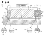
Fig. 6 is a cross-sectional view illustrating a schematic configuration of the manufacturing apparatus of the rack shaft according to a second embodiment of the invention; -
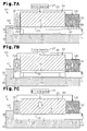
Figs. 7A to 7C are cross-sectional views illustrating each of processes when molding the rack teeth on the blank; -
Fig. 8 is a cross-sectional view illustrating a schematic configuration of a manufacturing apparatus of another example; and -
Fig. 9 is a schematic diagram illustrating the flow of the material of the machining target portion when molding the rack teeth. - Hereinafter, a first embodiment of a blank of the invention and a method of manufacturing a rack shaft using the same will be described with reference to
Figs. 1A to 5C . The rack shaft is assembled to a pinion shaft (not illustrated) which rotates by a steering operation. The rack shaft constitutes a rack-and-pinion mechanism together with a pinion shaft. - As illustrated in
Fig. 1A , therack shaft 1 has afirst shaft portion 2, asecond shaft portion 3, and ateeth portion 4. The first andsecond shaft portions first shaft portion 2 is shorter than an overall length of thesecond shaft portion 3. Theteeth portion 4 is formed between thefirst shaft portion 2 and thesecond shaft portion 3. In theteeth portion 4, a plurality ofrack teeth 5 are aligned in the axial direction of therack shaft 1. Each of therack teeth 5 is formed to continuously change a pressure angle and the like, depending on an axial position. Therack shaft 1 is adopted for a variable gear ratio steering gear. In the variable gear ratio steering gear, a ratio of a turning angle change of a turning wheel to a steering angle change of a steering wheel changes in accordance with the steering angle. - As illustrated in
Fig. 1B , theteeth portion 4 has a rear surface 6 on the opposite side to therack teeth 5. The rear surface 6 is formed to have a semicircular arc cross-section. The rear surface 6 has a constant shape over the overall length of theteeth portion 4. That is, the rear surface 6 has no irregularities over the overall length of theteeth portion 4. Therack shaft 1 is supported by arack guide 7 from the rear surface 6 as indicated by two-dot chain line inFig.1B , in the state of being assembled to the pinion shaft. - Next, manufacturing of the
rack shaft 1 will be described with reference toFig. 2 . - As illustrated in
Fig. 2 , therack shaft 1 is manufactured by forging the round rod-shaped blank 11 to mold therack teeth 5 thereto. The blank 11 has afirst shaft portion 12, asecond shaft portion 13, and amachining target portion 14. The first andsecond shaft portions second shaft portions first shaft portion 12 is substantially equal to an outer diameter of thesecond shaft portion 13. The overall length of thefirst shaft portion 12 is shorter than the overall length of thesecond shaft portion 13. - The
machining target portion 14 is formed between thefirst shaft portion 12 and thesecond shaft portion 13. Themachining target portion 14 is located at a position closer to theshaft end portion 15 of thefirst shaft portion 12 than the shaft end portion of thesecond shaft portion 13. Themachining target portion 14 is formed in a round rod shape that is thinner than the first andsecond shaft portions machining target portion 14 are formed to be thicker than an intermediate portion in the axial direction of themachining target portion 14. In other words, theintermediate portion 16 in the axial direction of themachining target portion 14 is thinner than the first andsecond shaft portions intermediate portion 16 is a circle having a constant outer diameter over the overall length of theintermediate portion 16. - At the first end portion of the
machining target portion 14 close to thefirst shaft portion 12, a first large-volume portion 17 forming a circular cross-sectional shape is formed. An outer diameter of the first large-volume portion 17 gradually increases toward thefirst shaft portion 12 from theintermediate portion 16. For this reason, the volume per unit length of the first large-volume portion 17 is greater than the volume per unit length of theintermediate portion 16. In other words, an area of the cross section perpendicular to the axis of the first large-volume portion 17 is greater than a cross-sectional area of theintermediate portion 16. Furthermore, an outer circumferential surface of the first large-volume portion 17 inclines with respect to the axis of the blank 11 by a first predetermined angle θ1 (for example, about 20°). - At the second end portion of the
machining target portion 14 close to thesecond shaft portion 13, a second large-volume portion 18 forming a circular cross-sectional shape is also formed. An outer diameter of the second large-volume portion 18 gradually increases toward thesecond shaft portion 13 from theintermediate portion 16. For this reason, the volume per unit length of the second large-volume portion 18 is greater than the volume per unit length of theintermediate portion 16. In other words, an area of the cross section perpendicular to the axis of the second large-volume portion 18 is greater than the cross-sectional area of theintermediate portion 16. Furthermore, the outer circumferential surface of the second large-volume portion 18 inclines with respect to the axis of the blank 11 by a second predetermined angle θ2 (for example, about 15°) smaller than the first predetermined angle θ1. Thus, the second large-volume portion 18 is longer than the first large-volume portion 17. Furthermore, the overall volume of the second large-volume portion 18 is greater than the overall volume of the first large-volume portion 17. Furthermore, the blank 11 is made up of a round rod having a constant outer diameter over the overall length. The blank 11 is manufactured by molding themachining target portion 14 from the round rod by forging, cutting or the like. - Next, a manufacturing apparatus of the rack shaft will be described with reference to
Fig. 3 . - As illustrated in
Fig. 3 , themanufacturing apparatus 21 is equipped with a die 22, a first punch die 24, a second punch die 25, and apunch 26. Thepunch 26 is located between the first punch die 24 and the second punch die 25. The first punch die 24, the second punch die 25, and thepunch 26 vertically move independently of each other by a drivingapparatus 27 using hydraulic pressure or the like. As a result, the first punch die 24, the second punch die 25, and thepunch 26 are close to or spaced from thedie 22. - A first gripping
portion 31 is formed by thedie 22 and the first punch die 24. The first grippingportion 31 has a cylindrical first innercircumferential surface 31 a coming into contact with thefirst shaft portion 12 of the blank 11. A second grippingportion 32 is formed by thedie 22 and the second punch die 25. The secondgripping portion 32 has a cylindrical second innercircumferential surface 32a coming into contact with thesecond shaft portion 13. Ateeth forging portion 33 is formed by thedie 22 and thepunch 26. Theteeth forging portion 33 is a portion that forges themachining target portion 14 in order to mold therack teeth 5. - The
die 22 is formed in a rectangular shape. A lowergripping groove 41 is formed on an upper surface of the die 22 facing the first punch die 24, the second punch die 25, and thepunch 26. A part of thefirst shaft portion 12, thesecond shaft portion 13, and themachining target portion 14 of the blank 11 is housed in the lowergripping groove 41. The lowergripping groove 41 extends in a straight line shape. The lowergripping groove 41 extends substantially parallel to the side edges of thedie 22. A first axial end of the lowergripping groove 41, that is, a left end illustrated inFig. 3 is not opened at the end surface of thedie 22. That is, the first end of the lowergripping groove 41 is blocked. A blockingportion 42 is formed in the die 22 to block the first end of the lowergripping groove 41. - Meanwhile, a second axial end of the lower
gripping groove 41, that is, a right end ofFig. 3 is opened at the end surface of thedie 22. As illustrated inFigs. 5A to 5C , the overall length of the lowergripping groove 41 is set to be able to house thesecond shaft portion 13 over a range longer than the overall length of thefirst shaft portion 12 in a state of bringing theshaft end portion 15 of the blank 11 into contact with the blockingportion 42. The cross-section of the lowergripping groove 41 is formed in a semicircular shape over the overall length of the lowergripping groove 41. The inner diameter of the lowergripping groove 41 is substantially equal to the outer diameters of the first andsecond shaft portions - The first punch die 24 is formed in a rectangular shape. At the lower surface facing the
die 22 of the first punch die 24, a first upper gripping groove 51 having a semicircular cross section is formed. Thefirst shaft portion 12 of the blank 11 is housed in the first upper gripping groove 51. The first upper gripping groove 51 is formed in a linear shape and extends substantially parallel to the lowergripping groove 41. The overall length of the first upper gripping groove 51 is substantially equal to the overall length of thefirst shaft portion 12 of the blank 11. Each axial end portion of the first upper gripping groove 51 is opened at the end surface corresponding to the first punch die 24. - The inner diameter of the first upper gripping groove 51 is substantially equal to the outer diameter of the
first shaft portion 12 over the overall length of the first upper gripping groove 51. When the first punch die 24 comes close to thedie 22, thefirst shaft portion 12 of the blank 11 is gripped between the first upper gripping groove 51 and the lowergripping groove 41. Thus, the first grippingportion 31 is formed by thedie 22 and the first punch die 24. Furthermore, a first innercircumferential surface 31 a coming into contact with the outer circumferential surface of thefirst shaft portion 12 is formed by an inner wall surface 41 a of the lowergripping groove 41 and an inner wall surface 51 a of the first upper gripping groove 51. - The second punch die 25 is formed in a rectangular shape. On a lower surface of the second punch die 25 facing the
die 22, a second upper grippinggroove 61 having a semicircular cross-section is formed. A part of thesecond shaft portion 13 of the blank 11 is housed in the second upper grippinggroove 61. The second upper grippinggroove 61 is formed in a linear shape and extends substantially parallel to the lowergripping groove 41. The overall length of the second upper grippinggroove 61 is longer than the overall length of the first upper gripping groove 51. Each axial end portion of the second upper grippinggroove 61 is opened at the end surface corresponding to the second punch die 25. - The inner diameter of the second upper gripping
groove 61 is substantially equal to the outer diameter of thesecond shaft portion 13 over the overall length of the second upper grippinggroove 61. When the second punch die 25 comes close to thedie 22, thesecond shaft portion 13 of the blank 11 is gripped between the second upper grippinggroove 61 and the lowergripping groove 41. Thus, the second grippingportion 32 is formed by thedie 22 and the second punch die 25. Furthermore, a second innercircumferential surface 32a coming into contact with the outer circumferential surface of thesecond shaft portion 13 is formed by the inner wall surface 41 a of the lowergripping groove 41 and theinner wall surface 61 a of the second upper grippinggroove 61. - The
punch 26 is formed in a rectangular shape. A teeth-shapedgroove 71 is formed on the lower surface of thepunch 26 facing thedie 22. The teeth-shapedgroove 71 is formed coaxially with the first and second uppergripping grooves 51 and 61. The overall length of the teeth-shapedgroove 71 is substantially equal to the overall length of themachining target portion 14 of the blank 11. Each of the axial end portions of the teeth-shapedgroove 71 is opened at the corresponding end surface of thepunch 26. A plurality ofteeth 72 are formed on the teeth-shapedgroove 71. The plurality ofteeth 72 are formed by inverting the plurality ofrack teeth 5 of therack shaft 1. As illustrated inFigs. 1B ,3 and 4 , the teeth-shapedgroove 71 defines a space having substantially the same shape as theteeth portion 4 of therack shaft 1 when bringing thepunch 26 into contact with thedie 22. Thus, ateeth forging portion 33 is formed by thedie 22 and thepunch 26. - Next, a method of manufacturing a rack shaft according to the first embodiment will be described with reference to
Figs. 5A to 5C . - As illustrated in
Fig. 5A , in order to mold therack teeth 5 on themachining target portion 14 of the blank 11, first, the blank 11 is located within the lowergripping groove 41 of thedie 22. - Next, as illustrated in
Fig. 5B , the first and second punch dies 24 and 25 are brought close to the die 22 by the drivingapparatus 27. In this way, thefirst shaft portion 12 of the blank 11 is located between the first upper gripping groove 51 and the lowergripping groove 41, and thesecond shaft portion 13 of the blank 11 is located between the second upper grippinggroove 61 and the lowergripping groove 41. Thus, thefirst shaft portion 12 is gripped by the first grippingportion 31, and thesecond shaft portion 13 is gripped by the second grippingportion 32. - Moreover, as illustrated in
Fig. 5C , thepunch 26 is brought close to the die 22 by the drivingapparatus 27 from the state illustrated inFig. 5B . In this way, themachining target portion 14 of the blank 11 is forged by theteeth forging portion 33. Specifically, theteeth forging portion 33 plastically deforms themachining target portion 14 to fill the blocked space of substantially the same shape as theteeth portion 4 of therack shaft 1. As a result, the plurality ofrack teeth 5 is formed on themachining target portion 14 of the blank 11. - At this time, a part of the material of the
machining target portion 14 flows into each of the first andsecond shaft portions machining target portion 14 is formed at a position closer to theshaft end portion 15 of thefirst shaft portion 12 than the shaft end portion of thesecond shaft portion 13. For this reason, the material of themachining target portion 14 easily flows into thesecond shaft portion 13. - In this regard, in the first embodiment, the volumes per unit length of the first and second large-
volume portions machining target portion 14 are greater than the volume per unit length of theintermediate portion 16. Furthermore, the volume of the second large-volume portion 18 is greater than the volume of the first large-volume portion 17. For this reason, when forging themachining target portion 14, even if the material of the first large-volume portion 17 flows into thefirst shaft portion 12 and more material of the second large-volume portion 18 flows into thesecond shaft portion 13, since the volume of the second large-volume portion 18 is greater than the volume of the first large-volume portion 17, the material shortage in the first and second large-volume portions - Therefore, according to the first embodiment, it is possible to obtain the following effects.
- (1) The volumes per unit length of the first and second large-
volume portions intermediate portion 16. For this reason, when forging themachining target portion 14, the material shortage in the first and second large-volume portions volume portions teeth forging portion 33 is not lowered. Therefore, in the first and second large-volume portions teeth 72. Therefore, the shape accuracy of therack teeth 5 is improved. - (2) The
machining target portion 14 of the blank 11 is formed at a position closer to theshaft end portion 15 of thefirst shaft portion 12 than the shaft end portion of thesecond shaft portion 13. In this type of the blank 11, the overall length of thesecond shaft portion 13 is longer than the overall length of thefirst shaft portion 12, and the overall volume of thesecond shaft portion 13 is greater than the overall volume of thefirst shaft portion 12. For this reason, when forging themachining target portion 14, at the second end portion of themachining target portion 14 close to thesecond shaft portion 13, since the material easily flows into thesecond shaft portion 13, the material is likely to become insufficient. In this respect, according to the first embodiment, the second large-volume portion 18 is greater than the volume of the first large-volume portion 17. For this reason, even in the blank 11 in which themachining target portion 14 is formed at a position close to thefirst shaft portion 12, the material shortage in the second large-volume portion 18 is suppressed. - (3) The first and second large-
volume portions machining target portion 14 close to the first andsecond shaft portions machining target portion 14. - Hereinafter, a second embodiment of the invention will be described with reference to
Figs. 6 to 7C . In addition, the detailed description of the portions in the second embodiment similar to those of the first embodiment will not be provided. - As illustrated in
Fig. 6 , on theinner wall surface 141 a of the lowergripping groove 141, a plurality ofridges 143 as a friction increasing structure are formed. Theridges 143 are formed in a range in which thefirst shaft portion 12 of the blank 11 is located, that is, a range facing thefirst punch die 124. Furthermore, on theinner wall surface 141 a of the lowergripping groove 141, a plurality ofridges 144 as a friction increasing structure are formed. Theridges 144 are formed in a range in which thesecond shaft portion 13 of the blank 11 is located, that is, a range facing the second punch die 125. - The
ridges gripping groove 141, respectively. Moreover, theridges gripping groove 141. A range in which themachining target portion 14 of the blank 11 is located on theinner wall surface 141 a of the lowergripping groove 141 is an opposing surface of thepunch 26 facing theteeth 72. A portion of theinner wall surface 141 a facing theteeth 72 has no irregularities over the overall length of the portion. - A plurality of
ridges 152 as a friction increasing structure are also formed on theinner wall surface 151 a of the first uppergripping groove 151. Theridges 152 protrude radially inward from the wall surface of the first uppergripping groove 151. Furthermore, theridges 152 are formed in a semicircular arc shape and extend in the circumferential direction of the first uppergripping groove 151. Each of the plurality of theridges 152 is formed at a position facing the correspondingridges 143. For this reason, annular ridges coming into contact with the entire circumference of thefirst shaft portion 12 of the blank 11 are formed by theridges - On the
inner wall surface 161 a of the second upper grippinggroove 161, a plurality ofridges 162 as a friction increasing structure are formed. Theridges 162 protrude radially inward from the wall surface of the second upper grippinggroove 161. Furthermore, theridges 162 are formed in a semicircular arc shape and extend in the circumferential direction of the second upper grippinggroove 161. Each of the plurality of theridges 162 is formed at a position facing the correspondingridges 144. For this reason, annular ridges coming into contact with the entire circumference of thesecond shaft portion 13 of the blank 11 are formed by theridges 162 and theridges 144. - In addition, the overall length of the second upper gripping
groove 161 is longer than the overall length of the first uppergripping groove 151. For this reason, an axial length L2 of the second innercircumferential surface 132a is greater than an axial length L1 of the first innercircumferential surface 131 a. - Next, a method of manufacturing the rack shaft according to a second embodiment will be described with reference to
Figs. 7A to 7C . - As illustrated in
Fig. 7A , in order to mold therack teeth 5 on themachining target portion 14 of the blank 11, first, the blank 11 is located within the lowergripping groove 141 of thedie 122. - Next, as illustrated in
Fig. 7B , the first and second punch dies 124 and 125 are brought close to the die 122 by the drivingapparatus 27. In this way, thefirst shaft portion 12 of the blank 11 is located between the first uppergripping groove 151 and the lowergripping groove 141, and thesecond shaft portion 13 of the blank 11 is located between the second upper grippinggroove 161 and the lowergripping groove 141. Thus, thefirst shaft portion 12 is gripped by the firstgripping portion 131, and thesecond shaft portion 13 is gripped by the secondgripping portion 132. - As described above, in the second embodiment, the
ridges circumferential surface 131 a of the firstgripping portion 131 coming into contact with thefirst shaft portion 12. For this reason, the material of thefirst shaft portion 12 is caught by theridges first shaft portion 12 is increased by theridges machining target portion 14, the flow of the material into thefirst shaft portion 12 from themachining target portion 14 is limited. Thus, the material shortage at the first end portion of themachining target portion 14 close to thefirst shaft portion 12 is suppressed. - Similarly,
ridges circumferential surface 132a of the secondgripping portion 132 coming into contact with thesecond shaft portion 13. For this reason, the material of thesecond shaft portion 13 is caught by theridges second shaft portion 13 is increased by theridges gripping portion 132 is longer than the axial length L1 of the firstgripping portion 131, restraining force is applied over a wide range of thesecond shaft portion 13 from the secondgripping portion 132. That is, when forging themachining target portion 14, a region having a high internal pressure occurs over a wide range of thesecond shaft portion 13. As a result, the flow of the material into thesecond shaft portion 13 from themachining target portion 14 is limited. Thus, the material shortage at the second end portion of themachining target portion 14 close to thesecond shaft portion 13 is suppressed. - Therefore, according to the second embodiment, it is possible to obtain the following effects.
- (4) The
ridges circumferential surface 131 a of the firstgripping portion 131. Furthermore, theridges circumferential surface 132a of the secondgripping portion 132. By such a friction increasing structure, the flow of the material into each of the first andsecond shaft portions machining target portion 14 is limited. Thus, the material shortage at both end portions of themachining target portion 14 close to the first andsecond shaft portions machining target portion 14, at both end portions of themachining target portion 14 close to the first andsecond shaft portions teeth forging portion 33 is suppressed. As a result, at both end portions of themachining target portion 14 close to the first andsecond shaft portions teeth 72. Therefore, the shape accuracy of therack teeth 5 is improved. - (5) The
machining target portion 14 of the blank 11 is formed at a position closer to theshaft end portion 15 of thefirst shaft portion 12 than the shaft end portion of thesecond shaft portion 13. In this type of the blank 11, the overall length of thesecond shaft portion 13 is longer than the overall length of thefirst shaft portion 12, and the overall volume of thesecond shaft portion 13 is greater than the overall volume of thefirst shaft portion 12. For this reason, when forging themachining target portion 14, at the second end portion of themachining target portion 14 close to thesecond shaft portion 13, since the material easily flows into thesecond shaft portion 13, the material is likely to become insufficient. In this respect, according to the second embodiment, the axial length L2 of the secondgripping portion 132 is longer than the axial length L1 of the firstgripping portion 131. In this case, since a region having a high internal pressure occurs over a wide range of thesecond shaft portion 13, the flow of the material into thesecond shaft portion 13 from themachining target portion 14 is limited. Thus, the material shortage at the second end portion of themachining target portion 14 close to thesecond shaft portion 13 is suppressed. - (6) A portion facing the
teeth 72 on theinner wall surface 141 a of the lowergripping groove 141 has no irregularities over the overall length of the portion. For this reason, when molding therack teeth 5 on themachining target portion 14, the rear surface 6 of themachining target portion 14 located on the opposite side to therack teeth 5 is finished to a smooth surface shape having no irregularities. For that reason, even if machining is hardly performed after forging themachining target portion 14, it is possible to finish therack shaft 1 to a final shape. In this way, it is possible to mold therack shaft 1 supported to be movable back and forth with respect to therack guide 7. - (7) Any of the
ridges gripping groove 141, the first uppergripping groove 151, and the second upper grippinggroove 161. It is possible to increase the frictional resistance when the materials of the first andsecond shaft portions - In addition, the first and second embodiments may be modified as follows.
- In the first embodiment, the cross-sectional shape of the
machining target portion 14 may be changed to an elliptical shape or a shape in which two parallel surfaces are formed by cutting a part of a circle. - The first and second large-
volume portions volume portions - The
machining target portion 14 may be formed so that the volume of the second large-volume portion 18 is equal to the volume of the first large-volume portion 17 or smaller than the volume of the first large-volume portion 17. - The
machining target portion 14 may be formed so that only one volume per unit length of both end portions of themachining target portion 14 close to the first andsecond shaft portions intermediate portion 16. - In the second embodiment, the
ridges circumferential surfaces - As illustrated in
Fig. 8 , on the first and second innercircumferential surfaces convex portions convex portions 181 to 184. - The
ridges circumferential surface 131 a, and theridges circumferential surface 132a. Similarly, theridges circumferential surface 131 a, and theridges circumferential surface 132a. Furthermore, the ridge may not be formed on the entire circumference of the first innercircumferential surface 131 a. For example, theridges 143 may be formed only on theinner wall surface 141 a of the lowergripping groove 141, or theridges 152 may be formed only on theinner wall surface 151 a of the first uppergripping groove 151. Similarly, theridges 144 may be formed only on theinner wall surface 141 a of the lowergripping groove 141, or theridges 162 may be formed only on theinner wall surface 161 a of the second upper grippinggroove 161. - The
ridges circumferential surfaces circumferential surface 132a longer than the axial length L1 of the first innercircumferential surface 131 a, the material shortage at both end portions of themachining target portion 14 close to the first andsecond shaft portions - The axial length L1 of the first inner
circumferential surface 131 a may be substantially equal to the axial length L2 of the second innercircumferential surface 132a. - The irregularities may be provided in the portion facing the
teeth 72 at theinner wall surface 141 a of the lowergripping groove 141. - The blank 11 in which both axial end portions of the
machining target portion 14 are thicker than the center thereof was used, but a blank of a round bar in which themachining target portion 14 is constant over the overall length may be used. - Instead of the
rack shaft 1 of a variable gear ratio type, in manufacturing of the rack shaft in which a ratio of the turning angle change of the turning wheel to the steering angle change of the steering wheel is constant regardless of the steering angle, the first or the second embodiment may be applied.
Claims (5)
- A blank that is equipped with a first shaft portion, a second shaft portion, a machining target portion, which is provided between the first shaft portion and the second shaft portion, and a plurality of rack teeth, which are aligned in an axial direction and molded on the machining target portion, the blank being characterized in that
a volume per unit length of at least one of a first end portion of the machining target portion, which is close to the first shaft portion, and a second end portion of the machining target portion, which is close to the second shaft portion, is greater than a volume per unit length of an intermediate portion in the axial direction of the machining target portion. - The blank according to claim 1, being characterized in that
the machining target portion is formed at a position closer to a shaft end portion of the first shaft portion than a shaft end portion of the second shaft portion,
a first large-volume portion is formed at the first end portion of the machining target portion,
a second large-volume portion is formed at the second end portion of the machining target portion, and
the second large-volume portion has a larger volume than the first large-volume portion. - The blank according to claim 2, being characterized in that the first and second large-volume portions are formed in a tapered shape, respectively.
- A method of manufacturing a rack shaft being characterized by:providing a blank that is equipped with a first shaft portion, a second shaft portion, and a machining target portion, which is located between the first shaft portion and the second shaft portion, wherein a volume per unit length of at least one of a first end portion of the machining target portion, which is close to the first shaft portion, and a second end portion of the machining target portion, which is close to the second shaft portion, is greater than a volume per unit length of an intermediate portion in the axial direction of the machining target portion; andmolding a plurality of rack teeth, which are aligned in an axial direction of the blank, on the machining target portion by forging the machining target portion while gripping the first and second shaft portions.
- The method of manufacturing the rack shaft according to claim 4, being characterized in that
in the molding of the plurality of rack teeth, the machining target portion is plastically deformed to fill a closed space of substantially the same shape as a teeth portion of the rack shaft formed with the rack teeth.
Applications Claiming Priority (2)
| Application Number | Priority Date | Filing Date | Title |
|---|---|---|---|
| JP2013138153A JP6175940B2 (en) | 2013-07-01 | 2013-07-01 | Rack shaft manufacturing method |
| JP2013138152A JP6160306B2 (en) | 2013-07-01 | 2013-07-01 | Rack shaft manufacturing apparatus and manufacturing method |
Publications (2)
| Publication Number | Publication Date |
|---|---|
| EP2821317A1 true EP2821317A1 (en) | 2015-01-07 |
| EP2821317B1 EP2821317B1 (en) | 2017-11-15 |
Family
ID=50979548
Family Applications (1)
| Application Number | Title | Priority Date | Filing Date |
|---|---|---|---|
| EP14172513.5A Not-in-force EP2821317B1 (en) | 2013-07-01 | 2014-06-16 | Method of manufacturing a rack shaft |
Country Status (3)
| Country | Link |
|---|---|
| US (1) | US9492897B2 (en) |
| EP (1) | EP2821317B1 (en) |
| CN (1) | CN104279301B (en) |
Families Citing this family (4)
| Publication number | Priority date | Publication date | Assignee | Title |
|---|---|---|---|---|
| JP5957309B2 (en) * | 2012-06-21 | 2016-07-27 | 高周波熱錬株式会社 | Rack bar and rack bar forming teeth |
| JP6202109B2 (en) * | 2014-01-22 | 2017-09-27 | 日本精工株式会社 | Steering rack, steering apparatus, automobile, steering rack manufacturing method, steering apparatus manufacturing method, and automobile manufacturing method |
| CN108500140A (en) * | 2018-03-26 | 2018-09-07 | 太仓久信精密模具股份有限公司 | A kind of shaping dies and method of pitches rack performing member |
| US11027767B2 (en) * | 2018-11-30 | 2021-06-08 | Steering Solutions Ip Holding Corporation | Steering system rack with stepped portion |
Citations (5)
| Publication number | Priority date | Publication date | Assignee | Title |
|---|---|---|---|---|
| DE10149989A1 (en) * | 2001-10-11 | 2003-04-17 | Hmp Engineering Gmbh | Preform for producing rack has at least two conical sectors, narrow ends of which are facing each other |
| WO2005053875A1 (en) * | 2003-12-04 | 2005-06-16 | Bishop Innovation Limited | Steering rack manufacture |
| WO2006037167A1 (en) * | 2004-10-07 | 2006-04-13 | Bishop Innovation Limited | Steering rack |
| US20080184833A1 (en) * | 2005-03-23 | 2008-08-07 | Juergen Dohmann | Steering Rack and Method of Manufacture Thereof |
| US20120137747A1 (en) * | 2009-08-12 | 2012-06-07 | Wayne Bruce Cornish | Forging die apparatus for steering racks |
Family Cites Families (2)
| Publication number | Priority date | Publication date | Assignee | Title |
|---|---|---|---|---|
| WO2008053896A1 (en) * | 2006-11-02 | 2008-05-08 | Nsk Ltd. | Rack and production method thereof |
| US8365573B2 (en) * | 2007-02-23 | 2013-02-05 | Neutron Co., Ltd. | Mandrel, set of mandrels, and hollow rack bar |
-
2014
- 2014-06-09 US US14/299,494 patent/US9492897B2/en not_active Expired - Fee Related
- 2014-06-16 EP EP14172513.5A patent/EP2821317B1/en not_active Not-in-force
- 2014-06-18 CN CN201410273397.1A patent/CN104279301B/en not_active Expired - Fee Related
Patent Citations (6)
| Publication number | Priority date | Publication date | Assignee | Title |
|---|---|---|---|---|
| DE10149989A1 (en) * | 2001-10-11 | 2003-04-17 | Hmp Engineering Gmbh | Preform for producing rack has at least two conical sectors, narrow ends of which are facing each other |
| WO2005053875A1 (en) * | 2003-12-04 | 2005-06-16 | Bishop Innovation Limited | Steering rack manufacture |
| WO2006037167A1 (en) * | 2004-10-07 | 2006-04-13 | Bishop Innovation Limited | Steering rack |
| US20080184833A1 (en) * | 2005-03-23 | 2008-08-07 | Juergen Dohmann | Steering Rack and Method of Manufacture Thereof |
| US20120137747A1 (en) * | 2009-08-12 | 2012-06-07 | Wayne Bruce Cornish | Forging die apparatus for steering racks |
| JP2013501621A (en) | 2009-08-12 | 2013-01-17 | ビショップ ステアリング テクノロジー ピーティーワイ リミテッド | Forging mold equipment for steering rack |
Also Published As
| Publication number | Publication date |
|---|---|
| CN104279301B (en) | 2018-04-06 |
| CN104279301A (en) | 2015-01-14 |
| US20150000135A1 (en) | 2015-01-01 |
| US9492897B2 (en) | 2016-11-15 |
| EP2821317B1 (en) | 2017-11-15 |
Similar Documents
| Publication | Publication Date | Title |
|---|---|---|
| US9492897B2 (en) | Blank and method of manufacturing rack shaft using the same | |
| EP2690262A1 (en) | Method for manufacturing hollow engine valve | |
| EP3343069B1 (en) | Steering rack and manufacturing method therefor | |
| US11614156B2 (en) | Metal sleeve and method for producing it | |
| JP2002172430A (en) | Method and apparatus for manufacturing cylindrical member and cylindrical member having spline | |
| WO2014185357A1 (en) | Press molding method for cup-shaped member | |
| RU2715511C1 (en) | Method for production of rhomboid retaining flight on outer surface of shell | |
| JP2018083215A (en) | Manufacturing method of metallic member | |
| JP2019072769A (en) | Rack and method for manufacturing the same, steering apparatus, vehicle, and mold for preforming rack | |
| KR20170046450A (en) | Cold forging device for manufacturing parking gear | |
| US4347636A (en) | Nut and method of forming the same | |
| EP2149412B1 (en) | Horizontal-press cold-forging machine with reduced-speed hammering | |
| US10857582B2 (en) | Method of manufacturing tooth-shaped component, and tooth-shaped component | |
| JP6175940B2 (en) | Rack shaft manufacturing method | |
| JPS63120958A (en) | Speed change gear and manufacture thereof | |
| JP5040686B2 (en) | Die for forging and processing method thereof, gear forging device and gear forging method | |
| EP2952273A1 (en) | Forging device and forging method | |
| JP6160306B2 (en) | Rack shaft manufacturing apparatus and manufacturing method | |
| JP5134361B2 (en) | 2-stage helical gear | |
| JP7178687B2 (en) | Helical gear and method for manufacturing helical gear | |
| RU2612857C1 (en) | Tool for planetary thread rolling with axial oscillation of moulding surface | |
| JP6347770B2 (en) | Mold for spline processing | |
| RU146515U1 (en) | STAMP FOR OPEN VOLUME STAMPING OF FORGING | |
| JP2019118944A (en) | Manufacturing method of different-diameter pipe | |
| SU1324832A1 (en) | Method of machining splined holes |
Legal Events
| Date | Code | Title | Description |
|---|---|---|---|
| PUAI | Public reference made under article 153(3) epc to a published international application that has entered the european phase |
Free format text: ORIGINAL CODE: 0009012 |
|
| 17P | Request for examination filed |
Effective date: 20140616 |
|
| AK | Designated contracting states |
Kind code of ref document: A1 Designated state(s): AL AT BE BG CH CY CZ DE DK EE ES FI FR GB GR HR HU IE IS IT LI LT LU LV MC MK MT NL NO PL PT RO RS SE SI SK SM TR |
|
| AX | Request for extension of the european patent |
Extension state: BA ME |
|
| R17P | Request for examination filed (corrected) |
Effective date: 20150706 |
|
| RBV | Designated contracting states (corrected) |
Designated state(s): AL AT BE BG CH CY CZ DE DK EE ES FI FR GB GR HR HU IE IS IT LI LT LU LV MC MK MT NL NO PL PT RO RS SE SI SK SM TR |
|
| 17Q | First examination report despatched |
Effective date: 20151130 |
|
| GRAP | Despatch of communication of intention to grant a patent |
Free format text: ORIGINAL CODE: EPIDOSNIGR1 |
|
| INTG | Intention to grant announced |
Effective date: 20170515 |
|
| GRAS | Grant fee paid |
Free format text: ORIGINAL CODE: EPIDOSNIGR3 |
|
| GRAA | (expected) grant |
Free format text: ORIGINAL CODE: 0009210 |
|
| RIN1 | Information on inventor provided before grant (corrected) |
Inventor name: OUMI, HIROYUKI |
|
| RAP1 | Party data changed (applicant data changed or rights of an application transferred) |
Owner name: JTEKT CORPORATION |
|
| AK | Designated contracting states |
Kind code of ref document: B1 Designated state(s): AL AT BE BG CH CY CZ DE DK EE ES FI FR GB GR HR HU IE IS IT LI LT LU LV MC MK MT NL NO PL PT RO RS SE SI SK SM TR |
|
| REG | Reference to a national code |
Ref country code: CH Ref legal event code: EP Ref country code: GB Ref legal event code: FG4D Ref country code: AT Ref legal event code: REF Ref document number: 945960 Country of ref document: AT Kind code of ref document: T Effective date: 20171115 |
|
| REG | Reference to a national code |
Ref country code: IE Ref legal event code: FG4D |
|
| REG | Reference to a national code |
Ref country code: DE Ref legal event code: R096 Ref document number: 602014017136 Country of ref document: DE |
|
| REG | Reference to a national code |
Ref country code: NL Ref legal event code: MP Effective date: 20171115 |
|
| REG | Reference to a national code |
Ref country code: LT Ref legal event code: MG4D |
|
| REG | Reference to a national code |
Ref country code: AT Ref legal event code: MK05 Ref document number: 945960 Country of ref document: AT Kind code of ref document: T Effective date: 20171115 |
|
| PG25 | Lapsed in a contracting state [announced via postgrant information from national office to epo] |
Ref country code: ES Free format text: LAPSE BECAUSE OF FAILURE TO SUBMIT A TRANSLATION OF THE DESCRIPTION OR TO PAY THE FEE WITHIN THE PRESCRIBED TIME-LIMIT Effective date: 20171115 Ref country code: NO Free format text: LAPSE BECAUSE OF FAILURE TO SUBMIT A TRANSLATION OF THE DESCRIPTION OR TO PAY THE FEE WITHIN THE PRESCRIBED TIME-LIMIT Effective date: 20180215 Ref country code: FI Free format text: LAPSE BECAUSE OF FAILURE TO SUBMIT A TRANSLATION OF THE DESCRIPTION OR TO PAY THE FEE WITHIN THE PRESCRIBED TIME-LIMIT Effective date: 20171115 Ref country code: SE Free format text: LAPSE BECAUSE OF FAILURE TO SUBMIT A TRANSLATION OF THE DESCRIPTION OR TO PAY THE FEE WITHIN THE PRESCRIBED TIME-LIMIT Effective date: 20171115 Ref country code: LT Free format text: LAPSE BECAUSE OF FAILURE TO SUBMIT A TRANSLATION OF THE DESCRIPTION OR TO PAY THE FEE WITHIN THE PRESCRIBED TIME-LIMIT Effective date: 20171115 Ref country code: NL Free format text: LAPSE BECAUSE OF FAILURE TO SUBMIT A TRANSLATION OF THE DESCRIPTION OR TO PAY THE FEE WITHIN THE PRESCRIBED TIME-LIMIT Effective date: 20171115 |
|
| REG | Reference to a national code |
Ref country code: FR Ref legal event code: PLFP Year of fee payment: 5 |
|
| PG25 | Lapsed in a contracting state [announced via postgrant information from national office to epo] |
Ref country code: AT Free format text: LAPSE BECAUSE OF FAILURE TO SUBMIT A TRANSLATION OF THE DESCRIPTION OR TO PAY THE FEE WITHIN THE PRESCRIBED TIME-LIMIT Effective date: 20171115 Ref country code: GR Free format text: LAPSE BECAUSE OF FAILURE TO SUBMIT A TRANSLATION OF THE DESCRIPTION OR TO PAY THE FEE WITHIN THE PRESCRIBED TIME-LIMIT Effective date: 20180216 Ref country code: LV Free format text: LAPSE BECAUSE OF FAILURE TO SUBMIT A TRANSLATION OF THE DESCRIPTION OR TO PAY THE FEE WITHIN THE PRESCRIBED TIME-LIMIT Effective date: 20171115 Ref country code: BG Free format text: LAPSE BECAUSE OF FAILURE TO SUBMIT A TRANSLATION OF THE DESCRIPTION OR TO PAY THE FEE WITHIN THE PRESCRIBED TIME-LIMIT Effective date: 20180215 Ref country code: HR Free format text: LAPSE BECAUSE OF FAILURE TO SUBMIT A TRANSLATION OF THE DESCRIPTION OR TO PAY THE FEE WITHIN THE PRESCRIBED TIME-LIMIT Effective date: 20171115 Ref country code: RS Free format text: LAPSE BECAUSE OF FAILURE TO SUBMIT A TRANSLATION OF THE DESCRIPTION OR TO PAY THE FEE WITHIN THE PRESCRIBED TIME-LIMIT Effective date: 20171115 |
|
| PG25 | Lapsed in a contracting state [announced via postgrant information from national office to epo] |
Ref country code: SK Free format text: LAPSE BECAUSE OF FAILURE TO SUBMIT A TRANSLATION OF THE DESCRIPTION OR TO PAY THE FEE WITHIN THE PRESCRIBED TIME-LIMIT Effective date: 20171115 Ref country code: DK Free format text: LAPSE BECAUSE OF FAILURE TO SUBMIT A TRANSLATION OF THE DESCRIPTION OR TO PAY THE FEE WITHIN THE PRESCRIBED TIME-LIMIT Effective date: 20171115 Ref country code: CY Free format text: LAPSE BECAUSE OF FAILURE TO SUBMIT A TRANSLATION OF THE DESCRIPTION OR TO PAY THE FEE WITHIN THE PRESCRIBED TIME-LIMIT Effective date: 20171115 Ref country code: EE Free format text: LAPSE BECAUSE OF FAILURE TO SUBMIT A TRANSLATION OF THE DESCRIPTION OR TO PAY THE FEE WITHIN THE PRESCRIBED TIME-LIMIT Effective date: 20171115 Ref country code: CZ Free format text: LAPSE BECAUSE OF FAILURE TO SUBMIT A TRANSLATION OF THE DESCRIPTION OR TO PAY THE FEE WITHIN THE PRESCRIBED TIME-LIMIT Effective date: 20171115 |
|
| REG | Reference to a national code |
Ref country code: DE Ref legal event code: R097 Ref document number: 602014017136 Country of ref document: DE |
|
| PG25 | Lapsed in a contracting state [announced via postgrant information from national office to epo] |
Ref country code: IT Free format text: LAPSE BECAUSE OF FAILURE TO SUBMIT A TRANSLATION OF THE DESCRIPTION OR TO PAY THE FEE WITHIN THE PRESCRIBED TIME-LIMIT Effective date: 20171115 Ref country code: PL Free format text: LAPSE BECAUSE OF FAILURE TO SUBMIT A TRANSLATION OF THE DESCRIPTION OR TO PAY THE FEE WITHIN THE PRESCRIBED TIME-LIMIT Effective date: 20171115 Ref country code: SM Free format text: LAPSE BECAUSE OF FAILURE TO SUBMIT A TRANSLATION OF THE DESCRIPTION OR TO PAY THE FEE WITHIN THE PRESCRIBED TIME-LIMIT Effective date: 20171115 Ref country code: RO Free format text: LAPSE BECAUSE OF FAILURE TO SUBMIT A TRANSLATION OF THE DESCRIPTION OR TO PAY THE FEE WITHIN THE PRESCRIBED TIME-LIMIT Effective date: 20171115 |
|
| PLBE | No opposition filed within time limit |
Free format text: ORIGINAL CODE: 0009261 |
|
| STAA | Information on the status of an ep patent application or granted ep patent |
Free format text: STATUS: NO OPPOSITION FILED WITHIN TIME LIMIT |
|
| 26N | No opposition filed |
Effective date: 20180817 |
|
| PG25 | Lapsed in a contracting state [announced via postgrant information from national office to epo] |
Ref country code: SI Free format text: LAPSE BECAUSE OF FAILURE TO SUBMIT A TRANSLATION OF THE DESCRIPTION OR TO PAY THE FEE WITHIN THE PRESCRIBED TIME-LIMIT Effective date: 20171115 |
|
| REG | Reference to a national code |
Ref country code: CH Ref legal event code: PL |
|
| GBPC | Gb: european patent ceased through non-payment of renewal fee |
Effective date: 20180616 |
|
| REG | Reference to a national code |
Ref country code: BE Ref legal event code: MM Effective date: 20180630 |
|
| REG | Reference to a national code |
Ref country code: IE Ref legal event code: MM4A |
|
| PG25 | Lapsed in a contracting state [announced via postgrant information from national office to epo] |
Ref country code: MC Free format text: LAPSE BECAUSE OF FAILURE TO SUBMIT A TRANSLATION OF THE DESCRIPTION OR TO PAY THE FEE WITHIN THE PRESCRIBED TIME-LIMIT Effective date: 20171115 Ref country code: LU Free format text: LAPSE BECAUSE OF NON-PAYMENT OF DUE FEES Effective date: 20180616 |
|
| PG25 | Lapsed in a contracting state [announced via postgrant information from national office to epo] |
Ref country code: CH Free format text: LAPSE BECAUSE OF NON-PAYMENT OF DUE FEES Effective date: 20180630 Ref country code: LI Free format text: LAPSE BECAUSE OF NON-PAYMENT OF DUE FEES Effective date: 20180630 Ref country code: IE Free format text: LAPSE BECAUSE OF NON-PAYMENT OF DUE FEES Effective date: 20180616 Ref country code: GB Free format text: LAPSE BECAUSE OF NON-PAYMENT OF DUE FEES Effective date: 20180616 |
|
| PG25 | Lapsed in a contracting state [announced via postgrant information from national office to epo] |
Ref country code: BE Free format text: LAPSE BECAUSE OF NON-PAYMENT OF DUE FEES Effective date: 20180630 |
|
| PG25 | Lapsed in a contracting state [announced via postgrant information from national office to epo] |
Ref country code: MT Free format text: LAPSE BECAUSE OF NON-PAYMENT OF DUE FEES Effective date: 20180616 |
|
| PG25 | Lapsed in a contracting state [announced via postgrant information from national office to epo] |
Ref country code: TR Free format text: LAPSE BECAUSE OF FAILURE TO SUBMIT A TRANSLATION OF THE DESCRIPTION OR TO PAY THE FEE WITHIN THE PRESCRIBED TIME-LIMIT Effective date: 20171115 |
|
| PG25 | Lapsed in a contracting state [announced via postgrant information from national office to epo] |
Ref country code: PT Free format text: LAPSE BECAUSE OF FAILURE TO SUBMIT A TRANSLATION OF THE DESCRIPTION OR TO PAY THE FEE WITHIN THE PRESCRIBED TIME-LIMIT Effective date: 20171115 Ref country code: HU Free format text: LAPSE BECAUSE OF FAILURE TO SUBMIT A TRANSLATION OF THE DESCRIPTION OR TO PAY THE FEE WITHIN THE PRESCRIBED TIME-LIMIT; INVALID AB INITIO Effective date: 20140616 |
|
| PG25 | Lapsed in a contracting state [announced via postgrant information from national office to epo] |
Ref country code: MK Free format text: LAPSE BECAUSE OF NON-PAYMENT OF DUE FEES Effective date: 20171115 |
|
| PG25 | Lapsed in a contracting state [announced via postgrant information from national office to epo] |
Ref country code: AL Free format text: LAPSE BECAUSE OF FAILURE TO SUBMIT A TRANSLATION OF THE DESCRIPTION OR TO PAY THE FEE WITHIN THE PRESCRIBED TIME-LIMIT Effective date: 20171115 Ref country code: IS Free format text: LAPSE BECAUSE OF FAILURE TO SUBMIT A TRANSLATION OF THE DESCRIPTION OR TO PAY THE FEE WITHIN THE PRESCRIBED TIME-LIMIT Effective date: 20180315 |
|
| PGFP | Annual fee paid to national office [announced via postgrant information from national office to epo] |
Ref country code: DE Payment date: 20210518 Year of fee payment: 8 Ref country code: FR Payment date: 20210513 Year of fee payment: 8 |
|
| REG | Reference to a national code |
Ref country code: DE Ref legal event code: R119 Ref document number: 602014017136 Country of ref document: DE |
|
| PG25 | Lapsed in a contracting state [announced via postgrant information from national office to epo] |
Ref country code: FR Free format text: LAPSE BECAUSE OF NON-PAYMENT OF DUE FEES Effective date: 20220630 |
|
| PG25 | Lapsed in a contracting state [announced via postgrant information from national office to epo] |
Ref country code: DE Free format text: LAPSE BECAUSE OF NON-PAYMENT OF DUE FEES Effective date: 20230103 |