EP2821306A1 - Control device for hybrid vehicle - Google Patents
Control device for hybrid vehicle Download PDFInfo
- Publication number
- EP2821306A1 EP2821306A1 EP12870055.6A EP12870055A EP2821306A1 EP 2821306 A1 EP2821306 A1 EP 2821306A1 EP 12870055 A EP12870055 A EP 12870055A EP 2821306 A1 EP2821306 A1 EP 2821306A1
- Authority
- EP
- European Patent Office
- Prior art keywords
- traveling mode
- vehicle
- control apparatus
- transmission
- engine
- Prior art date
- Legal status (The legal status is an assumption and is not a legal conclusion. Google has not performed a legal analysis and makes no representation as to the accuracy of the status listed.)
- Granted
Links
Images



Classifications
-
- B—PERFORMING OPERATIONS; TRANSPORTING
- B60—VEHICLES IN GENERAL
- B60K—ARRANGEMENT OR MOUNTING OF PROPULSION UNITS OR OF TRANSMISSIONS IN VEHICLES; ARRANGEMENT OR MOUNTING OF PLURAL DIVERSE PRIME-MOVERS IN VEHICLES; AUXILIARY DRIVES FOR VEHICLES; INSTRUMENTATION OR DASHBOARDS FOR VEHICLES; ARRANGEMENTS IN CONNECTION WITH COOLING, AIR INTAKE, GAS EXHAUST OR FUEL SUPPLY OF PROPULSION UNITS IN VEHICLES
- B60K6/00—Arrangement or mounting of plural diverse prime-movers for mutual or common propulsion, e.g. hybrid propulsion systems comprising electric motors and internal combustion engines
- B60K6/20—Arrangement or mounting of plural diverse prime-movers for mutual or common propulsion, e.g. hybrid propulsion systems comprising electric motors and internal combustion engines the prime-movers consisting of electric motors and internal combustion engines, e.g. HEVs
- B60K6/42—Arrangement or mounting of plural diverse prime-movers for mutual or common propulsion, e.g. hybrid propulsion systems comprising electric motors and internal combustion engines the prime-movers consisting of electric motors and internal combustion engines, e.g. HEVs characterised by the architecture of the hybrid electric vehicle
- B60K6/48—Parallel type
-
- B—PERFORMING OPERATIONS; TRANSPORTING
- B60—VEHICLES IN GENERAL
- B60K—ARRANGEMENT OR MOUNTING OF PROPULSION UNITS OR OF TRANSMISSIONS IN VEHICLES; ARRANGEMENT OR MOUNTING OF PLURAL DIVERSE PRIME-MOVERS IN VEHICLES; AUXILIARY DRIVES FOR VEHICLES; INSTRUMENTATION OR DASHBOARDS FOR VEHICLES; ARRANGEMENTS IN CONNECTION WITH COOLING, AIR INTAKE, GAS EXHAUST OR FUEL SUPPLY OF PROPULSION UNITS IN VEHICLES
- B60K6/00—Arrangement or mounting of plural diverse prime-movers for mutual or common propulsion, e.g. hybrid propulsion systems comprising electric motors and internal combustion engines
- B60K6/20—Arrangement or mounting of plural diverse prime-movers for mutual or common propulsion, e.g. hybrid propulsion systems comprising electric motors and internal combustion engines the prime-movers consisting of electric motors and internal combustion engines, e.g. HEVs
- B60K6/50—Architecture of the driveline characterised by arrangement or kind of transmission units
- B60K6/54—Transmission for changing ratio
- B60K6/547—Transmission for changing ratio the transmission being a stepped gearing
-
- B—PERFORMING OPERATIONS; TRANSPORTING
- B60—VEHICLES IN GENERAL
- B60W—CONJOINT CONTROL OF VEHICLE SUB-UNITS OF DIFFERENT TYPE OR DIFFERENT FUNCTION; CONTROL SYSTEMS SPECIALLY ADAPTED FOR HYBRID VEHICLES; ROAD VEHICLE DRIVE CONTROL SYSTEMS FOR PURPOSES NOT RELATED TO THE CONTROL OF A PARTICULAR SUB-UNIT
- B60W10/00—Conjoint control of vehicle sub-units of different type or different function
- B60W10/02—Conjoint control of vehicle sub-units of different type or different function including control of driveline clutches
-
- B—PERFORMING OPERATIONS; TRANSPORTING
- B60—VEHICLES IN GENERAL
- B60W—CONJOINT CONTROL OF VEHICLE SUB-UNITS OF DIFFERENT TYPE OR DIFFERENT FUNCTION; CONTROL SYSTEMS SPECIALLY ADAPTED FOR HYBRID VEHICLES; ROAD VEHICLE DRIVE CONTROL SYSTEMS FOR PURPOSES NOT RELATED TO THE CONTROL OF A PARTICULAR SUB-UNIT
- B60W10/00—Conjoint control of vehicle sub-units of different type or different function
- B60W10/04—Conjoint control of vehicle sub-units of different type or different function including control of propulsion units
- B60W10/08—Conjoint control of vehicle sub-units of different type or different function including control of propulsion units including control of electric propulsion units, e.g. motors or generators
-
- B—PERFORMING OPERATIONS; TRANSPORTING
- B60—VEHICLES IN GENERAL
- B60W—CONJOINT CONTROL OF VEHICLE SUB-UNITS OF DIFFERENT TYPE OR DIFFERENT FUNCTION; CONTROL SYSTEMS SPECIALLY ADAPTED FOR HYBRID VEHICLES; ROAD VEHICLE DRIVE CONTROL SYSTEMS FOR PURPOSES NOT RELATED TO THE CONTROL OF A PARTICULAR SUB-UNIT
- B60W10/00—Conjoint control of vehicle sub-units of different type or different function
- B60W10/10—Conjoint control of vehicle sub-units of different type or different function including control of change-speed gearings
- B60W10/11—Stepped gearings
-
- B—PERFORMING OPERATIONS; TRANSPORTING
- B60—VEHICLES IN GENERAL
- B60W—CONJOINT CONTROL OF VEHICLE SUB-UNITS OF DIFFERENT TYPE OR DIFFERENT FUNCTION; CONTROL SYSTEMS SPECIALLY ADAPTED FOR HYBRID VEHICLES; ROAD VEHICLE DRIVE CONTROL SYSTEMS FOR PURPOSES NOT RELATED TO THE CONTROL OF A PARTICULAR SUB-UNIT
- B60W20/00—Control systems specially adapted for hybrid vehicles
- B60W20/10—Controlling the power contribution of each of the prime movers to meet required power demand
- B60W20/15—Control strategies specially adapted for achieving a particular effect
-
- B—PERFORMING OPERATIONS; TRANSPORTING
- B60—VEHICLES IN GENERAL
- B60W—CONJOINT CONTROL OF VEHICLE SUB-UNITS OF DIFFERENT TYPE OR DIFFERENT FUNCTION; CONTROL SYSTEMS SPECIALLY ADAPTED FOR HYBRID VEHICLES; ROAD VEHICLE DRIVE CONTROL SYSTEMS FOR PURPOSES NOT RELATED TO THE CONTROL OF A PARTICULAR SUB-UNIT
- B60W20/00—Control systems specially adapted for hybrid vehicles
- B60W20/40—Controlling the engagement or disengagement of prime movers, e.g. for transition between prime movers
-
- B—PERFORMING OPERATIONS; TRANSPORTING
- B60—VEHICLES IN GENERAL
- B60W—CONJOINT CONTROL OF VEHICLE SUB-UNITS OF DIFFERENT TYPE OR DIFFERENT FUNCTION; CONTROL SYSTEMS SPECIALLY ADAPTED FOR HYBRID VEHICLES; ROAD VEHICLE DRIVE CONTROL SYSTEMS FOR PURPOSES NOT RELATED TO THE CONTROL OF A PARTICULAR SUB-UNIT
- B60W30/00—Purposes of road vehicle drive control systems not related to the control of a particular sub-unit, e.g. of systems using conjoint control of vehicle sub-units
- B60W30/18—Propelling the vehicle
- B60W30/19—Improvement of gear change, e.g. by synchronisation or smoothing gear shift
-
- B—PERFORMING OPERATIONS; TRANSPORTING
- B60—VEHICLES IN GENERAL
- B60K—ARRANGEMENT OR MOUNTING OF PROPULSION UNITS OR OF TRANSMISSIONS IN VEHICLES; ARRANGEMENT OR MOUNTING OF PLURAL DIVERSE PRIME-MOVERS IN VEHICLES; AUXILIARY DRIVES FOR VEHICLES; INSTRUMENTATION OR DASHBOARDS FOR VEHICLES; ARRANGEMENTS IN CONNECTION WITH COOLING, AIR INTAKE, GAS EXHAUST OR FUEL SUPPLY OF PROPULSION UNITS IN VEHICLES
- B60K6/00—Arrangement or mounting of plural diverse prime-movers for mutual or common propulsion, e.g. hybrid propulsion systems comprising electric motors and internal combustion engines
- B60K6/20—Arrangement or mounting of plural diverse prime-movers for mutual or common propulsion, e.g. hybrid propulsion systems comprising electric motors and internal combustion engines the prime-movers consisting of electric motors and internal combustion engines, e.g. HEVs
- B60K6/42—Arrangement or mounting of plural diverse prime-movers for mutual or common propulsion, e.g. hybrid propulsion systems comprising electric motors and internal combustion engines the prime-movers consisting of electric motors and internal combustion engines, e.g. HEVs characterised by the architecture of the hybrid electric vehicle
- B60K6/48—Parallel type
- B60K2006/4825—Electric machine connected or connectable to gearbox input shaft
-
- B—PERFORMING OPERATIONS; TRANSPORTING
- B60—VEHICLES IN GENERAL
- B60W—CONJOINT CONTROL OF VEHICLE SUB-UNITS OF DIFFERENT TYPE OR DIFFERENT FUNCTION; CONTROL SYSTEMS SPECIALLY ADAPTED FOR HYBRID VEHICLES; ROAD VEHICLE DRIVE CONTROL SYSTEMS FOR PURPOSES NOT RELATED TO THE CONTROL OF A PARTICULAR SUB-UNIT
- B60W2510/00—Input parameters relating to a particular sub-units
- B60W2510/06—Combustion engines, Gas turbines
- B60W2510/0638—Engine speed
-
- B—PERFORMING OPERATIONS; TRANSPORTING
- B60—VEHICLES IN GENERAL
- B60W—CONJOINT CONTROL OF VEHICLE SUB-UNITS OF DIFFERENT TYPE OR DIFFERENT FUNCTION; CONTROL SYSTEMS SPECIALLY ADAPTED FOR HYBRID VEHICLES; ROAD VEHICLE DRIVE CONTROL SYSTEMS FOR PURPOSES NOT RELATED TO THE CONTROL OF A PARTICULAR SUB-UNIT
- B60W2510/00—Input parameters relating to a particular sub-units
- B60W2510/10—Change speed gearings
- B60W2510/1015—Input shaft speed, e.g. turbine speed
-
- B—PERFORMING OPERATIONS; TRANSPORTING
- B60—VEHICLES IN GENERAL
- B60W—CONJOINT CONTROL OF VEHICLE SUB-UNITS OF DIFFERENT TYPE OR DIFFERENT FUNCTION; CONTROL SYSTEMS SPECIALLY ADAPTED FOR HYBRID VEHICLES; ROAD VEHICLE DRIVE CONTROL SYSTEMS FOR PURPOSES NOT RELATED TO THE CONTROL OF A PARTICULAR SUB-UNIT
- B60W2520/00—Input parameters relating to overall vehicle dynamics
- B60W2520/28—Wheel speed
-
- B—PERFORMING OPERATIONS; TRANSPORTING
- B60—VEHICLES IN GENERAL
- B60W—CONJOINT CONTROL OF VEHICLE SUB-UNITS OF DIFFERENT TYPE OR DIFFERENT FUNCTION; CONTROL SYSTEMS SPECIALLY ADAPTED FOR HYBRID VEHICLES; ROAD VEHICLE DRIVE CONTROL SYSTEMS FOR PURPOSES NOT RELATED TO THE CONTROL OF A PARTICULAR SUB-UNIT
- B60W2540/00—Input parameters relating to occupants
- B60W2540/10—Accelerator pedal position
-
- B—PERFORMING OPERATIONS; TRANSPORTING
- B60—VEHICLES IN GENERAL
- B60W—CONJOINT CONTROL OF VEHICLE SUB-UNITS OF DIFFERENT TYPE OR DIFFERENT FUNCTION; CONTROL SYSTEMS SPECIALLY ADAPTED FOR HYBRID VEHICLES; ROAD VEHICLE DRIVE CONTROL SYSTEMS FOR PURPOSES NOT RELATED TO THE CONTROL OF A PARTICULAR SUB-UNIT
- B60W2540/00—Input parameters relating to occupants
- B60W2540/16—Ratio selector position
-
- B—PERFORMING OPERATIONS; TRANSPORTING
- B60—VEHICLES IN GENERAL
- B60Y—INDEXING SCHEME RELATING TO ASPECTS CROSS-CUTTING VEHICLE TECHNOLOGY
- B60Y2400/00—Special features of vehicle units
- B60Y2400/70—Gearings
- B60Y2400/71—Manual or semi-automatic, e.g. automated manual transmissions
-
- Y—GENERAL TAGGING OF NEW TECHNOLOGICAL DEVELOPMENTS; GENERAL TAGGING OF CROSS-SECTIONAL TECHNOLOGIES SPANNING OVER SEVERAL SECTIONS OF THE IPC; TECHNICAL SUBJECTS COVERED BY FORMER USPC CROSS-REFERENCE ART COLLECTIONS [XRACs] AND DIGESTS
- Y02—TECHNOLOGIES OR APPLICATIONS FOR MITIGATION OR ADAPTATION AGAINST CLIMATE CHANGE
- Y02T—CLIMATE CHANGE MITIGATION TECHNOLOGIES RELATED TO TRANSPORTATION
- Y02T10/00—Road transport of goods or passengers
- Y02T10/60—Other road transportation technologies with climate change mitigation effect
- Y02T10/62—Hybrid vehicles
Definitions
- the present invention relates to a control apparatus applied to a hybrid vehicle: having an internal combustion engine and an electric motor as driving sources for traveling; being provided with a transmission changing gear stages in response to an operation of a shift lever on a power transmission path between the internal combustion engine and drive wheels; and being allowed to travel in an electrical traveling mode where the internal combustion engine is stopped and the drive wheels are driven by the electric motor and an engine traveling mode where the drive wheels are driven by the internal combustion engine.
- hybrid vehicle having an internal combustion engine and a motor generator as driving sources for traveling.
- an electrical traveling mode where the internal combustion engine is stopped and the vehicle is made to travel by the electric motor; and an engine traveling mode where the vehicle is made to travel by the internal combustion engine are set, and these traveling modes are switched according to a required driving power to the vehicle.
- a hybrid vehicle where an automatic transmission is mounted and the electric motor and the internal combustion engine are connected with an input side of the transmission and the drive wheels are connected with an output side of the transmission.
- Patent Literature 1 As a control apparatus of this vehicle, there is known an apparatus switching the traveling mode to the electrical traveling mode in a case that an accelerator opening degree is equal to or less than a determination value and a predetermined delay time has passed when the traveling mode is the engine traveling mode (see Patent Literature 1).
- the control apparatus in a case that a driver performs an on/off operation to an accelerator pedal frequently when the traveling mode is the engine traveling mode, the delay time is increased and a switching to the electrical traveling mode is suppressed.
- the traveling mode in a case that the transmission is being upshifted when the traveling mode is the engine traveling mode, the traveling mode is switched to the electrical traveling mode after the upshift of the transmission is completed.
- Patent Literatures 2-4 as prior art references in relation to the present invention.
- one object of the present invention is to provide a control apparatus for a hybrid vehicle capable of preventing an unnecessary stop of an internal combustion engine during a gear shifting and for a while after the gear shifting is completed.
- a control apparatus of the present invention is applied to a hybrid vehicle, the hybrid vehicle having: an internal combustion engine and an electric motor as driving sources for traveling; and a transmission having plural gear stages where different gear ratios are set from each other and changing the gear stages in response to an operation to a shift lever, the transmission being provided in a power transmission path between the internal combustion engine and drive wheels, and the electric motor being provided so as to drive the drive wheels, and the hybrid vehicle being allowed to travel in an electric traveling mode where the internal combustion engine is stopped and the drive wheels are driven by the electric motor, and an engine traveling mode where the drive wheels are driven by the internal combustion engine, the control apparatus including a traveling mode switching device which switches a traveling mode of the vehicle to the electric traveling mode, in a case that the traveling mode switching device determines that an accelerator opening degree of the vehicle is less than a determination opening degree when the vehicle is in the engine traveling mode, wherein the control apparatus further includes a switching restriction device which restricts a switching of the traveling mode by the traveling mode switching device, so that the traveling mode of the vehicle is hard to switch to
- the switching restriction device by the switching restriction device, it is possible to restrict the switching to the electric traveling mode in the period from the start of the shift operation until the switching restriction time elapses after the gear shifting is completed. Thereby, it is possible to prevent an unnecessary stop of the internal combustion engine during the gear shifting and for a while after the gear shifting is completed. As the result, since it is possible to decrease the number of times the internal combustion engine is made to restart, it is possible to improve fuel efficiency.
- the switching restriction device may prohibit the switching of the traveling mode to the electric traveling mode by the traveling mode switching device, in a period from the start of the shift operation until the change of the gear stage of the transmission is completed.
- an accelerator opening degree becomes almost zero during the gear shifting. According to this embodiment, since the switching to the electric traveling mode is prohibited during the gear shifting, it is possible to prevent the unnecessary stop of the internal combustion engine.
- the switching restriction device may decrease a value of the determination opening degree so as to be less than a value of the determination opening degree which is set when the switching of the traveling mode of the vehicle is not restricted, in a period from the change of the gear stage of the transmission is completed until the predetermined switching restriction time elapses.
- Fig. 1 schematically shows main portions of a vehicle where a control apparatus according to one embodiment of the present invention is incorporated.
- the vehicle 1A includes an internal combustion engine (hereinafter, referred to as an engine) 2 and a motor generator (hereinafter, referred to as an MG) 3 as an electric motor, as driving sources for travelling. That is, the vehicle 1A is configured as a hybrid vehicle.
- the engine 2 is a well known spark ignition type internal combustion engine which is mounted on the hybrid vehicle.
- the MG 3 is a well known motor generator which functions as an electric motor and a generator, and is mounted on the hybrid vehicle.
- a transmission 10 is mounted on the vehicle 1A.
- the transmission 10 is configured as a manual transmission providing one-five forward gear stages and one reverse gear stage.
- the transmission 10 includes an input shaft 11 and an output shaft 12.
- Gear pairs (not shown) which correspond to first gear to fifth gear are provided between the input shaft 11 and the output shaft 12.
- Gear ratios are set to the gear pairs respectively, each of the gear ratios differing from each other.
- the gear ratios are set so as to get smaller in the order of the gear pair of the first gear, the gear pair of the second gear, the gear pair of the third gear, the gear pair of the fourth gear, and the gear pair of the fifth gear.
- the transmission 10 is configured so as to establish a transmission of rotation selectively by any one of the gear pairs.
- the transmission 10 includes a shift lever 13 which is operated by a driver.
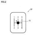
- Fig. 2 shows a shift pattern SP of the transmission 10.
- the driver operates the shift lever 13 according to the shift pattern SP.
- the gear pairs which are used for the transmission of rotation between the input shaft 11 and the output shaft 12 are changed, and the shift stages are changed.
- the transmission 10 is configured so as to be allowed to change its state to a neutral state where the transmission of rotation between the input shaft 11 and the output shaft 12 is shut off.
- the shift lever 13 is operated to a neutral position, the state of the transmission 10 is changed to the neutral state.
- a structure of the transmission 10 is the same as a structure of a well known manual transmission which is mounted on a vehicle. Thereby, a detailed description of the structure of the transmission 10 will be omitted.
- the input shaft 11 of the transmission 10 is connected with the rotor shaft 3a of the MG 3 via a first clutch 20.
- the first clutch 20 is a well known friction clutch.
- the first clutch 20 is configured so as to be allowed to switch its state between a fully engaged state where the input shaft 11 and the rotor shaft 3a rotate integrally with each other and a release state where the input shaft 11 and the rotor shaft 3a are separated from each other.
- the first clutch 20 is allowed to switch its state to a state (hereinafter, referred to as a half clutch) where a power is transmitted between the rotor shaft 3a and the input shaft 11 while the rotor shaft 3a and the input shaft 11 rotate at different rotating speeds from each other.
- the first clutch 20 is operated by a clutch pedal CP.
- the clutch pedal CP When the clutch pedal CP is stepped on, the state of the first clutch 20 is switched to the release state.
- the clutch pedal CP When the clutch pedal CP is released, the state of the first clutch 20 is switched to the fully engaged state. Furthermore, when the clutch pedal CP is partially stepped on, the state of the first clutch 20 is switched to the half clutch.
- the relation between the clutch pedal CP and the state of the first clutch 20 is the same as the relation in a well known manual clutch. Thereby, a detailed description of the relation between the first clutch 20 and the clutch pedal CP will be omitted.
- the rotor shaft 3a of the MG 3 is connected with the output shaft 2a of the engine 2 via a second clutch 21.
- the second clutch 21 is also a well known friction clutch.
- the second clutch 21 is configured so as to be allowed to switch its state between an engaged state where the output shaft 2a and the rotor shaft 3a rotate integrally and a release state where the output shaft 2a and the rotor shaft 3a are separated from each other.
- the second clutch 21 includes an actuator 21a for switching the state of the second clutch 21. As described above, the second clutch 21 is configured as an automatic clutch.
- the output shaft 12 of the transmission 10 is connected with a differential mechanism 4.
- the differential mechanism 4 is a well known mechanism which distributes inputted power to the right and left drive wheels 5. In this figure, only one of the drive wheels 5 is shown.
- the vehicle control apparatus 30 is configured as a computer unit including a microprocessor and peripheral devices, such as a RAM and a ROM, which are necessary for the operations of the microprocessor.
- the vehicle control apparatus 30 holds various control programs for making the vehicle 1A travel appropriately.
- the vehicle control apparatus 30 controls control objects such as the engine 2 and the MG 3 by executing these programs.
- the vehicle control apparatus 30 is connected with various sensors for obtaining information with respect to the vehicle 1A.
- the vehicle control apparatus 30 is connected with an accelerator opening degree sensor 31, a wheel speed sensor 32, and a crank angle sensor 33, for example.
- the accelerator opening degree sensor 31 outputs a signal corresponding to an operation amount to the accelerator pedal, that is, an accelerator opening degree.
- the wheel speed sensor 32 outputs a signal corresponding to a rotating speed of the drive wheel 5.
- the crank angle sensor 33 outputs a signal corresponding to a rotating speed (the number of revolutions) of the output shaft 2a of the engine 2.
- various sensors are further connected to the vehicle control apparatus 30, but they are omitted in the figure.
- plural traveling modes are realized by controlling the operations of the engine 2, the MG 3, and the second clutch 41.
- an EV traveling mode an engine traveling mode, and so on are set.
- the state of the second clutch 21 is switched to the release state, and the engine 2 is stopped.
- the vehicle 1A is made to travel by power of the MG 3.
- the EV traveling mode corresponds to an electrical traveling mode of the present invention.
- the engine traveling mode the state of the second clutch 21 is switched to the engaged state.
- the vehicle 1 is made to travel by power of the engine 2 mainly.
- the vehicle control apparatus 30 switches these traveling modes based on a driving power required to the vehicle 1A by the driver.
- the vehicle control apparatus 30 switches the traveling mode to the EV travel mode.
- the vehicle control apparatus 30 switches the traveling mode to the engine traveling mode.
- the driver decreases the accelerator opening degree, when the driver changes the gear stage to a higher gear stage from the present gear stage, that is, performs an upshift operation. And, the driver may step on the accelerator pedal slowly after completing the upshift. In this case, there is a possibility that a state that the accelerator opening degree is equal to or less than the above determination opening degree is continued for the determination switching time or more.
- the vehicle control apparatus 30 controls a switching of the traveling mode so that an unnecessary switching of the traveling mode to the EV traveling mode is not performed during the gear shifting and after the gear shifting is completed.
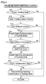
- Fig. 3 shows a traveling mode switching control routine which the vehicle control apparatus 30 executes for controlling the switching of the traveling mode in this manner.
- the vehicle control apparatus 30 repeatedly executes this control routine at predetermined intervals while the vehicle 1A is traveling. Furthermore, the vehicle control apparatus 30 executes this control routine in parallel to the other routines executed by the vehicle control apparatus 30. By executing this control routine, the vehicle control apparatus 30 functions as a switching restriction device of the present invention.
- the vehicle control apparatus 30 first determines whether or not the present traveling mode is the engine traveling mode in step S11. When the vehicle control apparatus 30 determines that the present traveling mode is not the engine traveling mode, the vehicle control apparatus 30 ends the present control routine. On the other hand, when the vehicle control apparatus 30 determines that the present traveling mode is the engine traveling mode, the vehicle control apparatus 30 goes to the step S12 and obtains a traveling state of the vehicle 1A. The vehicle control apparatus 30 obtains the accelerator opening degree, the rotating speed of the drive wheel 5, the rotating speed of the output shaft 2a of the engine 2, and so on as the traveling state of the vehicle 1A. Furthermore, the vehicle control apparatus 30 also obtains the present gear stage in this step.
- the gear stage may be obtained based on a ratio between the rotating speed of the drive wheel 5 and the rotating speed of the output shaft 2a, for example.
- the vehicle control apparatus 30 determines whether or not the gear shifting has been required to the vehicle 1A. If the gear shifting is required, the clutch pedal CP is stepped on and the state of the first clutch 20 is switched to the release state. Thus, for example, the gear ratio of the present gear stage and a ratio between the rotating speed of the output shaft 2a and the rotating speed of the drive wheel 5 are compared with each other. And, when the difference between these ratios is big, the vehicle control apparatus 30 may determine that the gear shifting has been required. When the vehicle control apparatus 30 determines that the gear shifting is not required, the vehicle control apparatus 30 skips steps S14 to S18 and goes to step S19.
- the vehicle control apparatus 30 determines that the gear shifting has been required, the vehicle control apparatus 30 goes to the step S14 and prohibits a switching determination of the traveling mode.
- the determination opening degree may be set to a value of 0 or less.
- the switching to the EV traveling mode is prohibited.
- the vehicle control apparatus 30 determines whether or not the gear shifting has been completed. When the gear shifting has been completed, the gear stage of the transmission 10 has been changed to any one of the first gear to fifth gear and the state of the first clutch 20 has been switched to the fully engaged state.
- the vehicle control apparatus 30 may determine that the gear shifting has been completed.
- the vehicle control apparatus 30 determines that the gear shifting is still ongoing, the vehicle control apparatus 30 returns to the step S14 and executes the processes of the steps S14 and S15 repeatedly until the gear shifting is completed.
- the vehicle control apparatus 30 determines that the gear shifting is finished, the vehicle control apparatus 30 goes to the step S16 and resets a timer for measuring an elapsed time from a time when the gear shifting is completed, and then starts measuring the elapsed time.
- the vehicle control apparatus 30 restricts the switching determination of the traveling mode.
- the determination opening degree may be set to a value which is less than the normal determination opening degree.
- the driver steps on the accelerator pedal slowly while releasing the clutch pedal CP when the gear shifting has been completed. Thereby, when the state of the first clutch 20 has been switched to the fully engaged state, the accelerator opening degree is increased to some degree. Accordingly, by decreasing the determination opening degree in this manner, the switching to the EV traveling mode is restricted.
- the vehicle control apparatus 30 determines whether or not a value of the timer is greater than a predetermined determination value.
- the determination value is set to a time in which it is possible to prevent the unnecessary switching of the traveling mode to the EV traveling mode when the gear shifting has been completed, for example. In particular, the determination value is set to a few seconds.
- the vehicle control apparatus 30 determines that the value of the timer is equal to or less than the determination value, the vehicle control apparatus 30 returns to the step S17 and executes the processes of the steps S17 and S18 repeatedly until the value of the timer is greater than the determination value.
- the determination value corresponds to a switching restriction time of the present invention.
- the vehicle control apparatus 30 determines that the value of the timer is greater than the determination value, the vehicle control apparatus 30 goes to the step S19 and executes a normal switching determination of the traveling mode. In other words, the switching determination of the traveling mode is executed with the normal determination opening degree. Thereafter, the vehicle control apparatus 30 ends the present control routine.
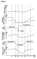
- Fig. 4 shows temporal variations of the wheel speed, the accelerator opening degree, the shift position, the rotating speed of the input shaft 11, the state of the first clutch 20, and the rotating speed of the engine 2 during the gear shifting to a fourth gear from a third gear. Furthermore, in this graph, a temporal variation of the determination opening degree is shown by an alternate long and short dash line L.
- the accelerator opening degree is deceased gradually from time t1 because of the gear shifting.
- the clutch pedal CP begins to be stepped on at time t2. Thereby, the step S13 in Fig. 3 is affirmative at the time t2, and the switching determination of the traveling mode is prohibited. Accordingly, the determination value is set to the value of 0 or less.
- the state of the first clutch 20 is switched to the release state at time t3. Furthermore, the shift lever 13 is changed to the neutral position from the third gear position at the time t3. Thereafter, the shift lever 13 is changed to the fourth gear position at time t4. And, the clutch pedal CP is released gradually from time t5, and the state of the first clutch 20 is switched to the engaged state at time t6. Thereby, the step S15 in Fig. 3 is affirmative at the time t6, and the switching determination of the traveling mode is restricted. Accordingly, the value of the determination opening degree is set to a value which is greater than 0 and is less than the normal determination opening degree. Furthermore, as shown in this graph, the accelerator pedal is stepped on slowly from the time t5 to time t7. Thereafter, at time t8, an affirmative determination is obtained in the step S18 in Fig. 3 , and the value of the determination opening degree is returned to the normal determination opening degree.
- the determination opening degree is less than the accelerator opening degree in a period from shortly after the time t2 to the time t8.
- the traveling mode is hard to switch to the EV traveling mode during the gear shifting and for a while after the gear shifting is completed.
- the switching determination of the traveling mode is prohibited during the gear shifting, it is possible to prevent the traveling mode from switching to the EV traveling mode. Furthermore, the switching determination of the traveling mode is restricted for a while after the gear shifting is completed. Thereby, even though the accelerator pedal is stepped on slowly, it is possible to suppress switching the traveling mode to the EV traveling mode. Accordingly, it is possible to prevent an unnecessary stop of the engine 2 during the gear shifting and for a while after the gear shifting is completed. As the result, since it is possible to decrease the number of times the engine 2 is made to restart, it is possible to improve fuel efficiency.
- the second clutch 21 is not limited to the friction clutch.
- the second clutch 21 can be a clutch which is able to transmit and shut off a power transmission between the output shaft 2a of the engine 2 and the rotor shaft 3a of the MG 3.
- the second clutch 21 can be an electromagnetic clutch or a dog clutch, for example.
- the determination method in the step S13 of Fig. 3 is not limited to the above described determination method.
- the vehicle control apparatus 30 may determine that the gear shifting is required when the clutch pedal is stepped on.
- the transmission 10 is provided with a neutral switch which outputs a signal when the shift lever 13 is in the neutral position
- the vehicle control apparatus 30 may determine that the gear shifting is required when the signal is output from the neutral switch.
- the vehicle control apparatus 30 may determine that the gear shifting is required by using the rotating speed of the input shaft 11 instead of the rotating speed of the engine 2.
- the gear ratio of the present gear stage and a ratio between the rotating speed of the input shaft 11 and the rotating speed of the drive wheel 5 are compared with each other. And, when the difference between these ratios is big, the vehicle control apparatus 30 may determine that the gear shifting is required.
- the determination method in the step S15 of Fig. 3 is not limited to the above described determination method.
- the vehicle control apparatus 30 may determine that the gear shifting is completed when the clutch pedal is released.
- the vehicle control apparatus 30 may determine that the gear shifting is completed when a signal corresponding to any one of the gear stages is output from the shift sensor.
- the vehicle control apparatus 30 may determine whether or not the gear shifting is required by using the rotating speed of the input shaft 11 instead of the rotating speed of the engine 2. In this case, for example, when a ratio between the rotating speed of the input shaft 11 and the rotating speed of the drive wheel 5 is almost the same as a gear ratio of any one of the gear stages of the transmission 10, the vehicle control apparatus 30 may determine that the gear shifting is completed.
- a method for restricting the switching determination of the traveling mode is not limited to the above method.
- the traveling mode is switched to the EV traveling mode from the engine traveling mode in a case that the state that the accelerator opening degree is less than the predetermined determination opening degree is continued for the determination switching time or more.
- the switching determination of the traveling mode may be restricted.
- a hybrid vehicle to which the present invention is applied is not limited to the vehicle shown in Fig. 1 and Fig. 2 .
- the present invention may be applied to various vehicles which have a transmission which allows the driver to manipulate the gear shifting, and are able to make the vehicle to travel with only the MG 3 while separating the engine 2 from the drive wheels 5.
- Hybrid vehicles according to other embodiments to which the present invention is applied will be described with reference to Figs. 5 to 10 .
- the same components as those in Fig. 1 or Fig. 2 are denoted by the same reference numerals, and descriptions thereof will be omitted.
- Fig. 5 schematically shows main portions of a hybrid vehicle 1B according to this embodiment.
- the first clutch 20 is an automatic clutch.
- the vehicle 1B has a shift device 41 for the driver to instruct to change the gear stages.
- the shift device 41 is connected with the vehicle control apparatus 30.
- the shift device 41 outputs a signal corresponding to a selected gear stage.
- the vehicle control apparatus 30 changes the gear stage of the transmission 40 based on the output signal from the shift device 41.
- Fig. 6 is an enlarged view showing the shift device 41.
- the gear stage is selected when the shift lever 13 is operated to the positions of "+” or "-” shown in this figure.
- the vehicle control apparatus 30 upshifts by one stage, when the shift lever 13 is operated to the "+” position.
- the vehicle control apparatus 30 downshifts by one stage, when the shift lever 13 is operated to the "-" position.
- the vehicle control apparatus 30 controls the operation of the first clutch 20 so that the gear stages of the transmission 40 are changed without an engine stall.
- the transmission 40 is configured as a semi-automatic transmission.
- the EV traveling mode and the engine traveling mode are realized as the traveling modes.
- the state of the second clutch 21 is switched to the release state, and the engine 2 is stopped. And, the vehicle 1B is made to travel with the power of the MG 3.
- the state of the second clutch 21 is switched to the engaged state. And, the vehicle 1B is made to travel mainly with the power of the engine 2 mainly.
- the vehicle control apparatus 30 switches these traveling modes based on the accelerator opening degree.
- the driver may decrease the accelerator opening degree when performing an upshift operation, and may step on the accelerator pedal slowly after the gear shifting is completed.
- the present invention it is possible to prevent an unnecessary stop of the engine 2 during the gear shifting and for a while after the gear shifting is completed. Thereby, it is possible to improve fuel efficiency.
- FIG. 7 A second other embodiment will be described with reference to Fig. 7 .
- This figure schematically shows main portions of a hybrid vehicle 1C according to the second other embodiment.
- the first clutch 20 is omitted.
- the input shaft 11 of a transmission 50 and the rotor shaft 3a of the MG 3 are connected with each other so as to rotate integrally.
- a well known torque converter is provided in the transmission 50. That is, the transmission 50 is configured as an automatic transmission.
- the vehicle 1C also has the shift device 41 as with the vehicle 1B mentioned above. Thereby, in the vehicle 1C, the driver is able to select the gear stage.
- the EV traveling mode and the engine traveling mode are realized as the traveling modes.
- the state of the second clutch 21 is switched to the release state, and the engine 2 is stopped. And, the vehicle 1C is made to travel with the power of the MG 3.
- the state of the second clutch 21 is switched to the engaged state. And, the vehicle 1C is made to travel with the power of the engine 2 mainly.
- the vehicle control apparatus 30 switches these traveling modes based on the accelerator opening degree.
- the driver may decrease the accelerator opening degree when performing an upshift operation, and may steps on the accelerator pedal slowly after the gear shifting is completed.
- the present invention it is possible to prevent an unnecessary stop of the engine 2 during the gear shifting and for a while after the gear shifting is completed. Thereby, it is possible to improve fuel efficiency.
- FIG. 8 A third other embodiment will be described with reference to Fig. 8 .
- This figure schematically shows main portions of a hybrid vehicle 1D according to the third other embodiment.
- the output shaft 2a of the engine 2 and the input shaft 11 of the transmission 10 are connected with each other via a clutch 60.
- the clutch 60 is an automatic clutch.
- the output shaft 12 of the transmission 10 and the rotor shaft 3a of the MG 3 are connected with each other so as to rotate integrally.
- the rotor shaft 3a of the MG 3 is also connected with the differential mechanism 4.
- a clutch pedal sensor 61 is provided on the clutch pedal CP.
- the vehicle 1D has a clutch-by-wire system which determines requests of the driver and requests of a control system to control the clutch 60.
- the EV traveling mode and the engine traveling mode are realized as the traveling modes.
- the clutch 60 is released, and the engine 2 is stopped. And, the vehicle 1D is made to travel with the power of the MG 3.
- the clutch 60 is controlled according to the requests of the driver. And, the vehicle 1D is made to travel mainly with the power of the engine 2.
- the vehicle control apparatus 30 switches these traveling modes based on the accelerator opening degree.
- the driver may decrease the accelerator opening degree when performing an upshift operation, and may step on the accelerator pedal slowly after the gear shifting is completed.
- the clutch 60 can be a manual-type clutch. In this case, in the EV traveling mode, the state of the transmission 10 may be switched to the neutral state. As the result, it is possible to separate the engine 2 and the MG 3 from each other.
- FIG. 9 This figure schematically shows main portions of a hybrid vehicle 1E according to the fourth other embodiment.
- the vehicle 1E has the transmission 40 which is configured as the semi-automatic transmission as with the first other embodiment.
- the transmission 40 is provided between the engine 2 and the MG 3 as with the third other embodiment.
- the output shaft 2a of the engine 2 and the input shaft 11 of the transmission 40 are connected with each other via a clutch 70.
- the clutch 70 is the automatic clutch as with the above second clutch 21.
- the output shaft 12 of the transmission 40 and the rotor shaft 3a of the MG 3 are connected with each other so as to rotate integrally.
- the rotor shaft 3a of the MG 3 is also connected with the differential mechanism 4.
- the EV traveling mode and the engine traveling mode are realized as the traveling modes.
- a state of the clutch 70 is switched to a release state, and the engine 2 is stopped. And, the vehicle 1E is made to travel with the power of the MG 3.
- the state of the clutch 70 is switched to an engaged state. And, the vehicle 1E is made to travel mainly with the power of the engine 2.
- the vehicle control apparatus 30 switches these traveling modes based on the accelerator opening degree.
- the driver may decrease the accelerator opening degree when performing an upshift operation, and may step on the accelerator pedal slowly after the gear shifting is completed.
- the present invention it is possible to prevent an unnecessary stop of the engine 2 during the gear shifting and for a while after the gear shifting is completed. Thereby, it is possible to improve fuel efficiency.
- FIG. 10 A fifth other embodiment will be described with reference to Fig. 10 .
- the vehicle 1F has the transmission 50 which is configured as the automatic transmission as with the second other embodiment.
- the transmission 50 is provided between the engine 2 and the MG 3 as with the third other embodiment.
- the output shaft 2a of the engine 2 and the input shaft 11 of the transmission 50 are connected with each other so as to rotate integrally.
- the output shaft 12 of the transmission 50 is connected with the rotor shaft 3a of the MG 3 so as to rotate integrally.
- the rotor shaft 3a of the MG 3 is also connected with the differential mechanism 4.
- the EV traveling mode and the engine traveling mode are realized as the traveling modes.
- a state of the transmission 50 is switched to the neutral state, and the engine 2 is stopped. And, the vehicle 1F is made to travel with the power of the MG 3.
- a gear stage of the transmission 50 is changed to an appropriate gear stage. And, the vehicle 1F is made to travel mainly with the power of the engine 2.
- the vehicle control apparatus 30 switches these traveling modes based on the accelerator opening degree.
- the driver may decrease the accelerator opening degree when performing an upshift operation, and may step on the accelerator pedal slowly after the gear shifting is completed.
- the present invention it is possible to prevent an unnecessary stop of the engine 2 during the gear shifting and for a while after the gear shifting is completed. Thereby, it is possible to improve fuel efficiency.
- the transmission of the vehicle to which the present invention is applied is not limited to a transmission the top gear of which is a 5th gear.
- the transmission may be a transmission the top gear of which is a 4th gear or less, or 6th gear or more, for example.
- the hybrid vehicle to which the present invention is applied may have an electric motor instead of the motor generator.
Landscapes
- Engineering & Computer Science (AREA)
- Transportation (AREA)
- Mechanical Engineering (AREA)
- Chemical & Material Sciences (AREA)
- Combustion & Propulsion (AREA)
- Automation & Control Theory (AREA)
- Hybrid Electric Vehicles (AREA)
- Control Of Transmission Device (AREA)
- Electric Propulsion And Braking For Vehicles (AREA)
Abstract
Description
- The present invention relates to a control apparatus applied to a hybrid vehicle: having an internal combustion engine and an electric motor as driving sources for traveling; being provided with a transmission changing gear stages in response to an operation of a shift lever on a power transmission path between the internal combustion engine and drive wheels; and being allowed to travel in an electrical traveling mode where the internal combustion engine is stopped and the drive wheels are driven by the electric motor and an engine traveling mode where the drive wheels are driven by the internal combustion engine.
- There is known a hybrid vehicle having an internal combustion engine and a motor generator as driving sources for traveling. In the hybrid vehicle, an electrical traveling mode where the internal combustion engine is stopped and the vehicle is made to travel by the electric motor; and an engine traveling mode where the vehicle is made to travel by the internal combustion engine are set, and these traveling modes are switched according to a required driving power to the vehicle. Furthermore, there is known a hybrid vehicle where an automatic transmission is mounted and the electric motor and the internal combustion engine are connected with an input side of the transmission and the drive wheels are connected with an output side of the transmission. In addition, as a control apparatus of this vehicle, there is known an apparatus switching the traveling mode to the electrical traveling mode in a case that an accelerator opening degree is equal to or less than a determination value and a predetermined delay time has passed when the traveling mode is the engine traveling mode (see Patent Literature 1). In the control apparatus, in a case that a driver performs an on/off operation to an accelerator pedal frequently when the traveling mode is the engine traveling mode, the delay time is increased and a switching to the electrical traveling mode is suppressed. Furthermore, in the control apparatus, in a case that the transmission is being upshifted when the traveling mode is the engine traveling mode, the traveling mode is switched to the electrical traveling mode after the upshift of the transmission is completed. In addition, there is Patent Literatures 2-4 as prior art references in relation to the present invention.
-
- Patent Literature 1:
JP-2009-234565A - Patent Literature 2:
JP-2010-184535A - Patent Literature 3:
JP-2010-202054A - Patent Literature 4:
JP-2009-292315A - There is known a hybrid vehicle having a transmission changing gear stages in response to an operation of a shift lever by a driver. When the driver drives the vehicle like this, the driver may step on the accelerator pedal slowly after a gear shifting for changing the gear stage to a higher gear stage from a present gear stage, that is, an upshift is completed. In the apparatus of the
Patent Literature 1, the switching to the electrical traveling mode is suppressed when the on/off operation to the accelerator pedal is performed frequently and during the upshift of the transmission. However, in the apparatus of thePatent Literature 1, a switching of the traveling mode is not suppressed when the accelerator pedal is stepped on slowly after the gear shifting is completed. Thereby, there is a possibility that the traveling mode is switched to the eletrical traveling mode after the gear shifting is completed even though the switching to the electrical traveling mode is unnecessary. - In view of the foregoing, one object of the present invention is to provide a control apparatus for a hybrid vehicle capable of preventing an unnecessary stop of an internal combustion engine during a gear shifting and for a while after the gear shifting is completed.
- A control apparatus of the present invention is applied to a hybrid vehicle, the hybrid vehicle having: an internal combustion engine and an electric motor as driving sources for traveling; and a transmission having plural gear stages where different gear ratios are set from each other and changing the gear stages in response to an operation to a shift lever, the transmission being provided in a power transmission path between the internal combustion engine and drive wheels, and the electric motor being provided so as to drive the drive wheels, and the hybrid vehicle being allowed to travel in an electric traveling mode where the internal combustion engine is stopped and the drive wheels are driven by the electric motor, and an engine traveling mode where the drive wheels are driven by the internal combustion engine, the control apparatus including a traveling mode switching device which switches a traveling mode of the vehicle to the electric traveling mode, in a case that the traveling mode switching device determines that an accelerator opening degree of the vehicle is less than a determination opening degree when the vehicle is in the engine traveling mode, wherein the control apparatus further includes a switching restriction device which restricts a switching of the traveling mode by the traveling mode switching device, so that the traveling mode of the vehicle is hard to switch to the electric traveling mode in a period from a start of a shift operation until a predetermined switching restriction time elapses after a change of the gear stage of the transmission is completed, in a case that the shift operation of the transmission is performed when the vehicle is in the engine traveling mode.
- According to the control apparatus of the present invention, by the switching restriction device, it is possible to restrict the switching to the electric traveling mode in the period from the start of the shift operation until the switching restriction time elapses after the gear shifting is completed. Thereby, it is possible to prevent an unnecessary stop of the internal combustion engine during the gear shifting and for a while after the gear shifting is completed. As the result, since it is possible to decrease the number of times the internal combustion engine is made to restart, it is possible to improve fuel efficiency.
- In one embodiment of the control apparatus of the present invention, the switching restriction device may prohibit the switching of the traveling mode to the electric traveling mode by the traveling mode switching device, in a period from the start of the shift operation until the change of the gear stage of the transmission is completed. In general, an accelerator opening degree becomes almost zero during the gear shifting. According to this embodiment, since the switching to the electric traveling mode is prohibited during the gear shifting, it is possible to prevent the unnecessary stop of the internal combustion engine.
- In one embodiment of the control apparatus of the present invention, the switching restriction device may decrease a value of the determination opening degree so as to be less than a value of the determination opening degree which is set when the switching of the traveling mode of the vehicle is not restricted, in a period from the change of the gear stage of the transmission is completed until the predetermined switching restriction time elapses. By decreasing the value of the determination opening degree in this manner, even though an accelerator pedal is stepped on slowly after the gear shifting is completed, it is possible to prevent the unnecessary stop of the internal combustion engine.
-
-
Fig. 1 is a schematic diagram showing main portions of a vehicle where a control apparatus according to one embodiment of the present invention is incorporated. -
Fig. 2 is a diagram showing a shift pattern of a transmission. -
Fig. 3 is a flowchart showing a traveling mode determination control routine executed by a vehicle control apparatus. -
Fig. 4 is a graph showing temporal variations of a wheel speed, an accelerator opening degree, a shift position, a rotating speed of an input shaft of a transmission, a state of a first clutch, and a rotating speed of an engine during a gear shifting to a fourth gear from a third gear. -
Fig. 5 is a schematic diagram showing main portions of a hybrid vehicle according to a first other embodiment which is applied to the present invention. -
Fig. 6 is an enlarged diagram showing a gear stage changing mechanism which is provided on a transmission of the hybrid vehicle ofFig. 5 . -
Fig. 7 is a schematic diagram showing main portions of a hybrid vehicle according to a second other embodiment which is applied to the present invention. -
Fig. 8 is a schematic diagram showing main portions of a hybrid vehicle according to a third other embodiment which is applied to the present invention. -
Fig. 9 is a schematic diagram showing main portions of a hybrid vehicle according to a fourth other embodiment which is applied to the present invention. -
Fig. 10 is a schematic diagram showing main portions of a hybrid vehicle according to a fifth other embodiment which is applied to the present invention. -
Fig. 1 schematically shows main portions of a vehicle where a control apparatus according to one embodiment of the present invention is incorporated. Thevehicle 1A includes an internal combustion engine (hereinafter, referred to as an engine) 2 and a motor generator (hereinafter, referred to as an MG) 3 as an electric motor, as driving sources for travelling. That is, thevehicle 1A is configured as a hybrid vehicle. Theengine 2 is a well known spark ignition type internal combustion engine which is mounted on the hybrid vehicle. The MG 3 is a well known motor generator which functions as an electric motor and a generator, and is mounted on the hybrid vehicle. - Furthermore, a
transmission 10 is mounted on thevehicle 1A. Thetransmission 10 is configured as a manual transmission providing one-five forward gear stages and one reverse gear stage. Thetransmission 10 includes aninput shaft 11 and anoutput shaft 12. Gear pairs (not shown) which correspond to first gear to fifth gear are provided between theinput shaft 11 and theoutput shaft 12. Gear ratios are set to the gear pairs respectively, each of the gear ratios differing from each other. The gear ratios are set so as to get smaller in the order of the gear pair of the first gear, the gear pair of the second gear, the gear pair of the third gear, the gear pair of the fourth gear, and the gear pair of the fifth gear. Thetransmission 10 is configured so as to establish a transmission of rotation selectively by any one of the gear pairs. Thetransmission 10 includes ashift lever 13 which is operated by a driver.Fig. 2 shows a shift pattern SP of thetransmission 10. The driver operates theshift lever 13 according to the shift pattern SP. By the operation, the gear pairs which are used for the transmission of rotation between theinput shaft 11 and theoutput shaft 12 are changed, and the shift stages are changed. Furthermore, thetransmission 10 is configured so as to be allowed to change its state to a neutral state where the transmission of rotation between theinput shaft 11 and theoutput shaft 12 is shut off. When theshift lever 13 is operated to a neutral position, the state of thetransmission 10 is changed to the neutral state. A structure of thetransmission 10 is the same as a structure of a well known manual transmission which is mounted on a vehicle. Thereby, a detailed description of the structure of thetransmission 10 will be omitted. - As shown in
Fig. 1 , theinput shaft 11 of thetransmission 10 is connected with therotor shaft 3a of the MG 3 via afirst clutch 20. The first clutch 20 is a well known friction clutch. The first clutch 20 is configured so as to be allowed to switch its state between a fully engaged state where theinput shaft 11 and therotor shaft 3a rotate integrally with each other and a release state where theinput shaft 11 and therotor shaft 3a are separated from each other. Furthermore, the first clutch 20 is allowed to switch its state to a state (hereinafter, referred to as a half clutch) where a power is transmitted between therotor shaft 3a and theinput shaft 11 while therotor shaft 3a and theinput shaft 11 rotate at different rotating speeds from each other. The first clutch 20 is operated by a clutch pedal CP. When the clutch pedal CP is stepped on, the state of the first clutch 20 is switched to the release state. When the clutch pedal CP is released, the state of the first clutch 20 is switched to the fully engaged state. Furthermore, when the clutch pedal CP is partially stepped on, the state of the first clutch 20 is switched to the half clutch. The relation between the clutch pedal CP and the state of the first clutch 20 is the same as the relation in a well known manual clutch. Thereby, a detailed description of the relation between the first clutch 20 and the clutch pedal CP will be omitted. - The
rotor shaft 3a of theMG 3 is connected with theoutput shaft 2a of theengine 2 via asecond clutch 21. The second clutch 21 is also a well known friction clutch. The second clutch 21 is configured so as to be allowed to switch its state between an engaged state where theoutput shaft 2a and therotor shaft 3a rotate integrally and a release state where theoutput shaft 2a and therotor shaft 3a are separated from each other. The second clutch 21 includes anactuator 21a for switching the state of thesecond clutch 21. As described above, the second clutch 21 is configured as an automatic clutch. - The
output shaft 12 of thetransmission 10 is connected with adifferential mechanism 4. Thedifferential mechanism 4 is a well known mechanism which distributes inputted power to the right and leftdrive wheels 5. In this figure, only one of thedrive wheels 5 is shown. - Operations of the
engine 2, theMG 3, and the second clutch 21 are controlled by avehicle control apparatus 30. Thevehicle control apparatus 30 is configured as a computer unit including a microprocessor and peripheral devices, such as a RAM and a ROM, which are necessary for the operations of the microprocessor. Thevehicle control apparatus 30 holds various control programs for making thevehicle 1A travel appropriately. Thevehicle control apparatus 30 controls control objects such as theengine 2 and theMG 3 by executing these programs. Thevehicle control apparatus 30 is connected with various sensors for obtaining information with respect to thevehicle 1A. Thevehicle control apparatus 30 is connected with an acceleratoropening degree sensor 31, awheel speed sensor 32, and acrank angle sensor 33, for example. The acceleratoropening degree sensor 31 outputs a signal corresponding to an operation amount to the accelerator pedal, that is, an accelerator opening degree. Thewheel speed sensor 32 outputs a signal corresponding to a rotating speed of thedrive wheel 5. Thecrank angle sensor 33 outputs a signal corresponding to a rotating speed (the number of revolutions) of theoutput shaft 2a of theengine 2. In addition, various sensors are further connected to thevehicle control apparatus 30, but they are omitted in the figure. - In the
vehicle 1A, plural traveling modes are realized by controlling the operations of theengine 2, theMG 3, and thesecond clutch 41. As the plural traveling modes, an EV traveling mode, an engine traveling mode, and so on are set. In the EV traveling mode, the state of the second clutch 21 is switched to the release state, and theengine 2 is stopped. And, thevehicle 1A is made to travel by power of theMG 3. Thereby, the EV traveling mode corresponds to an electrical traveling mode of the present invention. On the other hand, in the engine traveling mode, the state of the second clutch 21 is switched to the engaged state. And, thevehicle 1 is made to travel by power of theengine 2 mainly. Thevehicle control apparatus 30 switches these traveling modes based on a driving power required to thevehicle 1A by the driver. For example, when a state that the accelerator opening degree is less than a predetermined determination opening degree is continued for a predetermined determination switching time or more, thevehicle control apparatus 30 switches the traveling mode to the EV travel mode. On the other hand, when a state that the accelerator opening degree is equal to or greater than the determination opening degree is continued for the predetermined determination switching time or more, thevehicle control apparatus 30 switches the traveling mode to the engine traveling mode. By switching the traveling mode in this manner, thevehicle control apparatus 30 functions as a traveling mode switching device of the present invention. - The driver decreases the accelerator opening degree, when the driver changes the gear stage to a higher gear stage from the present gear stage, that is, performs an upshift operation. And, the driver may step on the accelerator pedal slowly after completing the upshift. In this case, there is a possibility that a state that the accelerator opening degree is equal to or less than the above determination opening degree is continued for the determination switching time or more. The
vehicle control apparatus 30 controls a switching of the traveling mode so that an unnecessary switching of the traveling mode to the EV traveling mode is not performed during the gear shifting and after the gear shifting is completed.Fig. 3 shows a traveling mode switching control routine which thevehicle control apparatus 30 executes for controlling the switching of the traveling mode in this manner. Thevehicle control apparatus 30 repeatedly executes this control routine at predetermined intervals while thevehicle 1A is traveling. Furthermore, thevehicle control apparatus 30 executes this control routine in parallel to the other routines executed by thevehicle control apparatus 30. By executing this control routine, thevehicle control apparatus 30 functions as a switching restriction device of the present invention. - In the control routine, the
vehicle control apparatus 30 first determines whether or not the present traveling mode is the engine traveling mode in step S11. When thevehicle control apparatus 30 determines that the present traveling mode is not the engine traveling mode, thevehicle control apparatus 30 ends the present control routine. On the other hand, when thevehicle control apparatus 30 determines that the present traveling mode is the engine traveling mode, thevehicle control apparatus 30 goes to the step S12 and obtains a traveling state of thevehicle 1A. Thevehicle control apparatus 30 obtains the accelerator opening degree, the rotating speed of thedrive wheel 5, the rotating speed of theoutput shaft 2a of theengine 2, and so on as the traveling state of thevehicle 1A. Furthermore, thevehicle control apparatus 30 also obtains the present gear stage in this step. The gear stage may be obtained based on a ratio between the rotating speed of thedrive wheel 5 and the rotating speed of theoutput shaft 2a, for example. In the next step S13, thevehicle control apparatus 30 determines whether or not the gear shifting has been required to thevehicle 1A. If the gear shifting is required, the clutch pedal CP is stepped on and the state of the first clutch 20 is switched to the release state. Thus, for example, the gear ratio of the present gear stage and a ratio between the rotating speed of theoutput shaft 2a and the rotating speed of thedrive wheel 5 are compared with each other. And, when the difference between these ratios is big, thevehicle control apparatus 30 may determine that the gear shifting has been required. When thevehicle control apparatus 30 determines that the gear shifting is not required, thevehicle control apparatus 30 skips steps S14 to S18 and goes to step S19. - On the other hand, the
vehicle control apparatus 30 determines that the gear shifting has been required, thevehicle control apparatus 30 goes to the step S14 and prohibits a switching determination of the traveling mode. In this process, for example, the determination opening degree may be set to a value of 0 or less. As a result, the switching to the EV traveling mode is prohibited. In the next step S15, thevehicle control apparatus 30 determines whether or not the gear shifting has been completed. When the gear shifting has been completed, the gear stage of thetransmission 10 has been changed to any one of the first gear to fifth gear and the state of the first clutch 20 has been switched to the fully engaged state. Thus, when the ratio between the rotating speed of thedrive wheel 5 and the rotating speed of theoutput shaft 2a is almost the same as a gear ratio which is any one of the gear ratios of the gear stages of thetransmission 10, thevehicle control apparatus 30 may determine that the gear shifting has been completed. When thevehicle control apparatus 30 determines that the gear shifting is still ongoing, thevehicle control apparatus 30 returns to the step S14 and executes the processes of the steps S14 and S15 repeatedly until the gear shifting is completed. - On the other hand, when the
vehicle control apparatus 30 determines that the gear shifting is finished, thevehicle control apparatus 30 goes to the step S16 and resets a timer for measuring an elapsed time from a time when the gear shifting is completed, and then starts measuring the elapsed time. In the nest step S17, thevehicle control apparatus 30 restricts the switching determination of the traveling mode. A determination opening degree in a case that the switching determination of the traveling mode is neither prohibited nor restricted, is referred to as a normal determination opening degree. In this process, the determination opening degree may be set to a value which is less than the normal determination opening degree. In general, the driver steps on the accelerator pedal slowly while releasing the clutch pedal CP when the gear shifting has been completed. Thereby, when the state of the first clutch 20 has been switched to the fully engaged state, the accelerator opening degree is increased to some degree. Accordingly, by decreasing the determination opening degree in this manner, the switching to the EV traveling mode is restricted. - In the next step S18, the
vehicle control apparatus 30 determines whether or not a value of the timer is greater than a predetermined determination value. The determination value is set to a time in which it is possible to prevent the unnecessary switching of the traveling mode to the EV traveling mode when the gear shifting has been completed, for example. In particular, the determination value is set to a few seconds. When thevehicle control apparatus 30 determines that the value of the timer is equal to or less than the determination value, thevehicle control apparatus 30 returns to the step S17 and executes the processes of the steps S17 and S18 repeatedly until the value of the timer is greater than the determination value. Thereby, the determination value corresponds to a switching restriction time of the present invention. - On the other hand, when the
vehicle control apparatus 30 determines that the value of the timer is greater than the determination value, thevehicle control apparatus 30 goes to the step S19 and executes a normal switching determination of the traveling mode. In other words, the switching determination of the traveling mode is executed with the normal determination opening degree. Thereafter, thevehicle control apparatus 30 ends the present control routine. -
Fig. 4 shows temporal variations of the wheel speed, the accelerator opening degree, the shift position, the rotating speed of theinput shaft 11, the state of the first clutch 20, and the rotating speed of theengine 2 during the gear shifting to a fourth gear from a third gear. Furthermore, in this graph, a temporal variation of the determination opening degree is shown by an alternate long and short dash line L. In an example of this graph, the accelerator opening degree is deceased gradually from time t1 because of the gear shifting. And, the clutch pedal CP begins to be stepped on at time t2. Thereby, the step S13 inFig. 3 is affirmative at the time t2, and the switching determination of the traveling mode is prohibited. Accordingly, the determination value is set to the value of 0 or less. - Thereafter, the state of the first clutch 20 is switched to the release state at time t3. Furthermore, the
shift lever 13 is changed to the neutral position from the third gear position at the time t3. Thereafter, theshift lever 13 is changed to the fourth gear position at time t4. And, the clutch pedal CP is released gradually from time t5, and the state of the first clutch 20 is switched to the engaged state at time t6. Thereby, the step S15 inFig. 3 is affirmative at the time t6, and the switching determination of the traveling mode is restricted. Accordingly, the value of the determination opening degree is set to a value which is greater than 0 and is less than the normal determination opening degree. Furthermore, as shown in this graph, the accelerator pedal is stepped on slowly from the time t5 to time t7. Thereafter, at time t8, an affirmative determination is obtained in the step S18 inFig. 3 , and the value of the determination opening degree is returned to the normal determination opening degree. - As shown in this graph, by executing the control routine of
Fig. 3 , the determination opening degree is less than the accelerator opening degree in a period from shortly after the time t2 to the time t8. Thereby, the traveling mode is hard to switch to the EV traveling mode during the gear shifting and for a while after the gear shifting is completed. - As described above, in the present invention, since the switching determination of the traveling mode is prohibited during the gear shifting, it is possible to prevent the traveling mode from switching to the EV traveling mode. Furthermore, the switching determination of the traveling mode is restricted for a while after the gear shifting is completed. Thereby, even though the accelerator pedal is stepped on slowly, it is possible to suppress switching the traveling mode to the EV traveling mode. Accordingly, it is possible to prevent an unnecessary stop of the
engine 2 during the gear shifting and for a while after the gear shifting is completed. As the result, since it is possible to decrease the number of times theengine 2 is made to restart, it is possible to improve fuel efficiency. - In the above described embodiment, the second clutch 21 is not limited to the friction clutch. The second clutch 21 can be a clutch which is able to transmit and shut off a power transmission between the
output shaft 2a of theengine 2 and therotor shaft 3a of theMG 3. Thereby, the second clutch 21 can be an electromagnetic clutch or a dog clutch, for example. - The determination method in the step S13 of
Fig. 3 is not limited to the above described determination method. For example, in a case that thevehicle 1A is provided with a clutch pedal sensor which outputs a signal depending on whether or not the clutch pedal CP is stepped on, thevehicle control apparatus 30 may determine that the gear shifting is required when the clutch pedal is stepped on. Furthermore, in a case that thetransmission 10 is provided with a neutral switch which outputs a signal when theshift lever 13 is in the neutral position, thevehicle control apparatus 30 may determine that the gear shifting is required when the signal is output from the neutral switch. In addition, in a case that thetransmission 10 is provided with an input shaft rotating speed sensor which outputs a signal corresponding to the number of revolutions (the rotating speed) of theinput shaft 11, thevehicle control apparatus 30 may determine that the gear shifting is required by using the rotating speed of theinput shaft 11 instead of the rotating speed of theengine 2. In this case, for example, the gear ratio of the present gear stage and a ratio between the rotating speed of theinput shaft 11 and the rotating speed of thedrive wheel 5 are compared with each other. And, when the difference between these ratios is big, thevehicle control apparatus 30 may determine that the gear shifting is required. - Furthermore, the determination method in the step S15 of
Fig. 3 is not limited to the above described determination method. For example, in a case that thevehicle 1A is provided with the above clutch pedal sensor, thevehicle control apparatus 30 may determine that the gear shifting is completed when the clutch pedal is released. In a case that thetransmission 10 is provided with a shift sensor which outputs a signal corresponding to a gear stage which is selected with theshift lever 13, thevehicle control apparatus 30 may determine that the gear shifting is completed when a signal corresponding to any one of the gear stages is output from the shift sensor. In a case that thetransmission 10 is provided with the input shaft rotating speed sensor mentioned above, thevehicle control apparatus 30 may determine whether or not the gear shifting is required by using the rotating speed of theinput shaft 11 instead of the rotating speed of theengine 2. In this case, for example, when a ratio between the rotating speed of theinput shaft 11 and the rotating speed of thedrive wheel 5 is almost the same as a gear ratio of any one of the gear stages of thetransmission 10, thevehicle control apparatus 30 may determine that the gear shifting is completed. - A method for restricting the switching determination of the traveling mode is not limited to the above method. As described above, the traveling mode is switched to the EV traveling mode from the engine traveling mode in a case that the state that the accelerator opening degree is less than the predetermined determination opening degree is continued for the determination switching time or more. Thus, by extending the determination switching time, the switching determination of the traveling mode may be restricted.
- A hybrid vehicle to which the present invention is applied is not limited to the vehicle shown in
Fig. 1 andFig. 2 . The present invention may be applied to various vehicles which have a transmission which allows the driver to manipulate the gear shifting, and are able to make the vehicle to travel with only theMG 3 while separating theengine 2 from thedrive wheels 5. Hybrid vehicles according to other embodiments to which the present invention is applied will be described with reference toFigs. 5 to 10 . In these figures, the same components as those inFig. 1 orFig. 2 are denoted by the same reference numerals, and descriptions thereof will be omitted. - A first other embodiment will be described with reference to
Figs. 5 and6 .Fig. 5 schematically shows main portions of ahybrid vehicle 1B according to this embodiment. As shown in this figure, in thevehicle 1B, the first clutch 20 is an automatic clutch. Thereby, thevehicle 1B does not have the clutch pedal CP. Thevehicle 1B has ashift device 41 for the driver to instruct to change the gear stages. Theshift device 41 is connected with thevehicle control apparatus 30. Theshift device 41 outputs a signal corresponding to a selected gear stage. Thevehicle control apparatus 30 changes the gear stage of thetransmission 40 based on the output signal from theshift device 41.Fig. 6 is an enlarged view showing theshift device 41. As shown in this figure, in theshift device 41, the gear stage is selected when theshift lever 13 is operated to the positions of "+" or "-" shown in this figure. Thevehicle control apparatus 30 upshifts by one stage, when theshift lever 13 is operated to the "+" position. On the other hand, thevehicle control apparatus 30 downshifts by one stage, when theshift lever 13 is operated to the "-" position. In this case, thevehicle control apparatus 30 controls the operation of the first clutch 20 so that the gear stages of thetransmission 40 are changed without an engine stall. In this manner, thetransmission 40 is configured as a semi-automatic transmission. - Also in the
vehicle 1B, the EV traveling mode and the engine traveling mode are realized as the traveling modes. In the EV traveling mode, the state of the second clutch 21 is switched to the release state, and theengine 2 is stopped. And, thevehicle 1B is made to travel with the power of theMG 3. On the other hand, in the engine traveling mode, the state of the second clutch 21 is switched to the engaged state. And, thevehicle 1B is made to travel mainly with the power of theengine 2 mainly. And, in thevehicle 1B, also, thevehicle control apparatus 30 switches these traveling modes based on the accelerator opening degree. - In such the
vehicle 1B, the driver may decrease the accelerator opening degree when performing an upshift operation, and may step on the accelerator pedal slowly after the gear shifting is completed. Thereby, by applying the present invention, it is possible to prevent an unnecessary stop of theengine 2 during the gear shifting and for a while after the gear shifting is completed. Thereby, it is possible to improve fuel efficiency. - A second other embodiment will be described with reference to
Fig. 7 . This figure schematically shows main portions of ahybrid vehicle 1C according to the second other embodiment. As shown in this figure, in this embodiment, the first clutch 20 is omitted. Thereby, theinput shaft 11 of atransmission 50 and therotor shaft 3a of theMG 3 are connected with each other so as to rotate integrally. Although not shown, a well known torque converter is provided in thetransmission 50. That is, thetransmission 50 is configured as an automatic transmission. Furthermore, thevehicle 1C also has theshift device 41 as with thevehicle 1B mentioned above. Thereby, in thevehicle 1C, the driver is able to select the gear stage. - Also in the
vehicle 1C, the EV traveling mode and the engine traveling mode are realized as the traveling modes. In the EV traveling mode, the state of the second clutch 21 is switched to the release state, and theengine 2 is stopped. And, thevehicle 1C is made to travel with the power of theMG 3. On the other hand, in the engine traveling mode, the state of the second clutch 21 is switched to the engaged state. And, thevehicle 1C is made to travel with the power of theengine 2 mainly. And, in thevehicle 1C, thevehicle control apparatus 30 switches these traveling modes based on the accelerator opening degree. - In such the
vehicle 1C, the driver may decrease the accelerator opening degree when performing an upshift operation, and may steps on the accelerator pedal slowly after the gear shifting is completed. Thereby, by applying the present invention, it is possible to prevent an unnecessary stop of theengine 2 during the gear shifting and for a while after the gear shifting is completed. Thereby, it is possible to improve fuel efficiency. - A third other embodiment will be described with reference to
Fig. 8 . This figure schematically shows main portions of ahybrid vehicle 1D according to the third other embodiment. As shown in this figure, in this embodiment, theoutput shaft 2a of theengine 2 and theinput shaft 11 of thetransmission 10 are connected with each other via a clutch 60. The clutch 60 is an automatic clutch. And, theoutput shaft 12 of thetransmission 10 and therotor shaft 3a of theMG 3 are connected with each other so as to rotate integrally. Furthermore, therotor shaft 3a of theMG 3 is also connected with thedifferential mechanism 4. Aclutch pedal sensor 61 is provided on the clutch pedal CP. And, thevehicle 1D has a clutch-by-wire system which determines requests of the driver and requests of a control system to control the clutch 60. - Also in the
vehicle 1D, the EV traveling mode and the engine traveling mode are realized as the traveling modes. In the EV traveling mode, the clutch 60 is released, and theengine 2 is stopped. And, thevehicle 1D is made to travel with the power of theMG 3. On the other hand, in the engine traveling mode, the clutch 60 is controlled according to the requests of the driver. And, thevehicle 1D is made to travel mainly with the power of theengine 2. And, in thevehicle 1D, thevehicle control apparatus 30 switches these traveling modes based on the accelerator opening degree. - Also in such the
vehicle 1D, the driver may decrease the accelerator opening degree when performing an upshift operation, and may step on the accelerator pedal slowly after the gear shifting is completed. Thereby, by applying the present invention, it is possible to prevent an unnecessary stop of theengine 2 during the gear shifting and for a while after the gear shifting is completed. Thereby, it is possible to improve fuel efficiency. In thevehicle 1D, the clutch 60 can be a manual-type clutch. In this case, in the EV traveling mode, the state of thetransmission 10 may be switched to the neutral state. As the result, it is possible to separate theengine 2 and theMG 3 from each other. - A fourth other embodiment will be described with reference to
Fig. 9 . This figure schematically shows main portions of ahybrid vehicle 1E according to the fourth other embodiment. In this embodiment, thevehicle 1E has thetransmission 40 which is configured as the semi-automatic transmission as with the first other embodiment. And, thetransmission 40 is provided between theengine 2 and theMG 3 as with the third other embodiment. Theoutput shaft 2a of theengine 2 and theinput shaft 11 of thetransmission 40 are connected with each other via a clutch 70. The clutch 70 is the automatic clutch as with the abovesecond clutch 21. And, theoutput shaft 12 of thetransmission 40 and therotor shaft 3a of theMG 3 are connected with each other so as to rotate integrally. Furthermore, therotor shaft 3a of theMG 3 is also connected with thedifferential mechanism 4. - Also in the
vehicle 1E, the EV traveling mode and the engine traveling mode are realized as the traveling modes. In the EV traveling mode, a state of the clutch 70 is switched to a release state, and theengine 2 is stopped. And, thevehicle 1E is made to travel with the power of theMG 3. On the other hand, in the engine traveling mode, the state of the clutch 70 is switched to an engaged state. And, thevehicle 1E is made to travel mainly with the power of theengine 2. And, in thevehicle 1E, thevehicle control apparatus 30 switches these traveling modes based on the accelerator opening degree. - Also in such the
vehicle 1E, the driver may decrease the accelerator opening degree when performing an upshift operation, and may step on the accelerator pedal slowly after the gear shifting is completed. Thereby, by applying the present invention, it is possible to prevent an unnecessary stop of theengine 2 during the gear shifting and for a while after the gear shifting is completed. Thereby, it is possible to improve fuel efficiency. - A fifth other embodiment will be described with reference to
Fig. 10 . This figure schematically shows main portions of ahybrid vehicle 1F according to the fifth other embodiment. In this embodiment, thevehicle 1F has thetransmission 50 which is configured as the automatic transmission as with the second other embodiment. And, thetransmission 50 is provided between theengine 2 and theMG 3 as with the third other embodiment. In the embodiment, theoutput shaft 2a of theengine 2 and theinput shaft 11 of thetransmission 50 are connected with each other so as to rotate integrally. And, theoutput shaft 12 of thetransmission 50 is connected with therotor shaft 3a of theMG 3 so as to rotate integrally. Furthermore, therotor shaft 3a of theMG 3 is also connected with thedifferential mechanism 4. - Also in the
vehicle 1F, the EV traveling mode and the engine traveling mode are realized as the traveling modes. In the EV traveling mode, a state of thetransmission 50 is switched to the neutral state, and theengine 2 is stopped. And, thevehicle 1F is made to travel with the power of theMG 3. On the other hand, in the engine traveling mode, a gear stage of thetransmission 50 is changed to an appropriate gear stage. And, thevehicle 1F is made to travel mainly with the power of theengine 2. And, in thevehicle 1F, thevehicle control apparatus 30 switches these traveling modes based on the accelerator opening degree. - Also in such the
vehicle 1F, the driver may decrease the accelerator opening degree when performing an upshift operation, and may step on the accelerator pedal slowly after the gear shifting is completed. Thereby, by applying the present invention, it is possible to prevent an unnecessary stop of theengine 2 during the gear shifting and for a while after the gear shifting is completed. Thereby, it is possible to improve fuel efficiency. - The present invention is not limited to the above-described embodiments, and various modifications of the present invention may be provided. For example, the transmission of the vehicle to which the present invention is applied is not limited to a transmission the top gear of which is a 5th gear. The transmission may be a transmission the top gear of which is a 4th gear or less, or 6th gear or more, for example. Furthermore, the hybrid vehicle to which the present invention is applied may have an electric motor instead of the motor generator.
Claims (3)
- A control apparatus which is applied to a hybrid vehicle,
the hybrid vehicle having: an internal combustion engine and an electric motor as driving sources for traveling; and
a transmission having plural gear stages where different gear ratios are set from each other and changing the gear stages in response to an operation to a shift lever,
the transmission being provided in a power transmission path between the internal combustion engine and drive wheels, and
the electric motor being provided so as to drive the drive wheels, and
the hybrid vehicle being allowed to travel in an electric traveling mode where the internal combustion engine is stopped and the drive wheels are driven by the electric motor, and an engine traveling mode where the drive wheels are driven by the internal combustion engine,
the control apparatus including a traveling mode switching device which switches a traveling mode of the vehicle to the electric traveling mode, in a case that the traveling mode switching device determines that an accelerator opening degree of the vehicle is less than a determination opening degree when the vehicle is in the engine traveling mode, wherein
the control apparatus further includes a switching restriction device which restricts a switching of the traveling mode by the traveling mode switching device, so that the traveling mode of the vehicle is hard to switch to the electric traveling mode in a period from a start of a shift operation until a predetermined switching restriction time elapses after a change of the gear stage of the transmission is completed, in a case that the shift operation of the transmission is performed when the vehicle is in the engine traveling mode. - The control apparatus according to claim 1, wherein
the switching restriction device prohibits the switching of the traveling mode to the electric traveling mode by the traveling mode switching device, in a period from the start of the shift operation until the change of the gear stage of the transmission is completed. - The control apparatus according to claim 1, wherein
the switching restriction device decreases a value of the determination opening degree so as to be less than a value of the determination opening degree which is set when the switching of the traveling mode of the vehicle is not restricted, in a period from the change of the gear stage of the transmission is completed until the predetermined switching restriction time elapses.
Applications Claiming Priority (1)
| Application Number | Priority Date | Filing Date | Title |
|---|---|---|---|
| PCT/JP2012/054772 WO2013128547A1 (en) | 2012-02-27 | 2012-02-27 | Control device for hybrid vehicle |
Publications (3)
| Publication Number | Publication Date |
|---|---|
| EP2821306A1 true EP2821306A1 (en) | 2015-01-07 |
| EP2821306A4 EP2821306A4 (en) | 2017-05-03 |
| EP2821306B1 EP2821306B1 (en) | 2018-11-21 |
Family
ID=49081806
Family Applications (1)
| Application Number | Title | Priority Date | Filing Date |
|---|---|---|---|
| EP12870055.6A Not-in-force EP2821306B1 (en) | 2012-02-27 | 2012-02-27 | Control device for hybrid vehicle |
Country Status (5)
| Country | Link |
|---|---|
| EP (1) | EP2821306B1 (en) |
| JP (1) | JP5812181B2 (en) |
| CN (1) | CN104125905B (en) |
| IN (1) | IN2014DN06820A (en) |
| WO (1) | WO2013128547A1 (en) |
Cited By (1)
| Publication number | Priority date | Publication date | Assignee | Title |
|---|---|---|---|---|
| FR3157318A1 (en) * | 2023-12-22 | 2025-06-27 | Valeo Embrayages | System and method for controlling a propulsion system of a hybrid vehicle |
Families Citing this family (7)
| Publication number | Priority date | Publication date | Assignee | Title |
|---|---|---|---|---|
| CN105730214A (en) * | 2014-12-11 | 2016-07-06 | 上汽通用五菱汽车股份有限公司 | Hybrid driving system with single prepositioned transmission shaft and rear drive axle |
| JP6700164B2 (en) * | 2016-12-19 | 2020-05-27 | トヨタ自動車株式会社 | Control device for hybrid vehicle |
| JP6868213B2 (en) * | 2017-02-09 | 2021-05-12 | スズキ株式会社 | Hybrid vehicle control device |
| CN109130833A (en) * | 2017-06-28 | 2019-01-04 | 天津市松正电动汽车技术股份有限公司 | A kind of hybrid vehicle driving strategy |
| JP7238576B2 (en) * | 2019-04-24 | 2023-03-14 | スズキ株式会社 | Hybrid vehicle engine start control device |
| JP7375779B2 (en) * | 2021-01-21 | 2023-11-08 | トヨタ自動車株式会社 | Hybrid vehicle control device |
| JP7722009B2 (en) * | 2021-07-26 | 2025-08-13 | スズキ株式会社 | Vehicle control device |
Family Cites Families (10)
| Publication number | Priority date | Publication date | Assignee | Title |
|---|---|---|---|---|
| JPH102241A (en) * | 1996-04-19 | 1998-01-06 | Toyota Motor Corp | Control device for hybrid vehicle |
| US5982045A (en) * | 1996-04-19 | 1999-11-09 | Toyota Jidosha Kabushiki Kaisha | Hybrid vehicle drive system adapted to prevent concurrent mode change and transmission shifting or torque distribution ratio change |
| JP2008030708A (en) * | 2006-07-31 | 2008-02-14 | Toyota Motor Corp | Drive device |
| FR2928122B1 (en) * | 2008-03-03 | 2010-05-21 | Renault Sas | HYBRID POWER UNIT CONTROL SYSTEM FOR MOTOR VEHICLE, AND ASSOCIATED METHOD |
| JP5680279B2 (en) * | 2008-03-06 | 2015-03-04 | 日産自動車株式会社 | Engine stop control device for hybrid vehicle |
| JP2009292315A (en) | 2008-06-05 | 2009-12-17 | Mazda Motor Corp | Driving device of vehicle |
| JP2010184535A (en) * | 2009-02-10 | 2010-08-26 | Toyota Motor Corp | Hybrid vehicle |
| JP5310063B2 (en) * | 2009-02-16 | 2013-10-09 | 日産自動車株式会社 | Vehicle shift control device |
| JP5298960B2 (en) | 2009-03-04 | 2013-09-25 | トヨタ自動車株式会社 | Control device for hybrid vehicle |
| CN104709278B (en) * | 2009-12-22 | 2017-04-12 | 本田技研工业株式会社 | Controller for hybrid vehicle |
-
2012
- 2012-02-27 EP EP12870055.6A patent/EP2821306B1/en not_active Not-in-force
- 2012-02-27 WO PCT/JP2012/054772 patent/WO2013128547A1/en not_active Ceased
- 2012-02-27 IN IN6820DEN2014 patent/IN2014DN06820A/en unknown
- 2012-02-27 CN CN201280069940.5A patent/CN104125905B/en not_active Expired - Fee Related
- 2012-02-27 JP JP2014501855A patent/JP5812181B2/en not_active Expired - Fee Related
Cited By (1)
| Publication number | Priority date | Publication date | Assignee | Title |
|---|---|---|---|---|
| FR3157318A1 (en) * | 2023-12-22 | 2025-06-27 | Valeo Embrayages | System and method for controlling a propulsion system of a hybrid vehicle |
Also Published As
| Publication number | Publication date |
|---|---|
| CN104125905A (en) | 2014-10-29 |
| JP5812181B2 (en) | 2015-11-11 |
| JPWO2013128547A1 (en) | 2015-07-30 |
| EP2821306B1 (en) | 2018-11-21 |
| CN104125905B (en) | 2016-05-18 |
| EP2821306A4 (en) | 2017-05-03 |
| IN2014DN06820A (en) | 2015-05-22 |
| WO2013128547A1 (en) | 2013-09-06 |
Similar Documents
| Publication | Publication Date | Title |
|---|---|---|
| EP2821306B1 (en) | Control device for hybrid vehicle | |
| CN104781117B (en) | Controller of hybrid vehicle | |
| US9260109B2 (en) | Control device for hybrid vehicle | |
| EP2949528B1 (en) | Hybrid vehicle control device | |
| US9663099B2 (en) | Method for operating a motor vehicle having a hybrid drive | |
| JP5811262B2 (en) | Hybrid vehicle start control device | |
| JP5198645B1 (en) | Control device for hybrid vehicle | |
| JP6594564B2 (en) | Vehicle control apparatus and vehicle control method | |
| JP4655642B2 (en) | Shift control device and vehicle equipped with the same | |
| JP5929738B2 (en) | Control device for hybrid vehicle | |
| JP2019119373A (en) | Control device for vehicle | |
| JP6036328B2 (en) | Control device for hybrid vehicle | |
| JP2014054952A (en) | Hybrid vehicle control device | |
| JP5890154B2 (en) | Control device for hybrid vehicle | |
| JP2013224058A (en) | Start control device of hybrid vehicle | |
| JP5287755B2 (en) | Gear shift operating device for vehicle transmission | |
| JP2013185605A (en) | Automatic transmission for vehicle |
Legal Events
| Date | Code | Title | Description |
|---|---|---|---|
| PUAI | Public reference made under article 153(3) epc to a published international application that has entered the european phase |
Free format text: ORIGINAL CODE: 0009012 |
|
| 17P | Request for examination filed |
Effective date: 20140815 |
|
| AK | Designated contracting states |
Kind code of ref document: A1 Designated state(s): AL AT BE BG CH CY CZ DE DK EE ES FI FR GB GR HR HU IE IS IT LI LT LU LV MC MK MT NL NO PL PT RO RS SE SI SK SM TR |
|
| AX | Request for extension of the european patent |
Extension state: BA ME |
|
| DAX | Request for extension of the european patent (deleted) | ||
| RA4 | Supplementary search report drawn up and despatched (corrected) |
Effective date: 20170405 |
|
| RIC1 | Information provided on ipc code assigned before grant |
Ipc: B60W 10/10 20120101ALI20170330BHEP Ipc: B60K 6/547 20071001ALI20170330BHEP Ipc: B60W 20/15 20160101ALI20170330BHEP Ipc: B60W 10/06 20060101ALI20170330BHEP Ipc: B60W 20/00 20160101AFI20170330BHEP Ipc: B60W 10/08 20060101ALI20170330BHEP Ipc: B60K 6/48 20071001ALI20170330BHEP Ipc: B60W 10/02 20060101ALI20170330BHEP |
|
| RIC1 | Information provided on ipc code assigned before grant |
Ipc: B60W 10/08 20060101ALI20180702BHEP Ipc: B60W 20/00 20060101AFI20180702BHEP Ipc: B60W 20/15 20160101ALI20180702BHEP Ipc: B60K 6/48 20071001ALI20180702BHEP Ipc: B60W 10/10 20120101ALI20180702BHEP Ipc: B60W 10/06 20060101ALI20180702BHEP Ipc: B60W 10/02 20060101ALI20180702BHEP Ipc: B60K 6/547 20071001ALI20180702BHEP |
|
| GRAP | Despatch of communication of intention to grant a patent |
Free format text: ORIGINAL CODE: EPIDOSNIGR1 |
|
| STAA | Information on the status of an ep patent application or granted ep patent |
Free format text: STATUS: GRANT OF PATENT IS INTENDED |
|
| INTG | Intention to grant announced |
Effective date: 20180814 |
|
| GRAS | Grant fee paid |
Free format text: ORIGINAL CODE: EPIDOSNIGR3 |
|
| GRAA | (expected) grant |
Free format text: ORIGINAL CODE: 0009210 |
|
| STAA | Information on the status of an ep patent application or granted ep patent |
Free format text: STATUS: THE PATENT HAS BEEN GRANTED |
|
| AK | Designated contracting states |
Kind code of ref document: B1 Designated state(s): AL AT BE BG CH CY CZ DE DK EE ES FI FR GB GR HR HU IE IS IT LI LT LU LV MC MK MT NL NO PL PT RO RS SE SI SK SM TR |
|
| REG | Reference to a national code |
Ref country code: CH Ref legal event code: EP |
|
| REG | Reference to a national code |
Ref country code: IE Ref legal event code: FG4D |
|
| REG | Reference to a national code |
Ref country code: DE Ref legal event code: R096 Ref document number: 602012053929 Country of ref document: DE |
|
| REG | Reference to a national code |
Ref country code: AT Ref legal event code: REF Ref document number: 1067188 Country of ref document: AT Kind code of ref document: T Effective date: 20181215 |
|
| REG | Reference to a national code |
Ref country code: CH Ref legal event code: PK Free format text: BERICHTIGUNGEN |
|
| RIC2 | Information provided on ipc code assigned after grant |
Ipc: B60K 6/547 20071001ALI20180702BHEP Ipc: B60K 6/48 20071001ALI20180702BHEP Ipc: B60W 10/02 20060101ALI20180702BHEP Ipc: B60W 10/08 20060101ALI20180702BHEP Ipc: B60W 20/00 20160101AFI20180702BHEP Ipc: B60W 10/06 20060101ALI20180702BHEP Ipc: B60W 20/15 20160101ALI20180702BHEP Ipc: B60W 10/10 20120101ALI20180702BHEP |
|
| REG | Reference to a national code |
Ref country code: NL Ref legal event code: MP Effective date: 20181121 |
|
| REG | Reference to a national code |
Ref country code: DE Ref legal event code: R084 Ref document number: 602012053929 Country of ref document: DE |
|
| REG | Reference to a national code |
Ref country code: AT Ref legal event code: MK05 Ref document number: 1067188 Country of ref document: AT Kind code of ref document: T Effective date: 20181121 |
|
| REG | Reference to a national code |
Ref country code: GB Ref legal event code: 746 Effective date: 20190401 |
|
| PG25 | Lapsed in a contracting state [announced via postgrant information from national office to epo] |
Ref country code: FI Free format text: LAPSE BECAUSE OF FAILURE TO SUBMIT A TRANSLATION OF THE DESCRIPTION OR TO PAY THE FEE WITHIN THE PRESCRIBED TIME-LIMIT Effective date: 20181121 Ref country code: LV Free format text: LAPSE BECAUSE OF FAILURE TO SUBMIT A TRANSLATION OF THE DESCRIPTION OR TO PAY THE FEE WITHIN THE PRESCRIBED TIME-LIMIT Effective date: 20181121 Ref country code: LT Free format text: LAPSE BECAUSE OF FAILURE TO SUBMIT A TRANSLATION OF THE DESCRIPTION OR TO PAY THE FEE WITHIN THE PRESCRIBED TIME-LIMIT Effective date: 20181121 Ref country code: HR Free format text: LAPSE BECAUSE OF FAILURE TO SUBMIT A TRANSLATION OF THE DESCRIPTION OR TO PAY THE FEE WITHIN THE PRESCRIBED TIME-LIMIT Effective date: 20181121 Ref country code: AT Free format text: LAPSE BECAUSE OF FAILURE TO SUBMIT A TRANSLATION OF THE DESCRIPTION OR TO PAY THE FEE WITHIN THE PRESCRIBED TIME-LIMIT Effective date: 20181121 Ref country code: BG Free format text: LAPSE BECAUSE OF FAILURE TO SUBMIT A TRANSLATION OF THE DESCRIPTION OR TO PAY THE FEE WITHIN THE PRESCRIBED TIME-LIMIT Effective date: 20190221 Ref country code: IS Free format text: LAPSE BECAUSE OF FAILURE TO SUBMIT A TRANSLATION OF THE DESCRIPTION OR TO PAY THE FEE WITHIN THE PRESCRIBED TIME-LIMIT Effective date: 20190321 Ref country code: ES Free format text: LAPSE BECAUSE OF FAILURE TO SUBMIT A TRANSLATION OF THE DESCRIPTION OR TO PAY THE FEE WITHIN THE PRESCRIBED TIME-LIMIT Effective date: 20181121 Ref country code: NO Free format text: LAPSE BECAUSE OF FAILURE TO SUBMIT A TRANSLATION OF THE DESCRIPTION OR TO PAY THE FEE WITHIN THE PRESCRIBED TIME-LIMIT Effective date: 20190221 |
|
| PG25 | Lapsed in a contracting state [announced via postgrant information from national office to epo] |
Ref country code: GR Free format text: LAPSE BECAUSE OF FAILURE TO SUBMIT A TRANSLATION OF THE DESCRIPTION OR TO PAY THE FEE WITHIN THE PRESCRIBED TIME-LIMIT Effective date: 20190222 Ref country code: NL Free format text: LAPSE BECAUSE OF FAILURE TO SUBMIT A TRANSLATION OF THE DESCRIPTION OR TO PAY THE FEE WITHIN THE PRESCRIBED TIME-LIMIT Effective date: 20181121 Ref country code: PT Free format text: LAPSE BECAUSE OF FAILURE TO SUBMIT A TRANSLATION OF THE DESCRIPTION OR TO PAY THE FEE WITHIN THE PRESCRIBED TIME-LIMIT Effective date: 20190321 Ref country code: RS Free format text: LAPSE BECAUSE OF FAILURE TO SUBMIT A TRANSLATION OF THE DESCRIPTION OR TO PAY THE FEE WITHIN THE PRESCRIBED TIME-LIMIT Effective date: 20181121 Ref country code: AL Free format text: LAPSE BECAUSE OF FAILURE TO SUBMIT A TRANSLATION OF THE DESCRIPTION OR TO PAY THE FEE WITHIN THE PRESCRIBED TIME-LIMIT Effective date: 20181121 Ref country code: SE Free format text: LAPSE BECAUSE OF FAILURE TO SUBMIT A TRANSLATION OF THE DESCRIPTION OR TO PAY THE FEE WITHIN THE PRESCRIBED TIME-LIMIT Effective date: 20181121 |
|
| PG25 | Lapsed in a contracting state [announced via postgrant information from national office to epo] |
Ref country code: IT Free format text: LAPSE BECAUSE OF FAILURE TO SUBMIT A TRANSLATION OF THE DESCRIPTION OR TO PAY THE FEE WITHIN THE PRESCRIBED TIME-LIMIT Effective date: 20181121 Ref country code: CZ Free format text: LAPSE BECAUSE OF FAILURE TO SUBMIT A TRANSLATION OF THE DESCRIPTION OR TO PAY THE FEE WITHIN THE PRESCRIBED TIME-LIMIT Effective date: 20181121 Ref country code: PL Free format text: LAPSE BECAUSE OF FAILURE TO SUBMIT A TRANSLATION OF THE DESCRIPTION OR TO PAY THE FEE WITHIN THE PRESCRIBED TIME-LIMIT Effective date: 20181121 Ref country code: DK Free format text: LAPSE BECAUSE OF FAILURE TO SUBMIT A TRANSLATION OF THE DESCRIPTION OR TO PAY THE FEE WITHIN THE PRESCRIBED TIME-LIMIT Effective date: 20181121 |
|
| REG | Reference to a national code |
Ref country code: DE Ref legal event code: R097 Ref document number: 602012053929 Country of ref document: DE |
|
| PG25 | Lapsed in a contracting state [announced via postgrant information from national office to epo] |
Ref country code: EE Free format text: LAPSE BECAUSE OF FAILURE TO SUBMIT A TRANSLATION OF THE DESCRIPTION OR TO PAY THE FEE WITHIN THE PRESCRIBED TIME-LIMIT Effective date: 20181121 Ref country code: SM Free format text: LAPSE BECAUSE OF FAILURE TO SUBMIT A TRANSLATION OF THE DESCRIPTION OR TO PAY THE FEE WITHIN THE PRESCRIBED TIME-LIMIT Effective date: 20181121 Ref country code: SK Free format text: LAPSE BECAUSE OF FAILURE TO SUBMIT A TRANSLATION OF THE DESCRIPTION OR TO PAY THE FEE WITHIN THE PRESCRIBED TIME-LIMIT Effective date: 20181121 Ref country code: RO Free format text: LAPSE BECAUSE OF FAILURE TO SUBMIT A TRANSLATION OF THE DESCRIPTION OR TO PAY THE FEE WITHIN THE PRESCRIBED TIME-LIMIT Effective date: 20181121 |
|
| PLBE | No opposition filed within time limit |
Free format text: ORIGINAL CODE: 0009261 |
|
| STAA | Information on the status of an ep patent application or granted ep patent |
Free format text: STATUS: NO OPPOSITION FILED WITHIN TIME LIMIT |
|
| REG | Reference to a national code |
Ref country code: CH Ref legal event code: PL |
|
| 26N | No opposition filed |
Effective date: 20190822 |
|
| PG25 | Lapsed in a contracting state [announced via postgrant information from national office to epo] |
Ref country code: SI Free format text: LAPSE BECAUSE OF FAILURE TO SUBMIT A TRANSLATION OF THE DESCRIPTION OR TO PAY THE FEE WITHIN THE PRESCRIBED TIME-LIMIT Effective date: 20181121 Ref country code: MC Free format text: LAPSE BECAUSE OF FAILURE TO SUBMIT A TRANSLATION OF THE DESCRIPTION OR TO PAY THE FEE WITHIN THE PRESCRIBED TIME-LIMIT Effective date: 20181121 Ref country code: LU Free format text: LAPSE BECAUSE OF NON-PAYMENT OF DUE FEES Effective date: 20190227 |
|
| REG | Reference to a national code |
Ref country code: BE Ref legal event code: MM Effective date: 20190228 |
|
| REG | Reference to a national code |
Ref country code: IE Ref legal event code: MM4A |
|
| PG25 | Lapsed in a contracting state [announced via postgrant information from national office to epo] |
Ref country code: LI Free format text: LAPSE BECAUSE OF NON-PAYMENT OF DUE FEES Effective date: 20190228 Ref country code: CH Free format text: LAPSE BECAUSE OF NON-PAYMENT OF DUE FEES Effective date: 20190228 |
|
| PG25 | Lapsed in a contracting state [announced via postgrant information from national office to epo] |
Ref country code: IE Free format text: LAPSE BECAUSE OF NON-PAYMENT OF DUE FEES Effective date: 20190227 |
|
| PG25 | Lapsed in a contracting state [announced via postgrant information from national office to epo] |
Ref country code: BE Free format text: LAPSE BECAUSE OF NON-PAYMENT OF DUE FEES Effective date: 20190228 |
|
| PG25 | Lapsed in a contracting state [announced via postgrant information from national office to epo] |
Ref country code: TR Free format text: LAPSE BECAUSE OF FAILURE TO SUBMIT A TRANSLATION OF THE DESCRIPTION OR TO PAY THE FEE WITHIN THE PRESCRIBED TIME-LIMIT Effective date: 20181121 |
|
| PG25 | Lapsed in a contracting state [announced via postgrant information from national office to epo] |
Ref country code: MT Free format text: LAPSE BECAUSE OF NON-PAYMENT OF DUE FEES Effective date: 20190227 |
|
| PG25 | Lapsed in a contracting state [announced via postgrant information from national office to epo] |
Ref country code: CY Free format text: LAPSE BECAUSE OF FAILURE TO SUBMIT A TRANSLATION OF THE DESCRIPTION OR TO PAY THE FEE WITHIN THE PRESCRIBED TIME-LIMIT Effective date: 20181121 |
|
| PG25 | Lapsed in a contracting state [announced via postgrant information from national office to epo] |
Ref country code: HU Free format text: LAPSE BECAUSE OF FAILURE TO SUBMIT A TRANSLATION OF THE DESCRIPTION OR TO PAY THE FEE WITHIN THE PRESCRIBED TIME-LIMIT; INVALID AB INITIO Effective date: 20120227 |
|
| PGFP | Annual fee paid to national office [announced via postgrant information from national office to epo] |
Ref country code: GB Payment date: 20220106 Year of fee payment: 11 Ref country code: DE Payment date: 20220105 Year of fee payment: 11 |
|
| PGFP | Annual fee paid to national office [announced via postgrant information from national office to epo] |
Ref country code: FR Payment date: 20220118 Year of fee payment: 11 |
|
| PG25 | Lapsed in a contracting state [announced via postgrant information from national office to epo] |
Ref country code: MK Free format text: LAPSE BECAUSE OF FAILURE TO SUBMIT A TRANSLATION OF THE DESCRIPTION OR TO PAY THE FEE WITHIN THE PRESCRIBED TIME-LIMIT Effective date: 20181121 |
|
| P01 | Opt-out of the competence of the unified patent court (upc) registered |
Effective date: 20230427 |
|
| REG | Reference to a national code |
Ref country code: DE Ref legal event code: R119 Ref document number: 602012053929 Country of ref document: DE |
|
| GBPC | Gb: european patent ceased through non-payment of renewal fee |
Effective date: 20230227 |
|
| PG25 | Lapsed in a contracting state [announced via postgrant information from national office to epo] |
Ref country code: GB Free format text: LAPSE BECAUSE OF NON-PAYMENT OF DUE FEES Effective date: 20230227 |
|
| PG25 | Lapsed in a contracting state [announced via postgrant information from national office to epo] |
Ref country code: GB Free format text: LAPSE BECAUSE OF NON-PAYMENT OF DUE FEES Effective date: 20230227 Ref country code: FR Free format text: LAPSE BECAUSE OF NON-PAYMENT OF DUE FEES Effective date: 20230228 Ref country code: DE Free format text: LAPSE BECAUSE OF NON-PAYMENT OF DUE FEES Effective date: 20230901 |