EP2820908B1 - Signalisation de réponse d'accès dans un système de communication cellulaire - Google Patents
Signalisation de réponse d'accès dans un système de communication cellulaire Download PDFInfo
- Publication number
- EP2820908B1 EP2820908B1 EP13705803.8A EP13705803A EP2820908B1 EP 2820908 B1 EP2820908 B1 EP 2820908B1 EP 13705803 A EP13705803 A EP 13705803A EP 2820908 B1 EP2820908 B1 EP 2820908B1
- Authority
- EP
- European Patent Office
- Prior art keywords
- rach
- signal
- frames
- response
- request
- Prior art date
- Legal status (The legal status is an assumption and is not a legal conclusion. Google has not performed a legal analysis and makes no representation as to the accuracy of the status listed.)
- Active
Links
Images


Classifications
-
- H—ELECTRICITY
- H04—ELECTRIC COMMUNICATION TECHNIQUE
- H04W—WIRELESS COMMUNICATION NETWORKS
- H04W74/00—Wireless channel access, e.g. scheduled or random access
- H04W74/002—Transmission of channel access control information
- H04W74/006—Transmission of channel access control information in the downlink, i.e. towards the terminal
-
- H—ELECTRICITY
- H04—ELECTRIC COMMUNICATION TECHNIQUE
- H04L—TRANSMISSION OF DIGITAL INFORMATION, e.g. TELEGRAPHIC COMMUNICATION
- H04L5/00—Arrangements affording multiple use of the transmission path
- H04L5/003—Arrangements for allocating sub-channels of the transmission path
- H04L5/0053—Allocation of signaling, i.e. of overhead other than pilot signals
-
- H—ELECTRICITY
- H04—ELECTRIC COMMUNICATION TECHNIQUE
- H04L—TRANSMISSION OF DIGITAL INFORMATION, e.g. TELEGRAPHIC COMMUNICATION
- H04L5/00—Arrangements affording multiple use of the transmission path
- H04L5/003—Arrangements for allocating sub-channels of the transmission path
- H04L5/0058—Allocation criteria
- H04L5/0064—Rate requirement of the data, e.g. scalable bandwidth, data priority
-
- H—ELECTRICITY
- H04—ELECTRIC COMMUNICATION TECHNIQUE
- H04L—TRANSMISSION OF DIGITAL INFORMATION, e.g. TELEGRAPHIC COMMUNICATION
- H04L5/00—Arrangements affording multiple use of the transmission path
- H04L5/0001—Arrangements for dividing the transmission path
- H04L5/0003—Two-dimensional division
- H04L5/0005—Time-frequency
- H04L5/0007—Time-frequency the frequencies being orthogonal, e.g. OFDM(A), DMT
Definitions
- the present invention relates to cellular communication systems, and more particularly to access response signaling in a cellular communication system.
- FIG. 1 illustrates a cellular communication system providing a system coverage area 101 by means of a plurality of cells 103.
- the radio frequency spectrum that is utilized to provide mobile communication services is a limited resource that must be shared in some way among all of the users in a system. Therefore, a number of strategies have been developed to prevent one mobile device's use (both transmitting and receiving) of radio spectrum from interfering with that of another, as well as to prevent one cell's communications from interfering with those of another.
- Some strategies, such as Frequency Division Multiple Access (FDMA) involve allocating certain frequencies to one user to the exclusion of others.
- Other strategies, such as Time Division Multiple Access (TDMA) involve allowing multiple users to share one or more frequencies, with each user being granted exclusive use of the frequencies only at certain times that are unique to that user.
- FDMA and TDMA strategies are not mutually exclusive of one another, and many systems employ both strategies together, one example being the Global System for Mobile communication (GSM).
- GSM Global System for Mobile communication
- Evolved-Universal Terrestrial Radio Access Network Evolved-Universal Terrestrial Radio Access Network
- LTE Long Term Evolution
- General description Evolved Universal Terrestrial Radio Access
- E-UTRAN systems will be capable of operating within a large range of distances, from microcells (i.e., cells served by low power base stations that cover a limited area, such as a shopping center or other building accessible to the public) up to macrocells having a range that extends up to 100 km.
- OFDMA Orthogonal Frequency Division Multiple Access
- the downlink i.e., the communications link from the base station to the User Equipment -"UE
- OFDMA the available data stream is portioned out into a number of narrowband subcarriers that are transmitted in parallel. Because each subcarrier is narrowband it only experiences flat-fading. This makes it very easy to demodulate each subcarrier at the receiver.
- MTC machine type communication
- LTE long term evolution
- MTC devices such as connected sensors, alarms, remote control devices and the like, are common in GSM networks where they co-exist with more conventional UEs (e.g., mobile phones).
- MTC devices typically need to communicate only small amounts of data, and are therefore generally characterized by a modest bit rate and sparse communication activity.
- the number of MTC devices is expected to increase dramatically during the next few years, with predictions indicating that in only a few years, there will be hundreds of billions of such devices connected to cellular systems like LTE.
- a device's power consumption can be a function of a number of cellular system parameters.
- One example that typically drives power consumption is the amount of time the device needs to monitor a control channel for information, such as the time the device needs to monitor (decode) a control channel signal to ascertain whether it includes an access request signal.
- a common example of a response signal is the Random Access Response (RAR) signal, which is a network node's acknowledgment of a Random Access signal transmitted by the device on a Random Access Channel (RACH) and received by the network node.
- RAR Random Access Response
- the RAR be transmitted quickly after occurrence of the RACH in order to reduce latency.
- a device's utilization of the RACH is an event that cannot be predicted by the network node, responding quickly to a random access burst typically means interrupting the scheduling of another user's data transmission. This in turn reduces the capacity/spectral efficiency of the system. Therefore, in order to overcome this problem to some extent, the device needs to be allocated a time window, longer than the actual RAR, during which the RAR can be transmitted.
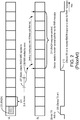
- FIG. 2 is a signal timing diagram of a conventional Random Access procedure such as is used in a conventional LTE (or comparable) system.
- the air interface is divided up into sequentially occurring sub-frames, of which the sub-frame 201 is but one example. It is assumed in this illustration that the mobile device has already synchronized itself to the network node.
- uplink (UL - from device to network node) and downlink (DL - from network node to device) timelines are shown separate and aligned with one another.
- the device transmits a random access signal on a RACH channel 203, indicating that it intends to get in contact with the network node for the purpose of, for example, transmitting data information.
- the RACH is typically allocated a certain frequency bandwidth in one or more sub-frames.
- the RACH 203 fits within a single sub-frame.
- the RACH is of shorter duration than an entire sub-frame in order to cope with the fact that, at the time of the device's initial contact with the network node, the travel distance (and hence path delay) of the radio signal between the network node and the device is unknown.
- the device turns on its transmitter (device activation step 205) and transmits the specific RACH signature (previously provided by the network node) that identifies the terminal to the network node.
- the network node detects the RACH signal some number of sub-frames later (step 207) and in response, transmits an RAR signal to the device (step 209), indicating procedures for further communication.
- a RACH response window 211 is defined.
- the network node's RAR signal can be transmitted to the device in any one of the sub-frames spanned by the RACH window 211
- the RAR window 211, signaled (or broadcasted) from the network node is typically 5-10 sub-frames in duration, and hence the device needs to have the receiver (RX) on during the entire RAR window for monitoring of the RAR (device activation step 213).
- the long receiver "on" time relative to the short RAR information that is to be captured (a ratio that is on the order of 5-10 to 1), it is apparent that this is not a good solution.
- Controlling access by a User Equipment (UE) to a cellular network may be effected by: receiving an instruction at the UE from a base station of the cellular network regarding transmission by the UE over a Random Access Channel (RACH) of the cellular network; and controlling when transmissions are made from the UE over the RACH, on the basis of the received instruction.
- RACH Random Access Channel
- a transmission over the RACH may be made in response to the received instruction, which gives permission for the UE to transmit if it has data to send.
- the instruction specifies a Group Identifier, which is compared with a Group Identifier specific to the UE and transmission over the RACH may be avoided based on the comparison.
- the UE may be a Machine Type Communication device.
- Bandwidth reduction for low cost MTC UE and text proposal (3GPP DRAFT; R1-120051 concerns Bandwidth reduction for low cost MTC UE (Machine Type Communication device) and discusses the necessity of the bandwidth reduction for this kind of device.
- a narrowband PDCCH for the RAR Random Access Response
- the RAR is to be scheduled within this narrowband PDCCH.
- the foregoing and other objects are achieved in, for example, methods and apparatuses for operating a network node that serves a cell in a cellular communication system, wherein an air interface of the cellular communication system is divided up into sequentially occurring frames, each of the frames comprising a plurality of sequentially occurring sub-frames, each of the sub-frames comprising a plurality of sequentially occurring symbols.
- Such operation includes: receiving information from a device indicative of one or more device capabilities of the device, ascertaining a suitable RACH signature and corresponding RAR signal reception information, including relative time/frequency grid position at which a RAR signal will be transmitted when the device uses the RACH signature in a random access request; transmitting information to the device, wherein the information is indicative of the RACH signature of the RACH request signal that is indicative of one or more device capabilities; receiving and detecting a RACH request signal transmitted by the device within the cell. Based at least in part on a RACH signature of the request signal that is indicative of one or more device capabilities of the device, an associated time/frequency position and RAR window size for transmitting a response signal is ascertained. The response signal is then transmitted at the ascertained time/frequency position.
- the response signal consists of fewer symbols than are contained in a sub-frame.
- the number of symbols can, in some instances, be as few as one.
- the response signal consists of a number of symbols that is less than a total number of symbols contained within a sub-frame and that is a function of the characteristic of the request signal that is indicative of one or more device capabilities of the device.
- a frequency-wise spread of the associated time/frequency position for transmitting the response signal is less than a frequency-wise spread of a symbol.
- each of the symbols is an Orthogonal Frequency Division Multiplexing (OFDM) symbol.
- OFDM Orthogonal Frequency Division Multiplexing
- operation includes controlling a scheduler of the network node based on the associated time/frequency position for transmitting the response signal.
- methods and apparatuses are provided for operating a device in a cellular communication system having a network node, wherein an air interface of the cellular communication system is divided up into sequentially occurring frames, each of the frames comprising a plurality of sequentially occurring sub-frames, each of the sub-frames comprising a plurality of sequentially occurring symbols.
- Such operation includes communicating device capability information to the network node and then subsequently receiving information comprising a suitable RACH signature and corresponding RAR signal reception information, including relative time/frequency grid position and RAR window size at which a RAR signal will be transmitted, that is indicative of a request procedure and a response procedure to be used by the device when making a request and subsequently monitoring for a request response.
- a RACH request is transmitted to the network node based on the received information that is indicative of the request procedure, and received signals are monitored to detect a random access response signal in accordance with the information that is indicative of the response procedure.
- the response procedure indicates a duration of a response window that is shorter than a duration of a sub-frame.
- circuitry configured to perform one or more described actions is used herein to refer to any such embodiment (i.e., one or more specialized circuits and/or one or more programmed processors).
- the invention can additionally be considered to be embodied entirely within any form of computer readable carrier, such as solid-state memory, magnetic disk, or optical disk containing an appropriate set of computer instructions that would cause a processor to carry out the techniques described herein.
- any such form of embodiments as described above may be referred to herein as "logic configured to” perform a described action, or alternatively as “logic that” performs a described action.
- a network node that serves a cell in a cellular communication system transmits a response signal responsive to an access request signal received from an MTC device, wherein the cellular communication system is primarily designed to support mobile broadband use, not MTC use.
- the network's response signal is transmitted at a very specific time/frequency position, with the time/frequency position being a function of the device's access request signal signature.
- the time/frequency position occupied by the network node's response signal is of shorter duration than an entire sub-frame.
- the network node's response signal could occupy just a single one of these symbols (e.g., in an LTE system, just one symbol out of a possible 12-14 OFDM symbols that make up one sub-frame).
- the (subset of) symbol(s) need not be dedicated wholly for use by the network node's response signal.
- the symbol (or possibly more than one in some embodiments) which is defined as spanning some bandwidth of radio frequency spectrum, can be configured such that only a frequency-wise portion of the symbol's entire bandwidth is used for communicating the network node's response signal.
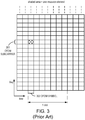
- the LTE physical layer downlink transmission is based on OFDM.
- the basic LTE downlink physical resource can thus be seen as a time-frequency grid as illustrated in FIG. 3 , in which each so-called “resource element” corresponds to one OFDM subcarrier during one OFDM symbol interval.
- each so-called “resource element” corresponds to one OFDM subcarrier during one OFDM symbol interval.
- the intersection of OFDM subcarrier 301 and OFDM symbol 303 is an exemplary resource element (illustrated in cross-hatching).
- the downlink subcarriers in the frequency domain are grouped into resource blocks (RBs), where each resource block consists of twelve subcarriers for a duration of one 0.5 ms slot (7 OFDM symbols when normal cyclic prefixes are used (as illustrated) or 6 OFDM symbols when extended cyclic prefixes are used), corresponding to a nominal resource-block bandwidth of 180 kHz.
- RBs resource blocks
- the total number of downlink subcarriers, including a DC-subcarrier, thus equals N c 12 ⁇ N RB +1 where N RB is the maximum number of resource blocks that can be formed from the 12 ⁇ N RB usable subcarriers.
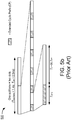
- FIGS. 5a and 5b illustrate the time-domain structure for LTE downlink transmission.
- Each slot then consists of a number of OFDM symbols.
- the overall OFDM symbol time is then the sum of the useful symbol time and the cyclic prefix length T CP .
- Two cyclic prefix lengths are defined.
- FIG. 5a illustrates a normal cyclic prefix length, which allows seven OFDM symbols per slot to be communicated.
- the length of a normal cyclic prefix, T CP is 160 T S ⁇ 5.1 ⁇ s for the first OFDM symbol of the slot, and 144 ⁇ T S ⁇ 4.7 ⁇ s for the remaining OFDM symbols.
- FIG. 5b illustrates an extended cyclic prefix, which because of its longer size, allows only six OFDM symbols per slot to be communicated.
- the length of an extended cyclic prefix, T CP - e is 512 ⁇ T S ⁇ 16.7 ⁇ s.
- the cyclic prefix length for the first OFDM symbol of a slot is somewhat larger than those for the remaining OFDM symbols. The reason for this is simply to fill out the entire 0.5 ms slot, as the number of time units per slot, T S , (15360) is not evenly divisible by seven.
- Cell search is the procedure by which the terminal finds a cell to which it can potentially connect. As part of the cell search procedure, the terminal obtains the identity of the cell and estimates the frame timing of the identified cell. The cell search procedure also provides estimates of parameters essential for reception of system information (SI) on the broadcast channel, containing the remaining parameters required for accessing the system.
- SI system information
- the number of physical layer cell identities should be sufficiently large.
- systems in accordance with the LTE standards support 504 different cell identities. These 504 different cell identities are divided into 168 groups of three identities each.
- LTE provides a primary synchronization signal and a secondary synchronization signal on the downlink.
- FIG. 6 shows the structure of the radio interface of an LTE system.
- the physical layer of an LTE system includes a generic radio frame 600 having a duration of 10ms.
- FIG. 6 illustrates one such frame 600 for an LTE Frequency Division Duplex (FDD) system.
- FDD Frequency Division Duplex
- a sub-frame is made up of two adjacent slots, and therefore has a duration of 1 ms, normally consisting of 14 OFDM symbols.
- the primary and secondary synchronization signals are specific sequences, inserted into the last two OFDM symbols in the first slot of each of subframes 0 and 5.
- the primary synchronization signal can occupy less bandwidth than does the secondary synchronization signal.
- part of the operation of the cell search procedure also exploits reference signals that are transmitted at known locations in the transmitted signal.
- FIG. 7 illustrates a network node 701 that is operated in accordance with some aspects of the invention so as to provide improved performance for a low cost/low power communication device (e.g., an MTC device) 703 while continuing to serve a (e.g., legacy) user equipment 705.
- a low cost/low power communication device e.g., an MTC device
- Each of these random access requests has its own signature to identify the device.
- the low cost/low power communication device has its own associated random access signature (represented in the figure by "RACH 1 ")
- the user equipment's random access request has its associated random access signature (represented in the figure by "RACH 2 ").
- the network node 701 uses the signature as a basis for ascertaining a time and frequency during which the responding RAR will be transmitted. It will be understood that there may, but need not be, other bases that are additionally used. Accordingly, the RAR that the network node 701 transmits in response to receipt of the RACH 1 signature occupies a time/frequency ("t/f') location that is at least in part a function of RACH 1 . Similarly, the RAR that the network node 701 transmits in response to receipt of the RACH 2 signature occupies a time/frequency location that is at least in part a function of RACH 2 .
- FIG. 8 is a signal timing diagram of a Random Access procedure in accordance with exemplary embodiments that are consistent with the invention.
- the air interface is divided up into sequentially occurring sub-frames, of which the sub-frame 801 is but one example. It is assumed in this illustration that the mobile device has already synchronized itself to the network node.
- uplink (UL - from device to network node) and downlink (DL - from network node to device) timelines are shown separate and aligned with one another.
- the device transmits a random access signal on a RACH channel 803, indicating that it intends to get in contact with the network node for the purpose of, for example, transmitting data information.
- the RACH is typically allocated a certain frequency bandwidth in one or more sub-frames.
- the RACH 803 fits within a single sub-frame.
- the RACH is of shorter duration than an entire sub-frame in order to cope with the fact that, at the time of the device's initial contact with the network node, the travel distance (and hence path delay) of the radio signal between the network node and the device is unknown.
- the device turns on its transmitter (device activation step 805) and transmits the specific RACH signature (previously provided by the network node) that identifies the terminal to the network node.
- the network node detects the RACH signal some number of sub-frames later (step 807) and in response, ascertains a time/frequency ("t/f") position preferably within (i.e., smaller than) a sub-frame at which the device will be able to detect the RAR.
- t/f time/frequency
- the network node transmits the RAR signal to the device (step 809), indicating procedures for further communication.
- the device knows, either by standardization or alternatively by means of earlier signaling between the network node and the device, what the RAR signal's time/frequency position will be. Accordingly, The RACH window 811 is very small. Accordingly, the device needs to have the receiver (RX) on only for a sufficient amount of time (device activation step 213) to be able to receive the RAR signal at the expected time.
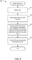
- FIG. 9 is, in one respect, a flow chart of steps/processes performed by a communication system node in accordance with some but not necessarily all exemplary embodiments of the invention.
- FIG. 9 can be considered to depict exemplary means 900 comprising the various illustrated circuitry (e.g., hard-wired and/or suitably programmed processor) configured to perform the described functions.
- the network node listens for the presence of Random Access signals in sub-frames allocated to the RACH in the uplink (step 901). Once a RACH signal is detected, the specific RACH signature is decoded/detected (step 903). Next, a mapping is performed whereby the detected signature is used as at least one basis by which the network node ascertains a certain time/frequency grid location where the RAR signal should be transmitted (step 905). Other bases that can (but need not) be used in conjunction with detected signature for the purpose of ascertaining the certain time/frequency grid location where the RAR signal should be transmitted include, without limitation, the frequency and/or time position of the received Random Access signals.
- mapping function is predefined either by standardization (so that the requesting device also able to ascertain by itself what the mapping will be) or by earlier signaling between the network node and the device (in which case the device has previously been informed by the network node what the mapping would be).
- Means for mapping are exemplified by, without limitation, a look up table, or alternatively circuitry (e.g., suitably programmed processor or a dedicated hardware circuitry configuration or a combination of both) that ascertains a function of the RACH signature (plus any other parameters that may be involved).
- a function could be, for example and without limitation, based on a signature index.
- the spread in time and frequency can be uniform, or alternatively can be different for different signatures.
- some signatures may correspond to devices that require only one OFDM symbol in time, while other signatures may correspond to devices that require more than one but less than all of the OFDM symbols in a sub-frame.
- the time spread (and in some embodiments also the frequency spread) could be different in dependence on the amount of information that is needed to be transmitted in the RAR signal.
- some RACH signatures may correspond to devices that require a longer delay in time prior to RAR signal transmission than other devices.
- the time position (relative to the RACH timing) of the RAR signal transmission can be adapted based at least partly on the detected RACH signature.
- the network node Having mapped the received RACH signature to a time/frequency position, the network node then transmits the RAR signal at the ascertained time/frequency position (step 907).
- FIG. 10 is, in one respect, a flow chart of steps/processes performed by a communication system node in accordance with some but not necessarily all exemplary embodiments of the invention.
- FIG. 10 can be considered to depict exemplary means 1000 comprising the various illustrated circuitry (e.g., hard-wired and/or suitably programmed processor) configured to perform the described functions.
- FIG. 10 illustrates an exemplary embodiment of how a RACH signature can be allocated.
- the device makes a first connection to the network node (step 1001).
- This connection can be made by any standardized RACH procedure, without any need to focus on optimized power consumption and/or spectral efficiency. Accordingly, any conventional initial connection technique can be used for this step. Techniques for making such initial connections are described in, for example and without limitation, U.S. Patent Application Number 13/398,786, filed on February 16, 2012 (Joakim Axmon et al. , "Cellular Communication System Support for Limited Bandwidth Communication Devices") and U.S. Patent Application Number 13/398,787, filed on February 16, 2012 (Joakim Axmon et al. , "Cellular Communication System Support for Limited Bandwidth Communication Devices"). As a result of this initial connection, the network node is informed about the device's capability (step 1003).
- a suitable RACH signature and corresponding RAR signal reception information e.g., relative time/frequency grid position at which a RAR signal will be transmitted whenever the device uses the RACH signature in a random access request.
- the RAR window can be chosen to be large in order to permit the network node to prioritize flexibility in its scheduler for optimized spectral efficiency/capacity.
- Such a RAR window could, for example, resemble the RAR window 211 illustrated in FIG. 2 .
- the conventional techniques always use the RAR window 211 regardless of the device's capabilities, in this instance such a window will have been arrived at only in response to a consideration of the device's capabilities.
- RACH signatures and associated RAR signaling techniques that result in a RAR window such as the RAR window 813 depicted in FIG. 8 .
- some device capabilities might require that the RAR signal be transmitted shortly after the RACH signal is received by the network node. Devices with such capabilities will be assigned RACH signatures with associated RAR signaling occurring, for example, only some few milliseconds (4-10 ms) after the RACH signal. This might impact the scheduler flexibility (capacity) and therefore such MTC capabilities are typically "high end" sensors where fast response and information transfer is needed (e.g., vehicle applications).
- RAR window 811 depicted in FIG. 8 Other capabilities need the new RAR having the short RAR window (e.g., the RAR window 811 depicted in FIG. 8 ) and find it acceptable for the RAR signal to be transmitted after a large delay. Permitting a long delay gives the network node's scheduler a long time to prepare in advance for the RAR signal transmission, so that the impact of this transmission on the network node's data handling capacity can be very limited.
- These devices e.g., battery driven sensors gathering non-time critical information
- the information about the RACH signature and its associated RAR response information is transmitted in a message (for instance via Radio Resource Control -- "RRC" -- signaling) to the device (1007).
- FIG. 11 is a block diagram of system elements for carrying out the various aspects of the invention.
- a network node 1101 e.g., an eNodeB configured to be capable of carrying out the functionality described above
- a transceiver 1103 that can send and receive signals for serving a variety of devices, such as conventional user equipment (e.g., broadband communication devices) as well as limited capability/bandwidth devices (e.g., MTC devices such as sensors) as described above.
- the network node 1101 includes circuitry configured to carry out any one or any combination of the random access aspects described above with respect to actions taken by the node.
- Such circuitry could, for example, be entirely hard-wired circuitry (e.g., one or more Application Specific Integrated Circuits - "ASICs").
- ASICs Application Specific Integrated Circuits - "ASICs”
- programmable circuitry comprising a processor 1105 coupled to one or more memory devices 1107 (e.g., Random Access Memory, Magnetic Disc Drives, Optical Disk Drives, Read Only Memory, etc.) and to a network interface 1109.
- the memory device(s) 1107 store program means 1111 (e.g., a set of processor instructions) configured to cause the processor 1105 to control other node elements so as to carry out any of the node-related aspects described above.
- the memory device(s) 1107 may also store data (not shown) representing various constant and variable parameters as may be needed by the processor 1105 when carrying out its functions such as those specified by the program means 1111.
- the network interface 1109 allows the node 1101 to communicate with other nodes (not shown) in the communication system.
- FIG. 12 is a block diagram of a communication device 1201 (e.g., and without limitation, a low cost/low power communication device, such as an MTC device as used in examples described above).
- the communication device 1201 includes a controller 1203 coupled to other User Equipment (UE) circuitry/hardware components 1205 that enable the communication device 1201 to perform its application-specific functionality (e.g., operating as a broadband communication device, operating as a sensor of some sort, etc.) and also to operate as a communication device (e.g., to be able to communicate information such as but not limited to sensor data to a server, and possibly also to receive instructions).
- UE User Equipment
- the other UE circuitry/hardware components 1205 are generally known in the art, and may include such elements as, for example and without limitation, radio circuitry 1207 coupled to one or more antennas 1209, and (optionally) sensor circuitry 1211 (e.g., temperature sensor, acoustical sensor, magnetic field sensor, etc.).
- the other UE circuitry/hardware may also include some sort of user interface (e.g., display, keyboard, switch(es)) 1213, although applications that call for use of a low cost/low power communication device may have very simplistic needs for a user interface 1213 (e.g., a reset switch) or none at all.
- the controller 1203 includes circuitry configured to carry out any one or any combination of the random access aspects described above with respect to device actions. Such circuitry could, for example, be entirely hard-wired circuitry (e.g., one or more ASICs). Depicted in the exemplary embodiment of FIG. 12 , however, is programmable circuitry, comprising a processor 1215 coupled to one or more memory devices 1217 (e.g., Random Access Memory, Magnetic Disc Drives, Optical Disk Drives, Read Only Memory, etc.).
- the memory device(s) store program means 1219 (e.g., a set of processor instructions) configured to cause the processor 1215 to control the other UE circuitry/hardware components 1205 so as to carry out any of the device-related aspects described above.
- the memory 1217 may also store data 1221 representing various constant and variable parameters as may be needed by the processor 1215 when carrying out its functions such as those specified by the program means 1219.
- FIG. 13 is, in one respect, a flow chart of steps/processes performed by a communication device (e.g., a broadband communication device or a low cost/low power device such as but not limited to an MTC device) in accordance with some but not necessarily all exemplary embodiments of the invention.
- a communication device e.g., a broadband communication device or a low cost/low power device such as but not limited to an MTC device
- FIG. 13 can be considered to depict exemplary means 1300 comprising the various illustrated circuitry (e.g., hard-wired and/or suitably programmed processor) configured to perform the described functions.
- the device communicates its relevant capabilities to the network node (step 1301).
- a capability is "relevant" to the RACH procedure if it will be used by the node to tailor its RAR signaling (e.g., to determine a time/frequency at which the RAR will be transmitted, and/or to determine the width of the RAR signal, for example as measured in number of symbols).
- whether the device has a wired or battery-driven power supply can be used as one basis for determining the size of the RAR window; the device's processing speed may be used as one basis for determining how quickly the device needs to receive the RAR signal after the RACH signal (or alternatively, how much delay the device needs before it is capable of monitoring for the RAR signal after transmitting a RACH signal).
- the device then receives, in response, information that is indicative (either directly or indirectly) of the RACH (e.g., what RACH signature to use) and of the RAR signaling procedure (e.g., time/frequency at which the RAR will be transmitted in response to a RACH signal being received by the node, and/or the width of the RAR signal) (step 1303).
- information that is indicative (either directly or indirectly) of the RACH e.g., what RACH signature to use
- the RAR signaling procedure e.g., time/frequency at which the RAR will be transmitted in response to a RACH signal being received by the node, and/or the width of the RAR signal
- the device when it wants to contact the network node, it transmits a RACH signal using the RACH signature that had been earlier received (step 1305).
- the device then monitors the RAR window whose time/frequency position (and in some embodiments also duration) was defined by the information received from the network node (step 1307).
- One benefit of the random access techniques as described herein is that the amount of time that a device's receiver needs to be turned on for reception of access response signals can be minimized, thereby minimizing the device's power consumption associated with this operation.
Claims (18)
- Procédé de fonctionnement d'un noeud de réseau (1101) qui dessert une cellule (103) dans un système de communication cellulaire, dans lequel une interface hertzienne du système de communication cellulaire est divisée en trames survenant de manière séquentielle (600), chacune des trames (600) comprenant une pluralité de sous-trames survenant de manière séquentielle (500), chacune des sous-trames comprenant une pluralité de symboles survenant de manière séquentielle (303), le procédé étant caractérisé en ce qu'il comprend :la réception (1003) d'informations d'un dispositif indiquant une ou plusieurs capacités du dispositif,la détermination d'une signature RACH appropriée et d'informations de signal RAR correspondantes, y compris la position de grille de temps/fréquence relative à laquelle un signal RAR sera transmis lorsque le dispositif utilise la signature RACH dans une requête d'accès aléatoire (1005) ;la transmission (1007) des informations au dispositif, les informations indiquant la signature RACH du signal de requête RACH qui indique une ou plusieurs capacités du dispositif ;la réception et la détection (903) d'un signal de requête RACH (RACH1, RACH2) transmis par le dispositif (703, 705) à l'intérieur de la cellule (103) ;sur la base au moins en partie d'une signature RACH du signal de requête qui indique une ou plusieurs capacités de dispositif du dispositif, la détermination (807, 905) d'une position de temps/fréquence associée et d'une taille de fenêtre RAR (811) pour transmettre un signal de réponse ; etla transmission (809, 907) du signal de réponse à la position de temps/fréquence (811) déterminée.
- Procédé selon la revendication 1, dans lequel le signal de réponse est constitué de moins de symboles (303) que ceux contenus dans une sous-trame (500).
- Procédé selon l'une quelconque des revendications 1 ou 2, dans lequel un étalement en fréquence de la position de temps/fréquence (811) associée pour transmettre le signal de réponse est inférieur à un étalement en fréquence d'un symbole (303).
- Procédé selon l'une quelconque des revendications précédentes, dans lequel chacun des symboles (303) est un symbole de multiplexage par répartition orthogonale de la fréquence (OFDM).
- Procédé selon l'une quelconque des revendications précédentes, dans lequel le signal de réponse est constitué d'un seul symbole (303).
- Procédé selon l'une quelconque des revendications 1 à 5, dans lequel le signal de réponse est constitué d'un nombre de symboles (303) qui est inférieur à un nombre total de symboles (303) contenu à l'intérieur d'une sous-trame (500) et qui est une fonction de la caractéristique du signal de requête qui indique une ou plusieurs capacités de dispositif du dispositif.
- Procédé selon l'une quelconque des revendications précédentes, comprenant :le contrôle d'un planificateur du noeud de réseau sur la base de la position de temps/fréquence (811) associée pour transmettre le signal de réponse.
- Procédé d'utilisation d'un dispositif (703, 705) dans un système de communication cellulaire ayant un noeud de réseau (1101), dans lequel une interface hertzienne du système de communication cellulaire est divisée en trames survenant de manière séquentielle (600), chacune des trames (600) comprenant une pluralité de sous-trames survenant de manière séquentielle (500), chacune des sous-trames comprenant une pluralité de symboles survenant de manière séquentielle (303), le procédé étant caractérisé en ce qu'il comprend :la communication (1301) d'informations de capacité de dispositif au noeud de réseau (1101) ;la réception (1303) d'informations comprenant une signature RACH appropriée et d'informations de réception de signal RAR correspondantes, y compris la position de grille de temps/fréquence relative et la taille de la fenêtre RAR (811) à laquelle un signal RAR sera transmis, qui indique une procédure de requête et une procédure de réponse à utiliser par le dispositif lors de la réalisation d'une requête et de la surveillance consécutive pour une réponse de requête ;la transmission d'une requête RACH (1305) au noeud de réseau (1101) sur la base des informations reçues qui indiquent la procédure de requête ; etla surveillance (1307) des signaux reçus pour détecter un signal de réponse d'accès aléatoire selon les informations qui indiquent la procédure de réponse.
- Procédé selon la revendication 8, dans lequel la procédure de réponse indique une durée d'une fenêtre de réponse qui est plus courte qu'une durée d'une sous-trame (500).
- Appareil (1105, 1107, 1111) d'utilisation d'un noeud de réseau (1101) qui dessert une cellule (103) dans un système de communication cellulaire, dans lequel une interface hertzienne du système de communication cellulaire est divisée en trames survenant de manière séquentielle (600), chacune des trames (600) comprenant une pluralité de sous-trames survenant de manière séquentielle (500), chacune des sous-trames comprenant une pluralité de symboles survenant de manière séquentielle (303), l'appareil étant caractérisé en ce qu'il comprend :un ensemble de circuits configuré pour recevoir (1003) des informations d'un dispositif indiquant une ou plusieurs capacités du dispositif,un ensemble de circuits configuré pour déterminer une signature RACH appropriée et des informations de réception de signal RAR correspondantes, y compris la position de grille de temps/fréquence relative à laquelle un signal RAR sera transmis lorsque le dispositif utilise la signature RACH dans une requête d'accès aléatoire (1005) ;un ensemble de circuits pour transmettre (1007) des informations au dispositif, les informations indiquant la signature RACH du signal de requête RACH qui indique une ou plusieurs capacités du dispositif ;un ensemble de circuits configuré pour recevoir et détecter (903) un signal de requête RACH (RACH1, RACH2) transmis par le dispositif (703, 705) à l'intérieur de la cellule (103) ;un ensemble de circuits configuré pour déterminer (807, 905) sur la base au moins en partie d'une signature RACH du signal de requête qui indique une ou plusieurs capacités de dispositif du dispositif, une position de temps/fréquence associée et une taille de fenêtre RAR (811) pour transmettre un signal de réponse ; etun ensemble de circuits configuré pour transmettre (809, 907) le signal de réponse à la position de temps/fréquence (811) déterminée.
- Appareil (1105, 1107, 1111) selon la revendication 10, dans lequel le signal de réponse est constitué de moins de symboles (303) que ceux contenus dans une sous-trame (500).
- Appareil (1105, 1107, 1111) selon la revendication 10 ou 11, dans lequel un étalement en fréquence de la position de temps/fréquence associée (811) pour transmettre le signal de réponse est inférieur à un étalement en fréquence d'un symbole (303).
- Appareil (1105, 1107, 1111) selon l'une quelconque des revendications 10 à 12, dans lequel chacun des symboles (303) est un symbole de multiplexage par répartition orthogonale de la fréquence (OFDM).
- Appareil (1105, 1107, 1111) selon l'une quelconque des revendications 10 à 13, dans lequel le signal de réponse est constitué d'un seul symbole (303).
- Appareil (1105, 1107, 1111) selon l'une quelconque des revendications 10 à 13, dans lequel le signal de réponse est constitué d'un nombre de symboles (303) qui est inférieur à un nombre total de symboles (303) contenu à l'intérieur d'une sous-trame (500) et qui est une fonction de la caractéristique du signal de requête qui indique une ou plusieurs capacités de dispositif du dispositif.
- Appareil (1105, 1107, 1111) selon l'une quelconque des revendications 10 à 15, comprenant :un ensemble de circuits configuré pour contrôler un planificateur du noeud de réseau sur la base de la position de temps/fréquence associée (811) pour transmettre le signal de réponse.
- Appareil (1203) d'utilisation d'un dispositif (703, 705) dans un système de communication cellulaire ayant un noeud de réseau (1101), dans lequel une interface hertzienne du système de communication cellulaire est divisée en trames survenant de manière séquentielle (600), chacune des trames (600) comprenant une pluralité de sous-trames survenant de manière séquentielle (500), chacune des sous-trames comprenant une pluralité de symboles survenant de manière séquentielle (303), l'appareil étant caractérisé en ce qu'il comprend :un ensemble de circuits configurés pour communiquer (1301) des informations de capacité de dispositif au noeud de réseau (1101) ;un ensemble de circuits configurés pour recevoir (1303) des informations comprenant une signature RACH appropriée et des informations de réception de signal RAR correspondantes, y compris la position de grille de temps/fréquence relative et la taille de la fenêtre RAR (811) à laquelle un signal RAR sera transmis, qui indique une procédure de requête et une procédure de réponse à utiliser par le dispositif lors de la réalisation d'une requête et de la surveillance consécutive pour une réponse de requête ;un ensemble de circuits configurée pour transmettre une requête RACH (1305) au noeud de réseau (1101) sur la base des informations reçues qui indiquent la procédure de requête ; etun ensemble de circuits configuré pour surveiller (1307) les signaux reçus pour détecter un signal de réponse d'accès aléatoire selon les informations qui indiquent la procédure de réponse.
- Appareil (1203) selon la revendication 17, dans lequel la procédure de réponse indique une durée d'une fenêtre de réponse qui est plus courte qu'une durée d'une sous-trame (500).
Applications Claiming Priority (2)
| Application Number | Priority Date | Filing Date | Title |
|---|---|---|---|
| US13/411,008 US9332570B2 (en) | 2012-03-02 | 2012-03-02 | Access response signaling in a cellular communication system |
| PCT/EP2013/053708 WO2013127736A1 (fr) | 2012-03-02 | 2013-02-25 | Signalisation de réponse d'accès dans un système de communication cellulaire |
Publications (2)
| Publication Number | Publication Date |
|---|---|
| EP2820908A1 EP2820908A1 (fr) | 2015-01-07 |
| EP2820908B1 true EP2820908B1 (fr) | 2018-04-11 |
Family
ID=47748640
Family Applications (1)
| Application Number | Title | Priority Date | Filing Date |
|---|---|---|---|
| EP13705803.8A Active EP2820908B1 (fr) | 2012-03-02 | 2013-02-25 | Signalisation de réponse d'accès dans un système de communication cellulaire |
Country Status (7)
| Country | Link |
|---|---|
| US (1) | US9332570B2 (fr) |
| EP (1) | EP2820908B1 (fr) |
| AR (1) | AR090222A1 (fr) |
| IN (1) | IN2014DN05629A (fr) |
| RU (1) | RU2636684C2 (fr) |
| WO (1) | WO2013127736A1 (fr) |
| ZA (1) | ZA201405130B (fr) |
Families Citing this family (7)
| Publication number | Priority date | Publication date | Assignee | Title |
|---|---|---|---|---|
| GB2502274B (en) * | 2012-05-21 | 2017-04-19 | Sony Corp | Telecommunications systems and methods |
| KR20160044469A (ko) * | 2013-08-14 | 2016-04-25 | 소니 주식회사 | 상향링크 공유 채널에서의 전력 밀도 부스팅 |
| WO2016048045A1 (fr) | 2014-09-23 | 2016-03-31 | Lg Electronics Inc. | Procédé et appareil de signalisation de sous-trames de liaison descendante utilisables, pour un équipement d'utilisateur économique dans un système de communications sans fil |
| US10555345B2 (en) | 2015-01-30 | 2020-02-04 | Qualcomm Incorporated | Random access procedure and broadcast prioritization for machine type communications (MTC) |
| EP3661301B1 (fr) * | 2015-02-12 | 2023-06-21 | Huawei Technologies Co., Ltd. | Appareil, système et procédé de transmission de signal |
| US11388754B2 (en) | 2016-06-06 | 2022-07-12 | Qualcomm Incorporated | Channel state information reporting for random access procedures |
| CN115001631B (zh) * | 2018-09-28 | 2024-04-05 | 苹果公司 | 新无线电车辆到一切(v2x)通信中的改进的组播和单播 |
Family Cites Families (17)
| Publication number | Priority date | Publication date | Assignee | Title |
|---|---|---|---|---|
| US6072784A (en) * | 1997-07-25 | 2000-06-06 | At&T Corp. | CDMA mobile station wireless transmission power management with adaptive scheduling priorities based on battery power level |
| US8169944B2 (en) * | 2002-10-25 | 2012-05-01 | Qualcomm Incorporated | Random access for wireless multiple-access communication systems |
| US7212809B2 (en) * | 2003-02-06 | 2007-05-01 | Motorola, Inc. | Method and apparatus for service negotiation acceleration |
| US8787350B2 (en) * | 2005-12-07 | 2014-07-22 | Meshnetworks, Inc. | System and method to facilitate the use of multiple radios to increase the capacity of a wireless communication network |
| RU2421911C2 (ru) * | 2005-12-23 | 2011-06-20 | Эл Джи Электроникс Инк. | Способ и процедуры несинхронизированной связи, синхронизированной связи и синхронизации связи в режиме ожидания "stand-by" и в системах e-utra |
| US8369860B2 (en) * | 2006-08-18 | 2013-02-05 | Interdigital Technology Corporation | Sending and reducing uplink feedback signaling for transmission of MBMS data |
| US8422439B2 (en) * | 2008-12-31 | 2013-04-16 | Motorola Mobility Llc | Apparatus and method for communicating control information over a data channel in the absence of user data |
| WO2010087569A1 (fr) * | 2009-02-02 | 2010-08-05 | Lg Electronics Inc. | Détermination de capacité d'antenne d'équipement utilisateur |
| US20100284346A1 (en) * | 2009-05-11 | 2010-11-11 | Rudrapatna Ashok N | System and method for cell-edge performance management in wireless systems using centralized scheduling |
| US8897241B2 (en) * | 2009-10-14 | 2014-11-25 | Lg Electronics Inc. | Radio resource allocation |
| US9253798B2 (en) | 2010-02-12 | 2016-02-02 | Interdigital Patent Holdings, Inc. | Method and apparatus for optimizing uplink random access channel transmission |
| US8204507B2 (en) * | 2010-03-12 | 2012-06-19 | Research In Motion Limited | Supplemental node transmission assistance in a wireless communications network |
| US8462722B2 (en) | 2010-03-26 | 2013-06-11 | Telefonaktiebolaget L M Ericsson (Publ) | Access control for machine-type communication devices |
| EP2369890A1 (fr) | 2010-03-26 | 2011-09-28 | Panasonic Corporation | Évitement de pic de connexion pour dispositifs de communication de type machine |
| GB201005312D0 (en) | 2010-03-30 | 2010-05-12 | Vodafone Ip Licensing Ltd | Device and method of operation |
| US20110317636A1 (en) | 2010-06-24 | 2011-12-29 | John Diachina | Channel requests for machine-type devices |
| US20120281530A1 (en) * | 2010-11-08 | 2012-11-08 | Qualcomm Incorporated | System and method for radio access network overload control |
-
2012
- 2012-03-02 US US13/411,008 patent/US9332570B2/en active Active
-
2013
- 2013-02-25 RU RU2014139843A patent/RU2636684C2/ru active
- 2013-02-25 IN IN5629DEN2014 patent/IN2014DN05629A/en unknown
- 2013-02-25 EP EP13705803.8A patent/EP2820908B1/fr active Active
- 2013-02-25 WO PCT/EP2013/053708 patent/WO2013127736A1/fr active Application Filing
- 2013-03-01 AR ARP130100683A patent/AR090222A1/es active IP Right Grant
-
2014
- 2014-07-14 ZA ZA2014/05130A patent/ZA201405130B/en unknown
Also Published As
| Publication number | Publication date |
|---|---|
| IN2014DN05629A (fr) | 2015-04-03 |
| WO2013127736A1 (fr) | 2013-09-06 |
| RU2014139843A (ru) | 2016-04-20 |
| AR090222A1 (es) | 2014-10-29 |
| US20130230016A1 (en) | 2013-09-05 |
| EP2820908A1 (fr) | 2015-01-07 |
| ZA201405130B (en) | 2017-06-28 |
| US9332570B2 (en) | 2016-05-03 |
| RU2636684C2 (ru) | 2017-11-27 |
Similar Documents
| Publication | Publication Date | Title |
|---|---|---|
| JP6743209B2 (ja) | モバイル端末および方法 | |
| KR102040167B1 (ko) | 무선 시스템용 시그널링 구성 | |
| EP3058676B1 (fr) | Indicateur de format de commande de liaison descendante | |
| JP5964421B2 (ja) | 帯域幅制限のある通信デバイスに対するセルラー通信システムサポート | |
| EP3096481B1 (fr) | Procédé et appareil de transmission de signal | |
| EP3169100B1 (fr) | Procédé et appareil permettant de déterminer la configuration ul-dl tdd applicable pour des trames radio | |
| CN108781431B (zh) | 用于针对发现信号传输调度寻呼消息的网络节点、方法和计算机程序产品 | |
| EP3539342B1 (fr) | Réduction de latence dans un spectre partagé ou sans licence | |
| EP2724565B1 (fr) | Prise en charge de système de communication cellulaire pour dispositifs de communication à largeur de bande limitée | |
| KR102142739B1 (ko) | 감소된 대역폭 단말기들에의 제어 정보의 전송 | |
| EP2820908B1 (fr) | Signalisation de réponse d'accès dans un système de communication cellulaire | |
| US9408211B2 (en) | Method and apparatus for resource management, low-bandwidth user equipment, and user equipment | |
| US20180192321A1 (en) | Reference Signal In A Communications Network | |
| US10542492B2 (en) | Method for DRX in unlicensed band, and device using same | |
| US10681623B2 (en) | Methods and apparatus for cell access via anchor carrier | |
| KR20150110540A (ko) | 머신형 통신을 위한 가상 캐리어들 간에 시스템 정보를 할당하는 이동 통신 장비 및 방법 | |
| CN115211219A (zh) | 无线通信系统中降低能力的用户设备的随机接入方法和装置 | |
| CN113303018A (zh) | 用于无需许可信道上的随机接入的技术 | |
| EP3469820A1 (fr) | Configuration de synchronisation de mesure de signal de recherche pour des scell dans des réseaux asynchrones | |
| CN112586068A (zh) | 用于无线通信系统中的参考信号配置的方法、装置和计算机可读介质 | |
| CN113615222A (zh) | 在支持机器类型通信的无线通信系统中发送/接收紧急信息的方法及其装置 | |
| NZ619216B2 (en) | Cellular communication system support for limited bandwidth communication devices |
Legal Events
| Date | Code | Title | Description |
|---|---|---|---|
| PUAI | Public reference made under article 153(3) epc to a published international application that has entered the european phase |
Free format text: ORIGINAL CODE: 0009012 |
|
| 17P | Request for examination filed |
Effective date: 20140926 |
|
| AK | Designated contracting states |
Kind code of ref document: A1 Designated state(s): AL AT BE BG CH CY CZ DE DK EE ES FI FR GB GR HR HU IE IS IT LI LT LU LV MC MK MT NL NO PL PT RO RS SE SI SK SM TR |
|
| AX | Request for extension of the european patent |
Extension state: BA ME |
|
| DAX | Request for extension of the european patent (deleted) | ||
| STAA | Information on the status of an ep patent application or granted ep patent |
Free format text: STATUS: EXAMINATION IS IN PROGRESS |
|
| 17Q | First examination report despatched |
Effective date: 20170310 |
|
| GRAP | Despatch of communication of intention to grant a patent |
Free format text: ORIGINAL CODE: EPIDOSNIGR1 |
|
| STAA | Information on the status of an ep patent application or granted ep patent |
Free format text: STATUS: GRANT OF PATENT IS INTENDED |
|
| INTG | Intention to grant announced |
Effective date: 20171018 |
|
| GRAS | Grant fee paid |
Free format text: ORIGINAL CODE: EPIDOSNIGR3 |
|
| GRAA | (expected) grant |
Free format text: ORIGINAL CODE: 0009210 |
|
| STAA | Information on the status of an ep patent application or granted ep patent |
Free format text: STATUS: THE PATENT HAS BEEN GRANTED |
|
| AK | Designated contracting states |
Kind code of ref document: B1 Designated state(s): AL AT BE BG CH CY CZ DE DK EE ES FI FR GB GR HR HU IE IS IT LI LT LU LV MC MK MT NL NO PL PT RO RS SE SI SK SM TR |
|
| REG | Reference to a national code |
Ref country code: GB Ref legal event code: FG4D |
|
| REG | Reference to a national code |
Ref country code: CH Ref legal event code: EP |
|
| REG | Reference to a national code |
Ref country code: AT Ref legal event code: REF Ref document number: 989331 Country of ref document: AT Kind code of ref document: T Effective date: 20180415 |
|
| REG | Reference to a national code |
Ref country code: IE Ref legal event code: FG4D |
|
| REG | Reference to a national code |
Ref country code: DE Ref legal event code: R096 Ref document number: 602013035681 Country of ref document: DE |
|
| REG | Reference to a national code |
Ref country code: NL Ref legal event code: FP |
|
| REG | Reference to a national code |
Ref country code: LT Ref legal event code: MG4D |
|
| PG25 | Lapsed in a contracting state [announced via postgrant information from national office to epo] |
Ref country code: FI Free format text: LAPSE BECAUSE OF FAILURE TO SUBMIT A TRANSLATION OF THE DESCRIPTION OR TO PAY THE FEE WITHIN THE PRESCRIBED TIME-LIMIT Effective date: 20180411 Ref country code: NO Free format text: LAPSE BECAUSE OF FAILURE TO SUBMIT A TRANSLATION OF THE DESCRIPTION OR TO PAY THE FEE WITHIN THE PRESCRIBED TIME-LIMIT Effective date: 20180711 Ref country code: BG Free format text: LAPSE BECAUSE OF FAILURE TO SUBMIT A TRANSLATION OF THE DESCRIPTION OR TO PAY THE FEE WITHIN THE PRESCRIBED TIME-LIMIT Effective date: 20180711 Ref country code: PL Free format text: LAPSE BECAUSE OF FAILURE TO SUBMIT A TRANSLATION OF THE DESCRIPTION OR TO PAY THE FEE WITHIN THE PRESCRIBED TIME-LIMIT Effective date: 20180411 Ref country code: LT Free format text: LAPSE BECAUSE OF FAILURE TO SUBMIT A TRANSLATION OF THE DESCRIPTION OR TO PAY THE FEE WITHIN THE PRESCRIBED TIME-LIMIT Effective date: 20180411 Ref country code: ES Free format text: LAPSE BECAUSE OF FAILURE TO SUBMIT A TRANSLATION OF THE DESCRIPTION OR TO PAY THE FEE WITHIN THE PRESCRIBED TIME-LIMIT Effective date: 20180411 Ref country code: AL Free format text: LAPSE BECAUSE OF FAILURE TO SUBMIT A TRANSLATION OF THE DESCRIPTION OR TO PAY THE FEE WITHIN THE PRESCRIBED TIME-LIMIT Effective date: 20180411 Ref country code: SE Free format text: LAPSE BECAUSE OF FAILURE TO SUBMIT A TRANSLATION OF THE DESCRIPTION OR TO PAY THE FEE WITHIN THE PRESCRIBED TIME-LIMIT Effective date: 20180411 |
|
| PG25 | Lapsed in a contracting state [announced via postgrant information from national office to epo] |
Ref country code: LV Free format text: LAPSE BECAUSE OF FAILURE TO SUBMIT A TRANSLATION OF THE DESCRIPTION OR TO PAY THE FEE WITHIN THE PRESCRIBED TIME-LIMIT Effective date: 20180411 Ref country code: RS Free format text: LAPSE BECAUSE OF FAILURE TO SUBMIT A TRANSLATION OF THE DESCRIPTION OR TO PAY THE FEE WITHIN THE PRESCRIBED TIME-LIMIT Effective date: 20180411 Ref country code: GR Free format text: LAPSE BECAUSE OF FAILURE TO SUBMIT A TRANSLATION OF THE DESCRIPTION OR TO PAY THE FEE WITHIN THE PRESCRIBED TIME-LIMIT Effective date: 20180712 Ref country code: HR Free format text: LAPSE BECAUSE OF FAILURE TO SUBMIT A TRANSLATION OF THE DESCRIPTION OR TO PAY THE FEE WITHIN THE PRESCRIBED TIME-LIMIT Effective date: 20180411 |
|
| REG | Reference to a national code |
Ref country code: AT Ref legal event code: MK05 Ref document number: 989331 Country of ref document: AT Kind code of ref document: T Effective date: 20180411 |
|
| PG25 | Lapsed in a contracting state [announced via postgrant information from national office to epo] |
Ref country code: PT Free format text: LAPSE BECAUSE OF FAILURE TO SUBMIT A TRANSLATION OF THE DESCRIPTION OR TO PAY THE FEE WITHIN THE PRESCRIBED TIME-LIMIT Effective date: 20180813 |
|
| REG | Reference to a national code |
Ref country code: DE Ref legal event code: R097 Ref document number: 602013035681 Country of ref document: DE |
|
| PG25 | Lapsed in a contracting state [announced via postgrant information from national office to epo] |
Ref country code: EE Free format text: LAPSE BECAUSE OF FAILURE TO SUBMIT A TRANSLATION OF THE DESCRIPTION OR TO PAY THE FEE WITHIN THE PRESCRIBED TIME-LIMIT Effective date: 20180411 Ref country code: AT Free format text: LAPSE BECAUSE OF FAILURE TO SUBMIT A TRANSLATION OF THE DESCRIPTION OR TO PAY THE FEE WITHIN THE PRESCRIBED TIME-LIMIT Effective date: 20180411 Ref country code: DK Free format text: LAPSE BECAUSE OF FAILURE TO SUBMIT A TRANSLATION OF THE DESCRIPTION OR TO PAY THE FEE WITHIN THE PRESCRIBED TIME-LIMIT Effective date: 20180411 Ref country code: SK Free format text: LAPSE BECAUSE OF FAILURE TO SUBMIT A TRANSLATION OF THE DESCRIPTION OR TO PAY THE FEE WITHIN THE PRESCRIBED TIME-LIMIT Effective date: 20180411 Ref country code: CZ Free format text: LAPSE BECAUSE OF FAILURE TO SUBMIT A TRANSLATION OF THE DESCRIPTION OR TO PAY THE FEE WITHIN THE PRESCRIBED TIME-LIMIT Effective date: 20180411 Ref country code: RO Free format text: LAPSE BECAUSE OF FAILURE TO SUBMIT A TRANSLATION OF THE DESCRIPTION OR TO PAY THE FEE WITHIN THE PRESCRIBED TIME-LIMIT Effective date: 20180411 |
|
| PLBE | No opposition filed within time limit |
Free format text: ORIGINAL CODE: 0009261 |
|
| STAA | Information on the status of an ep patent application or granted ep patent |
Free format text: STATUS: NO OPPOSITION FILED WITHIN TIME LIMIT |
|
| PG25 | Lapsed in a contracting state [announced via postgrant information from national office to epo] |
Ref country code: IT Free format text: LAPSE BECAUSE OF FAILURE TO SUBMIT A TRANSLATION OF THE DESCRIPTION OR TO PAY THE FEE WITHIN THE PRESCRIBED TIME-LIMIT Effective date: 20180411 Ref country code: SM Free format text: LAPSE BECAUSE OF FAILURE TO SUBMIT A TRANSLATION OF THE DESCRIPTION OR TO PAY THE FEE WITHIN THE PRESCRIBED TIME-LIMIT Effective date: 20180411 |
|
| 26N | No opposition filed |
Effective date: 20190114 |
|
| PG25 | Lapsed in a contracting state [announced via postgrant information from national office to epo] |
Ref country code: SI Free format text: LAPSE BECAUSE OF FAILURE TO SUBMIT A TRANSLATION OF THE DESCRIPTION OR TO PAY THE FEE WITHIN THE PRESCRIBED TIME-LIMIT Effective date: 20180411 |
|
| REG | Reference to a national code |
Ref country code: CH Ref legal event code: PL |
|
| PG25 | Lapsed in a contracting state [announced via postgrant information from national office to epo] |
Ref country code: LU Free format text: LAPSE BECAUSE OF NON-PAYMENT OF DUE FEES Effective date: 20190225 Ref country code: MC Free format text: LAPSE BECAUSE OF FAILURE TO SUBMIT A TRANSLATION OF THE DESCRIPTION OR TO PAY THE FEE WITHIN THE PRESCRIBED TIME-LIMIT Effective date: 20180411 |
|
| REG | Reference to a national code |
Ref country code: BE Ref legal event code: MM Effective date: 20190228 |
|
| REG | Reference to a national code |
Ref country code: IE Ref legal event code: MM4A |
|
| PG25 | Lapsed in a contracting state [announced via postgrant information from national office to epo] |
Ref country code: LI Free format text: LAPSE BECAUSE OF NON-PAYMENT OF DUE FEES Effective date: 20190228 Ref country code: CH Free format text: LAPSE BECAUSE OF NON-PAYMENT OF DUE FEES Effective date: 20190228 |
|
| PG25 | Lapsed in a contracting state [announced via postgrant information from national office to epo] |
Ref country code: IE Free format text: LAPSE BECAUSE OF NON-PAYMENT OF DUE FEES Effective date: 20190225 |
|
| PG25 | Lapsed in a contracting state [announced via postgrant information from national office to epo] |
Ref country code: FR Free format text: LAPSE BECAUSE OF NON-PAYMENT OF DUE FEES Effective date: 20190228 Ref country code: BE Free format text: LAPSE BECAUSE OF NON-PAYMENT OF DUE FEES Effective date: 20190228 |
|
| PG25 | Lapsed in a contracting state [announced via postgrant information from national office to epo] |
Ref country code: TR Free format text: LAPSE BECAUSE OF FAILURE TO SUBMIT A TRANSLATION OF THE DESCRIPTION OR TO PAY THE FEE WITHIN THE PRESCRIBED TIME-LIMIT Effective date: 20180411 |
|
| PG25 | Lapsed in a contracting state [announced via postgrant information from national office to epo] |
Ref country code: MT Free format text: LAPSE BECAUSE OF NON-PAYMENT OF DUE FEES Effective date: 20190225 |
|
| PG25 | Lapsed in a contracting state [announced via postgrant information from national office to epo] |
Ref country code: CY Free format text: LAPSE BECAUSE OF FAILURE TO SUBMIT A TRANSLATION OF THE DESCRIPTION OR TO PAY THE FEE WITHIN THE PRESCRIBED TIME-LIMIT Effective date: 20180411 |
|
| PG25 | Lapsed in a contracting state [announced via postgrant information from national office to epo] |
Ref country code: IS Free format text: LAPSE BECAUSE OF FAILURE TO SUBMIT A TRANSLATION OF THE DESCRIPTION OR TO PAY THE FEE WITHIN THE PRESCRIBED TIME-LIMIT Effective date: 20180811 |
|
| PG25 | Lapsed in a contracting state [announced via postgrant information from national office to epo] |
Ref country code: HU Free format text: LAPSE BECAUSE OF FAILURE TO SUBMIT A TRANSLATION OF THE DESCRIPTION OR TO PAY THE FEE WITHIN THE PRESCRIBED TIME-LIMIT; INVALID AB INITIO Effective date: 20130225 |
|
| PG25 | Lapsed in a contracting state [announced via postgrant information from national office to epo] |
Ref country code: MK Free format text: LAPSE BECAUSE OF FAILURE TO SUBMIT A TRANSLATION OF THE DESCRIPTION OR TO PAY THE FEE WITHIN THE PRESCRIBED TIME-LIMIT Effective date: 20180411 |
|
| PGFP | Annual fee paid to national office [announced via postgrant information from national office to epo] |
Ref country code: NL Payment date: 20230226 Year of fee payment: 11 |
|
| PGFP | Annual fee paid to national office [announced via postgrant information from national office to epo] |
Ref country code: GB Payment date: 20230227 Year of fee payment: 11 Ref country code: DE Payment date: 20230223 Year of fee payment: 11 |