EP2820531B1 - Interval-controlled replication - Google Patents
Interval-controlled replication Download PDFInfo
- Publication number
- EP2820531B1 EP2820531B1 EP13709010.6A EP13709010A EP2820531B1 EP 2820531 B1 EP2820531 B1 EP 2820531B1 EP 13709010 A EP13709010 A EP 13709010A EP 2820531 B1 EP2820531 B1 EP 2820531B1
- Authority
- EP
- European Patent Office
- Prior art keywords
- interval
- node
- write
- acknowledgement
- remote
- Prior art date
- Legal status (The legal status is an assumption and is not a legal conclusion. Google has not performed a legal analysis and makes no representation as to the accuracy of the status listed.)
- Active
Links
- 230000010076 replication Effects 0.000 title description 129
- 238000000034 method Methods 0.000 claims description 76
- 230000001419 dependent effect Effects 0.000 claims description 32
- 238000012545 processing Methods 0.000 claims description 10
- 230000004044 response Effects 0.000 claims description 9
- 230000000977 initiatory effect Effects 0.000 claims 4
- 238000004590 computer program Methods 0.000 claims 1
- 238000007726 management method Methods 0.000 description 65
- 230000001360 synchronised effect Effects 0.000 description 36
- 238000010586 diagram Methods 0.000 description 22
- 230000000737 periodic effect Effects 0.000 description 22
- 230000008569 process Effects 0.000 description 16
- 238000004891 communication Methods 0.000 description 12
- 230000003287 optical effect Effects 0.000 description 6
- 230000009471 action Effects 0.000 description 5
- 230000003362 replicative effect Effects 0.000 description 5
- 238000004458 analytical method Methods 0.000 description 4
- 230000008859 change Effects 0.000 description 4
- 238000012986 modification Methods 0.000 description 4
- 230000004048 modification Effects 0.000 description 4
- 230000004043 responsiveness Effects 0.000 description 4
- 230000003111 delayed effect Effects 0.000 description 3
- 238000013461 design Methods 0.000 description 3
- 238000013459 approach Methods 0.000 description 2
- 230000001413 cellular effect Effects 0.000 description 2
- 238000005516 engineering process Methods 0.000 description 2
- 230000002238 attenuated effect Effects 0.000 description 1
- 230000008901 benefit Effects 0.000 description 1
- 239000003795 chemical substances by application Substances 0.000 description 1
- 238000013500 data storage Methods 0.000 description 1
- 239000000835 fiber Substances 0.000 description 1
- 229910000078 germane Inorganic materials 0.000 description 1
- 230000003993 interaction Effects 0.000 description 1
- 230000007246 mechanism Effects 0.000 description 1
- 230000005012 migration Effects 0.000 description 1
- 238000013508 migration Methods 0.000 description 1
- 230000002093 peripheral effect Effects 0.000 description 1
- 238000011084 recovery Methods 0.000 description 1
- 230000035899 viability Effects 0.000 description 1
Images


Classifications
-
- G—PHYSICS
- G06—COMPUTING; CALCULATING OR COUNTING
- G06F—ELECTRIC DIGITAL DATA PROCESSING
- G06F16/00—Information retrieval; Database structures therefor; File system structures therefor
- G06F16/20—Information retrieval; Database structures therefor; File system structures therefor of structured data, e.g. relational data
- G06F16/23—Updating
- G06F16/2308—Concurrency control
-
- G—PHYSICS
- G06—COMPUTING; CALCULATING OR COUNTING
- G06F—ELECTRIC DIGITAL DATA PROCESSING
- G06F3/00—Input arrangements for transferring data to be processed into a form capable of being handled by the computer; Output arrangements for transferring data from processing unit to output unit, e.g. interface arrangements
- G06F3/06—Digital input from, or digital output to, record carriers, e.g. RAID, emulated record carriers or networked record carriers
- G06F3/0601—Interfaces specially adapted for storage systems
- G06F3/0602—Interfaces specially adapted for storage systems specifically adapted to achieve a particular effect
- G06F3/0614—Improving the reliability of storage systems
- G06F3/0619—Improving the reliability of storage systems in relation to data integrity, e.g. data losses, bit errors
-
- G—PHYSICS
- G06—COMPUTING; CALCULATING OR COUNTING
- G06F—ELECTRIC DIGITAL DATA PROCESSING
- G06F11/00—Error detection; Error correction; Monitoring
- G06F11/07—Responding to the occurrence of a fault, e.g. fault tolerance
- G06F11/16—Error detection or correction of the data by redundancy in hardware
- G06F11/20—Error detection or correction of the data by redundancy in hardware using active fault-masking, e.g. by switching out faulty elements or by switching in spare elements
- G06F11/2053—Error detection or correction of the data by redundancy in hardware using active fault-masking, e.g. by switching out faulty elements or by switching in spare elements where persistent mass storage functionality or persistent mass storage control functionality is redundant
- G06F11/2056—Error detection or correction of the data by redundancy in hardware using active fault-masking, e.g. by switching out faulty elements or by switching in spare elements where persistent mass storage functionality or persistent mass storage control functionality is redundant by mirroring
- G06F11/2071—Error detection or correction of the data by redundancy in hardware using active fault-masking, e.g. by switching out faulty elements or by switching in spare elements where persistent mass storage functionality or persistent mass storage control functionality is redundant by mirroring using a plurality of controllers
- G06F11/2074—Asynchronous techniques
-
- G—PHYSICS
- G06—COMPUTING; CALCULATING OR COUNTING
- G06F—ELECTRIC DIGITAL DATA PROCESSING
- G06F11/00—Error detection; Error correction; Monitoring
- G06F11/07—Responding to the occurrence of a fault, e.g. fault tolerance
- G06F11/16—Error detection or correction of the data by redundancy in hardware
- G06F11/20—Error detection or correction of the data by redundancy in hardware using active fault-masking, e.g. by switching out faulty elements or by switching in spare elements
- G06F11/2053—Error detection or correction of the data by redundancy in hardware using active fault-masking, e.g. by switching out faulty elements or by switching in spare elements where persistent mass storage functionality or persistent mass storage control functionality is redundant
- G06F11/2056—Error detection or correction of the data by redundancy in hardware using active fault-masking, e.g. by switching out faulty elements or by switching in spare elements where persistent mass storage functionality or persistent mass storage control functionality is redundant by mirroring
- G06F11/2071—Error detection or correction of the data by redundancy in hardware using active fault-masking, e.g. by switching out faulty elements or by switching in spare elements where persistent mass storage functionality or persistent mass storage control functionality is redundant by mirroring using a plurality of controllers
- G06F11/2076—Synchronous techniques
-
- G—PHYSICS
- G06—COMPUTING; CALCULATING OR COUNTING
- G06F—ELECTRIC DIGITAL DATA PROCESSING
- G06F3/00—Input arrangements for transferring data to be processed into a form capable of being handled by the computer; Output arrangements for transferring data from processing unit to output unit, e.g. interface arrangements
- G06F3/06—Digital input from, or digital output to, record carriers, e.g. RAID, emulated record carriers or networked record carriers
- G06F3/0601—Interfaces specially adapted for storage systems
- G06F3/0628—Interfaces specially adapted for storage systems making use of a particular technique
- G06F3/0646—Horizontal data movement in storage systems, i.e. moving data in between storage devices or systems
- G06F3/065—Replication mechanisms
-
- G—PHYSICS
- G06—COMPUTING; CALCULATING OR COUNTING
- G06F—ELECTRIC DIGITAL DATA PROCESSING
- G06F3/00—Input arrangements for transferring data to be processed into a form capable of being handled by the computer; Output arrangements for transferring data from processing unit to output unit, e.g. interface arrangements
- G06F3/06—Digital input from, or digital output to, record carriers, e.g. RAID, emulated record carriers or networked record carriers
- G06F3/0601—Interfaces specially adapted for storage systems
- G06F3/0668—Interfaces specially adapted for storage systems adopting a particular infrastructure
- G06F3/067—Distributed or networked storage systems, e.g. storage area networks [SAN], network attached storage [NAS]
-
- G—PHYSICS
- G06—COMPUTING; CALCULATING OR COUNTING
- G06F—ELECTRIC DIGITAL DATA PROCESSING
- G06F11/00—Error detection; Error correction; Monitoring
- G06F11/30—Monitoring
- G06F11/34—Recording or statistical evaluation of computer activity, e.g. of down time, of input/output operation ; Recording or statistical evaluation of user activity, e.g. usability assessment
- G06F11/3409—Recording or statistical evaluation of computer activity, e.g. of down time, of input/output operation ; Recording or statistical evaluation of user activity, e.g. usability assessment for performance assessment
- G06F11/3419—Recording or statistical evaluation of computer activity, e.g. of down time, of input/output operation ; Recording or statistical evaluation of user activity, e.g. usability assessment for performance assessment by assessing time
-
- G—PHYSICS
- G06—COMPUTING; CALCULATING OR COUNTING
- G06F—ELECTRIC DIGITAL DATA PROCESSING
- G06F11/00—Error detection; Error correction; Monitoring
- G06F11/30—Monitoring
- G06F11/34—Recording or statistical evaluation of computer activity, e.g. of down time, of input/output operation ; Recording or statistical evaluation of user activity, e.g. usability assessment
- G06F11/3466—Performance evaluation by tracing or monitoring
- G06F11/3485—Performance evaluation by tracing or monitoring for I/O devices
Landscapes
- Engineering & Computer Science (AREA)
- Theoretical Computer Science (AREA)
- Physics & Mathematics (AREA)
- General Engineering & Computer Science (AREA)
- General Physics & Mathematics (AREA)
- Human Computer Interaction (AREA)
- Quality & Reliability (AREA)
- Computer Security & Cryptography (AREA)
- Data Mining & Analysis (AREA)
- Databases & Information Systems (AREA)
- Information Retrieval, Db Structures And Fs Structures Therefor (AREA)
Description
- This application relates to replication. Particularly, this application relates to managing replication in a distributed environment.
- Companies today extensively rely on online, frequently accessed, constantly changing data to run their businesses. Unplanned events that inhibit the availability of this data can seriously damage business operations. Additionally, any permanent data loss, from natural disaster or any other source, will likely have serious negative consequences for the continued viability of a business. Therefore, when disaster strikes, companies must be prepared to eliminate or minimize data loss, and recover quickly with useable data.
- Replication is one technique utilized to minimize data loss and improve the availability of data in which a replicated copy of data is distributed and stored at one or more remote sites or nodes. For example, when performing site migration, physical disks storing data or a node associated with such disk(s) may fail. In such a failure event, to ensure data integrity and availability, the remote replicated data copy may be utilized. Replication is frequently coupled with other high-availability techniques, such as clustering, to provide a robust data storage solution.
-
US2007/022144A1 relates to a system and method for creating an application - consistent remote copy of data using remote mirroring. - The embodiments of the present application may be better understood, and its numerous objects, features, and advantages made apparent to those skilled in the art by referencing the accompanying drawings.
-
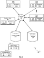
FIG. 1 is a block diagram illustrating a distributed storage system, according to one embodiment. -
FIGs. 2A-2D are flowcharts illustrating method(s) for operation of a node in interval-controlled replication, according to one or more embodiments. -
FIG. 3 is a flowchart illustrating a method for operation of a coordinator node in interval-controlled replication, according to one embodiment. -
FIGs. 4-7 are diagrams illustrating access by nodes of a distributed storage system, during interval-controlled replication, according to one embodiment. -
FIGs. 8-10 are diagrams illustrating communication between various nodes and storage devices during interval-controlled replication, according to one embodiment. -
FIG. 11 is a flowchart illustrating a method for operation of a coordinator node in interval-controlled replication, according to one embodiment. -
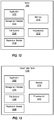
FIG. 12 is a block diagram illustrating various components of a node, according to one embodiment. -
FIG. 13 is a block diagram illustrating various components of a coordinator node, according to one embodiment. -
FIG. 14 is a block diagram illustrating a network architecture in which embodiments of the present application can be implemented. -
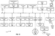
FIG. 15 is a block diagram that illustrates an example of a computer system suitable for implementing embodiments of the present application. - While the embodiments of the application are susceptible to various modifications and alternative forms, specific embodiments are provided as examples in the drawings and detailed description.
- Although the present invention has been described in connection with several embodiments, the invention is not intended to be limited to the specific forms set forth herein. On the contrary, it is intended to cover such alternatives, modifications, and equivalents as can be reasonably included within the scope of the invention as defined by the appended claims.
- Modern distributed storage environments may include multiple storage objects connected via one or more interconnection networks. The interconnection networks provide the infrastructure to connect the various elements of a distributed shared storage environment. Storage systems frequently use data redundancy mechanisms to ensure data integrity, consistency, and availability. Other uses for data redundancy may include backing up data, distributed load sharing, disaster recovery, or point-in-time analysis and reporting. One approach to data redundancy is to copy or replicate data from a primary storage system to a second or replicated storage system. In other words, a storage system may duplicate data written to the primary copy of a data block to redundant or replicated copies of that data block in other, secondary storage systems. In some designs this copying is done synchronously when the data I/O is preformed. In other designs this replication may be performed asynchronously with the second storage system's data state lagging the primary storage state by a time interval that can be anywhere from fractions of a second to many hours, depending on the design objectives and technologies used. Periodic replication can also be used, where writes to the second storage system are accumulated and written in batches, e.g., at every period.
-
Figure 1 is a block diagram illustrating adistributed system 100 that includes a collection of nodes and storage. Distributedsystem 100, e.g., a cluster, includes several nodes, e.g., nodes 102(1), 102(2) - 102(n) and acoordinator node 104. Each node can communicate with primary storage, e.g.,storage 112, using a network, e.g.,network 116. Furthermore, each node can communicate with a secondary storage, e.g.,storage 114, using a network, e.g.,network 116.Network 116 can include a local area network (LAN), a wide area network (WAN), a storage area network (SAN), Ethernet, and/or any combination thereof. It is noted thatdistributed system 100 may include a different number of nodes. - Each node 102(1)-102(n) can include one or more of applications 106(1)-106(n) and one or more of management modules 108(1)-108(n). Similarly,
coordinator node 104 can include application 106(3) andmanagement module 110. Each such application 106(1)-106(n) can originate reads and writes to and from storage. For example, application 106(1) can originate a write toprimary storage 112. Node 102(1) can then perform this write toprimary storage 112. This write can also be replicated tosecondary storage 114, such as by using a management module 106(1). Management module 106(1) can perform replication and other service(s) for node 102(1), as well as for other node(s) indistributed system 100. In one embodiment, it is assumed that when each application issues a write to certain data, that application does not write to this data (or to dependent data) until the first-in-time write is completed. In one embodiment, a management module associated with an application acknowledges to that application that such first-in-time write is complete. Upon receiving this acknowledgement from its associated management module, the application can then issue the dependent write. In one embodiment, a management module can be associated with application on that resides on the same node, e.g., management module 108(1) is associated with application 108(1) on node 102(1). However, in other embodiments, other associations between management modules and applications are contemplated. - Interval-controlled replication, as described herein, may be implemented on distributed or clustered computing environments, such as the one illustrated in
Figure 1 . As shown inFigure 1 , a set of source nodes, such as nodes 102(1)-102(n) may write data to one or more primary storage devices, such asprimary storage 112 and may also replicate the data writes to a replication target, such assecondary storage 114. The system illustrated inFigure 1 may implement interval-controlled replication, as described herein. Interval-controlled replication, in some embodiments, involves a node, such ascoordinator node 104, sending interval indications to other nodes indistributed system 100. These other nodes, e.g., nodes 102(1)-102(n) perform write(s) toprimary storage 112 andsecondary storage 114 in the manner described herein. Each data write from a node, such as from node 102(1), may include an identifier of a current interval. The interval-controlled replication can be used with at least three replication modes, i.e., synchronous replication, asynchronous replication, and periodic replication, as described herein. - Synchronous replication typically ensures that a remote copy of the data is created at the time the primary copy is updated. The remote copy can be created to be substantially similar to the primary copy. In synchronous replication, an I/O operation is not considered done until completion is confirmed at both
primary storage 112 and secondary storage 114 (e.g., mirrored site(s)). In one embodiment, an incomplete operation can be retried and/or rolled back at both locations by the application and/or the management module, so as to ensure that the remote copy is (substantially) a mirror image of the primary. During replication, a remote copy of the data is created at the time the primary copy is updated. - For example, if node 102(1) writes to a first data object using both
primary storage 112 andsecondary storage 114, then use of interval-controlled replication ensures that writes that start in an interval do not complete in the same interval. In addition, node 102(1) or node 102(2) do not issue any writes to either this first data object, or to a second data object that is dependent on the first write, until node 102(1) completes its (first) writes to both objectprimary storage 112 andsecondary storage 114. This ensures that, when using interval-controlled replication, no dependent I/O is written by the same or another node within the same interval as the original I/O write. Interval-controlled replication applies to nodes writing data to bothprimary storage 112 and tosecondary storage 114. A node implementing interval-controlled replication that received I/O in interval m will not complete this I/O until nodes (e.g., all nodes of a certain subset) have moved to the interval (m+1). In some embodiments, a node has "moved" to the next interval when it acknowledges this next interval. Various implementations of such acknowledgements are described in the following figures. Depending on the implementation, it is assumed that node(s) moved to the interval (m+1) when the node(s) started the interval (m+2). In another implementation, it is assumed that a node has moved to the interval (m+1) when this node has send back messages acknowledging the interval (m+1). In other words, for a given node, I/Os on any node that were received in interval m are independent of each other because no other node can complete any of these I/Os until interval m+1. - In one embodiment, for synchronous replication, a node waits for an acknowledgement from the primary storage, an acknowledgement from the secondary storage, and an interval indication for a next interval before issuing the next I/O write that is dependent on the previous I/O write. For example, management module 108(1) for node 102(1) waits on an acknowledgement from
primary storage 112 regarding a first local write (e.g., having an associated ID for interval m), an acknowledgement from the secondary storage regarding a first remote write (e.g., having an associated ID for interval m), an interval indication for a next interval (e.g., m+1) as well as acknowledgement(s) that the other nodes in distributedsystem 100 have moved to this next interval (m+1) before acknowledging to application 106(1) that the first I/O write (i.e.., the first local write and the first remote write) is complete. Once application 106(1) receives such acknowledgement from its associated management module 108(1), application 106(1) can issue the next I/O write that is dependent on the first I/O write. - In one embodiment, for asynchronous replication, a node waits for an acknowledgement from the primary storage and an interval indication for a next interval before issuing the next I/O write that is dependent on the previous I/O write. In other words, in contrast with the synchronous replication, the node in asynchronous replication does not wait for an acknowledgement from the secondary storage before sending an acknowledgement to the application. For example, management module 108(1) for node 102(1) waits on an acknowledgement from
primary storage 112 regarding a first local write (e.g., having an associated ID for interval m) and an interval indication for a next interval (e.g., m+1) as well as acknowledgement(s) that the other nodes in distributedsystem 100 have moved to this next interval (m+1) before acknowledging to application 106(1) that the first I/O write (i.e.., the first local write) is complete. Once application 106(1) receives such acknowledgement from its associated management module 108(1), application 106(1) can issue the next I/O write that is dependent on the first I/O write. However, at some point, the secondary storage acknowledges the remote write(s).Secondary storage 114 will apply all I/O writes for interval (m) before it applies any I/O writes for next interval (m+1). - In one embodiment, for periodic replication, a node copies data from primary storage to secondary storage at certain periods. For example, data to be replicated can be collected by a node, such as by using a snapshot and/or using another technique. In one embodiment, the node can use a local storage, such as a log and/or a staging area, where remote writes can be accumulated. At the certain time periods, this accumulated data can be written to the secondary storage, such as by using multiple remote writes (e.g., batch writes). The node in periodic replication does not wait for an acknowledgement from the secondary storage before sending an acknowledgement to the application. For example, management module 108(1) for node 102(1) waits on an acknowledgement from
primary storage 112 regarding a first local write (e.g., having an associated ID for interval m) and an interval indication for a next interval (e.g., m+1) as well as acknowledgement(s) that the other nodes in distributedsystem 100 have moved to this next interval (m+1) before acknowledging to application 106(1) that the first I/O write (i.e.., the first local write) is complete. Once application 106(1) receives such acknowledgement from its associated management module 108(1), application 106(1) can issue the next I/O write that is dependent on the first I/O write. As noted, each such I/O write is accumulated, and then written to the secondary at certain periods. - For all three replication types, in one embodiment, each such interval indication can be implemented as
interval indication 118 ofFigure 1 .Interval indication 118 can includeinterval ID 120 anddata 122, although other implementation(s) are contemplated. Each node can then determine the current interval from theinterval ID 120 of each receivedinterval indication 118. For example, a node, such as a coordinator node, sends interval indications, such as starting with interval m. Each node that receives an interval indication performs 170 operations for that interval. The coordinator node can send these intervals on a certain schedule, i.e., at certain intervals.Data 122 ofinterval indication 118 can also include other information, such as a list of other nodes that responded with acknowledgements to previous interval indications. - The length of these intervals can be dynamically determined for each distributed storage system. In many cases, the remote I/O write latency is the limiting factor, i.e., the elapsed time between a node write to a remote storage and acknowledgement of that write from this remote storage. In one implementation,
coordinator node 104 can determine, e.g., by using management module 110(1) the interval length, such as based on historical data and/or analysis. For example, if local I/Os for nodes 110(1)-110(n) take under 1 ms to complete, and remote I/Os for these nodes take, on the average, from 3ms to 10 ms to complete, then an interval can be set to 5 ms. In this example, for an I/O (e.g., a remote write by node 102(1)) that takes 7 ms, if this I/O write starts in interval m, then it completes in an interval (m+1). When node 102(1) initiates this remote I/O write, nodes 102(1)-102(n) are in interval m. No other node writes to the same data during this interval m. Next, nodes then receive interval indications for interval (m+1). Another node, e.g., node 102(n), will not attempt to write to the same, or dependent, data, until node 102(1) is finished with the remote I/O. - In one embodiment,
coordinator node 104 sends interval notifications to node(s) 102(1)-102(n). In response to receiving one of these interval notifications, each node 102(1)-102(n) can also complete I/O operation(s) started in the previous interval. In one embodiment, the interval notifications can indicate start of intervals. In another embodiment, the interval notifications can indicate other time points, such as end of intervals, half-way points of intervals, etc. For example,interval indications 118 can include associated interval numbers inID 120. The interval numbers can be associated with the interval notifications, such as an interval notification at time 0 can have an interval number of 1, the next interval notification can have an interval number of 2, etc. However, in other implementations, the interval indications can use different method(s) of indicating progression from one interval indication to the next one. - In one embodiment, node 102(1) receives a first interval indication, e.g., from
coordinator node 104. The first interval indication indicates a start of a first interval. Upon receiving the first interval indication, node 102(1) can initiate local writes toprimary storage 112. At this time, node 102(1) can also initiate remote writes tosecondary storage 114. In one embodiment, the remote writes can be performed as part of a replication process, e.g., of replicating some or all of the data written to primary storage. Both the remote write and the local write can include an associated time stamp. This time stamp can indicate the interval number of the interval notification (i.e., indicate the first interval notification). It is noted that each node issues multiple writes during each interval, and these writes are associated with the current interval. However, the replication mode controls how application(s) for node(s) issue dependent write(s). - In one embodiment, node 102(1) can acknowledge that I/O writes from the first interval are completed when nodes 102(1)-102(n) receive and acknowledge the next interval notification (e.g., a second interval notification) assuming that both the local writes and the remote writes have completed. In one embodiment, frequency of such interval can be determined (e.g., by coordinator node 104) such that in most cases the second interval indication is sent to (and also received and acknowledged by) node(s) 102(1)-102(n) before
remote storage 114 acknowledges that the remote writes send in the previous interval are finished. This ensures that application I/O completion is not delayed pending next interval indication; in other words, application I/O latency is unchanged even with introduction of interval control. In one embodiment,remote storage 114 can acknowledge that a remote write has completed to any of node(s) 102(1)-102(n) and/orcoordinator node 104. In one embodiment, after receiving the second interval indication, any of nodes 102(1)-102(n) will continue to issue additional I/O writes tolocal storage 112 andremote storage 114. Similarly as described above, nodes 102(1)-102(n) do not acknowledge (e.g., to applications 106(1)-106(n), respectively) that these additional I/O writes are finished until nodes 102(1)-102(n) receive and process a third interval indication and when both these additional local and remote writes have completed. - In one embodiment,
coordinator node 104 receives acknowledgement(s) from node(s) 102(1)-102(n). These acknowledgements are sent by node(s) 102(1)-102(n) to acknowledge receipt of interval indication(s). In one embodiment, each such acknowledgement can be implemented asacknowledgement 124 ofFigure 1 .Acknowledgement 124 can includeinterval ID 126 anddata 128, although other implementation(s) are contemplated. For example, each node 102(1)-102(n) can send an acknowledgement (e.g.,ID 126 of thatacknowledgement 124 indicating a first interval) tocoordinator node 104 acknowledging receipt of the first interval indication.Coordinator node 104 can then send the next interval indication (e.g.,ID 120 of thatinterval indication 118 indicating a second interval) in response to receiving acknowledgement(s) from nodes 102(1)-102(n), where these acknowledgement(s) indicate receipt of the interval indication indicating the first interval by nodes 102(1)-102(n). - In one embodiment, if one of nodes 102(1)-102(n) does not send such an acknowledgement back,
coordinator node 104 can delay sending the next interval indication for a certain time, after whichcoordinator node 104 would restart sending the next interval indications to nodes 102(1)-102(n) while keeping track of the interval(s) missed by such a delinquent node. Data sent in the next interval can include a list of active and any delinquent node(s). This data may be recorded in the primary and secondary storage. Once the delinquent node starts to responds to interval indications, the delinquent node can process any accumulated and/or in progress writes. In one implementation, such accumulated writes can be all processed using the interval indicating the time when the delinquent node restarted to respond to interval indications. - While interval-controlled replication is described herein mainly in reference to write requests from applications, file systems, volume managers and similar processes to storage devices, in general, interval-controlled replication may be utilized to provide consistent points or snapshots for any type of data stream. For example, interval-controlled replication may provide consistency checkpoints or snapshots across collections of logs, across collections of storage objects, or across sets of message streams in the distributed or clustered environment. Furthermore, the terms "I/O," "access," and/or "write" are used interchangeably herein to refer to data written by a source node to a replication target, such as during interval-controlled replication. The term "application" is used to refer to any processes executing on source nodes and replicating data to a replication target. Thus, "application," as used herein, may refer to a volume manager, file system, database application, storage replicator, or an end-user application, as well as any other processes replicating data.
-
Figure 2A is a flowchart illustrating amethod 200 for interval-controlled replication, according to one embodiment. As will be appreciated in light of the present disclosure, this method may be modified by in order to derive alternative embodiments. Also, the steps in this embodiment are shown in sequential order. However, certain steps may occur in a different order than shown, certain steps may be performed concurrently, certain steps may be combined with other steps, and certain steps may be absent in another embodiment.Method 200 is described with reference to variations of the elements described in connection withFigure 1 .Figure 2A illustrates operation of a node, such as node 102(1)-102(N) when operating in the synchronous or asynchronous replication mode. Differences in operation between these two modes are explained, as applicable. - In
element 202, a node starts a local and remote I/O write during a first interval. For example, node 102(1) can receive an indication of a first interval (such as from coordinator node 104). Once node 102(1) receives this indication, node 102(1) starts both a local write toprimary storage 112, as well as a remote write tosecondary storage 114. The remote write can be performed as part of replication, and can be started by node 102(1)'s management module. The local and remote write can be initiated by management module 108(1) as a part of application 106(1) performing an I/O write. - In
element 204, when operating in the synchronous replication mode, the node waits for the next interval, an acknowledgement of the remote write from the secondary storage, and an acknowledgement of the local write from the local storage. For example, node 102(1) waits for the acknowledgements fromprimary storage 112 andsecondary storage 114 of the local and remote writes (initiated in element 202), as well as for the next interval indication. In one implementation, node 102(1) can also wait on acknowledgements that other nodes 102(n)-102(n) in distributedsystem 100 have moved to this next interval. - In
element 204, when operating in the asynchronous replication mode, the node waits for the next interval and an acknowledgement of the local write from the local storage. For example, node 102(1) waits for the acknowledgements fromprimary storage 112 of the local write (initiated in element 202), as well as for the next interval indication. In one implementation, node 102(1) can also wait on acknowledgements that other nodes 102(n)-102(n) in distributedsystem 100 have moved to this next interval. However, when operating in the asynchronous mode, the node does not wait for an acknowledgement of the remote write from the secondary storage. - In
element 206, the node acknowledges to the application that the I/O write is complete. For example, management module 108(1) of node 102(1) sends an acknowledgement to application 106(1) that the I/O write initiated inelement 202 is completed. Once application 106(1) receives this acknowledgement, application 106(1) can issue an I/O write that is dependent on the I/O write ofelement 202. -
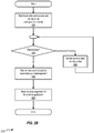
Figure 2B is a flowchart illustrating amethod 225 for the periodic replication mode using interval-controlled replication, according to one embodiment. As will be appreciated in light of the present disclosure, this method may be modified by in order to derive alternative embodiments. Also, the steps in this embodiment are shown in sequential order. However, certain steps may occur in a different order than shown, certain steps may be performed concurrently, certain steps may be combined with other steps, and certain steps may be absent in another embodiment.Method 225 is described with reference to variations of the elements described in connection withFigure 1 .Figure 2A illustrates operation of a node, such as node 102(1)-102(N) when operating in the periodic replication mode. - In element 226, a node starts a local write and accumulates a remote I/O write during a first interval. For example, node 102(1) can receive an indication of a first interval (such as from coordinator node 104). Once node 102(1) receives this indication, node 102(1) starts both a local write to
primary storage 112, as well as accumulates a remote write tosecondary storage 114. The remote write can be performed as part of replication, and can be started by node 102(1)'s management module. The local and remote write can be initiated by management module 108(1) as a part of application 106(1) performing an I/O write. Thus, in one embodiment, the node can perform front end logging, where the remote I/O write is collected to a log when the local I/O write is performed. In another embodiment, the node can perform back end logging, where the data is read from the primary storage and then written to a log. - In
element 228, the node determines whether the most recent period has ended. In other words, the node determines whether the period in which the most recent remote write (element 226) was initiated has completed. In one embodiment, each node can keep track of its own period(s). In another embodiment, the coordinator node can keep track of periods for the distributed storage system. The coordinator node can, as part of the interval indication (e.g., part of the data field), also send an indication of each period and/or period completions, to the nodes. For example, the interval can be set to 5 ms, and the period can be set to 15 seconds, so each period can include about 3,000 intervals. - In
element 230, the node waits for the next interval and an acknowledgement of the local write from the local storage. For example, node 102(1) waits for the acknowledgements fromprimary storage 112 of the local write (initiated in element 226), as well as for the next interval indication. In one implementation, node 102(1) can also wait on acknowledgements that other nodes 102(n)-102(n) in distributedsystem 100 have moved to this next interval. However, when operating in the periodic mode, the node does not wait for an acknowledgement of the remote write from the secondary storage. - In element 232, the node initiates accumulated remote I/O writes. For example, management module 108(1) of node 102(1) initiates the accumulated remote I/O writes (e.g., accumulated in the latest period). In one embodiment, the node takes a snapshot of at least a portion of the primary storage to generate the accumulated remote I/O writes. In one embodiment, the I/O writes can be accumulated from the log instead of using the snapshot of application data. The accumulated I/O writes are then written to the secondary storage. In one embodiment, if any I/O writes for interval (m) are included in the period, then all I/O writes for the previous interval (m-1) are also included. After element 232, the node performs
element 228. - It is noted that when operating in both the periodic and asynchronous replication modes, the secondary storage still acknowledges remote writes. However, in both cases, node's management module does not wait for these remote write acknowledgements before acknowledging to its associated application that the I/O write is completed. Since the remote I/O writes have associated interval information (e.g., indicating the interval in which that an application write for this remote I/O write was initiated), the secondary storage can apply these remote I/O writes in proper order, i.e., remote writes with an interval of (m) are processed before remote writes with interval of (m+1) are processed. In one embodiment, the secondary storage can queue and process remote I/O writes according to the interval of these writes. By processing the remote writes according to the interval, the secondary storage is consistent, i.e., does not create write conflicts for dependent data.
- In one embodiment, the secondary storage can send an acknowledgement when the remote write(s) are received but not yet completed, such as when the remote writes are queued at the secondary storage. In one embodiment, the secondary storage sends an acknowledgement when the remote write is actually written to storage. The secondary storage can also send separate acknowledgements for storing, but not completed, and another acknowledgement when the secondary write is completed.
- In
element 234, the node acknowledges to the application that the I/O write is complete. For example, management module 108(1) of node 102(1) sends an acknowledgement to application 106(1) that the I/O write initiated inelement 202 is completed. Once application 106(1) receives this acknowledgement, application 106(1) can issue an I/O write that is dependent on the I/O write ofelement 202. -
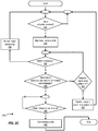
Figure 2C is another flowchart illustrating amethod 250 for interval-controlled replication, according to one embodiment. As will be appreciated in light of the present disclosure, this method may be modified by in order to derive alternative embodiments. Also, the steps in this embodiment are shown in sequential order. However, certain steps may occur in a different order than shown, certain steps may be performed concurrently, certain steps may be combined with other steps, and certain steps may be absent in another embodiment.Method 250 is described with reference to variations of the elements described in connection withFigure 1 .Method 250 is a variation ofmethod 200 described above with reference toFigure 2A .Figure 2C illustrates operation of a node, such as node 102(1)-102(N) when operating in the synchronous or asynchronous replication mode. Differences in operation between these two modes are explained, as applicable. - In
element 252, it is determined whether an interval indication is received. For example, node 102(1) determines whether an interval indication is received fromcoordinator node 104. The received interval indication can include an interval ID and data. The interval ID can indicate the current interval. For example, node 102(1) receives an interval indication for interval m. - In
element 254, the node can associate I/O writes with the current interval. For example, once node 102(1) receives the interval indication, node 102(1) can associate both local and remote I/O writes with the interval ID of the interval indication. As noted above, remote writes can be performed as part of replication, and can be started by node 102(1)'s management module. The local and remote writes can be initiated by management module 108(1) as a part of application 106(1) performing an I/O write. These two writes can be performed substantially at the same time, as desired. - In
element 256, a determination is made whether batch processing can be performed. For example, node 102(1) can be replicating large volumes of data (e.g., fromprimary storage 112 to remote storage 114). A portion of such replication can be latency sensitive, e.g., when replicating a transaction log. In this case, for select devices, a node may not wait for interval to complete before sending back completion acknowledgements (e.g., to coordinator node 104). - Element 258 is performed if it is determined (i.e., in element 256) that batch processing is performed. In one implementation, node 102(1) can perform numerous I/O writes without having received acknowledgements for all of the outstanding writes. For example, if there are 100 data elements to be replicated, these 100 data elements can be written using the same interval ID (e.g., 100). In one embodiment, all such I/O being batched is processed before any other I/O writes in the secondary storage, since these may be dependent I/O in the same interval(s). Management module(s) can also check whether any I/O being issued by a node does not overlap with the I/O being batched.
- In
element 260, when operating in the synchronous replication mode, if it is determined that node 102(1) is not performing batch processing, the node waits for the next interval and acknowledgement of the remote write from the secondary storage. The node can also wait for an acknowledgement of the local write from the local storage. In one embodiment,element 260 is similar toelement 204 ofmethod 200. For example, node 102(1) receives an interval indication for interval (m+1). It is noted that node 102(1) can receive the next interval indication and receive the acknowledgements fromlocal storage 112 and fromremote storage 114 in any order. - In
element 260, when operating in the asynchronous replication mode, if it is determined that node 102(1) is not performing batch processing, the node waits for the next interval and for an acknowledgement of the local write from the local storage. In one embodiment,element 260 is similar toelement 204 ofmethod 200. For example, node 102(1) receives an interval indication for interval (m+1). It is noted that node 102(1) can receive the next interval indication and receive the acknowledgements fromlocal storage 112 in any order. However, when operating in the asynchronous mode, the node does not wait for an acknowledgement of the remote write from the secondary storage. - In
element 262, node 102(1) determines whether there is a network and/or coordinator node error. For example, node 102(1) can determine such network and/or coordinator node error if a certain time period has elapsed since the previous interval indication was received by node 102(1). Inelement 264, node 102(1) can initiate handling of such a network / coordinator node error. For example, node 102(1) can initiate a process where another node (e.g., node 102(2)) becomes the coordinator node for distributedstorage system 100. Once the network / coordinator node error is handled,method 250 returns toelement 256. - In
element 266, node 102(1) determines whether other node(s) in the distributed network are in the next interval. In one embodiment, node 102(1) determines that the other node(s) in the network have moved to the next interval (i.e., (m+1)) if node 102(1) receives an interval indication for interval (m+2). In another embodiment, node 102(1) determines that the other node(s) in the network have moved to the next interval (i.e., interval (m+1)) if node 102(1) receives an interval acknowledgment indication from coordinator node indicating that the other node(s) in the network have moved to the next interval (i.e., interval (m+1)). In yet another embodiment, node 102(1) determines that the other node(s) in the network have moved to the next interval (i.e., interval (m+1)) if node 102(1) receives the next sub-interval indication(s). - In
element 268, the node acknowledges to the application that the I/O write is complete. For example, management module 108(1) of node 102(1) sends an acknowledgement to application 106(1) that the I/O write initiated inelement 254 is completed. Once application 106(1) receives this acknowledgement, application 106(1) can issue an I/O write that can be dependent on the I/O write ofelement 254. In other words, for synchronous replication, node 102(1) does not acknowledge that the I/O write (started in element 254) is finished until the conditions ofelement 260 are met and the other node(s) are in the next interval. -
Figure 2D is another flowchart illustrating amethod 275 for interval-controlled replication, according to one embodiment. As will be appreciated in light of the present disclosure, this method may be modified by in order to derive alternative embodiments. Also, the steps in this embodiment are shown in sequential order. However, certain steps may occur in a different order than shown, certain steps may be performed concurrently, certain steps may be combined with other steps, and certain steps may be absent in another embodiment.Method 275 is described with reference to variations of the elements described in connection withFigure 1 .Method 275 can be executed by each node in the distributed storage system to select the type of replication. - In
element 276, according to one embodiment, a node can receive a selection of replication type. For example, one or more of node(s) or coordinator node can receive this selection. This selection can be received prior to starting the replication process, or it can be received during replication process. In one embodiment, management modules (including the coordinator node) for all nodes in the distributed system use the same replication mode. Therefore, any replication mode changes are agreed upon between nodes. For example, the coordinator node can send replication mode notifications to the management modules of the other nodes. In one embodiment, the coordinator node can wait on replication mode acknowledgment messages from the other nodes before switching to another replication mode. In one embodiment,element 276 is performed prior to starting replication. In another embodiment,element 276 is performed during replication, such that the replication mode can be changed (e.g., by a user input and/or input from another node / module) dynamically. - In
element 278, a determination is made whether the selection indicates synchronous replication. If the selection indicates synchronous replication, then the node operates in synchronous mode (element 280). If the selection does not indicate synchronous replication, then, in element 282, a determination is made whether the selection indicates asynchronous replication. If the selection indicates asynchronous replication, then the node operates in asynchronous mode (element 290). If the selection does not indicate asynchronous replication, then the node operates in periodic mode (element 284). - When operating in the synchronous mode (element 280), the node (and/or the coordinator node) can calculate (element 286) metrics for this node. In element 288, based on these metrics, a determination is made whether to switch to asynchronous replication. In one embodiment, these metrics include whether or not the secondary storage can send acknowledgements of remote writes within a predetermined time period. In one embodiment, these metrics include network statistics, responsiveness of node(s), and/or responsiveness of the secondary storage of the distributed storage system. If the determination indicates that a switch to the asynchronous replication should be made, this node can switch its operation to asynchronous replication (element 290). For example, if the latency of the secondary storage is too large, then the distributed storage system would operate more efficiently in the asynchronous replication mode instead of the synchronous replication mode.
- When operating in the asynchronous mode (element 290), the node (and/or the coordinator node) can calculate (element 292) metrics for this node. In
element 294, based on these metrics, and the original synchronization mode (element 276), a determination is made whether to switch to synchronous replication. In one embodiment, these metrics include whether or not the secondary storage can send acknowledgements of remote writes within a predetermined time period. In one embodiment, these metrics include network statistics, responsiveness of node(s), and/or responsiveness of the secondary storage of the distributed storage system. For example, a metric can indicate that a sufficient number (e.g., all) of outstanding remote writes can be written to the secondary storage; the threshold for the sufficient number of outstanding remote I/O writes being written can be determined dynamically. If the determination indicates that a switch to the synchronous replication should be made, this node can switch its operation to synchronous replication (element 280). For example, the mode can be switched to synchronous if the determination using the metrics indicates that this would be more efficient, and if the original selection was for synchronous mode. -
Figure 3 is a flowchart illustrating a method for operation of a coordinator node in interval-controlled replication, according to one embodiment. As will be appreciated in light of the present disclosure, this method may be modified by in order to derive alternative embodiments. Also, the steps in this embodiment are shown in sequential order. However, certain steps may occur in a different order than shown, certain steps may be performed concurrently, certain steps may be combined with other steps, and certain steps may be absent in another embodiment.Method 300 is described with reference to variations of the elements described in connection withFigure 1 .Figure 3 illustrates the operation of the coordinator node in synchronous, asynchronous, or periodic replication. In one embodiment, the coordinator node operates substantially similar in these three replication modes, unless noted otherwise. Furthermore, in one embodiment, the application associated with the coordinator module (e.g., application 106(3)) also can issue I/O writes that are replicated using one of the three replication modes described herein. In other words, the coordinator node can operate as one of the other nodes, in addition to operating as the coordinator node. In one embodiment, for a larger storage system that includes secondary site(s), the coordinator node can also send interval information to one or more nodes in the secondary site(s) and/or to peer coordinator node(s) in secondary site(s). - In
element 302, a coordinator node sends interval indications according to a time interval.Coordinator node 104 can use a management module 110(1) to keep track of time intervals. For example,coordinator node 104 can send interval indication(s) to nodes 102(1)-102(n) indicating time interval m during a first interval. Similarly, example,coordinator node 104 can send interval indication(s) to nodes 102(1)-102(n) indicating time interval (m+1) during a second interval. - In one embodiment, when the distributed storage system is operating in periodic replication mode, the coordinator node can, as part of the interval indication (e.g., part of the data field), or in a separate message, also send an indication of each period and/or period completions, to the nodes. For example, the coordinator node can send period indicators indicating the current period. The coordinator node can also send period change indicators indicating that the next period has started.
- In element 304, the coordinator node determines whether the time interval should be adjusted. Such a determination can be made when the time interval is too large or too small. The determination of element 304 can be dynamic, i.e., management module 110(1) can determine, e.g., based on analysis of historical data, that a time interval is too short (or too long). For example, if a remote I/O is both started and completed (e.g., the remote I/O sends an acknowledgement back to the node that initiated this remote I/O) in the same interval, then the interval may be too long. Such analysis may be performed using statistics, and management module 110(1) may use a threshold to determine whether enough remote I/O writes start and complete in the same interval. For example, if only 1% of such remote I/O writes start and complete in the same interval, then management module 110(1) may determine that the interval does not need adjusting. On the other hand, if 90% of such remote I/O writes start and complete in the same interval, then management module 110(1) may determine that the interval does need adjusting.
- In element 306, the coordinator node adjusts the time interval. For example, if management module 110(1) determines that the time interval is too short, management module 110(1) adjusts the time interval to a longer interval, as determined. Similarly, if management module 110(1) determines that the time interval is too long, management module 110(1) adjusts the time interval to a shorter interval, as determined.
-
Figures 4-7 illustrate general timing diagrams of various embodiments of interval-controlled replication.Figures 4-7 are described with reference to variations of the elements described in connection withFigure 1 as well as methods of flowcharts depicted infigures 2A-2D and3 , among others.Node 1 can be implemented by node 102(1), andnode 2 can be implemented by node 102(2). For simplicity of illustration, it is assumed that both nodes can process message(s) from a coordinator node at substantially the same time, and thus start new interval at substantially the same time. However, there may be a small, but finite, delay and/or skew between the nodes receiving such message(s). -
Figure 4A is a general timing diagram 400 of I/O writes by two nodes of a distributed storage system that implements the interval-controlled replication, according to one embodiment. A coordinator node (e.g., coordinator node 104) can send interval indications tonodes interval 1 starts at 402(1) and ends at 402(2),interval 2 starts at 402(2) and ends at 402(3), etc.Figure 4A illustrates the operation of nodes in synchronous, asynchronous, or periodic replication. - In one embodiment, upon receiving
interval indication 1, bothnodes interval 1 has started.Node 1 can then start first I/O 404(1). While I/O 404(1) accesses data, no other node can perform I/O write(s) to the overlapping or dependent data. While only one I/O is shown per interval, both nodes could be performing hundreds of independent I/Os in each interval.Node 1 can complete I/O 404(1) oncenode 1 receives indication of the next interval, e.g., indicating thatinterval 2 404(2) has started.Node 2 can, upon receiving indication of this next interval, start an I/O write 406(1) that may be dependent on I/O write 404(1). - However,
node 1 completes I/O write 404(1) in the second interval.Node 2 does not complete its potentially data dependent I/O write 406(1) untilinterval 3, upon receiving interval indication forinterval 3. Similarly, potentially data dependent I/O write 404(2) bynode 1 is not started until the third interval, and it is not completed until the fourth interval. To take into account slight difference in times when node process interval message, I/O completions do not take place until all nodes have received next interval indication. This may require additional message between nodes and/or coordinator node. - In one embodiment, shown in
Figure 4B , receipt of an interval indication might be taken as an acknowledgement that previous interval is received by all nodes.Figure 4B is a general timing diagram 450 of I/O writes by two nodes of a distributed storage system that implements the interval-controlled replication, according to one embodiment. A coordinator node (e.g., coordinator node 104) can send interval indications tonodes Figure 4B illustrates the operation of nodes in synchronous, asynchronous, or periodic replication. - In the implementation illustrated by
Figure 4B , the management module fornode 1 will acknowledge that any I/O writes that started in interval 'm' will be completed in interval 'm+2.' since at that point all nodes have acknowledged receipt of interval 'm+1.' For example,node 1 can initiate I/O write 454(1) in interval 1 (i.e., interval m). This I/O write is not acknowledged (i.e., the management module ofnode 1 does not acknowledge this I/O write to the application that initiated this write) untilnode 1 receives interval indication for interval 3 (i.e., interval (m+2). In one embodiment, when a node received a new interval indication such as 'm+1,' this node will use this new interval indication for future I/O writes, even if other nodes have not yet received this new interval indication. -
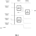
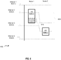
Figure 5 is a general timing diagram 500 of I/O writes by two nodes of a distributed storage system, according to one embodiment. A coordinator node (e.g., coordinator node 104) can send interval indications tonodes Figure 5 illustrates how a delay can create I/O write issues fornodes Figure 5 illustrates the operation of nodes in synchronous, asynchronous, or periodic replication. - In one embodiment, upon receiving
interval indication 1, bothnodes interval 1 has started.Node 1 can then start first I/O 504(1). While I/O 504(1) accesses data, no other node can perform an I/O write to the same data.Node 1 can complete I/O 404(1) oncenode 1 receives indication of the next interval, e.g., indicating thatinterval 2 404(2) has started. However, if there is a network or delay issue, thennode 2 does not receive an interval indication thatinterval 2 has started. As a result,node 2 can then start I/O 506(1) that is dependent onnode 1's I/O 504(1). This may be problematic, e.g., as I/O write 506(1) is dependent on I/O 504(1) and yet both are performed within the same interval. -
Figure 6 is a general timing diagram 600 of I/O writes by two nodes of a distributed storage system, according to one embodiment. A coordinator node (e.g., coordinator node 104) can send interval indications tonodes Figure 6 illustrates one embodiment of how interval-controlled replication can be used to overcome a possible issue with I/O writes (shown inFigure 5 ).Figure 6 illustrates the operation of nodes in synchronous, asynchronous, or periodic replication. - In one embodiment, upon receiving
interval indication 1, bothnodes interval 1 has started.Node 1 can then start first I/O 604(1). While I/O 604(1) accesses data, no other node can perform an I/O write to the same data.Node 1 can complete I/O 604(1) oncenode 1 receives indication of the next interval, e.g., indicating thatinterval 2 604(2) has started. However, if there is a network or delay issue, thennode 2 does not receive an interval indication thatinterval 2 has started.Delay 608 illustrates howlong node 2 receives an interval indication of second interval 602(2) afternode 1 receives such an indication. - In one embodiment, both
node 1 andnode 2 can send acknowledgements to the coordinator node indicating receipt of the most recent interval indication. For example, bothnode interval 1 602(1). Upon receipt of interval indication forinterval 2 602(2),node 1 can send interval acknowledgement indicating receipt of this interval indication. However,node 2 does not receive this second interval indication (e.g., due to network delay or other issues), until afterdelay 608. As a result,node 2 does not send an acknowledgement of receiving the second interval indication until afterdelay 608. In one embodiment, the coordinator node may send additional indicators to indicate when the remaining nodes, includingnode 2, acknowledge receipt of the second interval indication.Node 1 completes I/O 604(1) after receiving such an additional indication, with I/O 604(1) being delayed anextra amount 610. As a result, dependent I/O write 606(1) bynode 2 is not started in the same interval as I/O write 604(1). Furthermore, the coordinator node can then shift and adjust the time of the next interval indicators such that bothnodes interval 4 602(4). -
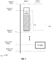
Figure 7 is a general timing diagram 700 of I/O writes by two nodes of a distributed storage system, according to one embodiment. A coordinator node (e.g., coordinator node 104) can send interval indications tonodes Figure 7 illustrates one embodiment of processing of I/O writes whennode 2 does not acknowledge interval indications. For example, if there is a network / delay issue, thennode 2 does not receive an interval indication thatinterval 2 has started.Node 2 can also be too busy to acknowledge receipt of the second interval indication. As a result, the coordinator node can delay with sending of the next interval indication fordelay 708.Figure 7 illustrates the operation of nodes in synchronous replication. - After
delay 708, the coordinator node can resume sending interval indications to nodes in the distributed system. In one embodiment, the coordinator node can send extra indication messages to nodes indicating which nodes have acknowledged receipt of the interval indication and/or which nodes (i.e., delinquent node(s) have not acknowledged receipt of the interval indication). In another embodiment, the coordinator node can send partial-interval indication messages to nodes indicating which nodes have acknowledged receipt of the interval indication and/or delinquent node(s).Node 1 can complete I/O write 704(1) after a delay 710, however, the interval may change. - In one embodiment, for synchronous replication, if the delinquent node(s) attempt to initiate writes to the secondary storage, at this point it is not possible to correctly identify/associate interval with any such in-progress I/O writes from the delinquent node(s). As a result, such I/O writes will not be included in the secondary storage until the delinquent node(s) resume acknowledging interval indications from coordinator node. During the time that the delinquent node (e.g., the second node) is not responding to interval indications, the second node could be sending I/O writes to the primary and/or secondary storage, and associating these I/O writes with the interval last known by the second node.
- In one embodiment, once the second node re-starts to respond to interval notifications (e.g., to a new interval(s)), the coordinator node can notify the second node about the missed interval range. The second node can then associate any outstanding and in-progress I/O writes as belonging to a new interval (e.g., interval 100) received from the coordinator node. In one embodiment, this can include associating I/O writes that were completed to primary and/or secondary storage writes as belonging to this new interval. In other words, the writes that were processed since the last acknowledged interval till now be treated as if they were received in last received interval. This is acceptable, since the second node could not have acknowledged the application without acknowledging new interval indication to the coordinator node. The second node can also resume I/O writes 706(1).
-
FIGs. 8-10 are diagrams illustrating communication between various nodes and storage devices during interval-controlled replication, according to one embodiment.Figures 8-10 are described with reference to variations of the elements described in connection withFigure 1 as well as methods of flowcharts depicted infigures 2A-2D and 3, among others. In some embodiments, nodes send messages to the coordinator node to acknowledge receipt of an interval indication. In one embodiment, when a node receives interval indication indicating interval (m+2), it is assumed that all nodes that were active (i.e., not delinquent) in interval (m+1) did acknowledge receiving the previous interval to the coordinator node. In one embodiment, the interval indication (e.g., data 122) can indicate whenever active membership changes (e.g., when some node(s) don't acknowledge an interval, or a node that was delinquent earlier, but is active now). In one embodiment, when the interval indication does not include information regarding other nodes, this can indicate that all active nodes acknowledged the previous interval.Figures 9-10 illustrate the operation of nodes in the synchronous replication mode, unless noted otherwise. It is noted thatFigures 8-10 illustrate operation of nodes in the same single replication mode (e.g., all nodes operating in the synchronous replication mode). -
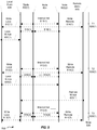
Figure 8 is a timing diagram 800 of communication between various elements of a distributed storage system that implements the interval-controlled replication, according to one embodiment. Element 802(1) illustrates a first node, e.g.,node 1 102(1), element 802(2) illustrates a second node, e.g.,node 2 102(2), element 804(1) illustrates a coordinator node, e.g.,node 104,element 806 illustrates a local storage, e.g.,primary storage 112, andelement 808 illustrates a remote storage, e.g.,secondary storage 114.Element 826 illustrates points in time at which various communications can be initiated.Figure 8 illustrates the operation of nodes in synchronous, asynchronous, or periodic replication. - At time T1 826(1),
coordinator node 804 sends interval indications 810(1) to first node 802(1) and second node 802(2) that indicate a first interval. In both synchronous and asynchronous replication modes, upon receiving interval indication 810(1), and during the first interval, first node 802(1) starts a first I/O write, i.e., both a first local write 812(1) (to local store 806) and a first remote write 814(1) toremote store 808. First remote write 814(1) can include an interval ID indicating the first interval. In periodic replication mode, first node 802(1) can accumulate the first remote write instead. In all three replication modes, and still during the first interval,local store 806 can send local write acknowledgement message(s) 816(1) (acknowledging completion of the first local write) to first node 802(1). First node 802(1) sends interval acknowledgement message 816(1) tocoordinator node 804 to acknowledge receipt of first interval indication 810(1). Similarly, second node 802(2) sends interval acknowledgement message 818(1) tocoordinator node 804 to acknowledge receipt of first interval indication 810(1). - At time T2 826(2),
coordinator node 804 sends interval indications 810(2) to first node 802(1) and second node 802(2) that indicate a second interval. In both synchronous and asynchronous replication modes, and upon receiving interval indication 810(2), and during the second interval, second node 802(2) starts both a second local write 812(2) (to local store 806) and a second remote write 814(2) toremote store 808. In periodic replication mode, second node 802(2) can accumulate the second remote write instead. In all three replication modes, and still during the second interval,local store 806 can send local write acknowledgement message(s) 820(2) (acknowledging completion of the second local write) to first node 802(1). In synchronous replication, during the second interval,remote store 808 can send remote write acknowledgement message(s) 822(1) (acknowledging completion of the first remote write) to first node 802(1). It is noted that in asynchronous replication,remote store 808 can also send remote write acknowledgement message(s) 822(1), however, management module of first node 802(1) does not wait on receiving this remote write acknowledgement message(s) 822(1) before acknowledging completion of the first write to its associated application. - It is noted that the second I/O write (i.e., second local write 812(2) and second remote write 814(2)) is not dependent on the first I/O write. Second remote write 814(2) can include an interval ID indicating the second interval. Both first and second nodes 802(1) and 802(2) send interval acknowledgement messages 816(2) and 818(2), respectively, to
coordinator node 804 to acknowledge receipt of second interval indication 810(2).Remote store 808 can send an acknowledgement once a batch of accumulated remote writes are written (i.e., at the end of a period). In periodic replication, writes are accumulated (in data volume and/or log) for a period and sent to the remote storage after the end of period (i.e., after data for previous periods have been sent). - At time T3 826(3),
coordinator node 804 sends interval indications 810(3) to first node 802(1) and second node 802(2) that indicate a third interval. When operating in synchronous replication, during the third interval, first node 802(1) can acknowledge that the first I/O write is complete, based on receiving acknowledgements from the local and remote store that the first local and remote I/O writes are completed, and that all nodes are in the second interval. When operating in asynchronous and periodic replication, during the third interval, first node 802(1) can acknowledge that the first I/O write is complete, based on receiving acknowledgements from the local store that the first local I/O write is completed, and that all nodes are in the second interval. For example, in all three replication modes, a management node of the first node can acknowledge to an application of the first node that the first I/O write is complete. This application can be requesting to issue the third I/O write. However, since the third I/O write is dependent on the first I/O write (i.e., there is data dependency in the data accessed by these writes), the application waits to issue the third I/O write until it receives the acknowledgement of the first I/O write being completed. Upon receiving interval indication 810(3), and during the third interval, first node 802(1) starts both a third local write 812(2) (to local store 806) and a third remote write 814(2) toremote store 808. Third remote write 814(3) can include an interval ID indicating the third interval. -
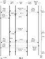
Figure 9 is a timing diagram 900 of communication between various elements of a distributed storage system that implements the interval-controlled replication, according to one embodiment. Element 902(1) illustrates a first node, e.g.,node 1 102(1), element 902(2) illustrates a second node, e.g.,node 2 102(2), element 904(1) illustrates a coordinator node, e.g.,node 104,element 906 illustrates a local storage, e.g.,primary storage 112, andelement 908 illustrates a remote storage, e.g.,secondary storage 114.Element 926 illustrates points in time at which various communications can be initiated.Figure 9 illustrates an embodiment of interval-controlled replication that uses extra indication messages. Nodes (e.g., nodes 902(1) and 902(2)) send messages tocoordinator node 904 to acknowledge receipt of an interval indication. In response,coordinator node 904 sends extra indication messages to nodes (e.g., nodes 902(1) and 902(2)) indicating which nodes have acknowledged receipt of the interval indication. - At time T1 926(1),
coordinator node 904 sends interval indications 910(1) to first node 902(1) and second node 902(2) that indicate a first interval. Upon receiving interval indication 910(1), and during the first interval, first node 902(1) starts a first I/O write, i.e., both a first local write 912(1) (to local store 906) and a first remote write 914(1) toremote store 908. First remote write 914(1) can include an interval ID indicating the first interval. First node 902(1) and second node 902(2) also send interval acknowledgements 916(1) and 917(1), respectively, tocoordinator node 904, that acknowledge receipt of interval indication 910(1). In response,coordinator node 904 sends interval acknowledgement indication messages 918(1) to nodes 902(1) and 902(2). Interval acknowledgement indication messages 918(1) can indicate which nodes have acknowledged receipt of the interval indication. Still during the first interval,local store 906 can send local write acknowledgement message 920(1), which acknowledges completion of the first local write, to first node 902(1). - At time T2 926(2),
coordinator node 904 sends interval indications 910(2) to first node 902(1) and second node 902(2) that indicate a second interval. First node 902(1) sends interval acknowledgement 916(2) to coordinator node that acknowledges first node's 902(1) receipt of second interval indication 910(2). However, second node 902(2) does not send interval acknowledgement tocoordinator node 904 that acknowledges second node's 902(2) receipt of second interval indication 910(2) until after adelay 930. As a result,coordinator node 904 waits (e.g., for at least the duration of delay 930) sending the interval acknowledgement indication messages 918(2) to nodes 902(1) and 902(2) until after second node 902(2) sends interval acknowledgement 917(2) tocoordinator node 904. In this example, since the second I/O write is dependent on the first I/O write (i.e., there is data dependency in the data accessed by these writes), second node 902(2) waits to initiate second local write 912(2) and second remote write 914(2) until receiving interval acknowledgement indication message 918(2) fromcoordinator node 904. Second remote write 914(2) can include an interval ID indicating the second interval. - It is noted that multiple I/O writes can occur between elements 916(2) and 917(2), but are not shown in
Figure 9 for simplicity. For example, after element 916(2), these I/O writes from first node 902(1) use second interval, but on second node 902(2) these I/O writes may use the first or second interval (depending upon whether second node has processed 910(2)). In one embodiment, after element 917(2), second node 902(2) will use second interval even before 918(2) is received. - Still during the second interval,
local store 906 can send local write acknowledgement message 920(2) to second node 902(2). During the second interval,remote store 908 can send remote write acknowledgement message 924(1) (acknowledging completion of the first remote write) to first node 902(1). At time T3 926(3),coordinator node 904 sends interval indications 910(3) tonodes -
Figure 10 is a timing diagram 1000 of communication between various elements of a distributed storage system that implements the interval-controlled replication, according to one embodiment. Element 1002(1) illustrates a first node, e.g.,node 1 102(1), element 1002(2) illustrates a second node, e.g.,node 2 102(2), element 1004(1) illustrates a coordinator node, e.g.,node 104,element 1006 illustrates a local storage, e.g.,primary storage 112, andelement 1008 illustrates a remote storage, e.g.,secondary storage 114.Element 1026 illustrates points in time at which various communications can be initiated. -
Figure 10 illustrates an embodiment of interval-controlled replication that uses sub-interval indication and acknowledgement messages. In this implementation, instead of sending two messages (interval indication and interval acknowledgement indication), the interval is split into two. At what would have been middle of an interval, a new partial-interval indication message can be sent that also is used as interval acknowledgement indication for the previous interval. With this approach, even though write completion waits for two intervals, effective elapsed duration is still the same as in the implementation ofFigure 9 . - Nodes (e.g., nodes 1002(1) and 1002(2)) send messages to
coordinator node 1004 to acknowledge receipt of an interval indication. In response,coordinator node 1004 sends the partial-interval indication messages to nodes at partial-interval times (e.g., midpoint of the original interval times) to indicate which nodes have acknowledged receipt of the previous interval indication. In one embodiment, nodes 1002(1) and 1002(2) acknowledge receipt of all interval indications. - At time T1 1026(1),
coordinator node 1004 sends interval indications 1010(1) to first node 1002(1) and second node 1002(2) that indicate a first interval. Upon receiving interval indication 1010(1), and during the first interval, first node 1002(1) starts both a first local write 1012(1) (to local store 1006) and a first remote write 1014(1) toremote store 1008. First node 1002(1) and second node 1002(2) also send interval acknowledgements 1016(1) and 1017(1), respectively, tocoordinator node 1004, that acknowledge receipt of interval indication 1010(1). Still during the first interval,local store 1006 can send local write acknowledgement message(s) 1020(1), that acknowledge completion of the first local write, to first node 1002(1). In response to receiving interval acknowledgements 1016(1) and 1017(1),coordinator node 1004 sends partial-interval acknowledgement indication messages 1010(2) to nodes 1002(1) and 1002(2) at time T1.5 1026(2), which may be substantially around 0.5 of the interval being used. Each partial-interval acknowledgement indication message also serves as interval acknowledgement indication message and can indicate which nodes have acknowledged receipt of the previous interval indication. In one embodiment, first node 1002(1) and second node 1002(2) also send interval acknowledgements 1016(2) and 1017(2), respectively, tocoordinator node 1004, that acknowledge receipt of interval indication 1010(2). - At time T2 1026(3),
coordinator node 1004 sends interval indications 1010(2) to first node 1002(1) and second node 1002(2) that indicate a second interval. First node 1002(1) sends interval acknowledgement 1016(3) tocoordinator node 1004 that acknowledges first node's 1002(1) receipt of second interval indication 1010(3). However, second node 1002(2) does not send interval acknowledgement tocoordinator node 1004 that acknowledges second node's 1002(2) receipt of second interval indication 1010(2) until after adelay 1030. As a result,coordinator node 1004 waits (e.g., for at least the duration of delay 1030) sending the next interval indication 1018(4) to nodes 1002(1) and 1002(2) until after second node 1002(2) sends interval acknowledgement 1017(4) tocoordinator node 1004. - In this example, since the second I/O write is dependent on the first I/O write (i.e., there is data dependency in the data accessed by these writes), second node 1002(2) waits to initiate second local write 1012(2) and second remote write 1014(2) until receiving the next interval indication 1018(4) from
coordinator node 1004. Second remote write 1014(2) can include an interval ID indicating the second interval. Still during the second interval,local store 1006 can send local write acknowledgement message 1020(2) to second node 1002(2). During the second interval,remote store 1008 can send remote write acknowledgement message 1024(1) (acknowledging completion of the first remote write) to first node 1002(1). At time T3 1026(5),coordinator node 1004 sends interval indications 1010(5) to first and second nodes 1002(1) and 1002(2). In one embodiment, partial intervals can be treated as regular intervals, and as such, an application write that started in the first interval will be acknowledged in the third interval (which ensures that all nodes have moved to second interval). Treating partial intervals as regular intervals can increase interval granularity, i.e., make the intervals smaller, without adding extra messages. -
Figure 11 is a flowchart illustrating a method for operation of a coordinator node in interval-controlled replication, according to one embodiment. As will be appreciated in light of the present disclosure, this method may be modified by in order to derive alternative embodiments. Also, the steps in this embodiment are shown in sequential order. However, certain steps may occur in a different order than shown, certain steps may be performed concurrently, certain steps may be combined with other steps, and certain steps may be absent in another embodiment.Method 1100 is described with reference to variations of the elements described in connection withFigure 1 .Method 1100 is a variation ofmethod 300 described above with reference toFigure 3 .Figure 11 illustrates the operation of the coordinator node in synchronous, asynchronous, or periodic replication. In one embodiment, the coordinator node operates substantially similar in these three replication modes, unless noted otherwise. - In
element 1102, a coordinator node sends interval indications according to a time interval.Coordinator node 104 can use a management module 110(1) to keep track of time intervals. For example, management module can send interval indication(s) to nodes 102(1)-102(n) indicating time interval m during a first interval. Similarly, example, management module can send interval indication(s) to nodes 102(1)-102(n) indicating time interval (m+1) during a second interval. - In
element 1104, the coordinator node determines whether acknowledgements (of receiving the previous interval indication) are received from substantially all nodes. In one embodiment, the coordinator node determines whether acknowledgements are received from all nodes in the distributed storage system. In another embodiment, the coordinator node determines whether acknowledgements are received only from an expected subset of nodes in the distributed storage system. The coordinator node can determine which nodes are expected to provide to answer with the acknowledgements. If acknowledgements are received from all of the expected nodes (i.e., either all nodes or the expected subset of nodes) in the distributed I/O system,method 1100 executeselement 1105. - In
element 1105, a time interval check is performed. In one embodiment,element 1105 includes elements 304 and 306 ofmethod 300. As such, if time interval adjustment is needed, then the time interval is adjusted. If time interval adjustment is not needed, then the time interval is not adjusted. In one embodiment, a delinquent node (i.e., a node that is expected to provide the acknowledgement but does not), responds with such an acknowledgement within the delay threshold specified inelement 1106, thenelement 1105 can shift and/or adjust the time interval accordingly (e.g., a situation described above with reference toFigure 6 ).Method 1100 then executeselement 1102. - In
element 1106, if coordinator node does not receive acknowledgements from the expected nodes, the coordinator node determines whether a delay in receiving these acknowledgements is longer than a threshold. In one embodiment, the value of this threshold can be determined prior to execution ofmethod 1100. In another embodiment, the value of this threshold can be dynamically determined, e.g., during execution ofmethod 1100. For example, the value of this threshold can be computed by the management module(s) analyzing speed of communication between nodes. If the delay is not longer than the threshold,method 1100 performselement 1108, such as where the coordinator module waits for a certain amount of time before executingelement 1104 again. Next,method 1100 proceeds toelement 1114, where the coordinator node sends the next interval indication using the next time interval. - In one embodiment, in
element 1102 and/or 1114, when the distributed storage system is operating in periodic replication mode, the coordinator node can, as part of the interval indication (e.g., part of the data field), or in a separate message, also send an indication of each period and/or period completions, to the nodes. For example, the coordinator node can send period indicators indicating the current period. The coordinator node can also send period change indicators indicating that the next period has started. - In
element 1116, the coordinator node determines whether acknowledgements (of receiving the previous interval indication of element 1114) are received from substantially all nodes, including the delinquent node(s). In one embodiment, the coordinator node determines whether acknowledgements are received from all nodes in the distributed storage system. In another embodiment, the coordinator node determines whether acknowledgements are received only from an expected subset of nodes in the distributed storage system. The coordinator node can determine which nodes are expected to provide to answer with the acknowledgements. If acknowledgements are received from all of the expected nodes (i.e., either all nodes or the expected subset of nodes, and including the delinquent node(s)) in the distributed I/O system,method 1100 executeselement 1102. If acknowledgements are not received from all of the expected nodes in the distributed I/O system,method 1100 executeselement 1114 again. The coordinator node can also communicate with the other nodes with information indicating that the delinquent node(s) can process I/O writes. In one embodiment, since any delinquent node(s) might not have received earlier messages, the coordinator node keeps sending new messages to the delinquent node(s) that indicate that these the delinquent node(s) need special processing. - In one embodiment, once the delinquent node starts to receive the interval indications from the coordinator, the delinquent node will take corrective action before acknowledging these interval indications. If this corrective action process is long, it may be few more intervals before the delinquent node is able to acknowledge the interval indications. Once the delinquent node acknowledges the interval indications, this node can be considered to be a node with good standing. In another embodiment, the delinquent node can acknowledge to the coordinator node that it in the corrective action process, and do the corrective action processing in background. In one embodiment, as described above with reference to
Figure 7 , this corrective action process includes the delinquent node can associating any outstanding and in-progress I/O writes as belonging to a new interval received from the coordinator node. -
Figure 12 is a block diagram of anode 1200, such as node 102(1)-102(n) described inFigure 1 .Node 1200 includes anapplication 1202, amanagement module 1204, afile system 1206,memory 1210, and/or one or more processor(s) 1212. It is noted that is some embodiments, one or more of these elements may be combined. For example,memory 1210 may include one or more ofapplication 1202,management module 1204, and/orfile system 1206. It is also noted thatmanagement module 1204 may be implemented as a software and/or hardware module. It is also noted that in some embodiments one or more of elements ofnode 1200 may not be used. Processor(s) 1212 can execute one or more ofapplication 1202,management module 1204, and/orfile system 1206.Management module 1204 can implement management module(s) 108(1)-108(n) ofFigure 1 .Management module 1204 can implement at least portions ofmethods 200 and/or 250. -
Figure 13 is a block diagram of acoordinator node 1300, such ascoordinator node 104 described inFigure 1 .Coordinator node 1300 includes anapplication 1302, amanagement module 1304, afile system 1306,memory 1310, and/or one or more processor(s) 1312. It is noted that is some embodiments, one or more of these elements may be combined. For example,memory 1310 may include one or more ofapplication 1302,management module 1304, and/orfile system 1306. It is also noted thatmanagement module 1304 may be implemented as a software and/or hardware module. It is also noted that in some embodiments one or more of elements ofnode 1300 may not be used. Processor(s) 1312 can execute one or more ofapplication 1302,management module 1304, and/orfile system 1306.Management module 1304 can implement management module(s) 110(1) ofFigure 1 .Management module 1304 can implement at least portions ofmethods 300 and/or 1100. - Elements of network architecture can be implemented using different computer systems and networks. An example of one such network environment is described below with reference to
Figure 14. Figure 14 is a simplified block diagram illustrating anetwork architecture 1400 in which one or more clients are provided with access to a server via various network connections. As depicted inFigure 14 , clients 1402(1)-(N) are coupled to anetwork 1410, and so are able to access a server 1406 (which can be used to implement node(s) ofFigs. 1 ,12 and/or 13) vianetwork 1410. Other servers (not shown) can be used instead to implement system(s) node(s) ofFigs. 1 ,12 , and/or 13). A client can be implemented using, for example, a desktop computer, a laptop computer, a workstation, a server, a cell phone, a smart phone, a network-enabled personal digital assistant (PDA), or the like. An example ofnetwork 1410, which can be used by clients 1402(1)-(N) toaccess server 1406, is the Internet. Alternatively, access toserver 1406 can be provided by a local area network (LAN) utilizing Ethernet, IEEE 802.11x, or some other communications protocol. As will be appreciated,server 1406 can be accessed by clients coupled directly thereto (not shown). - As also depicted on
Figure 14 ,server 1406 is coupled to a server storage device 1408, which includes a data volume such asprimary storage 112 and/orsecondary storage 114. Server storage device 1408 can be implemented as a single storage device or a collection of storage devices. Server storage device 1408 can also be implemented as a storage area network, which couples remote storage devices to a server (e.g., server 1406), such that the remote storage devices appear as locally-attached storage devices to the server's OS, for example. - In light of the present disclosure, those of skill in the art will appreciate that server storage device 1408 can be implemented by any type of computer-readable storage medium, including, but not limited to, internal or external hard disk drives (HDD), optical drives (e.g., CD-R, CD-RW, DVD-R, DVD-RW, and the like), flash memory drives (e.g., USB memory sticks and the like), tape drives and the like. Alternatively, those of skill in the art will also appreciate that, in light of the present disclosure,
network architecture 1400 can include other components such as routers, firewalls and the like that are not germane to the discussion of the present network and will not be discussed further herein. Those of skill in the art will also appreciate that other configurations are possible. For example, clients 1402(1)-(N) can be directly coupled to server storage device 1408 without the user of a server or Internet;server 1406 can be used to implement both the clients and the server;network architecture 1400 can be implemented without the use of clients 1402(1)-(N); and so on. - As an example implementation of
network architecture 1400,server 1406, services requests to data generated by clients 1402(1)-(N) to data stored in server storage device 1408. Any of the functionality of the nodes, agents, and/or administration modules can be implemented using one of the other servers in the manner illustrated byFIGs. 1 ,12 , and/or 13. -
Figure 15 depicts a block diagram of acomputer system 1510 suitable for implementing the present disclosure.Computer system 1510 may be illustrative of various computer systems in the networked system ofFigure 1 , such as node(s) and/or coordinator node(s), among others.Computer system 1510 includes abus 1512 which interconnects major subsystems ofcomputer system 1510, such as acentral processor 1514, a system memory 1517 (typically RAM, but which may also include ROM, flash RAM, or the like), an input/output controller 1518, an external audio device, such as aspeaker system 1520 via anaudio output interface 1522, an external device, such as adisplay screen 1524 viadisplay adapter 1526,serial ports storage interface 1534, afloppy disk drive 1537 operative to receive afloppy disk 1538, a host bus adapter (HBA)interface card 1535A operative to connect with aFibre Channel network 1590, a host bus adapter (HBA)interface card 1535B operative to connect to a SCSI bus 1539, and anoptical disk drive 1540 operative to receive anoptical disk 1542. Also included are a mouse 1546 (or other point-and-click device, coupled tobus 1512 via serial port 1528), a modem 1547 (coupled tobus 1512 via serial port 1530), and a network interface 1548 (coupled directly to bus 1512). -
Bus 1512 allows data communication betweencentral processor 1514 andsystem memory 1517, which may include read-only memory (ROM) or flash memory (neither shown), and random access memory (RAM) (not shown), as previously noted. The RAM is generally the main memory into which the operating system and application programs are loaded. The ROM or flash memory can contain, among other code, the Basic Input-Output system (BIOS) which controls basic hardware operation such as the interaction with peripheral components. Applications resident withcomputer system 1510 are generally stored on and accessed via a computer readable medium, such as a hard disk drive (e.g., fixed disk 1544), an optical drive (e.g., optical drive 1540), afloppy disk unit 1537, or other storage medium. Additionally, applications can be in the form of electronic signals modulated in accordance with the application and data communication technology when accessed vianetwork modem 1547 orinterface 1548. -
Storage interface 1534, as with the other storage interfaces ofcomputer system 1510, can connect to a standard computer readable medium for storage and/or retrieval of information, such as afixed disk drive 1544.Fixed disk drive 1544 may be a part ofcomputer system 1510 or may be separate and accessed through other interface systems.Modem 1547 may provide a direct connection to a remote server via a telephone link or to the Internet via an internet service provider (ISP).Network interface 1548 may provide a direct connection to a remote server via a direct network link to the Internet via a POP (point of presence).Network interface 1548 may provide such connection using wireless techniques, including digital cellular telephone connection, Cellular Digital Packet Data (CDPD) connection, digital satellite data connection or the like. - Many other devices or subsystems (not shown) may be connected in a similar manner (e.g., document scanners, digital cameras and so on). Conversely, all of the devices shown in
Figure 15 need not be present to practice the present disclosure. The devices and subsystems can be interconnected in different ways from that shown inFigure 15 . The operation of a computer system such as that shown inFigure 15 is readily known in the art and is not discussed in detail in this application. Code for the automatically performing operations on such applications based on their dependencies on other applications (such as described above with reference to the methods ofFigs. 2A-2D ,3 , and11 ), etc., to implement the present disclosure can be stored in computer-readable storage media such as one or more ofsystem memory 1517, fixeddisk 1544,optical disk 1542, orfloppy disk 1538.Memory 1520 is also used for storing temporary variables or other intermediate information during the execution of instructions by theprocessor 1510. The operating system provided oncomputer system 1510 may be MS-DOS®, MS-WINDOWS®, OS/2®, UNIX®, Linux®, or another known operating system. - Moreover, regarding the signals described herein, those skilled in the art will recognize that a signal can be directly transmitted from a first block to a second block, or a signal can be modified (e.g., amplified, attenuated, delayed, latched, buffered, inverted, filtered, or otherwise modified) between the blocks. Although the signals of the above described embodiment are characterized as transmitted from one block to the next, other embodiments of the present disclosure may include modified signals in place of such directly transmitted signals as long as the informational and/or functional aspect of the signal is transmitted between blocks. To some extent, a signal input at a second block can be conceptualized as a second signal derived from a first signal output from a first block due to physical limitations of the circuitry involved (e.g., there will inevitably be some attenuation and delay). Therefore, as used herein, a second signal derived from a first signal includes the first signal or any modifications to the first signal, whether due to circuit limitations or due to passage through other circuit elements which do not change the informational and/or final functional aspect of the first signal.
- Although the present invention has been described in connection with several embodiments, the invention is not intended to be limited to the specific forms set forth herein. On the contrary, it is intended to cover such alternatives, modifications, and equivalents as can be reasonably included within the scope of the invention as defined by the appended claims.
Claims (12)
- A method, comprising:receiving, at a node (102) of a plurality of nodes including one or more applications coordinated by a coordinator node (102):a first write instruction from an application (106), anda first interval indication (118) from the coordinator node (102), whereinthe first interval indication comprises an interval identification value,the first interval indication indicates a start of a first interval, andthe first interval indication is one of a plurality of interval indications;sending, from the node, a first interval acknowledgement to the coordinator node, wherein
the first interval acknowledgement indicates receipt of the first interval indication;initiating, at the node and responsive to receipt of the first write instruction and the first interval indication, a first local write and a first remote write, each write issuing the first write instruction to storage and including an identifier of the first interval, whereinthe first local write is configured to access a local storage (112),the first remote write is configured to access a remote storage (114),the first remote write replicates the first local write;receiving, at the node, a first remote write acknowledgement, wherein
the first remote write acknowledgement indicates that the remote storage completed the first remote write;receiving, at the node and from the coordinator node responsive to sending the first interval acknowledgement, a second interval indication of the plurality of interval indications,
wherein;the second interval indication comprises an interval identification value,the second interval indication indicates a start of a second interval; andthe second interval indication includes a list of other nodes of the plurality of nodes that sent an acknowledgement to the first interval indication;receiving, at the node, an acknowledgement that the other nodes of the plurality of nodes have moved to the second interval; andconditional upon completion of the first local write and upon receipt of the first remote write acknowledgement, the second interval indication and the acknowledgement that the other nodes have moved to the second interval:sending, by the node and to the application, an acknowledgement that the first write instruction is complete; andinitiating, at the node and responsive to receipt of a second write instruction dependent upon the first write instruction issued by the application upon reception of the acknowledgement that the first write instruction is complete, a second local and a second remote write;wherein the plurality of nodes are configured to perform a write instruction received from an application by writing to the local storage (112) and the remote storage (114) in the same manner. - The method of claim 1, further comprising:sending, from the node, a second interval acknowledgement to the coordinator node, wherein the second interval acknowledgement indicates receipt of the second interval indication;receiving, at the node, a second remote write acknowledgement, wherein the second remote write acknowledgement indicates that the remote storage completed the second remote write;receiving, at the node and from the coordinator node responsive to sending the second interval acknowledgement, a third interval indication of the plurality of interval indications, wherein;the third interval indication comprises an interval identification value, andthe third interval indication indicates a start of a third interval;receiving, at the node, an acknowledgement that the other nodes of the plurality of nodes have moved to the third interval; andconditional upon completion of second local write and upon receipt of both the second remote write acknowledgement and the third interval indication:sending, by the node, an acknowledgement that the second write is complete; andinitiating, at the node and responsive to receipt of a third write instruction dependent upon the second write, a third local and a third remote write.
- The method of claim 2, wherein
the third interval indication includes an identifier of other nodes of the plurality of nodes that sent an acknowledgement to the second interval indication such that receiving the third interval acknowledgement comprises receiving the acknowledgement that the other nodes have moved to the second interval. - The method of claim 1, wherein
the first remote write has a first associated time stamp, and
the first associated time stamp comprises the identifier of the first interval. - The method of claim 1, wherein:the first write instruction is directed to a first data object,
the method further comprising receiving the second write instruction, whereinthe second write instruction is responsive to the acknowledgement that the first write instruction is complete,the second write instruction is directed to a second data object,the second data object is dependent on the first data object. - The method of claim 1, further comprising:initiating, responsive to receipt of the first interval indication, a third local write to the local storage and a third remote write to the remote storage, wherein
the third remote write replicates the third local write,
the first remote write accesses a first data,
the third remote write accesses a second data, and
the second data is independent of the first data. - The method of claim 1, further comprising:determining if a first node has not responded to a first amount of the plurality of interval indications;in response to a determination that the first node has not responded to first amount of the plurality of interval indications, indicating in interval indications that the first node is unresponsive.
- The method of claim 7, further comprising:determining if the first node responds to interval indications after a delay, andin response to a determination that the first node responds to the interval indications, processing any remote writes performed by the first node during the delay.
- The method of claim 1, further comprising:determining whether a first node is accessing certain data, wherein the certain data comprises a first data dependency characteristic;in response to a determination that the first node is accessing the certain data, the first node performing batch processing of the certain data.
- A system comprising:an application (106), wherein
the application is configured to issue a first write instruction,a management module of a node, wherein
the management module is configured toreceive a first interval indication (118) from a coordinator node (102),
whereinthe first interval indication comprises an interval identification value;the first interval indication indicates a start of a first interval,the first interval indication is one of a plurality of interval indications;send a first interval acknowledgement to the coordinator node, wherein the first interval acknowledgement indicates receipt of the first interval indicationinitiate, responsive to receipt of the first write instruction and the first interval indication, a first local write and a first remote write, each write issuing the first write instruction to storage and including an identifier of the first interval, whereinthe first local write is configured to access a local storage (112),the first remote write is configured to access a remote storage (114),the first remote write replicates the first local writereceive, from the coordinator node and responsive to sending the first interval acknowledgement, a second interval indication, whereinthe second interval indication comprises an interval identification value, andthe second interval indication indicates a start of a second interval,receive, at the node, an acknowledgement that the other nodes of a plurality of nodes coordinated by the coordinator node have moved to the second interval;receive a first remote write acknowledgement, wherein
the first remote write acknowledgement indicates that the remote storage completed the first remote write,
andconditional upon completion of the first local write and upon receipt of both the first remote write acknowledgement, the second interval indication and the acknowledgement that the other nodes have moved to the second interval:acknowledge to the application that the first write instruction is completed, andinitiate, responsive to receipt of a second write instruction dependent upon the first write instruction issued by the application upon reception of the acknowledgement that the first write instruction is complete, a second local and a second remote write;wherein the node and the other nodes of the plurality of nodes are configured to perform a write instruction received from an application by writing to the local storage (112) and the remote storage (114) in the same manner. - The system of claim 10, wherein
the first write instruction is directed to a first data object,
the application is configured to issue the second write instruction, whereinthe second write instruction is responsive to the acknowledgement that the first write instruction is complete,the second write instruction is directed to a second data object,the second data object is dependent on the first data object. - A computer program product comprising computer-implementable instructions for causing a programmable computer to carry out the method of any of claims 1, 2 or 3 .
Applications Claiming Priority (2)
| Application Number | Priority Date | Filing Date | Title |
|---|---|---|---|
| US13/408,892 US8930309B2 (en) | 2012-02-29 | 2012-02-29 | Interval-controlled replication |
| PCT/US2013/027884 WO2013130507A1 (en) | 2012-02-29 | 2013-02-27 | Interval-controlled replication |
Publications (2)
| Publication Number | Publication Date |
|---|---|
| EP2820531A1 EP2820531A1 (en) | 2015-01-07 |
| EP2820531B1 true EP2820531B1 (en) | 2018-08-22 |
Family
ID=47846197
Family Applications (1)
| Application Number | Title | Priority Date | Filing Date |
|---|---|---|---|
| EP13709010.6A Active EP2820531B1 (en) | 2012-02-29 | 2013-02-27 | Interval-controlled replication |
Country Status (5)
| Country | Link |
|---|---|
| US (1) | US8930309B2 (en) |
| EP (1) | EP2820531B1 (en) |
| JP (1) | JP6316211B2 (en) |
| CN (1) | CN104335159B (en) |
| WO (1) | WO2013130507A1 (en) |
Families Citing this family (35)
| Publication number | Priority date | Publication date | Assignee | Title |
|---|---|---|---|---|
| US9141685B2 (en) * | 2012-06-22 | 2015-09-22 | Microsoft Technology Licensing, Llc | Front end and backend replicated storage |
| US10037370B2 (en) * | 2012-06-29 | 2018-07-31 | M-Files Oy | Method, a server, a system and a computer program product for copying data from a source server to a target server |
| JP6056453B2 (en) * | 2012-12-20 | 2017-01-11 | 富士通株式会社 | Program, data management method, and information processing apparatus |
| US9128628B1 (en) * | 2013-03-13 | 2015-09-08 | Emc Corporation | Dynamic replication mode switching |
| US10566080B2 (en) * | 2013-03-14 | 2020-02-18 | Cerner Innovation, Inc. | Expression of clinical logic with positive and negative explainability |
| US11238988B2 (en) | 2013-03-14 | 2022-02-01 | Cerner Innovation, Inc. | Large scale identification and analysis of population health risks |
| US9384047B2 (en) * | 2013-03-15 | 2016-07-05 | D.E. Shaw Research, Llc | Event-driven computation |
| US9589041B2 (en) * | 2013-07-25 | 2017-03-07 | Oracle International Corporation | Client and server integration for replicating data |
| GB2519157A (en) | 2013-10-14 | 2015-04-15 | Ibm | Robust data replication |
| US9600203B2 (en) * | 2014-03-11 | 2017-03-21 | Amazon Technologies, Inc. | Reducing data volume durability state for block-based storage |
| US10191932B2 (en) | 2014-03-21 | 2019-01-29 | Oracle International Corporation | Dependency-aware transaction batching for data replication |
| CN104657483B (en) * | 2015-02-28 | 2018-06-15 | 华为技术有限公司 | Handle method, processing node, Centroid and the cluster of affairs |
| US10474536B2 (en) | 2015-06-10 | 2019-11-12 | International Business Machines Corporation | Calculating bandwidth requirements for a specified recovery point objective |
| US10338834B1 (en) * | 2016-09-29 | 2019-07-02 | Veritas Technologies Llc | Application performance in replication environments |
| US10216416B1 (en) * | 2016-09-29 | 2019-02-26 | Veritas Technologies Llc | Application performance in replication environments |
| US10126946B1 (en) * | 2016-09-30 | 2018-11-13 | EMC IP Holding Company LLC | Data protection object store |
| JP6788188B2 (en) * | 2016-11-11 | 2020-11-25 | 富士通株式会社 | Control device and control program |
| US11294594B2 (en) * | 2017-08-07 | 2022-04-05 | Kioxia Corporation | SSD architecture supporting low latency operation |
| US11036422B2 (en) | 2017-08-07 | 2021-06-15 | Datto, Inc. | Prioritization and source-nonspecific based virtual machine recovery apparatuses, methods and systems |
| US11061776B2 (en) | 2017-08-07 | 2021-07-13 | Datto, Inc. | Prioritization and source-nonspecific based virtual machine recovery apparatuses, methods and systems |
| US10915407B2 (en) * | 2017-08-07 | 2021-02-09 | Datto, Inc. | Source volume backup with adaptive finalization apparatuses, methods and systems |
| US10884871B2 (en) * | 2017-08-07 | 2021-01-05 | Datto, Inc. | Systems and methods for copying an operating source volume |
| US11061713B2 (en) | 2017-08-07 | 2021-07-13 | Datto, Inc. | Prioritization and source-nonspecific based virtual machine recovery apparatuses, methods and systems |
| US11093344B2 (en) * | 2017-08-07 | 2021-08-17 | Datto, Inc. | Source volume backup with predictive and lookahead optimizations apparatuses, methods and systems |
| US10896101B2 (en) | 2017-08-07 | 2021-01-19 | Datto, Inc. | Multiclient backup replication apparatuses, methods and systems |
| US11531488B2 (en) | 2017-08-07 | 2022-12-20 | Kaseya Limited | Copy-on-write systems and methods |
| CN108595638A (en) * | 2018-04-25 | 2018-09-28 | 杭州闪捷信息科技股份有限公司 | A kind of method that association allocating time range is determined under distributed system |
| US10732860B2 (en) | 2018-07-19 | 2020-08-04 | Hewlett Packard Enterprise Development Lp | Recordation of an indicator representing a group of acknowledgements of data write requests |
| JP2020071577A (en) * | 2018-10-30 | 2020-05-07 | ソニー株式会社 | Information processing device, and information processing method, and program |
| US10909005B2 (en) | 2019-02-25 | 2021-02-02 | Datto, Inc. | Object-level metadata-preserving cross heterogeneous operating systems backup and restore apparatuses, methods and systems |
| US11003545B2 (en) | 2019-06-16 | 2021-05-11 | Datto, Inc | User space incremental tracking apparatuses, methods and systems |
| US11010088B2 (en) * | 2019-09-03 | 2021-05-18 | Datto, Inc | Dynamically determined difference regions apparatuses, methods and systems |
| US11841768B2 (en) | 2020-04-01 | 2023-12-12 | Datto, Inc. | Multi-client backup deduplication apparatuses, methods and systems |
| US11474909B2 (en) | 2020-04-01 | 2022-10-18 | Kaseya Limited | On-demand virtualized data recovery apparatuses, methods and systems |
| WO2023034311A1 (en) * | 2021-09-03 | 2023-03-09 | Twitter, Inc. | Batch event delivery with identifiers |
Citations (1)
| Publication number | Priority date | Publication date | Assignee | Title |
|---|---|---|---|---|
| US20080183973A1 (en) * | 2007-01-31 | 2008-07-31 | Aguilera Marcos K | Snapshots in distributed storage systems |
Family Cites Families (13)
| Publication number | Priority date | Publication date | Assignee | Title |
|---|---|---|---|---|
| CN1331062C (en) * | 2001-08-14 | 2007-08-08 | 存储网络技术公司 | Asynchronous mirroring in a storage area network |
| US6976186B1 (en) * | 2002-08-27 | 2005-12-13 | At&T Corp. | Asymmetric data mirroring |
| US7188125B1 (en) | 2002-12-19 | 2007-03-06 | Veritas Operating Corporation | Replication using a special off-host network device |
| US7921262B1 (en) | 2003-12-18 | 2011-04-05 | Symantec Operating Corporation | System and method for dynamic storage device expansion support in a storage virtualization environment |
| US7421549B2 (en) * | 2004-03-02 | 2008-09-02 | Hitachi, Ltd. | Method and apparatus of remote copy for multiple storage subsystems |
| US7359927B1 (en) * | 2004-12-01 | 2008-04-15 | Emc Corporation | Method for performing periodic replication of data on a remote storage system |
| JP4355674B2 (en) * | 2005-03-17 | 2009-11-04 | 富士通株式会社 | Remote copy method and storage system |
| US7467265B1 (en) * | 2005-06-30 | 2008-12-16 | Symantec Operating Corporation | System and method for block conflict resolution within consistency interval marker based replication |
| US7464126B2 (en) * | 2005-07-21 | 2008-12-09 | International Business Machines Corporation | Method for creating an application-consistent remote copy of data using remote mirroring |
| US7885923B1 (en) | 2006-06-30 | 2011-02-08 | Symantec Operating Corporation | On demand consistency checkpoints for temporal volumes within consistency interval marker based replication |
| US8131940B2 (en) | 2007-03-31 | 2012-03-06 | Intel Corporation | Methods and apparatuses to support memory transactions using partial physical addresses |
| US7984254B2 (en) * | 2008-04-04 | 2011-07-19 | Vmware, Inc. | Method and system for generating consistent snapshots for a group of data objects |
| US8539486B2 (en) | 2009-07-17 | 2013-09-17 | International Business Machines Corporation | Transactional block conflict resolution based on the determination of executing threads in parallel or in serial mode |
-
2012
- 2012-02-29 US US13/408,892 patent/US8930309B2/en not_active Expired - Fee Related
-
2013
- 2013-02-27 EP EP13709010.6A patent/EP2820531B1/en active Active
- 2013-02-27 CN CN201380019653.8A patent/CN104335159B/en active Active
- 2013-02-27 WO PCT/US2013/027884 patent/WO2013130507A1/en active Application Filing
- 2013-02-27 JP JP2014559954A patent/JP6316211B2/en active Active
Patent Citations (1)
| Publication number | Priority date | Publication date | Assignee | Title |
|---|---|---|---|---|
| US20080183973A1 (en) * | 2007-01-31 | 2008-07-31 | Aguilera Marcos K | Snapshots in distributed storage systems |
Also Published As
| Publication number | Publication date |
|---|---|
| CN104335159A (en) | 2015-02-04 |
| CN104335159B (en) | 2018-01-16 |
| US20130226870A1 (en) | 2013-08-29 |
| JP6316211B2 (en) | 2018-04-25 |
| WO2013130507A1 (en) | 2013-09-06 |
| US8930309B2 (en) | 2015-01-06 |
| JP2015513742A (en) | 2015-05-14 |
| EP2820531A1 (en) | 2015-01-07 |
Similar Documents
| Publication | Publication Date | Title |
|---|---|---|
| EP2820531B1 (en) | Interval-controlled replication | |
| US9535907B1 (en) | System and method for managing backup operations of virtual machines | |
| US10169163B2 (en) | Managing backup operations from a client system to a primary server and secondary server | |
| US9983957B2 (en) | Failover mechanism in a distributed computing system | |
| US8655851B2 (en) | Method and system for performing a clean file lock recovery during a network filesystem server migration or failover | |
| US7617369B1 (en) | Fast failover with multiple secondary nodes | |
| US9075771B1 (en) | Techniques for managing disaster recovery sites | |
| US8533171B2 (en) | Method and system for restarting file lock services at an adoptive node during a network filesystem server migration or failover | |
| US9098454B2 (en) | Speculative recovery using storage snapshot in a clustered database | |
| US10353790B1 (en) | Disaster recovery rehearsals | |
| US9311328B2 (en) | Reference volume for initial synchronization of a replicated volume group | |
| US11144405B2 (en) | Optimizing database migration in high availability and disaster recovery computing environments | |
| US11709743B2 (en) | Methods and systems for a non-disruptive automatic unplanned failover from a primary copy of data at a primary storage system to a mirror copy of the data at a cross-site secondary storage system | |
| CA2868247A1 (en) | Data sending method, data receiving method, and storage device | |
| US9645859B1 (en) | Performing I/O quiesce and drain operations in multi-node distributed systems | |
| JP2022539981A (en) | Storage device mirroring method, device, program | |
| US20210271577A1 (en) | Methods and systems for data resynchronization in a replication environment | |
| US9268811B1 (en) | Replay of writes in replication log | |
| US8689043B1 (en) | Fast failover with multiple secondary nodes | |
| US10649862B1 (en) | Reducing failback performance duration in data replication systems | |
| JP5939053B2 (en) | Remote backup device, remote backup system, method and program | |
| US9497266B2 (en) | Disk mirroring for personal storage | |
| US8738581B1 (en) | Using multiple clients for data backup | |
| US10152415B1 (en) | Techniques for backing up application-consistent data using asynchronous replication | |
| CN115794939A (en) | Asynchronous copying method and device |
Legal Events
| Date | Code | Title | Description |
|---|---|---|---|
| PUAI | Public reference made under article 153(3) epc to a published international application that has entered the european phase |
Free format text: ORIGINAL CODE: 0009012 |
|
| 17P | Request for examination filed |
Effective date: 20140922 |
|
| AK | Designated contracting states |
Kind code of ref document: A1 Designated state(s): AL AT BE BG CH CY CZ DE DK EE ES FI FR GB GR HR HU IE IS IT LI LT LU LV MC MK MT NL NO PL PT RO RS SE SI SK SM TR |
|
| AX | Request for extension of the european patent |
Extension state: BA ME |
|
| DAX | Request for extension of the european patent (deleted) | ||
| 17Q | First examination report despatched |
Effective date: 20151007 |
|
| STAA | Information on the status of an ep patent application or granted ep patent |
Free format text: STATUS: EXAMINATION IS IN PROGRESS |
|
| GRAP | Despatch of communication of intention to grant a patent |
Free format text: ORIGINAL CODE: EPIDOSNIGR1 |
|
| STAA | Information on the status of an ep patent application or granted ep patent |
Free format text: STATUS: GRANT OF PATENT IS INTENDED |
|
| RIC1 | Information provided on ipc code assigned before grant |
Ipc: G06F 11/20 20060101ALI20180123BHEP Ipc: G06F 17/30 20060101ALI20180123BHEP Ipc: G06F 11/34 20060101ALI20180123BHEP Ipc: G06F 3/06 20060101AFI20180123BHEP |
|
| INTG | Intention to grant announced |
Effective date: 20180226 |
|
| GRAS | Grant fee paid |
Free format text: ORIGINAL CODE: EPIDOSNIGR3 |
|
| GRAJ | Information related to disapproval of communication of intention to grant by the applicant or resumption of examination proceedings by the epo deleted |
Free format text: ORIGINAL CODE: EPIDOSDIGR1 |
|
| GRAL | Information related to payment of fee for publishing/printing deleted |
Free format text: ORIGINAL CODE: EPIDOSDIGR3 |
|
| STAA | Information on the status of an ep patent application or granted ep patent |
Free format text: STATUS: EXAMINATION IS IN PROGRESS |
|
| GRAR | Information related to intention to grant a patent recorded |
Free format text: ORIGINAL CODE: EPIDOSNIGR71 |
|
| STAA | Information on the status of an ep patent application or granted ep patent |
Free format text: STATUS: GRANT OF PATENT IS INTENDED |
|
| GRAA | (expected) grant |
Free format text: ORIGINAL CODE: 0009210 |
|
| STAA | Information on the status of an ep patent application or granted ep patent |
Free format text: STATUS: THE PATENT HAS BEEN GRANTED |
|
| INTC | Intention to grant announced (deleted) | ||
| AK | Designated contracting states |
Kind code of ref document: B1 Designated state(s): AL AT BE BG CH CY CZ DE DK EE ES FI FR GB GR HR HU IE IS IT LI LT LU LV MC MK MT NL NO PL PT RO RS SE SI SK SM TR |
|
| INTG | Intention to grant announced |
Effective date: 20180716 |
|
| REG | Reference to a national code |
Ref country code: GB Ref legal event code: FG4D |
|
| REG | Reference to a national code |
Ref country code: CH Ref legal event code: EP |
|
| REG | Reference to a national code |
Ref country code: AT Ref legal event code: REF Ref document number: 1033247 Country of ref document: AT Kind code of ref document: T Effective date: 20180915 |
|
| REG | Reference to a national code |
Ref country code: IE Ref legal event code: FG4D |
|
| REG | Reference to a national code |
Ref country code: DE Ref legal event code: R096 Ref document number: 602013042346 Country of ref document: DE |
|
| REG | Reference to a national code |
Ref country code: NL Ref legal event code: MP Effective date: 20180822 |
|
| REG | Reference to a national code |
Ref country code: LT Ref legal event code: MG4D |
|
| PG25 | Lapsed in a contracting state [announced via postgrant information from national office to epo] |
Ref country code: LT Free format text: LAPSE BECAUSE OF FAILURE TO SUBMIT A TRANSLATION OF THE DESCRIPTION OR TO PAY THE FEE WITHIN THE PRESCRIBED TIME-LIMIT Effective date: 20180822 Ref country code: RS Free format text: LAPSE BECAUSE OF FAILURE TO SUBMIT A TRANSLATION OF THE DESCRIPTION OR TO PAY THE FEE WITHIN THE PRESCRIBED TIME-LIMIT Effective date: 20180822 Ref country code: FI Free format text: LAPSE BECAUSE OF FAILURE TO SUBMIT A TRANSLATION OF THE DESCRIPTION OR TO PAY THE FEE WITHIN THE PRESCRIBED TIME-LIMIT Effective date: 20180822 Ref country code: SE Free format text: LAPSE BECAUSE OF FAILURE TO SUBMIT A TRANSLATION OF THE DESCRIPTION OR TO PAY THE FEE WITHIN THE PRESCRIBED TIME-LIMIT Effective date: 20180822 Ref country code: GR Free format text: LAPSE BECAUSE OF FAILURE TO SUBMIT A TRANSLATION OF THE DESCRIPTION OR TO PAY THE FEE WITHIN THE PRESCRIBED TIME-LIMIT Effective date: 20181123 Ref country code: NL Free format text: LAPSE BECAUSE OF FAILURE TO SUBMIT A TRANSLATION OF THE DESCRIPTION OR TO PAY THE FEE WITHIN THE PRESCRIBED TIME-LIMIT Effective date: 20180822 Ref country code: BG Free format text: LAPSE BECAUSE OF FAILURE TO SUBMIT A TRANSLATION OF THE DESCRIPTION OR TO PAY THE FEE WITHIN THE PRESCRIBED TIME-LIMIT Effective date: 20181122 Ref country code: IS Free format text: LAPSE BECAUSE OF FAILURE TO SUBMIT A TRANSLATION OF THE DESCRIPTION OR TO PAY THE FEE WITHIN THE PRESCRIBED TIME-LIMIT Effective date: 20181222 Ref country code: NO Free format text: LAPSE BECAUSE OF FAILURE TO SUBMIT A TRANSLATION OF THE DESCRIPTION OR TO PAY THE FEE WITHIN THE PRESCRIBED TIME-LIMIT Effective date: 20181122 |
|
| REG | Reference to a national code |
Ref country code: AT Ref legal event code: MK05 Ref document number: 1033247 Country of ref document: AT Kind code of ref document: T Effective date: 20180822 |
|
| PG25 | Lapsed in a contracting state [announced via postgrant information from national office to epo] |
Ref country code: HR Free format text: LAPSE BECAUSE OF FAILURE TO SUBMIT A TRANSLATION OF THE DESCRIPTION OR TO PAY THE FEE WITHIN THE PRESCRIBED TIME-LIMIT Effective date: 20180822 Ref country code: AL Free format text: LAPSE BECAUSE OF FAILURE TO SUBMIT A TRANSLATION OF THE DESCRIPTION OR TO PAY THE FEE WITHIN THE PRESCRIBED TIME-LIMIT Effective date: 20180822 Ref country code: LV Free format text: LAPSE BECAUSE OF FAILURE TO SUBMIT A TRANSLATION OF THE DESCRIPTION OR TO PAY THE FEE WITHIN THE PRESCRIBED TIME-LIMIT Effective date: 20180822 |
|
| PG25 | Lapsed in a contracting state [announced via postgrant information from national office to epo] |
Ref country code: CZ Free format text: LAPSE BECAUSE OF FAILURE TO SUBMIT A TRANSLATION OF THE DESCRIPTION OR TO PAY THE FEE WITHIN THE PRESCRIBED TIME-LIMIT Effective date: 20180822 Ref country code: ES Free format text: LAPSE BECAUSE OF FAILURE TO SUBMIT A TRANSLATION OF THE DESCRIPTION OR TO PAY THE FEE WITHIN THE PRESCRIBED TIME-LIMIT Effective date: 20180822 Ref country code: RO Free format text: LAPSE BECAUSE OF FAILURE TO SUBMIT A TRANSLATION OF THE DESCRIPTION OR TO PAY THE FEE WITHIN THE PRESCRIBED TIME-LIMIT Effective date: 20180822 Ref country code: IT Free format text: LAPSE BECAUSE OF FAILURE TO SUBMIT A TRANSLATION OF THE DESCRIPTION OR TO PAY THE FEE WITHIN THE PRESCRIBED TIME-LIMIT Effective date: 20180822 Ref country code: AT Free format text: LAPSE BECAUSE OF FAILURE TO SUBMIT A TRANSLATION OF THE DESCRIPTION OR TO PAY THE FEE WITHIN THE PRESCRIBED TIME-LIMIT Effective date: 20180822 Ref country code: PL Free format text: LAPSE BECAUSE OF FAILURE TO SUBMIT A TRANSLATION OF THE DESCRIPTION OR TO PAY THE FEE WITHIN THE PRESCRIBED TIME-LIMIT Effective date: 20180822 Ref country code: EE Free format text: LAPSE BECAUSE OF FAILURE TO SUBMIT A TRANSLATION OF THE DESCRIPTION OR TO PAY THE FEE WITHIN THE PRESCRIBED TIME-LIMIT Effective date: 20180822 |
|
| REG | Reference to a national code |
Ref country code: DE Ref legal event code: R097 Ref document number: 602013042346 Country of ref document: DE |
|
| PG25 | Lapsed in a contracting state [announced via postgrant information from national office to epo] |
Ref country code: DK Free format text: LAPSE BECAUSE OF FAILURE TO SUBMIT A TRANSLATION OF THE DESCRIPTION OR TO PAY THE FEE WITHIN THE PRESCRIBED TIME-LIMIT Effective date: 20180822 Ref country code: SK Free format text: LAPSE BECAUSE OF FAILURE TO SUBMIT A TRANSLATION OF THE DESCRIPTION OR TO PAY THE FEE WITHIN THE PRESCRIBED TIME-LIMIT Effective date: 20180822 Ref country code: SM Free format text: LAPSE BECAUSE OF FAILURE TO SUBMIT A TRANSLATION OF THE DESCRIPTION OR TO PAY THE FEE WITHIN THE PRESCRIBED TIME-LIMIT Effective date: 20180822 |
|
| PLBE | No opposition filed within time limit |
Free format text: ORIGINAL CODE: 0009261 |
|
| STAA | Information on the status of an ep patent application or granted ep patent |
Free format text: STATUS: NO OPPOSITION FILED WITHIN TIME LIMIT |
|
| 26N | No opposition filed |
Effective date: 20190523 |
|
| PG25 | Lapsed in a contracting state [announced via postgrant information from national office to epo] |
Ref country code: SI Free format text: LAPSE BECAUSE OF FAILURE TO SUBMIT A TRANSLATION OF THE DESCRIPTION OR TO PAY THE FEE WITHIN THE PRESCRIBED TIME-LIMIT Effective date: 20180822 |
|
| REG | Reference to a national code |
Ref country code: CH Ref legal event code: PL |
|
| PG25 | Lapsed in a contracting state [announced via postgrant information from national office to epo] |
Ref country code: LU Free format text: LAPSE BECAUSE OF NON-PAYMENT OF DUE FEES Effective date: 20190227 Ref country code: MC Free format text: LAPSE BECAUSE OF FAILURE TO SUBMIT A TRANSLATION OF THE DESCRIPTION OR TO PAY THE FEE WITHIN THE PRESCRIBED TIME-LIMIT Effective date: 20180822 |
|
| REG | Reference to a national code |
Ref country code: BE Ref legal event code: MM Effective date: 20190228 |
|
| REG | Reference to a national code |
Ref country code: IE Ref legal event code: MM4A |
|
| PG25 | Lapsed in a contracting state [announced via postgrant information from national office to epo] |
Ref country code: CH Free format text: LAPSE BECAUSE OF NON-PAYMENT OF DUE FEES Effective date: 20190228 Ref country code: LI Free format text: LAPSE BECAUSE OF NON-PAYMENT OF DUE FEES Effective date: 20190228 |
|
| PG25 | Lapsed in a contracting state [announced via postgrant information from national office to epo] |
Ref country code: IE Free format text: LAPSE BECAUSE OF NON-PAYMENT OF DUE FEES Effective date: 20190227 |
|
| PG25 | Lapsed in a contracting state [announced via postgrant information from national office to epo] |
Ref country code: BE Free format text: LAPSE BECAUSE OF NON-PAYMENT OF DUE FEES Effective date: 20190228 |
|
| PG25 | Lapsed in a contracting state [announced via postgrant information from national office to epo] |
Ref country code: TR Free format text: LAPSE BECAUSE OF FAILURE TO SUBMIT A TRANSLATION OF THE DESCRIPTION OR TO PAY THE FEE WITHIN THE PRESCRIBED TIME-LIMIT Effective date: 20180822 |
|
| PG25 | Lapsed in a contracting state [announced via postgrant information from national office to epo] |
Ref country code: MT Free format text: LAPSE BECAUSE OF NON-PAYMENT OF DUE FEES Effective date: 20190227 Ref country code: PT Free format text: LAPSE BECAUSE OF FAILURE TO SUBMIT A TRANSLATION OF THE DESCRIPTION OR TO PAY THE FEE WITHIN THE PRESCRIBED TIME-LIMIT Effective date: 20181222 |
|
| PG25 | Lapsed in a contracting state [announced via postgrant information from national office to epo] |
Ref country code: CY Free format text: LAPSE BECAUSE OF FAILURE TO SUBMIT A TRANSLATION OF THE DESCRIPTION OR TO PAY THE FEE WITHIN THE PRESCRIBED TIME-LIMIT Effective date: 20180822 |
|
| PG25 | Lapsed in a contracting state [announced via postgrant information from national office to epo] |
Ref country code: HU Free format text: LAPSE BECAUSE OF FAILURE TO SUBMIT A TRANSLATION OF THE DESCRIPTION OR TO PAY THE FEE WITHIN THE PRESCRIBED TIME-LIMIT; INVALID AB INITIO Effective date: 20130227 |
|
| PG25 | Lapsed in a contracting state [announced via postgrant information from national office to epo] |
Ref country code: MK Free format text: LAPSE BECAUSE OF FAILURE TO SUBMIT A TRANSLATION OF THE DESCRIPTION OR TO PAY THE FEE WITHIN THE PRESCRIBED TIME-LIMIT Effective date: 20180822 |
|
| PGFP | Annual fee paid to national office [announced via postgrant information from national office to epo] |
Ref country code: FR Payment date: 20230223 Year of fee payment: 11 |
|
| PGFP | Annual fee paid to national office [announced via postgrant information from national office to epo] |
Ref country code: GB Payment date: 20230227 Year of fee payment: 11 Ref country code: DE Payment date: 20230223 Year of fee payment: 11 |
|
| P01 | Opt-out of the competence of the unified patent court (upc) registered |
Effective date: 20230523 |