EP2820267B1 - Counter rotating low pressure compressor and turbine each having a gear system - Google Patents
Counter rotating low pressure compressor and turbine each having a gear system Download PDFInfo
- Publication number
- EP2820267B1 EP2820267B1 EP13804162.9A EP13804162A EP2820267B1 EP 2820267 B1 EP2820267 B1 EP 2820267B1 EP 13804162 A EP13804162 A EP 13804162A EP 2820267 B1 EP2820267 B1 EP 2820267B1
- Authority
- EP
- European Patent Office
- Prior art keywords
- turbine
- shaft
- engine according
- gas turbine
- turbine engine
- Prior art date
- Legal status (The legal status is an assumption and is not a legal conclusion. Google has not performed a legal analysis and makes no representation as to the accuracy of the status listed.)
- Active
Links
- 230000005540 biological transmission Effects 0.000 claims description 17
- 230000003068 static effect Effects 0.000 claims description 15
- 238000011144 upstream manufacturing Methods 0.000 claims description 2
- 230000008878 coupling Effects 0.000 claims 2
- 238000010168 coupling process Methods 0.000 claims 2
- 238000005859 coupling reaction Methods 0.000 claims 2
- 230000009467 reduction Effects 0.000 description 5
- 239000000446 fuel Substances 0.000 description 4
- 238000004904 shortening Methods 0.000 description 2
- 230000008901 benefit Effects 0.000 description 1
- 230000006835 compression Effects 0.000 description 1
- 238000007906 compression Methods 0.000 description 1
- 238000012986 modification Methods 0.000 description 1
- 230000004048 modification Effects 0.000 description 1
- 230000004044 response Effects 0.000 description 1
- 238000009987 spinning Methods 0.000 description 1
Images


Classifications
-
- F—MECHANICAL ENGINEERING; LIGHTING; HEATING; WEAPONS; BLASTING
- F02—COMBUSTION ENGINES; HOT-GAS OR COMBUSTION-PRODUCT ENGINE PLANTS
- F02K—JET-PROPULSION PLANTS
- F02K3/00—Plants including a gas turbine driving a compressor or a ducted fan
- F02K3/02—Plants including a gas turbine driving a compressor or a ducted fan in which part of the working fluid by-passes the turbine and combustion chamber
- F02K3/04—Plants including a gas turbine driving a compressor or a ducted fan in which part of the working fluid by-passes the turbine and combustion chamber the plant including ducted fans, i.e. fans with high volume, low pressure outputs, for augmenting the jet thrust, e.g. of double-flow type
- F02K3/072—Plants including a gas turbine driving a compressor or a ducted fan in which part of the working fluid by-passes the turbine and combustion chamber the plant including ducted fans, i.e. fans with high volume, low pressure outputs, for augmenting the jet thrust, e.g. of double-flow type with counter-rotating, e.g. fan rotors
-
- F—MECHANICAL ENGINEERING; LIGHTING; HEATING; WEAPONS; BLASTING
- F02—COMBUSTION ENGINES; HOT-GAS OR COMBUSTION-PRODUCT ENGINE PLANTS
- F02C—GAS-TURBINE PLANTS; AIR INTAKES FOR JET-PROPULSION PLANTS; CONTROLLING FUEL SUPPLY IN AIR-BREATHING JET-PROPULSION PLANTS
- F02C3/00—Gas-turbine plants characterised by the use of combustion products as the working fluid
- F02C3/04—Gas-turbine plants characterised by the use of combustion products as the working fluid having a turbine driving a compressor
- F02C3/107—Gas-turbine plants characterised by the use of combustion products as the working fluid having a turbine driving a compressor with two or more rotors connected by power transmission
- F02C3/113—Gas-turbine plants characterised by the use of combustion products as the working fluid having a turbine driving a compressor with two or more rotors connected by power transmission with variable power transmission between rotors
-
- F—MECHANICAL ENGINEERING; LIGHTING; HEATING; WEAPONS; BLASTING
- F02—COMBUSTION ENGINES; HOT-GAS OR COMBUSTION-PRODUCT ENGINE PLANTS
- F02C—GAS-TURBINE PLANTS; AIR INTAKES FOR JET-PROPULSION PLANTS; CONTROLLING FUEL SUPPLY IN AIR-BREATHING JET-PROPULSION PLANTS
- F02C7/00—Features, components parts, details or accessories, not provided for in, or of interest apart form groups F02C1/00 - F02C6/00; Air intakes for jet-propulsion plants
- F02C7/36—Power transmission arrangements between the different shafts of the gas turbine plant, or between the gas-turbine plant and the power user
-
- F—MECHANICAL ENGINEERING; LIGHTING; HEATING; WEAPONS; BLASTING
- F05—INDEXING SCHEMES RELATING TO ENGINES OR PUMPS IN VARIOUS SUBCLASSES OF CLASSES F01-F04
- F05D—INDEXING SCHEME FOR ASPECTS RELATING TO NON-POSITIVE-DISPLACEMENT MACHINES OR ENGINES, GAS-TURBINES OR JET-PROPULSION PLANTS
- F05D2250/00—Geometry
- F05D2250/30—Arrangement of components
- F05D2250/36—Arrangement of components in inner-outer relationship, e.g. shaft-bearing arrangements
-
- F—MECHANICAL ENGINEERING; LIGHTING; HEATING; WEAPONS; BLASTING
- F05—INDEXING SCHEMES RELATING TO ENGINES OR PUMPS IN VARIOUS SUBCLASSES OF CLASSES F01-F04
- F05D—INDEXING SCHEME FOR ASPECTS RELATING TO NON-POSITIVE-DISPLACEMENT MACHINES OR ENGINES, GAS-TURBINES OR JET-PROPULSION PLANTS
- F05D2260/00—Function
- F05D2260/40—Transmission of power
- F05D2260/403—Transmission of power through the shape of the drive components
- F05D2260/4031—Transmission of power through the shape of the drive components as in toothed gearing
- F05D2260/40311—Transmission of power through the shape of the drive components as in toothed gearing of the epicyclical, planetary or differential type
-
- Y—GENERAL TAGGING OF NEW TECHNOLOGICAL DEVELOPMENTS; GENERAL TAGGING OF CROSS-SECTIONAL TECHNOLOGIES SPANNING OVER SEVERAL SECTIONS OF THE IPC; TECHNICAL SUBJECTS COVERED BY FORMER USPC CROSS-REFERENCE ART COLLECTIONS [XRACs] AND DIGESTS
- Y02—TECHNOLOGIES OR APPLICATIONS FOR MITIGATION OR ADAPTATION AGAINST CLIMATE CHANGE
- Y02T—CLIMATE CHANGE MITIGATION TECHNOLOGIES RELATED TO TRANSPORTATION
- Y02T50/00—Aeronautics or air transport
- Y02T50/60—Efficient propulsion technologies, e.g. for aircraft
Definitions
- a typical jet engine has multiple shafts or spools that transmit torque between turbine and compressor sections of the engine.
- a low speed spool generally includes a low shaft that interconnects a fan, a low pressure compressor, and a low pressure turbine.
- a long low shaft is required.
- there is a countering goal of shortening the overall engine length is required.
- a gas turbine engine having the features of the preamble of claim 1 is disclosed in US 2010/0218478 A1 .
- a gas turbine engine having a counter rotating turbine section is disclosed in US 2010/0154384 A1 .
- the transmission is configured to rotate the inner compressor stage at a faster speed than the outer compressor stage.
- the first compressor stage and fan are driven at the same speed.
- the transmission provides a gear ratio of greater than 0.5:1.
- the gear system is configured to rotate the inner set of turbine blades at a faster speed than the outer set of turbine blades.
- the gear system provides a gear ratio of greater than 0.5:1.
- the high pressure compressor has a pressure ratio of approximately 23:1.
- the fan is directly driven by the shaft.
- the inner compressor stage is directly driven by the shaft.
- the transmission includes a sun gear directly coupled to the shaft.
- a plurality of star gears are in meshing engagement with the sun gear and a ring gear is in meshing engagement with the star gears.
- the fan is directly driven by the shaft.
- the star gears are supported by a carrier that is fixed against rotation to static structure.
- the outer compressor stage is coupled to the ring gear.
- the outer set of turbine blades is directly driven by the shaft.
- the gear system includes a sun gear directly coupled to the outer turbine rotor.
- a plurality of star gears are in meshing engagement with the sun gear and a ring gear is in meshing engagement with the star gears.
- the star gears are supported by a carrier that is fixed to a mid-turbine frame.
- the sun gear is fixed for rotation to a fore end of the outer turbine rotor.
- a fore end of the outer turbine rotor is coupled to the ring gear, and an aft end of the outer turbine rotor is coupled to the shaft.
- gear system is supported by a mid-turbine frame.
- a low pressure turbine static case has an aft end unsupported and a fore end connected to a mid-turbine frame outer case.
- FIG. 1 schematically illustrates a gas turbine engine 20.
- the gas turbine engine 20 is disclosed herein as a two-spool turbofan that generally incorporates a fan section 22, a compressor section 24, a combustor section 26 and a turbine section 28.
- Alternative engines might include an augmentor section (not shown) among other systems or features.
- the fan section 22 drives air along a bypass flowpath B while the compressor section 24 drives air along a core flowpath C for compression and communication into the combustor section 26 then expansion through the turbine section 28.
- FIG. 1 schematically illustrates a gas turbine engine 20.
- the gas turbine engine 20 is disclosed herein as a two-spool turbofan that generally incorporates a fan section 22, a compressor section 24, a combustor section 26 and a turbine section 28.
- Alternative engines might include an augmentor section (not shown) among other systems or features.
- the fan section 22 drives air along a bypass flowpath B while the compressor section 24 drives air along a core flowpath C for compression and communication into the comb
- the engine 20 generally includes a low speed spool 30 and a high speed spool 32 mounted for rotation about an engine central longitudinal axis A relative to an engine static structure 36 via several bearing systems 38. It should be understood that various bearing systems 38 at various locations may alternatively or additionally be provided.
- the low speed spool 30 generally includes an inner shaft 40 that interconnects a fan 42, a low pressure (or first) compressor section 44 and a low pressure (or first) turbine section 46.
- the inner shaft 40 is connected to the fan 42 through a geared architecture 48 to drive the fan 42 at a lower speed than the low speed spool 30.
- the high speed spool 32 includes an outer shaft 50 that interconnects a high pressure (or second) compressor section 52 and high pressure (or second) turbine section 54.
- a combustor 56 is arranged between the high pressure compressor 52 and the high pressure turbine 54.
- a mid-turbine frame 57 of the engine static structure 36 is arranged generally between the high pressure turbine 54 and the low pressure turbine 46.
- the mid-turbine frame 57 supports one or more bearing systems 38 in the turbine section 28.
- the inner shaft 40 and the outer shaft 50 are concentric and rotate via bearing systems 38 about the engine central longitudinal axis A, which is collinear with their longitudinal axes.
- a "high pressure" compressor or turbine experiences a higher pressure than a corresponding "low pressure” compressor or turbine.
- the core airflow C is compressed by the low pressure compressor 44 then the high pressure compressor 52, mixed and burned with fuel in the combustor 56, then expanded over the high pressure turbine 54 and low pressure turbine 46.
- the mid-turbine frame 57 includes airfoils 59 which are in the core airflow path.
- the turbines 46, 54 rotationally drive the respective low speed spool 30 and high speed spool 32 in response to the expansion.
- the engine 20 in one example is a high-bypass geared aircraft engine.
- the engine 20 bypass ratio is greater than about six (6), with an example embodiment being greater than ten (10)
- the geared architecture 48 is an epicyclic gear train, such as a star gear system or other gear system, with a gear reduction ratio of greater than about 2.3 and the low pressure turbine 46 has a pressure ratio that is greater than about 5.
- the engine 20 bypass ratio is greater than about ten (10:1)
- the fan diameter is significantly larger than that of the low pressure compressor 44
- the low pressure turbine 46 has a pressure ratio that is greater than about 5:1.
- Low pressure turbine 46 pressure ratio is pressure measured prior to inlet of low pressure turbine 46 as related to the pressure at the outlet of the low pressure turbine 46 prior to an exhaust nozzle. It should be understood, however, that the above parameters are only exemplary of one embodiment of a geared architecture engine and that the present invention is applicable to other gas turbine engines including direct drive turbofans.
- the fan section 22 of the engine 20 is designed for a particular flight condition -- typically cruise at about 0.8 Mach and about 10668 m (35,000 feet).
- 'TSFC' Thrust Specific Fuel Consumption
- Fan pressure ratio is the pressure ratio across the fan blade alone, without a Fan Exit Guide Vane (“FEGV”) system.
- the fan pressure ratio as disclosed herein according to one non-limiting embodiment is less than about 1.45.
- Low corrected fan tip speed is the actual fan tip speed in ft/sec divided by an industry standard temperature correction of [(Tambient deg R) / 518.7) ⁇ 0.5].
- the "Low corrected fan tip speed” as disclosed herein according to one non-limiting embodiment is less than about 350m/ second (1150 ft/second).
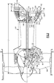
- a geared turbofan architecture with a counter-rotating low pressure compressor (LPC) 60 and counter-rotating low pressure turbine (LPT) 62 is provided, which significantly reduces a length of the low speed or inner shaft 40 as compared to a non-counter-rotating configuration, an example of which is shown in Figure 1 and in the upper half of Figure 2 .
- This non-rotating configuration in the upper half of Figure 2 is included for the purposes of a length comparison to the counter-rotating LPC and counter-rotating LPT configurations shown in the lower half of Figure 2 .
- the engine has a high pressure core, schematically indicated at 64.
- the high pressure core 64 includes the combustor 56 and the high spool 32 (i.e., the high pressure compressor 52, the high pressure turbine 54, and the high shaft 50) shown in Figure 1 .
- the high pressure compressor 52 has a high pressure core ratio of 23:1, for example. To retain this ratio, as well as providing a desired low shaft diameter and speed, a combination of the counter-rotating LPC 60 and LPT 62 is utilized as shown in the lower half of Figure 2 .
- the LPC 60 includes a counter-rotating compressor hub 70 with blade stages 72, 74, and 76 interspersed with blade stages 78 and 80 of the low speed spool 30.
- the counter-rotating compressor hub 70 may be driven by a transmission 82.
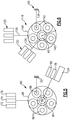
- the transmission 82 is also schematically illustrated in Figure 5 .
- the transmission 82 is an epicyclic transmission having a sun gear 84 mounted to the low shaft 40.
- a circumferential array of externally-toothed star gears 86 are in meshing engagement with the sun gear 84.
- the star gears 86 are carried on journals 88 carried by a carrier 90.
- the carrier 90 is fixedly mounted relative to an engine static structure 92.
- the static structure 92 is coupled to the low shaft 40 via multiple bearing systems 94 and 96 to permit rotation of the low shaft 40.
- the transmission 82 further includes an internally-toothed ring gear 98 encircling and in meshing engagement with the star gears 86.
- the ring gear 98 is supported relative to the static structure 92 by one or more bearing systems 100 and 102.
- the transmission 82 causes a counter-rotation of ring gear 98.
- Fan blades 104 of the fan section 22 are mounted via a hub 106 to the low shaft 40.
- low pressure compressor blades 78, 80 are also mounted to the hub 106 via a blade platform ring 108.
- the fan blades 104 and the low pressure compressor blades 78, 80 co-rotate with the low shaft 40.
- An outboard surface of the platform ring 108 locally forms an inboard boundary of a core flowpath 110.
- the blades of stages 78 and 80 extend from inboard ends fixed to the platform ring 108 to free outboard tips.
- the blades of the downstreammost stage 76 of the hub 70 are mounted to an outboard end of a support 112.
- the outboard ends of the blades of the stage 76 are secured relative to a shroud ring 114.
- An inboard surface of the shroud ring 114 forms a local outboard boundary of the core flowpath 110.
- the outboard ends of the blades of the stages 72 and 74 are mounted to the shroud ring 114.
- the support 112 is affixed to the ring gear 98 to drive rotation of the blades of stage 76 and, through the shroud ring 114, the blades of stages 72 and 74.
- the engine 20 without a counter-rotating compressor or turbine has an overall length L1 defined from a foremost surface of the fan blade 104 to an aftmost end of a turbine exhaust case 118.
- the LPC configuration 60 provides a length reduction L2 by utilizing a counter-rotating compressor architecture.
- the LPT configuration 62 provides another length reduction L3 by utilizing a counter-rotating turbine architecture.
- One example of a LPT is found in United States Publication No. 2009/0191045 A1 .
- Figures 2 and 4 show another example of a LPT 62 having a counter-rotating configuration with a gear system 116 mounted to the mid turbine frame 134.
- the gear system 116 is also schematically illustrated in Figure 6 .
- no turbine exhaust case 118 is needed, which further contributes to the overall amount of length reduction L3 by shortening the LPT static case portion.
- the LPT 62 has an inner set of blades 120 that are coupled to the low shaft 40 via the gear system 116 and an outer set of blades 122 interspersed with the inner set of blades 120.
- the number of stages in the inner set of blades 120 is equal to the number of stages in the outer set of blades 122.
- the outer set of blades 122 is directly coupled to the shaft 40.
- the outer blades 122 rotate in an opposite direction about the axis of rotation from the inner set of blades 120.
- the outer set of blades 122 is fixed to an outer rotor 126 that directly drives the low shaft 40, i.e. the low shaft 40 and outer set of blades 122 rotate at a common speed.
- the inner set of blades 120 is fixed to an inner rotor 124 that drives the gear system 116.
- Bearings 130, 132 rotatably support the inner rotor 124.
- Bearing 130 supports an aft end of the inner rotor 124 for rotation relative to the low shaft 40, and bearing 132 supports a fore end of the inner rotor 124 for rotation relative to the shaft 40.
- the aft bearing 130 is a ball bearing and the fore bearing 132 is a roller bearing.
- a bearing 146 supports the low shaft 140 for rotation relative to the mid-turbine frame 134.
- the shaft bearing 146 and the fore and aft bearings 132, 130 for the inner rotor 126 are axially spaced apart from each other parallel to the axis A.
- the shaft bearing 146 is located forward of the fore bearing 132.
- both bearings 132, 146 are roller bearings.
- a mid-turbine frame 134 comprises a static structure that extends to an outer case portion 136.
- the outer case portion 136 is attached to a fore end of a LPT static case 138, which surrounds the inner 120 and outer 122 sets of blades.
- An aft end of the LPT static case 138 is unsupported since there is no turbine exhaust case 118.
- the gear system 116 includes a sun gear 140 that is fixed for rotation with a fore end of the inner rotor 124.
- a circumferential array of externally-toothed star gears 142 are in meshing engagement with the sun gear 140.
- the star gears 142 are supported by a carrier 144 that is fixed to the mid-turbine frame 134.
- a ring gear 148 is in meshing engagement with the star gears 142 which are driven by the sun gear 140.
- the fore end of the inner rotor 124 drives the sun gear 140.
- the fore end of the outer rotor 126 is configured to be driven by the ring gear 148.
- the fore end of the outer rotor 126 is supported relative to the mid-turbine frame 134 by a bearing 150.
- the gear system has a ratio within a range of between about 0.5:1 and about 5.0:1.
- the gear system 116 is upstream or forward of the LPT 62. Specifically, the gear system 116 is positioned forward of the interspersed turbine blades 120, 122 and is surrounded by the mid-turbine frame. The carrier 144 for the star gears 142 is fixed to the mid-turbine frame 134.
- This counter-rotating configuration allows the overall length of the LPT static case 138 to be shortened compared to a non-counter-rotating configuration, and eliminates the need for a turbine exhaust case 118.
- the low shaft 40 receives a portion of the overall driving input directly from the outer set of turbine blades 122 and a remaining portion of the overall driving input is provided by the inner set of turbine blades 120 via the gear system 116.
- the outer set of turbine blades 122 is configured to rotate at a lower speed and in an opposite direction from the inner set of blades 120. Spinning the inner set of turbine blades 120 at a higher speed takes advantage of the existing turbine disks ability to handle higher speeds.
- This configuration provides a geared fan architecture with a long, slow turning low shaft 40, which enables the use of a high pressure ratio core. Further, this configuration provides for significant length reduction as compared to prior configurations.
- the fan 104 is connected to and directly driven by the shaft 40, thus rotating at the same speeds.
- the star gears 84, 140 are mounted to and directly coupled to the shaft 40.
- One set of compressor blades and one set of turbine blades (in the example, the inner compressor blades 78, 80 and outer turbine blades 122) are mounted to and directly coupled to the shaft 40.
- the carrier 90 and carrier 144 are grounded to the engine's static structure.
- the ring gears 98, 148 are respectively coupled to the other set of compressor and turbine blades (in the example, the outer compressor blades 72, 74, 76 and the inner turbine blades 120).
- the transmission 82 of the LPC 60 and the gear system 116 of the LPT 62 may be independently tailored to provide the desired speed for each of the set of inner compressor blades, set of outer compressor blades, set of inner turbine blades and set of outer turbine blades.
- the transmission 82 and gear system 116 have different ratios than one another. Since independent gear systems are provided for each of the LPC 60 and LPT 62, the gears and support structure can be smaller and lighter than, for example, a single fan drive gear system arranged at the front of the engine.
- approximately half of each of the LPC 60 and LPT 62 is directly connected to the shaft 40, only approximately half of the power must be transmitted through each of the transmission 82 and gear system 116.
- an engine has been invented that includes both a desirable high pressure core ratio, while at the same time reducing the overall engine length, thereby maximizing the engine's power density.
Applications Claiming Priority (2)
| Application Number | Priority Date | Filing Date | Title |
|---|---|---|---|
| US13/408,204 US20130219859A1 (en) | 2012-02-29 | 2012-02-29 | Counter rotating low pressure compressor and turbine each having a gear system |
| PCT/US2013/027550 WO2013187944A2 (en) | 2012-02-29 | 2013-02-25 | Counter rotating low pressure compressor and turbine each having a gear system |
Publications (3)
| Publication Number | Publication Date |
|---|---|
| EP2820267A2 EP2820267A2 (en) | 2015-01-07 |
| EP2820267A4 EP2820267A4 (en) | 2015-11-04 |
| EP2820267B1 true EP2820267B1 (en) | 2021-10-06 |
Family
ID=49001326
Family Applications (1)
| Application Number | Title | Priority Date | Filing Date |
|---|---|---|---|
| EP13804162.9A Active EP2820267B1 (en) | 2012-02-29 | 2013-02-25 | Counter rotating low pressure compressor and turbine each having a gear system |
Country Status (8)
| Country | Link |
|---|---|
| US (1) | US20130219859A1 (zh) |
| EP (1) | EP2820267B1 (zh) |
| JP (1) | JP5650263B2 (zh) |
| CN (1) | CN103291454B (zh) |
| BR (1) | BR102013001740A2 (zh) |
| CA (1) | CA2805186C (zh) |
| SG (1) | SG11201404226QA (zh) |
| WO (1) | WO2013187944A2 (zh) |
Families Citing this family (47)
| Publication number | Priority date | Publication date | Assignee | Title |
|---|---|---|---|---|
| US9976489B2 (en) | 2013-12-16 | 2018-05-22 | United Technologies Corporation | Gas turbine engine for long range aircraft |
| EP3108106B1 (en) | 2014-02-19 | 2022-05-04 | Raytheon Technologies Corporation | Gas turbine engine airfoil |
| EP3108121B1 (en) | 2014-02-19 | 2023-09-06 | Raytheon Technologies Corporation | Turbofan engine with geared architecture and lpc airfoils |
| US10385866B2 (en) | 2014-02-19 | 2019-08-20 | United Technologies Corporation | Gas turbine engine airfoil |
| WO2015126448A1 (en) * | 2014-02-19 | 2015-08-27 | United Technologies Corporation | Gas turbine engine airfoil |
| EP3108123B1 (en) | 2014-02-19 | 2023-10-04 | Raytheon Technologies Corporation | Turbofan engine with geared architecture and lpc airfoils |
| US10352331B2 (en) | 2014-02-19 | 2019-07-16 | United Technologies Corporation | Gas turbine engine airfoil |
| US10465702B2 (en) | 2014-02-19 | 2019-11-05 | United Technologies Corporation | Gas turbine engine airfoil |
| EP3108115B8 (en) | 2014-02-19 | 2023-11-08 | RTX Corporation | Turbofan engine with geared architecture and lpc blades |
| EP3108107B1 (en) | 2014-02-19 | 2023-10-11 | Raytheon Technologies Corporation | Turbofan engine with geared architecture and lpc airfoils |
| US10502229B2 (en) * | 2014-02-19 | 2019-12-10 | United Technologies Corporation | Gas turbine engine airfoil |
| WO2015126941A1 (en) | 2014-02-19 | 2015-08-27 | United Technologies Corporation | Gas turbine engine airfoil |
| EP3108113A4 (en) | 2014-02-19 | 2017-03-15 | United Technologies Corporation | Gas turbine engine airfoil |
| US10393139B2 (en) | 2014-02-19 | 2019-08-27 | United Technologies Corporation | Gas turbine engine airfoil |
| WO2015175052A2 (en) | 2014-02-19 | 2015-11-19 | United Technologies Corporation | Gas turbine engine airfoil |
| EP3108120B1 (en) | 2014-02-19 | 2021-03-31 | Raytheon Technologies Corporation | Gas turbine engine having a geared architecture and a specific fixed airfoil structure |
| WO2015126450A1 (en) | 2014-02-19 | 2015-08-27 | United Technologies Corporation | Gas turbine engine airfoil |
| US10519971B2 (en) | 2014-02-19 | 2019-12-31 | United Technologies Corporation | Gas turbine engine airfoil |
| FR3018094B1 (fr) * | 2014-02-28 | 2021-12-03 | Snecma | Rotor de soufflante pour une turbomachine telle qu'un turboreacteur multiflux entraine par reducteur |
| US9869190B2 (en) | 2014-05-30 | 2018-01-16 | General Electric Company | Variable-pitch rotor with remote counterweights |
| US9410430B2 (en) | 2014-06-19 | 2016-08-09 | Jay HASKIN | Turbine apparatus with counter-rotating blades |
| BE1022364B1 (fr) * | 2014-10-27 | 2016-03-17 | Techspace Aero S.A. | Compresseur de turbomachine axiale avec double rotors contrarotatifs |
| US9982676B2 (en) | 2014-11-18 | 2018-05-29 | Rolls-Royce North American Technologies Inc. | Split axial-centrifugal compressor |
| US10329943B2 (en) | 2014-11-18 | 2019-06-25 | Rolls-Royce North American Technologies Inc. | Split axial-centrifugal compressor |
| US10072510B2 (en) | 2014-11-21 | 2018-09-11 | General Electric Company | Variable pitch fan for gas turbine engine and method of assembling the same |
| US10100653B2 (en) | 2015-10-08 | 2018-10-16 | General Electric Company | Variable pitch fan blade retention system |
| US10508562B2 (en) * | 2015-12-01 | 2019-12-17 | United Technologies Corporation | Geared turbofan with four star/planetary gear reduction |
| US10260367B2 (en) | 2016-11-02 | 2019-04-16 | Jay HASKIN | Power transmission system for turbines or compressors having counter-rotating blades |
| US9745860B1 (en) * | 2016-11-02 | 2017-08-29 | Jay HASKIN | Power transmission system for turbine or compressor having counter-rotating blades |
| US10801442B2 (en) | 2017-02-08 | 2020-10-13 | General Electric Company | Counter rotating turbine with reversing reduction gear assembly |
| US10465606B2 (en) * | 2017-02-08 | 2019-11-05 | General Electric Company | Counter rotating turbine with reversing reduction gearbox |
| US10823114B2 (en) | 2017-02-08 | 2020-11-03 | General Electric Company | Counter rotating turbine with reversing reduction gearbox |
| US10654577B2 (en) * | 2017-02-22 | 2020-05-19 | General Electric Company | Rainbow flowpath low pressure turbine rotor assembly |
| DE102017211649A1 (de) * | 2017-07-07 | 2019-01-10 | MTU Aero Engines AG | Gasturbine mit einer schnelllaufenden Niederdruckturbine und einem Turbinengehäuse |
| US10738617B2 (en) | 2017-09-20 | 2020-08-11 | General Electric Company | Turbomachine with alternatingly spaced turbine rotor blades |
| US10508546B2 (en) | 2017-09-20 | 2019-12-17 | General Electric Company | Turbomachine with alternatingly spaced turbine rotor blades |
| US10823000B2 (en) | 2017-09-20 | 2020-11-03 | General Electric Company | Turbomachine with alternatingly spaced turbine rotor blades |
| US11098592B2 (en) | 2017-09-20 | 2021-08-24 | General Electric Company | Turbomachine with alternatingly spaced turbine rotor blades |
| US10914194B2 (en) * | 2017-09-20 | 2021-02-09 | General Electric Company | Turbomachine with alternatingly spaced turbine rotor blades |
| US10823001B2 (en) | 2017-09-20 | 2020-11-03 | General Electric Company | Turbomachine with alternatingly spaced turbine rotor blades |
| US10781717B2 (en) | 2017-09-20 | 2020-09-22 | General Electric Company | Turbomachine with alternatingly spaced turbine rotor blades |
| EP3578763A1 (en) | 2018-06-07 | 2019-12-11 | Haskin, Jay | Power transmission system for turbine, a turbocharger, a compressor, or a pump |
| GB201812553D0 (en) * | 2018-08-01 | 2018-09-12 | Rolls Royce Plc | Gas turbine engine |
| US11118535B2 (en) | 2019-03-05 | 2021-09-14 | General Electric Company | Reversing gear assembly for a turbo machine |
| US11428160B2 (en) | 2020-12-31 | 2022-08-30 | General Electric Company | Gas turbine engine with interdigitated turbine and gear assembly |
| US11674435B2 (en) | 2021-06-29 | 2023-06-13 | General Electric Company | Levered counterweight feathering system |
| US11795964B2 (en) | 2021-07-16 | 2023-10-24 | General Electric Company | Levered counterweight feathering system |
Family Cites Families (31)
| Publication number | Priority date | Publication date | Assignee | Title |
|---|---|---|---|---|
| US2702985A (en) * | 1944-01-31 | 1955-03-01 | Power Jets Res & Dev Ltd | Gas turbine power plant with power take-off from rotatable guide blading |
| US3673802A (en) * | 1970-06-18 | 1972-07-04 | Gen Electric | Fan engine with counter rotating geared core booster |
| GB1309721A (en) * | 1971-01-08 | 1973-03-14 | Secr Defence | Fan |
| US4251987A (en) * | 1979-08-22 | 1981-02-24 | General Electric Company | Differential geared engine |
| US4817382A (en) * | 1985-12-31 | 1989-04-04 | The Boeing Company | Turboprop propulsion apparatus |
| US4860537A (en) * | 1986-08-29 | 1989-08-29 | Brandt, Inc. | High bypass ratio counterrotating gearless front fan engine |
| GB2195712B (en) * | 1986-10-08 | 1990-08-29 | Rolls Royce Plc | A turbofan gas turbine engine |
| US4936748A (en) * | 1988-11-28 | 1990-06-26 | General Electric Company | Auxiliary power source in an unducted fan gas turbine engine |
| US5010729A (en) * | 1989-01-03 | 1991-04-30 | General Electric Company | Geared counterrotating turbine/fan propulsion system |
| US4969325A (en) * | 1989-01-03 | 1990-11-13 | General Electric Company | Turbofan engine having a counterrotating partially geared fan drive turbine |
| US5361580A (en) * | 1993-06-18 | 1994-11-08 | General Electric Company | Gas turbine engine rotor support system |
| US5307622A (en) * | 1993-08-02 | 1994-05-03 | General Electric Company | Counterrotating turbine support assembly |
| US6158210A (en) * | 1998-12-03 | 2000-12-12 | General Electric Company | Gear driven booster |
| GB0406174D0 (en) * | 2004-03-19 | 2004-04-21 | Rolls Royce Plc | Turbine engine arrangement |
| US7334392B2 (en) * | 2004-10-29 | 2008-02-26 | General Electric Company | Counter-rotating gas turbine engine and method of assembling same |
| US7752836B2 (en) * | 2005-10-19 | 2010-07-13 | General Electric Company | Gas turbine assembly and methods of assembling same |
| US7950220B2 (en) * | 2006-06-19 | 2011-05-31 | United Technologies Corporation | Turbine engine compressor |
| US7704178B2 (en) * | 2006-07-05 | 2010-04-27 | United Technologies Corporation | Oil baffle for gas turbine fan drive gear system |
| US7966806B2 (en) * | 2006-10-31 | 2011-06-28 | General Electric Company | Turbofan engine assembly and method of assembling same |
| US8015798B2 (en) * | 2007-12-13 | 2011-09-13 | United Technologies Corporation | Geared counter-rotating gas turbofan engine |
| US8292570B2 (en) * | 2008-01-25 | 2012-10-23 | United Technologies Corporation | Low pressure turbine with counter-rotating drives for single spool |
| FR2940247B1 (fr) * | 2008-12-19 | 2011-01-21 | Snecma | Systeme d'helices contrarotatives entrainees par un train epicycloidal offrant une repartition de couple equilibree entre les deux helices |
| US8191352B2 (en) * | 2008-12-19 | 2012-06-05 | General Electric Company | Geared differential speed counter-rotatable low pressure turbine |
| FR2942203B1 (fr) * | 2009-02-13 | 2011-04-22 | Snecma | Systeme d'helices contrarotatives a encombrement reduit |
| US8375695B2 (en) * | 2009-06-30 | 2013-02-19 | General Electric Company | Aircraft gas turbine engine counter-rotatable generator |
| FR2950381B1 (fr) * | 2009-09-18 | 2011-10-28 | Snecma | Turbomachine a helices non carenees contrarotatives |
| FR2955085B1 (fr) * | 2010-01-08 | 2011-12-23 | Snecma | Systeme d'helices contrarotatives pour turbomachine d'aeronef |
| US9022725B2 (en) * | 2012-02-29 | 2015-05-05 | United Technologies Corporation | Counter-rotating low pressure turbine with gear system mounted to turbine exhaust case |
| US9080512B2 (en) * | 2012-02-29 | 2015-07-14 | United Technologies Corporation | Counter-rotating low pressure turbine with gear system mounted to mid turbine frame |
| US9028200B2 (en) * | 2012-02-29 | 2015-05-12 | United Technologies Corporation | Counter rotating low pressure turbine with splitter gear system |
| US9011076B2 (en) * | 2012-02-29 | 2015-04-21 | United Technologies Corporation | Counter-rotating low pressure turbine with gear system mounted to turbine exhaust case |
-
2012
- 2012-02-29 US US13/408,204 patent/US20130219859A1/en not_active Abandoned
-
2013
- 2013-01-23 BR BRBR102013001740-0A patent/BR102013001740A2/pt not_active Application Discontinuation
- 2013-02-06 CA CA2805186A patent/CA2805186C/en active Active
- 2013-02-25 WO PCT/US2013/027550 patent/WO2013187944A2/en active Application Filing
- 2013-02-25 EP EP13804162.9A patent/EP2820267B1/en active Active
- 2013-02-25 SG SG11201404226QA patent/SG11201404226QA/en unknown
- 2013-02-28 CN CN201310063503.9A patent/CN103291454B/zh active Active
- 2013-02-28 JP JP2013038266A patent/JP5650263B2/ja active Active
Non-Patent Citations (1)
| Title |
|---|
| None * |
Also Published As
| Publication number | Publication date |
|---|---|
| EP2820267A4 (en) | 2015-11-04 |
| US20130219859A1 (en) | 2013-08-29 |
| WO2013187944A2 (en) | 2013-12-19 |
| CN103291454B (zh) | 2016-01-06 |
| CN103291454A (zh) | 2013-09-11 |
| SG11201404226QA (en) | 2014-10-30 |
| CA2805186C (en) | 2016-03-29 |
| WO2013187944A3 (en) | 2014-02-13 |
| JP5650263B2 (ja) | 2015-01-07 |
| BR102013001740A2 (pt) | 2015-05-12 |
| JP2013181541A (ja) | 2013-09-12 |
| CA2805186A1 (en) | 2013-08-29 |
| EP2820267A2 (en) | 2015-01-07 |
Similar Documents
| Publication | Publication Date | Title |
|---|---|---|
| EP2820267B1 (en) | Counter rotating low pressure compressor and turbine each having a gear system | |
| EP2820282B1 (en) | Counter-rotating low pressure turbine with gear system mounted to mid turbine frame | |
| EP2820265B1 (en) | Counter rotating low pressure turbine with splitter gear system | |
| EP2820266B1 (en) | Gas turbine engine | |
| EP2820280B1 (en) | Counter-rotating low pressure turbine with gear system mounted to turbine exhaust case | |
| EP2820281B1 (en) | Counter-rotating low pressure turbine without turbine exhaust case | |
| EP2877725B1 (en) | Geared fan with inner counter rotating compressor | |
| EP3036416B1 (en) | High thrust geared gas turbine engine | |
| EP3808964B1 (en) | Geared turbofan with non-epicyclic gear reduction system | |
| EP3054141B1 (en) | Gear reduction for geared turbofan | |
| EP2855874B1 (en) | Gas turbine engine with a counter rotating fan | |
| EP3165755A1 (en) | Gas turbine engine with high speed low pressure turbine section and bearing support features | |
| EP3163033A1 (en) | Gas turbine engine with high speed low pressure turbine section and bearing support features | |
| EP3165754A1 (en) | Gas turbine engine with high speed low pressure turbine section and bearing support features | |
| EP3165753A1 (en) | Gas turbine engine with mount for low pressure turbine section | |
| EP3163062A1 (en) | Gas turbine engine with high speed low pressure turbine section and bearing support features |
Legal Events
| Date | Code | Title | Description |
|---|---|---|---|
| PUAI | Public reference made under article 153(3) epc to a published international application that has entered the european phase |
Free format text: ORIGINAL CODE: 0009012 |
|
| 17P | Request for examination filed |
Effective date: 20140925 |
|
| AK | Designated contracting states |
Kind code of ref document: A2 Designated state(s): AL AT BE BG CH CY CZ DE DK EE ES FI FR GB GR HR HU IE IS IT LI LT LU LV MC MK MT NL NO PL PT RO RS SE SI SK SM TR |
|
| AX | Request for extension of the european patent |
Extension state: BA ME |
|
| DAX | Request for extension of the european patent (deleted) | ||
| A4 | Supplementary search report drawn up and despatched |
Effective date: 20151001 |
|
| RIC1 | Information provided on ipc code assigned before grant |
Ipc: F02K 3/072 20060101ALI20150925BHEP Ipc: F02C 7/36 20060101ALI20150925BHEP Ipc: F02C 3/067 20060101AFI20150925BHEP |
|
| RAP1 | Party data changed (applicant data changed or rights of an application transferred) |
Owner name: UNITED TECHNOLOGIES CORPORATION |
|
| STAA | Information on the status of an ep patent application or granted ep patent |
Free format text: STATUS: EXAMINATION IS IN PROGRESS |
|
| 17Q | First examination report despatched |
Effective date: 20180912 |
|
| STAA | Information on the status of an ep patent application or granted ep patent |
Free format text: STATUS: EXAMINATION IS IN PROGRESS |
|
| RAP1 | Party data changed (applicant data changed or rights of an application transferred) |
Owner name: RAYTHEON TECHNOLOGIES CORPORATION |
|
| GRAP | Despatch of communication of intention to grant a patent |
Free format text: ORIGINAL CODE: EPIDOSNIGR1 |
|
| STAA | Information on the status of an ep patent application or granted ep patent |
Free format text: STATUS: GRANT OF PATENT IS INTENDED |
|
| RIC1 | Information provided on ipc code assigned before grant |
Ipc: F02C 3/067 20060101AFI20210324BHEP Ipc: F02K 3/072 20060101ALI20210324BHEP Ipc: F02C 7/36 20060101ALI20210324BHEP Ipc: F02C 3/113 20060101ALI20210324BHEP |
|
| INTG | Intention to grant announced |
Effective date: 20210419 |
|
| GRAS | Grant fee paid |
Free format text: ORIGINAL CODE: EPIDOSNIGR3 |
|
| GRAA | (expected) grant |
Free format text: ORIGINAL CODE: 0009210 |
|
| STAA | Information on the status of an ep patent application or granted ep patent |
Free format text: STATUS: THE PATENT HAS BEEN GRANTED |
|
| AK | Designated contracting states |
Kind code of ref document: B1 Designated state(s): AL AT BE BG CH CY CZ DE DK EE ES FI FR GB GR HR HU IE IS IT LI LT LU LV MC MK MT NL NO PL PT RO RS SE SI SK SM TR |
|
| REG | Reference to a national code |
Ref country code: GB Ref legal event code: FG4D |
|
| REG | Reference to a national code |
Ref country code: CH Ref legal event code: EP Ref country code: AT Ref legal event code: REF Ref document number: 1436421 Country of ref document: AT Kind code of ref document: T Effective date: 20211015 |
|
| REG | Reference to a national code |
Ref country code: IE Ref legal event code: FG4D |
|
| REG | Reference to a national code |
Ref country code: DE Ref legal event code: R096 Ref document number: 602013079562 Country of ref document: DE |
|
| REG | Reference to a national code |
Ref country code: LT Ref legal event code: MG9D |
|
| REG | Reference to a national code |
Ref country code: NL Ref legal event code: MP Effective date: 20211006 |
|
| REG | Reference to a national code |
Ref country code: AT Ref legal event code: MK05 Ref document number: 1436421 Country of ref document: AT Kind code of ref document: T Effective date: 20211006 |
|
| PG25 | Lapsed in a contracting state [announced via postgrant information from national office to epo] |
Ref country code: RS Free format text: LAPSE BECAUSE OF FAILURE TO SUBMIT A TRANSLATION OF THE DESCRIPTION OR TO PAY THE FEE WITHIN THE PRESCRIBED TIME-LIMIT Effective date: 20211006 Ref country code: LT Free format text: LAPSE BECAUSE OF FAILURE TO SUBMIT A TRANSLATION OF THE DESCRIPTION OR TO PAY THE FEE WITHIN THE PRESCRIBED TIME-LIMIT Effective date: 20211006 Ref country code: FI Free format text: LAPSE BECAUSE OF FAILURE TO SUBMIT A TRANSLATION OF THE DESCRIPTION OR TO PAY THE FEE WITHIN THE PRESCRIBED TIME-LIMIT Effective date: 20211006 Ref country code: BG Free format text: LAPSE BECAUSE OF FAILURE TO SUBMIT A TRANSLATION OF THE DESCRIPTION OR TO PAY THE FEE WITHIN THE PRESCRIBED TIME-LIMIT Effective date: 20220106 Ref country code: AT Free format text: LAPSE BECAUSE OF FAILURE TO SUBMIT A TRANSLATION OF THE DESCRIPTION OR TO PAY THE FEE WITHIN THE PRESCRIBED TIME-LIMIT Effective date: 20211006 |
|
| PG25 | Lapsed in a contracting state [announced via postgrant information from national office to epo] |
Ref country code: IS Free format text: LAPSE BECAUSE OF FAILURE TO SUBMIT A TRANSLATION OF THE DESCRIPTION OR TO PAY THE FEE WITHIN THE PRESCRIBED TIME-LIMIT Effective date: 20220206 Ref country code: SE Free format text: LAPSE BECAUSE OF FAILURE TO SUBMIT A TRANSLATION OF THE DESCRIPTION OR TO PAY THE FEE WITHIN THE PRESCRIBED TIME-LIMIT Effective date: 20211006 Ref country code: PT Free format text: LAPSE BECAUSE OF FAILURE TO SUBMIT A TRANSLATION OF THE DESCRIPTION OR TO PAY THE FEE WITHIN THE PRESCRIBED TIME-LIMIT Effective date: 20220207 Ref country code: PL Free format text: LAPSE BECAUSE OF FAILURE TO SUBMIT A TRANSLATION OF THE DESCRIPTION OR TO PAY THE FEE WITHIN THE PRESCRIBED TIME-LIMIT Effective date: 20211006 Ref country code: NO Free format text: LAPSE BECAUSE OF FAILURE TO SUBMIT A TRANSLATION OF THE DESCRIPTION OR TO PAY THE FEE WITHIN THE PRESCRIBED TIME-LIMIT Effective date: 20220106 Ref country code: NL Free format text: LAPSE BECAUSE OF FAILURE TO SUBMIT A TRANSLATION OF THE DESCRIPTION OR TO PAY THE FEE WITHIN THE PRESCRIBED TIME-LIMIT Effective date: 20211006 Ref country code: LV Free format text: LAPSE BECAUSE OF FAILURE TO SUBMIT A TRANSLATION OF THE DESCRIPTION OR TO PAY THE FEE WITHIN THE PRESCRIBED TIME-LIMIT Effective date: 20211006 Ref country code: HR Free format text: LAPSE BECAUSE OF FAILURE TO SUBMIT A TRANSLATION OF THE DESCRIPTION OR TO PAY THE FEE WITHIN THE PRESCRIBED TIME-LIMIT Effective date: 20211006 Ref country code: GR Free format text: LAPSE BECAUSE OF FAILURE TO SUBMIT A TRANSLATION OF THE DESCRIPTION OR TO PAY THE FEE WITHIN THE PRESCRIBED TIME-LIMIT Effective date: 20220107 Ref country code: ES Free format text: LAPSE BECAUSE OF FAILURE TO SUBMIT A TRANSLATION OF THE DESCRIPTION OR TO PAY THE FEE WITHIN THE PRESCRIBED TIME-LIMIT Effective date: 20211006 |
|
| REG | Reference to a national code |
Ref country code: DE Ref legal event code: R097 Ref document number: 602013079562 Country of ref document: DE |
|
| PG25 | Lapsed in a contracting state [announced via postgrant information from national office to epo] |
Ref country code: SM Free format text: LAPSE BECAUSE OF FAILURE TO SUBMIT A TRANSLATION OF THE DESCRIPTION OR TO PAY THE FEE WITHIN THE PRESCRIBED TIME-LIMIT Effective date: 20211006 Ref country code: SK Free format text: LAPSE BECAUSE OF FAILURE TO SUBMIT A TRANSLATION OF THE DESCRIPTION OR TO PAY THE FEE WITHIN THE PRESCRIBED TIME-LIMIT Effective date: 20211006 Ref country code: RO Free format text: LAPSE BECAUSE OF FAILURE TO SUBMIT A TRANSLATION OF THE DESCRIPTION OR TO PAY THE FEE WITHIN THE PRESCRIBED TIME-LIMIT Effective date: 20211006 Ref country code: EE Free format text: LAPSE BECAUSE OF FAILURE TO SUBMIT A TRANSLATION OF THE DESCRIPTION OR TO PAY THE FEE WITHIN THE PRESCRIBED TIME-LIMIT Effective date: 20211006 Ref country code: DK Free format text: LAPSE BECAUSE OF FAILURE TO SUBMIT A TRANSLATION OF THE DESCRIPTION OR TO PAY THE FEE WITHIN THE PRESCRIBED TIME-LIMIT Effective date: 20211006 Ref country code: CZ Free format text: LAPSE BECAUSE OF FAILURE TO SUBMIT A TRANSLATION OF THE DESCRIPTION OR TO PAY THE FEE WITHIN THE PRESCRIBED TIME-LIMIT Effective date: 20211006 |
|
| PLBE | No opposition filed within time limit |
Free format text: ORIGINAL CODE: 0009261 |
|
| STAA | Information on the status of an ep patent application or granted ep patent |
Free format text: STATUS: NO OPPOSITION FILED WITHIN TIME LIMIT |
|
| 26N | No opposition filed |
Effective date: 20220707 |
|
| PG25 | Lapsed in a contracting state [announced via postgrant information from national office to epo] |
Ref country code: MC Free format text: LAPSE BECAUSE OF FAILURE TO SUBMIT A TRANSLATION OF THE DESCRIPTION OR TO PAY THE FEE WITHIN THE PRESCRIBED TIME-LIMIT Effective date: 20211006 |
|
| REG | Reference to a national code |
Ref country code: CH Ref legal event code: PL |
|
| REG | Reference to a national code |
Ref country code: BE Ref legal event code: MM Effective date: 20220228 |
|
| PG25 | Lapsed in a contracting state [announced via postgrant information from national office to epo] |
Ref country code: LU Free format text: LAPSE BECAUSE OF NON-PAYMENT OF DUE FEES Effective date: 20220225 Ref country code: AL Free format text: LAPSE BECAUSE OF FAILURE TO SUBMIT A TRANSLATION OF THE DESCRIPTION OR TO PAY THE FEE WITHIN THE PRESCRIBED TIME-LIMIT Effective date: 20211006 |
|
| PG25 | Lapsed in a contracting state [announced via postgrant information from national office to epo] |
Ref country code: SI Free format text: LAPSE BECAUSE OF FAILURE TO SUBMIT A TRANSLATION OF THE DESCRIPTION OR TO PAY THE FEE WITHIN THE PRESCRIBED TIME-LIMIT Effective date: 20211006 |
|
| PG25 | Lapsed in a contracting state [announced via postgrant information from national office to epo] |
Ref country code: LI Free format text: LAPSE BECAUSE OF NON-PAYMENT OF DUE FEES Effective date: 20220228 Ref country code: IE Free format text: LAPSE BECAUSE OF NON-PAYMENT OF DUE FEES Effective date: 20220225 Ref country code: CH Free format text: LAPSE BECAUSE OF NON-PAYMENT OF DUE FEES Effective date: 20220228 |
|
| PG25 | Lapsed in a contracting state [announced via postgrant information from national office to epo] |
Ref country code: BE Free format text: LAPSE BECAUSE OF NON-PAYMENT OF DUE FEES Effective date: 20220228 |
|
| PGFP | Annual fee paid to national office [announced via postgrant information from national office to epo] |
Ref country code: FR Payment date: 20230119 Year of fee payment: 11 |
|
| PG25 | Lapsed in a contracting state [announced via postgrant information from national office to epo] |
Ref country code: IT Free format text: LAPSE BECAUSE OF FAILURE TO SUBMIT A TRANSLATION OF THE DESCRIPTION OR TO PAY THE FEE WITHIN THE PRESCRIBED TIME-LIMIT Effective date: 20211006 |
|
| PGFP | Annual fee paid to national office [announced via postgrant information from national office to epo] |
Ref country code: GB Payment date: 20230120 Year of fee payment: 11 Ref country code: DE Payment date: 20230119 Year of fee payment: 11 |
|
| P01 | Opt-out of the competence of the unified patent court (upc) registered |
Effective date: 20230520 |
|
| PG25 | Lapsed in a contracting state [announced via postgrant information from national office to epo] |
Ref country code: HU Free format text: LAPSE BECAUSE OF FAILURE TO SUBMIT A TRANSLATION OF THE DESCRIPTION OR TO PAY THE FEE WITHIN THE PRESCRIBED TIME-LIMIT; INVALID AB INITIO Effective date: 20130225 |