EP2819427A1 - Microphone device - Google Patents
Microphone device Download PDFInfo
- Publication number
- EP2819427A1 EP2819427A1 EP13752212.4A EP13752212A EP2819427A1 EP 2819427 A1 EP2819427 A1 EP 2819427A1 EP 13752212 A EP13752212 A EP 13752212A EP 2819427 A1 EP2819427 A1 EP 2819427A1
- Authority
- EP
- European Patent Office
- Prior art keywords
- opening section
- upper face
- microphone device
- microphone
- housing
- Prior art date
- Legal status (The legal status is an assumption and is not a legal conclusion. Google has not performed a legal analysis and makes no representation as to the accuracy of the status listed.)
- Granted
Links
Images




Classifications
-
- H—ELECTRICITY
- H04—ELECTRIC COMMUNICATION TECHNIQUE
- H04R—LOUDSPEAKERS, MICROPHONES, GRAMOPHONE PICK-UPS OR LIKE ACOUSTIC ELECTROMECHANICAL TRANSDUCERS; ELECTRIC HEARING AIDS; PUBLIC ADDRESS SYSTEMS
- H04R1/00—Details of transducers, loudspeakers or microphones
- H04R1/20—Arrangements for obtaining desired frequency or directional characteristics
- H04R1/22—Arrangements for obtaining desired frequency or directional characteristics for obtaining desired frequency characteristic only
- H04R1/222—Arrangements for obtaining desired frequency or directional characteristics for obtaining desired frequency characteristic only for microphones
-
- H—ELECTRICITY
- H04—ELECTRIC COMMUNICATION TECHNIQUE
- H04R—LOUDSPEAKERS, MICROPHONES, GRAMOPHONE PICK-UPS OR LIKE ACOUSTIC ELECTROMECHANICAL TRANSDUCERS; ELECTRIC HEARING AIDS; PUBLIC ADDRESS SYSTEMS
- H04R1/00—Details of transducers, loudspeakers or microphones
- H04R1/02—Casings; Cabinets ; Supports therefor; Mountings therein
- H04R1/021—Casings; Cabinets ; Supports therefor; Mountings therein incorporating only one transducer
-
- H—ELECTRICITY
- H04—ELECTRIC COMMUNICATION TECHNIQUE
- H04R—LOUDSPEAKERS, MICROPHONES, GRAMOPHONE PICK-UPS OR LIKE ACOUSTIC ELECTROMECHANICAL TRANSDUCERS; ELECTRIC HEARING AIDS; PUBLIC ADDRESS SYSTEMS
- H04R1/00—Details of transducers, loudspeakers or microphones
- H04R1/08—Mouthpieces; Microphones; Attachments therefor
- H04R1/083—Special constructions of mouthpieces
-
- H—ELECTRICITY
- H04—ELECTRIC COMMUNICATION TECHNIQUE
- H04R—LOUDSPEAKERS, MICROPHONES, GRAMOPHONE PICK-UPS OR LIKE ACOUSTIC ELECTROMECHANICAL TRANSDUCERS; ELECTRIC HEARING AIDS; PUBLIC ADDRESS SYSTEMS
- H04R1/00—Details of transducers, loudspeakers or microphones
- H04R1/20—Arrangements for obtaining desired frequency or directional characteristics
- H04R1/32—Arrangements for obtaining desired frequency or directional characteristics for obtaining desired directional characteristic only
- H04R1/34—Arrangements for obtaining desired frequency or directional characteristics for obtaining desired directional characteristic only by using a single transducer with sound reflecting, diffracting, directing or guiding means
- H04R1/342—Arrangements for obtaining desired frequency or directional characteristics for obtaining desired directional characteristic only by using a single transducer with sound reflecting, diffracting, directing or guiding means for microphones
-
- H—ELECTRICITY
- H04—ELECTRIC COMMUNICATION TECHNIQUE
- H04R—LOUDSPEAKERS, MICROPHONES, GRAMOPHONE PICK-UPS OR LIKE ACOUSTIC ELECTROMECHANICAL TRANSDUCERS; ELECTRIC HEARING AIDS; PUBLIC ADDRESS SYSTEMS
- H04R29/00—Monitoring arrangements; Testing arrangements
- H04R29/004—Monitoring arrangements; Testing arrangements for microphones
Definitions
- the present invention relates to a microphone device configured to reduce fluctuations in frequency characteristics due to diffracted sound and reflected sound.
- FIG. 1 is an external view showing a microphone device 100 having been used conventionally for this measurement.
- This microphone device 100 has a housing being composed of a disc-shaped base section 101 and a neck 102 provided upright at the center of this base section 101. At the top of the neck 102, an opening section 102A is provided, and inside the neck 102, a microphone unit 103 is incorporated toward the opening section 102A.
- the microphone device 100 is placed at a listening point, test sound is emitted from the speaker, and the test sound picked up by the microphone device 100 is analyzed to determine the acoustic characteristics of the speaker and the listening room.
- FIG. 2 a technique wherein a microphone base 110 having three concave sections 101 is placed at a listening point, the microphone device 100 is mounted sequentially in the three concave sections 101, and test sound is picked up sequentially to measure the acoustic characteristics of the listening room three-dimensionally has also been put into practical use.
- Patent Document 1 JP-A-2009-37143
- the frequency characteristics of the microphone device for use in the above-mentioned measurement are desired to be flat.
- diffracted-reflected sound due to the edge of the base section 101 of the housing and reflected sound reflected by the microphone base 110 in the case that the microphone device 100 is placed on the microphone base 110 are picked up together with direct sound as shown in FIG. 3 , and the frequency characteristics do not become flat because of interference due to the distance differences between the direct sound and the diffracted-reflected sound and between the direct sound and the reflected sound, thereby causing a problem that errors occur in the results of the measurement.
- the diffracted-reflected sound is herein the sound obtained in the case that the reflected sound from the surface of the microphone device 100 is diffracted (diffraction) and picked up by the microphone unit 103, and the sound is hereafter referred to as "diffracted-reflected sound (due to the edge)" because the contribution of the diffraction from the edge is dominant to the fluctuations in the characteristics due to interference.
- the present invention is intended to provide a microphone configured to suppress fluctuations in frequency characteristics due to diffraction and reflection as much as possible.
- the present invention is a microphone device comprising: a housing having an opening section in an upper face thereof; and a non-directional microphone unit incorporated in the housing and provided inside the opening section, wherein the upper face of the housing has a shape in which a distance from an edge defined as a boundary between the upper face and a side face or a bottom face to the opening section throughout a whole circumference of the upper face changes in 1/2 or more of the whole circumference of the edge and an average value of the distance from the edge to the opening section is shorter than 1/2 of the wavelength of a sound wave in a frequency range in which an auditory sensitivity of humans is low.
- the frequency range in which the auditory sensitivity of humans is low may be 10 kHz.
- a ratio of a longest distance to a shortest distance, from the edge to the opening section, may be two or more.
- the opening section may be provided at a center of a circumscribed circle of a planar shape of the upper face.
- a planar shape of the upper face may be a triangle.
- the influence of diffracted sound and reflected sound on the frequency characteristics of the sound picked up by the microphone unit can be suppressed to the minimum.
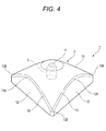
- FIG. 4 is an external view showing a microphone device 1 according to an embodiment of the present invention.
- This microphone device 1 is used as a measurement microphone for measuring the acoustic characteristics of an audio system and a listening room.
- the microphone device 1 has a housing 2 and a microphone unit 3 incorporated in the housing 2.
- the planar shape of the housing 2 (the microphone device 1) is a nearly equilateral triangle, and its overall shape is such a shape as obtained by vertically cutting off a gently sloping cone so that the shape matches the planar shape of the above-mentioned nearly equilateral triangle.
- the upper face 10 of the housing 2 has an opening section 11 at the center and is inclined downward toward sides 13 serving as peripheral edges (edges) with the opening section 11 as an apex.
- the upper face 10 on the side 13 is a curved face being highest at an intermediate point 13A nearest from the opening section 11 and lowest at apexes 13B farthest from the opening section 11.
- the side face 12 formed vertically downward from the side 13 of the upper face 10 is an arch-shaped plane being highest at the center portion, that is, the intermediate point 13A, and lowest at both ends, that is, the apexes 13B.
- the non-directional microphone unit 3 is provided upward.
- the distance of the side (edge) of the upper face 10 from the opening section 11 is not constant.
- the distance (to the opening section 11) changes gradually, and the ratio between the distance to the nearest point (the intermediate point 13A) and the distance to the farthest points (the apex 13B) is approximately 1:2.5.
- the dimension from the center portion of the opening section 11 to the apex 13B is approximately 2 cm
- the dimension from the center portion of the opening section 11 to the intermediate point 13A is approximately 1 cm
- the height of the microphone device 1 is approximately 1.5 cm.
- the audible range of humans is 20 Hz to 20 kHz.
- the sensitivity of human ears is high for the sound in a frequency range of 2 kHz to 4 kHz, and the sound in this range is easy to hear.
- the sensitivity lowers depending on the level of a signal, and humans gradually become unaware of sound; for example, it is difficult to hear the sound in a frequency range around 10 kHz and humans become unaware of the sound.
- the frequency is, for example, approximately 10 kHz or more, it is assumed that the influence on acoustic feeling is negligible in practice.
- FIG. 5D and FIG. 6D are graphs showing the frequency characteristics of the microphone device 1 shown in FIG. 4 .
- FIGS. 5A to 5D are graphs showing the frequency characteristics in the case that the microphone device 1 is placed in the air
- These figures also show, as comparison examples, the characteristics ( FIGS. 5A and 6A ) of the microphone device having the conventional shape shown in FIG. 1 , the characteristics ( FIGS.
- FIGS. 5B and 6B the characteristics ( FIGS. 5C and 6C ) of a microphone device having a shape with a pedestal having a quadrangular planar shape and with a longer neck.
- FIGS. 5A to 5D show the frequency characteristics in the case that the microphone device 1 is placed in the air, it is assumed that only the diffracted-reflected sound due to the housing 2, more particularly, the side (edge) 13, affects the frequency characteristics of the sound signal picked up by the microphone unit 20.
- the characteristics of sounds arriving from any directions are changed at 2 kHz or more, and the changes in the characteristics are not the same depending on the arrival angle. Furthermore, in the sound arriving from the 20 degrees upward direction, a dip (minimum value) occurs in an audible range of 10 kHz or less. Moreover, in the comparison example shown in FIG. 5C , although small changes occur in the characteristics at 2 kHz or more, the characteristics are flat as a whole. However, since the changes in the characteristics vary depending on the arrival angle, it is difficult to make correction. On the other hand, in the microphone device 1 shown in FIG.
- the characteristics of the sounds arriving from any angles do not fluctuate up and down extremely, and the characteristics of the sounds arriving from any angles are similar to one another, that is, slightly rise at approximately 3 kHz or more; hence, correction can be made in post-stage circuits, and accurate measurement can be made.
- FIGS. 6A to 6D show the frequency characteristics in the case that the microphone device 1 is mounted on the base as described above, it is assumed that the diffracted-reflected sound due to the sides (edges) 13 of the housing 2 and the reflected sound reflected by the surface of the base affect the frequency characteristics.
- a dip occurs at a frequency higher than 10000 Hz in which the influence on acoustic feeling is small, whereby the influence of the dip on the adjustment of hi-fi audio is small.
- the frequency characteristics are less susceptible to the influence of the diffracted-reflected sound due to the sides (edges) 13 of the housing 2 and the reflected sound due to the face of the base than the frequency characteristics in the other comparison examples; even if the frequency characteristics are affected, correction can be made easily.
- the shape of the microphone device 1 according to the present invention is not limited to that shown in FIG. 4 .
- the shape may merely be such that the distance from the side 13 of the upper face 10 of the housing to the opening section 11 is not constant or such that the dimensions of the housing are short (the path difference between the diffracted-reflected sound and the direct sound is smaller than 1/2 ⁇ of an audible frequency), and various shapes, such as those shown in FIGS. 7A to 7C , can be conceived.
- the planar shape of the housing shown in FIG. 7A is a quadrangle (square).
- the housing having this shape is easy to produce and stable when mounted on the base.
- the planar shape of the housing shown in FIG. 7B is a polygon with re-entrant angles (starfish shape) .
- the housing having this shape since the distance difference between the nearest point and the farthest point thereof is large, the influence of the diffracted-reflected sound due to the edges can be reduced further.
- the housing shown in FIG. 7C is made small to the extent that it can accommodate the microphone unit, and is provided with three legs so as to be fitted in the concave sections 111 of the microphone base 110 shown in FIG. 2 . With this shape, the influence of the diffracted-reflected sound due to the housing is almost negligible.
- the microphone device 1 is desired to satisfy the following conditions.
- the shape of the upper face is desired to have lengthily protruding portions and deeply recessed portions, that is, the distance difference (distance ratio) between the nearest point and the farthest point is larger the better, so that the distance between the side (edge) of the upper face of the housing and the microphone unit does not become constant throughout the whole circumference.
- the overall size is smaller the better, and in the case that the distance to the farthest point is smaller than 1/2 ⁇ of an audible frequency, the band where interference occurs is in an inaudible region, whereby it is not necessary to consider the shape.
- the distance from the side 13 of the upper face of the housing to the opening section 11 changes as in the present invention, it has been confirmed from experiments that there is no problem in acoustic feeling, provided that the average value of the distances is approximately 1/2 of approximately 10 kHz.
- the microphone device is smaller, the characteristics becomes better as described above; however, the microphone device is required to have a certain amount of weight because the microphone cable thereof is drawn therefrom; otherwise, the microphone device is unstable.
- the planar shape (the shape of the bottom face) of the microphone device is formed such that the circumscribed circle thereof has the same size as that of the circular concave section and such that the microphone unit 3 (the opening section 11) is placed at the center of the circumscribed circle so that the position of the microphone unit 3 does not change depending on the mounting direction of the microphone device 1.
- FIGS. 8A to 8D are graphs in which the frequency characteristics in the case that the housing has the quadrangular planar shape shown in FIG. 7A selected from among the various shapes shown in FIGS. 7A to 7C are compared with the frequency characteristics in the case that the housing has the triangular planar shape shown in FIG. 4 .
- both the apparatuses have the housings having shapes satisfying the above-mentioned conditions and both the apparatuses exhibit excellent characteristics in comparison with the conventional apparatus, it is found that the apparatus having the housing having the triangular shape, in which the number of corners is small and the distance difference (distance ratio) between the nearest point and the farthest point is large, exhibits better characteristics. It is assumed further preferable that the distance ratio between the nearest point and the farthest point is two (in the shape of the equilateral triangle).
- the boundary between the upper face and the side face of the microphone device is formed by a single line (side (edge) 13) ; however, round-chamfering may be performed from the upper face to the side face, whereby a ridge line having a gently changing shape and having a certain width may be used as the boundary. Furthermore, chamfering may be performed at a plurality of corners, whereby the boundary may be formed of a plurality of belt-like portions. In these cases, the range having this round-chamfered ridge line shape or this belt-like shape, having the width, may be assumed to be the edge. Moreover, in the case of a shape in which its upper face is inclined gradually to its bottom face (having no side faces), the contour line (planar shape) of the upper face (bottom face) may be assumed to be the edge.
- the distance that is, the contour shape of the upper face
- the distance that is, the contour shape of the upper face
- the range having the same distance is 1/2 or less of the whole circumference of the edge, it is assumed that the advantage of the present invention can be obtained.
- the shape of the upper face has been described as a shape in which the distance from the side (edge) of the upper face to the opening section (the microphone unit) changes, and the base point for the distance at the opening section has been described as the center of the opening section for convenience sake.
- the base point for the distance at the opening section is not limited to the center of the opening section. Any point on the edge portion of the opening section may be used as the base point, or an intermediate point between any point on the edge portion and the center portion may be used as the base point. The whole of the opening section may also be used as the base point.
- the present invention is not limited to measurement microphone devices but may be applied to recording microphones.
Landscapes
- Physics & Mathematics (AREA)
- Engineering & Computer Science (AREA)
- Acoustics & Sound (AREA)
- Signal Processing (AREA)
- Health & Medical Sciences (AREA)
- Otolaryngology (AREA)
- Details Of Audible-Bandwidth Transducers (AREA)
- Obtaining Desirable Characteristics In Audible-Bandwidth Transducers (AREA)
Abstract
Description
- The present invention relates to a microphone device configured to reduce fluctuations in frequency characteristics due to diffracted sound and reflected sound.
- A technique in which the acoustic characteristics of a speaker or a listening room are measured using a microphone and an audio signal is equalized on the basis of the results of the measurement has been put into practical use, and a technique for enhancing the accuracy of the measurement using the microphone has also been proposed (for example, refer to Patent Document 1).
FIG. 1 is an external view showing amicrophone device 100 having been used conventionally for this measurement. Thismicrophone device 100 has a housing being composed of a disc-shaped base section 101 and aneck 102 provided upright at the center of thisbase section 101. At the top of theneck 102, anopening section 102A is provided, and inside theneck 102, amicrophone unit 103 is incorporated toward theopening section 102A. In the above-mentioned measurement, themicrophone device 100 is placed at a listening point, test sound is emitted from the speaker, and the test sound picked up by themicrophone device 100 is analyzed to determine the acoustic characteristics of the speaker and the listening room. - Furthermore, as shown in
FIG. 2 , a technique wherein amicrophone base 110 having threeconcave sections 101 is placed at a listening point, themicrophone device 100 is mounted sequentially in the threeconcave sections 101, and test sound is picked up sequentially to measure the acoustic characteristics of the listening room three-dimensionally has also been put into practical use. - Patent Document 1:
JP-A-2009-37143 - The frequency characteristics of the microphone device for use in the above-mentioned measurement are desired to be flat. However, in the
conventional microphone device 100 shown inFIG. 1 , diffracted-reflected sound due to the edge of thebase section 101 of the housing and reflected sound reflected by themicrophone base 110 in the case that themicrophone device 100 is placed on themicrophone base 110 are picked up together with direct sound as shown inFIG. 3 , and the frequency characteristics do not become flat because of interference due to the distance differences between the direct sound and the diffracted-reflected sound and between the direct sound and the reflected sound, thereby causing a problem that errors occur in the results of the measurement. The diffracted-reflected sound is herein the sound obtained in the case that the reflected sound from the surface of themicrophone device 100 is diffracted (diffraction) and picked up by themicrophone unit 103, and the sound is hereafter referred to as "diffracted-reflected sound (due to the edge)" because the contribution of the diffraction from the edge is dominant to the fluctuations in the characteristics due to interference. - The present invention is intended to provide a microphone configured to suppress fluctuations in frequency characteristics due to diffraction and reflection as much as possible.
- The present invention is a microphone device comprising: a housing having an opening section in an upper face thereof; and a non-directional microphone unit incorporated in the housing and provided inside the opening section, wherein the upper face of the housing has a shape in which a distance from an edge defined as a boundary between the upper face and a side face or a bottom face to the opening section throughout a whole circumference of the upper face changes in 1/2 or more of the whole circumference of the edge and an average value of the distance from the edge to the opening section is shorter than 1/2 of the wavelength of a sound wave in a frequency range in which an auditory sensitivity of humans is low.
- The frequency range in which the auditory sensitivity of humans is low may be 10 kHz. In addition, a ratio of a longest distance to a shortest distance, from the edge to the opening section, may be two or more. Furthermore, the opening section may be provided at a center of a circumscribed circle of a planar shape of the upper face. Moreover, a planar shape of the upper face may be a triangle.
- With the present invention, the influence of diffracted sound and reflected sound on the frequency characteristics of the sound picked up by the microphone unit can be suppressed to the minimum.
-
-
FIG. 1 is an external view showing a conventional microphone device; -
FIG. 2 is a perspective view showing a microphone base in which the microphone device is mounted; -
FIG. 3 is a view illustrating diffracted sound and reflected sound entering the conventional microphone device; -
FIG. 4 is an external view showing a microphone device according to an embodiment of the present invention; -
FIGS. 5A to 5D are graphs showing the frequency characteristics of the microphone device according to the above-mentioned embodiment and the frequency characteristics according to comparison examples; -
FIGS. 6A to 6D are graphs showing the frequency characteristics of the microphone device according to the above-mentioned embodiment and the frequency characteristics according to comparison examples; -
FIGS. 7A to 7C are views showing modification examples of microphone devices to which the present invention is applied; and -
FIGS. 8A to 8D are graphs in which the frequency characteristics of the microphone device shown inFIG. 4 are compared with the frequency characteristics of the microphone devices shown inFIG. 7A . -
FIG. 4 is an external view showing amicrophone device 1 according to an embodiment of the present invention. Thismicrophone device 1 is used as a measurement microphone for measuring the acoustic characteristics of an audio system and a listening room. Themicrophone device 1 has ahousing 2 and amicrophone unit 3 incorporated in thehousing 2. The planar shape of the housing 2 (the microphone device 1) is a nearly equilateral triangle, and its overall shape is such a shape as obtained by vertically cutting off a gently sloping cone so that the shape matches the planar shape of the above-mentioned nearly equilateral triangle. Theupper face 10 of thehousing 2 has anopening section 11 at the center and is inclined downward towardsides 13 serving as peripheral edges (edges) with theopening section 11 as an apex. With this configuration, theupper face 10 on theside 13 is a curved face being highest at anintermediate point 13A nearest from theopening section 11 and lowest atapexes 13B farthest from theopening section 11. Hence, theside face 12 formed vertically downward from theside 13 of theupper face 10 is an arch-shaped plane being highest at the center portion, that is, theintermediate point 13A, and lowest at both ends, that is, theapexes 13B. - In addition, inside the
opening section 11, thenon-directional microphone unit 3 is provided upward. - With this shape, the distance of the side (edge) of the
upper face 10 from the opening section 11 (the microphone unit 3) is not constant. In other words, in the range from theintermediate point 13A being nearest to theopening section 11 to theapex 13B being farthest from theopening section 11, the distance (to the opening section 11) changes gradually, and the ratio between the distance to the nearest point (theintermediate point 13A) and the distance to the farthest points (theapex 13B) is approximately 1:2.5. - Furthermore, as the planar dimensions of the
microphone device 1, the dimension from the center portion of theopening section 11 to theapex 13B is approximately 2 cm, the dimension from the center portion of theopening section 11 to theintermediate point 13A is approximately 1 cm, and the height of themicrophone device 1 is approximately 1.5 cm. When it is assumed that the speed of sound is 340 m/s, 1 cm corresponds to 1/2 of the wavelength λ of a 17 kHz sound wave. - With this shape, frequency characteristics are improved because of the following reasons.
- (1) Since the distance from each point of the
side 13 of theupper face 10 to the opening section 11 (the microphone unit 3) changes gradually, the path length of the diffracted-reflected sound entering themicrophone unit 3 from each point of the side (edge) 13 is different, whereby the influence on the direct sound entering themicrophone unit 3 due to the interference is not concentrated on a specific frequency. - (2) Since the dimensions of the housing are short as described above, the path difference between the direct sound and the diffracted-reflected sound at the
side 13 is small, and since the influence on the direct sound due to the diffracted-reflected sound appears in a high-frequency band (for example, an inaudible band), the influence on acoustic feeling is small. - Generally speaking, it is assumed that the audible range of humans is 20 Hz to 20 kHz. Within the range, the sensitivity of human ears is high for the sound in a frequency range of 2 kHz to 4 kHz, and the sound in this range is easy to hear. However, in frequencies higher than this range, the sensitivity lowers depending on the level of a signal, and humans gradually become unaware of sound; for example, it is difficult to hear the sound in a frequency range around 10 kHz and humans become unaware of the sound. For example, even if there is the influence of the diffracted-reflected sound, in the case that the frequency is, for example, approximately 10 kHz or more, it is assumed that the influence on acoustic feeling is negligible in practice.
-
FIG. 5D andFIG. 6D are graphs showing the frequency characteristics of themicrophone device 1 shown inFIG. 4 .FIGS. 5A to 5D are graphs showing the frequency characteristics in the case that themicrophone device 1 is placed in the air, andFIGS. 6A to 6D are graphs showing the frequency characteristics in the case that themicrophone device 1 is mounted on a base (for example, such a base as shown inFIG. 3 ). Both show the frequency characteristics of sounds arriving from a horizontal direction (θ = 0°), a 20 degrees upward direction (θ = 20°) and a 10 degrees downward direction (θ = -10°). These figures also show, as comparison examples, the characteristics (FIGS. 5A and6A ) of the microphone device having the conventional shape shown inFIG. 1 , the characteristics (FIGS. 5B and6B ) of a microphone device having a shape with a neck longer than that of the conventional shape shown inFIG. 1 , and the characteristics (FIGS. 5C and6C ) of a microphone device having a shape with a pedestal having a quadrangular planar shape and with a longer neck. - As described above, since
FIGS. 5A to 5D show the frequency characteristics in the case that themicrophone device 1 is placed in the air, it is assumed that only the diffracted-reflected sound due to thehousing 2, more particularly, the side (edge) 13, affects the frequency characteristics of the sound signal picked up by themicrophone unit 20. - In both the comparison examples shown in
FIGS. 5A and 5B , the characteristics of sounds arriving from any directions are changed at 2 kHz or more, and the changes in the characteristics are not the same depending on the arrival angle. Furthermore, in the sound arriving from the 20 degrees upward direction, a dip (minimum value) occurs in an audible range of 10 kHz or less. Moreover, in the comparison example shown inFIG. 5C , although small changes occur in the characteristics at 2 kHz or more, the characteristics are flat as a whole. However, since the changes in the characteristics vary depending on the arrival angle, it is difficult to make correction. On the other hand, in themicrophone device 1 shown inFIG. 5D according to the embodiment of the present application, the characteristics of the sounds arriving from any angles do not fluctuate up and down extremely, and the characteristics of the sounds arriving from any angles are similar to one another, that is, slightly rise at approximately 3 kHz or more; hence, correction can be made in post-stage circuits, and accurate measurement can be made. - Next, since
FIGS. 6A to 6D show the frequency characteristics in the case that themicrophone device 1 is mounted on the base as described above, it is assumed that the diffracted-reflected sound due to the sides (edges) 13 of thehousing 2 and the reflected sound reflected by the surface of the base affect the frequency characteristics. - In all the examples shown in
FIGS. 6A to 6D , as the frequency becomes high, the gain (characteristic) of the sound arriving from the 20 degrees upward direction rises due to the influence of the reflection by the base, and as the frequency becomes high, the gain of the sound arriving from the 10 degrees downward direction lowers due to the influence of the shielding by the base. Furthermore, in the case of the sound arriving from the 20 degrees upward direction, since the reflected sound reflected by the base is picked up by themicrophone unit 3, a dip (minimum value:path difference 1/2 λ) and a peak (maximum value: path difference λ) occur in the frequency characteristics depending on the path difference between the direct sound and the reflected sound. As the distance between the face of the base and the microphone unit is longer, that is, as the neck is longer, the path difference becomes larger, and the frequencies at the peak and the dip are shifted to lower frequency bands. In the comparison example inFIG. 6A , a dip occurs at around 6500 Hz, in the comparison example inFIG. 6B , a dip occurs at around 5000 Hz, and in the comparison example inFIG. 6C , a dip occurs at a lower frequency, that is, around 2500 Hz. On the other hand, in themicrophone device 1 according to the embodiment of the present application shown inFIG. 6D , a dip occurs at a frequency higher than 10000 Hz in which the influence on acoustic feeling is small, whereby the influence of the dip on the adjustment of hi-fi audio is small. As described above, in the case of the shape of themicrophone device 1 shown inFIG. 4 , the frequency characteristics are less susceptible to the influence of the diffracted-reflected sound due to the sides (edges) 13 of thehousing 2 and the reflected sound due to the face of the base than the frequency characteristics in the other comparison examples; even if the frequency characteristics are affected, correction can be made easily. - Furthermore, the shape of the
microphone device 1 according to the present invention is not limited to that shown inFIG. 4 . The shape may merely be such that the distance from theside 13 of theupper face 10 of the housing to theopening section 11 is not constant or such that the dimensions of the housing are short (the path difference between the diffracted-reflected sound and the direct sound is smaller than 1/2 λ of an audible frequency), and various shapes, such as those shown inFIGS. 7A to 7C , can be conceived. The planar shape of the housing shown inFIG. 7A is a quadrangle (square). The housing having this shape is easy to produce and stable when mounted on the base. The planar shape of the housing shown inFIG. 7B is a polygon with re-entrant angles (starfish shape) . In the housing having this shape, since the distance difference between the nearest point and the farthest point thereof is large, the influence of the diffracted-reflected sound due to the edges can be reduced further. Moreover, the housing shown inFIG. 7C is made small to the extent that it can accommodate the microphone unit, and is provided with three legs so as to be fitted in theconcave sections 111 of themicrophone base 110 shown inFIG. 2 . With this shape, the influence of the diffracted-reflected sound due to the housing is almost negligible. - As described above, the
microphone device 1 is desired to satisfy the following conditions. The shape of the upper face is desired to have lengthily protruding portions and deeply recessed portions, that is, the distance difference (distance ratio) between the nearest point and the farthest point is larger the better, so that the distance between the side (edge) of the upper face of the housing and the microphone unit does not become constant throughout the whole circumference. However, the overall size is smaller the better, and in the case that the distance to the farthest point is smaller than 1/2 λ of an audible frequency, the band where interference occurs is in an inaudible region, whereby it is not necessary to consider the shape. In the case that the distance from theside 13 of the upper face of the housing to theopening section 11 changes as in the present invention, it has been confirmed from experiments that there is no problem in acoustic feeling, provided that the average value of the distances is approximately 1/2 of approximately 10 kHz. As the microphone device is smaller, the characteristics becomes better as described above; however, the microphone device is required to have a certain amount of weight because the microphone cable thereof is drawn therefrom; otherwise, the microphone device is unstable. - In addition, in the case that measurement is made in the state that the
microphone device 1 is mounted in the circularconcave section 111 of themicrophone base 110 shown inFIG. 2 , it is preferable that the planar shape (the shape of the bottom face) of the microphone device is formed such that the circumscribed circle thereof has the same size as that of the circular concave section and such that the microphone unit 3 (the opening section 11) is placed at the center of the circumscribed circle so that the position of themicrophone unit 3 does not change depending on the mounting direction of themicrophone device 1. -
FIGS. 8A to 8D are graphs in which the frequency characteristics in the case that the housing has the quadrangular planar shape shown inFIG. 7A selected from among the various shapes shown inFIGS. 7A to 7C are compared with the frequency characteristics in the case that the housing has the triangular planar shape shown inFIG. 4 . Although both the apparatuses have the housings having shapes satisfying the above-mentioned conditions and both the apparatuses exhibit excellent characteristics in comparison with the conventional apparatus, it is found that the apparatus having the housing having the triangular shape, in which the number of corners is small and the distance difference (distance ratio) between the nearest point and the farthest point is large, exhibits better characteristics. It is assumed further preferable that the distance ratio between the nearest point and the farthest point is two (in the shape of the equilateral triangle). - In the embodiments shown in
FIG. 4 andFIGS. 7A to 7C , the boundary between the upper face and the side face of the microphone device is formed by a single line (side (edge) 13) ; however, round-chamfering may be performed from the upper face to the side face, whereby a ridge line having a gently changing shape and having a certain width may be used as the boundary. Furthermore, chamfering may be performed at a plurality of corners, whereby the boundary may be formed of a plurality of belt-like portions. In these cases, the range having this round-chamfered ridge line shape or this belt-like shape, having the width, may be assumed to be the edge. Moreover, in the case of a shape in which its upper face is inclined gradually to its bottom face (having no side faces), the contour line (planar shape) of the upper face (bottom face) may be assumed to be the edge. - In the embodiments shown in
FIG. 4 andFIGS. 7A to 7C , the distance (that is, the contour shape of the upper face) from each point of the side (edge) of the upper face to the opening section (the microphone unit) changes gradually and continuously; however, portions having the same distance may exist in a short range. In the case that the range having the same distance is 1/2 or less of the whole circumference of the edge, it is assumed that the advantage of the present invention can be obtained. - In the embodiments shown in
FIG. 4 andFIGS. 7A to 7C , the shape of the upper face has been described as a shape in which the distance from the side (edge) of the upper face to the opening section (the microphone unit) changes, and the base point for the distance at the opening section has been described as the center of the opening section for convenience sake. However, in the embodiment according to the present invention, the base point for the distance at the opening section is not limited to the center of the opening section. Any point on the edge portion of the opening section may be used as the base point, or an intermediate point between any point on the edge portion and the center portion may be used as the base point. The whole of the opening section may also be used as the base point. - Although the
measurement microphone device 1 for measuring the acoustic characteristics of an audio system or a listening room has been described in this embodiment, the present invention is not limited to measurement microphone devices but may be applied to recording microphones. - Although the present invention has been described in detail referring to the specific embodiment, it is obvious to those skilled in the art that various changes and modifications can be made without departing from the spirit and scope of the present invention.
- This application is based on Japanese Patent Application (
2012-034892) filed on February 21, 2012 2012-269546) filed on December 10, 2012 -
- 1
- microphone device
- 2
- housing
- 3
- microphone unit
- 11
- opening section
- 13
- side (edge)
- 110
- microphone base
- 111
- concave section
Claims (5)
- A microphone device comprising: a housing having an opening section in an upper face thereof; and a non-directional microphone unit incorporated in the housing and provided inside the opening section, wherein
the upper face of the housing has a shape in which a distance from an edge defined as a boundary between the upper face and a side face or a bottom face to the opening section throughout a whole circumference of the upper face changes in 1/2 or more of the whole circumference of the edge and an average value of the distance from the edge to the opening section is shorter than 1/2 of a wavelength of a sound wave in a frequency range in which an auditory sensitivity of humans is low. - The microphone device according to claim 1, wherein the frequency range in which the auditory sensitivity of humans is low is 10 kHz.
- The microphone device according to claim 1 or 2, wherein a ratio of a longest distance to a shortest distance, from the edge to the opening section, is two or more.
- The microphone device according to any one of claims 1 to 3, wherein the opening section is provided at a center of a circumscribed circle of a planar shape of the upper face.
- The microphone device according to any one of claims 1 to 4, wherein a planar shape of the upper face is a triangle.
Applications Claiming Priority (3)
| Application Number | Priority Date | Filing Date | Title |
|---|---|---|---|
| JP2012034892 | 2012-02-21 | ||
| JP2012269546A JP5708629B2 (en) | 2012-02-21 | 2012-12-10 | Microphone device |
| PCT/JP2013/053499 WO2013125434A1 (en) | 2012-02-21 | 2013-02-14 | Microphone device |
Publications (3)
| Publication Number | Publication Date |
|---|---|
| EP2819427A1 true EP2819427A1 (en) | 2014-12-31 |
| EP2819427A4 EP2819427A4 (en) | 2015-10-28 |
| EP2819427B1 EP2819427B1 (en) | 2018-01-31 |
Family
ID=49005621
Family Applications (1)
| Application Number | Title | Priority Date | Filing Date |
|---|---|---|---|
| EP13752212.4A Active EP2819427B1 (en) | 2012-02-21 | 2013-02-14 | Microphone device |
Country Status (5)
| Country | Link |
|---|---|
| US (1) | US9407983B2 (en) |
| EP (1) | EP2819427B1 (en) |
| JP (1) | JP5708629B2 (en) |
| CN (1) | CN104145483B (en) |
| WO (1) | WO2013125434A1 (en) |
Families Citing this family (1)
| Publication number | Priority date | Publication date | Assignee | Title |
|---|---|---|---|---|
| US10419850B2 (en) * | 2017-01-18 | 2019-09-17 | Trident Acoustics | Dynamic boundary pressure zone microphone |
Family Cites Families (35)
| Publication number | Priority date | Publication date | Assignee | Title |
|---|---|---|---|---|
| GB2101449B (en) * | 1981-06-17 | 1985-03-20 | Rolls Royce | Microphone device for noise measurement |
| JPS5957596A (en) * | 1982-09-27 | 1984-04-03 | Sony Corp | Microphone device |
| JPH0298592U (en) * | 1989-01-25 | 1990-08-06 | ||
| DE3926884A1 (en) * | 1989-08-16 | 1991-02-21 | Neumann Gmbh Georg | ELECTROACOUSTIC CONVERTER |
| US5121426A (en) * | 1989-12-22 | 1992-06-09 | At&T Bell Laboratories | Loudspeaking telephone station including directional microphone |
| US5854848A (en) * | 1996-10-08 | 1998-12-29 | Umevoice, Inc. | Noise control device |
| US6009184A (en) * | 1996-10-08 | 1999-12-28 | Umevoice, Inc. | Noise control device for a boom mounted noise-canceling microphone |
| JP3722335B2 (en) * | 1998-02-17 | 2005-11-30 | ヤマハ株式会社 | Reverberation equipment |
| US6285772B1 (en) * | 1999-07-20 | 2001-09-04 | Umevoice, Inc. | Noise control device |
| US6396932B1 (en) * | 1999-07-21 | 2002-05-28 | Umevoice, Inc. | Pluggable noise-controlling apparatus and method |
| US7339605B2 (en) * | 2004-04-16 | 2008-03-04 | Polycom, Inc. | Conference link between a speakerphone and a video conference unit |
| JP2005333180A (en) * | 2004-05-18 | 2005-12-02 | Audio Technica Corp | Boundary microphone |
| US8644525B2 (en) * | 2004-06-02 | 2014-02-04 | Clearone Communications, Inc. | Virtual microphones in electronic conferencing systems |
| JP4521242B2 (en) * | 2004-09-30 | 2010-08-11 | 株式会社オーディオテクニカ | Boundary microphone |
| JP4471818B2 (en) * | 2004-11-17 | 2010-06-02 | 株式会社オーディオテクニカ | Boundary microphone |
| US8130977B2 (en) * | 2005-12-27 | 2012-03-06 | Polycom, Inc. | Cluster of first-order microphones and method of operation for stereo input of videoconferencing system |
| DE102006011155A1 (en) * | 2006-03-10 | 2007-09-13 | Robert Bosch Gmbh | ultrasonic sensor |
| JP2008167175A (en) * | 2006-12-28 | 2008-07-17 | Audio Technica Corp | Boundary microphone |
| JP2008187581A (en) * | 2007-01-31 | 2008-08-14 | Audio Technica Corp | Boundary microphone |
| JP4985198B2 (en) | 2007-08-03 | 2012-07-25 | ヤマハ株式会社 | Auxiliary instrument for measurement |
| JP5201656B2 (en) * | 2007-10-16 | 2013-06-05 | 株式会社オーディオテクニカ | Boundary microphone |
| US7787331B2 (en) * | 2008-05-13 | 2010-08-31 | Bbn Technologies, Corp. | Sensor for airborne shooter localization system |
| ES2574847T3 (en) * | 2008-07-24 | 2016-06-22 | Genelec Oy | Combined speaker transducer unit inserted |
| JP2010226429A (en) * | 2009-03-24 | 2010-10-07 | Audio Technica Corp | Boundary microphone |
| US8989399B2 (en) * | 2009-04-14 | 2015-03-24 | Lloyd Baggs Innovations, Llc | Reflection cancelling boundary microphones and amplification systems incorporating reflection cancelling boundary microphones |
| JP5432597B2 (en) * | 2009-06-01 | 2014-03-05 | 株式会社オーディオテクニカ | Boundary microphone and desktop electroacoustic transducer |
| JP5432603B2 (en) * | 2009-06-22 | 2014-03-05 | 株式会社オーディオテクニカ | Boundary microphone |
| JP5441540B2 (en) * | 2009-07-22 | 2014-03-12 | 株式会社オーディオテクニカ | Boundary microphone |
| JP5568915B2 (en) * | 2009-07-29 | 2014-08-13 | ヤマハ株式会社 | External device controller |
| JP5534822B2 (en) * | 2010-01-08 | 2014-07-02 | 株式会社オーディオテクニカ | Boundary microphone |
| JP5517154B2 (en) * | 2010-01-25 | 2014-06-11 | 株式会社オーディオテクニカ | Boundary microphone |
| JP5639845B2 (en) * | 2010-10-25 | 2014-12-10 | 株式会社オーディオテクニカ | Boundary microphone |
| US8989815B2 (en) * | 2012-11-24 | 2015-03-24 | Polycom, Inc. | Far field noise suppression for telephony devices |
| US20140211974A1 (en) * | 2013-01-25 | 2014-07-31 | William J Pielsticker | Weatherproof Windscreen for Microphone |
| US9271069B2 (en) * | 2014-01-27 | 2016-02-23 | Revolabs, Inc | Microphone housing arrangement for an audio conference system |
-
2012
- 2012-12-10 JP JP2012269546A patent/JP5708629B2/en active Active
-
2013
- 2013-02-14 CN CN201380010390.4A patent/CN104145483B/en active Active
- 2013-02-14 EP EP13752212.4A patent/EP2819427B1/en active Active
- 2013-02-14 WO PCT/JP2013/053499 patent/WO2013125434A1/en not_active Ceased
- 2013-02-14 US US14/379,938 patent/US9407983B2/en active Active
Also Published As
| Publication number | Publication date |
|---|---|
| US20150373438A1 (en) | 2015-12-24 |
| CN104145483B (en) | 2016-02-10 |
| US9407983B2 (en) | 2016-08-02 |
| EP2819427B1 (en) | 2018-01-31 |
| CN104145483A (en) | 2014-11-12 |
| EP2819427A4 (en) | 2015-10-28 |
| JP5708629B2 (en) | 2015-04-30 |
| JP2013201749A (en) | 2013-10-03 |
| WO2013125434A1 (en) | 2013-08-29 |
Similar Documents
| Publication | Publication Date | Title |
|---|---|---|
| US9894433B2 (en) | Audio wave guide | |
| US10986442B2 (en) | Wearable speaker and reproduction apparatus | |
| US8960367B1 (en) | Acoustic panel | |
| US8290195B2 (en) | Acoustic radiation pattern adjusting | |
| US20170105066A1 (en) | Dome shaped microphone array with circularly distributed microphones | |
| KR0152663B1 (en) | Imgae derived directional microphones | |
| CN103782610B (en) | Acoustic horn is arranged | |
| TWI686088B (en) | Reflector cone and speaker | |
| US10924851B2 (en) | Audio interaction device, data processing method and computer storage medium | |
| US20150382103A1 (en) | Phi-Based Enclosure for Speaker Systems | |
| US9161119B2 (en) | Phi-based enclosure for speaker systems | |
| EP3346723B1 (en) | Speaker device | |
| US10757492B2 (en) | Speaker apparatus and reproduction apparatus | |
| US8995700B2 (en) | Acoustic transducer | |
| CN110830892B (en) | Diffusing elements and speakers | |
| US9407983B2 (en) | Microphone device | |
| US20180226084A1 (en) | Device for acquiring and processing audible input | |
| US11595756B2 (en) | Sound collecting apparatus | |
| CN110012397B (en) | Loudspeaker | |
| US20030000767A1 (en) | Speaker enclosure configured to minimize diffraction | |
| KR101859951B1 (en) | Apparatus for controlling of vertical directivity pattern of speaker | |
| JP5880039B2 (en) | Speaker |
Legal Events
| Date | Code | Title | Description |
|---|---|---|---|
| PUAI | Public reference made under article 153(3) epc to a published international application that has entered the european phase |
Free format text: ORIGINAL CODE: 0009012 |
|
| 17P | Request for examination filed |
Effective date: 20140820 |
|
| AK | Designated contracting states |
Kind code of ref document: A1 Designated state(s): AL AT BE BG CH CY CZ DE DK EE ES FI FR GB GR HR HU IE IS IT LI LT LU LV MC MK MT NL NO PL PT RO RS SE SI SK SM TR |
|
| AX | Request for extension of the european patent |
Extension state: BA ME |
|
| DAX | Request for extension of the european patent (deleted) | ||
| RA4 | Supplementary search report drawn up and despatched (corrected) |
Effective date: 20150929 |
|
| RIC1 | Information provided on ipc code assigned before grant |
Ipc: H04R 1/34 20060101ALI20150923BHEP Ipc: H04R 1/22 20060101ALI20150923BHEP Ipc: H04R 1/20 20060101AFI20150923BHEP |
|
| 17Q | First examination report despatched |
Effective date: 20161220 |
|
| REG | Reference to a national code |
Ref country code: DE Ref legal event code: R079 Ref document number: 602013032630 Country of ref document: DE Free format text: PREVIOUS MAIN CLASS: H04R0001000000 Ipc: H04R0001220000 |
|
| GRAP | Despatch of communication of intention to grant a patent |
Free format text: ORIGINAL CODE: EPIDOSNIGR1 |
|
| RIC1 | Information provided on ipc code assigned before grant |
Ipc: H04R 1/34 20060101ALI20170726BHEP Ipc: H04R 1/08 20060101ALI20170726BHEP Ipc: H04R 1/22 20060101AFI20170726BHEP |
|
| INTG | Intention to grant announced |
Effective date: 20170808 |
|
| GRAS | Grant fee paid |
Free format text: ORIGINAL CODE: EPIDOSNIGR3 |
|
| GRAA | (expected) grant |
Free format text: ORIGINAL CODE: 0009210 |
|
| AK | Designated contracting states |
Kind code of ref document: B1 Designated state(s): AL AT BE BG CH CY CZ DE DK EE ES FI FR GB GR HR HU IE IS IT LI LT LU LV MC MK MT NL NO PL PT RO RS SE SI SK SM TR |
|
| REG | Reference to a national code |
Ref country code: GB Ref legal event code: FG4D Ref country code: CH Ref legal event code: EP |
|
| REG | Reference to a national code |
Ref country code: AT Ref legal event code: REF Ref document number: 968333 Country of ref document: AT Kind code of ref document: T Effective date: 20180215 |
|
| REG | Reference to a national code |
Ref country code: IE Ref legal event code: FG4D |
|
| REG | Reference to a national code |
Ref country code: DE Ref legal event code: R096 Ref document number: 602013032630 Country of ref document: DE |
|
| REG | Reference to a national code |
Ref country code: NL Ref legal event code: MP Effective date: 20180131 |
|
| REG | Reference to a national code |
Ref country code: LT Ref legal event code: MG4D |
|
| REG | Reference to a national code |
Ref country code: AT Ref legal event code: MK05 Ref document number: 968333 Country of ref document: AT Kind code of ref document: T Effective date: 20180131 |
|
| PG25 | Lapsed in a contracting state [announced via postgrant information from national office to epo] |
Ref country code: FI Free format text: LAPSE BECAUSE OF FAILURE TO SUBMIT A TRANSLATION OF THE DESCRIPTION OR TO PAY THE FEE WITHIN THE PRESCRIBED TIME-LIMIT Effective date: 20180131 Ref country code: HR Free format text: LAPSE BECAUSE OF FAILURE TO SUBMIT A TRANSLATION OF THE DESCRIPTION OR TO PAY THE FEE WITHIN THE PRESCRIBED TIME-LIMIT Effective date: 20180131 Ref country code: NO Free format text: LAPSE BECAUSE OF FAILURE TO SUBMIT A TRANSLATION OF THE DESCRIPTION OR TO PAY THE FEE WITHIN THE PRESCRIBED TIME-LIMIT Effective date: 20180430 Ref country code: NL Free format text: LAPSE BECAUSE OF FAILURE TO SUBMIT A TRANSLATION OF THE DESCRIPTION OR TO PAY THE FEE WITHIN THE PRESCRIBED TIME-LIMIT Effective date: 20180131 Ref country code: ES Free format text: LAPSE BECAUSE OF FAILURE TO SUBMIT A TRANSLATION OF THE DESCRIPTION OR TO PAY THE FEE WITHIN THE PRESCRIBED TIME-LIMIT Effective date: 20180131 Ref country code: LT Free format text: LAPSE BECAUSE OF FAILURE TO SUBMIT A TRANSLATION OF THE DESCRIPTION OR TO PAY THE FEE WITHIN THE PRESCRIBED TIME-LIMIT Effective date: 20180131 |
|
| PG25 | Lapsed in a contracting state [announced via postgrant information from national office to epo] |
Ref country code: GR Free format text: LAPSE BECAUSE OF FAILURE TO SUBMIT A TRANSLATION OF THE DESCRIPTION OR TO PAY THE FEE WITHIN THE PRESCRIBED TIME-LIMIT Effective date: 20180501 Ref country code: PL Free format text: LAPSE BECAUSE OF FAILURE TO SUBMIT A TRANSLATION OF THE DESCRIPTION OR TO PAY THE FEE WITHIN THE PRESCRIBED TIME-LIMIT Effective date: 20180131 Ref country code: AT Free format text: LAPSE BECAUSE OF FAILURE TO SUBMIT A TRANSLATION OF THE DESCRIPTION OR TO PAY THE FEE WITHIN THE PRESCRIBED TIME-LIMIT Effective date: 20180131 Ref country code: IS Free format text: LAPSE BECAUSE OF FAILURE TO SUBMIT A TRANSLATION OF THE DESCRIPTION OR TO PAY THE FEE WITHIN THE PRESCRIBED TIME-LIMIT Effective date: 20180531 Ref country code: LV Free format text: LAPSE BECAUSE OF FAILURE TO SUBMIT A TRANSLATION OF THE DESCRIPTION OR TO PAY THE FEE WITHIN THE PRESCRIBED TIME-LIMIT Effective date: 20180131 Ref country code: SE Free format text: LAPSE BECAUSE OF FAILURE TO SUBMIT A TRANSLATION OF THE DESCRIPTION OR TO PAY THE FEE WITHIN THE PRESCRIBED TIME-LIMIT Effective date: 20180131 Ref country code: RS Free format text: LAPSE BECAUSE OF FAILURE TO SUBMIT A TRANSLATION OF THE DESCRIPTION OR TO PAY THE FEE WITHIN THE PRESCRIBED TIME-LIMIT Effective date: 20180131 Ref country code: BG Free format text: LAPSE BECAUSE OF FAILURE TO SUBMIT A TRANSLATION OF THE DESCRIPTION OR TO PAY THE FEE WITHIN THE PRESCRIBED TIME-LIMIT Effective date: 20180430 |
|
| REG | Reference to a national code |
Ref country code: CH Ref legal event code: PL |
|
| PG25 | Lapsed in a contracting state [announced via postgrant information from national office to epo] |
Ref country code: EE Free format text: LAPSE BECAUSE OF FAILURE TO SUBMIT A TRANSLATION OF THE DESCRIPTION OR TO PAY THE FEE WITHIN THE PRESCRIBED TIME-LIMIT Effective date: 20180131 Ref country code: IT Free format text: LAPSE BECAUSE OF FAILURE TO SUBMIT A TRANSLATION OF THE DESCRIPTION OR TO PAY THE FEE WITHIN THE PRESCRIBED TIME-LIMIT Effective date: 20180131 Ref country code: RO Free format text: LAPSE BECAUSE OF FAILURE TO SUBMIT A TRANSLATION OF THE DESCRIPTION OR TO PAY THE FEE WITHIN THE PRESCRIBED TIME-LIMIT Effective date: 20180131 Ref country code: AL Free format text: LAPSE BECAUSE OF FAILURE TO SUBMIT A TRANSLATION OF THE DESCRIPTION OR TO PAY THE FEE WITHIN THE PRESCRIBED TIME-LIMIT Effective date: 20180131 |
|
| REG | Reference to a national code |
Ref country code: DE Ref legal event code: R097 Ref document number: 602013032630 Country of ref document: DE |
|
| REG | Reference to a national code |
Ref country code: IE Ref legal event code: MM4A |
|
| REG | Reference to a national code |
Ref country code: BE Ref legal event code: MM Effective date: 20180228 |
|
| PG25 | Lapsed in a contracting state [announced via postgrant information from national office to epo] |
Ref country code: CZ Free format text: LAPSE BECAUSE OF FAILURE TO SUBMIT A TRANSLATION OF THE DESCRIPTION OR TO PAY THE FEE WITHIN THE PRESCRIBED TIME-LIMIT Effective date: 20180131 Ref country code: SK Free format text: LAPSE BECAUSE OF FAILURE TO SUBMIT A TRANSLATION OF THE DESCRIPTION OR TO PAY THE FEE WITHIN THE PRESCRIBED TIME-LIMIT Effective date: 20180131 Ref country code: LU Free format text: LAPSE BECAUSE OF NON-PAYMENT OF DUE FEES Effective date: 20180214 Ref country code: LI Free format text: LAPSE BECAUSE OF NON-PAYMENT OF DUE FEES Effective date: 20180228 Ref country code: MC Free format text: LAPSE BECAUSE OF FAILURE TO SUBMIT A TRANSLATION OF THE DESCRIPTION OR TO PAY THE FEE WITHIN THE PRESCRIBED TIME-LIMIT Effective date: 20180131 Ref country code: SM Free format text: LAPSE BECAUSE OF FAILURE TO SUBMIT A TRANSLATION OF THE DESCRIPTION OR TO PAY THE FEE WITHIN THE PRESCRIBED TIME-LIMIT Effective date: 20180131 Ref country code: CH Free format text: LAPSE BECAUSE OF NON-PAYMENT OF DUE FEES Effective date: 20180228 Ref country code: DK Free format text: LAPSE BECAUSE OF FAILURE TO SUBMIT A TRANSLATION OF THE DESCRIPTION OR TO PAY THE FEE WITHIN THE PRESCRIBED TIME-LIMIT Effective date: 20180131 |
|
| PLBE | No opposition filed within time limit |
Free format text: ORIGINAL CODE: 0009261 |
|
| STAA | Information on the status of an ep patent application or granted ep patent |
Free format text: STATUS: NO OPPOSITION FILED WITHIN TIME LIMIT |
|
| GBPC | Gb: european patent ceased through non-payment of renewal fee |
Effective date: 20180430 |
|
| 26N | No opposition filed |
Effective date: 20181102 |
|
| PG25 | Lapsed in a contracting state [announced via postgrant information from national office to epo] |
Ref country code: IE Free format text: LAPSE BECAUSE OF NON-PAYMENT OF DUE FEES Effective date: 20180214 |
|
| PG25 | Lapsed in a contracting state [announced via postgrant information from national office to epo] |
Ref country code: SI Free format text: LAPSE BECAUSE OF FAILURE TO SUBMIT A TRANSLATION OF THE DESCRIPTION OR TO PAY THE FEE WITHIN THE PRESCRIBED TIME-LIMIT Effective date: 20180131 Ref country code: BE Free format text: LAPSE BECAUSE OF NON-PAYMENT OF DUE FEES Effective date: 20180228 Ref country code: GB Free format text: LAPSE BECAUSE OF NON-PAYMENT OF DUE FEES Effective date: 20180430 |
|
| PG25 | Lapsed in a contracting state [announced via postgrant information from national office to epo] |
Ref country code: FR Free format text: LAPSE BECAUSE OF NON-PAYMENT OF DUE FEES Effective date: 20180331 |
|
| PG25 | Lapsed in a contracting state [announced via postgrant information from national office to epo] |
Ref country code: MT Free format text: LAPSE BECAUSE OF NON-PAYMENT OF DUE FEES Effective date: 20180214 |
|
| PG25 | Lapsed in a contracting state [announced via postgrant information from national office to epo] |
Ref country code: TR Free format text: LAPSE BECAUSE OF FAILURE TO SUBMIT A TRANSLATION OF THE DESCRIPTION OR TO PAY THE FEE WITHIN THE PRESCRIBED TIME-LIMIT Effective date: 20180131 |
|
| PG25 | Lapsed in a contracting state [announced via postgrant information from national office to epo] |
Ref country code: HU Free format text: LAPSE BECAUSE OF FAILURE TO SUBMIT A TRANSLATION OF THE DESCRIPTION OR TO PAY THE FEE WITHIN THE PRESCRIBED TIME-LIMIT; INVALID AB INITIO Effective date: 20130214 Ref country code: PT Free format text: LAPSE BECAUSE OF FAILURE TO SUBMIT A TRANSLATION OF THE DESCRIPTION OR TO PAY THE FEE WITHIN THE PRESCRIBED TIME-LIMIT Effective date: 20180131 |
|
| PG25 | Lapsed in a contracting state [announced via postgrant information from national office to epo] |
Ref country code: CY Free format text: LAPSE BECAUSE OF FAILURE TO SUBMIT A TRANSLATION OF THE DESCRIPTION OR TO PAY THE FEE WITHIN THE PRESCRIBED TIME-LIMIT Effective date: 20180131 Ref country code: MK Free format text: LAPSE BECAUSE OF NON-PAYMENT OF DUE FEES Effective date: 20180131 |
|
| PGFP | Annual fee paid to national office [announced via postgrant information from national office to epo] |
Ref country code: DE Payment date: 20260218 Year of fee payment: 14 |