EP2819255B1 - Passive underground container system for electric equipment - Google Patents
Passive underground container system for electric equipment Download PDFInfo
- Publication number
- EP2819255B1 EP2819255B1 EP13752161.3A EP13752161A EP2819255B1 EP 2819255 B1 EP2819255 B1 EP 2819255B1 EP 13752161 A EP13752161 A EP 13752161A EP 2819255 B1 EP2819255 B1 EP 2819255B1
- Authority
- EP
- European Patent Office
- Prior art keywords
- electric equipment
- box
- cover
- container system
- lower cover
- Prior art date
- Legal status (The legal status is an assumption and is not a legal conclusion. Google has not performed a legal analysis and makes no representation as to the accuracy of the status listed.)
- Not-in-force
Links
Images


Classifications
-
- H—ELECTRICITY
- H05—ELECTRIC TECHNIQUES NOT OTHERWISE PROVIDED FOR
- H05K—PRINTED CIRCUITS; CASINGS OR CONSTRUCTIONAL DETAILS OF ELECTRIC APPARATUS; MANUFACTURE OF ASSEMBLAGES OF ELECTRICAL COMPONENTS
- H05K5/00—Casings, cabinets or drawers for electric apparatus
- H05K5/0004—Casings, cabinets or drawers for electric apparatus comprising several parts forming a closed casing
-
- H—ELECTRICITY
- H02—GENERATION; CONVERSION OR DISTRIBUTION OF ELECTRIC POWER
- H02B—BOARDS, SUBSTATIONS OR SWITCHING ARRANGEMENTS FOR THE SUPPLY OR DISTRIBUTION OF ELECTRIC POWER
- H02B1/00—Frameworks, boards, panels, desks, casings; Details of substations or switching arrangements
- H02B1/26—Casings; Parts thereof or accessories therefor
- H02B1/28—Casings; Parts thereof or accessories therefor dustproof, splashproof, drip-proof, waterproof or flameproof
-
- H—ELECTRICITY
- H02—GENERATION; CONVERSION OR DISTRIBUTION OF ELECTRIC POWER
- H02B—BOARDS, SUBSTATIONS OR SWITCHING ARRANGEMENTS FOR THE SUPPLY OR DISTRIBUTION OF ELECTRIC POWER
- H02B7/00—Enclosed substations, e.g. compact substations
- H02B7/06—Distribution substations, e.g. for urban network
- H02B7/08—Underground substations
-
- H—ELECTRICITY
- H02—GENERATION; CONVERSION OR DISTRIBUTION OF ELECTRIC POWER
- H02G—INSTALLATION OF ELECTRIC CABLES OR LINES, OR OF COMBINED OPTICAL AND ELECTRIC CABLES OR LINES
- H02G3/00—Installations of electric cables or lines or protective tubing therefor in or on buildings, equivalent structures or vehicles
- H02G3/02—Details
- H02G3/08—Distribution boxes; Connection or junction boxes
-
- H—ELECTRICITY
- H02—GENERATION; CONVERSION OR DISTRIBUTION OF ELECTRIC POWER
- H02G—INSTALLATION OF ELECTRIC CABLES OR LINES, OR OF COMBINED OPTICAL AND ELECTRIC CABLES OR LINES
- H02G9/00—Installations of electric cables or lines in or on the ground or water
- H02G9/10—Installations of electric cables or lines in or on the ground or water in cable chambers, e.g. in manhole or in handhole
-
- H—ELECTRICITY
- H05—ELECTRIC TECHNIQUES NOT OTHERWISE PROVIDED FOR
- H05K—PRINTED CIRCUITS; CASINGS OR CONSTRUCTIONAL DETAILS OF ELECTRIC APPARATUS; MANUFACTURE OF ASSEMBLAGES OF ELECTRICAL COMPONENTS
- H05K5/00—Casings, cabinets or drawers for electric apparatus
- H05K5/02—Details
- H05K5/0217—Mechanical details of casings
- H05K5/0226—Hinges
-
- H—ELECTRICITY
- H05—ELECTRIC TECHNIQUES NOT OTHERWISE PROVIDED FOR
- H05K—PRINTED CIRCUITS; CASINGS OR CONSTRUCTIONAL DETAILS OF ELECTRIC APPARATUS; MANUFACTURE OF ASSEMBLAGES OF ELECTRICAL COMPONENTS
- H05K5/00—Casings, cabinets or drawers for electric apparatus
- H05K5/02—Details
- H05K5/03—Covers
-
- H—ELECTRICITY
- H02—GENERATION; CONVERSION OR DISTRIBUTION OF ELECTRIC POWER
- H02B—BOARDS, SUBSTATIONS OR SWITCHING ARRANGEMENTS FOR THE SUPPLY OR DISTRIBUTION OF ELECTRIC POWER
- H02B1/00—Frameworks, boards, panels, desks, casings; Details of substations or switching arrangements
- H02B1/26—Casings; Parts thereof or accessories therefor
- H02B1/50—Pedestal- or pad-mounted casings; Parts thereof or accessories therefor
- H02B1/505—Pedestal- or pad-mounted casings; Parts thereof or accessories therefor retractable installations
Definitions
- the present invention relates to a container system in which at least one electric equipment may be embedded, and more particularly, to an electric equipment container system which may be manually laid underground.
- electric equipment such as an outdoor transformer, an outdoor communication equipment, or a streetlight panel board are installed at an upper portion of a large-sized ground facility such as an electric pole, and thus a person who manages the electric equipment has to go up the electric pole for maintenance and repair of the electric equipment, and this maintenance and repair of the electric equipment is complicated and dangerous.
- the demand of electric equipment has exploded so that many facilities related to electric equipment, such as electric poles, have been introduced in many places in the city.
- the facilities related to electric equipment have been factors that ruin the appearance of the city and hinder the efficient use of city space, and threaten safety of citizens.
- Korean Patent No. 0947101 and Korean Utility Model No. 0443588 disclose an underground laying type electric equipment container system for solving the problems as described above.
- An underground laying type electric equipment container system according to the conventional art is an automatic system that uses a power unit such as a motor in order to move an electric equipment, which is located underground, to the ground.
- a power unit such as a motor
- the manufacturing costs of the underground laying type electric equipment container system are high and thus it is difficult to widely use the same, and also, due to the volume of the underground laying type electric equipment container system, it is difficult to move and install the system.
- EP 0 620 624 A1 discloses an arrangement to mount mounting boxes underground.
- the arrangement comprises a shutter and a container for electric equipment mounted to the shutter.
- a cabinet for receiving electric equipment is attached to the shutter.
- the present invention provides an underground laying type electric equipment container system having a structure in which inner space of a buried box which is laid underground may be sealed by using just a human strength of a user and an electric equipment box may be moved into the sealed inner space of the buried box at the same time.
- the technical objective to be achieved by the present embodiment is not limited to the technical objectives described above, and there may be also other technical objectives.
- an underground laid electric equipment container system including: a buried box that is laid underground in the form of a manhole such that omni-directional lateral sides and an underside of the buried box are sealed and a portion of an upper surface of the buried box is opened; a box holder that includes a horizontal frame that is coupled to the upper surface of the buried box in an sealed state and an inner vertical frame that is upwardly bent from an inner edge of the horizontal frame; a cover, to which a waterproof band covering the entire upper portion of the inner vertical frame is attached, wherein coupling devices with an upper surface of the horizontal fame that allow adhesion between the upper portion of the inner vertical frame and the waterproof band are installed on the cover; and an electric equipment box that is disposed in sealed inner space of the buried box that is formed as the upper portion of the inner vertical frame and the waterproof band are adhered to each other by user's manipulation.
- Some of the coupling devices of the upper surface of the horizontal frame and the cover are coupled or separated by user's manipulation, and while some of the coupling devices are separated, the cover is rotatable with respect to other coupling devices, as an axis of rotation, from among the coupling devices, by user's manipulation.
- the sealed inner space of the buried box is formed as the waterproof band is adhered to an upper portion of the horizontal frame by rotation of the cover according to user's manipulation.
- the electric equipment box is attached to a lower surface of the cover and moved as a single body with the cover.
- Some of the coupling devices of the upper surface of the horizontal frame and the cover are coupled or separated by user's manipulation, and while some of the coupling devices are separated, the cover is rotatable with respect to other coupling devices from among the coupling devices, as an axis of rotation, by user's manipulation, and the electric equipment box may be moved out of the buried box as the cover is separated from the upper surface of the inner vertical frame of the box holder by rotation of the cover according to user's manipulation, and at the same time, the electric equipment box can rotate as a single body with the cover.
- An assistant device may be installed between the box holder and the cover to increase a human strength of the user that acts on the cover to rotate the cover.
- the assistant device may be a gas spring.
- the box holder may further include an outer vertical frame that is upwardly bent from an outer edge of the horizontal frame, and the underground laying type electric equipment container system may further include: a support that is attached to an inner portion of the outer vertical frame at a predetermined depth from an upper portion of the outer vertical frame; and an upper cover that is mounted to the support.
- An underground laying type electric equipment container system having a structure in which inner space of a buried box which is laid underground may be sealed by using just a human strength of a user and an electric equipment box may be moved into the sealed inner space of the buried box at the same time, thereby providing a manual underground laying type electric equipment container system.
- the electric equipment which has been on the ground may be manually moved into the sealed inner space of the buried box that is laid underground, facilities related to the electric equipment such as electric poles may be removed from the ground, and accordingly, the appearance of the city is improved, city space may be efficiently used, and safety is ensured as the danger of conduction of the facilities is not present.
- the manual underground laying type electric container system Since the manual underground laying type electric container system is provided, multiple devices such as a power unit and a controller of the power unit which are needed in the conventional automatic underground laying type electric equipment container system are no longer needed, and thus, the manufacturing costs and size of the underground laying type electric equipment container system may be significantly reduced.
- an electric equipment such as an outdoor transformer, an outdoor communication equipment, a streetlight panel board, or a traffic light controller
- the electric equipment may get out of order due to, for example, electric leakage.
- the embodiments of the present invention are characterized by a system whereby an electric equipment may be manually laid underground while preventing penetration of rain water etc. into the electric equipment.
- detailed description of structure and operation of the electric equipment that are well-known in the art will be omitted.
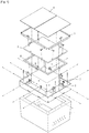
- FIG. 1 is a disassembled view of an underground laying type electric equipment container system according to an embodiment of the present invention.
- the underground laying type electric equipment container system includes a buried box 1, a box holder 2, a support 3, an upper cover 4, a lower cover 5, and a waterproof band 6, and an electric equipment box 7.
- an assembly process of elements described above and connection between the elements will be described with reference to the disassembled view illustrated in FIG. 1 .
- the buried box 1 is an outermost portion of the underground laying type electric equipment container system in lateral directions and a downward direction and is usually laid underground in the form of a manhole such that omni-directional lateral sides and an underside thereof are sealed and a portion of an upper surface thereof is opened.
- the lateral sides and the underside of the buried box 1 are laid underground and in order that the upper cover 4 thereof is horizontal to the surface of the earth, the upper surface of the buried box 1 is mounted downward from the ground surface by a lateral length of the box holder 2.
- the upper surface of the buried box 1 may be higher than the ground surface or parallel to the ground surface.
- the buried box 1 may preferably be formed of a material that is waterproof and highly durable, such as concrete, so that erosion of electric equipment therein due to moisture of underground, water, or microorganisms is prevented.
- the buried box 1 may also be formed of other materials than the above-described material.
- a compact process of broken stones may preferably be performed on a underground surface on which the buried box 1 is to be installed so that the buried box 1 is not sunk.
- the box holder 2 is formed of a quadrangular horizontal frame covering the upper surface of the buried box 1 and having the same shape as the upper surface of the buried box 1, an inner vertical frame that is orthogonally and upwardly bent from an inner edge of the horizontal frame, and an outer vertical frame that is orthogonally and upwardly bent from an outer edge of the horizontal frame.
- the horizontal frame of the box holder 2 has the same shape as the upper surface of the buried box 1 in order to cover the upper surface of the buried box 1, and thus, has a quadrangular opened portion corresponding to the opened upper surface of the buried box 1.
- the electric equipment box 7 is moved through this opened portion.
- the horizontal frame of the box holder 2 provides space for coupling with the lower cover 5, and the inner vertical frame provides an edge for tight coupling with the waterproof band 6 attached to the lower cover 5, and the outer vertical frame provides an edge for fixing the upper cover 4.
- nut-shaped grooves are formed in the upper surface of the buried box 1, and holes corresponding to the grooves of the buried box 1 are formed in the horizontal frame of the box holder 2.
- the buried box 1 and the box holder 2 may be coupled to each other as bolts are inserted into the grooves in the upper surface of the buried box 1 through the holes of the horizontal frame of the box holder 2.
- the horizontal frame of the box holder 2 may be coupled to the upper surface of the buried box 1 in an sealed state as a waterproof agent such as silicone is filled in a coupling portion between the buried box 1 and the box holder 2.
- the box holder 2 may be formed of a rigid material whose shape is not deformed under any condition.
- the box holder 2 may be formed of a metal plate.
- the support 3 is a shelf-shaped frame that supports the upper cover 4, and is attached to an inner portion of the outer vertical frame of the box holder 2 at a predetermined depth from the outer vertical frame. If the upper cover 4 is protruded from the ground, pedestrians may stumble over the upper cover 4 to fall down, and thus, the support 3 may preferably be attached to the inner portion of the outer vertical frame of the box holder 2 at a deeper depth that is greater than a height of the upper cover 4.
- the support 3 is formed of a quadrangular horizontal frame that contacts a lower surface of the upper cover 4 and a vertical frame that is orthogonally and downwardly bent from an outer edge of the horizontal frame.
- Holes for coupling with respect to the lower cover 5 are formed in the vertical frame of the box holder 2, and holes corresponding to the holes of the vertical frame of the box holder 2 are formed in the vertical frame of the support 3.
- the box holder 2 and the support 3 may be coupled to each other by passing through bolts through the holes of the vertical frame of the box holder 2 and the holes of the vertical frame of the support 3 and tightening nuts on the bolts.
- the upper cover 4 is mounted to the support 3 to cover the upper surface of the lower cover 5. As illustrated in FIG. 1 , the upper cover 4 is located at an outermost portion of the underground laying type electric equipment container system illustrated in FIG. 1 in an upward direction, and an upper surface of the upper cover 4 is exposed to the outside to function as a pavement.
- the upper cover 4 may be formed of, for example, a metal slab, a marble slab, a reinforced plastic slab, which is capable of enduring load of pedestrians or cars. Also, the upper cover 4 may be manufactured in the form of a box in which blocks used in pavement nearby may be mounted for harmonization with the pavement nearby.
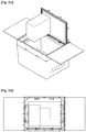
- FIG. 2 illustrates the underground laying type electric equipment container system while the upper cover 4 illustrated in FIG. 1 is closed.
- FIG. 2A is a perspective view of the underground laying type electric equipment container system while the upper cover 4 illustrated in FIG. 1 is closed.
- the upper cover 4 is formed of two slabs, but may also be formed of a single slab or of two or more slabs.
- a weight of the upper cover 4 may be increased.
- the upper cover 4 is to be liftable by a user, and thus, the upper cover 4 may be formed of several separate slabs according to the weight of the upper cover 4.
- FIG. 2B is a plan view of the underground laying type electric equipment container system while the upper cover 4 illustrated in FIG. 1 is closed.
- a larger quadrangle shown by a dotted line from among two quadrangles shown by a dotted line in FIG. 2B denotes the electric equipment box 7 in which the buried box 1 is embedded.
- a smaller quadrangle of the two quadrangles shown by a dotted line in FIG. 2B denotes a space for a dehumidifying agent provided on a lower surface in the buried box 1.
- the space of the dehumidifying agent is filled with a dehumidifying agent for eliminating moisture generated inside the buried box 1.
- a representative example of the dehumidifying agent may be silica gel.
- FIG. 2C is a front view of the underground laying type electric equipment container system while the upper cover 4 illustrated in FIG. 1 is closed.
- FIG. 2D is a side view of the underground laying type electric equipment container system while the upper cover 4 illustrated in FIG. 1 is closed.
- the upper cover 4 is an outermost portion of the underground laying type electric equipment container system according to the present embodiment in an upward direction and is located near the surface of the earth.
- the whole underground laying type electric equipment container system illustrated in FIG. 1 is laid underground such that the upper surface thereof is horizontal to the surface of the earth. If the underground laying type electric equipment container system illustrated in FIG. 1 is laid underground while it is either protruded from the surface of the earth or sunk underground, safety of pedestrians may be threatened by the underground laying type electric equipment container system.
- lower links of the box holder 2 and upper links of the lower cover 5 are connected to each other so that the box holder 2 and the lower cover 5 are coupled to each other, and as the waterproof band 6 and a circumference of the upper portion of the inner vertical frame of the box holder 2 are coupled to each other, a coupling portion between the box holder 2 and the lower cover 5 are sealed.
- the electric equipment box 7 that is moved as a single body with the lower cover 5 is located in the sealed inner space of the buried box 1 according to a position where the lower cover 5 covers the box holder 2.
- FIG. 3 illustrates the underground laying type electric equipment container system while the upper cover 4 illustrated in FIG. 1 is opened.
- FIG. 3A is a perspective view of the underground laying type electric equipment container system while the upper cover 4 illustrated in FIG. 1 is opened.
- FIG. 3B is a plan view of the underground laying type electric equipment container system while the upper cover 4 illustrated in FIG. 1 is opened.
- FIG. 3C is a front view of the underground laying type electric equipment container system while the upper cover 4 illustrated in FIG. 1 is opened.
- FIG. 3D is a side view of the underground laying type electric equipment container system while the upper cover 4 illustrated in FIG. 1 is opened.
- the lower cover 5 is exposed to the outside.
- the user may move the upper cover 4 out of the box holder 2 by lifting the upper cover 4 from the support 3.
- the upper cover 4 may be connected to the box holder 2 or the box via a chain or wire.
- a security device such as a lock may be inserted between the upper cover 4 and the box holder 2 or the buried box 1 so that only a user who has a right regarding the electric equipment box 7 may move the upper cover 4.
- the lower cover 5 seals a rectangular hole of the box holder 2 by covering the entire upper portion of the inner vertical frame of the box holder 2. As illustrated in FIG. 1 , outer lines of the rectangular hole of the box holder 2 is formed along the upper portion of the inner vertical frame, and thus, the lower cover 5 may cover the entire upper portion of the inner vertical frame of the box holder 2, thereby sealing the rectangular holes of the box holder 2.
- the waterproof band 6 that covers the entire upper portion of the inner vertical frame of the box holder 2 is attached to a lower surface of the lower cover 5, and coupling devices that allow adhesion between the upper portion of the inner vertical frame of the box holder 2 and the waterproof band 6 are installed on an upper surface of the horizontal frame of the box holder 2 and the lower cover 5.
- Some of the coupling devices that are temporarily coupled, from among the devices coupling the upper surface of the horizontal frame of the box holder 2 and the lower cover 5, may be coupled to each other or separated from each other by user's manipulation.
- the lower cover 5 is rotatable with respect to other coupling devices that are permanently coupled, as an axis of rotation, from among the coupling devices of the upper surface of the horizontal frame of the box holder 2 and the lower cover 5, by user's manipulation.
- the sealed inner space of the buried box 1 is formed as the waterproof band 6 is adhered to the upper portion of the upper surface of the horizontal frame of the box holder 2 by rotation of the lower cover 5 according to user's manipulation and the rectangular hole of the box holder 2 are sealed accordingly.
- sealing of the buried box 1 and movement of the electric equipment box 7 are conducted just by user's rotating the lower cover 5 with respect to the coupling devices fixed to the buried box 1, as an axis of rotation, and thus, most of the danger of accidents to the user and damages to the structures according to movement of the lower cover 5 is eliminated.
- Waterproof capability of the underground laying type electric equipment container system illustrated in FIG. 1 is determined based on a degree of adhesion between the upper portion of the inner vertical frame of the box holder 2 and the waterproof band 6. According to the conventional underground laying type electric equipment container system disclosed in Korean Patent No. 0947101 or Korean Utility Model No. 0443588 , waterproof capability of the underground laying type electric equipment container system is determined based on a force of a power unit such as a motor and thus coupling devices as those described above are not needed.
- the upper portion of the inner vertical frame of the box holder 2 and the waterproof band 6 are adhered to each other manually, and thus, coupling devices that allow adhesion between the upper portion of the inner vertical frame of the box holder 2 and the waterproof band 6 are needed.
- the electric equipment may be manually moved to the sealed inner space of the box.
- the coupling devices that allow adhesion between the upper portion of the inner vertical frame of the box holder 2 and the waterproof band 6 are installed on the upper surface of the horizontal frame of the box holder 2, and the coupling devices that allow adhesion between the upper portion of the inner vertical frame of the box holder 2 and the waterproof band are installed on the lower cover 5.
- Examples of the coupling device are links and hinges illustrated in FIG. 1 .
- Links are representative coupling devices that allow objects coupled by the links are coupled or separated by user's manipulation, and various types of links other than the links illustrated in FIG. 1 may be applied to the present embodiment.
- Hinges are representative coupling devices that allow objects coupled by the hinges are rotatable within up to a predetermined critical angle, and various types of hinges other than the hinges illustrated in FIG. 1 may be applied to the present embodiment.
- FIG. 1 six lower links and two lower hinges are attached to the upper surface of the horizontal frame of the box holder 2, and six upper links corresponding to the six lower links and two upper hinges corresponding to the two lower hinges are attached to the lower cover 5.
- the upper links and the upper hinges are attached to an upper surface of the lower cover 5, they may also be attached to the lower surface or a lateral surface of the lower cover 5.
- the horizontal frame of the box holder 2 and three lateral sides of the lower cover 5 may be respectively temporarily coupled to one another as the user temporarily connects the six upper links and the six lower links.
- the horizontal frame of the box holder 2 and the remaining one lateral side of the lower cover 5 may be permanently coupled to each other as the two lower hinges and the two upper hinges are permanently coupled to each other. While the six lower links and the six upper links attached to the horizontal frame of the box holder 2 and the three lateral sides of the lower cover 5 are separated, the lower cover 5 may be freely rotated with respect to the hinges, which are permanent coupling devices with respect to the box holder 2, as an axis of rotation, within up to a predetermined angle allowed by the hinges by user's manipulation.
- the lower cover 5 is coupled to all lateral sides of the horizontal frame of the box holder 2 and thus is not able to rotate.
- a gap that runs along a circumference of the lower surface of the lower cover 5 is formed in the lower surface of the lower cover 5 along the circumference of the upper portion of the inner vertical frame of the box holder 2, and the waterproof band 6 is inserted into the gap to be adhered.
- the waterproof band 6 may be formed of an elastic material such as rubber or silicone.
- the waterproof band 6 may be formed as a rubber packing.
- the waterproof band 6 attached to the lower surface of the lower cover 5 is pressed by the upper portion of the inner vertical frame of the box holder 2, and tight coupling between the inner vertical frame of the box holder 2 and the waterproof band 6 due to this pressing seals the gap between the inner vertical frame of the box holder 2 and the lower cover 5.
- the inner space of the buried box 1 is sealed from the outside.
- the coupling portion between the buried box 1 and the box holder 2 are permanently sealed by using a material such as a waterproof agent, but the coupling portions between the box holder 2 and the lower cover 5 are temporarily sealed by the tight coupling between the inner vertical frame of the box holder 2 and the waterproof band 6.
- waterproof capability of the underground laying type electric equipment container system illustrated in FIG. 1 is determined based on a degree of the adhesion between the upper portion of the inner vertical frame of the box holder 2 and the waterproof band 6.
- the degree of the adhesion between the upper portion of the inner vertical frame of the box holder 2 and the waterproof band 6 may also depend only on a human strength of the user who connects the upper links and the lower links. However, if the degree of adhesion by the human strength of the user is not sufficient, the adhesive force between the upper portion of the inner vertical frame of the box holder 2 and the waterproof band 6 may be increased, in addition to the human strength of the user, by the weight of the lower cover 5, the weight of the upper cover 4, and the weight of the electric equipment box 7.
- a gravitational force acting on the lower cover 5 may increase, and accordingly, a force of the waterproof band 6 attached to the lower cover 5, that presses the upper portion of the inner vertical frame of the box holder 2 also increases.
- the electric equipment box 7 is a box in which an electric equipment is embedded, and may be located in the sealed inner space of the buried box 1 that is formed as the upper portion of the inner vertical frame of the box holder 2 and the waterproof band 6 are adhered by user's manipulation or may be located outside the buried box 1.
- Examples of the electric equipment may include an outdoor transformer, an outdoor communication equipment, a streetlight panel board, or a traffic signal controller.
- the electric equipment box 7 may also be referred to as a panel board or a terminal board.
- the electric equipment box 7 may be located inside the buried box 1 that is laid underground, facilities related to electric equipment such as electric poles are no longer present on the ground, thereby improving the appearance of the city, allowing efficient use of city space, and providing safety because falling danger of the facilities is eliminated.
- the electric equipment box 7 is attached to the lower surface of the lower cover 5 that seals the inner space of the buried box 1. As described above, as the electric equipment box 7 is attached to the lower surface of the lower cover 5, the electric equipment box 7 may move with the lower cover 5 as a single body.
- the lower cover 5 is separated almost at a right angle with respect to the horizontal frame of the box holder 2 from the upper surface of the inner vertical frame of the box holder 2 by rotation of the lower cover 5 according to user's manipulation, and at the same time, the electric equipment box 7 may be moved out of the buried box 1 as a single body with the lower cover 5.
- the electric equipment box 7 located outside the buried box 1 may be moved into the sealed inner space of the buried box 1 as a single body with the lower cover 5 at the same time when the waterproof band 6 attached to the lower cover 6 is adhered to the upper surface of the inner vertical frame of the box holder 2 by rotation of the lower cover 5 according to user's manipulation.
- the electric equipment box 7 located in the sealed inner space of the buried box 1 may be moved out of the buried box 1 according to user's manipulation, maintenance and repair of the electric equipment is easy.
- An upper surface of the electric equipment box 7 is attached to an inner surface of the lower surface of the lower cover 5 that is surrounded by the waterproof band 6.
- Coupling devices that allow attachment of the electric equipment box 7 are installed on the upper surface of the electric equipment box 7 and the lower surface of the lower cover 5. From among the coupling devices on the upper surface of the electric equipment box 7 and the lower surface of the lower cover 5, some coupling devices that are temporarily coupled may be coupled to each other or separated from each other by user's manipulation. While some of the coupling devices are separated, the electric equipment box 7 is rotatable with respect to other coupling devices that are permanently coupled, as an axis of rotation, from among the coupling devices of the upper surface of the electric equipment box 7 and the lower surface of the lower cover 5, by user's manipulation.
- the coupling devices for coupling with respect to the electric equipment box 7 are installed on the lower surface of the lower cover 5, and coupling devices for coupling with respect to the lower cover 5 are installed on the upper surface of the electric equipment box 7.
- the coupling devices for coupling with respect to the lower cover 5 are installed on the upper surface of the electric equipment box 7.
- six upper links and two upper hinges may be attached to the lower surface of the lower cover 5.
- six lower links corresponding to the upper links and two lower hinges corresponding to the two upper hinges may be attached to the upper surface of the electric equipment box 7.
- the links and the hinges can be classified into upper ones and lower ones based on a state in which the electric equipment box 7 is located inside the sealed inner space of the buried box 1.
- rotating subjects are the lower cover 5 and the electric equipment box 7, and thus, the lower links and the lower hinges attached to the upper surface of the horizontal frame of the box holder 2 and the upper links and the upper hinges attached to the lower surface of the lower cover 5 are the same type, and the upper links and the upper hinges attached to the lower cover 5 and the lower links and the lower hinges attached to the upper surface of the electric equipment box 7 are the same type.
- the upper surface of the electric equipment box 7 and three lateral sides of the lower surface of the lower cover 5 may be temporarily coupled to one another as the user temporarily connects the six upper links and the six lower links.
- the upper surface of the electric equipment box 7 and the remaining one lateral side of the lower cover 5 may be permanently coupled to each other as the two lower hinges and the two upper hinges are permanently coupled to each other. While the six lower links and the six upper links attached to the upper surface of the electric equipment box 7 and the three lateral sides of the lower surface of the lower cover 5 are separated, the electric equipment box 7 may be freely rotated with respect to the hinges, which are permanent coupling devices with respect to the box holder 2, as an axis of rotation, within up to a predetermined angle allowed by the hinges by user's manipulation.
- the upper surface of the electric equipment box 7 is coupled to all lateral sides of the lower surface of the lower cover 5 and thus is not able to rotate.
- a plurality of holes through which a plurality of cables connecting the electric equipment in the electric equipment box 7 and the electric equipment outside the buried box 1 may be laid, may be formed in a portion of the lateral side of the buried box 1.
- a cable is passed through one of the holes and then a gap between the hole and the cable is filled with a waterproof agent, thereby sealing the gap between the hole and the cable.
- some of the holes that are not used in laying of the cable may be completely filled with a waterproof agent to be sealed.
- the cable that is laid as above has a length that is enough not to disturb vertical movement of the electric equipment box 7 inside the buried box 1.
- a wired cable as above is not necessarily to be laid in the buried box 1.
- the electric equipment outside the buried box 1 may be an electric equipment of a power plant or an electric equipment in another buried box besides the buried box 1.
- a cable that protects other electric equipment such as a ground cable may be laid in the buried box 1.
- the electric equipment of the electric equipment box 7 is an outdoor transformer
- a high-voltage current flows through electric elements such as wires, coils, or terminals that constitute the electric equipment.
- electric elements such as wires, coils, or terminals that constitute the electric equipment.
- a high voltage is temporarily applied to the electric elements of the electric equipment
- an insulated state of the air in the buried box 1 is collapsed.
- discharge in the air is generated with sparks in the buried box 1. Due to expansion of the air due to the sparks or expansion of the air due to heat of a chemical reaction during the discharge in the air, a pressure in the buried box 1 is gradually increased.
- a decompression device that reduces an internal pressure of the buried box 1, for example, a safety valve, may be additionally inserted into the lower cover 5.
- FIG. 4 illustrates the underground laying type electric equipment container system while the lower cover 5 illustrated in FIG. 1 is opened.
- FIG.4A is a perspective view of the underground laying type electric equipment container system while the lower cover 5 illustrated in FIG. 1 is opened.
- FIG. 4B is a plan view of the underground laying type electric equipment container system while the lower cover 5 illustrated in FIG. 1 is opened.
- FIG. 4C is a front view of the underground laying type electric equipment container system while the lower cover 5 illustrated in FIG. 1 is opened.
- FIG. 4D is a side view of the underground laying type electric equipment container system while the lower cover 5 illustrated in FIG. 1 is opened. As illustrated in FIG.
- the electric equipment box 7 rotates as a single body with the lower cover 5 to be moved out of the buried box 1.
- a gravitational force acting on the lower cover 5 is directed in an opposite direction from a direction in which the lower cover 5 is closed, and a portion of the upper surface of the lower cover 5 contacts the upper portion of the outer vertical frame of the box holder 2 so as to fix the lower cover 5.
- the box holder 2 and the lower cover 5 are separated from each other, and the lower cover 5 is finally separated from the box holder 2 almost at a right angle with respect to the box holder 2.
- the electric equipment box 7 is located outside the buried box 1 corresponding to the position of the lower cover 5 at which the lower cover 5 is at a right angle with respect to the box holder 2. In this state, the user may easily access the electric equipment box 7. In order to allow the user to access the electric equipment box 7 even more safely, a unit that fixes the position of the lower cover 5 may be used.
- movement of the lower cover 5 as described above is based on rotation of the lower cover 5 with respect to the hinges that connect the lower cover 5 and the box holder 2.
- the present embodiment relates to a manual system in which rotation of the lower cover 5 is conducted by a human strength of a user. If the weight of an electric equipment is considerably high, the lower cover 5 may not be moved by a human strength of the user or an accident that the lower cover 5 is suddenly closed due to negligence of the user may occur. To compensate for such problems, an assistant device that increases a human strength of the user acting on the lower cover 5 to rotate the lower cover 5 may be installed between the lower cover 5 and the box holder 2.
- FIG. 5 illustrates the underground laying type electric equipment container system while the electric equipment box 7 illustrated in FIG. 1 is moved.
- FIG. 5A is a perspective view of the underground laying type electric equipment container system while the electric equipment box 7 illustrated in FIG. 1 is moved.
- FIG. 5B is a plan view of the underground laying type electric equipment container system while the electric equipment box 7 illustrated in FIG. 1 is moved.
- FIG. 5C is a front view of the underground laying type electric equipment container system while the electric equipment box 7 illustrated in FIG. 1 is moved.
- FIG. 5D is a side view of the underground laying type electric equipment container system while the electric equipment box 7 illustrated in FIG. 1 is moved.
- the box holder 2 and the lower cover 5 are separated from each other, and the lower cover 5 is finally separated from the box holder 2 almost at a right angle with respect to the box holder 2.
- the upper surface of the electric equipment box 7 is exposed to the outside.
- a user interface panel of the electric equipment is disposed in an inner portion at the upper surface of the electric equipment box 7, and thus, the user may access the user interface panel of the electric equipment by opening the upper surface of the electric equipment box 7.
- a unit that fixes a position of the electric equipment box 7 may be used.
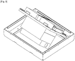
- FIG. 6 illustrates an electric equipment being embedded in the electric equipment box 7 illustrated in FIG. 1 .
- the electric equipment is formed of two substrates on which multiple components are installed.
- two boards 71 and 72 are installed in the electric equipment box 7.
- the substrate installed on the board 71 is exposed to the outside and thus is not difficult for the user to manipulate the same.
- the substrate installed on the board 72 is covered by the board 71, and thus, to manipulate the substrate installed on the board 72, the board 71 is to be moved.
- the board 71 and the electric equipment box 7 are connected to each other by hinges so that the board 71 may be freely rotated with respect to a coupling portion with the electric equipment box 7 as an axis of rotation, by using the hinges. Also, in order to allow the board 71 to rotate at a right angle, no component may be installed in a portion of the substrate that overlaps with the electric equipment box 7 according to the right-angled rotation of the board 71.
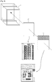
- FIG. 7 illustrates examples of components of the electric equipment embedded in the electric equipment box 7 illustrated in FIG. 1 .
- a representative example of electric equipment embedded in the electric equipment box 7 is a circuit breaker.
- an over-current trip device is illustrated as a representative example of components that constitute the circuit breaker. If a current flowing through a coil illustrated in FIG. 7 exceeds a rated current, a plunger is pulled to be moved towards a first armature, and then a second armature is pulled to automatically block the circuit breaker. If an even higher current flows, a magnetic flux of a magnetic circuit increases, and thus the second armature is pulled even though the plunger does not move, thereby automatically blocking the circuit breaker. However, due to a gravitational force acting on the plunger, an operational current whereby the circuit breaker is blocked may be changed due to an attachment angle of the circuit breaker.
- an electric equipment that includes at least one component whose performance changes according to various directions of Earth's gravitational force may be embedded in the electric equipment box 7.
- a direction of the user interface panel of the electric equipment has to be opposite direction to Earth's gravitational force.
- the direction of the user interface panel of the electric equipment has to be towards the upper surface of the electric equipment box 7, and the user interface panel of the electric equipment is opened to the outside through the upper surface of the electric equipment box 7.
- the upper surface of the electric equipment box 7 located inside the sealed inner space of the buried box 1 contacts the lower surface of the lower cover 5, and the electric equipment box 7 is moved with the lower cover 5 as a single body and is exposed to the outside. Accordingly, the upper surface of the electric equipment box 7 is covered by the lower surface of the lower cover 5 and thus the user is not able to access the upper surface.
- the upper surface of the electric equipment box 7 may be temporarily attached to the lower surface of the lower cover 5 so that the user may access the user interface panel of the electric equipment by opening the upper surface of the electric equipment box 7 that is temporarily attached to the lower surface of the lower cover 5.
- some of the coupling devices of the upper surface of the electric equipment box 7 and the lower surface of the lower cover 5 that are temporarily coupled may be coupled to each other or separated from each other by user's manipulation, and while some of the coupling devices are separated, the electric equipment box 7 may be rotatable with respect to other coupling devices that are permanently coupled, as an axis of rotation, from among the coupling devices of the upper surface of the electric equipment box 7 and the lower surface of the lower cover 5, by user's manipulation.
- the user may access the user interface panel of the electric equipment even when an opening surface of the user interface panel of the electric equipment is covered by the lower surface of the lower cover 5 due to the installation direction of the electric equipment embedded in the electric equipment box 7.
- the upper surface of the electric equipment box 7 is opened at the same time. That is, as the lower links of the electric equipment box 7 and the upper links of the lower cover 5 are separated from each other, the upper surface of the electric equipment box 7 is separated from the lower surface of the lower cover 5 almost at a right angle with respect to the lower cover 5, and at the same time, the upper surface of the electric equipment box 7 is completely exposed to the outside.
- the upper surface of the electric equipment box 7 that is separated from the lower surface of the lower cover 5 almost at a right angle is adhered to the lower surface of the lower cover 5 by rotation of the lower cover 5 according to user's manipulation, and at the same time, the upper surface of the electric equipment box 7 is covered by the lower surface of the lower cover 5.
- FIG. 8 is a detailed perspective view of the underground laying type electric equipment container system while the lower cover 5 illustrated in FIG. 1 is closed. As illustrated in FIG. 8 , a container of various equipments such as equipments needed to operate the electric equipment embedded in the electric equipment box 7 may be loaded on the lower cover 5.
- FIG. 9 is a detailed perspective view of the underground laying type electric equipment container system in which about a half of the lower cover 5 illustrated in FIG. 1 is opened.
- FIG. 10 is a detailed perspective view of the underground laying type electric equipment container system while the lower cover 5 illustrated in FIG. 1 is completely opened.
- FIG. 11 is a detailed perspective view of the underground laying type electric equipment container system in which the electric equipment box 7 illustrated in FIG. 1 is rotated by about a half turn.
- FIG. 9 is a detailed perspective view of the underground laying type electric equipment container system in which the electric equipment box 7 illustrated in FIG. 1 is rotated by about a half turn.
- FIG. 9 is a detailed perspective view of the underground laying type electric equipment container system
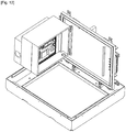
- FIG. 12 is a detailed perspective view of the underground laying type electric equipment container system in which the electric equipment box 7 illustrated in FIG. 1 is completely rotated.
- FIGS. 8 through 12 illustrate in a slide show manner how the electric equipment box 7 located in the sealed space of the buried box 1 is moved to the ground and opened according to the above-described characteristics.
- FIGS. 13 through 16 illustrate a modified example of the underground laying type electric equipment container system illustrated in FIG. 1 .
- FIG. 13 is a perspective view of the modified example of the underground laying type electric equipment container system illustrated in FIG. 1 .
- FIG. 14 is a plan view of the modified example of the underground laying type electric equipment container system illustrated in FIG. 1 .
- FIG. 15 is a front view of the modified example of the underground laying type electric equipment container system illustrated in FIG. 1 .
- FIG. 16 is a side view of the modified example of the underground laying type electric equipment container system illustrated in FIG. 1 .
- the weight of the lower cover 5 may be increased, and if the weight of the electric equipment is considerably high, it may be impossible to move the lower cover 5 by a human strength of the user. Due to the weight of the lower cover 5 and the electric equipment, it may be difficult to lift and rotate the lower cover 5 just by a human strength of the user. In addition, if a human strength of the user needed to lift and rotate the lower cover 5 is reduced, not only the burden for the user in regard to movement of the lower cover 5 and the electric equipment box 7 may be reduced but damages due to collision between the lower cover 5 and box holder 2 due to user's mistake may also be eliminated.
- an assistant device may be installed between the box holder 2 and the lower cover 5 to increase a human strength of the user that acts on the lower cover 5 to rotate the lower cover 5.
- a gas spring for example, a gas spring, a gear, or a pulley may be used.
- a gas spring is used as an assistant device that is installed between the box holder 2 and the lower cover 5.
- the gas spring as described above is typically used in a hood or a trunk of an automobile.
- the gas spring is a type of a spring that uses a compressed gas, and a high-pressure gas spring contains a large amount of energy, and this energy is used in increasing the human strength of the user.
- a manual underground laying type electric equipment container system provides an underground laying type electric equipment container system having a structure in which inner space of the buried box 1 that is laid underground is sealed just by a human strength of the user without a power unit and the electric equipment box 7 may be moved to the sealed inner space of the buried box 1 at the same time.
- the electric equipment which has been on the ground may be manually moved into the sealed inner space of the buried box 1 that is laid underground, facilities related to the electric equipment such as electric poles may be removed from the ground, and accordingly, the appearance of the city is improved, city space may be efficiently used, and safety is ensured because the danger of falling facilities is not present.
- the electric equipment box 7 located in the sealed inner space of the buried box 1 may be moved out of the buried box 1 according to user's manipulation, and thus, maintenance and repair of the electric equipment is easy.
- the manual underground laying type electric container system As the manual underground laying type electric container system is provided as described above, multiple devices such as a power unit and a controller of the power unit which are needed in the conventional automatic underground laying type electric equipment container system are no longer needed, and accordingly, the manufacturing costs and size of the underground laying type electric equipment container system may be significantly reduced.
- sealing of the buried box 1 and movement of the electric equipment box 7 are conducted just by user's rotating the lower cover 5 with respect to the coupling devices fixed to the buried box 1, as an axis of rotation, and thus, most of the danger of accidents to the user and damages to the structures according to movement of the lower cover 5 is eliminated.
- the electric equipment box 7 is attached to the lower surface of the lower cover 5 that seals the inner space of the buried box 1 and thus may be moved out of or into the box as a single body with the lower cover 5, the manufacturing costs and the size of the underground laying type electric equipment container system may be minimized.
- the user is able to rotate the electric equipment box 7 with respect to the coupling device that is fixed to the lower cover 5, as an axis of rotation, the user may access the user interface panel of the electric equipment even when an opening surface of the user interface panel of the electric equipment is covered by the lower surface of the lower cover 5 due to the installation direction of the electric equipment embedded in the electric equipment box 7.
- an assistant device is installed between the box holder 2 and the lower cover 5 to increase a human strength of the user that acts on the lower cover 5 to rotate the lower cover 5, and accordingly, not only the burden for the user in regard to movement of the lower cover 5 and the electric equipment box 7 may be reduced but damages due to collision between the lower cover 5 and box holder 2 due to user's mistake may also be eliminated.
Landscapes
- Engineering & Computer Science (AREA)
- Power Engineering (AREA)
- Microelectronics & Electronic Packaging (AREA)
- Architecture (AREA)
- Civil Engineering (AREA)
- Structural Engineering (AREA)
- Casings For Electric Apparatus (AREA)
- Patch Boards (AREA)
Description
- The present invention relates to a container system in which at least one electric equipment may be embedded, and more particularly, to an electric equipment container system which may be manually laid underground.
- According to the conventional art, electric equipment such as an outdoor transformer, an outdoor communication equipment, or a streetlight panel board are installed at an upper portion of a large-sized ground facility such as an electric pole, and thus a person who manages the electric equipment has to go up the electric pole for maintenance and repair of the electric equipment, and this maintenance and repair of the electric equipment is complicated and dangerous. Also, according to the rapid industrialization of the modern society, the demand of electric equipment has exploded so that many facilities related to electric equipment, such as electric poles, have been introduced in many places in the city. As a result, the facilities related to electric equipment have been factors that ruin the appearance of the city and hinder the efficient use of city space, and threaten safety of citizens.
- Korean Patent No.
0947101 0443588 -
EP 0 620 624 A1 - The present invention provides an underground laying type electric equipment container system having a structure in which inner space of a buried box which is laid underground may be sealed by using just a human strength of a user and an electric equipment box may be moved into the sealed inner space of the buried box at the same time. The technical objective to be achieved by the present embodiment is not limited to the technical objectives described above, and there may be also other technical objectives.
- According to an aspect of the present invention, there is provided an underground laid electric equipment container system, including: a buried box that is laid underground in the form of a manhole such that omni-directional lateral sides and an underside of the buried box are sealed and a portion of an upper surface of the buried box is opened; a box holder that includes a horizontal frame that is coupled to the upper surface of the buried box in an sealed state and an inner vertical frame that is upwardly bent from an inner edge of the horizontal frame; a cover, to which a waterproof band covering the entire upper portion of the inner vertical frame is attached, wherein coupling devices with an upper surface of the horizontal fame that allow adhesion between the upper portion of the inner vertical frame and the waterproof band are installed on the cover; and an electric equipment box that is disposed in sealed inner space of the buried box that is formed as the upper portion of the inner vertical frame and the waterproof band are adhered to each other by user's manipulation.
- Some of the coupling devices of the upper surface of the horizontal frame and the cover are coupled or separated by user's manipulation, and while some of the coupling devices are separated, the cover is rotatable with respect to other coupling devices, as an axis of rotation, from among the coupling devices, by user's manipulation. The sealed inner space of the buried box is formed as the waterproof band is adhered to an upper portion of the horizontal frame by rotation of the cover according to user's manipulation.
- The electric equipment box is attached to a lower surface of the cover and moved as a single body with the cover. Some of the coupling devices of the upper surface of the horizontal frame and the cover are coupled or separated by user's manipulation, and while some of the coupling devices are separated, the cover is rotatable with respect to other coupling devices from among the coupling devices, as an axis of rotation, by user's manipulation, and the electric equipment box may be moved out of the buried box as the cover is separated from the upper surface of the inner vertical frame of the box holder by rotation of the cover according to user's manipulation, and at the same time, the electric equipment box can rotate as a single body with the cover.
- An assistant device may be installed between the box holder and the cover to increase a human strength of the user that acts on the cover to rotate the cover. The assistant device may be a gas spring. The box holder may further include an outer vertical frame that is upwardly bent from an outer edge of the horizontal frame, and the underground laying type electric equipment container system may further include: a support that is attached to an inner portion of the outer vertical frame at a predetermined depth from an upper portion of the outer vertical frame; and an upper cover that is mounted to the support.
- An underground laying type electric equipment container system having a structure in which inner space of a buried box which is laid underground may be sealed by using just a human strength of a user and an electric equipment box may be moved into the sealed inner space of the buried box at the same time, thereby providing a manual underground laying type electric equipment container system. As the electric equipment which has been on the ground may be manually moved into the sealed inner space of the buried box that is laid underground, facilities related to the electric equipment such as electric poles may be removed from the ground, and accordingly, the appearance of the city is improved, city space may be efficiently used, and safety is ensured as the danger of conduction of the facilities is not present. Since the manual underground laying type electric container system is provided, multiple devices such as a power unit and a controller of the power unit which are needed in the conventional automatic underground laying type electric equipment container system are no longer needed, and thus, the manufacturing costs and size of the underground laying type electric equipment container system may be significantly reduced.
-
-
FIG. 1 is a disassembled view of an underground laying type electric equipment container system according to an embodiment of the present invention; -
FIG. 2 illustrates an underground laying type electric equipment container system while anupper cover 4 illustrated inFIG. 1 is closed; -
FIG. 3 illustrates an underground laying type electric equipment container system while theupper cover 4 illustrated inFIG. 1 is opened; -
FIG. 4 illustrates an underground laying type electric equipment container system while alower cover 5 illustrated inFIG. 1 is opened; -
FIG. 5 illustrates an underground laying type electric equipment container system while anelectric equipment box 7 illustrated inFIG. 1 is moved; -
FIG. 6 illustrates an electric equipment being embedded in theelectric equipment box 7 illustrated inFIG. 1 ; -
FIG. 7 illustrates examples of components of an electric equipment embedded in theelectric equipment box 7 illustrated inFIG. 1 ; -
FIG. 8 is a detailed perspective view of the underground laying type electric equipment container system in which thelower cover 5 illustrated inFIG. 1 is closed; -
FIG. 9 is a detailed perspective view of the underground laying type electric equipment container system in which about a half of thelower cover 5 illustrated inFIG. 1 is opened; -
FIG. 10 is a detailed perspective view of the underground laying type electric equipment container system in which thelower cover 5 illustrated inFIG. 1 is completely opened; -
FIG. 11 is a detailed perspective view of the underground laying type electric equipment container system in which theelectric equipment box 7 illustrated inFIG. 1 is rotated by about a half turn; -
FIG. 12 is a detailed perspective view of the underground laying type electric equipment container system in which theelectric equipment box 7 illustrated inFIG. 1 is completely rotated; -
FIG. 13 is a perspective view of a modified example of the underground laying type electric equipment container system illustrated inFIG. 1 ; -
FIG. 14 is a plan view of the modified example of the underground laying type electric equipment container system illustrated inFIG. 1 ; -
FIG. 15 is a front view of the modified example of the underground laying type electric equipment container system illustrated inFIG. 1 ; and -
FIG. 16 is a side view of the modified example of the underground laying type electric equipment container system illustrated inFIG. 1 . - Hereinafter, embodiments of the present invention will be described in detail with reference to the drawings. If water penetrates into an electric equipment such as an outdoor transformer, an outdoor communication equipment, a streetlight panel board, or a traffic light controller, the electric equipment may get out of order due to, for example, electric leakage. A unit for preventing penetration of rain water or the like, for example, an umbrella-shaped dome, is covered over the electric equipment that is installed outdoor. The embodiments of the present invention are characterized by a system whereby an electric equipment may be manually laid underground while preventing penetration of rain water etc. into the electric equipment. Thus, detailed description of structure and operation of the electric equipment that are well-known in the art will be omitted.
-
FIG. 1 is a disassembled view of an underground laying type electric equipment container system according to an embodiment of the present invention. Referring toFIG. 1 , the underground laying type electric equipment container system includes a buriedbox 1, abox holder 2, asupport 3, anupper cover 4, alower cover 5, and awaterproof band 6, and anelectric equipment box 7. Hereinafter, an assembly process of elements described above and connection between the elements will be described with reference to the disassembled view illustrated inFIG. 1 . - The buried
box 1 is an outermost portion of the underground laying type electric equipment container system in lateral directions and a downward direction and is usually laid underground in the form of a manhole such that omni-directional lateral sides and an underside thereof are sealed and a portion of an upper surface thereof is opened. the lateral sides and the underside of the buriedbox 1 are laid underground and in order that theupper cover 4 thereof is horizontal to the surface of the earth, the upper surface of the buriedbox 1 is mounted downward from the ground surface by a lateral length of thebox holder 2. However, according to an installation environment of the buriedbox 1 or the intention of a person who installs, the upper surface of the buriedbox 1 may be higher than the ground surface or parallel to the ground surface. In particular, the buriedbox 1 may preferably be formed of a material that is waterproof and highly durable, such as concrete, so that erosion of electric equipment therein due to moisture of underground, water, or microorganisms is prevented. However, it will be obvious to one of ordinary skill in the art that the buriedbox 1 may also be formed of other materials than the above-described material. In addition, when laying the buriedbox 1 underground, a compact process of broken stones may preferably be performed on a underground surface on which the buriedbox 1 is to be installed so that the buriedbox 1 is not sunk. - The
box holder 2 is formed of a quadrangular horizontal frame covering the upper surface of the buriedbox 1 and having the same shape as the upper surface of the buriedbox 1, an inner vertical frame that is orthogonally and upwardly bent from an inner edge of the horizontal frame, and an outer vertical frame that is orthogonally and upwardly bent from an outer edge of the horizontal frame. The horizontal frame of thebox holder 2 has the same shape as the upper surface of the buriedbox 1 in order to cover the upper surface of the buriedbox 1, and thus, has a quadrangular opened portion corresponding to the opened upper surface of the buriedbox 1. Theelectric equipment box 7 is moved through this opened portion. The horizontal frame of thebox holder 2 provides space for coupling with thelower cover 5, and the inner vertical frame provides an edge for tight coupling with thewaterproof band 6 attached to thelower cover 5, and the outer vertical frame provides an edge for fixing theupper cover 4. - As illustrated in
FIG. 1 , nut-shaped grooves are formed in the upper surface of the buriedbox 1, and holes corresponding to the grooves of the buriedbox 1 are formed in the horizontal frame of thebox holder 2. The buriedbox 1 and thebox holder 2 may be coupled to each other as bolts are inserted into the grooves in the upper surface of the buriedbox 1 through the holes of the horizontal frame of thebox holder 2. The horizontal frame of thebox holder 2 may be coupled to the upper surface of the buriedbox 1 in an sealed state as a waterproof agent such as silicone is filled in a coupling portion between the buriedbox 1 and thebox holder 2. Thebox holder 2 may be formed of a rigid material whose shape is not deformed under any condition. For example, thebox holder 2 may be formed of a metal plate. - The
support 3 is a shelf-shaped frame that supports theupper cover 4, and is attached to an inner portion of the outer vertical frame of thebox holder 2 at a predetermined depth from the outer vertical frame. If theupper cover 4 is protruded from the ground, pedestrians may stumble over theupper cover 4 to fall down, and thus, thesupport 3 may preferably be attached to the inner portion of the outer vertical frame of thebox holder 2 at a deeper depth that is greater than a height of theupper cover 4. Thesupport 3 is formed of a quadrangular horizontal frame that contacts a lower surface of theupper cover 4 and a vertical frame that is orthogonally and downwardly bent from an outer edge of the horizontal frame. Holes for coupling with respect to thelower cover 5 are formed in the vertical frame of thebox holder 2, and holes corresponding to the holes of the vertical frame of thebox holder 2 are formed in the vertical frame of thesupport 3. Thebox holder 2 and thesupport 3 may be coupled to each other by passing through bolts through the holes of the vertical frame of thebox holder 2 and the holes of the vertical frame of thesupport 3 and tightening nuts on the bolts. - The
upper cover 4 is mounted to thesupport 3 to cover the upper surface of thelower cover 5. As illustrated inFIG. 1 , theupper cover 4 is located at an outermost portion of the underground laying type electric equipment container system illustrated inFIG. 1 in an upward direction, and an upper surface of theupper cover 4 is exposed to the outside to function as a pavement. Theupper cover 4 may be formed of, for example, a metal slab, a marble slab, a reinforced plastic slab, which is capable of enduring load of pedestrians or cars. Also, theupper cover 4 may be manufactured in the form of a box in which blocks used in pavement nearby may be mounted for harmonization with the pavement nearby. -
FIG. 2 illustrates the underground laying type electric equipment container system while theupper cover 4 illustrated inFIG. 1 is closed.FIG. 2A is a perspective view of the underground laying type electric equipment container system while theupper cover 4 illustrated inFIG. 1 is closed. As illustrated inFIG. 2A , theupper cover 4 is formed of two slabs, but may also be formed of a single slab or of two or more slabs. As will be described below, in order to reinforce an adhesive force between an upper portion of the vertical frame of thebox holder 2 and thewaterproof band 6, a weight of theupper cover 4 may be increased. Theupper cover 4 is to be liftable by a user, and thus, theupper cover 4 may be formed of several separate slabs according to the weight of theupper cover 4. -
FIG. 2B is a plan view of the underground laying type electric equipment container system while theupper cover 4 illustrated inFIG. 1 is closed. A larger quadrangle shown by a dotted line from among two quadrangles shown by a dotted line inFIG. 2B denotes theelectric equipment box 7 in which the buriedbox 1 is embedded. A smaller quadrangle of the two quadrangles shown by a dotted line inFIG. 2B denotes a space for a dehumidifying agent provided on a lower surface in the buriedbox 1. The space of the dehumidifying agent is filled with a dehumidifying agent for eliminating moisture generated inside the buriedbox 1. A representative example of the dehumidifying agent may be silica gel. -
FIG. 2C is a front view of the underground laying type electric equipment container system while theupper cover 4 illustrated inFIG. 1 is closed.FIG. 2D is a side view of the underground laying type electric equipment container system while theupper cover 4 illustrated inFIG. 1 is closed. As illustrated inFIGS. 2C and 2D , theupper cover 4 is an outermost portion of the underground laying type electric equipment container system according to the present embodiment in an upward direction and is located near the surface of the earth. As described above, the whole underground laying type electric equipment container system illustrated inFIG. 1 is laid underground such that the upper surface thereof is horizontal to the surface of the earth. If the underground laying type electric equipment container system illustrated inFIG. 1 is laid underground while it is either protruded from the surface of the earth or sunk underground, safety of pedestrians may be threatened by the underground laying type electric equipment container system. - As illustrated in
FIGS. 2C and 2D , lower links of thebox holder 2 and upper links of thelower cover 5 are connected to each other so that thebox holder 2 and thelower cover 5 are coupled to each other, and as thewaterproof band 6 and a circumference of the upper portion of the inner vertical frame of thebox holder 2 are coupled to each other, a coupling portion between thebox holder 2 and thelower cover 5 are sealed. Theelectric equipment box 7 that is moved as a single body with thelower cover 5 is located in the sealed inner space of the buriedbox 1 according to a position where thelower cover 5 covers thebox holder 2. -
FIG. 3 illustrates the underground laying type electric equipment container system while theupper cover 4 illustrated inFIG. 1 is opened.FIG. 3A is a perspective view of the underground laying type electric equipment container system while theupper cover 4 illustrated inFIG. 1 is opened.FIG. 3B is a plan view of the underground laying type electric equipment container system while theupper cover 4 illustrated inFIG. 1 is opened.FIG. 3C is a front view of the underground laying type electric equipment container system while theupper cover 4 illustrated inFIG. 1 is opened.FIG. 3D is a side view of the underground laying type electric equipment container system while theupper cover 4 illustrated inFIG. 1 is opened. - As illustrated in
FIG. 3 , as two slabs which form theupper cover 4 are moved out of thebox holder 2, thelower cover 5 is exposed to the outside. For example, the user may move theupper cover 4 out of thebox holder 2 by lifting theupper cover 4 from thesupport 3. To prevent loss of theupper cover 4, theupper cover 4 may be connected to thebox holder 2 or the box via a chain or wire. Alternatively, a security device such as a lock may be inserted between theupper cover 4 and thebox holder 2 or the buriedbox 1 so that only a user who has a right regarding theelectric equipment box 7 may move theupper cover 4. - The
lower cover 5 seals a rectangular hole of thebox holder 2 by covering the entire upper portion of the inner vertical frame of thebox holder 2. As illustrated inFIG. 1 , outer lines of the rectangular hole of thebox holder 2 is formed along the upper portion of the inner vertical frame, and thus, thelower cover 5 may cover the entire upper portion of the inner vertical frame of thebox holder 2, thereby sealing the rectangular holes of thebox holder 2. To seal the rectangular hole of thebox holder 2, thewaterproof band 6 that covers the entire upper portion of the inner vertical frame of thebox holder 2 is attached to a lower surface of thelower cover 5, and coupling devices that allow adhesion between the upper portion of the inner vertical frame of thebox holder 2 and thewaterproof band 6 are installed on an upper surface of the horizontal frame of thebox holder 2 and thelower cover 5. Some of the coupling devices that are temporarily coupled, from among the devices coupling the upper surface of the horizontal frame of thebox holder 2 and thelower cover 5, may be coupled to each other or separated from each other by user's manipulation. - While some of the coupling devices are separated, the
lower cover 5 is rotatable with respect to other coupling devices that are permanently coupled, as an axis of rotation, from among the coupling devices of the upper surface of the horizontal frame of thebox holder 2 and thelower cover 5, by user's manipulation. The sealed inner space of the buriedbox 1 is formed as thewaterproof band 6 is adhered to the upper portion of the upper surface of the horizontal frame of thebox holder 2 by rotation of thelower cover 5 according to user's manipulation and the rectangular hole of thebox holder 2 are sealed accordingly. When the user moves thelower cover 5 in an arbitrary direction or to an arbitrary position, the possibility of a danger to a user or damages to structures such as thebox holder 2 and thelower cover 5 according to movement of thelower cover 5 is high. According to the present embodiment, sealing of the buriedbox 1 and movement of theelectric equipment box 7 are conducted just by user's rotating thelower cover 5 with respect to the coupling devices fixed to the buriedbox 1, as an axis of rotation, and thus, most of the danger of accidents to the user and damages to the structures according to movement of thelower cover 5 is eliminated. - As the rectangular hole of the
box holder 2 is sealed, inner space of the buriedbox 1 in which theelectric equipment box 7 is located is sealed. Consequently, rain water or the like is not able to penetrate into the electric equipment embedded in theelectric equipment box 7. Waterproof capability of the underground laying type electric equipment container system illustrated inFIG. 1 is determined based on a degree of adhesion between the upper portion of the inner vertical frame of thebox holder 2 and thewaterproof band 6. According to the conventional underground laying type electric equipment container system disclosed in Korean Patent No.0947101 0443588 FIG. 1 , the upper portion of the inner vertical frame of thebox holder 2 and thewaterproof band 6 are adhered to each other manually, and thus, coupling devices that allow adhesion between the upper portion of the inner vertical frame of thebox holder 2 and thewaterproof band 6 are needed. As described above, as thebox holder 2 of the buriedbox 1 and thelower cover 5 seal inner space of a box, which is laid underground, by user's manipulation, the electric equipment may be manually moved to the sealed inner space of the box. - As described above, the coupling devices that allow adhesion between the upper portion of the inner vertical frame of the
box holder 2 and thewaterproof band 6 are installed on the upper surface of the horizontal frame of thebox holder 2, and the coupling devices that allow adhesion between the upper portion of the inner vertical frame of thebox holder 2 and the waterproof band are installed on thelower cover 5. Examples of the coupling device are links and hinges illustrated inFIG. 1 . Links are representative coupling devices that allow objects coupled by the links are coupled or separated by user's manipulation, and various types of links other than the links illustrated inFIG. 1 may be applied to the present embodiment. Hinges are representative coupling devices that allow objects coupled by the hinges are rotatable within up to a predetermined critical angle, and various types of hinges other than the hinges illustrated inFIG. 1 may be applied to the present embodiment. - As illustrated in
FIG. 1 , six lower links and two lower hinges are attached to the upper surface of the horizontal frame of thebox holder 2, and six upper links corresponding to the six lower links and two upper hinges corresponding to the two lower hinges are attached to thelower cover 5. Referring toFIG. 1 , although the upper links and the upper hinges are attached to an upper surface of thelower cover 5, they may also be attached to the lower surface or a lateral surface of thelower cover 5. The horizontal frame of thebox holder 2 and three lateral sides of thelower cover 5 may be respectively temporarily coupled to one another as the user temporarily connects the six upper links and the six lower links. The horizontal frame of thebox holder 2 and the remaining one lateral side of thelower cover 5 may be permanently coupled to each other as the two lower hinges and the two upper hinges are permanently coupled to each other. While the six lower links and the six upper links attached to the horizontal frame of thebox holder 2 and the three lateral sides of thelower cover 5 are separated, thelower cover 5 may be freely rotated with respect to the hinges, which are permanent coupling devices with respect to thebox holder 2, as an axis of rotation, within up to a predetermined angle allowed by the hinges by user's manipulation. While the six lower links and the six upper links attached to the horizontal frame of thebox holder 2 and the three lateral sides of thelower cover 5 are connected to each other, thelower cover 5 is coupled to all lateral sides of the horizontal frame of thebox holder 2 and thus is not able to rotate. - A gap that runs along a circumference of the lower surface of the
lower cover 5 is formed in the lower surface of thelower cover 5 along the circumference of the upper portion of the inner vertical frame of thebox holder 2, and thewaterproof band 6 is inserted into the gap to be adhered. Thewaterproof band 6 may be formed of an elastic material such as rubber or silicone. For example, thewaterproof band 6 may be formed as a rubber packing. When thebox holder 2 and thelower cover 5 are coupled to each other by the upper links and the lower links connected to each other, thewaterproof band 6 attached to the lower surface of thelower cover 5 is pressed by the upper portion of the inner vertical frame of thebox holder 2, and tight coupling between the inner vertical frame of thebox holder 2 and thewaterproof band 6 due to this pressing seals the gap between the inner vertical frame of thebox holder 2 and thelower cover 5. - As described above, when the coupling portions between the buried
box 1 and thebox holder 2 are sealed, and the coupling portions between thebox holder 2 and thelower cover 5 are sealed, the inner space of the buriedbox 1 is sealed from the outside. The coupling portion between the buriedbox 1 and thebox holder 2 are permanently sealed by using a material such as a waterproof agent, but the coupling portions between thebox holder 2 and thelower cover 5 are temporarily sealed by the tight coupling between the inner vertical frame of thebox holder 2 and thewaterproof band 6. Thus, waterproof capability of the underground laying type electric equipment container system illustrated inFIG. 1 is determined based on a degree of the adhesion between the upper portion of the inner vertical frame of thebox holder 2 and thewaterproof band 6. The degree of the adhesion between the upper portion of the inner vertical frame of thebox holder 2 and thewaterproof band 6 may also depend only on a human strength of the user who connects the upper links and the lower links. However, if the degree of adhesion by the human strength of the user is not sufficient, the adhesive force between the upper portion of the inner vertical frame of thebox holder 2 and thewaterproof band 6 may be increased, in addition to the human strength of the user, by the weight of thelower cover 5, the weight of theupper cover 4, and the weight of theelectric equipment box 7. For example, if the weight of thelower cover 5 increases, a gravitational force acting on thelower cover 5 may increase, and accordingly, a force of thewaterproof band 6 attached to thelower cover 5, that presses the upper portion of the inner vertical frame of thebox holder 2 also increases. - The
electric equipment box 7 is a box in which an electric equipment is embedded, and may be located in the sealed inner space of the buriedbox 1 that is formed as the upper portion of the inner vertical frame of thebox holder 2 and thewaterproof band 6 are adhered by user's manipulation or may be located outside the buriedbox 1. Examples of the electric equipment may include an outdoor transformer, an outdoor communication equipment, a streetlight panel board, or a traffic signal controller. Theelectric equipment box 7 may also be referred to as a panel board or a terminal board. As described above, since theelectric equipment box 7 may be located inside the buriedbox 1 that is laid underground, facilities related to electric equipment such as electric poles are no longer present on the ground, thereby improving the appearance of the city, allowing efficient use of city space, and providing safety because falling danger of the facilities is eliminated. - According to the present embodiment, in order to minimize the manufacturing costs and the size of the underground laying type electric equipment container system, the
electric equipment box 7 is attached to the lower surface of thelower cover 5 that seals the inner space of the buriedbox 1. As described above, as theelectric equipment box 7 is attached to the lower surface of thelower cover 5, theelectric equipment box 7 may move with thelower cover 5 as a single body. For example, in regard to theelectric equipment box 7 located in the sealed inner space of the buriedbox 1, thelower cover 5 is separated almost at a right angle with respect to the horizontal frame of thebox holder 2 from the upper surface of the inner vertical frame of thebox holder 2 by rotation of thelower cover 5 according to user's manipulation, and at the same time, theelectric equipment box 7 may be moved out of the buriedbox 1 as a single body with thelower cover 5. In addition, theelectric equipment box 7 located outside the buriedbox 1 may be moved into the sealed inner space of the buriedbox 1 as a single body with thelower cover 5 at the same time when thewaterproof band 6 attached to thelower cover 6 is adhered to the upper surface of the inner vertical frame of thebox holder 2 by rotation of thelower cover 5 according to user's manipulation. As described above, since theelectric equipment box 7 located in the sealed inner space of the buriedbox 1 may be moved out of the buriedbox 1 according to user's manipulation, maintenance and repair of the electric equipment is easy. - An upper surface of the
electric equipment box 7 is attached to an inner surface of the lower surface of thelower cover 5 that is surrounded by thewaterproof band 6. Coupling devices that allow attachment of theelectric equipment box 7 are installed on the upper surface of theelectric equipment box 7 and the lower surface of thelower cover 5. From among the coupling devices on the upper surface of theelectric equipment box 7 and the lower surface of thelower cover 5, some coupling devices that are temporarily coupled may be coupled to each other or separated from each other by user's manipulation. While some of the coupling devices are separated, theelectric equipment box 7 is rotatable with respect to other coupling devices that are permanently coupled, as an axis of rotation, from among the coupling devices of the upper surface of theelectric equipment box 7 and the lower surface of thelower cover 5, by user's manipulation. - As described above, the coupling devices for coupling with respect to the
electric equipment box 7 are installed on the lower surface of thelower cover 5, and coupling devices for coupling with respect to thelower cover 5 are installed on the upper surface of theelectric equipment box 7. For example, like the upper surface of the horizontal frame of thebox holder 2, six upper links and two upper hinges may be attached to the lower surface of thelower cover 5. Like thelower cover 5, six lower links corresponding to the upper links and two lower hinges corresponding to the two upper hinges may be attached to the upper surface of theelectric equipment box 7. The links and the hinges can be classified into upper ones and lower ones based on a state in which theelectric equipment box 7 is located inside the sealed inner space of the buriedbox 1. However, as described above, rotating subjects are thelower cover 5 and theelectric equipment box 7, and thus, the lower links and the lower hinges attached to the upper surface of the horizontal frame of thebox holder 2 and the upper links and the upper hinges attached to the lower surface of thelower cover 5 are the same type, and the upper links and the upper hinges attached to thelower cover 5 and the lower links and the lower hinges attached to the upper surface of theelectric equipment box 7 are the same type. - The upper surface of the
electric equipment box 7 and three lateral sides of the lower surface of thelower cover 5 may be temporarily coupled to one another as the user temporarily connects the six upper links and the six lower links. The upper surface of theelectric equipment box 7 and the remaining one lateral side of thelower cover 5 may be permanently coupled to each other as the two lower hinges and the two upper hinges are permanently coupled to each other. While the six lower links and the six upper links attached to the upper surface of theelectric equipment box 7 and the three lateral sides of the lower surface of thelower cover 5 are separated, theelectric equipment box 7 may be freely rotated with respect to the hinges, which are permanent coupling devices with respect to thebox holder 2, as an axis of rotation, within up to a predetermined angle allowed by the hinges by user's manipulation. While the six lower links and the six upper links attached to the upper surface of theelectric equipment box 7 and the three lateral sides of the lower surface of thelower cover 5 are connected to each other, the upper surface of theelectric equipment box 7 is coupled to all lateral sides of the lower surface of thelower cover 5 and thus is not able to rotate. - To allow the electric equipment in the
electric equipment box 7 and the electric equipment outside the buriedbox 1 to electrically communicate with each other, as illustrated, for example, inFIG. 1 , a plurality of holes, through which a plurality of cables connecting the electric equipment in theelectric equipment box 7 and the electric equipment outside the buriedbox 1 may be laid, may be formed in a portion of the lateral side of the buriedbox 1. A cable is passed through one of the holes and then a gap between the hole and the cable is filled with a waterproof agent, thereby sealing the gap between the hole and the cable. Also, some of the holes that are not used in laying of the cable may be completely filled with a waterproof agent to be sealed. In particular, the cable that is laid as above has a length that is enough not to disturb vertical movement of theelectric equipment box 7 inside the buriedbox 1. However, if electrical conduction between the electric equipment in theelectric equipment box 7 and the electric equipment outside the buriedbox 1 is performed in a wireless manner, a wired cable as above is not necessarily to be laid in the buriedbox 1. Examples of the electric equipment outside the buriedbox 1 may be an electric equipment of a power plant or an electric equipment in another buried box besides the buriedbox 1. Furthermore, a cable that protects other electric equipment such as a ground cable may be laid in the buriedbox 1. - If the electric equipment of the
electric equipment box 7 is an outdoor transformer, a high-voltage current flows through electric elements such as wires, coils, or terminals that constitute the electric equipment. In this case, if a high voltage is temporarily applied to the electric elements of the electric equipment, an insulated state of the air in the buriedbox 1 is collapsed. Here, discharge in the air is generated with sparks in the buriedbox 1. Due to expansion of the air due to the sparks or expansion of the air due to heat of a chemical reaction during the discharge in the air, a pressure in the buriedbox 1 is gradually increased. Accordingly, if a high-voltage current flows through the electric elements of the electric equipment, a decompression device that reduces an internal pressure of the buriedbox 1, for example, a safety valve, may be additionally inserted into thelower cover 5. -
FIG. 4 illustrates the underground laying type electric equipment container system while thelower cover 5 illustrated inFIG. 1 is opened.FIG.4A is a perspective view of the underground laying type electric equipment container system while thelower cover 5 illustrated inFIG. 1 is opened.FIG. 4B is a plan view of the underground laying type electric equipment container system while thelower cover 5 illustrated inFIG. 1 is opened.FIG. 4C is a front view of the underground laying type electric equipment container system while thelower cover 5 illustrated inFIG. 1 is opened.FIG. 4D is a side view of the underground laying type electric equipment container system while thelower cover 5 illustrated inFIG. 1 is opened. As illustrated inFIG. 4 , as the user lifts thelower cover 5 so that thelower cover 5 is pulled back by rotating 90 degrees or more from a horizontal position thereof, theelectric equipment box 7 rotates as a single body with thelower cover 5 to be moved out of the buriedbox 1. When thelower cover 5 rotates from the horizontal position thereof by 90 degrees or more, a gravitational force acting on thelower cover 5 is directed in an opposite direction from a direction in which thelower cover 5 is closed, and a portion of the upper surface of thelower cover 5 contacts the upper portion of the outer vertical frame of thebox holder 2 so as to fix thelower cover 5. - As illustrated in
FIG. 4 , as the lower links of thebox holder 2 and the upper links of thelower cover 5 are separated from each other, thebox holder 2 and thelower cover 5 are separated from each other, and thelower cover 5 is finally separated from thebox holder 2 almost at a right angle with respect to thebox holder 2. Theelectric equipment box 7 is located outside the buriedbox 1 corresponding to the position of thelower cover 5 at which thelower cover 5 is at a right angle with respect to thebox holder 2. In this state, the user may easily access theelectric equipment box 7. In order to allow the user to access theelectric equipment box 7 even more safely, a unit that fixes the position of thelower cover 5 may be used. - According to the present embodiment, movement of the
lower cover 5 as described above is based on rotation of thelower cover 5 with respect to the hinges that connect thelower cover 5 and thebox holder 2. The present embodiment relates to a manual system in which rotation of thelower cover 5 is conducted by a human strength of a user. If the weight of an electric equipment is considerably high, thelower cover 5 may not be moved by a human strength of the user or an accident that thelower cover 5 is suddenly closed due to negligence of the user may occur. To compensate for such problems, an assistant device that increases a human strength of the user acting on thelower cover 5 to rotate thelower cover 5 may be installed between thelower cover 5 and thebox holder 2. -
FIG. 5 illustrates the underground laying type electric equipment container system while theelectric equipment box 7 illustrated inFIG. 1 is moved.FIG. 5A is a perspective view of the underground laying type electric equipment container system while theelectric equipment box 7 illustrated inFIG. 1 is moved.FIG. 5B is a plan view of the underground laying type electric equipment container system while theelectric equipment box 7 illustrated inFIG. 1 is moved.FIG. 5C is a front view of the underground laying type electric equipment container system while theelectric equipment box 7 illustrated inFIG. 1 is moved.FIG. 5D is a side view of the underground laying type electric equipment container system while theelectric equipment box 7 illustrated inFIG. 1 is moved. - As illustrated in
FIG. 5 , as the lower links of thebox holder 2 and the upper links of thelower cover 5 are separated from each other, thebox holder 2 and thelower cover 5 are separated from each other, and thelower cover 5 is finally separated from thebox holder 2 almost at a right angle with respect to thebox holder 2. In this state, the upper surface of theelectric equipment box 7 is exposed to the outside. A user interface panel of the electric equipment is disposed in an inner portion at the upper surface of theelectric equipment box 7, and thus, the user may access the user interface panel of the electric equipment by opening the upper surface of theelectric equipment box 7. To allow the user to stably manipulate the user interface panel of the electric equipment, a unit that fixes a position of theelectric equipment box 7 may be used. -
FIG. 6 illustrates an electric equipment being embedded in theelectric equipment box 7 illustrated inFIG. 1 . Referring toFIG. 6 , the electric equipment is formed of two substrates on which multiple components are installed. To embed the electric equipment in theelectric equipment box 7, twoboards electric equipment box 7. The substrate installed on theboard 71 is exposed to the outside and thus is not difficult for the user to manipulate the same. However, the substrate installed on theboard 72 is covered by theboard 71, and thus, to manipulate the substrate installed on theboard 72, theboard 71 is to be moved. To this end, theboard 71 and theelectric equipment box 7 are connected to each other by hinges so that theboard 71 may be freely rotated with respect to a coupling portion with theelectric equipment box 7 as an axis of rotation, by using the hinges. Also, in order to allow theboard 71 to rotate at a right angle, no component may be installed in a portion of the substrate that overlaps with theelectric equipment box 7 according to the right-angled rotation of theboard 71. -
FIG. 7 illustrates examples of components of the electric equipment embedded in theelectric equipment box 7 illustrated inFIG. 1 . A representative example of electric equipment embedded in theelectric equipment box 7 is a circuit breaker. InFIG. 7 , an over-current trip device is illustrated as a representative example of components that constitute the circuit breaker. If a current flowing through a coil illustrated inFIG. 7 exceeds a rated current, a plunger is pulled to be moved towards a first armature, and then a second armature is pulled to automatically block the circuit breaker. If an even higher current flows, a magnetic flux of a magnetic circuit increases, and thus the second armature is pulled even though the plunger does not move, thereby automatically blocking the circuit breaker. However, due to a gravitational force acting on the plunger, an operational current whereby the circuit breaker is blocked may be changed due to an attachment angle of the circuit breaker. - As described above, an electric equipment that includes at least one component whose performance changes according to various directions of Earth's gravitational force may be embedded in the
electric equipment box 7. In order for the electric equipment to operate normally, a direction of the user interface panel of the electric equipment has to be opposite direction to Earth's gravitational force. In this case, the direction of the user interface panel of the electric equipment has to be towards the upper surface of theelectric equipment box 7, and the user interface panel of the electric equipment is opened to the outside through the upper surface of theelectric equipment box 7. The upper surface of theelectric equipment box 7 located inside the sealed inner space of the buriedbox 1 contacts the lower surface of thelower cover 5, and theelectric equipment box 7 is moved with thelower cover 5 as a single body and is exposed to the outside. Accordingly, the upper surface of theelectric equipment box 7 is covered by the lower surface of thelower cover 5 and thus the user is not able to access the upper surface. - To solve this problem, according to the present embodiment, the upper surface of the
electric equipment box 7 may be temporarily attached to the lower surface of thelower cover 5 so that the user may access the user interface panel of the electric equipment by opening the upper surface of theelectric equipment box 7 that is temporarily attached to the lower surface of thelower cover 5. That is, as described above, some of the coupling devices of the upper surface of theelectric equipment box 7 and the lower surface of thelower cover 5 that are temporarily coupled may be coupled to each other or separated from each other by user's manipulation, and while some of the coupling devices are separated, theelectric equipment box 7 may be rotatable with respect to other coupling devices that are permanently coupled, as an axis of rotation, from among the coupling devices of the upper surface of theelectric equipment box 7 and the lower surface of thelower cover 5, by user's manipulation. As the user is able to rotate theelectric equipment box 7 with respect to the coupling device fixed to thelower cover 5, the user may access the user interface panel of the electric equipment even when an opening surface of the user interface panel of the electric equipment is covered by the lower surface of thelower cover 5 due to the installation direction of the electric equipment embedded in theelectric equipment box 7. - As illustrated in
FIG. 5 , in regard to theelectric equipment box 7 attached to the lower surface of thelower cover 5, when the upper surface of theelectric equipment box 7 is separated from the lower surface of thelower cover 5 by rotation of theelectric equipment box 7 according to user's manipulation, the upper surface of theelectric equipment box 7 is opened at the same time. That is, as the lower links of theelectric equipment box 7 and the upper links of thelower cover 5 are separated from each other, the upper surface of theelectric equipment box 7 is separated from the lower surface of thelower cover 5 almost at a right angle with respect to thelower cover 5, and at the same time, the upper surface of theelectric equipment box 7 is completely exposed to the outside. On the contrary, the upper surface of theelectric equipment box 7 that is separated from the lower surface of thelower cover 5 almost at a right angle is adhered to the lower surface of thelower cover 5 by rotation of thelower cover 5 according to user's manipulation, and at the same time, the upper surface of theelectric equipment box 7 is covered by the lower surface of thelower cover 5. -
FIG. 8 is a detailed perspective view of the underground laying type electric equipment container system while thelower cover 5 illustrated inFIG. 1 is closed. As illustrated inFIG. 8 , a container of various equipments such as equipments needed to operate the electric equipment embedded in theelectric equipment box 7 may be loaded on thelower cover 5.FIG. 9 is a detailed perspective view of the underground laying type electric equipment container system in which about a half of thelower cover 5 illustrated inFIG. 1 is opened.FIG. 10 is a detailed perspective view of the underground laying type electric equipment container system while thelower cover 5 illustrated inFIG. 1 is completely opened.FIG. 11 is a detailed perspective view of the underground laying type electric equipment container system in which theelectric equipment box 7 illustrated inFIG. 1 is rotated by about a half turn.FIG. 12 is a detailed perspective view of the underground laying type electric equipment container system in which theelectric equipment box 7 illustrated inFIG. 1 is completely rotated. As described above,FIGS. 8 through 12 illustrate in a slide show manner how theelectric equipment box 7 located in the sealed space of the buriedbox 1 is moved to the ground and opened according to the above-described characteristics. -
FIGS. 13 through 16 illustrate a modified example of the underground laying type electric equipment container system illustrated inFIG. 1 .FIG. 13 is a perspective view of the modified example of the underground laying type electric equipment container system illustrated inFIG. 1 .FIG. 14 is a plan view of the modified example of the underground laying type electric equipment container system illustrated inFIG. 1 .FIG. 15 is a front view of the modified example of the underground laying type electric equipment container system illustrated inFIG. 1 .FIG. 16 is a side view of the modified example of the underground laying type electric equipment container system illustrated inFIG. 1 . As described above, to reinforce an adhesive force between the upper portion of the vertical frame of thebox holder 2 and thewaterproof band 6, the weight of thelower cover 5 may be increased, and if the weight of the electric equipment is considerably high, it may be impossible to move thelower cover 5 by a human strength of the user. Due to the weight of thelower cover 5 and the electric equipment, it may be difficult to lift and rotate thelower cover 5 just by a human strength of the user. In addition, if a human strength of the user needed to lift and rotate thelower cover 5 is reduced, not only the burden for the user in regard to movement of thelower cover 5 and theelectric equipment box 7 may be reduced but damages due to collision between thelower cover 5 andbox holder 2 due to user's mistake may also be eliminated. - Considering these features, an assistant device may be installed between the
box holder 2 and thelower cover 5 to increase a human strength of the user that acts on thelower cover 5 to rotate thelower cover 5. As the assistant device, for example, a gas spring, a gear, or a pulley may be used. Referring toFIG. 13 through 16 , a gas spring is used as an assistant device that is installed between thebox holder 2 and thelower cover 5. The gas spring as described above is typically used in a hood or a trunk of an automobile. The gas spring is a type of a spring that uses a compressed gas, and a high-pressure gas spring contains a large amount of energy, and this energy is used in increasing the human strength of the user. By installing the assistant device as described above between thebox holder 2 and thelower cover 5, not only the burden for the user in regard to movement of thelower cover 5 and theelectric equipment box 7 may be reduced but damages due to collision between thelower cover 5 andbox holder 2 due to user's mistake may also be eliminated. - According to the embodiments described above, a manual underground laying type electric equipment container system provides an underground laying type electric equipment container system having a structure in which inner space of the buried
box 1 that is laid underground is sealed just by a human strength of the user without a power unit and theelectric equipment box 7 may be moved to the sealed inner space of the buriedbox 1 at the same time. As the electric equipment which has been on the ground may be manually moved into the sealed inner space of the buriedbox 1 that is laid underground, facilities related to the electric equipment such as electric poles may be removed from the ground, and accordingly, the appearance of the city is improved, city space may be efficiently used, and safety is ensured because the danger of falling facilities is not present. Theelectric equipment box 7 located in the sealed inner space of the buriedbox 1 may be moved out of the buriedbox 1 according to user's manipulation, and thus, maintenance and repair of the electric equipment is easy. - As the manual underground laying type electric container system is provided as described above, multiple devices such as a power unit and a controller of the power unit which are needed in the conventional automatic underground laying type electric equipment container system are no longer needed, and accordingly, the manufacturing costs and size of the underground laying type electric equipment container system may be significantly reduced. In addition, sealing of the buried
box 1 and movement of theelectric equipment box 7 are conducted just by user's rotating thelower cover 5 with respect to the coupling devices fixed to the buriedbox 1, as an axis of rotation, and thus, most of the danger of accidents to the user and damages to the structures according to movement of thelower cover 5 is eliminated. - Furthermore, since the
electric equipment box 7 is attached to the lower surface of thelower cover 5 that seals the inner space of the buriedbox 1 and thus may be moved out of or into the box as a single body with thelower cover 5, the manufacturing costs and the size of the underground laying type electric equipment container system may be minimized. In addition, as the user is able to rotate theelectric equipment box 7 with respect to the coupling device that is fixed to thelower cover 5, as an axis of rotation, the user may access the user interface panel of the electric equipment even when an opening surface of the user interface panel of the electric equipment is covered by the lower surface of thelower cover 5 due to the installation direction of the electric equipment embedded in theelectric equipment box 7. Also, an assistant device is installed between thebox holder 2 and thelower cover 5 to increase a human strength of the user that acts on thelower cover 5 to rotate thelower cover 5, and accordingly, not only the burden for the user in regard to movement of thelower cover 5 and theelectric equipment box 7 may be reduced but damages due to collision between thelower cover 5 andbox holder 2 due to user's mistake may also be eliminated. - While this invention has been particularly shown and described with reference to embodiments thereof, it will be understood by those of ordinary skill in the art that various changes in form and details may be made therein without departing from the spirit and scope of the invention as defined by the appended claims. The preferred embodiments should be considered in a descriptive sense only and not for purposes of limitation. Therefore, the scope of the invention is defined not by the detailed description of the invention but by the appended claims, and all differences within the scope will be construed as being included in the present invention.
Claims (8)
- An underground laid electric equipment container system, comprising:a buried box (1) that is an outermost portion in lateral directions and downward direction of the underground laying type electric equipment container system and typically laid underground in the form of a manhole ;a box holder (2) that comprises a horizontal frame that is coupled to the upper surface of the buried box in an sealed state by filling a waterproof agent such as silicone in a coupling portion between the buried box (1) and the box holder (2) and an inner vertical frame that is upwardly bent from an inner edge of the horizontal frame;a cover (5), to which a waterproof band (6) sealing the entire rectangular hole of the box holder (2) and covering the entire upper portion of the inner vertical frame is attached to a lower surface of the cover (5), wherein coupling devices that allow adhesion between an upper portion of the inner vertical frame of the box holder (2) and the waterproof band (6) are installed on an upper surface of the horizontal frame of the box holder (2) and the cover (5) wherein upon separation of separable coupling devices of the coupling devices, the cover (5) is rotatable around coupling devices that are permanently coupled, andan electric equipment box (7) attached to a lower surface of the cover so as to be moved as a single body with the cover (5),characterized in that the electric equipment box (7) is temporarily attached to the lower surface of the cover (5) via coupling devices, whereby some of the coupling devices can be separated while some of the coupling are permanently coupled, so that a user is able to rotate the electric equipment box (7) with respect to the coupling devices permanently fixed to the cover (5) for accessing a user interface panel of the electric equipment box (7).
- The underground laying type electric equipment container system of claim 1, wherein an assistant device is installed between the box holder (2) and the cover (5), said assistant device acting on the cover (5) to rotate the cover (5).
- The underground laying type electric equipment container system of claim 2, wherein the assistant device is a gas spring, a gear or a pulley.
- The underground laying type electric equipment container system of claim 1, comprising an upper cover (4) and a support (3), wherein the cover (5) forms a lover cover (5), the upper cover (4) being supported by the support (3), which is a self-shaped frame and is attached to an inner portion of an outer vertical frame of the box holder (2).
- The underground laying type electric equipment container system of claim 4, wherein the support (3) is attached to the inner portion of the outer vertical frame of the box holder (2) at a depth that is greater than a height of the upper cover (4).
- The underground laying type electric equipment container system of claim 4 or 5, wherein an upper surface of the upper cover (4) is exposed to the outside to function as pavement.
- The underground laying type electric equipment container system of claim 6, wherein the upper cover (4) is formed of a metal slab, a marble slab or a reinforced plastic slab.
- The underground laying type electric equipment container system of claim 6, wherein the upper cover (4) is formed as a box in order to receive blocks used in pavement mounted next to the container system.
Applications Claiming Priority (3)
| Application Number | Priority Date | Filing Date | Title |
|---|---|---|---|
| KR20120018701 | 2012-02-23 | ||
| KR1020120136526A KR101256985B1 (en) | 2012-02-23 | 2012-11-28 | Electric appliance container system for being laid underground manually |
| PCT/KR2013/001350 WO2013125862A1 (en) | 2012-02-23 | 2013-02-20 | Passive underground container system for electric equipment |
Publications (3)
| Publication Number | Publication Date |
|---|---|
| EP2819255A1 EP2819255A1 (en) | 2014-12-31 |
| EP2819255A4 EP2819255A4 (en) | 2015-11-25 |
| EP2819255B1 true EP2819255B1 (en) | 2018-01-10 |
Family
ID=48443600
Family Applications (1)
| Application Number | Title | Priority Date | Filing Date |
|---|---|---|---|
| EP13752161.3A Not-in-force EP2819255B1 (en) | 2012-02-23 | 2013-02-20 | Passive underground container system for electric equipment |
Country Status (6)
| Country | Link |
|---|---|
| US (1) | US9265162B2 (en) |
| EP (1) | EP2819255B1 (en) |
| JP (1) | JP5855772B2 (en) |
| KR (1) | KR101256985B1 (en) |
| CN (1) | CN104145387B (en) |
| WO (1) | WO2013125862A1 (en) |
Families Citing this family (17)
| Publication number | Priority date | Publication date | Assignee | Title |
|---|---|---|---|---|
| GR1007933B (en) * | 2011-08-11 | 2013-07-04 | Γεωργιος Αλεξανδρου Μαυροειδης | Outdoor insulated handhole serving for the passage of cables |
| KR102125422B1 (en) * | 2013-09-09 | 2020-06-23 | 한국전력공사 | Manhole structure for flooding prevention |
| USD734269S1 (en) | 2013-11-21 | 2015-07-14 | Thomas & Betts International, Llc | Double junction |
| DE102014203622A1 (en) * | 2014-02-27 | 2015-08-27 | Obo Bettermann Gmbh & Co. Kg | Underfloor cassette and method for installing an underfloor cassette |
| GB2545256B (en) * | 2015-12-11 | 2019-01-09 | Electrix International Ltd | An electrical component enclosure with a hygienic hinge |
| JP6603138B2 (en) * | 2016-01-13 | 2019-11-06 | 株式会社Lixil | External power supply |
| CN108819998B (en) * | 2018-07-31 | 2024-07-05 | 国网河南省电力公司唐河县供电公司 | Trolley type overhauling power supply device |
| US11374386B2 (en) | 2018-10-26 | 2022-06-28 | Afl Telecommunications Llc | Foldable and/or collapsible plastic/composite utility enclosure |
| US11338524B1 (en) | 2018-10-26 | 2022-05-24 | Afl Telecommunications Llc | Method of forming a foldable or collapsible plastic and/or composite utility enclosure |
| US11349281B1 (en) | 2018-10-26 | 2022-05-31 | Afl Telecommunications Llc | Foldable and/or collapsible plastic/composite utility enclosure |
| CN113261071A (en) * | 2018-12-18 | 2021-08-13 | 英特尔公司 | System and method for automatically opening a hinged component of an electronic device |
| CN110446382B (en) * | 2019-08-13 | 2020-08-14 | 北京机械设备研究所 | Sealed hinge type air pressure box |
| KR102277042B1 (en) * | 2019-10-14 | 2021-07-14 | 한국전력공사 | Low voltage distribution box of underground location type and method for operating thereof |
| JP7521204B2 (en) * | 2020-02-28 | 2024-07-24 | 京セラドキュメントソリューションズ株式会社 | Cover mounting structure |
| US11898375B2 (en) * | 2020-04-22 | 2024-02-13 | Channell Commercial Corporation | Shielded self-latching locking assembly for a utility vault |
| CN113161948B (en) * | 2021-02-09 | 2022-12-09 | 国网福建省电力有限公司明溪县供电公司 | Extrusion type self-sealing type junction box |
| KR102439416B1 (en) | 2021-10-06 | 2022-09-05 | 일강엔지니어링 주식회사 | Providing method of transformer for being laid underground |
Family Cites Families (28)
| Publication number | Priority date | Publication date | Assignee | Title |
|---|---|---|---|---|
| JPS4423481Y1 (en) * | 1967-01-16 | 1969-10-03 | ||
| US3858755A (en) * | 1973-04-02 | 1975-01-07 | Ametek Inc | Meter box with cover having biased snap-lock |
| US4310817A (en) * | 1980-05-05 | 1982-01-12 | Mcniel Fred A | Automatic circuit breaking accessory for an electric storage battery |
| JPS6145474U (en) * | 1984-08-21 | 1986-03-26 | 日本電信電話株式会社 | hand hole |
| JPS63179709U (en) * | 1987-05-11 | 1988-11-21 | ||
| US4872575A (en) * | 1987-06-30 | 1989-10-10 | Kobilan Errol D | Protective housing structure for underground devices |
| US5192934A (en) * | 1991-11-06 | 1993-03-09 | Westinghouse Electric Corp. | Circuit breaker having a trip actuator |
| FR2704105B1 (en) * | 1993-04-13 | 1995-06-02 | Lyon Courly Communaute Urbaine | Set for tilting control cabinets, retractable into a pit. |
| JP3288853B2 (en) | 1994-04-22 | 2002-06-04 | 東京電力株式会社 | Ground-mounted equipment and its relocation method |
| US5507590A (en) * | 1994-08-04 | 1996-04-16 | Argandona; Toby | Cover assembly for manholes and the like |
| US5636101A (en) * | 1995-09-27 | 1997-06-03 | Dynapro Systems, Inc. | Touch screen enclosure system having touch screen pan and hinged rear enclosure section for ease of serviceability |
| US5855290A (en) * | 1996-08-29 | 1999-01-05 | S&C Electric Company | Switchgear and enclosure therefor |
| US6229707B1 (en) * | 1999-07-14 | 2001-05-08 | Hendry Mechanical Works | Calamity-proof electrical equipment cabinet door systems |
| US6316728B1 (en) * | 2000-01-06 | 2001-11-13 | Tyco Electronics Logistics Ag | Cross-connect cabinet |
| DE20112573U1 (en) * | 2001-07-31 | 2001-10-25 | Hoffmann Tec GmbH, 61169 Friedberg | Containers for technical equipment |
| KR100443588B1 (en) | 2002-01-25 | 2004-08-09 | 나드리화장품주식회사 | Cosmetic composition containing paeonia suffruticosa andrews extract and albizzia julibrissin dura extract having anti-ageing effect |
| US6772566B1 (en) * | 2003-07-01 | 2004-08-10 | Machledt Charles G | Below grade utilities vault |
| JP2006246665A (en) * | 2005-03-07 | 2006-09-14 | Yaskawa Electric Corp | Distribution board |
| KR100978120B1 (en) | 2007-09-11 | 2010-08-25 | 아주대학교산학협력단 | Method and system of using a sensor network including at least one sensor to manage haccp |
| US20090072685A1 (en) * | 2007-09-19 | 2009-03-19 | Alcatel Lucent. | Flush to grade underground cabinet |
| KR100947101B1 (en) | 2008-08-18 | 2010-03-10 | 강은진 | Electric appliance container system for being laid underground |
| WO2010021480A2 (en) * | 2008-08-18 | 2010-02-25 | Kang Eun Jin | Underground container system for electric utility |
| KR101084533B1 (en) | 2008-12-04 | 2011-11-18 | 주식회사 아이캔두 | electric facilities recieving system which use alternative energy |
| KR100978210B1 (en) | 2010-04-07 | 2010-08-25 | 김병철 | An electric distribution frame up and down system to underground |
| KR101200517B1 (en) * | 2010-05-18 | 2012-11-13 | (주)고려호이스트 | housing system of electric device lay underground |
| CN102231481A (en) * | 2010-11-26 | 2011-11-02 | 贵州长通电气有限公司 | Safety power switch box |
| KR101018366B1 (en) | 2010-12-03 | 2011-03-04 | 대신파워텍 (주) | Buried distribution board for street lamps |
| CN102332686A (en) * | 2011-08-31 | 2012-01-25 | 江苏英特曼电器有限公司 | Buried and opened distribution box and application thereof |
-
2012
- 2012-11-28 KR KR1020120136526A patent/KR101256985B1/en active IP Right Grant
-
2013
- 2013-02-20 EP EP13752161.3A patent/EP2819255B1/en not_active Not-in-force
- 2013-02-20 WO PCT/KR2013/001350 patent/WO2013125862A1/en active Application Filing
- 2013-02-20 US US14/380,548 patent/US9265162B2/en active Active
- 2013-02-20 JP JP2014558678A patent/JP5855772B2/en active Active
- 2013-02-20 CN CN201380010861.1A patent/CN104145387B/en not_active Expired - Fee Related
Non-Patent Citations (1)
| Title |
|---|
| None * |
Also Published As
| Publication number | Publication date |
|---|---|
| EP2819255A4 (en) | 2015-11-25 |
| KR101256985B1 (en) | 2013-04-24 |
| CN104145387B (en) | 2016-05-25 |
| JP5855772B2 (en) | 2016-02-09 |
| JP2015513887A (en) | 2015-05-14 |
| WO2013125862A1 (en) | 2013-08-29 |
| CN104145387A (en) | 2014-11-12 |
| EP2819255A1 (en) | 2014-12-31 |
| US20150027774A1 (en) | 2015-01-29 |
| US9265162B2 (en) | 2016-02-16 |
Similar Documents
| Publication | Publication Date | Title |
|---|---|---|
| EP2819255B1 (en) | Passive underground container system for electric equipment | |
| US9862284B2 (en) | Pop up electrical apparatus with wireless charging component for electric vehicles | |
| US7855339B2 (en) | Electrical junction box cover system for use near water | |
| GB2589326A (en) | A vehicle charging device | |
| KR200443588Y1 (en) | Electric appliance container system with the functions of waterproof and heat radiation for being laid underground | |
| KR100978210B1 (en) | An electric distribution frame up and down system to underground | |
| CN108141015B (en) | Outdoor floor box housing | |
| US8896988B2 (en) | System having electrical equipment integrated on a structure and a method for isolation of electrical equipment thereof | |
| KR101219137B1 (en) | Insulation type distributing box layed underground | |
| US7578099B2 (en) | Protective enclosure apparatus temporarily attachable to a utility pole base | |
| KR101577969B1 (en) | Multifunctional protective arc distribution box and its operation method | |
| KR100947101B1 (en) | Electric appliance container system for being laid underground | |
| EP3545723B1 (en) | Underground base station | |
| WO2010021480A2 (en) | Underground container system for electric utility | |
| JP2012255322A (en) | Power receiving and transforming device | |
| KR101440799B1 (en) | Insulation type distributing box layed underground | |
| KR100711835B1 (en) | Electric leakage preuention which using inundation of street light | |
| KR200398625Y1 (en) | The Under Ground Low Voltage Connection Box | |
| KR102484585B1 (en) | Distribution line leakage protection system | |
| CA2989788C (en) | Rooftop power pedestal with protective apparatus for electrical outlets | |
| JP2020036408A (en) | Temporary power transmission apparatus | |
| KR102484584B1 (en) | Distribution line monitoring system | |
| KR200493246Y1 (en) | insulation installing module of the electric box | |
| KR102505567B1 (en) | Method of providing an electric shock accident prevention system for workers for processing and distribution | |
| EP3172806A1 (en) | Tiltable underground protective cabinet for electrical equipment with counterweight tilting mechanisme |
Legal Events
| Date | Code | Title | Description |
|---|---|---|---|
| PUAI | Public reference made under article 153(3) epc to a published international application that has entered the european phase |
Free format text: ORIGINAL CODE: 0009012 |
|
| 17P | Request for examination filed |
Effective date: 20140923 |
|
| AK | Designated contracting states |
Kind code of ref document: A1 Designated state(s): AL AT BE BG CH CY CZ DE DK EE ES FI FR GB GR HR HU IE IS IT LI LT LU LV MC MK MT NL NO PL PT RO RS SE SI SK SM TR |
|
| AX | Request for extension of the european patent |
Extension state: BA ME |
|
| DAX | Request for extension of the european patent (deleted) | ||
| RAP1 | Party data changed (applicant data changed or rights of an application transferred) |
Owner name: KANG, EUN-JIN Owner name: LEE, JANG-HYUK |
|
| REG | Reference to a national code |
Ref country code: DE Ref legal event code: R079 Ref document number: 602013032089 Country of ref document: DE Free format text: PREVIOUS MAIN CLASS: H02B0001260000 Ipc: H02B0001280000 |
|
| RA4 | Supplementary search report drawn up and despatched (corrected) |
Effective date: 20151023 |
|
| RIC1 | Information provided on ipc code assigned before grant |
Ipc: H02B 7/08 20060101ALI20151019BHEP Ipc: H02B 1/28 20060101AFI20151019BHEP Ipc: H02G 9/10 20060101ALI20151019BHEP Ipc: H02B 1/50 20060101ALI20151019BHEP |
|
| RAP1 | Party data changed (applicant data changed or rights of an application transferred) |
Owner name: PARK, SEONG HEON Owner name: LEE, JANG-HYUK |
|
| GRAP | Despatch of communication of intention to grant a patent |
Free format text: ORIGINAL CODE: EPIDOSNIGR1 |
|
| INTG | Intention to grant announced |
Effective date: 20170803 |
|
| GRAS | Grant fee paid |
Free format text: ORIGINAL CODE: EPIDOSNIGR3 |
|
| GRAA | (expected) grant |
Free format text: ORIGINAL CODE: 0009210 |
|
| AK | Designated contracting states |
Kind code of ref document: B1 Designated state(s): AL AT BE BG CH CY CZ DE DK EE ES FI FR GB GR HR HU IE IS IT LI LT LU LV MC MK MT NL NO PL PT RO RS SE SI SK SM TR |
|
| REG | Reference to a national code |
Ref country code: CH Ref legal event code: EP Ref country code: AT Ref legal event code: REF Ref document number: 963416 Country of ref document: AT Kind code of ref document: T Effective date: 20180115 |
|
| REG | Reference to a national code |
Ref country code: IE Ref legal event code: FG4D |
|
| REG | Reference to a national code |
Ref country code: DE Ref legal event code: R096 Ref document number: 602013032089 Country of ref document: DE |
|
| REG | Reference to a national code |
Ref country code: NL Ref legal event code: MP Effective date: 20180110 |
|
| REG | Reference to a national code |
Ref country code: AT Ref legal event code: MK05 Ref document number: 963416 Country of ref document: AT Kind code of ref document: T Effective date: 20180110 |
|
| PG25 | Lapsed in a contracting state [announced via postgrant information from national office to epo] |
Ref country code: NL Free format text: LAPSE BECAUSE OF FAILURE TO SUBMIT A TRANSLATION OF THE DESCRIPTION OR TO PAY THE FEE WITHIN THE PRESCRIBED TIME-LIMIT Effective date: 20180110 |
|
| PG25 | Lapsed in a contracting state [announced via postgrant information from national office to epo] |
Ref country code: ES Free format text: LAPSE BECAUSE OF FAILURE TO SUBMIT A TRANSLATION OF THE DESCRIPTION OR TO PAY THE FEE WITHIN THE PRESCRIBED TIME-LIMIT Effective date: 20180110 Ref country code: HR Free format text: LAPSE BECAUSE OF FAILURE TO SUBMIT A TRANSLATION OF THE DESCRIPTION OR TO PAY THE FEE WITHIN THE PRESCRIBED TIME-LIMIT Effective date: 20180110 Ref country code: NO Free format text: LAPSE BECAUSE OF FAILURE TO SUBMIT A TRANSLATION OF THE DESCRIPTION OR TO PAY THE FEE WITHIN THE PRESCRIBED TIME-LIMIT Effective date: 20180410 Ref country code: FI Free format text: LAPSE BECAUSE OF FAILURE TO SUBMIT A TRANSLATION OF THE DESCRIPTION OR TO PAY THE FEE WITHIN THE PRESCRIBED TIME-LIMIT Effective date: 20180110 Ref country code: LT Free format text: LAPSE BECAUSE OF FAILURE TO SUBMIT A TRANSLATION OF THE DESCRIPTION OR TO PAY THE FEE WITHIN THE PRESCRIBED TIME-LIMIT Effective date: 20180110 Ref country code: CY Free format text: LAPSE BECAUSE OF FAILURE TO SUBMIT A TRANSLATION OF THE DESCRIPTION OR TO PAY THE FEE WITHIN THE PRESCRIBED TIME-LIMIT Effective date: 20180110 |
|
| REG | Reference to a national code |
Ref country code: FR Ref legal event code: PLFP Year of fee payment: 6 |
|
| PG25 | Lapsed in a contracting state [announced via postgrant information from national office to epo] |
Ref country code: IS Free format text: LAPSE BECAUSE OF FAILURE TO SUBMIT A TRANSLATION OF THE DESCRIPTION OR TO PAY THE FEE WITHIN THE PRESCRIBED TIME-LIMIT Effective date: 20180510 Ref country code: PL Free format text: LAPSE BECAUSE OF FAILURE TO SUBMIT A TRANSLATION OF THE DESCRIPTION OR TO PAY THE FEE WITHIN THE PRESCRIBED TIME-LIMIT Effective date: 20180110 Ref country code: SE Free format text: LAPSE BECAUSE OF FAILURE TO SUBMIT A TRANSLATION OF THE DESCRIPTION OR TO PAY THE FEE WITHIN THE PRESCRIBED TIME-LIMIT Effective date: 20180110 Ref country code: LV Free format text: LAPSE BECAUSE OF FAILURE TO SUBMIT A TRANSLATION OF THE DESCRIPTION OR TO PAY THE FEE WITHIN THE PRESCRIBED TIME-LIMIT Effective date: 20180110 Ref country code: GR Free format text: LAPSE BECAUSE OF FAILURE TO SUBMIT A TRANSLATION OF THE DESCRIPTION OR TO PAY THE FEE WITHIN THE PRESCRIBED TIME-LIMIT Effective date: 20180411 Ref country code: BG Free format text: LAPSE BECAUSE OF FAILURE TO SUBMIT A TRANSLATION OF THE DESCRIPTION OR TO PAY THE FEE WITHIN THE PRESCRIBED TIME-LIMIT Effective date: 20180410 Ref country code: RS Free format text: LAPSE BECAUSE OF FAILURE TO SUBMIT A TRANSLATION OF THE DESCRIPTION OR TO PAY THE FEE WITHIN THE PRESCRIBED TIME-LIMIT Effective date: 20180110 Ref country code: AT Free format text: LAPSE BECAUSE OF FAILURE TO SUBMIT A TRANSLATION OF THE DESCRIPTION OR TO PAY THE FEE WITHIN THE PRESCRIBED TIME-LIMIT Effective date: 20180110 |
|
| REG | Reference to a national code |
Ref country code: CH Ref legal event code: PL |
|
| REG | Reference to a national code |
Ref country code: DE Ref legal event code: R097 Ref document number: 602013032089 Country of ref document: DE |
|
| PG25 | Lapsed in a contracting state [announced via postgrant information from national office to epo] |
Ref country code: IT Free format text: LAPSE BECAUSE OF FAILURE TO SUBMIT A TRANSLATION OF THE DESCRIPTION OR TO PAY THE FEE WITHIN THE PRESCRIBED TIME-LIMIT Effective date: 20180110 Ref country code: RO Free format text: LAPSE BECAUSE OF FAILURE TO SUBMIT A TRANSLATION OF THE DESCRIPTION OR TO PAY THE FEE WITHIN THE PRESCRIBED TIME-LIMIT Effective date: 20180110 Ref country code: MC Free format text: LAPSE BECAUSE OF FAILURE TO SUBMIT A TRANSLATION OF THE DESCRIPTION OR TO PAY THE FEE WITHIN THE PRESCRIBED TIME-LIMIT Effective date: 20180110 Ref country code: AL Free format text: LAPSE BECAUSE OF FAILURE TO SUBMIT A TRANSLATION OF THE DESCRIPTION OR TO PAY THE FEE WITHIN THE PRESCRIBED TIME-LIMIT Effective date: 20180110 Ref country code: EE Free format text: LAPSE BECAUSE OF FAILURE TO SUBMIT A TRANSLATION OF THE DESCRIPTION OR TO PAY THE FEE WITHIN THE PRESCRIBED TIME-LIMIT Effective date: 20180110 |
|
| PLBE | No opposition filed within time limit |
Free format text: ORIGINAL CODE: 0009261 |
|
| STAA | Information on the status of an ep patent application or granted ep patent |
Free format text: STATUS: NO OPPOSITION FILED WITHIN TIME LIMIT |
|
| REG | Reference to a national code |
Ref country code: IE Ref legal event code: MM4A |
|
| REG | Reference to a national code |
Ref country code: BE Ref legal event code: MM Effective date: 20180228 |
|
| PG25 | Lapsed in a contracting state [announced via postgrant information from national office to epo] |
Ref country code: SM Free format text: LAPSE BECAUSE OF FAILURE TO SUBMIT A TRANSLATION OF THE DESCRIPTION OR TO PAY THE FEE WITHIN THE PRESCRIBED TIME-LIMIT Effective date: 20180110 Ref country code: LU Free format text: LAPSE BECAUSE OF NON-PAYMENT OF DUE FEES Effective date: 20180220 Ref country code: LI Free format text: LAPSE BECAUSE OF NON-PAYMENT OF DUE FEES Effective date: 20180228 Ref country code: CH Free format text: LAPSE BECAUSE OF NON-PAYMENT OF DUE FEES Effective date: 20180228 Ref country code: CZ Free format text: LAPSE BECAUSE OF FAILURE TO SUBMIT A TRANSLATION OF THE DESCRIPTION OR TO PAY THE FEE WITHIN THE PRESCRIBED TIME-LIMIT Effective date: 20180110 Ref country code: SK Free format text: LAPSE BECAUSE OF FAILURE TO SUBMIT A TRANSLATION OF THE DESCRIPTION OR TO PAY THE FEE WITHIN THE PRESCRIBED TIME-LIMIT Effective date: 20180110 Ref country code: DK Free format text: LAPSE BECAUSE OF FAILURE TO SUBMIT A TRANSLATION OF THE DESCRIPTION OR TO PAY THE FEE WITHIN THE PRESCRIBED TIME-LIMIT Effective date: 20180110 |
|
| 26N | No opposition filed |
Effective date: 20181011 |
|
| GBPC | Gb: european patent ceased through non-payment of renewal fee |
Effective date: 20180410 |
|
| PG25 | Lapsed in a contracting state [announced via postgrant information from national office to epo] |
Ref country code: IE Free format text: LAPSE BECAUSE OF NON-PAYMENT OF DUE FEES Effective date: 20180220 |
|
| PG25 | Lapsed in a contracting state [announced via postgrant information from national office to epo] |
Ref country code: GB Free format text: LAPSE BECAUSE OF NON-PAYMENT OF DUE FEES Effective date: 20180410 Ref country code: BE Free format text: LAPSE BECAUSE OF NON-PAYMENT OF DUE FEES Effective date: 20180228 Ref country code: SI Free format text: LAPSE BECAUSE OF FAILURE TO SUBMIT A TRANSLATION OF THE DESCRIPTION OR TO PAY THE FEE WITHIN THE PRESCRIBED TIME-LIMIT Effective date: 20180110 |
|
| PGFP | Annual fee paid to national office [announced via postgrant information from national office to epo] |
Ref country code: DE Payment date: 20190131 Year of fee payment: 7 |
|
| PGFP | Annual fee paid to national office [announced via postgrant information from national office to epo] |
Ref country code: FR Payment date: 20190215 Year of fee payment: 7 |
|
| PG25 | Lapsed in a contracting state [announced via postgrant information from national office to epo] |
Ref country code: MT Free format text: LAPSE BECAUSE OF NON-PAYMENT OF DUE FEES Effective date: 20180220 |
|
| PG25 | Lapsed in a contracting state [announced via postgrant information from national office to epo] |
Ref country code: TR Free format text: LAPSE BECAUSE OF FAILURE TO SUBMIT A TRANSLATION OF THE DESCRIPTION OR TO PAY THE FEE WITHIN THE PRESCRIBED TIME-LIMIT Effective date: 20180110 |
|
| PG25 | Lapsed in a contracting state [announced via postgrant information from national office to epo] |
Ref country code: PT Free format text: LAPSE BECAUSE OF FAILURE TO SUBMIT A TRANSLATION OF THE DESCRIPTION OR TO PAY THE FEE WITHIN THE PRESCRIBED TIME-LIMIT Effective date: 20180110 Ref country code: HU Free format text: LAPSE BECAUSE OF FAILURE TO SUBMIT A TRANSLATION OF THE DESCRIPTION OR TO PAY THE FEE WITHIN THE PRESCRIBED TIME-LIMIT; INVALID AB INITIO Effective date: 20130220 |
|
| PG25 | Lapsed in a contracting state [announced via postgrant information from national office to epo] |
Ref country code: MK Free format text: LAPSE BECAUSE OF NON-PAYMENT OF DUE FEES Effective date: 20180110 |
|
| REG | Reference to a national code |
Ref country code: DE Ref legal event code: R119 Ref document number: 602013032089 Country of ref document: DE |
|
| PG25 | Lapsed in a contracting state [announced via postgrant information from national office to epo] |
Ref country code: FR Free format text: LAPSE BECAUSE OF NON-PAYMENT OF DUE FEES Effective date: 20200229 Ref country code: DE Free format text: LAPSE BECAUSE OF NON-PAYMENT OF DUE FEES Effective date: 20200901 |