EP2819218A1 - Battery pack - Google Patents
Battery pack Download PDFInfo
- Publication number
- EP2819218A1 EP2819218A1 EP14173984.7A EP14173984A EP2819218A1 EP 2819218 A1 EP2819218 A1 EP 2819218A1 EP 14173984 A EP14173984 A EP 14173984A EP 2819218 A1 EP2819218 A1 EP 2819218A1
- Authority
- EP
- European Patent Office
- Prior art keywords
- battery pack
- mounting portion
- tab mounting
- electrode tabs
- electrode
- Prior art date
- Legal status (The legal status is an assumption and is not a legal conclusion. Google has not performed a legal analysis and makes no representation as to the accuracy of the status listed.)
- Granted
Links
Images


Classifications
-
- H—ELECTRICITY
- H01—ELECTRIC ELEMENTS
- H01M—PROCESSES OR MEANS, e.g. BATTERIES, FOR THE DIRECT CONVERSION OF CHEMICAL ENERGY INTO ELECTRICAL ENERGY
- H01M50/00—Constructional details or processes of manufacture of the non-active parts of electrochemical cells other than fuel cells, e.g. hybrid cells
- H01M50/50—Current conducting connections for cells or batteries
- H01M50/572—Means for preventing undesired use or discharge
-
- H—ELECTRICITY
- H01—ELECTRIC ELEMENTS
- H01M—PROCESSES OR MEANS, e.g. BATTERIES, FOR THE DIRECT CONVERSION OF CHEMICAL ENERGY INTO ELECTRICAL ENERGY
- H01M10/00—Secondary cells; Manufacture thereof
- H01M10/04—Construction or manufacture in general
- H01M10/0436—Small-sized flat cells or batteries for portable equipment
-
- H—ELECTRICITY
- H01—ELECTRIC ELEMENTS
- H01M—PROCESSES OR MEANS, e.g. BATTERIES, FOR THE DIRECT CONVERSION OF CHEMICAL ENERGY INTO ELECTRICAL ENERGY
- H01M10/00—Secondary cells; Manufacture thereof
- H01M10/05—Accumulators with non-aqueous electrolyte
- H01M10/052—Li-accumulators
-
- H—ELECTRICITY
- H01—ELECTRIC ELEMENTS
- H01M—PROCESSES OR MEANS, e.g. BATTERIES, FOR THE DIRECT CONVERSION OF CHEMICAL ENERGY INTO ELECTRICAL ENERGY
- H01M10/00—Secondary cells; Manufacture thereof
- H01M10/05—Accumulators with non-aqueous electrolyte
- H01M10/058—Construction or manufacture
-
- H—ELECTRICITY
- H01—ELECTRIC ELEMENTS
- H01M—PROCESSES OR MEANS, e.g. BATTERIES, FOR THE DIRECT CONVERSION OF CHEMICAL ENERGY INTO ELECTRICAL ENERGY
- H01M10/00—Secondary cells; Manufacture thereof
- H01M10/42—Methods or arrangements for servicing or maintenance of secondary cells or secondary half-cells
- H01M10/425—Structural combination with electronic components, e.g. electronic circuits integrated to the outside of the casing
- H01M10/4257—Smart batteries, e.g. electronic circuits inside the housing of the cells or batteries
-
- H—ELECTRICITY
- H01—ELECTRIC ELEMENTS
- H01M—PROCESSES OR MEANS, e.g. BATTERIES, FOR THE DIRECT CONVERSION OF CHEMICAL ENERGY INTO ELECTRICAL ENERGY
- H01M50/00—Constructional details or processes of manufacture of the non-active parts of electrochemical cells other than fuel cells, e.g. hybrid cells
- H01M50/20—Mountings; Secondary casings or frames; Racks, modules or packs; Suspension devices; Shock absorbers; Transport or carrying devices; Holders
- H01M50/204—Racks, modules or packs for multiple batteries or multiple cells
- H01M50/207—Racks, modules or packs for multiple batteries or multiple cells characterised by their shape
- H01M50/209—Racks, modules or packs for multiple batteries or multiple cells characterised by their shape adapted for prismatic or rectangular cells
-
- H—ELECTRICITY
- H01—ELECTRIC ELEMENTS
- H01M—PROCESSES OR MEANS, e.g. BATTERIES, FOR THE DIRECT CONVERSION OF CHEMICAL ENERGY INTO ELECTRICAL ENERGY
- H01M50/00—Constructional details or processes of manufacture of the non-active parts of electrochemical cells other than fuel cells, e.g. hybrid cells
- H01M50/50—Current conducting connections for cells or batteries
- H01M50/543—Terminals
- H01M50/547—Terminals characterised by the disposition of the terminals on the cells
- H01M50/55—Terminals characterised by the disposition of the terminals on the cells on the same side of the cell
-
- H—ELECTRICITY
- H01—ELECTRIC ELEMENTS
- H01M—PROCESSES OR MEANS, e.g. BATTERIES, FOR THE DIRECT CONVERSION OF CHEMICAL ENERGY INTO ELECTRICAL ENERGY
- H01M50/00—Constructional details or processes of manufacture of the non-active parts of electrochemical cells other than fuel cells, e.g. hybrid cells
- H01M50/50—Current conducting connections for cells or batteries
- H01M50/543—Terminals
- H01M50/552—Terminals characterised by their shape
- H01M50/553—Terminals adapted for prismatic, pouch or rectangular cells
- H01M50/557—Plate-shaped terminals
-
- Y—GENERAL TAGGING OF NEW TECHNOLOGICAL DEVELOPMENTS; GENERAL TAGGING OF CROSS-SECTIONAL TECHNOLOGIES SPANNING OVER SEVERAL SECTIONS OF THE IPC; TECHNICAL SUBJECTS COVERED BY FORMER USPC CROSS-REFERENCE ART COLLECTIONS [XRACs] AND DIGESTS
- Y02—TECHNOLOGIES OR APPLICATIONS FOR MITIGATION OR ADAPTATION AGAINST CLIMATE CHANGE
- Y02E—REDUCTION OF GREENHOUSE GAS [GHG] EMISSIONS, RELATED TO ENERGY GENERATION, TRANSMISSION OR DISTRIBUTION
- Y02E60/00—Enabling technologies; Technologies with a potential or indirect contribution to GHG emissions mitigation
- Y02E60/10—Energy storage using batteries
-
- Y—GENERAL TAGGING OF NEW TECHNOLOGICAL DEVELOPMENTS; GENERAL TAGGING OF CROSS-SECTIONAL TECHNOLOGIES SPANNING OVER SEVERAL SECTIONS OF THE IPC; TECHNICAL SUBJECTS COVERED BY FORMER USPC CROSS-REFERENCE ART COLLECTIONS [XRACs] AND DIGESTS
- Y02—TECHNOLOGIES OR APPLICATIONS FOR MITIGATION OR ADAPTATION AGAINST CLIMATE CHANGE
- Y02P—CLIMATE CHANGE MITIGATION TECHNOLOGIES IN THE PRODUCTION OR PROCESSING OF GOODS
- Y02P70/00—Climate change mitigation technologies in the production process for final industrial or consumer products
- Y02P70/50—Manufacturing or production processes characterised by the final manufactured product
Definitions
- An aspect of the present invention relates to a battery pack.
- battery packs have been variously used as power sources of portable electronic devices.
- portable electronic devices are used in various fields, demands on battery packs are being rapidly increased.
- the battery packs can be charged/discharged a plurality of times, and accordingly are economically and environmentally efficient. Thus, the use of the battery packs is encouraged.
- the small size and light weight of electronic devices are required, the small size and light weight of battery packs are also required.
- a material such as lithium having high reactivity is provided to the inside of the battery pack, the small size and light weight of the battery pack is limited due to the safety of the battery pack. Accordingly, a variety of studies have been conducted to develop a battery pack that can be small in size and light in weight while improving the safety of the battery pack.
- Embodiments provide a battery pack having a new electrode tab.
- Embodiments also provide a battery pack capable of improving process efficiency by applying a new method for attaching a protective circuit module.
- a battery pack including: an electrode assembly configured to have first and second electrode tabs; a battery case configured to accommodate the electrode assembly therein so that the first and second electrode tabs are protruded to the outside of the battery case; and a protective circuit module configured to have a plurality of tab mounting portions coupled to the respective first and second electrode tabs, wherein a first alignment portion is provided to each of the first and second electrode tabs, and a second alignment portion contacted with the first alignment portion is provided to each tab mounting portion.
- the first alignment portion may include an opening.
- the second alignment portion may include a projection having a section corresponding to the opening.
- the projection may be protruded by a first length to the outside of the opening by being inserted into the opening.
- the first length may be 0.5 to 1 mm.
- the projection may include an end portion protruded to the outside of the first alignment portion.
- the end portion may have a hook or mushroom shape.
- the tab mounting portion may be provided to have a size corresponding to that of each of the first and second electrode tabs.
- the tab mounting portion may be provided inside the protective circuit module, or may be protruded to the outside of the protective circuit module so as to face each of the first and second electrode tabs.
- a coupling layer may be further included between the tab mounting portion and each of the first and second electrode tabs.
- the coupling layer may be provided to each of the first and second electrode tabs.
- the coupling layer may be provided around the first alignment portion.
- the coupling layer may include an Ag paste or conductive adhesive.
- FIG. 1 is a perspective view of a battery pack according to an embodiment of the present invention.
- FIG. 2 is an exploded perspective view of the battery pack shown in FIG. 1 .
- the battery pack 100 includes an electrode assembly configured to have first and second electrode tabs 120a and 120b; a battery case 130 configured to accommodate the electrode assembly therein so that the first and second electrode tabs 120a and 120b are protruded to the outside of the battery case 130; and a protective circuit module 160 configured to have a plurality of tab mounting portions 150 coupled to the respective first and second electrode tabs 120a and 120b.
- a first alignment portion 121 is provided to each of the first and second electrode tabs 120a and 120b, and a second alignment portion 151 contacted with the first alignment portion 121 is provided to each tab mounting portion 150.
- the battery pack 100 is configured with a secondary battery 110 and the protective module 160 electrically connected to the secondary battery 110.
- the first and second electrode tabs 120a and 120b are protruded from the battery case 130 in the secondary battery 110.
- the first and second electrode tabs 120a and 120b may be electrically connected to the respective tab mounting portions 150 of the protective circuit module 160.
- the secondary battery 110 is configured with the battery case 130, and the electrode assembly and an electrolyte, which are accommodated in the battery case 130.
- the electrode assembly is configured with first and second electrode plates having different polarities, and a separator.
- the first electrode plate may be a positive electrode plate formed by coating a positive electrode active material including lithium on a base material
- the second electrode plate may be a negative electrode plate formed by coating a negative electrode active material including carbon on a base material.
- the separator is interposed between the first and second electrode plates so as to prevent the first and second electrode plates from coming in direct contact with each other.
- the separator may include a plurality of pores that form a passage of ions or the electrolyte.
- the electrolyte is accommodated together with the electrode assembly in the battery case 130.
- the electrolyte allows current to easily flow between the first and second electrode plates.
- the electrolyte may include a lithium salt serving as a supply source of lithium ions, and a non-aqueous organic solvent serving as a medium through which ions associated with an electrochemical reaction can move.
- the battery case 130 may be sealed along an edge portion thereof.
- the edge portion of the battery case 130 is sealed after the first and second electrode tabs 120a and 120b are provided to protrude to the outside of the battery case 130 through the edge portion of the battery case 130.
- the battery case 130 may be a pouch-type battery case in which polymer resin, thin-film metal and polymer resin are laminated in a plurality of layers.
- the secondary battery 110 according to this embodiment is a pouch-type secondary battery.
- the battery pack 100 includes the protective circuit module 160 provided adjacent to the first and second electrode tabs 120a and 120b.
- the protective circuit module 160 is electrically connected to the first and second electrode tabs 120a and 120b so as to control electrical flow in the battery pack 100.
- the protective circuit module 160 isprovided with a secondary element, a circuit and the like, which constitute a safety device of the battery pack 100.
- the plurality of tab mounting portions 150 connected to the respective first and second electrode tabs 120a and 120b are provided in the protective circuit module 160.
- the tab mounting portion 150 may be provided to have a size corresponding to that of each of the first and second electrode tabs 120a and 120b.
- the tab mounting portion 150 may be provided inside the protective circuit module 160, or may be protruded to the outside of the protective circuit module 160 so as to face the respective first and second electrode tabs 120a and 120b. In this embodiment, the case where the tab mounting portions 150 are mounted inside the protective circuit module 160 will be described.
- the first and second electrode tabs 120 are provided on the respective tab mounting portions 150.
- the width L1 of the tab mounting portion 150 may be formed identical to or greater than the width L2 of each of the first and second electrode tabs 120.
- the width L1 of the tab mounting portion 150 may be about 5 to 7mm, and the width L2 of each of the first and second electrode tabs 120 may be about 5 to 6mm. That is, the width L1 of the tab mounting portion 150 may be 1.2 times or less of the width L2 of each of the first and second electrode tabs 120.
- the first alignment portion 121 is provided to each of the first and second electrode tabs 120, and the second alignment portion 151 contacted with the first alignment portion 121 is provided to the tab mounting portion 150.
- the first and second electrode tabs 120 are mounted on the respective tab mounting portion 150 and then fixed through a process such as welding.
- the positions of the first and second electrode tabs 120 can be easily aligned by the first and second alignment portions 121 and 151, and thus it is possible to decrease the size of the tab mounting portion 150 corresponding to each of the first and second electrode tabs 120.
- each of the first and second electrode tabs 120 is mounted on the tab mounting portion 150, each of the first and second electrode tabs 120 is fixed to the tab mounting portion 150 by coupling the first and second alignment portions 121 and 151 to each other.
- the space occupied by the tab mounting portion 150 is decreased in the protective circuit module 160, and thus it is possible to efficiently use a space for a protective element, etc., mounted on the protective circuit module 160.
- a protective circuit module is provided corresponding to the width of a secondary battery. That is, the width of the protective circuit module is provided corresponding to that of a surface on which the first and second electrode tabs are protruded in the secondary battery.
- each of the first and second electrode tabs is electrically connected to a tab mounting portion of the protective circuit module through welding.
- the width of the secondary battery is variously changed, it is not easy to align the position between the tab mounting portion of the protective circuit module and each of the first and second electrode tabs. Further, the tab mounting portion is frequently misaligned with each of the first and second electrode tabs, and therefore, a failure occurs in the welding process.
- the size of the tab mounting portion e.g., the width of the tab mounting portion should be 1.6 times or more that the width of each of the first and second electrode tabs. Therefore, production cost is increased, and it is difficult to secure welding quality. Further, a high-specification facility and a jig are required to weld each of the first and second electrode tabs to the tab mounting portion.
- the position between the tab mounting portion and each of the first and second electrode tabs can be easily aligned, thereby improving the process efficiency.
- the size of the tab mounting portion can be provided corresponding to that of each of the first and second electrode tabs.
- the position between the tab mounting portion and each of the first and second electrode tabs can be easily aligned without using a separate jig, so that it is possible to prevent occurrence of a failure and to secure high welding quality.
- FIG. 3A is a sectional view taken along line I-I of FIG. 1 .
- FIG. 3B is an exploded view of FIG. 3A .
- the first alignment portion 121 provided to each of the first and second electrode tabs 120 and the second alignment portion 151 provided to the tab mounting portion 150 may be coupled to each other.
- any one of the first and second alignment portions 121 and 151 may include an opening, and the other of the first and second alignment portions 121 and 151 may include a projection inserted into the opening.
- the first alignment portion 121 is formed in the shape of an opening and the second alignment portion 151 is formed in the shape of a projection having a section corresponding to the opening, the present invention is not limited thereto.
- each of the first and second electrode tabs 120 When each of the first and second electrode tabs 120 is provided on the tab mounting portion 150, the position of each of the first and second electrode tab 10 can be easily aligned with the tab mounting portion 150 by the first and second alignment portions 121 and 151. Since the projection as the second alignment portion 151 is inserted into the opening as the first alignment portion 121, each of the first and second electrode tabs 120 is fixed to the tab mounting portion 150, thereby easily performing a subsequent welding process.
- the projection as the second alignment portion 151 may be protruded to the outside of the opening by being inserted into the opening as the first alignment portion 121.
- the first length S may be about 0.5 to 1 mm.
- the portion of the second alignment portion comprising a first length S may be referred to as an end portion. In the welding process between the tab mounting portion 150 and each of the first and second electrode tab 120, the welding process may be performed after the first length S of the second alignment portion 151 is pressed.
- each of the first and second electrode tab 120 is not fixed to the tab mounting portion 150 and easily separated from the tab mounting portion 150 after the second alignment portion 151 is inserted into the first alignment portion 121. Therefore, it is difficult to secure welding quality.
- each of the first and second electrode tabs 120 and the tab mounting portion 150 may be made of metal that is an electrical conductor, and therefore, the frictional force between the tab mounting portion 150 and each of the first and second electrode tabs 120 is low due to properties of the metal. Accordingly, the first length S is preferably maintained as a predetermined length in order to maintain the coupling between the first and second alignment portions 121 and 151 even after the second alignment portion 151 is inserted into the first alignment portion 121.
- the first length S may be 0.5mm or more.
- the first length S is preferably less than 1mm. In a case where the first length S exceeds 1mm, at least one portion of the first length S is pressed, and the welding process is then performed in order to secure the welding quality before the welding process is performed. However, in a case where the first length S is longer than a predetermined length, a portion to be pressed in the first length S is increased. Therefore, unnecessary energy is wasted, thereby lowering the process efficiency. That is, the first length S is preferably 0.5 to 1mm, in consideration of both the fixing force between the tab mounting portion 150 and each of the first and second electrode tabs 120 and the efficiency of the subsequent welding process. For example, the first length S is most preferably 0.8mm.
- FIGS. 4 to 6 Contents of these embodiments, except the following contents, are similar to those of the embodiment described with reference to FIGS. 1 to 3 , and therefore, their detailed descriptions will be omitted.
- FIG. 4 is a sectional view of an electrode tab and a tab mounting portion according to another embodiment of the present invention.
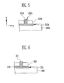
- FIG. 5 is a sectional view of an electrode tab and a tab mounting portion according to still another embodiment of the present invention.
- each of the first and second electrode tabs 220a or 220b is mounted on the tab mounting portion 250a or 250b provided to a protective circuit module 260a and 260b.
- a second alignment portion 251 a or 251 b provided to the tab mounting portion 250a or 250b further includes an end portion 252a or 252b inserted into an opening as a first alignment portion provided to each of the first and second electrode tabs 220a or 220b and then contacted with an outer surface of each of the first and second electrode tabs 220a or 220b.
- the second alignment portion 251a is inserted into the first alignment portion in an X-direction and then fixed by the end portion 252a contacted with the outer surface of each of the first and second electrode tabs 220a.
- the end portion 252a is formed in the shape of a hook protruded in a Y-direction.
- the second alignment portion 251 b is inserted into the first alignment portion and then fixed by the mushroom-shaped end portion 252b.
- the section of the hook-or mushroom-shaped end portion 252a and 252b may be formed greater than that of the opening as the first alignment portion, and accordingly, the second alignment portion 251a or 251b inserted into the opening as the first alignment portion can be firmly fixed.
- the outer surface of the first alignment portion may further include surface roughness.
- the surface roughness may be provided at a portion contacted with the end portion 252a or 252b of the second alignment portion 251 a or 251 b on the outer surface of the first alignment portion. Accordingly, each of the first and second electrode tabs 220a or 220b can be firmly fixed to the tab mounting portion 250a or 250b.
- FIG. 6 is a sectional view of an electrode tab and a tab mounting portion according to still another embodiment of the present invention.
- each of the first and second electrode tabs 230 is mounted on the tab mounting portion 350 of a protective circuit module 360.
- a coupling layer 370 is further included between the tab mounting portion 350 and each of the first and second electrode tabs 320.
- an opening as a first alignment portion may be provided to each of the first and second electrode tabs 320, and a second alignment portion 351 inserted into the first alignment portion may be provided to the tab mounting portion 350.
- the coupling layer 370 is provided to each of the first and second electrode tabs 320, and may be provided at only an edge portion of the opening as the first alignment portion.
- the coupling layer 370 may be made of an adhesive material which allows each of the first and second electrode tabs 320 and the tab mounting portion 350 to be electrically connected to each other and simultaneously allows each of the first and second electrode tabs 320 and the tab mounting portion 350 to be physically fixed to each other.
- the coupling layer 370 may include an Ag paste or conductive adhesive.
- the tab mounting portion 350 may be formed identical to or greater than each of the first and second electrode tabs 320, in consideration of a process margin.
- the coupling layer 370 is provided to the tab mounting portion 350, an unnecessary coupling layer 370 remains around each of the first and second electrode tabs 320 after each of the first and second electrode tabs 320 is mounted on the tab mounting portion 350. Therefore, an external appearance failure may be caused.
- the coupling layer 370 is provided to each of the first and second electrode tabs 320 formed identical to or smaller than the tab mounting portion 350, so that it is possible to prevent an external appearance failure due to the coupling layer 370 and to prevent waste of the unnecessary coupling layer 370, thereby reducing material cost.
Landscapes
- Chemical & Material Sciences (AREA)
- Chemical Kinetics & Catalysis (AREA)
- Electrochemistry (AREA)
- General Chemical & Material Sciences (AREA)
- Engineering & Computer Science (AREA)
- Manufacturing & Machinery (AREA)
- Microelectronics & Electronic Packaging (AREA)
- Connection Of Batteries Or Terminals (AREA)
- Battery Mounting, Suspending (AREA)
Abstract
Description
- An aspect of the present invention relates to a battery pack.
- Recently, battery packs have been variously used as power sources of portable electronic devices. As the portable electronic devices are used in various fields, demands on battery packs are being rapidly increased. The battery packs can be charged/discharged a plurality of times, and accordingly are economically and environmentally efficient. Thus, the use of the battery packs is encouraged.
- As the small size and light weight of electronic devices are required, the small size and light weight of battery packs are also required. However, since a material such as lithium having high reactivity is provided to the inside of the battery pack, the small size and light weight of the battery pack is limited due to the safety of the battery pack. Accordingly, a variety of studies have been conducted to develop a battery pack that can be small in size and light in weight while improving the safety of the battery pack.
- Embodiments provide a battery pack having a new electrode tab.
- Embodiments also provide a battery pack capable of improving process efficiency by applying a new method for attaching a protective circuit module.
- According to an aspect of the present invention, there is provided a battery pack, including: an electrode assembly configured to have first and second electrode tabs; a battery case configured to accommodate the electrode assembly therein so that the first and second electrode tabs are protruded to the outside of the battery case; and a protective circuit module configured to have a plurality of tab mounting portions coupled to the respective first and second electrode tabs, wherein a first alignment portion is provided to each of the first and second electrode tabs, and a second alignment portion contacted with the first alignment portion is provided to each tab mounting portion.
- The first alignment portion may include an opening.
- The second alignment portion may include a projection having a section corresponding to the opening.
- The projection may be protruded by a first length to the outside of the opening by being inserted into the opening. The first length may be 0.5 to 1 mm.
- The projection may include an end portion protruded to the outside of the first alignment portion. The end portion may have a hook or mushroom shape.
- The tab mounting portion may be provided to have a size corresponding to that of each of the first and second electrode tabs. The tab mounting portion may be provided inside the protective circuit module, or may be protruded to the outside of the protective circuit module so as to face each of the first and second electrode tabs.
- A coupling layer may be further included between the tab mounting portion and each of the first and second electrode tabs.
- The coupling layer may be provided to each of the first and second electrode tabs. The coupling layer may be provided around the first alignment portion.
- The coupling layer may include an Ag paste or conductive adhesive.
- As described above, according to the present invention, it is possible to provide a battery pack having a new electrode tab.
- Further, it is possible to provide a battery pack capable of improving process efficiency by applying a new method for attaching a protective circuit module.
- At least some of the above and other features of the invention are set out in the claims.
- Example embodiments of the present invention will now be described more fully hereinafter with reference to the accompanying drawings; however, they may be embodied in different forms and should not be construed as limited to the embodiments set forth herein. Rather, these embodiments are provided so that this disclosure will be thorough and complete, and will fully convey the scope of the example embodiments of the present invention to those skilled in the art.
- In the drawing figures, dimensions may be exaggerated for clarity of illustration. It will be understood that when an element is referred to as being "between" two elements, it can be the only element between the two elements, or one or more intervening elements may also be present. Like reference numerals refer to like elements throughout.
-
FIG. 1 is a perspective view of a battery pack according to an embodiment of the present invention. -
FIG. 2 is an exploded perspective view of the battery pack shown inFIG. 1 . -
FIG. 3A is a sectional view taken along line I-I ofFIG. 1 . -
FIG. 3B is an exploded view ofFIG. 3A . -
FIG. 4 is a sectional view of an electrode tab and a tab mounting portion according to another embodiment of the present invention. -
FIG. 5 is a sectional view of an electrode tab and a tab mounting portion according to still another embodiment of the present invention. -
FIG. 6 is a sectional view of an electrode tab and a tab mounting portion according to still another embodiment of the present invention. - In the following detailed description, only certain example embodiments of the present invention have been shown and described, simply by way of illustration. As those skilled in the art would realize, the described embodiments may be modified in various different ways, all without departing from the scope of the present invention. Accordingly, the drawings and description are to be regarded as illustrative in nature and not restrictive. In addition, when an element is referred to as being "on" another element, it can be directly on the another element or be indirectly on the another element with one or more intervening elements interposed therebetween. Also, when an element is referred to as being "connected to" another element, it can be directly connected to the another element or be indirectly connected to the another element with one or more intervening elements interposed therebetween. Hereinafter, like reference numerals refer to like elements.
-
FIG. 1 is a perspective view of a battery pack according to an embodiment of the present invention.FIG. 2 is an exploded perspective view of the battery pack shown inFIG. 1 . - Referring to
FIGS. 1 and 2 , thebattery pack 100 according to this embodiment includes an electrode assembly configured to have first andsecond electrode tabs battery case 130 configured to accommodate the electrode assembly therein so that the first andsecond electrode tabs battery case 130; and aprotective circuit module 160 configured to have a plurality oftab mounting portions 150 coupled to the respective first andsecond electrode tabs first alignment portion 121 is provided to each of the first andsecond electrode tabs second alignment portion 151 contacted with thefirst alignment portion 121 is provided to eachtab mounting portion 150. - In this embodiment, the
battery pack 100 is configured with asecondary battery 110 and theprotective module 160 electrically connected to thesecondary battery 110. The first andsecond electrode tabs battery case 130 in thesecondary battery 110. The first andsecond electrode tabs tab mounting portions 150 of theprotective circuit module 160. - In this embodiment, the
secondary battery 110 is configured with thebattery case 130, and the electrode assembly and an electrolyte, which are accommodated in thebattery case 130. The electrode assembly is configured with first and second electrode plates having different polarities, and a separator. For example, the first electrode plate may be a positive electrode plate formed by coating a positive electrode active material including lithium on a base material, and the second electrode plate may be a negative electrode plate formed by coating a negative electrode active material including carbon on a base material. The separator is interposed between the first and second electrode plates so as to prevent the first and second electrode plates from coming in direct contact with each other. The separator may include a plurality of pores that form a passage of ions or the electrolyte. - In the present embodiment, the electrolyte is accommodated together with the electrode assembly in the
battery case 130. In this case, the electrolyte allows current to easily flow between the first and second electrode plates. For example, the electrolyte may include a lithium salt serving as a supply source of lithium ions, and a non-aqueous organic solvent serving as a medium through which ions associated with an electrochemical reaction can move. - After the electrode assembly and the electrolyte are accommodated in the
battery case 130, thebattery case 130 may be sealed along an edge portion thereof. In this case, the edge portion of thebattery case 130 is sealed after the first andsecond electrode tabs battery case 130 through the edge portion of thebattery case 130. Thebattery case 130 may be a pouch-type battery case in which polymer resin, thin-film metal and polymer resin are laminated in a plurality of layers. For example, thesecondary battery 110 according to this embodiment is a pouch-type secondary battery. - In the present embodiment, the
battery pack 100 includes theprotective circuit module 160 provided adjacent to the first andsecond electrode tabs protective circuit module 160 is electrically connected to the first andsecond electrode tabs battery pack 100. Theprotective circuit module 160 isprovided with a secondary element, a circuit and the like, which constitute a safety device of thebattery pack 100. The plurality oftab mounting portions 150 connected to the respective first andsecond electrode tabs protective circuit module 160. - The
tab mounting portion 150 may be provided to have a size corresponding to that of each of the first andsecond electrode tabs tab mounting portion 150 may be provided inside theprotective circuit module 160, or may be protruded to the outside of theprotective circuit module 160 so as to face the respective first andsecond electrode tabs tab mounting portions 150 are mounted inside theprotective circuit module 160 will be described. - The first and
second electrode tabs 120 are provided on the respectivetab mounting portions 150. The width L1 of thetab mounting portion 150 may be formed identical to or greater than the width L2 of each of the first andsecond electrode tabs 120. For example, the width L1 of thetab mounting portion 150 may be about 5 to 7mm, and the width L2 of each of the first andsecond electrode tabs 120 may be about 5 to 6mm. That is, the width L1 of thetab mounting portion 150 may be 1.2 times or less of the width L2 of each of the first andsecond electrode tabs 120. - For example, in this embodiment, the
first alignment portion 121 is provided to each of the first andsecond electrode tabs 120, and thesecond alignment portion 151 contacted with thefirst alignment portion 121 is provided to thetab mounting portion 150. The first andsecond electrode tabs 120 are mounted on the respectivetab mounting portion 150 and then fixed through a process such as welding. In this case, the positions of the first andsecond electrode tabs 120 can be easily aligned by the first andsecond alignment portions tab mounting portion 150 corresponding to each of the first andsecond electrode tabs 120. After each of the first andsecond electrode tabs 120 is mounted on thetab mounting portion 150, each of the first andsecond electrode tabs 120 is fixed to thetab mounting portion 150 by coupling the first andsecond alignment portions tab mounting portion 150. Further, the space occupied by thetab mounting portion 150 is decreased in theprotective circuit module 160, and thus it is possible to efficiently use a space for a protective element, etc., mounted on theprotective circuit module 160. - Generally, in a battery pack having first and second electrode tabs protruded to the outside of a battery case, a protective circuit module is provided corresponding to the width of a secondary battery. That is, the width of the protective circuit module is provided corresponding to that of a surface on which the first and second electrode tabs are protruded in the secondary battery. In this case, each of the first and second electrode tabs is electrically connected to a tab mounting portion of the protective circuit module through welding. As the width of the secondary battery is variously changed, it is not easy to align the position between the tab mounting portion of the protective circuit module and each of the first and second electrode tabs. Further, the tab mounting portion is frequently misaligned with each of the first and second electrode tabs, and therefore, a failure occurs in the welding process. As a result, the process efficiency is decreased. Accordingly, the size of the tab mounting portion, e.g., the width of the tab mounting portion should be 1.6 times or more that the width of each of the first and second electrode tabs. Therefore, production cost is increased, and it is difficult to secure welding quality. Further, a high-specification facility and a jig are required to weld each of the first and second electrode tabs to the tab mounting portion.
- However, in the battery pack according to this embodiment, the position between the tab mounting portion and each of the first and second electrode tabs can be easily aligned, thereby improving the process efficiency. Further, the size of the tab mounting portion can be provided corresponding to that of each of the first and second electrode tabs. Furthermore, in the battery pack according to this embodiment, the position between the tab mounting portion and each of the first and second electrode tabs can be easily aligned without using a separate jig, so that it is possible to prevent occurrence of a failure and to secure high welding quality.
-
FIG. 3A is a sectional view taken along line I-I ofFIG. 1 .FIG. 3B is an exploded view ofFIG. 3A . - Referring to
FIGS. 3A and 3B , thefirst alignment portion 121 provided to each of the first andsecond electrode tabs 120 and thesecond alignment portion 151 provided to thetab mounting portion 150 may be coupled to each other. For example, any one of the first andsecond alignment portions second alignment portions first alignment portion 121 is formed in the shape of an opening and thesecond alignment portion 151 is formed in the shape of a projection having a section corresponding to the opening, the present invention is not limited thereto. - When each of the first and
second electrode tabs 120 is provided on thetab mounting portion 150, the position of each of the first and second electrode tab 10 can be easily aligned with thetab mounting portion 150 by the first andsecond alignment portions second alignment portion 151 is inserted into the opening as thefirst alignment portion 121, each of the first andsecond electrode tabs 120 is fixed to thetab mounting portion 150, thereby easily performing a subsequent welding process. - After each of the first and
second electrode tabs 120 is mounted on thetab mounting portion 150, the projection as thesecond alignment portion 151 may be protruded to the outside of the opening by being inserted into the opening as thefirst alignment portion 121. When assuming that the length of thesecond alignment portion 151 protruded from an outer surface of thefirst alignment portion 121 is a first length S, the first length S may be about 0.5 to 1 mm. The portion of the second alignment portion comprising a first length S may be referred to as an end portion. In the welding process between thetab mounting portion 150 and each of the first andsecond electrode tab 120, the welding process may be performed after the first length S of thesecond alignment portion 151 is pressed. In a case where the first length S is less than 0.5mm, each of the first andsecond electrode tab 120 is not fixed to thetab mounting portion 150 and easily separated from thetab mounting portion 150 after thesecond alignment portion 151 is inserted into thefirst alignment portion 121. Therefore, it is difficult to secure welding quality. For example, each of the first andsecond electrode tabs 120 and thetab mounting portion 150 may be made of metal that is an electrical conductor, and therefore, the frictional force between thetab mounting portion 150 and each of the first andsecond electrode tabs 120 is low due to properties of the metal. Accordingly, the first length S is preferably maintained as a predetermined length in order to maintain the coupling between the first andsecond alignment portions second alignment portion 151 is inserted into thefirst alignment portion 121. The first length S may be 0.5mm or more. In addition, the first length S is preferably less than 1mm. In a case where the first length S exceeds 1mm, at least one portion of the first length S is pressed, and the welding process is then performed in order to secure the welding quality before the welding process is performed. However, in a case where the first length S is longer than a predetermined length, a portion to be pressed in the first length S is increased. Therefore, unnecessary energy is wasted, thereby lowering the process efficiency. That is, the first length S is preferably 0.5 to 1mm, in consideration of both the fixing force between thetab mounting portion 150 and each of the first andsecond electrode tabs 120 and the efficiency of the subsequent welding process. For example, the first length S is most preferably 0.8mm. - Hereinafter, other embodiments of the present invention will be described with reference to
FIGS. 4 to 6 . Contents of these embodiments, except the following contents, are similar to those of the embodiment described with reference toFIGS. 1 to 3 , and therefore, their detailed descriptions will be omitted. -
FIG. 4 is a sectional view of an electrode tab and a tab mounting portion according to another embodiment of the present invention.FIG. 5 is a sectional view of an electrode tab and a tab mounting portion according to still another embodiment of the present invention. - Referring to
FIGS. 4 and5 , each of the first andsecond electrode tabs tab mounting portion protective circuit module second alignment portion tab mounting portion end portion second electrode tabs second electrode tabs - In
FIG. 5 , thesecond alignment portion 251a is inserted into the first alignment portion in an X-direction and then fixed by theend portion 252a contacted with the outer surface of each of the first andsecond electrode tabs 220a. In this case, theend portion 252a is formed in the shape of a hook protruded in a Y-direction. InFIG. 6 , thesecond alignment portion 251 b is inserted into the first alignment portion and then fixed by the mushroom-shapedend portion 252b. The section of the hook-or mushroom-shapedend portion second alignment portion end portion second alignment portion second electrode tabs tab mounting portion -
FIG. 6 is a sectional view of an electrode tab and a tab mounting portion according to still another embodiment of the present invention. - Referring to
FIG. 6 , each of the first and second electrode tabs 230 is mounted on thetab mounting portion 350 of aprotective circuit module 360. In this case, acoupling layer 370 is further included between thetab mounting portion 350 and each of the first andsecond electrode tabs 320. Particularly, an opening as a first alignment portion may be provided to each of the first andsecond electrode tabs 320, and asecond alignment portion 351 inserted into the first alignment portion may be provided to thetab mounting portion 350. In this case, thecoupling layer 370 is provided to each of the first andsecond electrode tabs 320, and may be provided at only an edge portion of the opening as the first alignment portion. Thecoupling layer 370 may be made of an adhesive material which allows each of the first andsecond electrode tabs 320 and thetab mounting portion 350 to be electrically connected to each other and simultaneously allows each of the first andsecond electrode tabs 320 and thetab mounting portion 350 to be physically fixed to each other. For example, thecoupling layer 370 may include an Ag paste or conductive adhesive. - When each of the first and
second electrode tabs 320 is provided on thetab mounting portion 350, thetab mounting portion 350 may be formed identical to or greater than each of the first andsecond electrode tabs 320, in consideration of a process margin. In a case where thecoupling layer 370 is provided to thetab mounting portion 350, anunnecessary coupling layer 370 remains around each of the first andsecond electrode tabs 320 after each of the first andsecond electrode tabs 320 is mounted on thetab mounting portion 350. Therefore, an external appearance failure may be caused. Accordingly, thecoupling layer 370 is provided to each of the first andsecond electrode tabs 320 formed identical to or smaller than thetab mounting portion 350, so that it is possible to prevent an external appearance failure due to thecoupling layer 370 and to prevent waste of theunnecessary coupling layer 370, thereby reducing material cost. - Example embodiments have been disclosed herein, and although specific terms are employed, they are used and are to be interpreted in a generic and descriptive sense only and not for purpose of limitation. In some instances, as would be apparent to one of ordinary skill in the art as of the filing of the present application, features, characteristics, and/or elements described in connection with a particular embodiment may be used singly or in combination with features, characteristics, and/or elements described in connection with other embodiments unless otherwise specifically indicated. Accordingly, it will be understood by those of skill in the art that various changes in form and details may be made without departing from the scope of the present invention as set forth in the following claims.
Claims (15)
- A battery pack (100) comprising:a battery case (130) ;an electrode assembly accommodated inside the battery case (130) and comprising an electrode tab (120), that protrudes outside of the battery case (130) and comprises a first alignment portion (121); anda protective circuit module (160) comprising a tab mounting portion (150) that includes a second alignment portion (151);wherein the first alignment portion (121) is coupled with the second alignment portion (151).
- A battery pack (100) according to claim 1, wherein the first alignment portion (121) comprises an opening.
- A battery pack (100) according to claim 2, wherein the second alignment portion (151) comprises a projection, and the projection (151) is inserted into the first opening (121).
- A battery pack (100) according to claim 3, wherein the projection (151) comprises an end portion which protrudes beyond the opening (121).
- A battery pack (100) according to claim 4, wherein the length (S) of the end portion (121) is between 0.5 to 1 mm, and the length (S) of the end portion is optionally 0.8mm.
- A battery pack (100) according to claim 4 or any claim dependent thereon, wherein the end portion (252a, 252b) comprises a radius larger than the radius of the opening (121).
- A battery pack (100) according to claim 4 or any claim dependent thereon, wherein the end portion (252a, 252b) comprises a hook or a mushroom shaped profile.
- A battery pack (100) according to any preceding claim, wherein the tab mounting portion (150) is situated inside the protective circuit module.
- A battery pack (100) according to any preceding claim, wherein the tab mounting portion (150) at least partially extends to an outer surface of the protective circuit module to face the electrode tab (120).
- A battery pack (100) according to any preceding claim, wherein the ratio of a width of the tab mounting portion (150) and a width of the electrode tab (120) are equal to or larger than 1 and less than 1.2.
- A battery pack (100) according to any preceding claim, wherein a coupling layer (370) is provided between the tab mounting portion (150) and the electrode tab (120).
- A battery pack (100) according to claim 11, wherein the width of the coupling layer (370) is equal to or smaller than a width of the tab mounting portion (150).
- A battery pack (100) according to claim 11 or 12, wherein the coupling layer (370) comprises an Ag paste or a conductive adhesive.
- A battery pack (100) according to claim 11 or any dependent claim thereon wherein the coupling layer (370) is provided around the first alignment portion (121).
- A battery pack (100) according to claim 11 or any dependent claim thereon wherein the coupling layer (370) is provided on the electrode tab (120).
Applications Claiming Priority (2)
| Application Number | Priority Date | Filing Date | Title |
|---|---|---|---|
| US201361839057P | 2013-06-25 | 2013-06-25 | |
| US14/293,409 US20140377593A1 (en) | 2013-06-25 | 2014-06-02 | Battery pack |
Publications (2)
| Publication Number | Publication Date |
|---|---|
| EP2819218A1 true EP2819218A1 (en) | 2014-12-31 |
| EP2819218B1 EP2819218B1 (en) | 2016-04-20 |
Family
ID=51014165
Family Applications (1)
| Application Number | Title | Priority Date | Filing Date |
|---|---|---|---|
| EP14173984.7A Active EP2819218B1 (en) | 2013-06-25 | 2014-06-25 | Battery pack |
Country Status (4)
| Country | Link |
|---|---|
| US (1) | US20140377593A1 (en) |
| EP (1) | EP2819218B1 (en) |
| JP (1) | JP6465472B2 (en) |
| KR (1) | KR102257674B1 (en) |
Families Citing this family (4)
| Publication number | Priority date | Publication date | Assignee | Title |
|---|---|---|---|---|
| US11043700B2 (en) | 2014-12-26 | 2021-06-22 | Samsung Sdi Co., Ltd. | Non-aqueous electrolyte rechargeable battery |
| KR102331724B1 (en) * | 2015-01-29 | 2021-11-26 | 삼성에스디아이 주식회사 | Method for Manufacturing Secondary Battery |
| CN113328146A (en) * | 2021-06-15 | 2021-08-31 | 多氟多新能源科技有限公司 | Method for stacking PACK of soft package lithium ion battery |
| KR102895754B1 (en) * | 2022-12-29 | 2025-12-03 | 삼성에스디아이 주식회사 | Battery pack and manufacturing method for battery pack |
Citations (3)
| Publication number | Priority date | Publication date | Assignee | Title |
|---|---|---|---|---|
| JP2003208886A (en) * | 2002-01-16 | 2003-07-25 | Mitsubishi Chemicals Corp | Battery |
| US20040257036A1 (en) * | 2003-06-19 | 2004-12-23 | Samsung Sdi Co. Ltd | Secondary battery |
| JP2009163932A (en) * | 2007-12-28 | 2009-07-23 | Sharp Corp | Battery pack |
Family Cites Families (7)
| Publication number | Priority date | Publication date | Assignee | Title |
|---|---|---|---|---|
| KR20060097603A (en) * | 2005-03-09 | 2006-09-14 | 산요덴키가부시키가이샤 | Battery and its manufacturing method |
| KR100614388B1 (en) * | 2005-03-09 | 2006-08-21 | 삼성에스디아이 주식회사 | Protective Circuit Board of Secondary Battery, Secondary Battery Using It and Formation Method |
| KR100601577B1 (en) * | 2005-03-24 | 2006-07-19 | 삼성에스디아이 주식회사 | Secondary battery |
| JP2009123646A (en) * | 2007-11-19 | 2009-06-04 | Sony Corp | Battery pack and battery pack manufacturing method |
| US9130224B2 (en) * | 2009-07-06 | 2015-09-08 | Samsung Sdi Co., Ltd. | Battery pack and method of manufacturing battery pack |
| US9077027B2 (en) * | 2010-03-04 | 2015-07-07 | Samsung Sdi Co., Ltd. | Electrode assembly and secondary battery using the same |
| US8790823B2 (en) * | 2011-02-08 | 2014-07-29 | Samsung Sdi Co., Ltd. | Battery unit and battery pack having less resistance and improved contacts |
-
2014
- 2014-06-02 US US14/293,409 patent/US20140377593A1/en not_active Abandoned
- 2014-06-17 KR KR1020140073700A patent/KR102257674B1/en active Active
- 2014-06-25 JP JP2014130178A patent/JP6465472B2/en active Active
- 2014-06-25 EP EP14173984.7A patent/EP2819218B1/en active Active
Patent Citations (3)
| Publication number | Priority date | Publication date | Assignee | Title |
|---|---|---|---|---|
| JP2003208886A (en) * | 2002-01-16 | 2003-07-25 | Mitsubishi Chemicals Corp | Battery |
| US20040257036A1 (en) * | 2003-06-19 | 2004-12-23 | Samsung Sdi Co. Ltd | Secondary battery |
| JP2009163932A (en) * | 2007-12-28 | 2009-07-23 | Sharp Corp | Battery pack |
Also Published As
| Publication number | Publication date |
|---|---|
| US20140377593A1 (en) | 2014-12-25 |
| KR20150000825A (en) | 2015-01-05 |
| JP6465472B2 (en) | 2019-02-06 |
| EP2819218B1 (en) | 2016-04-20 |
| JP2015008139A (en) | 2015-01-15 |
| KR102257674B1 (en) | 2021-05-28 |
Similar Documents
| Publication | Publication Date | Title |
|---|---|---|
| KR101792572B1 (en) | Battery Cell Having Electrode Coated with Insulating Material | |
| EP2634831B1 (en) | Pouch type secondary battery | |
| KR101483133B1 (en) | Rechargeable battery | |
| US9843066B2 (en) | Thin film battery assemblies | |
| US8658308B2 (en) | Pouch-type secondary battery with insulating member and alignment mark on case | |
| CN103367668A (en) | Rechargeable battery | |
| US20160049696A1 (en) | Battery pack | |
| EP2827406B1 (en) | Rechargeable battery | |
| EP2819218B1 (en) | Battery pack | |
| KR101734327B1 (en) | Pouch type secondary battery | |
| KR102207296B1 (en) | Pouch-typed Battery Cell Comprising Shape-keeping Member | |
| KR20150115358A (en) | Secondary battery | |
| KR20140100085A (en) | Battery pack | |
| KR101893958B1 (en) | Secondary battery | |
| EP2830140B1 (en) | Electrode assembly for a secondary battery | |
| KR20140081105A (en) | Cap Assembly Having Electrode Terminal Protection Member and Battery Cell Comprising the Same | |
| US9240582B2 (en) | Battery pack | |
| KR20160018170A (en) | Secondary Battery | |
| US20150228960A1 (en) | Battery pack | |
| CN106159308A (en) | For the method manufacturing secondary cell | |
| EP2887443A1 (en) | Battery pack | |
| EP4231394A4 (en) | Electrode assembly and manufacturing method therefor, secondary battery, battery module, battery pack, and electrical device | |
| KR20160076030A (en) | Battery Pack Having Biding Portion and Insulative Member | |
| KR20260051526A (en) | Secondary battery and method for manufacturing same, electronic device including same | |
| US9515308B2 (en) | Battery pack |
Legal Events
| Date | Code | Title | Description |
|---|---|---|---|
| PUAI | Public reference made under article 153(3) epc to a published international application that has entered the european phase |
Free format text: ORIGINAL CODE: 0009012 |
|
| 17P | Request for examination filed |
Effective date: 20140625 |
|
| AK | Designated contracting states |
Kind code of ref document: A1 Designated state(s): AL AT BE BG CH CY CZ DE DK EE ES FI FR GB GR HR HU IE IS IT LI LT LU LV MC MK MT NL NO PL PT RO RS SE SI SK SM TR |
|
| AX | Request for extension of the european patent |
Extension state: BA ME |
|
| R17P | Request for examination filed (corrected) |
Effective date: 20150630 |
|
| RBV | Designated contracting states (corrected) |
Designated state(s): AL AT BE BG CH CY CZ DE DK EE ES FI FR GB GR HR HU IE IS IT LI LT LU LV MC MK MT NL NO PL PT RO RS SE SI SK SM TR |
|
| RIC1 | Information provided on ipc code assigned before grant |
Ipc: H01M 2/02 20060101ALN20150813BHEP Ipc: H01M 2/30 20060101AFI20150813BHEP Ipc: H01M 10/04 20060101ALI20150813BHEP Ipc: H01M 10/052 20100101ALN20150813BHEP Ipc: H01M 10/058 20100101ALN20150813BHEP Ipc: H01M 10/42 20060101ALI20150813BHEP |
|
| GRAP | Despatch of communication of intention to grant a patent |
Free format text: ORIGINAL CODE: EPIDOSNIGR1 |
|
| RIC1 | Information provided on ipc code assigned before grant |
Ipc: H01M 2/30 20060101AFI20150929BHEP Ipc: H01M 2/02 20060101ALN20150929BHEP Ipc: H01M 10/42 20060101ALI20150929BHEP Ipc: H01M 10/04 20060101ALI20150929BHEP Ipc: H01M 10/058 20100101ALN20150929BHEP Ipc: H01M 10/052 20100101ALN20150929BHEP |
|
| INTG | Intention to grant announced |
Effective date: 20151014 |
|
| RIN1 | Information on inventor provided before grant (corrected) |
Inventor name: HONG, SUNG-HO |
|
| GRAS | Grant fee paid |
Free format text: ORIGINAL CODE: EPIDOSNIGR3 |
|
| GRAA | (expected) grant |
Free format text: ORIGINAL CODE: 0009210 |
|
| AK | Designated contracting states |
Kind code of ref document: B1 Designated state(s): AL AT BE BG CH CY CZ DE DK EE ES FI FR GB GR HR HU IE IS IT LI LT LU LV MC MK MT NL NO PL PT RO RS SE SI SK SM TR |
|
| REG | Reference to a national code |
Ref country code: GB Ref legal event code: FG4D |
|
| REG | Reference to a national code |
Ref country code: CH Ref legal event code: EP |
|
| REG | Reference to a national code |
Ref country code: AT Ref legal event code: REF Ref document number: 793302 Country of ref document: AT Kind code of ref document: T Effective date: 20160515 |
|
| REG | Reference to a national code |
Ref country code: FR Ref legal event code: PLFP Year of fee payment: 3 |
|
| REG | Reference to a national code |
Ref country code: IE Ref legal event code: FG4D |
|
| REG | Reference to a national code |
Ref country code: DE Ref legal event code: R096 Ref document number: 602014001552 Country of ref document: DE |
|
| REG | Reference to a national code |
Ref country code: LT Ref legal event code: MG4D |
|
| REG | Reference to a national code |
Ref country code: AT Ref legal event code: MK05 Ref document number: 793302 Country of ref document: AT Kind code of ref document: T Effective date: 20160420 |
|
| REG | Reference to a national code |
Ref country code: NL Ref legal event code: MP Effective date: 20160420 |
|
| PG25 | Lapsed in a contracting state [announced via postgrant information from national office to epo] |
Ref country code: NL Free format text: LAPSE BECAUSE OF FAILURE TO SUBMIT A TRANSLATION OF THE DESCRIPTION OR TO PAY THE FEE WITHIN THE PRESCRIBED TIME-LIMIT Effective date: 20160420 Ref country code: PL Free format text: LAPSE BECAUSE OF FAILURE TO SUBMIT A TRANSLATION OF THE DESCRIPTION OR TO PAY THE FEE WITHIN THE PRESCRIBED TIME-LIMIT Effective date: 20160420 Ref country code: FI Free format text: LAPSE BECAUSE OF FAILURE TO SUBMIT A TRANSLATION OF THE DESCRIPTION OR TO PAY THE FEE WITHIN THE PRESCRIBED TIME-LIMIT Effective date: 20160420 Ref country code: NO Free format text: LAPSE BECAUSE OF FAILURE TO SUBMIT A TRANSLATION OF THE DESCRIPTION OR TO PAY THE FEE WITHIN THE PRESCRIBED TIME-LIMIT Effective date: 20160720 Ref country code: LT Free format text: LAPSE BECAUSE OF FAILURE TO SUBMIT A TRANSLATION OF THE DESCRIPTION OR TO PAY THE FEE WITHIN THE PRESCRIBED TIME-LIMIT Effective date: 20160420 |
|
| PG25 | Lapsed in a contracting state [announced via postgrant information from national office to epo] |
Ref country code: HR Free format text: LAPSE BECAUSE OF FAILURE TO SUBMIT A TRANSLATION OF THE DESCRIPTION OR TO PAY THE FEE WITHIN THE PRESCRIBED TIME-LIMIT Effective date: 20160420 Ref country code: GR Free format text: LAPSE BECAUSE OF FAILURE TO SUBMIT A TRANSLATION OF THE DESCRIPTION OR TO PAY THE FEE WITHIN THE PRESCRIBED TIME-LIMIT Effective date: 20160721 Ref country code: RS Free format text: LAPSE BECAUSE OF FAILURE TO SUBMIT A TRANSLATION OF THE DESCRIPTION OR TO PAY THE FEE WITHIN THE PRESCRIBED TIME-LIMIT Effective date: 20160420 Ref country code: LV Free format text: LAPSE BECAUSE OF FAILURE TO SUBMIT A TRANSLATION OF THE DESCRIPTION OR TO PAY THE FEE WITHIN THE PRESCRIBED TIME-LIMIT Effective date: 20160420 Ref country code: AT Free format text: LAPSE BECAUSE OF FAILURE TO SUBMIT A TRANSLATION OF THE DESCRIPTION OR TO PAY THE FEE WITHIN THE PRESCRIBED TIME-LIMIT Effective date: 20160420 Ref country code: PT Free format text: LAPSE BECAUSE OF FAILURE TO SUBMIT A TRANSLATION OF THE DESCRIPTION OR TO PAY THE FEE WITHIN THE PRESCRIBED TIME-LIMIT Effective date: 20160822 Ref country code: SE Free format text: LAPSE BECAUSE OF FAILURE TO SUBMIT A TRANSLATION OF THE DESCRIPTION OR TO PAY THE FEE WITHIN THE PRESCRIBED TIME-LIMIT Effective date: 20160420 Ref country code: ES Free format text: LAPSE BECAUSE OF FAILURE TO SUBMIT A TRANSLATION OF THE DESCRIPTION OR TO PAY THE FEE WITHIN THE PRESCRIBED TIME-LIMIT Effective date: 20160420 |
|
| PG25 | Lapsed in a contracting state [announced via postgrant information from national office to epo] |
Ref country code: BE Free format text: LAPSE BECAUSE OF FAILURE TO SUBMIT A TRANSLATION OF THE DESCRIPTION OR TO PAY THE FEE WITHIN THE PRESCRIBED TIME-LIMIT Effective date: 20160420 Ref country code: IT Free format text: LAPSE BECAUSE OF FAILURE TO SUBMIT A TRANSLATION OF THE DESCRIPTION OR TO PAY THE FEE WITHIN THE PRESCRIBED TIME-LIMIT Effective date: 20160420 |
|
| REG | Reference to a national code |
Ref country code: DE Ref legal event code: R097 Ref document number: 602014001552 Country of ref document: DE |
|
| PG25 | Lapsed in a contracting state [announced via postgrant information from national office to epo] |
Ref country code: DK Free format text: LAPSE BECAUSE OF FAILURE TO SUBMIT A TRANSLATION OF THE DESCRIPTION OR TO PAY THE FEE WITHIN THE PRESCRIBED TIME-LIMIT Effective date: 20160420 Ref country code: SK Free format text: LAPSE BECAUSE OF FAILURE TO SUBMIT A TRANSLATION OF THE DESCRIPTION OR TO PAY THE FEE WITHIN THE PRESCRIBED TIME-LIMIT Effective date: 20160420 Ref country code: EE Free format text: LAPSE BECAUSE OF FAILURE TO SUBMIT A TRANSLATION OF THE DESCRIPTION OR TO PAY THE FEE WITHIN THE PRESCRIBED TIME-LIMIT Effective date: 20160420 Ref country code: CZ Free format text: LAPSE BECAUSE OF FAILURE TO SUBMIT A TRANSLATION OF THE DESCRIPTION OR TO PAY THE FEE WITHIN THE PRESCRIBED TIME-LIMIT Effective date: 20160420 Ref country code: MC Free format text: LAPSE BECAUSE OF FAILURE TO SUBMIT A TRANSLATION OF THE DESCRIPTION OR TO PAY THE FEE WITHIN THE PRESCRIBED TIME-LIMIT Effective date: 20160420 Ref country code: RO Free format text: LAPSE BECAUSE OF FAILURE TO SUBMIT A TRANSLATION OF THE DESCRIPTION OR TO PAY THE FEE WITHIN THE PRESCRIBED TIME-LIMIT Effective date: 20160420 |
|
| PLBE | No opposition filed within time limit |
Free format text: ORIGINAL CODE: 0009261 |
|
| STAA | Information on the status of an ep patent application or granted ep patent |
Free format text: STATUS: NO OPPOSITION FILED WITHIN TIME LIMIT |
|
| PG25 | Lapsed in a contracting state [announced via postgrant information from national office to epo] |
Ref country code: SM Free format text: LAPSE BECAUSE OF FAILURE TO SUBMIT A TRANSLATION OF THE DESCRIPTION OR TO PAY THE FEE WITHIN THE PRESCRIBED TIME-LIMIT Effective date: 20160420 |
|
| REG | Reference to a national code |
Ref country code: IE Ref legal event code: MM4A |
|
| 26N | No opposition filed |
Effective date: 20170123 |
|
| REG | Reference to a national code |
Ref country code: FR Ref legal event code: PLFP Year of fee payment: 4 |
|
| PG25 | Lapsed in a contracting state [announced via postgrant information from national office to epo] |
Ref country code: IE Free format text: LAPSE BECAUSE OF NON-PAYMENT OF DUE FEES Effective date: 20160625 Ref country code: SI Free format text: LAPSE BECAUSE OF FAILURE TO SUBMIT A TRANSLATION OF THE DESCRIPTION OR TO PAY THE FEE WITHIN THE PRESCRIBED TIME-LIMIT Effective date: 20160420 |
|
| REG | Reference to a national code |
Ref country code: CH Ref legal event code: PL |
|
| PG25 | Lapsed in a contracting state [announced via postgrant information from national office to epo] |
Ref country code: LI Free format text: LAPSE BECAUSE OF NON-PAYMENT OF DUE FEES Effective date: 20170630 Ref country code: CH Free format text: LAPSE BECAUSE OF NON-PAYMENT OF DUE FEES Effective date: 20170630 |
|
| REG | Reference to a national code |
Ref country code: FR Ref legal event code: PLFP Year of fee payment: 5 |
|
| PG25 | Lapsed in a contracting state [announced via postgrant information from national office to epo] |
Ref country code: HU Free format text: LAPSE BECAUSE OF FAILURE TO SUBMIT A TRANSLATION OF THE DESCRIPTION OR TO PAY THE FEE WITHIN THE PRESCRIBED TIME-LIMIT; INVALID AB INITIO Effective date: 20140625 |
|
| PG25 | Lapsed in a contracting state [announced via postgrant information from national office to epo] |
Ref country code: CY Free format text: LAPSE BECAUSE OF FAILURE TO SUBMIT A TRANSLATION OF THE DESCRIPTION OR TO PAY THE FEE WITHIN THE PRESCRIBED TIME-LIMIT Effective date: 20160420 Ref country code: IS Free format text: LAPSE BECAUSE OF FAILURE TO SUBMIT A TRANSLATION OF THE DESCRIPTION OR TO PAY THE FEE WITHIN THE PRESCRIBED TIME-LIMIT Effective date: 20160420 Ref country code: MT Free format text: LAPSE BECAUSE OF NON-PAYMENT OF DUE FEES Effective date: 20160630 Ref country code: LU Free format text: LAPSE BECAUSE OF NON-PAYMENT OF DUE FEES Effective date: 20160625 Ref country code: MK Free format text: LAPSE BECAUSE OF FAILURE TO SUBMIT A TRANSLATION OF THE DESCRIPTION OR TO PAY THE FEE WITHIN THE PRESCRIBED TIME-LIMIT Effective date: 20160420 |
|
| PG25 | Lapsed in a contracting state [announced via postgrant information from national office to epo] |
Ref country code: BG Free format text: LAPSE BECAUSE OF FAILURE TO SUBMIT A TRANSLATION OF THE DESCRIPTION OR TO PAY THE FEE WITHIN THE PRESCRIBED TIME-LIMIT Effective date: 20160420 |
|
| PG25 | Lapsed in a contracting state [announced via postgrant information from national office to epo] |
Ref country code: TR Free format text: LAPSE BECAUSE OF FAILURE TO SUBMIT A TRANSLATION OF THE DESCRIPTION OR TO PAY THE FEE WITHIN THE PRESCRIBED TIME-LIMIT Effective date: 20160420 Ref country code: AL Free format text: LAPSE BECAUSE OF FAILURE TO SUBMIT A TRANSLATION OF THE DESCRIPTION OR TO PAY THE FEE WITHIN THE PRESCRIBED TIME-LIMIT Effective date: 20160420 |
|
| REG | Reference to a national code |
Ref country code: DE Ref legal event code: R079 Ref document number: 602014001552 Country of ref document: DE Free format text: PREVIOUS MAIN CLASS: H01M0002300000 Ipc: H01M0050543000 |
|
| P01 | Opt-out of the competence of the unified patent court (upc) registered |
Effective date: 20230528 |
|
| PGFP | Annual fee paid to national office [announced via postgrant information from national office to epo] |
Ref country code: DE Payment date: 20250604 Year of fee payment: 12 |
|
| PGFP | Annual fee paid to national office [announced via postgrant information from national office to epo] |
Ref country code: GB Payment date: 20250529 Year of fee payment: 12 |
|
| PGFP | Annual fee paid to national office [announced via postgrant information from national office to epo] |
Ref country code: FR Payment date: 20250610 Year of fee payment: 12 |