EP2819210A1 - Battery module - Google Patents
Battery module Download PDFInfo
- Publication number
- EP2819210A1 EP2819210A1 EP14172642.2A EP14172642A EP2819210A1 EP 2819210 A1 EP2819210 A1 EP 2819210A1 EP 14172642 A EP14172642 A EP 14172642A EP 2819210 A1 EP2819210 A1 EP 2819210A1
- Authority
- EP
- European Patent Office
- Prior art keywords
- battery module
- end plate
- bush member
- plate
- battery
- Prior art date
- Legal status (The legal status is an assumption and is not a legal conclusion. Google has not performed a legal analysis and makes no representation as to the accuracy of the status listed.)
- Granted
Links
- 239000000463 material Substances 0.000 claims description 8
- 230000013011 mating Effects 0.000 claims description 3
- 238000003466 welding Methods 0.000 description 10
- 230000003252 repetitive effect Effects 0.000 description 5
- 230000008878 coupling Effects 0.000 description 4
- 238000010168 coupling process Methods 0.000 description 4
- 238000005859 coupling reaction Methods 0.000 description 4
- 238000005452 bending Methods 0.000 description 3
- PXHVJJICTQNCMI-UHFFFAOYSA-N Nickel Chemical compound [Ni] PXHVJJICTQNCMI-UHFFFAOYSA-N 0.000 description 2
- 238000010586 diagram Methods 0.000 description 2
- 239000003792 electrolyte Substances 0.000 description 2
- 229910052751 metal Inorganic materials 0.000 description 2
- 239000002184 metal Substances 0.000 description 2
- 229910000838 Al alloy Inorganic materials 0.000 description 1
- RYGMFSIKBFXOCR-UHFFFAOYSA-N Copper Chemical compound [Cu] RYGMFSIKBFXOCR-UHFFFAOYSA-N 0.000 description 1
- 229910000881 Cu alloy Inorganic materials 0.000 description 1
- WHXSMMKQMYFTQS-UHFFFAOYSA-N Lithium Chemical compound [Li] WHXSMMKQMYFTQS-UHFFFAOYSA-N 0.000 description 1
- HBBGRARXTFLTSG-UHFFFAOYSA-N Lithium ion Chemical compound [Li+] HBBGRARXTFLTSG-UHFFFAOYSA-N 0.000 description 1
- BQCADISMDOOEFD-UHFFFAOYSA-N Silver Chemical compound [Ag] BQCADISMDOOEFD-UHFFFAOYSA-N 0.000 description 1
- 229910000831 Steel Inorganic materials 0.000 description 1
- 229910052782 aluminium Inorganic materials 0.000 description 1
- XAGFODPZIPBFFR-UHFFFAOYSA-N aluminium Chemical compound [Al] XAGFODPZIPBFFR-UHFFFAOYSA-N 0.000 description 1
- 229910052802 copper Inorganic materials 0.000 description 1
- 239000010949 copper Substances 0.000 description 1
- PCHJSUWPFVWCPO-UHFFFAOYSA-N gold Chemical compound [Au] PCHJSUWPFVWCPO-UHFFFAOYSA-N 0.000 description 1
- 229910052737 gold Inorganic materials 0.000 description 1
- 239000010931 gold Substances 0.000 description 1
- 229910052744 lithium Inorganic materials 0.000 description 1
- 229910001416 lithium ion Inorganic materials 0.000 description 1
- 239000007769 metal material Substances 0.000 description 1
- 238000000034 method Methods 0.000 description 1
- 229910052759 nickel Inorganic materials 0.000 description 1
- 239000011255 nonaqueous electrolyte Substances 0.000 description 1
- 229920000642 polymer Polymers 0.000 description 1
- 238000003825 pressing Methods 0.000 description 1
- 229910052709 silver Inorganic materials 0.000 description 1
- 239000004332 silver Substances 0.000 description 1
- 239000010959 steel Substances 0.000 description 1
- 230000008961 swelling Effects 0.000 description 1
Images


Classifications
-
- H—ELECTRICITY
- H01—ELECTRIC ELEMENTS
- H01M—PROCESSES OR MEANS, e.g. BATTERIES, FOR THE DIRECT CONVERSION OF CHEMICAL ENERGY INTO ELECTRICAL ENERGY
- H01M50/00—Constructional details or processes of manufacture of the non-active parts of electrochemical cells other than fuel cells, e.g. hybrid cells
- H01M50/20—Mountings; Secondary casings or frames; Racks, modules or packs; Suspension devices; Shock absorbers; Transport or carrying devices; Holders
- H01M50/204—Racks, modules or packs for multiple batteries or multiple cells
- H01M50/207—Racks, modules or packs for multiple batteries or multiple cells characterised by their shape
- H01M50/209—Racks, modules or packs for multiple batteries or multiple cells characterised by their shape adapted for prismatic or rectangular cells
-
- H—ELECTRICITY
- H01—ELECTRIC ELEMENTS
- H01M—PROCESSES OR MEANS, e.g. BATTERIES, FOR THE DIRECT CONVERSION OF CHEMICAL ENERGY INTO ELECTRICAL ENERGY
- H01M50/00—Constructional details or processes of manufacture of the non-active parts of electrochemical cells other than fuel cells, e.g. hybrid cells
- H01M50/10—Primary casings; Jackets or wrappings
-
- H—ELECTRICITY
- H01—ELECTRIC ELEMENTS
- H01M—PROCESSES OR MEANS, e.g. BATTERIES, FOR THE DIRECT CONVERSION OF CHEMICAL ENERGY INTO ELECTRICAL ENERGY
- H01M50/00—Constructional details or processes of manufacture of the non-active parts of electrochemical cells other than fuel cells, e.g. hybrid cells
- H01M50/20—Mountings; Secondary casings or frames; Racks, modules or packs; Suspension devices; Shock absorbers; Transport or carrying devices; Holders
- H01M50/218—Mountings; Secondary casings or frames; Racks, modules or packs; Suspension devices; Shock absorbers; Transport or carrying devices; Holders characterised by the material
- H01M50/22—Mountings; Secondary casings or frames; Racks, modules or packs; Suspension devices; Shock absorbers; Transport or carrying devices; Holders characterised by the material of the casings or racks
- H01M50/222—Inorganic material
- H01M50/224—Metals
-
- H—ELECTRICITY
- H01—ELECTRIC ELEMENTS
- H01M—PROCESSES OR MEANS, e.g. BATTERIES, FOR THE DIRECT CONVERSION OF CHEMICAL ENERGY INTO ELECTRICAL ENERGY
- H01M50/00—Constructional details or processes of manufacture of the non-active parts of electrochemical cells other than fuel cells, e.g. hybrid cells
- H01M50/20—Mountings; Secondary casings or frames; Racks, modules or packs; Suspension devices; Shock absorbers; Transport or carrying devices; Holders
- H01M50/244—Secondary casings; Racks; Suspension devices; Carrying devices; Holders characterised by their mounting method
-
- H—ELECTRICITY
- H01—ELECTRIC ELEMENTS
- H01M—PROCESSES OR MEANS, e.g. BATTERIES, FOR THE DIRECT CONVERSION OF CHEMICAL ENERGY INTO ELECTRICAL ENERGY
- H01M50/00—Constructional details or processes of manufacture of the non-active parts of electrochemical cells other than fuel cells, e.g. hybrid cells
- H01M50/20—Mountings; Secondary casings or frames; Racks, modules or packs; Suspension devices; Shock absorbers; Transport or carrying devices; Holders
- H01M50/262—Mountings; Secondary casings or frames; Racks, modules or packs; Suspension devices; Shock absorbers; Transport or carrying devices; Holders with fastening means, e.g. locks
- H01M50/264—Mountings; Secondary casings or frames; Racks, modules or packs; Suspension devices; Shock absorbers; Transport or carrying devices; Holders with fastening means, e.g. locks for cells or batteries, e.g. straps, tie rods or peripheral frames
-
- H—ELECTRICITY
- H01—ELECTRIC ELEMENTS
- H01M—PROCESSES OR MEANS, e.g. BATTERIES, FOR THE DIRECT CONVERSION OF CHEMICAL ENERGY INTO ELECTRICAL ENERGY
- H01M50/00—Constructional details or processes of manufacture of the non-active parts of electrochemical cells other than fuel cells, e.g. hybrid cells
- H01M50/20—Mountings; Secondary casings or frames; Racks, modules or packs; Suspension devices; Shock absorbers; Transport or carrying devices; Holders
- H01M50/271—Lids or covers for the racks or secondary casings
-
- H—ELECTRICITY
- H01—ELECTRIC ELEMENTS
- H01M—PROCESSES OR MEANS, e.g. BATTERIES, FOR THE DIRECT CONVERSION OF CHEMICAL ENERGY INTO ELECTRICAL ENERGY
- H01M50/00—Constructional details or processes of manufacture of the non-active parts of electrochemical cells other than fuel cells, e.g. hybrid cells
- H01M50/50—Current conducting connections for cells or batteries
-
- H—ELECTRICITY
- H01—ELECTRIC ELEMENTS
- H01M—PROCESSES OR MEANS, e.g. BATTERIES, FOR THE DIRECT CONVERSION OF CHEMICAL ENERGY INTO ELECTRICAL ENERGY
- H01M2220/00—Batteries for particular applications
- H01M2220/10—Batteries in stationary systems, e.g. emergency power source in plant
-
- H—ELECTRICITY
- H01—ELECTRIC ELEMENTS
- H01M—PROCESSES OR MEANS, e.g. BATTERIES, FOR THE DIRECT CONVERSION OF CHEMICAL ENERGY INTO ELECTRICAL ENERGY
- H01M2220/00—Batteries for particular applications
- H01M2220/20—Batteries in motive systems, e.g. vehicle, ship, plane
-
- Y—GENERAL TAGGING OF NEW TECHNOLOGICAL DEVELOPMENTS; GENERAL TAGGING OF CROSS-SECTIONAL TECHNOLOGIES SPANNING OVER SEVERAL SECTIONS OF THE IPC; TECHNICAL SUBJECTS COVERED BY FORMER USPC CROSS-REFERENCE ART COLLECTIONS [XRACs] AND DIGESTS
- Y02—TECHNOLOGIES OR APPLICATIONS FOR MITIGATION OR ADAPTATION AGAINST CLIMATE CHANGE
- Y02E—REDUCTION OF GREENHOUSE GAS [GHG] EMISSIONS, RELATED TO ENERGY GENERATION, TRANSMISSION OR DISTRIBUTION
- Y02E60/00—Enabling technologies; Technologies with a potential or indirect contribution to GHG emissions mitigation
- Y02E60/10—Energy storage using batteries
Definitions
- An aspect of the present invention relates to a battery module.
- the high-power battery module is configured as a large-capacity battery module manufactured by connecting a plurality of battery cells in series so as to be used for driving devices, e.g., motors of electric vehicles and the like, which require high power.
- a hole for bolting is provided through expansion of an end plate adjacent to an outermost battery cell.
- the above method may induce an over design of a basic material of an end plate in order to secure hardness according to a weight of the battery module and an environment specification.
- a risk of concentration of stress due to localized module fixed structure may increase.
- Various embodiments provide a battery module.
- a battery module comprising a plurality of battery cells stacked along a first direction; a pair of end plates arranged spaced apart from each other in the first direction at respective end faces of the stacked battery cells; and at least one bush member is provided coupled to each end plate.
- the battery module can be stably fixed. Also, since the bush members are coupled to the end plates, an impact coming from the outside that is applied to the battery module 100 may be uniformly distributed to the end plates, which prevents the impact from being applied to certain portions only.
- the battery module may further comprise a fixing member, wherein the fixing member is fitted into the at least one bush member.
- the fixing member is configured to fix the battery module to an external base plate.
- the fixing member together with the bush member allows an easy assembly and fixation of the battery module.
- the bush member is provided with a first hole extending along the length of the bush member through the bush member for receiving the fixing member.
- the configuration of the fixation element of the end plate, the bush member as a bush with a through hole allows simple fixation of the battery module.
- Each end plate extends in a plane perpendicular to the first direction.
- Each end plate comprises a first base portion and extending portions extending from the first base portion toward the battery cells, wherein the bush member is coupled to the extending portions. In this way, the bush member may be robustly coupled to the end plate.
- the bush member may further comprise a guide portion provided for positioning the bush member at the end plates.
- the guide portion is preferably formed at the top of the bush member and is provided on top of the end plate at a corner formed by the extending portion and the first base portion.
- the guide portion is configured to guide the bush member to its desired location at the end plate.
- the battery module in one embodiment further comprises an end block provided between an outermost battery cell of the stacked battery cells and the respective end plate.
- the end block fills a space between the outermost battery cell and the end plate.
- the end block provides a form fit with the respective end plate. Additionally or alternatively, the end block is formed of a material being lighter than the material of the respective end plate. Accordingly, the end block does not significantly increase the weight of the battery module.
- the end block may comprise a mounting region adapted to accommodate the bush member therein.
- the end block may further comprise a second base portion configured to closely contact the first base portion of the respective end plate. In this way, pressure can be applied to the outermost battery cell avoiding expansion of the battery cells.
- An end plate may comprise at least one protruding portion protruding into the direction of a respective end block and the end block may comprise at least one mating or corresponding receiving region for engaging with the protruding portion.
- a side plate may be provided on side surfaces of the stacked battery cells, the side plate includes a first fixing hole portion with a second hole provided to receive the fixing member extending through the bush member and provided to couple the side plate to the respective end plate.
- a covering plate is provided covering a first side of the stacked battery cells where terminal portions of the battery cells are located or at the opposite side of where terminal portions are located, and having a second fixing hole portion with a third hole provided at the location of the bush member to receive the fixing member and couple the top plate to the respective end plate.
- a system preferably an electrical appliance system, which comprises a battery module according to the invention and an apparatus comprising a base portion for mounting the battery module to the apparatus, wherein the fixing member is fitted into the bush member of the battery module to couple the battery module to the base portion of the apparatus.
- the apparatus may by an electrical apparatus using the energy provided by the inventive battery module.
- the fixing member together with the bush member allows simple and strong fixation of the battery module to the base plate.
- the fixing member in one embodiment is provided with a screw line and the base portion comprises a threaded hole for engaging with the screw line of the fixing member.
- the fixing member may be a long bolt.
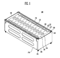
- FIG. 1 is a perspective view illustrating a battery module according to an embodiment.
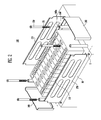
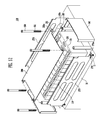
- FIG. 2 is an exploded perspective view illustrating the battery module shown in FIG. 1 .
- the battery module 100 may include a plurality of battery cells 110 arranged in one direction, in the embodiment shown in Fig. 1 in the x-direction.
- the battery cells 110 may be arranged such that wide surfaces of adjacent battery cells 110 face each other, i.e. the wide surfaces extend in a yz-plane.
- the battery cell 110 constituting the battery module 100 may include a battery case where one side is open and an electrode assembly and an electrolyte stored in the battery case.
- the electrode assembly and the electrolyte may generate energy in an electrochemical response.
- the battery case may be sealed by a first surface 118.
- the first surface 118 of the battery cell 110 may include a cap assembly and extends in a xy-plane.
- the first surface 118 may include a positive electrode terminal 112 and a negative electrode terminal 113, the positive and negative electrode terminals having different polarities, and a vent 114.
- the vent 114 serves as a passage through which gas generated inside the battery cell 110 is discharged to the outside as a safety tool of the battery cell 110.
- the battery cell 110 is a prismatic lithium ion secondary battery
- the present invention is not limited thereto and may be applied to various types of batteries including a lithium polymer battery.
- a pair of end plates 160 may be provided adjacent to the outermost battery cells 110.
- a pair of side plates 170 coupling the pair of end plates 160 may be provided on sides of the battery cells 110.
- the end plate 160 and the side plate 170 may be coupled to each other by means of the laser welding or ultrasonic wave welding.
- the plurality of battery cells 110 may be arranged in one direction in space sectioned by the pair of end plates 160 and the pair of side plates 170.
- the plurality of battery cells 110 may be arranged side by side such that the wide surfaces face each other and extend in a plane perpendicular to the stacking direction x.
- the positive electrode terminal 112 and the negative electrode terminal 113 of two adjacent battery cells 110 may be electrically connected to each other through a bus-bar 130.
- the bus-bar 130 may be formed of electro conductive metal such as gold, silver, copper, nickel, aluminum, copper alloy, aluminum alloy, etc. to electrically connect between the terminal portions 111.
- the bus-bar 130 may be coupled to the terminal portions 111 by means of welding.
- the welding may be the laser welding or the ultrasonic wave welding.
- the bus-bar 130 may take various forms based on a shape of the terminal portions 111.
- a bush member 140 may be coupled to the end plate 160.
- the bush member 140 may have a first hole 140a inside the bush member 140.
- the battery module 100 may be fastened to a base portion 10 of an apparatus where the battery module 100 is mounted by a fixing member 150 inserted into the bush member 140.
- FIG. 3 is a diagram illustrating a coupling relationship between an end plate, a bush member and a fixing member according to an embodiment.
- the end plate 160 may include extending portions 161 that are bent and extended at both ends from the first main portion 162 of the end plate 160 in a direction of the battery cell 110, i.e. in x-direction.
- the first main portion 162 in Fig. 3 has a plate like shape and extends in a plane perpendicular to the stacking direction x, i.e. in a yz plane.
- the bush member 140 may be coupled to the extending portion 161.
- the end plate 160 and the bush member 140 may be formed of metal like a material such as steel.
- the bush member 140 may be robustly coupled to the extending portion 161 by means of the laser welding or the ultrasonic wave welding.
- the first hole 140a that passes through along a direction of a length of the bush member 140 may be formed.
- the fixing member 150 may be inserted through the first hole 140a.
- the bush member 140 in the present invention has the shape of a bush, i.e. a tubular shape with a first hole 140a formed as a through hole in the middle of the bush member 140.
- the fixing member 150 may be a long bolt.
- the battery module 100 may be fixed to the base portion 10 by having a screw line 151 formed in a lower part of the fixing member 150 be fastened to a hole 11 formed at the base portion 10 of the apparatus.
- the battery module 100 is not fixed to the base portion 10 using a hole 11 passing through the base portion 10 and bolting the battery module 100 to the base portion 10 through the hole 11 by expanding the end plate; rather, the battery module 100 may be robustly fastened to the base portion 10 using a separate member such as the bush member 140.
- FIG. 4 is a perspective view illustrating an end plate and a bush member according to an embodiment.
- a guide portion 241 configured to guide a location of the bush member 240 at the extending portion 161 of the end plate 160.
- the bush member 240 may be guided such that the bush member 240 is positioned by the guide portion 241 to be where the bush member 240 is desired to be as the bush member 240 is hooked at a top of the end plate 160.
- the guide portion 241 is preferably formed at the top of the bush member 240. After fixation of the bush member 240, the guide portion 241 rests on the corner parts of the corner between the extending portion 161 and the first main portion 162.
- the guide portion 241 matches the configuration of the corner between the extending portion 161 and the first main portion 162 and thus the bush member 240 is guided into the corner portion by the matching shape of the guide portion 241 such that the bush member 240 is guided to its desired position at the end plate 160.
- the height of the bush member 240 including the guide portion 161 is preferably larger than the height of the end plate 160. Accordingly, the bush member 240 may be easily welded to the end plate 160.
- FIG. 5 is a perspective view illustrating an end plate and a bush member according to an embodiment.
- the end plate 260 may include first extending portions 261 that are bent and extended at both side ends of the end plate 260 in a direction of the battery cell 110, i.e. in the x-direction, and second extending portions 262 that are bent and extended at upper and lower ends of the first main portion 263 of the end plate 260 in a direction of the battery cell 110.
- the bush member 140 may be coupled to the second extending portion 262.
- FIG. 6 is a perspective view illustrating a battery module according to an embodiment.
- FIG. 7 is a perspective view illustrating the end block, end plate and bush member in FIG. 6 .
- the end block, end plate and bush member will be described.
- Like reference numerals refer to like elements throughout, and repetitive description will be omitted.
- the end block 180 may be provided between the outermost battery cell 110 and the end plate 160.
- the end block 180 may fill space, made by the bush member 140, between the end plate 160 and the battery cell 110.
- Mounting regions 181 where the bush members 140 are mounted may be provided at both ends of the end block 180.
- the mounting region 181 may correspond to the bush member 140 in shape.
- the mounting region 181 is mating the shape of the bush member 140.
- the mounting region 181 extends from the second main portion 182 of the end block 180.
- the end block 180 may be arranged to come in contact with the outermost battery cell 110 on the surface.
- the end block 180 may apply pressure to the plurality of battery cells 110 towards inside, which prevents a swelling phenomenon from occurring at the battery cells 110.
- pressure was applied to the battery cells 110 using only the end plates 160.
- the end block 180 is further included, which increases thickness of a portion applying pressure to the battery cells 110. Therefore, pressure may be more strongly applied to the battery cell 110.
- the end block 180 may be formed of a lighter material such as a plastic material, unlike the end plate 160 which is formed of a metal material. Accordingly, the end block 180 may not significantly increase the weight of the battery module 100.
- FIG. 8 is a perspective view illustrating the end block, end plate and bush member according to an embodiment.
- the end block, end plate and bush member will be described.
- Like reference numerals refer to like elements throughout, and repetitive description will be omitted.
- mounting regions 281 where the bush members 140 are mounted may be provided at upper and lower ends of the end block 280, respectively at the base portions 282 of the end block 280.
- the mounting region 281 may correspond to the bush member 140 in shape.
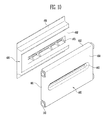
- FIG. 9 is a perspective view illustrating an end block 380 and an end plate 360 according to an embodiment.
- the end block and the end plate will be described.
- Like reference numerals refer to like elements throughout, and repetitive description will be omitted.
- the end plate 360 at the main portion 362 of the end plate 360, there may be formed at least a protruding region 363.
- the protruding region 363 may protrude in a direction of the end block 380.
- the main portion 382 of the end block 380 there may be formed at least a receiving region 383.
- the receiving region 383 may receive the protruding region 363. As the protruding region 363 is received by the receiving region 383, the end block 380 and the end plate 360 may be tightly coupled together, and hardness may be increased against bending of the end plate 360.
- FIG. 10 is a perspective view illustrating an end block and an end plate according to an embodiment.
- the end block and the end plate will be described.
- Like reference numerals refer to like elements throughout, and repetitive description will be omitted.
- the main portion 464 of the end plate 460 there may be formed at least a protruding region 463.
- the protruding region 463 may protrude in a direction of the end block 480.
- the main portion 482 of the end block 480 there may be formed at least a receiving region 483.
- the receiving region 483 may receive the protruding region 463. As the protruding region 463 is received by the receiving region 483, the end block 480 and the end plate 460 may be tightly coupled together, and hardness may be increased against bending of the end plate 460.
- the end plate 460 may include first extending portions 461 that are bent and extended at both side ends of the end plate 460 from the first main portion 464 in a direction of the battery cell 110, i.e. the x-direction, and second extending portions 462 that are bent and extended at upper and lower ends of the end plate 460 from the first main portion 464 in a direction of the battery cell 110.
- the bush member 140 may be coupled to the second extending portion 462.
- Mounting regions 481 where the bush members 140 are mounted may be provided at upper and lower ends of the end block 480.
- the mounting region 481 may correspond to the bush member 140 in shape.
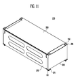
- FIG. 11 is a perspective view illustrating a battery module according to an embodiment.
- FIG. 12 is an exploded perspective view illustrating the battery module in FIG. 11 .
- the end block and the end plate will be described.
- Like reference numerals refer to like elements throughout, and repetitive description will be omitted.
- a side plate 270 may be arranged on a side of the battery cell 110.
- the side plate 270 may extend to a bottom of the bush member 140.
- the side plate 270 may include a first fixing hole portion 271 having a second hole 271 a inside.
- the fixing member 150 may be inserted into the first and second holes 140a and 271 a at the bush member 140, fastening the side plate 270 and the bush member 140 together. Therefore, the side plate 270 and the end plate 160 may be more robustly coupled.
- the battery module 100 may include a top plate 290 covering a top of the battery cell 110.
- the top plate 290 may cover a first side 118 of the battery cell 110.
- the first side 118 may be a side of the battery cell 110 where the terminal portions 222 are pulled out.
- the top plate 290 may be coupled to the side plate 270 by means of the ultrasonic wave welding or the laser welding.
- a second fixing hole portion 291 having a third hole 291 a inside may be provided at the top plate 290.
- the second fixing hole portion 291 may extend to the top of the bush member 140.
- the fixing member 150 may be inserted into the first and third holes 140a and 291 a at the bush member 140, fastening the top plate 290 and the bush member 140 together. Therefore, the top plate 290 and the end plate 160 may be more robustly coupled.
- the battery module 100 may separately include the bush member 140 in order to fix the battery module 100 to the base portion 10.
- the battery module 100 may be stably fixed.
- the bush members 140 are coupled to both ends or upper and lower ends of each of the pair of end plates, an impact coming from the outside that is applied to all across the battery module 100 may be uniformly distributed to the end plates, which prevents the impact from being applied to certain portions only.
Landscapes
- Chemical & Material Sciences (AREA)
- Chemical Kinetics & Catalysis (AREA)
- Electrochemistry (AREA)
- General Chemical & Material Sciences (AREA)
- Inorganic Chemistry (AREA)
- Battery Mounting, Suspending (AREA)
Abstract
Description
- An aspect of the present invention relates to a battery module.
- Recently, a high-power battery module using a non-aqueous electrolyte with high energy density has been developed. The high-power battery module is configured as a large-capacity battery module manufactured by connecting a plurality of battery cells in series so as to be used for driving devices, e.g., motors of electric vehicles and the like, which require high power.
- Typically, when the battery module is fixed to a base portion of an apparatus where the battery module is being mounted to, a hole for bolting is provided through expansion of an end plate adjacent to an outermost battery cell.
- However, the above method may induce an over design of a basic material of an end plate in order to secure hardness according to a weight of the battery module and an environment specification. In addition, a risk of concentration of stress due to localized module fixed structure may increase.
- Various embodiments provide a battery module.
- A battery module comprising a plurality of battery cells stacked along a first direction; a pair of end plates arranged spaced apart from each other in the first direction at respective end faces of the stacked battery cells; and at least one bush member is provided coupled to each end plate.
- By way of the bush members, the battery module can be stably fixed. Also, since the bush members are coupled to the end plates, an impact coming from the outside that is applied to the
battery module 100 may be uniformly distributed to the end plates, which prevents the impact from being applied to certain portions only. - The battery module may further comprise a fixing member, wherein the fixing member is fitted into the at least one bush member. Preferably, the fixing member is configured to fix the battery module to an external base plate. Advantageously, the fixing member together with the bush member allows an easy assembly and fixation of the battery module.
- The bush member is provided with a first hole extending along the length of the bush member through the bush member for receiving the fixing member. The configuration of the fixation element of the end plate, the bush member as a bush with a through hole allows simple fixation of the battery module.
- Each end plate extends in a plane perpendicular to the first direction. Each end plate comprises a first base portion and extending portions extending from the first base portion toward the battery cells, wherein the bush member is coupled to the extending portions. In this way, the bush member may be robustly coupled to the end plate.
- The bush member may further comprise a guide portion provided for positioning the bush member at the end plates. The guide portion is preferably formed at the top of the bush member and is provided on top of the end plate at a corner formed by the extending portion and the first base portion. Advantageously, the guide portion is configured to guide the bush member to its desired location at the end plate.
- The battery module in one embodiment further comprises an end block provided between an outermost battery cell of the stacked battery cells and the respective end plate. Advantageously, the end block fills a space between the outermost battery cell and the end plate.
- The end block provides a form fit with the respective end plate. Additionally or alternatively, the end block is formed of a material being lighter than the material of the respective end plate. Accordingly, the end block does not significantly increase the weight of the battery module. The end block may comprise a mounting region adapted to accommodate the bush member therein. The end block may further comprise a second base portion configured to closely contact the first base portion of the respective end plate. In this way, pressure can be applied to the outermost battery cell avoiding expansion of the battery cells.
- An end plate may comprise at least one protruding portion protruding into the direction of a respective end block and the end block may comprise at least one mating or corresponding receiving region for engaging with the protruding portion.
- A side plate may be provided on side surfaces of the stacked battery cells, the side plate includes a first fixing hole portion with a second hole provided to receive the fixing member extending through the bush member and provided to couple the side plate to the respective end plate.
- A covering plate is provided covering a first side of the stacked battery cells where terminal portions of the battery cells are located or at the opposite side of where terminal portions are located, and having a second fixing hole portion with a third hole provided at the location of the bush member to receive the fixing member and couple the top plate to the respective end plate. This allows a tight coupling of the end plate to the end block and hardness is consequently increased against bending of the end plate.
- Further provided is a system, preferably an electrical appliance system, which comprises a battery module according to the invention and an apparatus comprising a base portion for mounting the battery module to the apparatus, wherein the fixing member is fitted into the bush member of the battery module to couple the battery module to the base portion of the apparatus. In one embodiment, the apparatus may by an electrical apparatus using the energy provided by the inventive battery module. Advantageously, the fixing member together with the bush member allows simple and strong fixation of the battery module to the base plate.
- The fixing member in one embodiment is provided with a screw line and the base portion comprises a threaded hole for engaging with the screw line of the fixing member.
- The fixing member may be a long bolt.
- The accompanying drawings, together with the specification, illustrate exemplary embodiments of the present invention, and, together with the description, serve to explain the principles of the present invention.
-
FIG. 1 is a perspective view illustrating a battery module according to an embodiment. -
FIG. 2 is an exploded perspective view illustrating the battery module shown inFIG. 1 . -
FIG. 3 is a diagram illustrating a coupling relationship between an end plate, a bush member and a fixing member according to an embodiment. -
FIG. 4 is a perspective view illustrating an end plate and a bush member according to an embodiment. -
FIG. 5 is a perspective view illustrating an end plate and a bush member according to an embodiment. -
FIG. 6 is a perspective view illustrating a battery module according to an embodiment. -
FIG. 7 is a perspective view illustrating the end block, end plate and bush member inFIG. 6 . -
FIG. 8 is a perspective view illustrating the end block, end plate and bush member according to an embodiment. -
FIG. 9 is a perspective view illustrating an end block and an end plate according to an embodiment. -
FIG. 10 is a perspective view illustrating an end block and an end plate according to an embodiment. -
FIG. 11 is a perspective view illustrating a battery module according to an embodiment. -
FIG. 12 is an exploded perspective view illustrating the battery module inFIG. 11 . - In the following detailed description, only certain exemplary embodiments of the present invention have been shown and described, simply by way of illustration. Accordingly, the drawings and description are to be regarded as illustrative in nature and not restrictive. In addition, when an element is referred to as being "on" another element, it can be directly on the another element or be indirectly on the another element with one or more intervening elements interposed therebetween. Also, when an element is referred to as being "connected to" another element, it can be directly connected to the another element or be indirectly connected to the another element with one or more intervening elements interposed therebetween. Hereinafter, like reference numerals refer to like elements.
-
FIG. 1 is a perspective view illustrating a battery module according to an embodiment.FIG. 2 is an exploded perspective view illustrating the battery module shown inFIG. 1 . - In an embodiment, the
battery module 100 may include a plurality ofbattery cells 110 arranged in one direction, in the embodiment shown inFig. 1 in the x-direction. Thebattery cells 110 may be arranged such that wide surfaces ofadjacent battery cells 110 face each other, i.e. the wide surfaces extend in a yz-plane. - The
battery cell 110 constituting thebattery module 100 may include a battery case where one side is open and an electrode assembly and an electrolyte stored in the battery case. The electrode assembly and the electrolyte may generate energy in an electrochemical response. The battery case may be sealed by afirst surface 118. Thefirst surface 118 of thebattery cell 110 may include a cap assembly and extends in a xy-plane. Thefirst surface 118 may include apositive electrode terminal 112 and anegative electrode terminal 113, the positive and negative electrode terminals having different polarities, and avent 114. Thevent 114 serves as a passage through which gas generated inside thebattery cell 110 is discharged to the outside as a safety tool of thebattery cell 110. - In this embodiment, a case where the
battery cell 110 is a prismatic lithium ion secondary battery will be described as an example. However, the present invention is not limited thereto and may be applied to various types of batteries including a lithium polymer battery. - A pair of
end plates 160 may be provided adjacent to theoutermost battery cells 110. A pair ofside plates 170 coupling the pair ofend plates 160 may be provided on sides of thebattery cells 110. Theend plate 160 and theside plate 170 may be coupled to each other by means of the laser welding or ultrasonic wave welding. The plurality ofbattery cells 110 may be arranged in one direction in space sectioned by the pair ofend plates 160 and the pair ofside plates 170. - The plurality of
battery cells 110 may be arranged side by side such that the wide surfaces face each other and extend in a plane perpendicular to the stacking direction x. Thepositive electrode terminal 112 and thenegative electrode terminal 113 of twoadjacent battery cells 110 may be electrically connected to each other through a bus-bar 130. The bus-bar 130 may be formed of electro conductive metal such as gold, silver, copper, nickel, aluminum, copper alloy, aluminum alloy, etc. to electrically connect between theterminal portions 111. Furthermore, the bus-bar 130 may be coupled to theterminal portions 111 by means of welding. The welding may be the laser welding or the ultrasonic wave welding. The bus-bar 130 may take various forms based on a shape of theterminal portions 111. - A
bush member 140 may be coupled to theend plate 160. Thebush member 140 may have afirst hole 140a inside thebush member 140. Thebattery module 100 may be fastened to abase portion 10 of an apparatus where thebattery module 100 is mounted by a fixingmember 150 inserted into thebush member 140. -
FIG. 3 is a diagram illustrating a coupling relationship between an end plate, a bush member and a fixing member according to an embodiment. - Referring to
FIG. 3 , theend plate 160 may include extendingportions 161 that are bent and extended at both ends from the firstmain portion 162 of theend plate 160 in a direction of thebattery cell 110, i.e. in x-direction. The firstmain portion 162 inFig. 3 has a plate like shape and extends in a plane perpendicular to the stacking direction x, i.e. in a yz plane. Thebush member 140 may be coupled to the extendingportion 161. - The
end plate 160 and thebush member 140 may be formed of metal like a material such as steel. Thebush member 140 may be robustly coupled to the extendingportion 161 by means of the laser welding or the ultrasonic wave welding. - At the
bush member 140, thefirst hole 140a that passes through along a direction of a length of thebush member 140 may be formed. The fixingmember 150 may be inserted through thefirst hole 140a. Thebush member 140 in the present invention has the shape of a bush, i.e. a tubular shape with afirst hole 140a formed as a through hole in the middle of thebush member 140. - The fixing
member 150 may be a long bolt. Thebattery module 100 may be fixed to thebase portion 10 by having ascrew line 151 formed in a lower part of the fixingmember 150 be fastened to ahole 11 formed at thebase portion 10 of the apparatus. - In an embodiment, the
battery module 100 is not fixed to thebase portion 10 using ahole 11 passing through thebase portion 10 and bolting thebattery module 100 to thebase portion 10 through thehole 11 by expanding the end plate; rather, thebattery module 100 may be robustly fastened to thebase portion 10 using a separate member such as thebush member 140. -
FIG. 4 is a perspective view illustrating an end plate and a bush member according to an embodiment. - Referring to
FIG. 4 , on a top of thebush member 240, there may be formed aguide portion 241 configured to guide a location of thebush member 240 at the extendingportion 161 of theend plate 160. Thebush member 240 may be guided such that thebush member 240 is positioned by theguide portion 241 to be where thebush member 240 is desired to be as thebush member 240 is hooked at a top of theend plate 160. Theguide portion 241 is preferably formed at the top of thebush member 240. After fixation of thebush member 240, theguide portion 241 rests on the corner parts of the corner between the extendingportion 161 and the firstmain portion 162. Thus, theguide portion 241 matches the configuration of the corner between the extendingportion 161 and the firstmain portion 162 and thus thebush member 240 is guided into the corner portion by the matching shape of theguide portion 241 such that thebush member 240 is guided to its desired position at theend plate 160. The height of thebush member 240 including theguide portion 161 is preferably larger than the height of theend plate 160. Accordingly, thebush member 240 may be easily welded to theend plate 160. -
FIG. 5 is a perspective view illustrating an end plate and a bush member according to an embodiment. - Referring to
FIG. 5 , theend plate 260 may include first extendingportions 261 that are bent and extended at both side ends of theend plate 260 in a direction of thebattery cell 110, i.e. in the x-direction, and second extendingportions 262 that are bent and extended at upper and lower ends of the firstmain portion 263 of theend plate 260 in a direction of thebattery cell 110. Thebush member 140 may be coupled to the second extendingportion 262. -
FIG. 6 is a perspective view illustrating a battery module according to an embodiment.FIG. 7 is a perspective view illustrating the end block, end plate and bush member inFIG. 6 . In this embodiment, referring toFIGS. 6 and7 , the end block, end plate and bush member will be described. Like reference numerals refer to like elements throughout, and repetitive description will be omitted. - Referring to
FIGS. 6 and7 , theend block 180 may be provided between theoutermost battery cell 110 and theend plate 160. Theend block 180 may fill space, made by thebush member 140, between theend plate 160 and thebattery cell 110. Mountingregions 181 where thebush members 140 are mounted may be provided at both ends of theend block 180. The mountingregion 181 may correspond to thebush member 140 in shape. The mountingregion 181 is mating the shape of thebush member 140. The mountingregion 181 extends from the secondmain portion 182 of theend block 180. - The
end block 180 may be arranged to come in contact with theoutermost battery cell 110 on the surface. Theend block 180 may apply pressure to the plurality ofbattery cells 110 towards inside, which prevents a swelling phenomenon from occurring at thebattery cells 110. In a case of aconventional battery module 110, pressure was applied to thebattery cells 110 using only theend plates 160. In this case, since theend plates 160 were thin, and therefore, there was a limit to how strong of pressure may be applied to thebattery cells 110. However, in an embodiment, theend block 180 is further included, which increases thickness of a portion applying pressure to thebattery cells 110. Therefore, pressure may be more strongly applied to thebattery cell 110. - The
end block 180 may be formed of a lighter material such as a plastic material, unlike theend plate 160 which is formed of a metal material. Accordingly, theend block 180 may not significantly increase the weight of thebattery module 100. -
FIG. 8 is a perspective view illustrating the end block, end plate and bush member according to an embodiment. In this embodiment, referring toFIG. 8 , the end block, end plate and bush member will be described. Like reference numerals refer to like elements throughout, and repetitive description will be omitted. - Referring to
FIG. 8 , mountingregions 281 where thebush members 140 are mounted may be provided at upper and lower ends of theend block 280, respectively at thebase portions 282 of theend block 280. The mountingregion 281 may correspond to thebush member 140 in shape. -
FIG. 9 is a perspective view illustrating anend block 380 and anend plate 360 according to an embodiment. In this embodiment, referring toFIG. 9 , the end block and the end plate will be described. Like reference numerals refer to like elements throughout, and repetitive description will be omitted. - Referring to
FIG. 9 , on a side of theend plate 360, at themain portion 362 of theend plate 360, there may be formed at least aprotruding region 363. Theprotruding region 363 may protrude in a direction of theend block 380. On a side of theend block 380, themain portion 382 of theend block 380, there may be formed at least a receivingregion 383. The receivingregion 383 may receive theprotruding region 363. As theprotruding region 363 is received by the receivingregion 383, theend block 380 and theend plate 360 may be tightly coupled together, and hardness may be increased against bending of theend plate 360. -
FIG. 10 is a perspective view illustrating an end block and an end plate according to an embodiment. In this embodiment, referring toFIG. 10 , the end block and the end plate will be described. Like reference numerals refer to like elements throughout, and repetitive description will be omitted. - Referring to
FIG. 10 , on a side of theend plate 460, themain portion 464 of theend plate 460, there may be formed at least aprotruding region 463. Theprotruding region 463 may protrude in a direction of theend block 480. On a side of theend block 480, themain portion 482 of theend block 480, there may be formed at least a receivingregion 483. The receivingregion 483 may receive theprotruding region 463. As theprotruding region 463 is received by the receivingregion 483, theend block 480 and theend plate 460 may be tightly coupled together, and hardness may be increased against bending of theend plate 460. - The
end plate 460 may include first extendingportions 461 that are bent and extended at both side ends of theend plate 460 from the firstmain portion 464 in a direction of thebattery cell 110, i.e. the x-direction, and second extendingportions 462 that are bent and extended at upper and lower ends of theend plate 460 from the firstmain portion 464 in a direction of thebattery cell 110. Thebush member 140 may be coupled to the second extendingportion 462. - Mounting
regions 481 where thebush members 140 are mounted may be provided at upper and lower ends of theend block 480. The mountingregion 481 may correspond to thebush member 140 in shape. -
FIG. 11 is a perspective view illustrating a battery module according to an embodiment.FIG. 12 is an exploded perspective view illustrating the battery module inFIG. 11 . In this embodiment, referring toFIGS. 11 and12 , the end block and the end plate will be described. Like reference numerals refer to like elements throughout, and repetitive description will be omitted. - Referring to
FIGS. 11 and12 , aside plate 270 may be arranged on a side of thebattery cell 110. Theside plate 270 may extend to a bottom of thebush member 140. Theside plate 270 may include a firstfixing hole portion 271 having asecond hole 271 a inside. The fixingmember 150 may be inserted into the first andsecond holes bush member 140, fastening theside plate 270 and thebush member 140 together. Therefore, theside plate 270 and theend plate 160 may be more robustly coupled. - The
battery module 100 may include atop plate 290 covering a top of thebattery cell 110. Thetop plate 290 may cover afirst side 118 of thebattery cell 110. Thefirst side 118 may be a side of thebattery cell 110 where the terminal portions 222 are pulled out. As thetop plate 290 covers thefirst surface 118, short circuiting of theterminal portions 111 or the bus-bar 130 along with an outside conductive body may be prevented. Thetop plate 290 may be coupled to theside plate 270 by means of the ultrasonic wave welding or the laser welding. - At the
top plate 290, a secondfixing hole portion 291 having athird hole 291 a inside may be provided. The secondfixing hole portion 291 may extend to the top of thebush member 140. The fixingmember 150 may be inserted into the first andthird holes bush member 140, fastening thetop plate 290 and thebush member 140 together. Therefore, thetop plate 290 and theend plate 160 may be more robustly coupled. - By way of summation and review, the
battery module 100 may separately include thebush member 140 in order to fix thebattery module 100 to thebase portion 10. Thus, thebattery module 100 may be stably fixed. Also, since thebush members 140 are coupled to both ends or upper and lower ends of each of the pair of end plates, an impact coming from the outside that is applied to all across thebattery module 100 may be uniformly distributed to the end plates, which prevents the impact from being applied to certain portions only.
Claims (15)
- A battery module (100) comprising:a plurality of battery cells (110) stacked along a first direction;a pair of end plates (160) arranged spaced apart from each other in the first direction at respective end faces of the stacked battery cells (110);characterized in thatat least one bush member (140) is provided coupled to each end plate (160).
- The battery module (100) of claim 1, further comprising a fixing member (150), wherein the fixing member (150) is fitted into the at least one bush member (140).
- The battery module (100) of claim 2, wherein the bush member (140) is provided with a first hole (140a) extending along the length of the bush member (140) through the bush member (140) for receiving the fixing member (150).
- The battery module (100) of one of the previous claims, wherein each end plate (160) extends in a plane perpendicular to the first direction.
- The battery module (100) of one of the previous claims, wherein each end plate (160) comprises a first main portion (162) and extending portions (161) extending from the first main portion (162) toward the battery cells (110), wherein the bush member (140) is coupled to the extending portions (161).
- The battery module (100) of one of the previous claims, wherein the bush member (240) further comprises a guide portion (241):provided for positioning the bush member (240) at the end plates (160), and/orformed at the top of the bush member (240) and is provided on top of the end plate (160) at a corner formed by the extending portion (161) and the first main portion (162).
- The battery module (100) of one of the previous claims, further comprising an end block (180) provided between an outermost battery cell (110) of the stacked battery cells (110) and the respective end plate (160).
- The battery module (100) of claim 7, wherein the end block (180):provides a form fit with the respective end plate (160), and/oris formed of a material being lighter than the material of the respective end plate (160).
- The battery module (100) of claim 7 or 8, wherein the end block (180) comprises a mounting region (181) adapted to accommodate the bush member (140) therein.
- The battery module (100) of claim 9, wherein the end block (180) further comprises a second main portion (182) configured to closely contact the first main portion (162) of the respective end plate (160).
- The battery module (100) of one of the previous claims 7 to 10, wherein an end plate (360) comprises at least one protruding portion (363) protruding into the direction of a respective end block (380) and the end block (380) comprises at least one mating receiving region (383) for engaging with the protruding portion (363).
- The battery module (100) of one of the previous claims 2 to 11, wherein a side plate (270) is provided on side surfaces of the stacked battery cells (110), the side plate (270) includes a first fixing hole portion (271) with a second hole (271 a) provided to receive the fixing member (150) extending through the bush member (140) and provided to couple the side plate (270) to the respective end plate (140).
- The battery module (100) of one of the previous claims 2 to 12, wherein a top plate (290) is provided covering a first side (118) of the stacked battery cells (110) where terminal portions (112) of the battery cells (110) are located or at the opposite side of where terminal portions (112) are located, and having a second fixing hole portion (291) with a third hole (291 a) provided at the location of the bush member (140) to receive the fixing member (150) and couple the top plate (290) to the respective end plate (140).
- A system comprising:a battery module (100) according to one of the previous claims 2 to 13, andan apparatus comprising a base portion (10) for mounting the battery module (100) to the apparatus,wherein the fixing member (150) fitted into the bush member (140) of the battery module (100) is coupled to the base portion (10).
- The system of claim 14, wherein the fixing member (150) is provided with a screw line (151) and the base portion (10) comprises a threaded hole (11) for engaging with the screw line of the fixing member (150).
Applications Claiming Priority (2)
| Application Number | Priority Date | Filing Date | Title |
|---|---|---|---|
| US201361839965P | 2013-06-27 | 2013-06-27 | |
| US14/245,586 US9537125B2 (en) | 2013-06-27 | 2014-04-04 | Battery module |
Publications (2)
| Publication Number | Publication Date |
|---|---|
| EP2819210A1 true EP2819210A1 (en) | 2014-12-31 |
| EP2819210B1 EP2819210B1 (en) | 2017-10-18 |
Family
ID=50942180
Family Applications (1)
| Application Number | Title | Priority Date | Filing Date |
|---|---|---|---|
| EP14172642.2A Active EP2819210B1 (en) | 2013-06-27 | 2014-06-17 | Battery module |
Country Status (5)
| Country | Link |
|---|---|
| US (1) | US9537125B2 (en) |
| EP (1) | EP2819210B1 (en) |
| JP (1) | JP6393086B2 (en) |
| KR (1) | KR102222887B1 (en) |
| CN (1) | CN104253252B (en) |
Cited By (13)
| Publication number | Priority date | Publication date | Assignee | Title |
|---|---|---|---|---|
| EP2874201A1 (en) * | 2013-11-19 | 2015-05-20 | Samsung SDI Co., Ltd. | Battery Module |
| DE102014223047A1 (en) * | 2014-11-12 | 2016-05-12 | Robert Bosch Gmbh | Receptacle for a battery module and battery module having such a receptacle |
| EP3026730A4 (en) * | 2013-07-26 | 2017-03-22 | Nippon Steel & Sumitomo Metal Corporation | Assembled battery stacker and assembled battery |
| EP3168898A1 (en) * | 2015-11-16 | 2017-05-17 | Samsung SDI Co., Ltd. | Rechargeable battery module |
| EP3270439A1 (en) * | 2016-07-13 | 2018-01-17 | Contemporary Amperex Technology Co., Limited | Battery module |
| EP3300137A1 (en) * | 2016-09-23 | 2018-03-28 | Contemporary Amperex Technology Co., Limited | Battery module |
| EP3343667A1 (en) * | 2016-12-27 | 2018-07-04 | Contemporary Amperex Technology Co., Limited | End plate of battery module and battery module |
| EP3496182A1 (en) * | 2017-12-11 | 2019-06-12 | Samsung SDI Co., Ltd. | Battery pack |
| EP3506387A1 (en) * | 2017-12-29 | 2019-07-03 | Contemporary Amperex Technology Co., Limited | Composite end plate and battery module |
| DE102018127308A1 (en) * | 2018-10-31 | 2020-04-30 | Kautex Textron Gmbh & Co. Kg | Plate element for a battery module and battery module |
| CN112673517A (en) * | 2018-09-14 | 2021-04-16 | 三洋电机株式会社 | Battery system, vehicle with battery system, and power storage device |
| EP3832750A4 (en) * | 2018-07-31 | 2021-08-25 | SANYO Electric Co., Ltd. | Power supply device and vehicle equipped with same |
| US11626641B2 (en) | 2019-04-18 | 2023-04-11 | Contemporary Amperex Technology Co., Limited | Battery module |
Families Citing this family (25)
| Publication number | Priority date | Publication date | Assignee | Title |
|---|---|---|---|---|
| US10566587B2 (en) * | 2015-04-14 | 2020-02-18 | Ford Global Technologies, Llc | Electrified vehicle plate with integrated compression limiter |
| KR101939832B1 (en) * | 2015-09-23 | 2019-01-17 | 주식회사 엘지화학 | Battery module and battery pack including the same and method for manufacturing a battery module casing |
| JP6743359B2 (en) * | 2015-09-29 | 2020-08-19 | 株式会社Gsユアサ | Power storage device |
| US11050107B2 (en) | 2015-10-22 | 2021-06-29 | Envision Aesc Japan Ltd. | Method for assembling battery pack, and battery pack |
| US10985420B2 (en) * | 2016-01-22 | 2021-04-20 | Ford Global Technologies, Llc | Battery pack with slide-in battery assembly |
| CN105742539B (en) * | 2016-04-21 | 2019-04-05 | 宁德时代新能源科技股份有限公司 | Electricity core module |
| US11011790B2 (en) * | 2017-03-17 | 2021-05-18 | Ford Global Technologies, Llc | Traction battery pack plate with retention flange |
| JP6686948B2 (en) * | 2017-03-23 | 2020-04-22 | トヨタ自動車株式会社 | Vehicle substructure |
| CN108735926B (en) * | 2017-04-20 | 2021-09-21 | 宁德时代新能源科技股份有限公司 | Battery module |
| CN107046115A (en) * | 2017-05-02 | 2017-08-15 | 江苏银基烯碳能源科技有限公司 | A kind of battery modules |
| JP7150725B2 (en) * | 2017-07-27 | 2022-10-11 | 三洋電機株式会社 | Battery module and vehicle equipped with it |
| CN208014772U (en) * | 2018-03-16 | 2018-10-26 | 宁德时代新能源科技股份有限公司 | End plate, shell and battery modules |
| US11817593B2 (en) | 2018-03-30 | 2023-11-14 | Sanyo Electric Co., Ltd. | Power supply device and vehicle provided with power supply device |
| JP7033255B2 (en) * | 2018-05-02 | 2022-03-10 | トヨタ自動車株式会社 | Batteries assembled |
| JP7027255B2 (en) * | 2018-05-31 | 2022-03-01 | 本田技研工業株式会社 | Battery pack |
| WO2019235173A1 (en) * | 2018-06-05 | 2019-12-12 | 三洋電機株式会社 | Battery module and vehicle equipped with same |
| US11724604B2 (en) * | 2018-06-25 | 2023-08-15 | Ford Global Technologies, Llc | Split panel array plate assemblies for electrified vehicle battery packs |
| JP7151473B2 (en) * | 2018-12-27 | 2022-10-12 | トヨタ自動車株式会社 | storage module |
| DE102019205777A1 (en) | 2019-04-23 | 2020-10-29 | Audi Ag | Clamping device for a battery module, battery module and motor vehicle |
| KR102398574B1 (en) * | 2019-10-10 | 2022-05-13 | 주식회사 엘지에너지솔루션 | Battery module and battery pack including the same |
| KR20210126306A (en) | 2020-04-10 | 2021-10-20 | 주식회사 엘지에너지솔루션 | Battery module and battery pack including the same |
| CN114361684A (en) * | 2020-09-27 | 2022-04-15 | 比亚迪股份有限公司 | Battery tray and battery pack with same |
| KR102677972B1 (en) * | 2023-11-22 | 2024-06-25 | 신성에스티 주식회사 | End Plate for Battery Module |
| KR102647909B1 (en) * | 2023-11-22 | 2024-03-15 | 신성에스티 주식회사 | End Plate for Battery Module |
| KR102672157B1 (en) * | 2023-11-22 | 2024-06-05 | 신성에스티 주식회사 | End Plate for Battery Module |
Citations (6)
| Publication number | Priority date | Publication date | Assignee | Title |
|---|---|---|---|---|
| US20110117409A1 (en) * | 2009-11-16 | 2011-05-19 | Hyun-Ye Lee | Battery module having improved end plate |
| US20110151299A1 (en) * | 2009-12-18 | 2011-06-23 | Shi-Dong Park | Battery module and method of manufacturing the battery module |
| US20120315508A1 (en) * | 2011-06-08 | 2012-12-13 | Honda Motor Co., Ltd | Battery module |
| WO2013073046A1 (en) * | 2011-11-18 | 2013-05-23 | 日立ビークルエナジー株式会社 | Secondary cell module |
| DE102011120247A1 (en) * | 2011-12-05 | 2013-06-06 | Audi Ag | Battery for vehicle, has fixing units that are connected with battery modules through structural elements of end plates of cell stack such that fixing units are aligned with each other in battery main portion |
| US20130149577A1 (en) * | 2010-08-16 | 2013-06-13 | Lg Chem, Ltd. | Battery module and battery pack employed with the same |
Family Cites Families (4)
| Publication number | Priority date | Publication date | Assignee | Title |
|---|---|---|---|---|
| US4317497A (en) * | 1980-07-28 | 1982-03-02 | General Motors Corporation | Battery tray for electric vehicle |
| JP2006236826A (en) * | 2005-02-25 | 2006-09-07 | Toyota Motor Corp | Battery pack |
| PL2266154T3 (en) * | 2008-04-14 | 2015-11-30 | A123 Systems Llc | Flexible voltage nested battery module design |
| WO2012043594A1 (en) * | 2010-09-30 | 2012-04-05 | 三洋電機株式会社 | Assembled battery and vehicle provided with same |
-
2014
- 2014-04-04 US US14/245,586 patent/US9537125B2/en active Active
- 2014-04-08 KR KR1020140041660A patent/KR102222887B1/en active IP Right Grant
- 2014-05-30 CN CN201410240880.XA patent/CN104253252B/en active Active
- 2014-06-05 JP JP2014116577A patent/JP6393086B2/en active Active
- 2014-06-17 EP EP14172642.2A patent/EP2819210B1/en active Active
Patent Citations (6)
| Publication number | Priority date | Publication date | Assignee | Title |
|---|---|---|---|---|
| US20110117409A1 (en) * | 2009-11-16 | 2011-05-19 | Hyun-Ye Lee | Battery module having improved end plate |
| US20110151299A1 (en) * | 2009-12-18 | 2011-06-23 | Shi-Dong Park | Battery module and method of manufacturing the battery module |
| US20130149577A1 (en) * | 2010-08-16 | 2013-06-13 | Lg Chem, Ltd. | Battery module and battery pack employed with the same |
| US20120315508A1 (en) * | 2011-06-08 | 2012-12-13 | Honda Motor Co., Ltd | Battery module |
| WO2013073046A1 (en) * | 2011-11-18 | 2013-05-23 | 日立ビークルエナジー株式会社 | Secondary cell module |
| DE102011120247A1 (en) * | 2011-12-05 | 2013-06-06 | Audi Ag | Battery for vehicle, has fixing units that are connected with battery modules through structural elements of end plates of cell stack such that fixing units are aligned with each other in battery main portion |
Cited By (23)
| Publication number | Priority date | Publication date | Assignee | Title |
|---|---|---|---|---|
| EP3026730A4 (en) * | 2013-07-26 | 2017-03-22 | Nippon Steel & Sumitomo Metal Corporation | Assembled battery stacker and assembled battery |
| US10199617B2 (en) | 2013-07-26 | 2019-02-05 | Nippon Steel & Sumitomo Metal Corporation | Assembled-battery stacker and assembled battery |
| EP2874201A1 (en) * | 2013-11-19 | 2015-05-20 | Samsung SDI Co., Ltd. | Battery Module |
| US9748539B2 (en) | 2013-11-19 | 2017-08-29 | Samsung Sdi Co., Ltd. | Battery module |
| DE102014223047A1 (en) * | 2014-11-12 | 2016-05-12 | Robert Bosch Gmbh | Receptacle for a battery module and battery module having such a receptacle |
| US10461382B2 (en) | 2014-11-12 | 2019-10-29 | Robert Bosch Gmbh | Receptacle for a battery module and battery module having such a receptacle |
| EP3168898A1 (en) * | 2015-11-16 | 2017-05-17 | Samsung SDI Co., Ltd. | Rechargeable battery module |
| US10439179B2 (en) | 2015-11-16 | 2019-10-08 | Samsung Sdi Co., Ltd. | Rechargeable battery module including welding bushes |
| EP3270439A1 (en) * | 2016-07-13 | 2018-01-17 | Contemporary Amperex Technology Co., Limited | Battery module |
| EP3300137A1 (en) * | 2016-09-23 | 2018-03-28 | Contemporary Amperex Technology Co., Limited | Battery module |
| US10490786B2 (en) | 2016-09-23 | 2019-11-26 | Contemporary Amperex Technology Co., Limited | Battery module |
| EP3343667A1 (en) * | 2016-12-27 | 2018-07-04 | Contemporary Amperex Technology Co., Limited | End plate of battery module and battery module |
| US10581042B2 (en) | 2016-12-27 | 2020-03-03 | Contemporary Amperex Technology Co., Limited | End plate of battery module and battery module |
| EP3496182A1 (en) * | 2017-12-11 | 2019-06-12 | Samsung SDI Co., Ltd. | Battery pack |
| US11031648B2 (en) | 2017-12-11 | 2021-06-08 | Samsung Sdi Co., Ltd. | Battery pack |
| EP3506387A1 (en) * | 2017-12-29 | 2019-07-03 | Contemporary Amperex Technology Co., Limited | Composite end plate and battery module |
| US10944141B2 (en) | 2017-12-29 | 2021-03-09 | Contemporary Amperex Technology Co., Limited | Composite end plate and battery module |
| EP3832750A4 (en) * | 2018-07-31 | 2021-08-25 | SANYO Electric Co., Ltd. | Power supply device and vehicle equipped with same |
| CN112673517A (en) * | 2018-09-14 | 2021-04-16 | 三洋电机株式会社 | Battery system, vehicle with battery system, and power storage device |
| CN112673517B (en) * | 2018-09-14 | 2022-11-04 | 三洋电机株式会社 | Battery system, vehicle with battery system, and power storage device |
| DE102018127308A1 (en) * | 2018-10-31 | 2020-04-30 | Kautex Textron Gmbh & Co. Kg | Plate element for a battery module and battery module |
| US11626641B2 (en) | 2019-04-18 | 2023-04-11 | Contemporary Amperex Technology Co., Limited | Battery module |
| US12080902B2 (en) | 2019-04-18 | 2024-09-03 | Contemporary Amperex Technology Co., Limited | Battery module |
Also Published As
| Publication number | Publication date |
|---|---|
| CN104253252B (en) | 2018-12-04 |
| KR102222887B1 (en) | 2021-03-04 |
| US9537125B2 (en) | 2017-01-03 |
| EP2819210B1 (en) | 2017-10-18 |
| KR20150001604A (en) | 2015-01-06 |
| US20150004469A1 (en) | 2015-01-01 |
| CN104253252A (en) | 2014-12-31 |
| JP6393086B2 (en) | 2018-09-19 |
| JP2015011989A (en) | 2015-01-19 |
Similar Documents
| Publication | Publication Date | Title |
|---|---|---|
| EP2819210B1 (en) | Battery module | |
| KR101688489B1 (en) | Battery module | |
| US9318734B2 (en) | Bimetal buss bar assembly | |
| US11289776B2 (en) | Battery module having bus bar assembly | |
| US10629882B2 (en) | Battery module | |
| EP2808927A1 (en) | Battery module | |
| US11450930B2 (en) | Battery module and battery pack having same | |
| KR101888214B1 (en) | Power storage device | |
| EP2843731A2 (en) | Battery module | |
| EP3490034B1 (en) | Electrode member, electrode assembly and rechargeable battery | |
| US20150171404A1 (en) | Battery module | |
| US9627674B2 (en) | Battery module | |
| US12087972B2 (en) | Sealed battery | |
| US9831486B2 (en) | Battery module | |
| JP7174345B2 (en) | power storage device | |
| US20220037746A1 (en) | Secondary battery | |
| US9034513B2 (en) | Energy storage device | |
| CN111868958B (en) | Battery pack | |
| KR101802347B1 (en) | Rectangular Type Secondary Battery Comprising Arcuate-shaped Top Cap and Method for Preparing the Same |
Legal Events
| Date | Code | Title | Description |
|---|---|---|---|
| PUAI | Public reference made under article 153(3) epc to a published international application that has entered the european phase |
Free format text: ORIGINAL CODE: 0009012 |
|
| 17P | Request for examination filed |
Effective date: 20140617 |
|
| AK | Designated contracting states |
Kind code of ref document: A1 Designated state(s): AL AT BE BG CH CY CZ DE DK EE ES FI FR GB GR HR HU IE IS IT LI LT LU LV MC MK MT NL NO PL PT RO RS SE SI SK SM TR |
|
| AX | Request for extension of the european patent |
Extension state: BA ME |
|
| R17P | Request for examination filed (corrected) |
Effective date: 20150630 |
|
| RBV | Designated contracting states (corrected) |
Designated state(s): AL AT BE BG CH CY CZ DE DK EE ES FI FR GB GR HR HU IE IS IT LI LT LU LV MC MK MT NL NO PL PT RO RS SE SI SK SM TR |
|
| 17Q | First examination report despatched |
Effective date: 20160519 |
|
| GRAP | Despatch of communication of intention to grant a patent |
Free format text: ORIGINAL CODE: EPIDOSNIGR1 |
|
| INTG | Intention to grant announced |
Effective date: 20170607 |
|
| GRAS | Grant fee paid |
Free format text: ORIGINAL CODE: EPIDOSNIGR3 |
|
| GRAA | (expected) grant |
Free format text: ORIGINAL CODE: 0009210 |
|
| AK | Designated contracting states |
Kind code of ref document: B1 Designated state(s): AL AT BE BG CH CY CZ DE DK EE ES FI FR GB GR HR HU IE IS IT LI LT LU LV MC MK MT NL NO PL PT RO RS SE SI SK SM TR |
|
| REG | Reference to a national code |
Ref country code: GB Ref legal event code: FG4D |
|
| REG | Reference to a national code |
Ref country code: CH Ref legal event code: EP |
|
| REG | Reference to a national code |
Ref country code: AT Ref legal event code: REF Ref document number: 938660 Country of ref document: AT Kind code of ref document: T Effective date: 20171115 Ref country code: IE Ref legal event code: FG4D |
|
| REG | Reference to a national code |
Ref country code: DE Ref legal event code: R096 Ref document number: 602014015877 Country of ref document: DE |
|
| REG | Reference to a national code |
Ref country code: NL Ref legal event code: MP Effective date: 20171018 |
|
| REG | Reference to a national code |
Ref country code: LT Ref legal event code: MG4D |
|
| REG | Reference to a national code |
Ref country code: AT Ref legal event code: MK05 Ref document number: 938660 Country of ref document: AT Kind code of ref document: T Effective date: 20171018 |
|
| PG25 | Lapsed in a contracting state [announced via postgrant information from national office to epo] |
Ref country code: NL Free format text: LAPSE BECAUSE OF FAILURE TO SUBMIT A TRANSLATION OF THE DESCRIPTION OR TO PAY THE FEE WITHIN THE PRESCRIBED TIME-LIMIT Effective date: 20171018 |
|
| PG25 | Lapsed in a contracting state [announced via postgrant information from national office to epo] |
Ref country code: LT Free format text: LAPSE BECAUSE OF FAILURE TO SUBMIT A TRANSLATION OF THE DESCRIPTION OR TO PAY THE FEE WITHIN THE PRESCRIBED TIME-LIMIT Effective date: 20171018 Ref country code: NO Free format text: LAPSE BECAUSE OF FAILURE TO SUBMIT A TRANSLATION OF THE DESCRIPTION OR TO PAY THE FEE WITHIN THE PRESCRIBED TIME-LIMIT Effective date: 20180118 Ref country code: FI Free format text: LAPSE BECAUSE OF FAILURE TO SUBMIT A TRANSLATION OF THE DESCRIPTION OR TO PAY THE FEE WITHIN THE PRESCRIBED TIME-LIMIT Effective date: 20171018 Ref country code: SE Free format text: LAPSE BECAUSE OF FAILURE TO SUBMIT A TRANSLATION OF THE DESCRIPTION OR TO PAY THE FEE WITHIN THE PRESCRIBED TIME-LIMIT Effective date: 20171018 Ref country code: ES Free format text: LAPSE BECAUSE OF FAILURE TO SUBMIT A TRANSLATION OF THE DESCRIPTION OR TO PAY THE FEE WITHIN THE PRESCRIBED TIME-LIMIT Effective date: 20171018 |
|
| REG | Reference to a national code |
Ref country code: FR Ref legal event code: PLFP Year of fee payment: 5 |
|
| PG25 | Lapsed in a contracting state [announced via postgrant information from national office to epo] |
Ref country code: RS Free format text: LAPSE BECAUSE OF FAILURE TO SUBMIT A TRANSLATION OF THE DESCRIPTION OR TO PAY THE FEE WITHIN THE PRESCRIBED TIME-LIMIT Effective date: 20171018 Ref country code: AT Free format text: LAPSE BECAUSE OF FAILURE TO SUBMIT A TRANSLATION OF THE DESCRIPTION OR TO PAY THE FEE WITHIN THE PRESCRIBED TIME-LIMIT Effective date: 20171018 Ref country code: IS Free format text: LAPSE BECAUSE OF FAILURE TO SUBMIT A TRANSLATION OF THE DESCRIPTION OR TO PAY THE FEE WITHIN THE PRESCRIBED TIME-LIMIT Effective date: 20180218 Ref country code: LV Free format text: LAPSE BECAUSE OF FAILURE TO SUBMIT A TRANSLATION OF THE DESCRIPTION OR TO PAY THE FEE WITHIN THE PRESCRIBED TIME-LIMIT Effective date: 20171018 Ref country code: HR Free format text: LAPSE BECAUSE OF FAILURE TO SUBMIT A TRANSLATION OF THE DESCRIPTION OR TO PAY THE FEE WITHIN THE PRESCRIBED TIME-LIMIT Effective date: 20171018 Ref country code: BG Free format text: LAPSE BECAUSE OF FAILURE TO SUBMIT A TRANSLATION OF THE DESCRIPTION OR TO PAY THE FEE WITHIN THE PRESCRIBED TIME-LIMIT Effective date: 20180118 Ref country code: GR Free format text: LAPSE BECAUSE OF FAILURE TO SUBMIT A TRANSLATION OF THE DESCRIPTION OR TO PAY THE FEE WITHIN THE PRESCRIBED TIME-LIMIT Effective date: 20180119 |
|
| REG | Reference to a national code |
Ref country code: DE Ref legal event code: R097 Ref document number: 602014015877 Country of ref document: DE |
|
| PG25 | Lapsed in a contracting state [announced via postgrant information from national office to epo] |
Ref country code: CZ Free format text: LAPSE BECAUSE OF FAILURE TO SUBMIT A TRANSLATION OF THE DESCRIPTION OR TO PAY THE FEE WITHIN THE PRESCRIBED TIME-LIMIT Effective date: 20171018 Ref country code: SK Free format text: LAPSE BECAUSE OF FAILURE TO SUBMIT A TRANSLATION OF THE DESCRIPTION OR TO PAY THE FEE WITHIN THE PRESCRIBED TIME-LIMIT Effective date: 20171018 Ref country code: DK Free format text: LAPSE BECAUSE OF FAILURE TO SUBMIT A TRANSLATION OF THE DESCRIPTION OR TO PAY THE FEE WITHIN THE PRESCRIBED TIME-LIMIT Effective date: 20171018 Ref country code: EE Free format text: LAPSE BECAUSE OF FAILURE TO SUBMIT A TRANSLATION OF THE DESCRIPTION OR TO PAY THE FEE WITHIN THE PRESCRIBED TIME-LIMIT Effective date: 20171018 |
|
| PLBE | No opposition filed within time limit |
Free format text: ORIGINAL CODE: 0009261 |
|
| STAA | Information on the status of an ep patent application or granted ep patent |
Free format text: STATUS: NO OPPOSITION FILED WITHIN TIME LIMIT |
|
| PG25 | Lapsed in a contracting state [announced via postgrant information from national office to epo] |
Ref country code: RO Free format text: LAPSE BECAUSE OF FAILURE TO SUBMIT A TRANSLATION OF THE DESCRIPTION OR TO PAY THE FEE WITHIN THE PRESCRIBED TIME-LIMIT Effective date: 20171018 Ref country code: IT Free format text: LAPSE BECAUSE OF FAILURE TO SUBMIT A TRANSLATION OF THE DESCRIPTION OR TO PAY THE FEE WITHIN THE PRESCRIBED TIME-LIMIT Effective date: 20171018 Ref country code: SM Free format text: LAPSE BECAUSE OF FAILURE TO SUBMIT A TRANSLATION OF THE DESCRIPTION OR TO PAY THE FEE WITHIN THE PRESCRIBED TIME-LIMIT Effective date: 20171018 Ref country code: PL Free format text: LAPSE BECAUSE OF FAILURE TO SUBMIT A TRANSLATION OF THE DESCRIPTION OR TO PAY THE FEE WITHIN THE PRESCRIBED TIME-LIMIT Effective date: 20171018 |
|
| 26N | No opposition filed |
Effective date: 20180719 |
|
| PG25 | Lapsed in a contracting state [announced via postgrant information from national office to epo] |
Ref country code: SI Free format text: LAPSE BECAUSE OF FAILURE TO SUBMIT A TRANSLATION OF THE DESCRIPTION OR TO PAY THE FEE WITHIN THE PRESCRIBED TIME-LIMIT Effective date: 20171018 |
|
| REG | Reference to a national code |
Ref country code: CH Ref legal event code: PL |
|
| REG | Reference to a national code |
Ref country code: BE Ref legal event code: MM Effective date: 20180630 |
|
| REG | Reference to a national code |
Ref country code: IE Ref legal event code: MM4A |
|
| PG25 | Lapsed in a contracting state [announced via postgrant information from national office to epo] |
Ref country code: MC Free format text: LAPSE BECAUSE OF FAILURE TO SUBMIT A TRANSLATION OF THE DESCRIPTION OR TO PAY THE FEE WITHIN THE PRESCRIBED TIME-LIMIT Effective date: 20171018 Ref country code: LU Free format text: LAPSE BECAUSE OF NON-PAYMENT OF DUE FEES Effective date: 20180617 |
|
| PG25 | Lapsed in a contracting state [announced via postgrant information from national office to epo] |
Ref country code: CH Free format text: LAPSE BECAUSE OF NON-PAYMENT OF DUE FEES Effective date: 20180630 Ref country code: LI Free format text: LAPSE BECAUSE OF NON-PAYMENT OF DUE FEES Effective date: 20180630 Ref country code: IE Free format text: LAPSE BECAUSE OF NON-PAYMENT OF DUE FEES Effective date: 20180617 |
|
| PG25 | Lapsed in a contracting state [announced via postgrant information from national office to epo] |
Ref country code: BE Free format text: LAPSE BECAUSE OF NON-PAYMENT OF DUE FEES Effective date: 20180630 |
|
| PG25 | Lapsed in a contracting state [announced via postgrant information from national office to epo] |
Ref country code: MT Free format text: LAPSE BECAUSE OF NON-PAYMENT OF DUE FEES Effective date: 20180617 |
|
| PG25 | Lapsed in a contracting state [announced via postgrant information from national office to epo] |
Ref country code: TR Free format text: LAPSE BECAUSE OF FAILURE TO SUBMIT A TRANSLATION OF THE DESCRIPTION OR TO PAY THE FEE WITHIN THE PRESCRIBED TIME-LIMIT Effective date: 20171018 |
|
| PG25 | Lapsed in a contracting state [announced via postgrant information from national office to epo] |
Ref country code: HU Free format text: LAPSE BECAUSE OF FAILURE TO SUBMIT A TRANSLATION OF THE DESCRIPTION OR TO PAY THE FEE WITHIN THE PRESCRIBED TIME-LIMIT; INVALID AB INITIO Effective date: 20140617 Ref country code: PT Free format text: LAPSE BECAUSE OF FAILURE TO SUBMIT A TRANSLATION OF THE DESCRIPTION OR TO PAY THE FEE WITHIN THE PRESCRIBED TIME-LIMIT Effective date: 20171018 |
|
| PG25 | Lapsed in a contracting state [announced via postgrant information from national office to epo] |
Ref country code: MK Free format text: LAPSE BECAUSE OF NON-PAYMENT OF DUE FEES Effective date: 20171018 Ref country code: CY Free format text: LAPSE BECAUSE OF FAILURE TO SUBMIT A TRANSLATION OF THE DESCRIPTION OR TO PAY THE FEE WITHIN THE PRESCRIBED TIME-LIMIT Effective date: 20171018 |
|
| PG25 | Lapsed in a contracting state [announced via postgrant information from national office to epo] |
Ref country code: AL Free format text: LAPSE BECAUSE OF FAILURE TO SUBMIT A TRANSLATION OF THE DESCRIPTION OR TO PAY THE FEE WITHIN THE PRESCRIBED TIME-LIMIT Effective date: 20171018 |
|
| REG | Reference to a national code |
Ref country code: DE Ref legal event code: R079 Ref document number: 602014015877 Country of ref document: DE Free format text: PREVIOUS MAIN CLASS: H01M0002100000 Ipc: H01M0050200000 |
|
| P01 | Opt-out of the competence of the unified patent court (upc) registered |
Effective date: 20230528 |
|
| PGFP | Annual fee paid to national office [announced via postgrant information from national office to epo] |
Ref country code: GB Payment date: 20240530 Year of fee payment: 11 |
|
| PGFP | Annual fee paid to national office [announced via postgrant information from national office to epo] |
Ref country code: DE Payment date: 20240604 Year of fee payment: 11 |
|
| PGFP | Annual fee paid to national office [announced via postgrant information from national office to epo] |
Ref country code: FR Payment date: 20240611 Year of fee payment: 11 |