EP2819131B1 - Inductor layout for reduced VCO coupling - Google Patents
Inductor layout for reduced VCO coupling Download PDFInfo
- Publication number
- EP2819131B1 EP2819131B1 EP14172888.1A EP14172888A EP2819131B1 EP 2819131 B1 EP2819131 B1 EP 2819131B1 EP 14172888 A EP14172888 A EP 14172888A EP 2819131 B1 EP2819131 B1 EP 2819131B1
- Authority
- EP
- European Patent Office
- Prior art keywords
- inductor
- semiconductor die
- loop
- inductors
- shaped
- Prior art date
- Legal status (The legal status is an assumption and is not a legal conclusion. Google has not performed a legal analysis and makes no representation as to the accuracy of the status listed.)
- Expired - Lifetime
Links
Images


Classifications
-
- H—ELECTRICITY
- H01—ELECTRIC ELEMENTS
- H01F—MAGNETS; INDUCTANCES; TRANSFORMERS; SELECTION OF MATERIALS FOR THEIR MAGNETIC PROPERTIES
- H01F17/00—Fixed inductances of the signal type
-
- H—ELECTRICITY
- H01—ELECTRIC ELEMENTS
- H01F—MAGNETS; INDUCTANCES; TRANSFORMERS; SELECTION OF MATERIALS FOR THEIR MAGNETIC PROPERTIES
- H01F17/00—Fixed inductances of the signal type
- H01F17/0006—Printed inductances
-
- H—ELECTRICITY
- H01—ELECTRIC ELEMENTS
- H01F—MAGNETS; INDUCTANCES; TRANSFORMERS; SELECTION OF MATERIALS FOR THEIR MAGNETIC PROPERTIES
- H01F27/00—Details of transformers or inductances, in general
- H01F27/34—Special means for preventing or reducing unwanted electric or magnetic effects, e.g. no-load losses, reactive currents, harmonics, oscillations, leakage fields
- H01F27/346—Preventing or reducing leakage fields
-
- H—ELECTRICITY
- H01—ELECTRIC ELEMENTS
- H01F—MAGNETS; INDUCTANCES; TRANSFORMERS; SELECTION OF MATERIALS FOR THEIR MAGNETIC PROPERTIES
- H01F17/00—Fixed inductances of the signal type
- H01F17/0006—Printed inductances
- H01F2017/0073—Printed inductances with a special conductive pattern, e.g. flat spiral
Definitions
- the present invention relates to voltage-controlled oscillators (VCO) of the type used in radio frequency (RF) transceivers and, in particular, to an improved inductor design in a VCO.
- VCO voltage-controlled oscillators
- RF transceiver Recent advances in wireless communication technology have allowed an entire RF transceiver to be implemented on a single semiconductor die or chip.
- WCDMA wideband code division multiple access
- a single-chip solution requires two RF VCOs to be running on the chip at the same time.
- Such an arrangement may produce undesired interaction between the two VCOs due to various types of mutual coupling mechanisms, which may result in spurious receiver responses and unwanted frequencies in the transmit spectrum.
- the primary mutual coupling mechanism is usually the fundamental electromagnetic (EM) coupling between the resonators, i.e., the large inductor structures in the VCOs.
- EM fundamental electromagnetic
- One technique involves reduction of EM coupling by careful design of the inductors to provide maximum isolation of the inductors.
- Another technique calls for frequency separation by operating the two VCOs at different even harmonics of the desired frequency.
- Still another technique involves frequency separation by using a regenerative VCO concept. The frequency separation methods exploit the filtering properties of the resonator to reduce interference.
- these solutions require additional circuitry (dividers, mixers, etc.) that may increase current consumption, making them less attractive than other mutual EM coupling reduction alternatives.
- WO 2004/012213 A1 discloses a planar inductance with planar spiral windings, wherein each winding is in the form of an "eight" with three cross-conductors carrying current in the same direction and running between two loops.
- An inductor design for reducing mutual EM coupling between VCO resonators and a method of implementing the same on a single semiconductor chip involves using inductors that are substantially symmetrical about their horizontal and/or their vertical axes and providing current to the inductors in a way so that the resulting magnetic field components tend to cancel each other by virtue of the symmetry.
- two such inductors may be placed near each other and oriented in a way so that the induced current in the second inductor due to the magnetic field originating from first inductor is significantly reduced.
- the inductors may be 8-shaped, four-leaf clover-shaped, single-turn, multi-turn, rotated relative to one another, and/or vertically offset relative to one another.
- an inductor having a reduced far field comprises a first loop having a shape that is substantially symmetrical about a first predefined axis, and a second loop having a size and shape substantially identical to a size and shape of the first loop.
- the second loop is arranged such that a magnetic field emanating therefrom tends to cancel a magnetic field emanating from the first loop.
- a method of reducing mutual electromagnetic coupling between two inductors on a semiconductor die comprises the step of forming a first inductor on the semiconductor die having a shape that is substantially symmetrical about a first predefined axis, the shape causing the first inductor to have a reduced far field, at least in some directions.
- the method further comprises the step of forming a second inductor on the semiconductor die at a predetermined distance from the first inductor, wherein a mutual electromagnetic coupling between the first inductor and the second inductor is reduced as a result of the first inductor having a reduced far field.
- an inductor layout having reduced mutual electromagnetic coupling comprises a first inductor having a shape that is substantially symmetrical about a first predefined axis, the shape causing the first inductor to have a reduced electromagnetic field at a certain distance from the first inductor, at least in some directions.
- the inductor layout further comprises a second inductor positioned at a predetermined distance from the first inductor, wherein a mutual electromagnetic coupling between the first inductor and the second inductor is reduced as a result of the first inductor having a reduced electromagnetic field.
- various embodiments of the invention provide an inductor design and method of implementing the same where mutual EM coupling is reduced.
- the inductor design and method serve to reduce the EM field at a certain distance from the inductor (i.e., the far field), at least in some directions, by using inductor shapes that are substantially symmetrical.
- the term "symmetrical" refers to symmetry relative to at least one axis.
- This reduced far field may then be used to reduce the mutual coupling between two inductors.
- the inductor design and method may also be used to reduce the coupling between an inductor and another on-chip or external structure (e.g., an external power amplifier). This helps reduces the sensitivity of the VCO to interfering signals from other than a second on-chip VCO.
- a substantially symmetrical shape e.g., a figure-8 or a four-leaf clover shape
- the tendency of the second inductor to pick up the EM field from the first inductor is also reduced via the same mechanisms.
- the overall isolation between the two inductors is further improved. Note, however, that the two inductors need not have the same size or the same shape as long as they have a substantially symmetrical shape. To the extent identical inductor layouts are shown in the figures, it is for illustrative purposes only.
- inductor design and method may be used to reduce coupling between two functional blocks of any type so long as each contains one or more inductors.
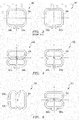
- FIGURE 1 shows an example of an existing inductor 100 commonly used in RF VCOs.
- the inductor 100 is a differential 1.25 nH inductor with an inductor coil 102 having two terminals 104.
- the positions of the terminals 104a and 104b have been optimized for connection to the rest of the VCO, including any varactors and MOS switches (not shown) that may be present, but little attention was paid to mutual EM coupling apart from keeping a certain minimum distance from other metal wires in the vicinity.
- FIGURE 2 shows an example of an inductor 200.
- the inductor 200 has an inductor coil 202 and terminals 204a and 204b, and has been designed so that it is substantially symmetrical about a horizontal axis X.
- the inductor coil 202 is in the form of a single-turn 8-shaped structure with an upper loop 206a and a lower loop 206b.
- current in the upper loop 206a travels in a direction (e.g., counterclockwise, see arrows) that is opposite to current in the lower loop 206b (e.g., clockwise).
- the EM field components emanating at a certain distance from the two substantially symmetrical loops 206a and 206b also have opposite directions and tend to counteract each other.
- the directions of the EM field components are indicated by conventional notation in the middle of each loop 206a and 206b. Consequently, the inductor 200 has been found to have a significantly reduced far field at a certain distance from the inductor coil 202.
- cancellation of a significant amount of far field on either side of the horizontal symmetry axis X may be achieved. It should be noted, however, that perfect symmetry between the two loops 206a and 206b may be difficult to achieve given the presence of the terminals 204a and 204b.
- the positioning of the terminals 204a and 204b may help minimize the far field. For example, positioning the two terminals 204a and 204b as close to each other as possible helps make the field contributions from the two parts of the inductor 200 identical. It is also desirable to minimize the additional loop external to the inductor 200 created by the connections to the varactors and switches. This extra loop may compromise the symmetry of the inductor itself to some extent and may reduce the canceling effect. In theory, it should be possible to modify the geometry of the inductor (e.g., make the upper loop slightly larger) to compensate for this effect. The symmetry of the inductor 200 with respect to a center vertical axis is also important for minimizing the generation of common-mode signal components.
- FIGURE 3 illustrates a prior art inductor arrangement of two O-shaped inductors 300 and 302.
- the two inductors 300 and 302 are placed side-by-side and have O-shaped inductor coils 304 and 306.
- the inductors coils 304 and 306 in this embodiment are substantially the same size as the 8-shaped inductor coil (e.g., 350 x 350 ⁇ m) of FIGURE 2 and are symmetrical relative to their vertical axes Y.
- the terminals for the two inductor coils 304 and 306 are labeled as 308a & 308b and 310a & 310b, respectively. Because each O-shaped inductor 300 and 302 provides little or no EM reduction individually, the arrangement as a whole provides little or no mutual EM coupling reduction.
- an inductor arrangement involving two 8-shaped inductors like the one in FIGURE 2 may provide further reduced mutual EM coupling.
- FIGURE 4 illustrates an inductor arrangement similar to the arrangement in FIGURE 3 is shown, except the two inductors 400 and 402 have 8-shaped inductor coils 404 and 406 instead of O-shaped inductor coils.
- the terminals for the inductor coils 404 and 406 are labeled as 408a & 408b and 410a & 410b, respectively.
- Each individual inductor 400 and 402 has a reduced far field by virtue of the 8-shaped inductor coil 404 and 406, as explained above with respect to FIGURE 2 .
- the two inductors 400 and 402 it is not necessary for the two inductors 400 and 402 to have the same size. All that is needed for mutual EM coupling reduction is for them to have similar EM reducing shapes. Further, a combination of an O-shaped inductor and an 8-shaped inductor may still result in mutual coupling reduction. However, since such an arrangement only uses the EM canceling effect of one inductor (the O-shaped inductor has little or no EM cancellation), the total isolation between the two inductors is less. In some embodiments, it has been found that even greater isolation may be achieved by rotating one of the inductor coils, as shown in FIGURE 5 .
- inductors 500 and 502 having nearly identical 8-shaped inductor coils 504 and 506 have again been placed side-by-side. Their terminals are again labeled as 508a & 508b and 510a & 510b, respectively. However, one of the inductor coils, say, the inductor coil 504 on the left, has been rotated by 90 degrees to further reduce mutual EM coupling.
- simulations were performed using the Momentum 2D EM SimulatorTM from Agilent Technologies, with some simulations also repeated in FastHenryTM from the Computational Prototyping Group to verify the results.
- the simulations used a simple semiconductor substrate model that described the metal and dielectric layers on top of a typical semiconductor substrate.
- the four terminals of the two mutually coupled inductors were defined as the ports of a linear 4-port network (see FIGURE 4 ).
- the interaction between the inductors in such a network may often be expressed using an s-parameter matrix.
- s-parameter theory is a general technique used to describe how signals are reflected and transmitted in a network.
- the upper left 2-by-2 sub-matrix contains the purely differential 2-port s-parameters, while the other sub-matrices contain the common-mode behavior.
- the differential voltage gain G vdd from the ports of the first inductor to the ports of the second inductor was calculated at 3.7 GHz.
- the corresponding coupling coefficient was then estimated based on s-parameter simulations on a test circuit with two coupled inductors. Table 1 shows a summary of the simulation results for the mutual coupling between different coil shapes and orientations for two inductors at a center distance of 1 mm.
- notation 8_shape_90 represents a figure-8 shaped inductor that has been rotated 90 degrees and the notation “8_shape_-90” represents a figure-8 shaped inductor that has been rotated by -90 degrees
- Q1 is the Q-factor for the Inductor 1
- Attt is the attenuation of the mutual EM coupling between the two inductors
- k is the estimated coupling coefficient.
- making one of the inductors 8-shaped was shown to reduce the mutual coupling by up to 20 dB.
- Making both of them 8-shaped was shown to improve the isolation by up to 30 dB.
- Making both connectors 8-shaped and rotating them by 90 degrees in opposite directions was shown to improve the isolation nearly 40 dB.
- Positioning of the inductors relative to each other may also affect the amount of mutual coupling.
- additional simulations were done where one of the inductor coils was offset from the ideal symmetry axis by a varying amount. This is illustrated in FIGURE 7 , where two inductors 700 and 702 having nearly identical 8-shaped inductor coils 704 and 706 are shown. As can be seen, however, the connector coil 704 on the left has been offset vertically from the ideal symmetry axis X by a certain distance Z to a new axis X'.
- Table 2 The details of the simulation are shown in Table 2 below, where Deg is the degradation in dB.
- FIGURE 8 To verify the results of the coupling coefficient estimation, an alternative tool FastHenryTM was used to calculate k.
- the simulated results are plotted in FIGURE 8 .
- the horizontal axis again represents the distance between the centers of the inductors in mm, but the vertical axis now represents the coupling coefficient k
- the bottom plot 800 represents the FastHenryTM results
- the top plot 802 represents the Momentum 2D EM SimulatorTM results.
- the agreement between the two sets of results appears quite good for distances up to 1.5 mm, but some discrepancy may be noted at 2 mm. The most likely explanation for the discrepancy is that the Momentum 2D EM SimulatorTM results are more reliable.
- the layout of the rest of the VCO should be designed to minimize any additional inductor loops that may be created when the inductor is connected to the VCO components (e.g., varicaps and capacitive switches), since the magnetic field from this additional loop will affect the balance between the up field components of opposite signs and reduce any canceling effect.
- FIGURE 9 shows an exemplary layout for a typical 4 GHz VCO 900 with an 8-shaped inductor 902 that may be used to minimize any additional inductor loops.
- the layout for the resonator e.g., switches, varactor
- the supply voltage e.g., bias and decoupling
- all capacitive resonator components are fully differential and have a symmetrical layout.
- FIGURE 10 illustrates an example of a four-leaf clover-shaped inductor 1000.
- the four loops 1002, 1004, 1006, and 1008 of the inductor 1000 are connected in such a way that the magnetic field emanating from any two adjacent loops have opposite directions and tend to cancel one another.
- the cancellation of the different magnetic field components is less dependent, for example, on the direction of the second inductor coil where two four-leaf clover-shaped inductors are present on the same chip.
- FIGURE 12 a configuration where one of the inductors (e.g., inductor 1100) is rotated 45 degrees relative to the other inductor (e.g., inductor 1102) has been observed to have even lower EM coupling between the two inductors 1100 and 1102.
- the differential transfer gain G vdd is plotted in FIGURE 12 for two four-leaf clover shaped inductor arrangement (plot 1200) as a function of center distance together with the performance of two 8-shaped inductors (plot 1202) and two O-shaped inductors (plot 1204).
- One of the four-leaf clover shaped inductors has been rotated by about 45 degrees (indicated by the "r") and likewise one of the 8-shaped inductors has been rotated by about 90 degrees (again indicated by the "r").
- the vertical axis of the chart represents the differential transfer gain G vdd and the horizontal axis represents the center distance.
- the isolation for the two four-leaf clover shaped inductor arrangement is nearly 10 dB better than the 8-shaped inductor arrangement for distances below 1 mm and show no resonant behavior at larger distances.
- FIGURE 13 An example of a two-turn 8-shaped inductor 1300 is shown in FIGURE 13 .
- the two-turn 8-shaped inductor 1300 is essentially similar to the 8-shaped inductor 200 of FIGURE 2 , except that the two outer loops 1302 and 1304 of the inductor 1300 each turn into an inner loop 1306 and 1308, respectively.
- the terminals 1310a and 1310b of the inductor 1300 are then connected to the lower inner loop 1308.
- Such a two-turn inductor 1300 may provide a higher inductance value without taking up too much chip area, while also reducing the Q-factor.
- the Q-factor may be reduced from approximately 15 to 12.5 at 4 GHz.
Landscapes
- Engineering & Computer Science (AREA)
- Power Engineering (AREA)
- Microelectronics & Electronic Packaging (AREA)
- Coils Or Transformers For Communication (AREA)
- Semiconductor Integrated Circuits (AREA)
Description
- The present invention relates to voltage-controlled oscillators (VCO) of the type used in radio frequency (RF) transceivers and, in particular, to an improved inductor design in a VCO.
- Recent advances in wireless communication technology have allowed an entire RF transceiver to be implemented on a single semiconductor die or chip. However, integrating a complete RF transceiver on a single chip presents a number of challenges. For example, in wideband code division multiple access (WCDMA) transceivers, a single-chip solution requires two RF VCOs to be running on the chip at the same time. Such an arrangement may produce undesired interaction between the two VCOs due to various types of mutual coupling mechanisms, which may result in spurious receiver responses and unwanted frequencies in the transmit spectrum. The primary mutual coupling mechanism is usually the fundamental electromagnetic (EM) coupling between the resonators, i.e., the large inductor structures in the VCOs.
- A number of techniques exist for reducing the mutual EM coupling between the VCOs due to the inductors. One technique involves reduction of EM coupling by careful design of the inductors to provide maximum isolation of the inductors. Another technique calls for frequency separation by operating the two VCOs at different even harmonics of the desired frequency. Still another technique involves frequency separation by using a regenerative VCO concept. The frequency separation methods exploit the filtering properties of the resonator to reduce interference. However, these solutions require additional circuitry (dividers, mixers, etc.) that may increase current consumption, making them less attractive than other mutual EM coupling reduction alternatives.
-
WO 2004/012213 A1 discloses a planar inductance with planar spiral windings, wherein each winding is in the form of an "eight" with three cross-conductors carrying current in the same direction and running between two loops. - An inductor design for reducing mutual EM coupling between VCO resonators and a method of implementing the same on a single semiconductor chip. A method and system involve using inductors that are substantially symmetrical about their horizontal and/or their vertical axes and providing current to the inductors in a way so that the resulting magnetic field components tend to cancel each other by virtue of the symmetry. In addition, two such inductors may be placed near each other and oriented in a way so that the induced current in the second inductor due to the magnetic field originating from first inductor is significantly reduced. The inductors may be 8-shaped, four-leaf clover-shaped, single-turn, multi-turn, rotated relative to one another, and/or vertically offset relative to one another.
- In general, in one aspect, an inductor having a reduced far field comprises a first loop having a shape that is substantially symmetrical about a first predefined axis, and a second loop having a size and shape substantially identical to a size and shape of the first loop. The second loop is arranged such that a magnetic field emanating therefrom tends to cancel a magnetic field emanating from the first loop.
- In general, in another aspect, a method of reducing mutual electromagnetic coupling between two inductors on a semiconductor die comprises the step of forming a first inductor on the semiconductor die having a shape that is substantially symmetrical about a first predefined axis, the shape causing the first inductor to have a reduced far field, at least in some directions. The method further comprises the step of forming a second inductor on the semiconductor die at a predetermined distance from the first inductor, wherein a mutual electromagnetic coupling between the first inductor and the second inductor is reduced as a result of the first inductor having a reduced far field.
- In general, in another aspect, an inductor layout having reduced mutual electromagnetic coupling comprises a first inductor having a shape that is substantially symmetrical about a first predefined axis, the shape causing the first inductor to have a reduced electromagnetic field at a certain distance from the first inductor, at least in some directions. The inductor layout further comprises a second inductor positioned at a predetermined distance from the first inductor, wherein a mutual electromagnetic coupling between the first inductor and the second inductor is reduced as a result of the first inductor having a reduced electromagnetic field.
- It should be emphasized that the term comprises/comprising, when used in this specification, is taken to specify the presence of stated features, integers, steps, or components, but does not preclude the presence or addition of one or more other features, integers, steps, components, or groups thereof.
- The foregoing and other advantages of the invention will become apparent from the following detailed description and upon reference to the drawings, wherein:
-
FIGURE 1 illustrates a prior art O-shaped inductor; -
FIGURE 2 illustrates an 8-shaped inductor; -
FIGURE 3 illustrates a prior art O-shaped inductor arrangement; -
FIGURE 4 illustrates an 8-shaped inductor arrangement; -
FIGURE 5 illustrates an 8-shaped inductor arrangement wherein one inductor is rotated; -
FIGURE 6 illustrates the impact of distance on EM coupling using the 8-shaped inductor arrangement; -
FIGURE 7 illustrates an 8-shaped inductor arrangement wherein one inductor is offset from the other inductor; -
FIGURE 8 illustrates the impact of distance on decoupling coefficient using the inductor arrangements; -
FIGURE 9 illustrates a VCO layout wherein symmetry is retained; -
FIGURE 10 illustrates a four-leaf clover shaped inductor; -
FIGURE 11 illustrates a four-leaf clover shaped inductor arrangement; -
FIGURE 12 illustrates the impact of distance on EM coupling using the four-leaf clover shaped inductor arrangement; and -
FIGURE 13 illustrates a two-turn 8-shaped inductor. - As mentioned above, various embodiments of the invention provide an inductor design and method of implementing the same where mutual EM coupling is reduced. The inductor design and method serve to reduce the EM field at a certain distance from the inductor (i.e., the far field), at least in some directions, by using inductor shapes that are substantially symmetrical. As used herein, the term "symmetrical" refers to symmetry relative to at least one axis. This reduced far field may then be used to reduce the mutual coupling between two inductors. The inductor design and method may also be used to reduce the coupling between an inductor and another on-chip or external structure (e.g., an external power amplifier). This helps reduces the sensitivity of the VCO to interfering signals from other than a second on-chip VCO.
- Choosing a substantially symmetrical shape (e.g., a figure-8 or a four-leaf clover shape) for the first inductor helps reduce the EM field at far distances. This will, in turn, reduce mutual EM coupling to the second inductor, regardless of its shape. If the second inductor also has a similar or substantially identical shape, the tendency of the second inductor to pick up the EM field from the first inductor is also reduced via the same mechanisms. Thus, the overall isolation between the two inductors is further improved. Note, however, that the two inductors need not have the same size or the same shape as long as they have a substantially symmetrical shape. To the extent identical inductor layouts are shown in the figures, it is for illustrative purposes only.
- Further, although various embodiments of the invention are described herein mainly with respect to VCO-related isolation issues, RF amplifiers and mixers with tuned LC loads or inductive degeneration may also couple to each other or to a VCO and create interference problems. Thus, a person having ordinary skill in the art will appreciate that the inductor design and method may be used to reduce coupling between two functional blocks of any type so long as each contains one or more inductors.
- In order to reduce EM coupling between two inductors, it is typically necessary to reduce the far field generated by the inductor coils. Unfortunately, this is not a simple task because there are many topological constraints on a planar integrated inductor. For example, a typical inductor design uses two or more stacked metal layers. Normally the top layer is much thicker (i.e., has lower resistance) than the other layers. It is therefore desirable to mainly use this layer in order to achieve a maximum Q-factor. Where the wires are crossing, thinner metal layers are usually used and careful design of the crossings is needed to combine high Q-factor with minimum coupling. Further, negative electromagnetic coupling between parallel wire segments close to each other should be avoided so that the inductance per wire length unit is maximized. However, by exploiting the symmetry of the inductor in one or more dimensions together with controlling the EM field components emanating from different parts of the inductor coil, the far field may be reduced in some directions due to canceling effects.
- Existing VCO inductor designs are optimized for maximum Q-factor given the constraints regarding silicon area, wire width, and the like.
FIGURE 1 shows an example of an existinginductor 100 commonly used in RF VCOs. Theinductor 100 is a differential 1.25 nH inductor with aninductor coil 102 having two terminals 104. As can be seen, the positions of theterminals 104a and 104b have been optimized for connection to the rest of the VCO, including any varactors and MOS switches (not shown) that may be present, but little attention was paid to mutual EM coupling apart from keeping a certain minimum distance from other metal wires in the vicinity. -
FIGURE 2 shows an example of aninductor 200. Theinductor 200 has aninductor coil 202 andterminals inductor coil 202 is in the form of a single-turn 8-shaped structure with anupper loop 206a and alower loop 206b. By virtue of the figure-8 shape, current in theupper loop 206a travels in a direction (e.g., counterclockwise, see arrows) that is opposite to current in thelower loop 206b (e.g., clockwise). As a result, the EM field components emanating at a certain distance from the two substantiallysymmetrical loops loop inductor 200 has been found to have a significantly reduced far field at a certain distance from theinductor coil 202. Thus, by making the twoloops loops terminals - In addition, the positioning of the
terminals terminals inductor 200 identical. It is also desirable to minimize the additional loop external to theinductor 200 created by the connections to the varactors and switches. This extra loop may compromise the symmetry of the inductor itself to some extent and may reduce the canceling effect. In theory, it should be possible to modify the geometry of the inductor (e.g., make the upper loop slightly larger) to compensate for this effect. The symmetry of theinductor 200 with respect to a center vertical axis is also important for minimizing the generation of common-mode signal components. - Other considerations may include basic layout parameters, such as the width and height of the
inductor coil 202 together with the width and spacing of the surrounding metal wires. These parameters, however, are mainly determined by requirements on inductance, Q-factor, chip area, and process layout rules and have only minor influence on mutual coupling characteristics as long as symmetry of the inductor coil is maintained. -
FIGURE 3 illustrates a prior art inductor arrangement of two O-shapedinductors inductors FIGURE 2 and are symmetrical relative to their vertical axes Y. The terminals for the twoinductor coils inductor - On the other hand, an inductor arrangement involving two 8-shaped inductors like the one in
FIGURE 2 may provide further reduced mutual EM coupling. This is illustrated inFIGURE 4 , where an inductor arrangement similar to the arrangement inFIGURE 3 is shown, except the twoinductors individual inductor inductor coil FIGURE 2 . In addition, there is also a reduction in the mutual coupling between the twoinductors - Note that it is not necessary for the two
inductors FIGURE 5 . Here, twoinductors inductor coil 504 on the left, has been rotated by 90 degrees to further reduce mutual EM coupling. - In addition to the above designs, other more complex inductor designs that are symmetrical in more than one dimension, for example, a four-leaf clover shape, may also be used. These complex inductor designs are useful because higher inductance values typically need to have more than one turn in order not to consume too much chip area. In addition, such complex inductor designs are often less sensitive to sub-optimal placement and orientation.
- To determine the effectiveness of the above inductor designs in reducing mutual EM coupling, simulations were performed using the Momentum 2D EM Simulator™ from Agilent Technologies, with some simulations also repeated in FastHenry™ from the Computational Prototyping Group to verify the results. The simulations used a simple semiconductor substrate model that described the metal and dielectric layers on top of a typical semiconductor substrate. The four terminals of the two mutually coupled inductors were defined as the ports of a linear 4-port network (see
FIGURE 4 ). The interaction between the inductors in such a network may often be expressed using an s-parameter matrix. Those having ordinary skill in the art understand that s-parameter theory is a general technique used to describe how signals are reflected and transmitted in a network. The below s-parameter matrix S gives a substantially complete description of the network's behavior when it is connected to the surrounding components.
- However, the mutual coupling between the two inductors is often difficult to extract directly from the s-parameters where, as here, the network has four single-ended ports. For this type of analysis, it is sometimes more convenient to treat the two inductors as a differential 2-port network by transforming the single-ended s-parameter matrix into a mixed-mode s-parameter matrix Smm:


- As can be seen, the upper left 2-by-2 sub-matrix contains the purely differential 2-port s-parameters, while the other sub-matrices contain the common-mode behavior. The voltage transfer gain Gvdd was then calculated using standard 2-port s-parameter formulas, for example:

- This theoretical gain parameter Gvdd extracted from the 4-port s-parameter simulation results was then used to compare the mutual coupling between different combinations of inductor layouts.
- Using the above mixed-mode s-parameters, the differential voltage gain Gvdd from the ports of the first inductor to the ports of the second inductor was calculated at 3.7 GHz. The corresponding coupling coefficient was then estimated based on s-parameter simulations on a test circuit with two coupled inductors. Table 1 shows a summary of the simulation results for the mutual coupling between different coil shapes and orientations for two inductors at a center distance of 1 mm. In Table 1, the "notation 8_shape_90" represents a figure-8 shaped inductor that has been rotated 90 degrees and the notation "8_shape_-90" represents a figure-8 shaped inductor that has been rotated by -90 degrees, "Q1" is the Q-factor for the Inductor 1, "Att" is the attenuation of the mutual EM coupling between the two inductors, and k is the estimated coupling coefficient.
Table 1 Inductor 1 Inductor 2 L1 [nH] Q1 Gvdd [dB] Att [dB] K O-shape O-shape 0.841 16.93 -54.0 reference 0.002077 8-shape O-shape 1.216 15.20 -75.6 21.6 0.000173 8-shape_90 O-shape 1.218 15.63 -74.9 20.9 0.000187 8-shape 8-shape 1.216 15.84 -86.5 32.5 0.000049 8-shape_90 8-shape 1.216 15.19 -89.7 35.7 0.000034 8-shape_90 8-shape_-90 1.216 15.69 -92.8 38.8 0.000024 - As can be seen, making one of the inductors 8-shaped was shown to reduce the mutual coupling by up to 20 dB. Making both of them 8-shaped was shown to improve the isolation by up to 30 dB. Making both connectors 8-shaped and rotating them by 90 degrees in opposite directions was shown to improve the isolation nearly 40 dB.
- A second series of simulations was performed where the center distance between the coils was varied from 0.5 mm up to 2.0 mm for two 8-shaped inductors compared to two O-shaped inductors. The results are plotted in
FIGURE 6 , where the vertical axis represents the differential transfer gain Gvdd and the horizontal axis represents the distance between the centers of the two inductors in millimeters (mm). As can be seen, the 8-shaped inductors (plot 600) resulted in much lower mutual coupling relative to the O-shaped inductors (plot 602). In addition, the 8-shaped inductors show a degree of resonant behavior where the mutual coupling is very low at a certain distance (depending on the frequency). The "average" isolation improvement for the second series (ignoring the sharp minima near 2.0 mm) is between 30 and 40 dB. - Positioning of the inductors relative to each other may also affect the amount of mutual coupling. In order to get an understanding of how much the positioning of the inductors affects mutual coupling, additional simulations were done where one of the inductor coils was offset from the ideal symmetry axis by a varying amount. This is illustrated in
FIGURE 7 , where twoinductors connector coil 704 on the left has been offset vertically from the ideal symmetry axis X by a certain distance Z to a new axis X'. The details of the simulation are shown in Table 2 below, where Deg is the degradation in dB. With this arrangement, some degradation of the inductor isolation was observed, but even at a 1 mm offset, which corresponds to an orientation of 45 degrees, an improvement of about 30 dB in mutual coupling reduction is achieved for the 8-shaped inductor.Table 2 Offset [mm] L1 [nH] Q1 Gvdd [dB] Att [dB] Deg [dB] k estim 0.0 1.216 15.19 -89.7 35.7 reference 0.000034 0.1 1.216 15.19 -85.3 31.3 4.4 0.000057 0.2 1.216 15.19 -82.5 28.5 7.2 0.000078 0.3 1.216 15.19 -81.0 27.0 8.7 0.000093 0.5 1.216 15.19 -81.8 27.8 7.9 0.000085 0.7 1.216 15.19 -85.8 31.8 3.9 0.000053 1.0 1.216 15.19 -103.4 49.4 -13.7 0.000007 - To investigate the relationship between differential voltage gain Gvdd and coupling coefficient k, s-parameter simulations of the two inductors were performed in Spectre™. Thereafter, an estimated coupling coefficient k was able to be calculated from Momentum 2D EM Simulator™ results and included in Table 1 and Table 2.
- To verify the results of the coupling coefficient estimation, an alternative tool FastHenry™ was used to calculate k. The simulated results are plotted in
FIGURE 8 . InFIGURE 8 the horizontal axis again represents the distance between the centers of the inductors in mm, but the vertical axis now represents the coupling coefficient k, thebottom plot 800 represents the FastHenry™ results, and thetop plot 802 represents the Momentum 2D EM Simulator™ results. The agreement between the two sets of results appears quite good for distances up to 1.5 mm, but some discrepancy may be noted at 2 mm. The most likely explanation for the discrepancy is that the Momentum 2D EM Simulator™ results are more reliable. - From the foregoing, it can be clearly seen that mutual coupling reduction is closely related to the symmetry of the inductor. Therefore, the layout of the rest of the VCO should be designed to minimize any additional inductor loops that may be created when the inductor is connected to the VCO components (e.g., varicaps and capacitive switches), since the magnetic field from this additional loop will affect the balance between the up field components of opposite signs and reduce any canceling effect.
-
FIGURE 9 shows an exemplary layout for a typical 4GHz VCO 900 with an 8-shapedinductor 902 that may be used to minimize any additional inductor loops. As can be seen, the layout for the resonator (e.g., switches, varactor) and active parts is substantially symmetrical around the vertical axis Y. The supply voltage (e.g., bias and decoupling) is also applied symmetrically, with the wires routed on top of each other so that they will not create an additional loop. Preferably, all capacitive resonator components are fully differential and have a symmetrical layout. - As alluded to above, more complex inductor designs that are symmetrical in more than one dimension, for example, a four-leaf clover shape design, may also be used. In general, by increasing the number of loops from two to four, the canceling effect may be improved further in some directions and for some distances. This is because, in general (and at least for the 8-shaped inductors), the isolation between inductors is dependent on the relative placement of the coils.
FIGURE 10 illustrates an example of a four-leaf clover-shapedinductor 1000. The fourloops inductor 1000 are connected in such a way that the magnetic field emanating from any two adjacent loops have opposite directions and tend to cancel one another. Thus, the cancellation of the different magnetic field components is less dependent, for example, on the direction of the second inductor coil where two four-leaf clover-shaped inductors are present on the same chip. - Furthermore, as shown in
FIGURE 12 , a configuration where one of the inductors (e.g., inductor 1100) is rotated 45 degrees relative to the other inductor (e.g., inductor 1102) has been observed to have even lower EM coupling between the twoinductors - The differential transfer gain Gvdd is plotted in
FIGURE 12 for two four-leaf clover shaped inductor arrangement (plot 1200) as a function of center distance together with the performance of two 8-shaped inductors (plot 1202) and two O-shaped inductors (plot 1204). One of the four-leaf clover shaped inductors has been rotated by about 45 degrees (indicated by the "r") and likewise one of the 8-shaped inductors has been rotated by about 90 degrees (again indicated by the "r"). The vertical axis of the chart represents the differential transfer gain Gvdd and the horizontal axis represents the center distance. As can be seen, the isolation for the two four-leaf clover shaped inductor arrangement is nearly 10 dB better than the 8-shaped inductor arrangement for distances below 1 mm and show no resonant behavior at larger distances. - The improvement in the directional behavior of the four-leaf clover shaped inductor arrangement is shown in Table 3. As can be seen, there is no degradation in isolation when moving away from the symmetry axis, only a smaller improvement due to the increasing distance. However, due to the more complex wire layout, resulting in less inductance per length of wire, the Q-factor is slightly lower compared to the 8-shaped inductor arrangement.
Table 3 Offset [mm] L1 [nH] Q1 Gvdd [dB] Att [dB] Deg [dB] k estim 0.0 1.300 13.09 -92.5 38.5 reference 0.000025 0.1 1.300 13.09 -92.9 38.9 -0.4 0.000024 0.2 1.300 13.09 -92.9 38.9 -0.4 0.000024 0.3 1.300 13.09 -93.4 39.4 -0.9 0.000022 0.5 1.300 13.09 -94.1 40.1 -1.6 0.000021 0.7 1.300 13.09 -94.9 40.9 -2.4 0.000019 1.0 1.300 13.09 -97.1 43.1 -4.6 0.000015 - In applications where higher inductance values are needed, it is possible to use inductor coils with more than one turn, since single turn designs tend to take up too much chip area. An example of a two-turn 8-shaped
inductor 1300 is shown inFIGURE 13 . As can be seen, the two-turn 8-shapedinductor 1300 is essentially similar to the 8-shapedinductor 200 ofFIGURE 2 , except that the twoouter loops inductor 1300 each turn into aninner loop terminals inductor 1300 are then connected to the lowerinner loop 1308. Such a two-turn inductor 1300 may provide a higher inductance value without taking up too much chip area, while also reducing the Q-factor. In the embodiment shown here, the Q-factor may be reduced from approximately 15 to 12.5 at 4 GHz. - Although a two-turn 8-shaped inductor has been shown, other configurations may also be used, such as a two-turn four-leaf clover shaped inductor, provided that near symmetry can be maintained given the crossing of the inner and outer loops and positioning requirements of the terminals. Other symmetrical shapes besides those described thus far may also show the same or even better coupling reduction if a satisfactory balance between parameters such as Q-factor, coil size, and coupling coefficient can be reached.
Claims (13)
- A semiconductor die having formed thereon:a first inductor (200, 1000, 1300) comprising an inductor coil (202) and terminals (204a, 204b; 1310a, 1310b), wherein the first inductor (200, 1000, 1300) is substantially symmetric about a symmetry axis, wherein the inductor coil (202) has a first loop (206a; 1004) and a second loop (206b; 1008) arranged such that current in the first loop (206a; 1004; 1002) travels in a direction that is opposite to current in the second loop (206b; 1008) such that electromagnetic field components emanating at a certain distance from the first loop (206a; 1004) and the second loop (206b; 1008) also have opposite directions and tend to counteract each other;characterized in thatthe terminals (204a, 204b; 1310a, 1310b) are connected to the second loop (206b, 1008).
- The semiconductor die according to claim 1, wherein the terminals (204a, 204b; 1310a, 1310b) are positioned at a side of the second loop (206b, 1008) that is opposite to the first loop (2006a, 1004).
- The semiconductor die according to claim 1 or 2, wherein the terminals (204a, 204b; 1310a, 1310b) are positioned such as to minimize the far field emanating from the inductor.
- The semiconductor die according to claim 1, 2, or 3, wherein the terminals (204a, 204b) are positioned closely.
- The semiconductor die according to any preceding claim, wherein the inductor coil (202) has more than one turn.
- The semiconductor die according to any preceding claim, wherein the inductor coil (202) is in the form of an eight-shaped structure.
- The semiconductor die according to any of the claims 1-5, wherein the inductor (1000) is four-leaf clover shaped.
- The semiconductor die according to any of the claims 1-5, wherein the inductor coil has four loops.
- The semiconductor die according to any of the claims 1-8, comprising an inductor arrangement, the inductor arrangement comprising the first inductor and a second inductor.
- The semiconductor die according to claim 9, wherein the second inductor has the same shape as the first inductor.
- The semiconductor die according to any of the claims 1-10, comprising a first voltage-controlled oscillator comprising the first inductor.
- The semiconductor die according to claim 9 or 10, comprising a first voltage-controlled oscillator comprising the first inductor and a second voltage-controlled oscillator comprising the second inductor.
- The semiconductor die according to claim 11 or 12, comprising a radio frequency transceiver comprising the first voltage-controlled oscillator.
Priority Applications (2)
| Application Number | Priority Date | Filing Date | Title |
|---|---|---|---|
| EP19183992.7A EP3567614A1 (en) | 2004-03-03 | 2005-02-15 | Method of and inductor layout for reduced vco coupling |
| PL14172888T PL2819131T3 (en) | 2004-03-03 | 2005-02-15 | Inductor layout for reduced VCO coupling |
Applications Claiming Priority (5)
| Application Number | Priority Date | Filing Date | Title |
|---|---|---|---|
| US54961104P | 2004-03-03 | 2004-03-03 | |
| US56532804P | 2004-04-26 | 2004-04-26 | |
| US10/919,130 US7151430B2 (en) | 2004-03-03 | 2004-08-16 | Method of and inductor layout for reduced VCO coupling |
| PCT/EP2005/001515 WO2005096328A1 (en) | 2004-03-03 | 2005-02-15 | Method and inductor layout for reduced vco coupling |
| EP05715341.3A EP1721324B3 (en) | 2004-03-03 | 2005-02-15 | Method and inductor layout for reduced vco coupling |
Related Parent Applications (2)
| Application Number | Title | Priority Date | Filing Date |
|---|---|---|---|
| EP05715341.3A Division EP1721324B3 (en) | 2004-03-03 | 2005-02-15 | Method and inductor layout for reduced vco coupling |
| EP05715341.3A Division-Into EP1721324B3 (en) | 2004-03-03 | 2005-02-15 | Method and inductor layout for reduced vco coupling |
Related Child Applications (2)
| Application Number | Title | Priority Date | Filing Date |
|---|---|---|---|
| EP19183992.7A Division-Into EP3567614A1 (en) | 2004-03-03 | 2005-02-15 | Method of and inductor layout for reduced vco coupling |
| EP19183992.7A Division EP3567614A1 (en) | 2004-03-03 | 2005-02-15 | Method of and inductor layout for reduced vco coupling |
Publications (2)
| Publication Number | Publication Date |
|---|---|
| EP2819131A1 EP2819131A1 (en) | 2014-12-31 |
| EP2819131B1 true EP2819131B1 (en) | 2019-08-14 |
Family
ID=34916337
Family Applications (3)
| Application Number | Title | Priority Date | Filing Date |
|---|---|---|---|
| EP19183992.7A Pending EP3567614A1 (en) | 2004-03-03 | 2005-02-15 | Method of and inductor layout for reduced vco coupling |
| EP05715341.3A Expired - Lifetime EP1721324B3 (en) | 2004-03-03 | 2005-02-15 | Method and inductor layout for reduced vco coupling |
| EP14172888.1A Expired - Lifetime EP2819131B1 (en) | 2004-03-03 | 2005-02-15 | Inductor layout for reduced VCO coupling |
Family Applications Before (2)
| Application Number | Title | Priority Date | Filing Date |
|---|---|---|---|
| EP19183992.7A Pending EP3567614A1 (en) | 2004-03-03 | 2005-02-15 | Method of and inductor layout for reduced vco coupling |
| EP05715341.3A Expired - Lifetime EP1721324B3 (en) | 2004-03-03 | 2005-02-15 | Method and inductor layout for reduced vco coupling |
Country Status (11)
| Country | Link |
|---|---|
| US (1) | US7151430B2 (en) |
| EP (3) | EP3567614A1 (en) |
| JP (1) | JP2007526642A (en) |
| KR (3) | KR101298288B1 (en) |
| CN (1) | CN1950913B (en) |
| DK (1) | DK2819131T3 (en) |
| ES (2) | ES2510468T7 (en) |
| HU (1) | HUE045971T2 (en) |
| PL (2) | PL2819131T3 (en) |
| PT (1) | PT2819131T (en) |
| WO (1) | WO2005096328A1 (en) |
Cited By (1)
| Publication number | Priority date | Publication date | Assignee | Title |
|---|---|---|---|---|
| US12438548B2 (en) | 2021-03-26 | 2025-10-07 | Telefonaktiebolaget Lm Ericsson (Publ) | Multiple PLL system with phase locking and phase noise cancellation |
Families Citing this family (115)
| Publication number | Priority date | Publication date | Assignee | Title |
|---|---|---|---|---|
| DE10233980A1 (en) * | 2002-07-25 | 2004-02-12 | Philips Intellectual Property & Standards Gmbh | planar inductor |
| KR100579136B1 (en) * | 2004-12-16 | 2006-05-12 | 한국전자통신연구원 | Transformer with Variable Inductance |
| GB0523969D0 (en) * | 2005-11-25 | 2006-01-04 | Zarlink Semiconductor Ltd | Inductivwe component |
| JP2007288741A (en) * | 2006-04-20 | 2007-11-01 | Alps Electric Co Ltd | Loose coupling coil |
| EP2038902B1 (en) * | 2006-07-07 | 2017-10-04 | Nxp B.V. | Programmable inductor |
| US7535330B2 (en) * | 2006-09-22 | 2009-05-19 | Lsi Logic Corporation | Low mutual inductance matched inductors |
| DE102007051307B4 (en) * | 2007-10-26 | 2011-02-17 | Siemens Medical Instruments Pte. Ltd. | Hearing device with use of an inductive switching regulator as a radio transmitter |
| WO2009101565A1 (en) * | 2008-02-14 | 2009-08-20 | Nxp B.V. | Optimized layout for low magnetic stray-field inductor |
| EP2253088A1 (en) | 2008-02-14 | 2010-11-24 | Nxp B.V. | Method of correction of network synchronisation |
| CN101990690B (en) * | 2008-04-10 | 2013-10-09 | Nxp股份有限公司 | 8-shaped inductor |
| WO2009128047A1 (en) * | 2008-04-18 | 2009-10-22 | Nxp B.V. | High density inductor, having a high quality factor |
| US8421577B2 (en) * | 2008-04-21 | 2013-04-16 | Nxp B.V. | Planar inductive unit and an electronic device comprising a planar inductive unit |
| JP2010056856A (en) * | 2008-08-28 | 2010-03-11 | Renesas Technology Corp | Semiconductor integrated circuit |
| GB2462885B (en) | 2008-08-29 | 2013-03-27 | Cambridge Silicon Radio Ltd | Inductor structure |
| GR1006723B (en) | 2009-01-16 | 2010-03-09 | ������������ ������������-������� ����������� ����������� ��������� ������� (���� ������� 5%) | Integral or printed daisy-like coil |
| EP2273613A1 (en) | 2009-07-07 | 2011-01-12 | Nxp B.V. | Magnetic shield layout, semiconductor device and application |
| EP2293309A1 (en) | 2009-09-08 | 2011-03-09 | STmicroelectronics SA | Integrated inductive device |
| GB0918221D0 (en) * | 2009-10-16 | 2009-12-02 | Cambridge Silicon Radio Ltd | Inductor structure |
| JP2011159953A (en) * | 2010-01-05 | 2011-08-18 | Fujitsu Ltd | Electronic circuit and electronic device |
| EP2421011A1 (en) * | 2010-08-19 | 2012-02-22 | Nxp B.V. | Symmetrical inductor |
| US9196409B2 (en) * | 2010-12-06 | 2015-11-24 | Nxp, B. V. | Integrated circuit inductors |
| US20120244802A1 (en) * | 2011-03-24 | 2012-09-27 | Lei Feng | On chip inductor |
| KR20130023622A (en) * | 2011-08-29 | 2013-03-08 | 삼성전기주식회사 | Conductor pattern and electronic component having the same |
| US8576039B2 (en) * | 2011-12-06 | 2013-11-05 | Cambridge Silicon Radio Limited | Inductor structure |
| HUE025783T2 (en) * | 2012-04-03 | 2016-05-30 | ERICSSON TELEFON AB L M (publ) | Coil arrangement and voltage controlled oscillator (VCO) system |
| CN102738125B (en) * | 2012-06-29 | 2015-01-28 | 杭州电子科技大学 | New fractal PFS structure |
| DE102012112571B3 (en) | 2012-12-18 | 2014-06-05 | Epcos Ag | circuitry |
| US8860521B2 (en) * | 2012-12-19 | 2014-10-14 | Intel IP Corporation | Variable inductor for LC oscillator |
| US12224096B2 (en) | 2013-03-15 | 2025-02-11 | Qorvo Us, Inc. | Advanced 3D inductor structures with confined magnetic field |
| US9871499B2 (en) | 2013-03-15 | 2018-01-16 | Qorvo Us, Inc. | Multi-band impedance tuners using weakly-coupled LC resonators |
| US9048836B2 (en) | 2013-08-01 | 2015-06-02 | RF Mirco Devices, Inc. | Body bias switching for an RF switch |
| US9742359B2 (en) | 2013-03-15 | 2017-08-22 | Qorvo International Pte. Ltd. | Power amplifier with wide dynamic range am feedback linearization scheme |
| US9774311B2 (en) | 2013-03-15 | 2017-09-26 | Qorvo Us, Inc. | Filtering characteristic adjustments of weakly coupled tunable RF filters |
| US9755671B2 (en) | 2013-08-01 | 2017-09-05 | Qorvo Us, Inc. | VSWR detector for a tunable filter structure |
| US9780756B2 (en) | 2013-08-01 | 2017-10-03 | Qorvo Us, Inc. | Calibration for a tunable RF filter structure |
| US9825656B2 (en) | 2013-08-01 | 2017-11-21 | Qorvo Us, Inc. | Weakly coupled tunable RF transmitter architecture |
| US9705478B2 (en) | 2013-08-01 | 2017-07-11 | Qorvo Us, Inc. | Weakly coupled tunable RF receiver architecture |
| US9628045B2 (en) | 2013-08-01 | 2017-04-18 | Qorvo Us, Inc. | Cooperative tunable RF filters |
| US9899133B2 (en) | 2013-08-01 | 2018-02-20 | Qorvo Us, Inc. | Advanced 3D inductor structures with confined magnetic field |
| US9484879B2 (en) | 2013-06-06 | 2016-11-01 | Qorvo Us, Inc. | Nonlinear capacitance linearization |
| US9685928B2 (en) | 2013-08-01 | 2017-06-20 | Qorvo Us, Inc. | Interference rejection RF filters |
| US9859863B2 (en) | 2013-03-15 | 2018-01-02 | Qorvo Us, Inc. | RF filter structure for antenna diversity and beam forming |
| US9444417B2 (en) | 2013-03-15 | 2016-09-13 | Qorvo Us, Inc. | Weakly coupled RF network based power amplifier architecture |
| DE102013104842B4 (en) | 2013-05-10 | 2015-11-12 | Epcos Ag | Miniaturized RF component with reduced coupling |
| US9800282B2 (en) | 2013-06-06 | 2017-10-24 | Qorvo Us, Inc. | Passive voltage-gain network |
| US9705542B2 (en) | 2013-06-06 | 2017-07-11 | Qorvo Us, Inc. | Reconfigurable RF filter |
| US9966981B2 (en) | 2013-06-06 | 2018-05-08 | Qorvo Us, Inc. | Passive acoustic resonator based RF receiver |
| US9780817B2 (en) | 2013-06-06 | 2017-10-03 | Qorvo Us, Inc. | RX shunt switching element-based RF front-end circuit |
| RU2552514C2 (en) * | 2013-07-08 | 2015-06-10 | Корпорация "САМСУНГ ЭЛЕКТРОНИКС Ко., Лтд." | Planar device for generating magnetic field with arbitrary direction |
| US10186371B2 (en) * | 2013-07-08 | 2019-01-22 | Samsung Electronics Co., Ltd. | Magnetic field generation apparatus having planar structure |
| EP3220419B1 (en) | 2013-10-16 | 2020-07-08 | Telefonaktiebolaget LM Ericsson (publ) | Transceiver, receiver and communication device with switch arrangement |
| EP3223309B1 (en) | 2013-10-16 | 2020-07-08 | Telefonaktiebolaget LM Ericsson (publ) | Transceiver, receiver and communication device with tunable inductor arrangement |
| US9473152B2 (en) | 2013-11-08 | 2016-10-18 | Taiwan Semiconductor Manufacturing Company, Ltd. | Coupling structure for inductive device |
| US10270389B2 (en) | 2013-11-08 | 2019-04-23 | Taiwan Semiconductor Manufacturing Company, Ltd. | Semiconductor device and method |
| US10153728B2 (en) | 2013-11-08 | 2018-12-11 | Taiwan Semiconductor Manufacturing Company, Ltd. | Semiconductor device and method |
| US9312927B2 (en) * | 2013-11-11 | 2016-04-12 | Qualcomm Incorporated | Tunable guard ring for improved circuit isolation |
| EP2887364B1 (en) | 2013-12-18 | 2017-06-07 | Nxp B.V. | Integrated transformer |
| US9697938B2 (en) * | 2014-01-17 | 2017-07-04 | Marvell World Trade Ltd. | Pseudo-8-shaped inductor |
| WO2015129598A1 (en) * | 2014-02-27 | 2015-09-03 | 株式会社村田製作所 | Laminated coil element and wireless communication module |
| KR101729400B1 (en) * | 2014-06-30 | 2017-04-21 | 타이완 세미콘덕터 매뉴팩쳐링 컴퍼니 리미티드 | Coupling structure for inductive device |
| TWI524658B (en) | 2014-06-30 | 2016-03-01 | 瑞昱半導體股份有限公司 | LC tank capable of reducing electromagnetic radiation by itself and manufacturing method thereof |
| CN105321932B (en) * | 2014-07-03 | 2018-09-14 | 瑞昱半导体股份有限公司 | It can inhibit the inductance capacitance resonant cavity and its manufacturing method that self electromagnetism radiates |
| US10014692B2 (en) * | 2014-12-18 | 2018-07-03 | Intel Corporation | Apparatuses, methods, and systems with cross-coupling noise reduction |
| US9646762B2 (en) | 2014-12-23 | 2017-05-09 | Nokia Technologies Oy | Low crosstalk magnetic devices |
| KR102492575B1 (en) * | 2015-02-05 | 2023-01-30 | 삼성전자주식회사 | Inductor device |
| US20160241061A1 (en) | 2015-02-17 | 2016-08-18 | Qualcomm Incorporated | Clover leaf and butterfly coil structures for flat wireless coupling profiles in wireless power transfer applications |
| TWI584316B (en) * | 2015-05-20 | 2017-05-21 | 瑞昱半導體股份有限公司 | Inductor device |
| US10796835B2 (en) | 2015-08-24 | 2020-10-06 | Qorvo Us, Inc. | Stacked laminate inductors for high module volume utilization and performance-cost-size-processing-time tradeoff |
| CN105740572B (en) * | 2016-02-26 | 2019-01-15 | 联想(北京)有限公司 | A kind of electronic equipment |
| US9667407B1 (en) * | 2016-05-13 | 2017-05-30 | Credo Technology Group Limited | Integrated multi-channel receiver having independent clock recovery modules with enhanced inductors |
| KR101911501B1 (en) * | 2016-06-01 | 2018-10-24 | 한국과학기술원 | Inductor layout for high inductive isolation through coupling-shield between inductors and integrated circuit device using the same |
| BR112018071974B1 (en) | 2016-07-13 | 2023-11-21 | Nippon Steel Corporation | INDUCTANCE ADJUSTMENT DEVICE |
| WO2018018441A1 (en) | 2016-07-27 | 2018-02-01 | Credo Technology Group Ltd. | Enhanced inductors suitable for integrated multi-channel receivers |
| TWI612697B (en) | 2016-08-05 | 2018-01-21 | 瑞昱半導體股份有限公司 | Semiconductor component |
| TWI627644B (en) | 2016-08-05 | 2018-06-21 | 瑞昱半導體股份有限公司 | Semiconductor component |
| TWI632657B (en) | 2016-08-05 | 2018-08-11 | 瑞昱半導體股份有限公司 | Semiconductor component |
| KR20190026828A (en) | 2016-10-31 | 2019-03-13 | 가부시키가이샤 에구치 고오슈우하 | Reactor |
| US20180158598A1 (en) * | 2016-12-06 | 2018-06-07 | Gear Radio Electronics Corp. | Imbalanced magnetic-cancelling coils |
| US11139238B2 (en) | 2016-12-07 | 2021-10-05 | Qorvo Us, Inc. | High Q factor inductor structure |
| US10181478B2 (en) | 2017-01-06 | 2019-01-15 | Qorvo Us, Inc. | Radio frequency switch having field effect transistor cells |
| US10483910B2 (en) | 2017-02-02 | 2019-11-19 | Credo Technology Group Limited | Multiport inductors for enhanced signal distribution |
| CN109314095B (en) | 2017-04-10 | 2023-07-21 | 默升科技集团有限公司 | Cage Shielded Interposer Inductors |
| US10313105B2 (en) | 2017-09-12 | 2019-06-04 | Credo Technology Group Limited | Fractional-N PLL based clock recovery for SerDes |
| US20190189342A1 (en) * | 2017-12-20 | 2019-06-20 | National Chung Shan Institute Of Science And Technology | Variable inductor and integrated circuit using the variable inductor |
| US10277222B1 (en) | 2018-02-28 | 2019-04-30 | Qorvo Us, Inc. | Radio frequency switch |
| CN110277979A (en) * | 2018-03-15 | 2019-09-24 | 武汉芯泰科技有限公司 | A kind of high-performance voltage controlled oscillator |
| CN110277991A (en) * | 2018-03-15 | 2019-09-24 | 武汉芯泰科技有限公司 | A kind of wideband voltage controlled oscillator for supporting low gain to change |
| US10263616B1 (en) | 2018-03-29 | 2019-04-16 | Qorvo Us, Inc. | Radio frequency switch |
| CN108631036B (en) * | 2018-04-09 | 2023-10-20 | 王宇晨 | Single-chip orthogonal 3dB directional coupler |
| US11393619B2 (en) * | 2018-06-08 | 2022-07-19 | Qualcomm Incorporated | Triple inductor transformer for multiband radio frequency integrated circuits |
| US11069475B2 (en) | 2018-07-24 | 2021-07-20 | Psemi Corporation | Compact isolated inductors |
| US10659031B2 (en) | 2018-07-30 | 2020-05-19 | Qorvo Us, Inc. | Radio frequency switch |
| JP6989465B2 (en) * | 2018-09-05 | 2022-01-05 | 株式会社東芝 | Magnetic coupler and communication system |
| CN111383826B (en) * | 2018-12-28 | 2021-03-30 | 瑞昱半导体股份有限公司 | Inductance device and control method thereof |
| US10778236B2 (en) | 2019-01-04 | 2020-09-15 | Credo Technology Group Limited | PLL with wide frequency coverage |
| US10804847B2 (en) | 2019-02-12 | 2020-10-13 | Apple Inc. | Harmonic trap for voltage-controlled oscillator noise reduction |
| JP7003955B2 (en) * | 2019-03-19 | 2022-02-04 | 株式会社豊田中央研究所 | Noise filter |
| CN111292939A (en) * | 2019-04-18 | 2020-06-16 | 展讯通信(上海)有限公司 | Inductor and electronic device |
| TWI674595B (en) * | 2019-04-25 | 2019-10-11 | 瑞昱半導體股份有限公司 | Integrated transformer |
| CN110379797B (en) * | 2019-06-13 | 2020-12-29 | 浙江大学 | A kind of same-side input and output quincunx inductor and transformer made of the same |
| EP3839991B1 (en) * | 2019-12-20 | 2024-06-12 | Socionext Inc. | Integrated circuitry comprising inductor arrangements |
| WO2021121637A1 (en) | 2019-12-20 | 2021-06-24 | Telefonaktiebolaget Lm Ericsson (Publ) | Multiple pll system with common and difference mode loop filters |
| US11038602B1 (en) | 2020-02-05 | 2021-06-15 | Credo Technology Group Limited | On-chip jitter evaluation for SerDes |
| US10992501B1 (en) | 2020-03-31 | 2021-04-27 | Credo Technology Group Limited | Eye monitor for parallelized digital equalizers |
| US10892763B1 (en) * | 2020-05-14 | 2021-01-12 | Credo Technology Group Limited | Second-order clock recovery using three feedback paths |
| CN111584712A (en) * | 2020-05-21 | 2020-08-25 | 北京力通通信有限公司 | On-chip integrated inductor and integrated circuit |
| CN111835095A (en) * | 2020-06-19 | 2020-10-27 | 华为技术有限公司 | Foreign object detection device and wireless charging transmitter equipment |
| CN112002539B (en) * | 2020-08-31 | 2021-04-13 | 北京力通通信有限公司 | Integrated inductor and integrated circuit capable of reducing far-end electromagnetic radiation |
| TWI733639B (en) | 2020-12-29 | 2021-07-11 | 瑞昱半導體股份有限公司 | Inductor apparatus |
| CN114724799B (en) * | 2021-01-06 | 2024-06-04 | 瑞昱半导体股份有限公司 | Inductance device |
| CN113224492B (en) * | 2021-04-19 | 2021-12-28 | 中国电子科技集团公司第二十九研究所 | A Ultra-Broadband Power Divider Chip Based on Mutual Inductance Coupling |
| US12451428B2 (en) | 2021-06-10 | 2025-10-21 | Samsung Electronics Co., Ltd. | Integrated circuit including high-speed device |
| US20240275392A1 (en) | 2021-06-18 | 2024-08-15 | Telefonaktiebolaget Lm Ericsson (Publ) | Multi-Carrier Transceiver and Multi-Frequency PLL System |
| CN114429847B (en) * | 2022-04-01 | 2022-05-31 | 苏州好博医疗器械股份有限公司 | Magnetic field generating coil and winding method thereof |
| CN115500037A (en) * | 2022-10-25 | 2022-12-20 | 摩尔线程智能科技(北京)有限责任公司 | Inductance flux leakage elimination device and electronic equipment including same |
Citations (2)
| Publication number | Priority date | Publication date | Assignee | Title |
|---|---|---|---|---|
| EP0492261A2 (en) * | 1990-12-21 | 1992-07-01 | Neuromag Ltd | A pickup coil for measurement of magnetic fields |
| FR2805618A1 (en) * | 2000-02-29 | 2001-08-31 | Commissariat Energie Atomique | AUTHENTICATION SYSTEM FOR MANUFACTURED ARTICLES HAVING MAGNETIC MARKING, AND METHOD FOR MARKING SUCH ARTICLES |
Family Cites Families (29)
| Publication number | Priority date | Publication date | Assignee | Title |
|---|---|---|---|---|
| JPS625617U (en) * | 1985-06-25 | 1987-01-14 | ||
| JPH03261115A (en) * | 1990-03-12 | 1991-11-21 | Toshiba Lighting & Technol Corp | Inductance element |
| US5416356A (en) * | 1993-09-03 | 1995-05-16 | Motorola, Inc. | Integrated circuit having passive circuit elements |
| JPH0817656A (en) * | 1994-06-29 | 1996-01-19 | T I F:Kk | Magnetic shielding method and magnetic shielding film forming method of semiconductor device |
| US5451914A (en) * | 1994-07-05 | 1995-09-19 | Motorola, Inc. | Multi-layer radio frequency transformer |
| JPH08181018A (en) * | 1994-12-26 | 1996-07-12 | Murata Mfg Co Ltd | Coil device |
| JPH08330517A (en) * | 1995-05-31 | 1996-12-13 | Sanyo Electric Co Ltd | Integrated circuit device and resonant circuit |
| AU3597897A (en) | 1996-07-29 | 1998-02-20 | Motorola, Inc. | Low radiation planar inductor/transformer and method |
| JPH1074625A (en) * | 1996-08-30 | 1998-03-17 | Ikeda Takeshi | Inductor element |
| US5831331A (en) * | 1996-11-22 | 1998-11-03 | Philips Electronics North America Corporation | Self-shielding inductor for multi-layer semiconductor integrated circuits |
| JP3591806B2 (en) * | 1998-02-25 | 2004-11-24 | 京セラ株式会社 | Inductor |
| JP3591809B2 (en) * | 1998-03-17 | 2004-11-24 | 京セラ株式会社 | Inductor |
| SE512699C2 (en) * | 1998-03-24 | 2000-05-02 | Ericsson Telefon Ab L M | An inductance device |
| US6529720B1 (en) * | 1998-12-29 | 2003-03-04 | Koninklijke Philips Electronics N.V. | Integrated circuit of inductive elements |
| US6268778B1 (en) * | 1999-05-03 | 2001-07-31 | Silicon Wave, Inc. | Method and apparatus for fully integrating a voltage controlled oscillator on an integrated circuit |
| US20020125537A1 (en) * | 2000-05-30 | 2002-09-12 | Ting-Wah Wong | Integrated radio frequency circuits |
| US6512422B2 (en) * | 2001-03-30 | 2003-01-28 | Koninklijke Philips Electronics N.V. | Oscillator with improved magnetic coupling rejection |
| SE0102420D0 (en) * | 2001-07-05 | 2001-07-05 | Ericsson Telefon Ab L M | Oscillator |
| US6635949B2 (en) * | 2002-01-04 | 2003-10-21 | Intersil Americas Inc. | Symmetric inducting device for an integrated circuit having a ground shield |
| JP4214700B2 (en) * | 2002-01-22 | 2009-01-28 | 株式会社村田製作所 | Common mode choke coil array |
| JP4010818B2 (en) * | 2002-02-01 | 2007-11-21 | Necエレクトロニクス株式会社 | Semiconductor integrated circuit |
| US6727570B2 (en) * | 2002-02-21 | 2004-04-27 | Altera Corporation | Integrated inductive circuits |
| US6894585B2 (en) * | 2002-03-29 | 2005-05-17 | M/A-Com, Inc. | High quality factor (Q) planar spiral inductor based CATV diplexer and telephony module |
| US7259639B2 (en) | 2002-03-29 | 2007-08-21 | M/A-Com Eurotec, B.V. | Inductor topologies and decoupling structures for filters used in broadband applications, and design methodology thereof |
| US6664606B2 (en) * | 2002-04-23 | 2003-12-16 | Motorola, Inc. | Multi-layer integrated circuit structure with reduced magnetic coupling |
| US7271465B2 (en) * | 2002-04-24 | 2007-09-18 | Qualcomm Inc. | Integrated circuit with low-loss primary conductor strapped by lossy secondary conductor |
| DE10233980A1 (en) * | 2002-07-25 | 2004-02-12 | Philips Intellectual Property & Standards Gmbh | planar inductor |
| CN1210729C (en) * | 2002-10-30 | 2005-07-13 | 威盛电子股份有限公司 | Multilayer balanced inductor |
| JP2004221475A (en) * | 2003-01-17 | 2004-08-05 | Mitsubishi Electric Corp | Inductive element |
-
2004
- 2004-08-16 US US10/919,130 patent/US7151430B2/en not_active Expired - Lifetime
-
2005
- 2005-02-15 EP EP19183992.7A patent/EP3567614A1/en active Pending
- 2005-02-15 EP EP05715341.3A patent/EP1721324B3/en not_active Expired - Lifetime
- 2005-02-15 JP JP2007501145A patent/JP2007526642A/en active Pending
- 2005-02-15 PT PT141728881T patent/PT2819131T/en unknown
- 2005-02-15 CN CN2005800142567A patent/CN1950913B/en not_active Expired - Lifetime
- 2005-02-15 KR KR1020127025521A patent/KR101298288B1/en not_active Expired - Lifetime
- 2005-02-15 HU HUE14172888A patent/HUE045971T2/en unknown
- 2005-02-15 WO PCT/EP2005/001515 patent/WO2005096328A1/en not_active Ceased
- 2005-02-15 KR KR1020067020659A patent/KR20060130711A/en not_active Withdrawn
- 2005-02-15 PL PL14172888T patent/PL2819131T3/en unknown
- 2005-02-15 DK DK14172888T patent/DK2819131T3/en active
- 2005-02-15 EP EP14172888.1A patent/EP2819131B1/en not_active Expired - Lifetime
- 2005-02-15 KR KR1020137007566A patent/KR20130042645A/en not_active Ceased
- 2005-02-15 ES ES05715341T patent/ES2510468T7/en active Active
- 2005-02-15 PL PL05715341T patent/PL1721324T6/en unknown
- 2005-02-15 ES ES14172888T patent/ES2755626T3/en not_active Expired - Lifetime
Patent Citations (2)
| Publication number | Priority date | Publication date | Assignee | Title |
|---|---|---|---|---|
| EP0492261A2 (en) * | 1990-12-21 | 1992-07-01 | Neuromag Ltd | A pickup coil for measurement of magnetic fields |
| FR2805618A1 (en) * | 2000-02-29 | 2001-08-31 | Commissariat Energie Atomique | AUTHENTICATION SYSTEM FOR MANUFACTURED ARTICLES HAVING MAGNETIC MARKING, AND METHOD FOR MARKING SUCH ARTICLES |
Cited By (1)
| Publication number | Priority date | Publication date | Assignee | Title |
|---|---|---|---|---|
| US12438548B2 (en) | 2021-03-26 | 2025-10-07 | Telefonaktiebolaget Lm Ericsson (Publ) | Multiple PLL system with phase locking and phase noise cancellation |
Also Published As
| Publication number | Publication date |
|---|---|
| PL1721324T6 (en) | 2021-05-31 |
| HUE045971T2 (en) | 2020-01-28 |
| EP1721324A1 (en) | 2006-11-15 |
| EP2819131A1 (en) | 2014-12-31 |
| EP1721324B3 (en) | 2020-04-08 |
| WO2005096328A1 (en) | 2005-10-13 |
| PL2819131T3 (en) | 2020-03-31 |
| US20050195063A1 (en) | 2005-09-08 |
| PL1721324T3 (en) | 2015-01-30 |
| PT2819131T (en) | 2019-10-24 |
| US7151430B2 (en) | 2006-12-19 |
| JP2007526642A (en) | 2007-09-13 |
| KR20130042645A (en) | 2013-04-26 |
| KR101298288B1 (en) | 2013-08-20 |
| ES2755626T3 (en) | 2020-04-23 |
| CN1950913B (en) | 2012-06-13 |
| ES2510468T3 (en) | 2014-10-21 |
| HK1106062A1 (en) | 2008-02-29 |
| KR20060130711A (en) | 2006-12-19 |
| KR20120113293A (en) | 2012-10-12 |
| ES2510468T7 (en) | 2020-12-04 |
| EP1721324B1 (en) | 2014-07-23 |
| DK2819131T3 (en) | 2019-11-04 |
| CN1950913A (en) | 2007-04-18 |
| EP3567614A1 (en) | 2019-11-13 |
Similar Documents
| Publication | Publication Date | Title |
|---|---|---|
| EP2819131B1 (en) | Inductor layout for reduced VCO coupling | |
| Zolfaghari et al. | Stacked inductors and transformers in CMOS technology | |
| CN101253585B (en) | Variable integrated inductor | |
| US12375055B2 (en) | Filter device and radio frequency front-end circuit including the same | |
| Scuderi et al. | A lumped scalable model for silicon integrated spiral inductors | |
| Zhang et al. | Design of components and circuits underneath integrated inductors | |
| WO2009081342A1 (en) | Low magnetic field inductor | |
| US10854372B2 (en) | Stacked metal inductor | |
| WO2009057018A2 (en) | Rf-ic packaging method and circuits obtained thereby | |
| Shadid et al. | Hybrid power transfer and wireless antenna system design for biomedical implanted devices | |
| Jiang et al. | A CMOS UWB on-chip antenna with a MIM capacitor loading AMC | |
| Kováč et al. | Investigation of on-chip coil in 130 nm standard CMOS for WPT and bio-applications | |
| Nishad et al. | Planar Circular Spiral Inductors With Improved Q and Self-Resonance Frequency Using Compensatory Capacitance Technique | |
| HK1106062B (en) | Method and inductor layout for reduced vco coupling | |
| Wang et al. | Group-cross symmetrical inductor (GCSI): A new inductor structure with higher self-resonance frequency and Q factor | |
| Pei et al. | Integrated Transformer and Autotransformer Design in Advanced RFSOI Process | |
| Jiang et al. | A parallel-trace high-Q planar spiral coil for biomedical implants | |
| Yin et al. | Local scalable description of global characteristics of various on-chip asymmetrically octagonal inductors | |
| Jaehnig et al. | Monolithic transformers in a five metal CMOS process | |
| Ragonese et al. | Experimental comparison of substrate structures for inductors and transformers | |
| Wang et al. | Automated design and optimization of integrated inductors and transformers | |
| Bjelica et al. | Simulation tool for optimization of planar inductors | |
| Jhang et al. | A high coupling factor transformer at 2.4 GHz in 0.18 μm CMOS | |
| Somraj et al. | Design analysis of a multi-port 8-shaped inductor for RF applications | |
| NAMOUNE et al. | Modeling and Design of integrated solenoid Inductor for silicon RF |
Legal Events
| Date | Code | Title | Description |
|---|---|---|---|
| PUAI | Public reference made under article 153(3) epc to a published international application that has entered the european phase |
Free format text: ORIGINAL CODE: 0009012 |
|
| 17P | Request for examination filed |
Effective date: 20140618 |
|
| AC | Divisional application: reference to earlier application |
Ref document number: 1721324 Country of ref document: EP Kind code of ref document: P |
|
| AK | Designated contracting states |
Kind code of ref document: A1 Designated state(s): AT BE BG CH CY CZ DE DK EE ES FI FR GB GR HU IE IS IT LI LT LU MC NL PL PT RO SE SI SK TR |
|
| R17P | Request for examination filed (corrected) |
Effective date: 20150609 |
|
| RBV | Designated contracting states (corrected) |
Designated state(s): AT BE BG CH CY CZ DE DK EE ES FI FR GB GR HU IE IS IT LI LT LU MC NL PL PT RO SE SI SK TR |
|
| STAA | Information on the status of an ep patent application or granted ep patent |
Free format text: STATUS: EXAMINATION IS IN PROGRESS |
|
| 17Q | First examination report despatched |
Effective date: 20171012 |
|
| GRAP | Despatch of communication of intention to grant a patent |
Free format text: ORIGINAL CODE: EPIDOSNIGR1 |
|
| STAA | Information on the status of an ep patent application or granted ep patent |
Free format text: STATUS: GRANT OF PATENT IS INTENDED |
|
| INTG | Intention to grant announced |
Effective date: 20181107 |
|
| GRAJ | Information related to disapproval of communication of intention to grant by the applicant or resumption of examination proceedings by the epo deleted |
Free format text: ORIGINAL CODE: EPIDOSDIGR1 |
|
| STAA | Information on the status of an ep patent application or granted ep patent |
Free format text: STATUS: EXAMINATION IS IN PROGRESS |
|
| GRAP | Despatch of communication of intention to grant a patent |
Free format text: ORIGINAL CODE: EPIDOSNIGR1 |
|
| STAA | Information on the status of an ep patent application or granted ep patent |
Free format text: STATUS: GRANT OF PATENT IS INTENDED |
|
| INTC | Intention to grant announced (deleted) | ||
| INTG | Intention to grant announced |
Effective date: 20190306 |
|
| GRAS | Grant fee paid |
Free format text: ORIGINAL CODE: EPIDOSNIGR3 |
|
| GRAA | (expected) grant |
Free format text: ORIGINAL CODE: 0009210 |
|
| STAA | Information on the status of an ep patent application or granted ep patent |
Free format text: STATUS: THE PATENT HAS BEEN GRANTED |
|
| AC | Divisional application: reference to earlier application |
Ref document number: 1721324 Country of ref document: EP Kind code of ref document: P |
|
| AK | Designated contracting states |
Kind code of ref document: B1 Designated state(s): AT BE BG CH CY CZ DE DK EE ES FI FR GB GR HU IE IS IT LI LT LU MC NL PL PT RO SE SI SK TR |
|
| REG | Reference to a national code |
Ref country code: GB Ref legal event code: FG4D |
|
| REG | Reference to a national code |
Ref country code: CH Ref legal event code: EP Ref country code: AT Ref legal event code: REF Ref document number: 1167996 Country of ref document: AT Kind code of ref document: T Effective date: 20190815 |
|
| REG | Reference to a national code |
Ref country code: IE Ref legal event code: FG4D |
|
| REG | Reference to a national code |
Ref country code: DE Ref legal event code: R096 Ref document number: 602005056160 Country of ref document: DE |
|
| REG | Reference to a national code |
Ref country code: PT Ref legal event code: SC4A Ref document number: 2819131 Country of ref document: PT Date of ref document: 20191024 Kind code of ref document: T Free format text: AVAILABILITY OF NATIONAL TRANSLATION Effective date: 20191015 |
|
| REG | Reference to a national code |
Ref country code: DK Ref legal event code: T3 Effective date: 20191030 |
|
| REG | Reference to a national code |
Ref country code: NL Ref legal event code: FP |
|
| REG | Reference to a national code |
Ref country code: SE Ref legal event code: TRGR |
|
| REG | Reference to a national code |
Ref country code: LT Ref legal event code: MG4D |
|
| REG | Reference to a national code |
Ref country code: HU Ref legal event code: AG4A Ref document number: E045971 Country of ref document: HU |
|
| PG25 | Lapsed in a contracting state [announced via postgrant information from national office to epo] |
Ref country code: LT Free format text: LAPSE BECAUSE OF FAILURE TO SUBMIT A TRANSLATION OF THE DESCRIPTION OR TO PAY THE FEE WITHIN THE PRESCRIBED TIME-LIMIT Effective date: 20190814 Ref country code: BG Free format text: LAPSE BECAUSE OF FAILURE TO SUBMIT A TRANSLATION OF THE DESCRIPTION OR TO PAY THE FEE WITHIN THE PRESCRIBED TIME-LIMIT Effective date: 20191114 Ref country code: FI Free format text: LAPSE BECAUSE OF FAILURE TO SUBMIT A TRANSLATION OF THE DESCRIPTION OR TO PAY THE FEE WITHIN THE PRESCRIBED TIME-LIMIT Effective date: 20190814 |
|
| PG25 | Lapsed in a contracting state [announced via postgrant information from national office to epo] |
Ref country code: GR Free format text: LAPSE BECAUSE OF FAILURE TO SUBMIT A TRANSLATION OF THE DESCRIPTION OR TO PAY THE FEE WITHIN THE PRESCRIBED TIME-LIMIT Effective date: 20191115 Ref country code: IS Free format text: LAPSE BECAUSE OF FAILURE TO SUBMIT A TRANSLATION OF THE DESCRIPTION OR TO PAY THE FEE WITHIN THE PRESCRIBED TIME-LIMIT Effective date: 20191214 |
|
| REG | Reference to a national code |
Ref country code: ES Ref legal event code: FG2A Ref document number: 2755626 Country of ref document: ES Kind code of ref document: T3 Effective date: 20200423 |
|
| PG25 | Lapsed in a contracting state [announced via postgrant information from national office to epo] |
Ref country code: RO Free format text: LAPSE BECAUSE OF FAILURE TO SUBMIT A TRANSLATION OF THE DESCRIPTION OR TO PAY THE FEE WITHIN THE PRESCRIBED TIME-LIMIT Effective date: 20190814 Ref country code: EE Free format text: LAPSE BECAUSE OF FAILURE TO SUBMIT A TRANSLATION OF THE DESCRIPTION OR TO PAY THE FEE WITHIN THE PRESCRIBED TIME-LIMIT Effective date: 20190814 |
|
| PG25 | Lapsed in a contracting state [announced via postgrant information from national office to epo] |
Ref country code: SK Free format text: LAPSE BECAUSE OF FAILURE TO SUBMIT A TRANSLATION OF THE DESCRIPTION OR TO PAY THE FEE WITHIN THE PRESCRIBED TIME-LIMIT Effective date: 20190814 Ref country code: IS Free format text: LAPSE BECAUSE OF FAILURE TO SUBMIT A TRANSLATION OF THE DESCRIPTION OR TO PAY THE FEE WITHIN THE PRESCRIBED TIME-LIMIT Effective date: 20200224 Ref country code: CZ Free format text: LAPSE BECAUSE OF FAILURE TO SUBMIT A TRANSLATION OF THE DESCRIPTION OR TO PAY THE FEE WITHIN THE PRESCRIBED TIME-LIMIT Effective date: 20190814 |
|
| REG | Reference to a national code |
Ref country code: DE Ref legal event code: R097 Ref document number: 602005056160 Country of ref document: DE |
|
| PLBE | No opposition filed within time limit |
Free format text: ORIGINAL CODE: 0009261 |
|
| STAA | Information on the status of an ep patent application or granted ep patent |
Free format text: STATUS: NO OPPOSITION FILED WITHIN TIME LIMIT |
|
| PG2D | Information on lapse in contracting state deleted |
Ref country code: IS |
|
| 26N | No opposition filed |
Effective date: 20200603 |
|
| PG25 | Lapsed in a contracting state [announced via postgrant information from national office to epo] |
Ref country code: SI Free format text: LAPSE BECAUSE OF FAILURE TO SUBMIT A TRANSLATION OF THE DESCRIPTION OR TO PAY THE FEE WITHIN THE PRESCRIBED TIME-LIMIT Effective date: 20190814 |
|
| PG25 | Lapsed in a contracting state [announced via postgrant information from national office to epo] |
Ref country code: MC Free format text: LAPSE BECAUSE OF FAILURE TO SUBMIT A TRANSLATION OF THE DESCRIPTION OR TO PAY THE FEE WITHIN THE PRESCRIBED TIME-LIMIT Effective date: 20190814 Ref country code: LU Free format text: LAPSE BECAUSE OF NON-PAYMENT OF DUE FEES Effective date: 20200215 |
|
| REG | Reference to a national code |
Ref country code: AT Ref legal event code: UEP Ref document number: 1167996 Country of ref document: AT Kind code of ref document: T Effective date: 20190814 |
|
| REG | Reference to a national code |
Ref country code: DE Ref legal event code: R008 Ref document number: 602005056160 Country of ref document: DE Ref country code: DE Ref legal event code: R039 Ref document number: 602005056160 Country of ref document: DE |
|
| REG | Reference to a national code |
Ref country code: DE Ref legal event code: R040 Ref document number: 602005056160 Country of ref document: DE |
|
| PG25 | Lapsed in a contracting state [announced via postgrant information from national office to epo] |
Ref country code: CY Free format text: LAPSE BECAUSE OF FAILURE TO SUBMIT A TRANSLATION OF THE DESCRIPTION OR TO PAY THE FEE WITHIN THE PRESCRIBED TIME-LIMIT Effective date: 20190814 |
|
| REG | Reference to a national code |
Ref country code: DE Ref legal event code: R039 Ref document number: 602005056160 Country of ref document: DE Ref country code: DE Ref legal event code: R008 Ref document number: 602005056160 Country of ref document: DE |
|
| REG | Reference to a national code |
Ref country code: DE Ref legal event code: R040 Ref document number: 602005056160 Country of ref document: DE |
|
| PGFP | Annual fee paid to national office [announced via postgrant information from national office to epo] |
Ref country code: NL Payment date: 20240226 Year of fee payment: 20 Ref country code: ES Payment date: 20240301 Year of fee payment: 20 Ref country code: IE Payment date: 20240227 Year of fee payment: 20 |
|
| PGFP | Annual fee paid to national office [announced via postgrant information from national office to epo] |
Ref country code: AT Payment date: 20240119 Year of fee payment: 20 |
|
| PGFP | Annual fee paid to national office [announced via postgrant information from national office to epo] |
Ref country code: HU Payment date: 20240124 Year of fee payment: 20 Ref country code: DE Payment date: 20240228 Year of fee payment: 20 Ref country code: CH Payment date: 20240301 Year of fee payment: 20 Ref country code: PT Payment date: 20240118 Year of fee payment: 20 Ref country code: GB Payment date: 20240227 Year of fee payment: 20 |
|
| PGFP | Annual fee paid to national office [announced via postgrant information from national office to epo] |
Ref country code: TR Payment date: 20240130 Year of fee payment: 20 Ref country code: SE Payment date: 20240307 Year of fee payment: 20 Ref country code: PL Payment date: 20240122 Year of fee payment: 20 Ref country code: IT Payment date: 20240222 Year of fee payment: 20 Ref country code: FR Payment date: 20240226 Year of fee payment: 20 Ref country code: DK Payment date: 20240226 Year of fee payment: 20 Ref country code: BE Payment date: 20240227 Year of fee payment: 20 |
|
| REG | Reference to a national code |
Ref country code: DE Ref legal event code: R071 Ref document number: 602005056160 Country of ref document: DE |
|
| REG | Reference to a national code |
Ref country code: DK Ref legal event code: EUP Expiry date: 20250215 |
|
| REG | Reference to a national code |
Ref country code: NL Ref legal event code: MK Effective date: 20250214 |
|
| REG | Reference to a national code |
Ref country code: CH Ref legal event code: PL |
|
| REG | Reference to a national code |
Ref country code: GB Ref legal event code: PE20 Expiry date: 20250214 |
|
| REG | Reference to a national code |
Ref country code: IE Ref legal event code: MK9A |
|
| REG | Reference to a national code |
Ref country code: SE Ref legal event code: EUG |
|
| PG25 | Lapsed in a contracting state [announced via postgrant information from national office to epo] |
Ref country code: PT Free format text: LAPSE BECAUSE OF EXPIRATION OF PROTECTION Effective date: 20250226 |
|
| REG | Reference to a national code |
Ref country code: AT Ref legal event code: MK07 Ref document number: 1167996 Country of ref document: AT Kind code of ref document: T Effective date: 20250215 |
|
| PG25 | Lapsed in a contracting state [announced via postgrant information from national office to epo] |
Ref country code: IE Free format text: LAPSE BECAUSE OF EXPIRATION OF PROTECTION Effective date: 20250215 |
|
| PG25 | Lapsed in a contracting state [announced via postgrant information from national office to epo] |
Ref country code: GB Free format text: LAPSE BECAUSE OF EXPIRATION OF PROTECTION Effective date: 20250214 |
|
| REG | Reference to a national code |
Ref country code: BE Ref legal event code: MK Effective date: 20250215 |