EP2819066B1 - Information bearing medium and information processing system - Google Patents
Information bearing medium and information processing system Download PDFInfo
- Publication number
- EP2819066B1 EP2819066B1 EP14168170.0A EP14168170A EP2819066B1 EP 2819066 B1 EP2819066 B1 EP 2819066B1 EP 14168170 A EP14168170 A EP 14168170A EP 2819066 B1 EP2819066 B1 EP 2819066B1
- Authority
- EP
- European Patent Office
- Prior art keywords
- unit
- bearing medium
- information
- information bearing
- data
- Prior art date
- Legal status (The legal status is an assumption and is not a legal conclusion. Google has not performed a legal analysis and makes no representation as to the accuracy of the status listed.)
- Active
Links
Images


Classifications
-
- G—PHYSICS
- G06—COMPUTING; CALCULATING OR COUNTING
- G06K—GRAPHICAL DATA READING; PRESENTATION OF DATA; RECORD CARRIERS; HANDLING RECORD CARRIERS
- G06K7/00—Methods or arrangements for sensing record carriers, e.g. for reading patterns
- G06K7/04—Methods or arrangements for sensing record carriers, e.g. for reading patterns by mechanical means, e.g. by pins operating electric contacts
-
- G—PHYSICS
- G06—COMPUTING; CALCULATING OR COUNTING
- G06K—GRAPHICAL DATA READING; PRESENTATION OF DATA; RECORD CARRIERS; HANDLING RECORD CARRIERS
- G06K19/00—Record carriers for use with machines and with at least a part designed to carry digital markings
- G06K19/04—Record carriers for use with machines and with at least a part designed to carry digital markings characterised by the shape
- G06K19/041—Constructional details
- G06K19/047—Constructional details the record carrier being shaped as a coin or a gambling token
-
- G—PHYSICS
- G06—COMPUTING; CALCULATING OR COUNTING
- G06K—GRAPHICAL DATA READING; PRESENTATION OF DATA; RECORD CARRIERS; HANDLING RECORD CARRIERS
- G06K19/00—Record carriers for use with machines and with at least a part designed to carry digital markings
- G06K19/06—Record carriers for use with machines and with at least a part designed to carry digital markings characterised by the kind of the digital marking, e.g. shape, nature, code
- G06K19/06009—Record carriers for use with machines and with at least a part designed to carry digital markings characterised by the kind of the digital marking, e.g. shape, nature, code with optically detectable marking
- G06K19/06037—Record carriers for use with machines and with at least a part designed to carry digital markings characterised by the kind of the digital marking, e.g. shape, nature, code with optically detectable marking multi-dimensional coding
-
- G—PHYSICS
- G06—COMPUTING; CALCULATING OR COUNTING
- G06K—GRAPHICAL DATA READING; PRESENTATION OF DATA; RECORD CARRIERS; HANDLING RECORD CARRIERS
- G06K19/00—Record carriers for use with machines and with at least a part designed to carry digital markings
- G06K19/06—Record carriers for use with machines and with at least a part designed to carry digital markings characterised by the kind of the digital marking, e.g. shape, nature, code
- G06K19/06009—Record carriers for use with machines and with at least a part designed to carry digital markings characterised by the kind of the digital marking, e.g. shape, nature, code with optically detectable marking
- G06K19/06046—Constructional details
- G06K19/06159—Constructional details the marking being relief type, e.g. three-dimensional bar codes engraved in a support
-
- G—PHYSICS
- G06—COMPUTING; CALCULATING OR COUNTING
- G06K—GRAPHICAL DATA READING; PRESENTATION OF DATA; RECORD CARRIERS; HANDLING RECORD CARRIERS
- G06K19/00—Record carriers for use with machines and with at least a part designed to carry digital markings
- G06K19/06—Record carriers for use with machines and with at least a part designed to carry digital markings characterised by the kind of the digital marking, e.g. shape, nature, code
- G06K19/063—Record carriers for use with machines and with at least a part designed to carry digital markings characterised by the kind of the digital marking, e.g. shape, nature, code the carrier being marginally punched or notched, e.g. having elongated slots
-
- G—PHYSICS
- G06—COMPUTING; CALCULATING OR COUNTING
- G06K—GRAPHICAL DATA READING; PRESENTATION OF DATA; RECORD CARRIERS; HANDLING RECORD CARRIERS
- G06K5/00—Methods or arrangements for verifying the correctness of markings on a record carrier; Column detection devices
-
- G—PHYSICS
- G06—COMPUTING; CALCULATING OR COUNTING
- G06K—GRAPHICAL DATA READING; PRESENTATION OF DATA; RECORD CARRIERS; HANDLING RECORD CARRIERS
- G06K7/00—Methods or arrangements for sensing record carriers, e.g. for reading patterns
- G06K7/0095—Testing the sensing arrangement, e.g. testing if a magnetic card reader, bar code reader, RFID interrogator or smart card reader functions properly
-
- G—PHYSICS
- G06—COMPUTING; CALCULATING OR COUNTING
- G06K—GRAPHICAL DATA READING; PRESENTATION OF DATA; RECORD CARRIERS; HANDLING RECORD CARRIERS
- G06K7/00—Methods or arrangements for sensing record carriers, e.g. for reading patterns
- G06K7/04—Methods or arrangements for sensing record carriers, e.g. for reading patterns by mechanical means, e.g. by pins operating electric contacts
- G06K7/042—Methods or arrangements for sensing record carriers, e.g. for reading patterns by mechanical means, e.g. by pins operating electric contacts controlling electric circuits
- G06K7/047—Methods or arrangements for sensing record carriers, e.g. for reading patterns by mechanical means, e.g. by pins operating electric contacts controlling electric circuits whereby the data field of the record carriers is sensed successively column after column
Definitions
- the present invention relates to an information bearing medium and an information processing system.
- Information bearing media that bear a plurality of identification information items usable in a game in the form of a corresponding concave-convex portion have been developed.
- switches provided in the mount unit read a concave-convex pattern on the basis of whether each of the switches is depressed by one of the concave-convex portions.
- the game machine can acquire identification information corresponding to the concave-convex pattern (refer to, for example, Japanese Unexamined Patent Application Publication No. 2010-221004 ).
- the concave-convex portion of the information bearing medium described in Japanese Unexamined Patent Application Publication No. 2010-221004 includes a data signal section and a synchronous signal section arranged in parallel. Each of the data signal section and the synchronous signal section is formed from a combination of concave portions and convex portions. If the information bearing medium is inserted into the game machine, each of the convex portions depresses one of the switches.
- the synchronous signal section of the concave-convex portion of the information bearing medium described in Japanese Unexamined Patent Application Publication No. 2010-221004 indicates only the timing at which the convex portion of the data signal section depresses the switch. Accordingly, the synchronous signal section does not provide any effective information. Therefore, if the synchronous signal section can be removed and a second data signal section can be provided instead, the amount of information provided by the concave-convex portion can be increased. However, if a plurality of the convex portions are sequentially arranged, the border between the preceding convex portion and the following convex portion is indicated only by a switch being off. Accordingly, if the moving speed of the concave-convex portion relative to the switch is high, the preceding convex portion and the following convex portion may be mis-recognized as a single convex portion.
- EP 0 439 682 A2 and US 2010/0252632 A1 disclose bar codes with a two-dimensional array.
- US 2012/0234905 A1 discloses a code pattern of holes or projections.
- an information bearing medium as defined by claim 1.
- the unit data zone string can include at least one mark.
- the mark pattern of the unit data zone string other than the beginning unit data zone string and the terminal unit data zone string based on the arrangement of marks in the first direction can differ from the mark pattern of the terminal unit data zone string based on the arrangement of marks in the first direction.
- the information bearing medium can further include a guided portion provided on the media substrate, the guided portion extending in the second direction.
- the guided portion can be in the form of a groove, and the unit data zones can be formed in the groove.
- an information processing system as defined by claim 6.
- the mark pattern of the terminal unit data zone string of the information bearing medium based on the arrangement of marks in the first direction may be a particular mark pattern.
- the processing unit may perform a process to recognize the digital code.
- the processing unit may perform an error process.
- the information bearing medium can further include a guided portion that is provided on the media substrate and that extends in the second direction.
- the mount unit of the information reading unit can have a guiding portion that is to be engaged with the guided portion of the information bearing medium so as to guide movement of the information bearing medium relative to the mount unit in the second direction.
- the guided portion of the information bearing medium can be in the form of a groove, and the guiding portion of the information reading unit can be in the form of a convex rib extending in a direction parallel to the second direction of the information bearing medium.
- the information reading unit can further include an operating unit and a storage unit that stores operation data used for operating the operating unit in association with the digital code, and the processing unit of the information reading unit can read the operation data corresponding to the recognized digital code out of the storage unit and cause the operating unit to operate on the basis of the readout operation data.
- the operating unit may be capable of outputting presentation including at least one of sound and light emission.
- the occurrence of mis-recognition of the stored information can be relatively reduced.
- An information processing system 1 includes the information bearing medium 2 having digital code assigned thereto and an information reading unit 3 that reads the digital code assigned to the information bearing medium 2.
- the information reading unit 3 includes a mount unit 4 that allows the information bearing medium 2 to be mounted therein.
- the mount unit 4 has an insertion port 4a that is open in a side surface of the information reading unit 3.
- the information bearing medium 2 is inserted into the mount unit 4 through the insertion port 4a and is mounted in the mount unit 4. Thereafter, the information reading unit 3 reads the digital code of the information bearing medium 2 mounted in the mount unit 4.
- Fig. 2 illustrates the configuration of the information bearing medium 2.
- the information bearing medium 2 includes a media substrate 10 and an array of unit data zones 11.
- the array of the unit data zones 11 represents the digital code.
- the media substrate 10 is a rigid plate-like member having a substantially circular shape in the example of Fig. 2 , the shape and the material of the media substrate 10 are not limited thereto.
- a back surface 10a of the media substrate 10 has a groove 12 formed therein.
- the groove 12 extends along any one of the diameters of the media substrate 10, and both ends of the groove 12 reach the side edge of the media substrate 10.
- the groove 12 regulates a direction in which the information bearing medium 2 is inserted into the mount unit 4 when the information bearing medium 2 is mounted in the information reading unit 3.
- the array of the unit data zones 11 is provided on the bottom surface of the groove 12.
- the array of the unit data zones 11 is a two-dimensional array having a first direction and a second direction that is substantially perpendicular to the first direction.
- the second direction of the array of the unit data zones 11 is the same as the direction in which the groove 12 extends.
- the array of the unit data zones 11 is a 4-by-4 array.
- the number of the unit data zones 11 in each of the first direction and the second direction is not limited thereto.
- the first direction of the array of the unit data zones 11 is referred to as an "X-direction", and the second direction is referred to as a "Y-direction”.
- Each of some of the unit data zones 11 has a mark 13 formed thereon.
- the marks 13 are used to form the digital code.
- the mark 13 is configured in the form of a convex portion having a predetermined height.
- Binary data (“1" or "0") is assigned to each of the unit data zones 11 in accordance with the presence/absence of the mark 13. In this manner, the array of the unit data zones 11 represents digital code.
- Figs. 3A and 3B illustrate an example of a mark pattern formed by the array of the unit data zones 11. More specifically, Fig. 3A illustrates a mark pattern using the physical layout of the marks 13, and Fig. 3B illustrates the mark pattern using the digital code obtained by converting the presence/absence of the marks 13 into binary data "1" and "0".
- Each of unit data zone strings 14a, 14b, 14c, and 14d formed from four unit data zones 11 arranged in the X-direction includes at least one mark 13.
- the mark patterns of any Y-direction adjacent two of the unit data zone strings 14a, 14b, 14c, and 14d based on the arrangement of marks in the X-direction differ from each other.
- the mark pattern of the unit data zone string 14a based on the arrangement of marks in X-direction is "mark, no-mark, mark, mark", and the corresponding data string is "1, 0, 1, 1”
- the mark pattern of the unit data zone string 14b based on the arrangement of marks in X-direction is "no-mark, mark, mark, no-mark”
- the corresponding data string is "0, 1, 1, 0".
- the two mark patterns differ from each other.
- the mark pattern of the unit data zone string 14d located at one end of the unit data zone strings 14a, 14b, 14c, and 14d in the Y-direction based on the arrangement of marks in the X-direction is a particular mark pattern that is common to a plurality of types of digital code.
- the particular mark pattern and a corresponding data string indicate the terminal end of the digital codes formed in the array of the unit data zones 11.
- the mark pattern of the unit data zone string 14d based on the arrangement of marks in the X-direction is "mark, no-mark, mark, no-mark", and a corresponding data string is "1, 0, 1, 0".
- the unit data zone string 14d located at one end is referred to as a "terminal unit data zone string", and the unit data zone string 14a located at the other end is referred to as a "beginning unit data zone string”.
- the mark pattern of the beginning unit data zone string 14a based on the arrangement of marks in the X-direction differs from each of the mark patterns of the terminal unit data zone string 14d based on the arrangements of marks in X-direction and the -X-direction.
- the mark pattern of each of the unit data zone strings 14b and 14c based on the arrangement of marks in the X-direction differs from each of the mark patterns of the terminal unit data zone string 14d based on the arrangements of marks in the X-direction and the -X-direction.
- the information bearing medium 2 is inserted into the insertion port 4a of the information reading unit 3 with the beginning unit data zone string 14a first and is mounted in the mount unit 4.
- Fig. 4 illustrates an exemplary configuration of the information reading unit 3.
- the mount unit 4 of the information reading unit 3 has two convex ribs 20 formed thereon.
- the two convex ribs 20 are formed so as to extend in a direction parallel to the Y-direction of the array of the unit data zones 11 when the information bearing medium 2 is mounted in the mount unit 4.
- the convex ribs 20 are engaged with the two side surfaces of the groove 12 formed in the media substrate 10.
- a direction in which the information bearing medium 2 is inserted into the mount unit 4 is regulated to be the Y-direction.
- the mount unit 4 includes the detection units 21 that detect the marks 13 formed in the array of the unit data zones 11 of the information bearing medium 2 and output a signal in accordance with the result of detection of the marks 13.
- the number of the detection units 21 is the same as the number of the unit data zones 11 that constitute one unit data zone string.
- the detection units 21 are arranged between the two convex ribs 20 in a direction that is parallel to the X-direction of the array of the unit data zones 11 when the information bearing medium 2 is mounted in the mount unit 4.
- the detection units 21 are configured to serve as switches that can be depressed by the marks 13.
- the detection units 21 are depressed by the marks 13. After the mark 13 pass by, the detection units 21 automatically rise.
- each of the detection units 21 outputs a signal of a High level.
- the detection units 21 stays at a raised position, the detection units 21 outputs a signal of a Low level.
- the unit data zone strings 14a, 14b, 14c, and 14d sequentially pass over the detection units 21 arranged in a line. Each time one of the unit data zone string passes over the detection units 21 arranged in a line, the signals are output from the set of the detection units 21 in synchronization.
- Fig. 5 is a functional block diagram of an information reading unit 3.
- the information reading unit 3 includes a processing unit that acquires a signal output from a group of the detection units 21, recognizes the digital code of the information bearing medium 2, and performs a variety of processes and a power supply unit 22 that supplies electricity to all the units of the information reading unit 3.
- the processing unit includes an operating unit 23, a memory unit 24, and a control unit 25.
- the operating unit 23 is configured so as to be capable of outputting audio and visual presentation including at least one of sound and emission of light.
- the operating unit 23 includes a speaker 26 so as to be capable of outputting representation based on sound.
- Examples of the memory unit 24 include a storage medium, such as a read only memory (ROM) and a random access memory (RAM).
- the memory unit 24 stores, for example, a program executed by the control unit 25 and a table having a variety of digital codes assigned to the information bearing medium 2 in association with a variety of sound data items to be output to the operating unit 23.
- the control unit 25 includes a processing unit (e.g., a microprocessor). Thus, the control unit 25 operates in accordance with the program stored in the memory unit 24 and performs overall control of the information reading unit 3.
- a processing unit e.g., a microprocessor
- the control unit 25 considers a group of signals output from a group of the detection units 21 in synchronization as one unit. Thereafter, the control unit 25 assigns digital data to each of the signals that constitute the unit signal group. By arranging the assigned digital data in accordance with the arrangement of the detection units 21 in the X-direction, the control unit 25 generates a data string.
- each of the detection units 21 outputs a High-level signal when it is depressed by one of the marks 13.
- the detection unit 21 When the detection unit 21 stays in the raised position, the detection unit 21 outputs a Low-level signal.
- the control unit 25 detects the signal level of a signal output from the detection unit 21. If the signal level is High, the control unit 25 assigns data "1" to the signal level. However, the signal level is Low, the control unit 25 assigns data "0" to the signal level. Accordingly, if the mark pattern of the beginning unit data zone string 14a based on the arrangement of marks in the X-direction is "mark, no-mark, mark, mark", a data string "1, 0, 1, 1" is generated (refer to Fig. 3 ).
- each of the unit data zone strings 14a, 14b, 14c, and 14d includes at least one mark 13.
- the mark patterns of any two adjacent unit data zone strings based on the arrangement of marks in the X-direction differ from each other. Accordingly, when the mark patterns of two adjacent unit data zone strings based on the arrangement of marks in the X-direction are detected by two group of the detection units 21, at least one of the signals output from the detection units 21 varies between the two adjacent unit data zone strings.
- the control unit 25 detects switching of a signal output from at least one of the detection units 21. If a signal is switched, the control unit 25 acquires the signals output from the group of the detection units 21 in synchronization and generates a data string. In this manner, the control unit 25 can accurately recognize a border between adjacent two of the unit data zone strings 14a, 14b, 14c, and 14d without receiving any timing indication so as to acquire signals output from a group of the detection units 21 and, thus, generate a data string for each of the unit data zone strings.
- the memory unit 24 reserves memory space for three data strings.
- the control unit 25 stores, in the memory space reserved in the memory unit 24, the data string sequentially acquired for each of the unit data zone strings when the information bearing medium 2 is inserted into the mount unit 4. For example, the information bearing medium 2 is inserted into the mount unit 4 with the beginning unit data zone string 14a first, three data strings sequentially acquired from the unit data zone strings 14a, 14b, and 14c are stored in the memory space reserved in the memory unit 24.
- control unit 25 detects a data string "1, 0, 1, 0" corresponding to the particular mark pattern "mark, no-mark, mark, no-mark” of the terminal unit data zone string 14d based on the arrangement of marks in the X-direction, the control unit 25 recognizes the digital code on the basis of the data strings stored in the memory unit 24 and performs a process corresponding to the recognized digital code.
- the pattern of the data string "1, 0, 1, 0”, which corresponds to the above-described particular mark pattern "mark, no-mark, mark, no-mark”, is referred to as an "end data string pattern”
- a mark pattern "no-mark, mark, no-mark, mark” obtained by reversing the particular mark pattern is referred to as an "reverse particular mark pattern”.
- a pattern of the data string "0, 1, 0, 1” corresponding to the reverse particular mark pattern is referred to as an "reverse end data string pattern”.
- Fig. 6 illustrates the flow of a process performed by the control unit 25.
- control unit 25 reserves memory space for three data strings in the memory unit 24 and clears data in the memory space (step S1).
- step S2 If the information bearing medium 2 is inserted into the mount unit 4 or is removed from the mount unit 4, signals are output from a group of the detection units 21 that detect the mark pattern of each of the unit data zone strings.
- the control unit 25 acquires the signals output from the group of the detection units 21 and generates a data string (step S2).
- control unit 25 determines whether the data string matches the above-described reverse end data string pattern (step S3).
- the mark pattern of the beginning unit data zone string 14a based on the arrangement of marks in the X-direction is detected by the group of the detection units 21 first.
- the mark pattern differs from the above-described reverse particular mark pattern and, thus, the data string differs from the above-described reverse end data string pattern.
- the mark pattern of the terminal unit data zone string 14d based on the arrangement of marks in the X-direction is detected by the group of the detection units 21 first.
- the mark pattern matches the reverse particular mark pattern and, thus, the data string matches the reverse end data string pattern.
- the control unit 25 determines that the information bearing medium 2 is mounted in the mount unit 4 the other way around. Thus, the control unit 25 performs error processing (step S4) and clears the data in the memory space reserved in the memory unit 24 (step S5). Examples of the error processing include a process to activate the operating unit 23 on the basis of audio data, such as an error message, stored in the memory unit 24.
- control unit 25 determines whether the data string matches the above-described end data string pattern (step S6).
- control unit 25 stores the data string in the memory space reserved in the memory unit 24 (step S7).
- the mark patterns of the unit data zone strings 14a, 14b, and 14c based on the arrangement of marks in the X-direction are sequentially detected by the group of the detection units 21.
- each of the mark patterns of the unit data zone strings 14a, 14b, and 14c based on the arrangement of marks in the X-direction differs from the particular mark pattern and, thus, each of the data strings obtained from the unit data zone strings 14a, 14b, and 14c differs from the end data string pattern.
- data strings sequentially obtained from the unit data zone strings 14a, 14b, and 14c are stored in the memory space reserved in the memory unit 24.
- the control unit 25 determines whether the memory space reserved in the memory unit 24 is empty (step S8). If the memory space is not empty, that is, if a data string is stored in the memory space, the control unit 25 recognizes the digital code on the basis of the data string stored in the memory space (step S9). Thereafter, the control unit 25 determines whether the digital code is valid on the basis of whether the digital code is contained in a table stored in the memory unit 24 (step S10).
- the data strings sequentially obtained from the unit data zone strings 14a, 14b, and 14c are stored in the memory space reserved in the memory unit 24 and if mounting of the information bearing medium 2 in the mount unit 4 is completed, the end data string pattern is detected in the data string obtained from the terminal unit data zone string 14d.
- the data strings obtained from the unit data zone strings 14a, 14b, and 14c are stored in the memory space reserved in the memory unit 24.
- the digital code is recognized on the basis of these data strings.
- the digital code is contained in the table in the memory unit 24 as one of the digital codes assigned to the information bearing medium 2. Thus, the digital code is determined to be valid.
- control unit 25 performs an audio and visual presentation process when the information bearing medium 2 is mounted in the mount unit 4.
- the control unit 25 reads, from the memory unit 24, audio data stored in association with the digital code and activates the operating unit 23 to operate on the basis of the read audio data (step S11).
- the control unit 25 clears the data in the memory space reserved in the memory unit 24 (step S12).
- control unit 25 performs error processing (step S13) and clears the data in the memory space reserved in the memory unit 24 (step S14).
- the digital code is not valid if the information bearing medium 2 is moved back and forth during insertion of the information bearing medium 2 into the mount unit 4.
- the beginning unit data zone string 14a or the unit data zone string 14b are detected by the group of the detection units 21 a plurality of times and, thus, the data strings obtained from the beginning unit data zone string 14a and the unit data zone string 14b are duplicately stored in the memory space reserved in the memory unit 24.
- step S11 If, after the information bearing medium 2 is mounted in the mount unit 4 and the presentation process at the time of mounting (step S11) or the error process (step S13) is performed, the information bearing medium 2 is removed from the mount unit 4, the mark pattern of the terminal unit data zone string 14d based on the arrangement of parks in the X-direction is detected by the group of the detection units 21 first. The end data string pattern is detected in the data string obtained from the terminal unit data zone string 14d. At that time, data in the memory space reserved in the memory unit 24 is cleared and, therefore, the memory space is empty (step S12 or S14).
- the control unit 25 performs a presentation process for removal of the information bearing medium 2 from the mount unit 4 (step S15) and clears data in the memory space reserved in the memory unit 24 (step S16).
- Examples of the presentation process for removal of the information bearing medium 2 includes a process to activate the operating unit 23 to operate on the basis of audio data, such as sound effects, stored in the memory unit 24.
Landscapes
- Engineering & Computer Science (AREA)
- Physics & Mathematics (AREA)
- General Physics & Mathematics (AREA)
- Theoretical Computer Science (AREA)
- Artificial Intelligence (AREA)
- Computer Vision & Pattern Recognition (AREA)
- Signal Processing For Digital Recording And Reproducing (AREA)
- Optical Recording Or Reproduction (AREA)
- Toys (AREA)
- Automatic Analysis And Handling Materials Therefor (AREA)
- Credit Cards Or The Like (AREA)
Description
- The present invention relates to an information bearing medium and an information processing system.
- Information bearing media that bear a plurality of identification information items usable in a game in the form of a corresponding concave-convex portion have been developed. When the information bearing medium is mounted in a mount unit of a game machine, switches provided in the mount unit read a concave-convex pattern on the basis of whether each of the switches is depressed by one of the concave-convex portions. In this manner, the game machine can acquire identification information corresponding to the concave-convex pattern (refer to, for example, Japanese Unexamined Patent Application Publication No.
2010-221004 - The concave-convex portion of the information bearing medium described in Japanese Unexamined Patent Application Publication No.
2010-221004 - The synchronous signal section of the concave-convex portion of the information bearing medium described in Japanese Unexamined Patent Application Publication No.
2010-221004 -
EP 0 439 682 A2US 2010/0252632 A1 disclose bar codes with a two-dimensional array.US 2012/0234905 A1 discloses a code pattern of holes or projections. - Accordingly, it is an object of the present invention to provide an information bearing medium and an information processing system capable of relatively reducing the occurrence of mis-recognition of the bearing information.
- According to the present invention, there is provided an information bearing medium as defined by
claim 1. - The unit data zone string can include at least one mark.
- The mark pattern of the unit data zone string other than the beginning unit data zone string and the terminal unit data zone string based on the arrangement of marks in the first direction can differ from the mark pattern of the terminal unit data zone string based on the arrangement of marks in the first direction.
- The information bearing medium can further include a guided portion provided on the media substrate, the guided portion extending in the second direction.
- The guided portion can be in the form of a groove, and the unit data zones can be formed in the groove.
- According to of the present invention, there is provided an information processing system as defined by claim 6.
- The mark pattern of the terminal unit data zone string of the information bearing medium based on the arrangement of marks in the first direction may be a particular mark pattern. Upon detecting a particular data string obtained from the particular mark pattern, the processing unit may perform a process to recognize the digital code. Upon detecting a reverse particular data string obtained from a reverse particular mark pattern generated by reversing the particular mark pattern in a direction opposite to the first direction, the processing unit may perform an error process.
- The information bearing medium can further include a guided portion that is provided on the media substrate and that extends in the second direction. The mount unit of the information reading unit can have a guiding portion that is to be engaged with the guided portion of the information bearing medium so as to guide movement of the information bearing medium relative to the mount unit in the second direction.
- The guided portion of the information bearing medium can be in the form of a groove, and the guiding portion of the information reading unit can be in the form of a convex rib extending in a direction parallel to the second direction of the information bearing medium.
- The information reading unit can further include an operating unit and a storage unit that stores operation data used for operating the operating unit in association with the digital code, and the processing unit of the information reading unit can read the operation data corresponding to the recognized digital code out of the storage unit and cause the operating unit to operate on the basis of the readout operation data.
- The operating unit may be capable of outputting presentation including at least one of sound and light emission.
- According to the present invention, the occurrence of mis-recognition of the stored information can be relatively reduced.
- The present invention will be described further below with reference to exemplary embodiments and the accompanying drawings, in which:
-
Fig. 1 illustrates the configuration of an example of an information processing system according to an exemplary embodiment of the present invention; -
Fig. 2 illustrates the configuration of an information bearing medium illustrated inFig. 1 ; -
Figs. 3A and 3B illustrate an example of a mark pattern formed in an array of unit data zones of the information bearing medium illustrated inFig. 2 ; -
Fig. 4 illustrates the configuration of an information reading unit illustrated inFig. 1 ; -
Fig. 5 is a functional block diagram of the information reading unit illustrated inFig. 1 ; and -
Fig. 6 illustrates the flow of a process performed by the information reading unit illustrated inFig. 5 . -
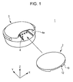
Fig. 1 illustrates the configuration of an example of an information processing system according to an exemplary embodiment of the present invention. - An
information processing system 1 includes theinformation bearing medium 2 having digital code assigned thereto and aninformation reading unit 3 that reads the digital code assigned to theinformation bearing medium 2. - The
information reading unit 3 includes amount unit 4 that allows theinformation bearing medium 2 to be mounted therein. Themount unit 4 has aninsertion port 4a that is open in a side surface of theinformation reading unit 3. Theinformation bearing medium 2 is inserted into themount unit 4 through theinsertion port 4a and is mounted in themount unit 4. Thereafter, theinformation reading unit 3 reads the digital code of theinformation bearing medium 2 mounted in themount unit 4. -
Fig. 2 illustrates the configuration of theinformation bearing medium 2. - The
information bearing medium 2 includes amedia substrate 10 and an array ofunit data zones 11. The array of theunit data zones 11 represents the digital code. Note that although themedia substrate 10 is a rigid plate-like member having a substantially circular shape in the example ofFig. 2 , the shape and the material of themedia substrate 10 are not limited thereto. - A
back surface 10a of themedia substrate 10 has agroove 12 formed therein. Thegroove 12 extends along any one of the diameters of themedia substrate 10, and both ends of thegroove 12 reach the side edge of themedia substrate 10. Thegroove 12 regulates a direction in which theinformation bearing medium 2 is inserted into themount unit 4 when theinformation bearing medium 2 is mounted in theinformation reading unit 3. - The array of the
unit data zones 11 is provided on the bottom surface of thegroove 12. The array of theunit data zones 11 is a two-dimensional array having a first direction and a second direction that is substantially perpendicular to the first direction. The second direction of the array of theunit data zones 11 is the same as the direction in which thegroove 12 extends. In the example illustrated inFig. 2 , the array of theunit data zones 11 is a 4-by-4 array. However, the number of theunit data zones 11 in each of the first direction and the second direction is not limited thereto. - Hereinafter, the first direction of the array of the
unit data zones 11 is referred to as an "X-direction", and the second direction is referred to as a "Y-direction". - Each of some of the
unit data zones 11 has amark 13 formed thereon. Themarks 13 are used to form the digital code. In the example illustrated inFig. 2 , themark 13 is configured in the form of a convex portion having a predetermined height. Binary data ("1" or "0") is assigned to each of theunit data zones 11 in accordance with the presence/absence of themark 13. In this manner, the array of theunit data zones 11 represents digital code. -
Figs. 3A and 3B illustrate an example of a mark pattern formed by the array of theunit data zones 11. More specifically,Fig. 3A illustrates a mark pattern using the physical layout of themarks 13, andFig. 3B illustrates the mark pattern using the digital code obtained by converting the presence/absence of themarks 13 into binary data "1" and "0". - Each of unit data zone
strings unit data zones 11 arranged in the X-direction includes at least onemark 13. - In addition, the mark patterns of any Y-direction adjacent two of the unit
data zone strings data zone string 14a based on the arrangement of marks in X-direction is "mark, no-mark, mark, mark", and the corresponding data string is "1, 0, 1, 1", while the mark pattern of the unitdata zone string 14b based on the arrangement of marks in X-direction is "no-mark, mark, mark, no-mark", and the corresponding data string is "0, 1, 1, 0". Thus, the two mark patterns differ from each other. - Furthermore, the mark pattern of the unit
data zone string 14d located at one end of the unitdata zone strings unit data zones 11. In the example illustrated inFigs. 2A and 2B , the mark pattern of the unitdata zone string 14d based on the arrangement of marks in the X-direction is "mark, no-mark, mark, no-mark", and a corresponding data string is "1, 0, 1, 0". - Hereinafter, the unit
data zone string 14d located at one end is referred to as a "terminal unit data zone string", and the unitdata zone string 14a located at the other end is referred to as a "beginning unit data zone string". - In addition, the mark pattern of the beginning unit
data zone string 14a based on the arrangement of marks in the X-direction differs from each of the mark patterns of the terminal unitdata zone string 14d based on the arrangements of marks in X-direction and the -X-direction. - Furthermore, the mark pattern of each of the unit data zone strings 14b and 14c based on the arrangement of marks in the X-direction differs from each of the mark patterns of the terminal unit
data zone string 14d based on the arrangements of marks in the X-direction and the -X-direction. - The
information bearing medium 2 is inserted into theinsertion port 4a of theinformation reading unit 3 with the beginning unitdata zone string 14a first and is mounted in themount unit 4. -
Fig. 4 illustrates an exemplary configuration of theinformation reading unit 3. - The
mount unit 4 of theinformation reading unit 3 has twoconvex ribs 20 formed thereon. The twoconvex ribs 20 are formed so as to extend in a direction parallel to the Y-direction of the array of theunit data zones 11 when theinformation bearing medium 2 is mounted in themount unit 4. Theconvex ribs 20 are engaged with the two side surfaces of thegroove 12 formed in themedia substrate 10. Thus, a direction in which theinformation bearing medium 2 is inserted into themount unit 4 is regulated to be the Y-direction. - In addition, the
mount unit 4 includes thedetection units 21 that detect themarks 13 formed in the array of theunit data zones 11 of theinformation bearing medium 2 and output a signal in accordance with the result of detection of themarks 13. The number of thedetection units 21 is the same as the number of theunit data zones 11 that constitute one unit data zone string. Thedetection units 21 are arranged between the twoconvex ribs 20 in a direction that is parallel to the X-direction of the array of theunit data zones 11 when theinformation bearing medium 2 is mounted in themount unit 4. - In the example illustrated in
Fig. 4 , thedetection units 21 are configured to serve as switches that can be depressed by themarks 13. When theinformation bearing medium 2 is inserted into themount unit 4 or is removed from themount unit 4 and, thus, themarks 13 pass over thedetection units 21, thedetection units 21 are depressed by themarks 13. After themark 13 pass by, thedetection units 21 automatically rise. When being depressed, each of thedetection units 21 outputs a signal of a High level. When thedetection unit 21 stays at a raised position, thedetection units 21 outputs a signal of a Low level. - When the
information bearing medium 2 is inserted into themount unit 4 or is removed from themount unit 4, the unitdata zone strings detection units 21 arranged in a line. Each time one of the unit data zone string passes over thedetection units 21 arranged in a line, the signals are output from the set of thedetection units 21 in synchronization. -
Fig. 5 is a functional block diagram of aninformation reading unit 3. - The
information reading unit 3 includes a processing unit that acquires a signal output from a group of thedetection units 21, recognizes the digital code of theinformation bearing medium 2, and performs a variety of processes and apower supply unit 22 that supplies electricity to all the units of theinformation reading unit 3. In addition, the processing unit includes an operatingunit 23, amemory unit 24, and acontrol unit 25. - The operating
unit 23 is configured so as to be capable of outputting audio and visual presentation including at least one of sound and emission of light. In the example illustrated inFig. 5 , the operatingunit 23 includes a speaker 26 so as to be capable of outputting representation based on sound. - Examples of the
memory unit 24 include a storage medium, such as a read only memory (ROM) and a random access memory (RAM). Thus, thememory unit 24 stores, for example, a program executed by thecontrol unit 25 and a table having a variety of digital codes assigned to the information bearing medium 2 in association with a variety of sound data items to be output to the operatingunit 23. - The
control unit 25 includes a processing unit (e.g., a microprocessor). Thus, thecontrol unit 25 operates in accordance with the program stored in thememory unit 24 and performs overall control of theinformation reading unit 3. - The
control unit 25 considers a group of signals output from a group of thedetection units 21 in synchronization as one unit. Thereafter, thecontrol unit 25 assigns digital data to each of the signals that constitute the unit signal group. By arranging the assigned digital data in accordance with the arrangement of thedetection units 21 in the X-direction, thecontrol unit 25 generates a data string. - In this example, each of the
detection units 21 outputs a High-level signal when it is depressed by one of themarks 13. When thedetection unit 21 stays in the raised position, thedetection unit 21 outputs a Low-level signal. Thecontrol unit 25 detects the signal level of a signal output from thedetection unit 21. If the signal level is High, thecontrol unit 25 assigns data "1" to the signal level. However, the signal level is Low, thecontrol unit 25 assigns data "0" to the signal level. Accordingly, if the mark pattern of the beginning unitdata zone string 14a based on the arrangement of marks in the X-direction is "mark, no-mark, mark, mark", a data string "1, 0, 1, 1" is generated (refer toFig. 3 ). - At that time, as described above, each of the unit
data zone strings mark 13. The mark patterns of any two adjacent unit data zone strings based on the arrangement of marks in the X-direction differ from each other. Accordingly, when the mark patterns of two adjacent unit data zone strings based on the arrangement of marks in the X-direction are detected by two group of thedetection units 21, at least one of the signals output from thedetection units 21 varies between the two adjacent unit data zone strings. - The
control unit 25 detects switching of a signal output from at least one of thedetection units 21. If a signal is switched, thecontrol unit 25 acquires the signals output from the group of thedetection units 21 in synchronization and generates a data string. In this manner, thecontrol unit 25 can accurately recognize a border between adjacent two of the unitdata zone strings detection units 21 and, thus, generate a data string for each of the unit data zone strings. - The
memory unit 24 reserves memory space for three data strings. Thecontrol unit 25 stores, in the memory space reserved in thememory unit 24, the data string sequentially acquired for each of the unit data zone strings when theinformation bearing medium 2 is inserted into themount unit 4. For example, theinformation bearing medium 2 is inserted into themount unit 4 with the beginning unitdata zone string 14a first, three data strings sequentially acquired from the unitdata zone strings memory unit 24. - Subsequently, if the
control unit 25 detects a data string "1, 0, 1, 0" corresponding to the particular mark pattern "mark, no-mark, mark, no-mark" of the terminal unitdata zone string 14d based on the arrangement of marks in the X-direction, thecontrol unit 25 recognizes the digital code on the basis of the data strings stored in thememory unit 24 and performs a process corresponding to the recognized digital code. - Hereinafter, the pattern of the data string "1, 0, 1, 0", which corresponds to the above-described particular mark pattern "mark, no-mark, mark, no-mark", is referred to as an "end data string pattern", and a mark pattern "no-mark, mark, no-mark, mark" obtained by reversing the particular mark pattern is referred to as an "reverse particular mark pattern". In addition, a pattern of the data string "0, 1, 0, 1" corresponding to the reverse particular mark pattern is referred to as an "reverse end data string pattern".
-
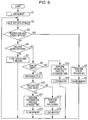
Fig. 6 illustrates the flow of a process performed by thecontrol unit 25. - If the
information reading unit 3 is powered ON, thecontrol unit 25 reserves memory space for three data strings in thememory unit 24 and clears data in the memory space (step S1). - If the
information bearing medium 2 is inserted into themount unit 4 or is removed from themount unit 4, signals are output from a group of thedetection units 21 that detect the mark pattern of each of the unit data zone strings. Thecontrol unit 25 acquires the signals output from the group of thedetection units 21 and generates a data string (step S2). - Subsequently, the
control unit 25 determines whether the data string matches the above-described reverse end data string pattern (step S3). - For example, if the
information bearing medium 2 is inserted into themount unit 4 with the beginning unitdata zone string 14a first, the mark pattern of the beginning unitdata zone string 14a based on the arrangement of marks in the X-direction is detected by the group of thedetection units 21 first. The mark pattern differs from the above-described reverse particular mark pattern and, thus, the data string differs from the above-described reverse end data string pattern. - In contrast, if the
information bearing medium 2 is inserted into themount unit 4 with the terminal unitdata zone string 14d first, the mark pattern of the terminal unitdata zone string 14d based on the arrangement of marks in the X-direction is detected by the group of thedetection units 21 first. The mark pattern matches the reverse particular mark pattern and, thus, the data string matches the reverse end data string pattern. - Accordingly, if the data string matches the reverse end data string pattern, the
control unit 25 determines that theinformation bearing medium 2 is mounted in themount unit 4 the other way around. Thus, thecontrol unit 25 performs error processing (step S4) and clears the data in the memory space reserved in the memory unit 24 (step S5). Examples of the error processing include a process to activate the operatingunit 23 on the basis of audio data, such as an error message, stored in thememory unit 24. - However, if the data string does not match the reverse end data string pattern, the
control unit 25 determines whether the data string matches the above-described end data string pattern (step S6). - In addition, if the data string does not match the end data string pattern, the
control unit 25 stores the data string in the memory space reserved in the memory unit 24 (step S7). - For example, if the
information bearing medium 2 is inserted into themount unit 4 with the beginning unitdata zone string 14a first, the mark patterns of the unitdata zone strings detection units 21. At that time, each of the mark patterns of the unitdata zone strings data zone strings data zone strings memory unit 24. - However, if the data string matches the end data string pattern, the
control unit 25 determines whether the memory space reserved in thememory unit 24 is empty (step S8). If the memory space is not empty, that is, if a data string is stored in the memory space, thecontrol unit 25 recognizes the digital code on the basis of the data string stored in the memory space (step S9). Thereafter, thecontrol unit 25 determines whether the digital code is valid on the basis of whether the digital code is contained in a table stored in the memory unit 24 (step S10). - For example, when the
information bearing medium 2 is inserted into themount unit 4 with the beginning unitdata zone string 14a first and, thus, the data strings sequentially obtained from the unitdata zone strings memory unit 24 and if mounting of the information bearing medium 2 in themount unit 4 is completed, the end data string pattern is detected in the data string obtained from the terminal unitdata zone string 14d. At that time, the data strings obtained from the unitdata zone strings memory unit 24. Thus, the digital code is recognized on the basis of these data strings. The digital code is contained in the table in thememory unit 24 as one of the digital codes assigned to theinformation bearing medium 2. Thus, the digital code is determined to be valid. - If the digital code is valid, the
control unit 25 performs an audio and visual presentation process when theinformation bearing medium 2 is mounted in themount unit 4. In the audio and visual presentation process, thecontrol unit 25 reads, from thememory unit 24, audio data stored in association with the digital code and activates the operatingunit 23 to operate on the basis of the read audio data (step S11). In addition, thecontrol unit 25 clears the data in the memory space reserved in the memory unit 24 (step S12). - However, if the recognized digital code is not valid, the
control unit 25 performs error processing (step S13) and clears the data in the memory space reserved in the memory unit 24 (step S14). - For example, the digital code is not valid if the
information bearing medium 2 is moved back and forth during insertion of the information bearing medium 2 into themount unit 4. At that time, the beginning unitdata zone string 14a or the unitdata zone string 14b are detected by the group of the detection units 21 a plurality of times and, thus, the data strings obtained from the beginning unitdata zone string 14a and the unitdata zone string 14b are duplicately stored in the memory space reserved in thememory unit 24. - If, after the
information bearing medium 2 is mounted in themount unit 4 and the presentation process at the time of mounting (step S11) or the error process (step S13) is performed, theinformation bearing medium 2 is removed from themount unit 4, the mark pattern of the terminal unitdata zone string 14d based on the arrangement of parks in the X-direction is detected by the group of thedetection units 21 first. The end data string pattern is detected in the data string obtained from the terminal unitdata zone string 14d. At that time, data in the memory space reserved in thememory unit 24 is cleared and, therefore, the memory space is empty (step S12 or S14). - As described above, when the data string matches the end data string pattern and if the memory space is empty, the
control unit 25 performs a presentation process for removal of the information bearing medium 2 from the mount unit 4 (step S15) and clears data in the memory space reserved in the memory unit 24 (step S16). Examples of the presentation process for removal of theinformation bearing medium 2 includes a process to activate the operatingunit 23 to operate on the basis of audio data, such as sound effects, stored in thememory unit 24. - Note that the above-described presentation process for removal of the
information bearing medium 2 is also performed if theinformation bearing medium 2 is removed from themount unit 4 after theinformation reading unit 3 is powered ON with the information bearing medium 2 mounted in themount unit 4.
Claims (11)
- An information bearing medium (2) comprising:a media substrate (10); anda plurality of unit data zones (11),wherein a mark (13) is provided on each of some of the unit data zones (11) so as to form a digital code,wherein the mark (13) is a convex portion having a predetermined height formed on a surface of the media substrate (10) and the presence or absence of the convex portion provides binary data for the unit data zones;characterised in that:the unit data zones (11) are formed on the media substrate (10) in an array having a first direction and a second direction that crosses the first direction,the array is formed from unit data zone strings (14a, 14b, 14c, 14d) each extending in the first direction, andmark patterns of any second-directional adjacent two of the unit data zone strings (14a, 14b, 14c, 14d) based on an arrangement of marks (13) in the first direction differ from each other, and/ora mark pattern based on the arrangement of marks (13) in the first direction of a beginning unit data zone string (14a) at one end of the array of unit data zones (11) in the second direction differs from each of the mark patterns based on the arrangement of marks (13) in the first direction and a direction opposite to the first direction of a terminal unit data zone string (14d) at the other end of the array of unit data zones (11) in the second direction.
- The information bearing medium according to Claim 1, wherein each of the unit data zone strings (14a, 14b, 14c, 14d) includes at least one mark (13).
- The information bearing medium according to Claim 1 or 2, wherein the mark pattern of the unit data zone string other than the beginning unit data zone string (14a) and the terminal unit data zone string (14d) based on the arrangement of marks (13) in the first direction differs from the mark pattern of the terminal unit data zone string based on the arrangement of marks (13) in the first direction.
- The information bearing medium according to any one of Claims 1 to 3, further comprising:a guided portion (12) provided on the media substrate (10), the guided portion (12) extending in the second direction.
- The information bearing medium according to Claim 4, wherein the guided portion (12) is in the form of a groove, and
wherein the unit data zones (11) are formed in the groove. - An information processing system comprising:the information bearing medium (2) according to any one of Claims 1 to 5; andan information reading unit (3) configured to read a digital code formed by the array of the unit data zones (11) of the information bearing medium (2),wherein the information reading unit (3) includes a mount unit (4) configured to allow the information bearing medium (2) to move relative thereto in the second direction and be mounted therein, a plurality of detection units (21) that are provided in the mount unit (4) so as to be arranged in a direction parallel to the first direction of the information bearing medium (2) and that are configured to detect the marks (13) provided on the unit data zones (11) of the information bearing medium (2) and output signals corresponding to a result of detection, and a processing unit (25) configured to generate a data string on the basis of a unit signal formed from the plurality of signals output from the detection units (21) in synchronization and recognize the digital code on the basis of a group of the data strings sequentially obtained from the array of the unit data zones (11) of the information bearing medium (2), wherein each of the detection units (21) is a switch configured to be depressed by the convex portion.
- The information processing system according to Claim 6:wherein the mark pattern of a terminal unit data zone string of the information bearing medium based on the arrangement of marks (13) in the first direction is a particular mark pattern,wherein upon detecting a particular data string obtained from the particular mark pattern, the processing unit (25) is configured to perform a process to recognize the digital code, andwherein upon detecting a reverse particular data string obtained from a reverse particular mark pattern generated by reversing the particular mark pattern in a direction opposite to the first direction, the processing unit (25) is configured to perform an error process.
- The information processing system according to Claim 6 or 7, wherein the information bearing medium (2) further includes a guided portion (12) that is provided on the media substrate (10) and that extends in the second direction, and
wherein the mount unit (4) of the information reading unit (3) has a guiding portion (20) that is configured to be engaged with the guided portion (12) of the information bearing medium (2) so as to guide movement of the information bearing medium (2) relative to the mount unit (4) in the second direction. - The information processing system according to Claim 8, wherein the guided portion (12) of the information bearing medium (2) is in the form of a groove, and
wherein the guiding portion (20) of the information reading unit (3) is in the form of a convex rib extending in a direction parallel to the second direction of the information bearing medium (2). - The information processing system according to any one of Claims 7 to 10, wherein the information reading unit (3) further includes an operating unit (23) and a storage unit (24) configured to store operation data used for operating the operating unit (23) in association with the digital code, and
wherein the processing unit (25) of the information reading unit (3) is configured to read the operation data corresponding to the recognized digital code out of the storage unit (24) and cause the operating unit (23) to operate on the basis of the readout operation data. - The information processing system according to Claim 10, wherein the operating unit (23) is capable of outputting presentation including at least one of sound and light emission.
Applications Claiming Priority (1)
| Application Number | Priority Date | Filing Date | Title |
|---|---|---|---|
| JP2013137161A JP5583826B1 (en) | 2013-06-28 | 2013-06-28 | Information holding medium and information processing system |
Publications (2)
| Publication Number | Publication Date |
|---|---|
| EP2819066A1 EP2819066A1 (en) | 2014-12-31 |
| EP2819066B1 true EP2819066B1 (en) | 2016-02-24 |
Family
ID=50900657
Family Applications (1)
| Application Number | Title | Priority Date | Filing Date |
|---|---|---|---|
| EP14168170.0A Active EP2819066B1 (en) | 2013-06-28 | 2014-05-13 | Information bearing medium and information processing system |
Country Status (6)
| Country | Link |
|---|---|
| US (9) | US9495565B2 (en) |
| EP (1) | EP2819066B1 (en) |
| JP (2) | JP5583826B1 (en) |
| KR (1) | KR101579677B1 (en) |
| CN (3) | CN103861283B (en) |
| TW (1) | TWI526941B (en) |
Families Citing this family (15)
| Publication number | Priority date | Publication date | Assignee | Title |
|---|---|---|---|---|
| JP5583826B1 (en) * | 2013-06-28 | 2014-09-03 | 株式会社バンダイ | Information holding medium and information processing system |
| JP1516643S (en) * | 2014-04-01 | 2015-02-02 | ||
| TWD170210S (en) * | 2014-04-01 | 2015-09-01 | 萬代股份有限公司 | Part of a disk-shaped toy |
| JP5785651B1 (en) * | 2014-11-20 | 2015-09-30 | 株式会社バンダイ | Article discharge device |
| JP6327195B2 (en) * | 2015-04-27 | 2018-05-23 | 株式会社デンソー | Control device |
| JP1552685S (en) * | 2015-09-02 | 2016-06-27 | ||
| JP1552684S (en) * | 2015-09-02 | 2016-06-27 | ||
| JP1555311S (en) * | 2016-03-17 | 2016-08-01 | ||
| USD816289S1 (en) * | 2016-11-04 | 2018-04-24 | Robert G. Capurso | Grave marker medallion |
| USD805716S1 (en) * | 2016-11-04 | 2017-12-19 | Robert G. Capurso | Grave marker medallion |
| JP6660916B2 (en) * | 2017-05-31 | 2020-03-11 | 株式会社バンダイ | Direction output toys |
| JP6688766B2 (en) * | 2017-06-29 | 2020-04-28 | 株式会社バンダイ | Information processing device and system |
| JP6626181B1 (en) * | 2018-11-13 | 2019-12-25 | 株式会社バンダイ | Production output toy, production output toy set, and operation tool for production output toy |
| JP7296445B2 (en) * | 2020-07-20 | 2023-06-22 | 株式会社バンダイ | toy |
| JP7002609B2 (en) * | 2020-07-20 | 2022-01-20 | 株式会社バンダイ | toy |
Family Cites Families (18)
| Publication number | Priority date | Publication date | Assignee | Title |
|---|---|---|---|---|
| US5304786A (en) * | 1990-01-05 | 1994-04-19 | Symbol Technologies, Inc. | High density two-dimensional bar code symbol |
| US5451178A (en) * | 1992-03-26 | 1995-09-19 | Sony Corporation | Auditory playing device |
| JPH07134757A (en) * | 1993-11-09 | 1995-05-23 | Toppan Printing Co Ltd | Display body provided with two-dimensional code and two-dimensional code reader |
| JPH09160998A (en) * | 1995-12-13 | 1997-06-20 | Hitachi Metals Ltd | Method for discriminating container information |
| JPH11185245A (en) * | 1997-12-17 | 1999-07-09 | Oji Paper Co Ltd | Magnetic recording medium and production of magnetic recording medium |
| JP2005100014A (en) * | 2003-09-24 | 2005-04-14 | Miyota Kk | Id plate and collating device using the same |
| US7164646B2 (en) * | 2004-02-19 | 2007-01-16 | Hewlett-Packard Development Company, L.P. | Storage device having a storage cell programmable to one of more than two storage states |
| CN1991862A (en) * | 2005-12-29 | 2007-07-04 | 边鹏 | Two-dimensional bar-shaped system with high reliability and recognizing method thereof |
| JP2009537030A (en) * | 2006-05-11 | 2009-10-22 | ビルケア テクノロジーズ プライベート リミテッド | Identification tag, object configured to be identified, associated method, device, and system |
| US7477853B2 (en) * | 2006-07-26 | 2009-01-13 | Kabushiki Kaisha Toshiba | Toner cartridge having machine readable authentication pattern and image forming apparatus for reading the same |
| JP4267019B2 (en) | 2006-10-13 | 2009-05-27 | 株式会社コナミデジタルエンタテインメント | Card identification device, card identification method, and program |
| US8521291B1 (en) * | 2006-10-31 | 2013-08-27 | Pacesetter, Inc. | Dual therapy electrical stimulation system for treating metabolic and eating disorders |
| JP4384253B1 (en) | 2009-03-19 | 2009-12-16 | 株式会社バンダイ | Game device |
| US8251291B2 (en) * | 2009-04-01 | 2012-08-28 | Honeywell International Inc. | Rotational bar code orientation sensor |
| JP2011103032A (en) * | 2009-11-10 | 2011-05-26 | B-Core Inc | Optical automatic recognition code including three-dimensional shape areas |
| US8893978B2 (en) | 2011-03-14 | 2014-11-25 | Ping Cheung Michael LAU | Surface identification system and method, object having an identification code pattern, and code reading apparatus for reading the object |
| WO2013036056A2 (en) * | 2011-09-06 | 2013-03-14 | 쓰리웨이테크놀러지(주) | Security medium and authentication system using same |
| JP5583826B1 (en) | 2013-06-28 | 2014-09-03 | 株式会社バンダイ | Information holding medium and information processing system |
-
2013
- 2013-06-28 JP JP2013137161A patent/JP5583826B1/en active Active
-
2014
- 2014-03-13 TW TW103109145A patent/TWI526941B/en active
- 2014-03-20 KR KR1020140032654A patent/KR101579677B1/en active IP Right Grant
- 2014-03-26 CN CN201410117541.2A patent/CN103861283B/en active Active
- 2014-03-26 CN CN201710161247.5A patent/CN106897755B/en active Active
- 2014-03-26 CN CN201710762228.8A patent/CN107766759B/en active Active
- 2014-04-15 JP JP2014083332A patent/JP6155221B2/en active Active
- 2014-05-13 EP EP14168170.0A patent/EP2819066B1/en active Active
- 2014-05-22 US US14/285,187 patent/US9495565B2/en active Active
- 2014-09-29 US US14/500,536 patent/US9202090B2/en active Active
-
2016
- 2016-11-11 US US15/349,335 patent/US9798905B2/en active Active
-
2017
- 2017-09-21 US US15/711,344 patent/US10013586B2/en active Active
-
2018
- 2018-05-31 US US15/993,803 patent/US10210354B2/en active Active
-
2019
- 2019-01-08 US US16/242,369 patent/US10528773B2/en active Active
- 2019-12-04 US US16/703,630 patent/US10747965B2/en active Active
-
2020
- 2020-07-14 US US16/928,429 patent/US11250223B2/en active Active
-
2022
- 2022-01-05 US US17/568,914 patent/US20220129647A1/en not_active Abandoned
Also Published As
| Publication number | Publication date |
|---|---|
| TW201501040A (en) | 2015-01-01 |
| EP2819066A1 (en) | 2014-12-31 |
| US20200342185A1 (en) | 2020-10-29 |
| US20200104551A1 (en) | 2020-04-02 |
| US10528773B2 (en) | 2020-01-07 |
| CN107766759A (en) | 2018-03-06 |
| KR20150003089A (en) | 2015-01-08 |
| US20180018480A1 (en) | 2018-01-18 |
| US11250223B2 (en) | 2022-02-15 |
| CN106897755A (en) | 2017-06-27 |
| CN103861283A (en) | 2014-06-18 |
| CN107766759B (en) | 2021-09-10 |
| US20180276423A1 (en) | 2018-09-27 |
| US9798905B2 (en) | 2017-10-24 |
| TWI526941B (en) | 2016-03-21 |
| US20150001286A1 (en) | 2015-01-01 |
| US10747965B2 (en) | 2020-08-18 |
| JP2015011564A (en) | 2015-01-19 |
| US20150014410A1 (en) | 2015-01-15 |
| KR101579677B1 (en) | 2016-01-04 |
| US20190138759A1 (en) | 2019-05-09 |
| US20170061169A1 (en) | 2017-03-02 |
| CN106897755B (en) | 2021-03-12 |
| US9202090B2 (en) | 2015-12-01 |
| US20220129647A1 (en) | 2022-04-28 |
| US10210354B2 (en) | 2019-02-19 |
| US9495565B2 (en) | 2016-11-15 |
| US10013586B2 (en) | 2018-07-03 |
| JP5583826B1 (en) | 2014-09-03 |
| CN103861283B (en) | 2017-09-29 |
| JP2015011705A (en) | 2015-01-19 |
| JP6155221B2 (en) | 2017-06-28 |
Similar Documents
| Publication | Publication Date | Title |
|---|---|---|
| EP2819066B1 (en) | Information bearing medium and information processing system | |
| KR101810847B1 (en) | Information storage medium and information reading device | |
| AU2014233569B2 (en) | Information bearing medium and information processing system | |
| JP6526884B2 (en) | Information holding medium and information processing system | |
| JP7179798B2 (en) | Information processing system | |
| JP7462603B2 (en) | Performance output system | |
| JP6686211B2 (en) | Information storage medium and information processing system | |
| JP2016012355A (en) | Information holding medium and information reading device | |
| JP6133225B2 (en) | Card processing system |
Legal Events
| Date | Code | Title | Description |
|---|---|---|---|
| PUAI | Public reference made under article 153(3) epc to a published international application that has entered the european phase |
Free format text: ORIGINAL CODE: 0009012 |
|
| 17P | Request for examination filed |
Effective date: 20140513 |
|
| AK | Designated contracting states |
Kind code of ref document: A1 Designated state(s): AL AT BE BG CH CY CZ DE DK EE ES FI FR GB GR HR HU IE IS IT LI LT LU LV MC MK MT NL NO PL PT RO RS SE SI SK SM TR |
|
| AX | Request for extension of the european patent |
Extension state: BA ME |
|
| REG | Reference to a national code |
Ref country code: DE Ref legal event code: R079 Ref document number: 602014000947 Country of ref document: DE Free format text: PREVIOUS MAIN CLASS: G06K0019060000 Ipc: G06K0005000000 |
|
| GRAP | Despatch of communication of intention to grant a patent |
Free format text: ORIGINAL CODE: EPIDOSNIGR1 |
|
| RIC1 | Information provided on ipc code assigned before grant |
Ipc: G06K 5/00 20060101AFI20150821BHEP Ipc: G06K 19/063 20060101ALI20150821BHEP Ipc: G06K 7/00 20060101ALI20150821BHEP Ipc: G06K 7/04 20060101ALI20150821BHEP Ipc: G06K 19/04 20060101ALI20150821BHEP Ipc: G06K 19/06 20060101ALI20150821BHEP |
|
| INTG | Intention to grant announced |
Effective date: 20150909 |
|
| GRAS | Grant fee paid |
Free format text: ORIGINAL CODE: EPIDOSNIGR3 |
|
| GRAA | (expected) grant |
Free format text: ORIGINAL CODE: 0009210 |
|
| AK | Designated contracting states |
Kind code of ref document: B1 Designated state(s): AL AT BE BG CH CY CZ DE DK EE ES FI FR GB GR HR HU IE IS IT LI LT LU LV MC MK MT NL NO PL PT RO RS SE SI SK SM TR |
|
| REG | Reference to a national code |
Ref country code: GB Ref legal event code: FG4D |
|
| REG | Reference to a national code |
Ref country code: CH Ref legal event code: EP |
|
| REG | Reference to a national code |
Ref country code: AT Ref legal event code: REF Ref document number: 777064 Country of ref document: AT Kind code of ref document: T Effective date: 20160315 |
|
| REG | Reference to a national code |
Ref country code: IE Ref legal event code: FG4D |
|
| REG | Reference to a national code |
Ref country code: DE Ref legal event code: R096 Ref document number: 602014000947 Country of ref document: DE |
|
| REG | Reference to a national code |
Ref country code: FR Ref legal event code: PLFP Year of fee payment: 3 |
|
| REG | Reference to a national code |
Ref country code: LT Ref legal event code: MG4D |
|
| REG | Reference to a national code |
Ref country code: NL Ref legal event code: MP Effective date: 20160224 |
|
| REG | Reference to a national code |
Ref country code: AT Ref legal event code: MK05 Ref document number: 777064 Country of ref document: AT Kind code of ref document: T Effective date: 20160224 |
|
| PG25 | Lapsed in a contracting state [announced via postgrant information from national office to epo] |
Ref country code: HR Free format text: LAPSE BECAUSE OF FAILURE TO SUBMIT A TRANSLATION OF THE DESCRIPTION OR TO PAY THE FEE WITHIN THE PRESCRIBED TIME-LIMIT Effective date: 20160224 Ref country code: GR Free format text: LAPSE BECAUSE OF FAILURE TO SUBMIT A TRANSLATION OF THE DESCRIPTION OR TO PAY THE FEE WITHIN THE PRESCRIBED TIME-LIMIT Effective date: 20160525 Ref country code: NO Free format text: LAPSE BECAUSE OF FAILURE TO SUBMIT A TRANSLATION OF THE DESCRIPTION OR TO PAY THE FEE WITHIN THE PRESCRIBED TIME-LIMIT Effective date: 20160524 Ref country code: ES Free format text: LAPSE BECAUSE OF FAILURE TO SUBMIT A TRANSLATION OF THE DESCRIPTION OR TO PAY THE FEE WITHIN THE PRESCRIBED TIME-LIMIT Effective date: 20160224 Ref country code: FI Free format text: LAPSE BECAUSE OF FAILURE TO SUBMIT A TRANSLATION OF THE DESCRIPTION OR TO PAY THE FEE WITHIN THE PRESCRIBED TIME-LIMIT Effective date: 20160224 |
|
| PG25 | Lapsed in a contracting state [announced via postgrant information from national office to epo] |
Ref country code: NL Free format text: LAPSE BECAUSE OF FAILURE TO SUBMIT A TRANSLATION OF THE DESCRIPTION OR TO PAY THE FEE WITHIN THE PRESCRIBED TIME-LIMIT Effective date: 20160224 Ref country code: RS Free format text: LAPSE BECAUSE OF FAILURE TO SUBMIT A TRANSLATION OF THE DESCRIPTION OR TO PAY THE FEE WITHIN THE PRESCRIBED TIME-LIMIT Effective date: 20160224 Ref country code: LV Free format text: LAPSE BECAUSE OF FAILURE TO SUBMIT A TRANSLATION OF THE DESCRIPTION OR TO PAY THE FEE WITHIN THE PRESCRIBED TIME-LIMIT Effective date: 20160224 Ref country code: SE Free format text: LAPSE BECAUSE OF FAILURE TO SUBMIT A TRANSLATION OF THE DESCRIPTION OR TO PAY THE FEE WITHIN THE PRESCRIBED TIME-LIMIT Effective date: 20160224 Ref country code: AT Free format text: LAPSE BECAUSE OF FAILURE TO SUBMIT A TRANSLATION OF THE DESCRIPTION OR TO PAY THE FEE WITHIN THE PRESCRIBED TIME-LIMIT Effective date: 20160224 Ref country code: LT Free format text: LAPSE BECAUSE OF FAILURE TO SUBMIT A TRANSLATION OF THE DESCRIPTION OR TO PAY THE FEE WITHIN THE PRESCRIBED TIME-LIMIT Effective date: 20160224 Ref country code: PL Free format text: LAPSE BECAUSE OF FAILURE TO SUBMIT A TRANSLATION OF THE DESCRIPTION OR TO PAY THE FEE WITHIN THE PRESCRIBED TIME-LIMIT Effective date: 20160224 Ref country code: BE Free format text: LAPSE BECAUSE OF NON-PAYMENT OF DUE FEES Effective date: 20160531 Ref country code: PT Free format text: LAPSE BECAUSE OF FAILURE TO SUBMIT A TRANSLATION OF THE DESCRIPTION OR TO PAY THE FEE WITHIN THE PRESCRIBED TIME-LIMIT Effective date: 20160624 |
|
| PG25 | Lapsed in a contracting state [announced via postgrant information from national office to epo] |
Ref country code: EE Free format text: LAPSE BECAUSE OF FAILURE TO SUBMIT A TRANSLATION OF THE DESCRIPTION OR TO PAY THE FEE WITHIN THE PRESCRIBED TIME-LIMIT Effective date: 20160224 Ref country code: DK Free format text: LAPSE BECAUSE OF FAILURE TO SUBMIT A TRANSLATION OF THE DESCRIPTION OR TO PAY THE FEE WITHIN THE PRESCRIBED TIME-LIMIT Effective date: 20160224 |
|
| REG | Reference to a national code |
Ref country code: DE Ref legal event code: R097 Ref document number: 602014000947 Country of ref document: DE |
|
| PG25 | Lapsed in a contracting state [announced via postgrant information from national office to epo] |
Ref country code: SK Free format text: LAPSE BECAUSE OF FAILURE TO SUBMIT A TRANSLATION OF THE DESCRIPTION OR TO PAY THE FEE WITHIN THE PRESCRIBED TIME-LIMIT Effective date: 20160224 Ref country code: CZ Free format text: LAPSE BECAUSE OF FAILURE TO SUBMIT A TRANSLATION OF THE DESCRIPTION OR TO PAY THE FEE WITHIN THE PRESCRIBED TIME-LIMIT Effective date: 20160224 Ref country code: SM Free format text: LAPSE BECAUSE OF FAILURE TO SUBMIT A TRANSLATION OF THE DESCRIPTION OR TO PAY THE FEE WITHIN THE PRESCRIBED TIME-LIMIT Effective date: 20160224 Ref country code: RO Free format text: LAPSE BECAUSE OF FAILURE TO SUBMIT A TRANSLATION OF THE DESCRIPTION OR TO PAY THE FEE WITHIN THE PRESCRIBED TIME-LIMIT Effective date: 20160224 |
|
| REG | Reference to a national code |
Ref country code: DE Ref legal event code: R119 Ref document number: 602014000947 Country of ref document: DE |
|
| PG25 | Lapsed in a contracting state [announced via postgrant information from national office to epo] |
Ref country code: LU Free format text: LAPSE BECAUSE OF FAILURE TO SUBMIT A TRANSLATION OF THE DESCRIPTION OR TO PAY THE FEE WITHIN THE PRESCRIBED TIME-LIMIT Effective date: 20160513 Ref country code: BE Free format text: LAPSE BECAUSE OF FAILURE TO SUBMIT A TRANSLATION OF THE DESCRIPTION OR TO PAY THE FEE WITHIN THE PRESCRIBED TIME-LIMIT Effective date: 20160224 |
|
| PLBE | No opposition filed within time limit |
Free format text: ORIGINAL CODE: 0009261 |
|
| STAA | Information on the status of an ep patent application or granted ep patent |
Free format text: STATUS: NO OPPOSITION FILED WITHIN TIME LIMIT |
|
| 26N | No opposition filed |
Effective date: 20161125 |
|
| REG | Reference to a national code |
Ref country code: IE Ref legal event code: MM4A |
|
| PG25 | Lapsed in a contracting state [announced via postgrant information from national office to epo] |
Ref country code: SI Free format text: LAPSE BECAUSE OF FAILURE TO SUBMIT A TRANSLATION OF THE DESCRIPTION OR TO PAY THE FEE WITHIN THE PRESCRIBED TIME-LIMIT Effective date: 20160224 Ref country code: BG Free format text: LAPSE BECAUSE OF FAILURE TO SUBMIT A TRANSLATION OF THE DESCRIPTION OR TO PAY THE FEE WITHIN THE PRESCRIBED TIME-LIMIT Effective date: 20160524 |
|
| REG | Reference to a national code |
Ref country code: FR Ref legal event code: PLFP Year of fee payment: 4 |
|
| PG25 | Lapsed in a contracting state [announced via postgrant information from national office to epo] |
Ref country code: DE Free format text: LAPSE BECAUSE OF NON-PAYMENT OF DUE FEES Effective date: 20161201 |
|
| PG25 | Lapsed in a contracting state [announced via postgrant information from national office to epo] |
Ref country code: IE Free format text: LAPSE BECAUSE OF NON-PAYMENT OF DUE FEES Effective date: 20160513 |
|
| REG | Reference to a national code |
Ref country code: CH Ref legal event code: PL |
|
| PG25 | Lapsed in a contracting state [announced via postgrant information from national office to epo] |
Ref country code: LI Free format text: LAPSE BECAUSE OF NON-PAYMENT OF DUE FEES Effective date: 20170531 Ref country code: CH Free format text: LAPSE BECAUSE OF NON-PAYMENT OF DUE FEES Effective date: 20170531 |
|
| REG | Reference to a national code |
Ref country code: FR Ref legal event code: PLFP Year of fee payment: 5 |
|
| PG25 | Lapsed in a contracting state [announced via postgrant information from national office to epo] |
Ref country code: HU Free format text: LAPSE BECAUSE OF FAILURE TO SUBMIT A TRANSLATION OF THE DESCRIPTION OR TO PAY THE FEE WITHIN THE PRESCRIBED TIME-LIMIT; INVALID AB INITIO Effective date: 20140513 |
|
| PG25 | Lapsed in a contracting state [announced via postgrant information from national office to epo] |
Ref country code: MC Free format text: LAPSE BECAUSE OF FAILURE TO SUBMIT A TRANSLATION OF THE DESCRIPTION OR TO PAY THE FEE WITHIN THE PRESCRIBED TIME-LIMIT Effective date: 20160224 Ref country code: MK Free format text: LAPSE BECAUSE OF FAILURE TO SUBMIT A TRANSLATION OF THE DESCRIPTION OR TO PAY THE FEE WITHIN THE PRESCRIBED TIME-LIMIT Effective date: 20160224 Ref country code: MT Free format text: LAPSE BECAUSE OF NON-PAYMENT OF DUE FEES Effective date: 20160531 Ref country code: IS Free format text: LAPSE BECAUSE OF FAILURE TO SUBMIT A TRANSLATION OF THE DESCRIPTION OR TO PAY THE FEE WITHIN THE PRESCRIBED TIME-LIMIT Effective date: 20160224 Ref country code: CY Free format text: LAPSE BECAUSE OF FAILURE TO SUBMIT A TRANSLATION OF THE DESCRIPTION OR TO PAY THE FEE WITHIN THE PRESCRIBED TIME-LIMIT Effective date: 20160224 |
|
| PG25 | Lapsed in a contracting state [announced via postgrant information from national office to epo] |
Ref country code: AL Free format text: LAPSE BECAUSE OF FAILURE TO SUBMIT A TRANSLATION OF THE DESCRIPTION OR TO PAY THE FEE WITHIN THE PRESCRIBED TIME-LIMIT Effective date: 20160224 Ref country code: TR Free format text: LAPSE BECAUSE OF FAILURE TO SUBMIT A TRANSLATION OF THE DESCRIPTION OR TO PAY THE FEE WITHIN THE PRESCRIBED TIME-LIMIT Effective date: 20160224 |
|
| REG | Reference to a national code |
Ref country code: FR Ref legal event code: PLFP Year of fee payment: 10 |
|
| PGFP | Annual fee paid to national office [announced via postgrant information from national office to epo] |
Ref country code: GB Payment date: 20230330 Year of fee payment: 10 |
|
| PGFP | Annual fee paid to national office [announced via postgrant information from national office to epo] |
Ref country code: IT Payment date: 20230412 Year of fee payment: 10 Ref country code: FR Payment date: 20230411 Year of fee payment: 10 |