EP2818950A2 - Apparatus for changing a parameter of a machining device using a graphical user interface - Google Patents
Apparatus for changing a parameter of a machining device using a graphical user interface Download PDFInfo
- Publication number
- EP2818950A2 EP2818950A2 EP14172175.3A EP14172175A EP2818950A2 EP 2818950 A2 EP2818950 A2 EP 2818950A2 EP 14172175 A EP14172175 A EP 14172175A EP 2818950 A2 EP2818950 A2 EP 2818950A2
- Authority
- EP
- European Patent Office
- Prior art keywords
- parameter value
- processing
- user interface
- graphical user
- change
- Prior art date
- Legal status (The legal status is an assumption and is not a legal conclusion. Google has not performed a legal analysis and makes no representation as to the accuracy of the status listed.)
- Withdrawn
Links
Images


Classifications
-
- G—PHYSICS
- G05—CONTROLLING; REGULATING
- G05B—CONTROL OR REGULATING SYSTEMS IN GENERAL; FUNCTIONAL ELEMENTS OF SUCH SYSTEMS; MONITORING OR TESTING ARRANGEMENTS FOR SUCH SYSTEMS OR ELEMENTS
- G05B19/00—Programme-control systems
- G05B19/02—Programme-control systems electric
- G05B19/18—Numerical control [NC], i.e. automatically operating machines, in particular machine tools, e.g. in a manufacturing environment, so as to execute positioning, movement or co-ordinated operations by means of programme data in numerical form
- G05B19/4093—Numerical control [NC], i.e. automatically operating machines, in particular machine tools, e.g. in a manufacturing environment, so as to execute positioning, movement or co-ordinated operations by means of programme data in numerical form characterised by part programming, e.g. entry of geometrical information as taken from a technical drawing, combining this with machining and material information to obtain control information, named part programme, for the NC machine
- G05B19/40937—Numerical control [NC], i.e. automatically operating machines, in particular machine tools, e.g. in a manufacturing environment, so as to execute positioning, movement or co-ordinated operations by means of programme data in numerical form characterised by part programming, e.g. entry of geometrical information as taken from a technical drawing, combining this with machining and material information to obtain control information, named part programme, for the NC machine concerning programming of machining or material parameters, pocket machining
-
- G—PHYSICS
- G05—CONTROLLING; REGULATING
- G05B—CONTROL OR REGULATING SYSTEMS IN GENERAL; FUNCTIONAL ELEMENTS OF SUCH SYSTEMS; MONITORING OR TESTING ARRANGEMENTS FOR SUCH SYSTEMS OR ELEMENTS
- G05B2219/00—Program-control systems
- G05B2219/30—Nc systems
- G05B2219/32—Operator till task planning
- G05B2219/32128—Gui graphical user interface
-
- G—PHYSICS
- G05—CONTROLLING; REGULATING
- G05B—CONTROL OR REGULATING SYSTEMS IN GENERAL; FUNCTIONAL ELEMENTS OF SUCH SYSTEMS; MONITORING OR TESTING ARRANGEMENTS FOR SUCH SYSTEMS OR ELEMENTS
- G05B2219/00—Program-control systems
- G05B2219/30—Nc systems
- G05B2219/35—Nc in input of data, input till input file format
- G05B2219/35285—Plausibility check for data, within permissible range
-
- G—PHYSICS
- G05—CONTROLLING; REGULATING
- G05B—CONTROL OR REGULATING SYSTEMS IN GENERAL; FUNCTIONAL ELEMENTS OF SUCH SYSTEMS; MONITORING OR TESTING ARRANGEMENTS FOR SUCH SYSTEMS OR ELEMENTS
- G05B2219/00—Program-control systems
- G05B2219/30—Nc systems
- G05B2219/36—Nc in input of data, input key till input tape
- G05B2219/36283—Select, enter machining, cutting conditions, material file, tool file
-
- G—PHYSICS
- G05—CONTROLLING; REGULATING
- G05B—CONTROL OR REGULATING SYSTEMS IN GENERAL; FUNCTIONAL ELEMENTS OF SUCH SYSTEMS; MONITORING OR TESTING ARRANGEMENTS FOR SUCH SYSTEMS OR ELEMENTS
- G05B2219/00—Program-control systems
- G05B2219/30—Nc systems
- G05B2219/36—Nc in input of data, input key till input tape
- G05B2219/36284—Use of database for machining parameters, material, cutting method, tools
-
- G—PHYSICS
- G05—CONTROLLING; REGULATING
- G05B—CONTROL OR REGULATING SYSTEMS IN GENERAL; FUNCTIONAL ELEMENTS OF SUCH SYSTEMS; MONITORING OR TESTING ARRANGEMENTS FOR SUCH SYSTEMS OR ELEMENTS
- G05B2219/00—Program-control systems
- G05B2219/30—Nc systems
- G05B2219/45—Nc applications
- G05B2219/45145—Milling
-
- G—PHYSICS
- G05—CONTROLLING; REGULATING
- G05B—CONTROL OR REGULATING SYSTEMS IN GENERAL; FUNCTIONAL ELEMENTS OF SUCH SYSTEMS; MONITORING OR TESTING ARRANGEMENTS FOR SUCH SYSTEMS OR ELEMENTS
- G05B2219/00—Program-control systems
- G05B2219/30—Nc systems
- G05B2219/45—Nc applications
- G05B2219/45167—Dentist, dental manufacture
Definitions
- Parameterisable processing devices such as computer-aided manufacturing (CAM) systems are used in a variety of ways.
- One example is the production of individual pieces from blanks.
- parametrizable processing devices are designed, for example, as 5-axis milling machines.
- Dental CAM programs that are optimized with regard to minimum milling time and maximum milling tool life can, for example, be based on industrial CAM systems. Disadvantage of the optimization in terms of milling time and cutter life is that it offers the dental technician as good as no opportunities to intervene in the quality of the milling.
- the invention is concerned with the task of facilitating the parameterization of processing machines.
- a device for a parameterizable processing device wherein the processing device is suitable for processing a blank by means of at least one processing tool.
- the device presented according to the invention comprises a graphical user interface for changing at least one parameter value of the processing device.
- the device presented according to the invention is characterized in that the graphical user interface is designed so that the parameter value can be changed by manipulating a graphically displayed element by means of a pointing device.
- the apparatus may further comprise an expert system configured to determine at least one limit value for the variable parameter value for further parameter values of the processing device, and wherein the graphical user interface is further configured to change an override of the graphical representation of the graphical element. or below the limit value as a result of the change in the variable parameter value.
- the limit value may be selected such that it separates a first parameter value range of the variable parameter value from a second parameter value range of the variable parameter value, wherein damage to the machining tool is not to be expected when using a parameter value from the first parameter value range and when using a parameter value from the second Parameter value range is expected to damage the editing tool.
- the processing device may in particular be suitable for processing at least one surface of the blank.
- the graphical user interface may be further configured to graphically represent a change in the processing of the at least one surface due to the change in the variable parameter value.
- the processing device may in particular be suitable for producing a dental prosthesis and the at least one surface may be a chewing surface, a fissure surface, an outer side surface or an inner side surface of the dental prosthesis.
- the processing means for processing the different surfaces comprises different processing tools and wherein the graphical user interface is further formed, a name and / or to display an image of the processing tool for the respective surface.
- the graphical user interface may also enable selection of the editing tool.
- the selection of the machining tool can be done at least by entering an NC number, wherein the NC number indicates a position of the selected machining tool in the processing device.
- the graphical user interface can be designed to graphically display the different processing tools of the processing device and to accept a selection made by the pointing device of one of the different processing tools.
- the processing device may, for example, comprise a milling cutter for removing material from the blank, and the variable parameter value may be a rotational speed of the milling cutter, a feed of the milling cutter, a milling track distance or a quantity of material to be removed.
- the device exemplified here is one by control instructions (Software) enhanced control device (computer) with graphical interface (screen) and pointing device (mouse), wherein the software is based on a CAM system and provides, inter alia, a graphical user interface, also referred to as graphical user interface for the CAM system ,
- the software can be stored in a memory of the CAM system and executed by a computer unit of the CAM system.
- the control device can communicate via an interface with the computer unit of the CAM system.
- the graphical user interface of the embodiment can be particularly advantageous in the dental field but not only used there. It facilitates the parameterization of CAM systems for any commercial application, for example in the industrial sector.
- an "expert system” can also be stored within the software.
- the workflow shown in the figures by way of example or the graphic user interface and guidance can be integrated into any CAM software or set up on corresponding interfaces of CAM systems.
- a cutter library is stored in the software, which can also be optionally updated in the exemplary embodiment by updating.
- the milling cutter is then selected by entering the manufacturer's article number.
- the input of milling parameters such as e.g. Diameter and shaft length one or more cutters are picked out of the library to order this.
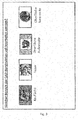
- a photo is stored in the exemplary embodiment for each cutter, which is displayed at choice of cutter or when displaying the selection.
- the software may additionally include the ability to select different operating modes. With the selection of the mode there are different possibilities of the parameter change. Thus, for example, in a "high-professional" mode, a milling cutter can be selected from various existing milling cutters, while in a “professional” mode, the milling cutter to be used is specified.
- the change after changing at least one parameter, the change must be confirmed separately again. This increases the security against incorrect parameterizations. Only then does the software jump to the next selection mask.
- This graphical user interface adds the software with an icon for opening the new graphical user interfaces. This is in FIG. 2 shown.
- FIG. 3 illustrated graphical user interface allows a selection of the range of CAD design whose editing is to be parameterized.
- Selecting the area to be machined will automatically duplicate the dedicated milling strategy in the background of the software to be able to change. This happens without the user being able to recognize this.
- the milling cutter stored for processing the corresponding area appears. This is in FIG. 4 shown.
- Information about the cutter is displayed, such as an NC number that indicates the position of the cutter in the CAM system. Further information can be type, length, tool reference, cutting length, diameter, tip length, shank diameter, simulation accuracy and fiber length. In "Professional" mode, the cutter is unchangeable.
- the milling cutter used in this milling strategy appears.
- the name of the milling cutter is displayed and a photo of the milling cutter. Only by confirming with OK will the next mask be opened, which will be displayed in FIG. 5 is shown.
- these parameters can be changed via graphical controls.
- these are sliders. Knobs are also possible. Discrete selection systems are also possible.
- the direct entry or change of numerical values can be made possible.
- the expert system is stored in the background in the background. This does not allow or warns if parameters are entered for the cutter that could damage it or even break it.
- the parameters stored in the expert system are material-dependent. By updating this database can be adapted again and again, so that new routers or new materials can be stored.
- graphical, for example, color change of the graphic controller the user is notified when an actual change in parameters causes the End mill is at risk. In this window, the selected cutter is shown as well as the selected processing area. As the parameters change, so does the appearance of the image of the editing area, for example, its surface becomes smoother.
- FIG. 6 again shows the in FIG. 3 illustrated graphical user interface. The process returns here and allows the selection of another area of the CAD design whose processing is to be parametrized.
- the display of the associated symbol changes (for example, changing the color of a frame or background area of the symbol). Now the user can also decide whether additional areas should be changed or whether the milling path strategy should be calculated with the existing parameters.
- the milling cutter to be used for machining the corresponding area can be selected by the user from a large number of different milling cutters available in the CAM system.
- all required tool data can be entered manually, as in FIG. 7 is shown by way of example.
- a cutter can be selected by entering its serial number.
- the position i. the position of the tool in the machine (NC number) can be entered.
- the selected tool is again graphically displayed in realistic terms. If several tools with the same geometry are stored in the milling library, they are all displayed graphically with article number and the user can select the existing one.
- a machining tool can be individually defined for each area of surface processing of the CAD design.
- the expert system may advantageously include data on as many as possible marketable and fundamentally suitable processing tools, the data being kept current via automatic updates. Then the device needs a corresponding interface for the update, such as an Internet connection.
Abstract
Es wird eine Vorrichtung für eine parametrisierbare Bearbeitungseinrichtung beschrieben, wobei die Bearbeitungseinrichtung zur Bearbeitung eines Rohlings mittels mindestens eines Bearbeitungswerkzeugs geeignet ist. Die erfindungsgemäß vorgestellte Vorrichtung umfasst eine graphische Benutzerschnittstelle zur Veränderung mindestens eines Parameterwertes der Bearbeitungseinrichtung. Die erfindungsgemäß vorgestellte Vorrichtung ist dadurch gekennzeichnet, dass die graphische Benutzerschnittstelle so ausgebildet ist, dass der Parameterwert durch Manipulation eines graphisch dargestellten Elements mittels einer Zeigevorrichtung verändert werden kann.A device for a parameterizable processing device is described, wherein the processing device is suitable for processing a blank by means of at least one processing tool. The device presented according to the invention comprises a graphical user interface for changing at least one parameter value of the processing device. The device presented according to the invention is characterized in that the graphical user interface is designed so that the parameter value can be changed by manipulating a graphically displayed element by means of a pointing device.
Description
Parametrisierbare Bearbeitungseinrichtungen wie beispielsweise computerunterstützte Fertigungsanlagen (CAM Systeme) werden in vielfältiger Weise eingesetzt. Ein Beispiel ist die Fertigung von Einzelstücken aus Rohlingen.Parameterisable processing devices such as computer-aided manufacturing (CAM) systems are used in a variety of ways. One example is the production of individual pieces from blanks.
Um möglichst flexibel mit unterschiedlichen Bearbeitungsanforderungen umgehen zu können, sind parametrisierbare Bearbeitungseinrichtungen beispielsweise als 5 Achs Fräsmaschinen ausgebildet.In order to be able to deal with different processing requirements as flexibly as possible, parametrizable processing devices are designed, for example, as 5-axis milling machines.
Für die Herstellung von Einzelstücken wie beispielsweise Zahnersatz (dentale CAM Programme) ist dieser Funktionsumfang allerdings meist nicht notwendig. Zudem erfordert die sich aus der Vielzahl von Achsen ergebende Komplexität Expertenwissen bei der Parametrisierung.For the production of individual pieces such as dental prostheses (dental CAM programs), however, this functionality is usually not necessary. In addition, the complexity resulting from the large number of axes requires expert knowledge in the parameterization.
Dentale CAM Programme, die bezüglich geringster Fräszeit und höchster Fräserstandzeit hin optimiert sind, können beispielsweise auf industriell geprägten CAM Systemen aufsetzen. Nachteil der Optimierung bezüglich Fräszeit und Fräserstandzeit ist, dass sie dem Zahntechniker so gut wie keine Möglichkeiten bietet, in die Qualität der Fräsung einzugreifen.Dental CAM programs that are optimized with regard to minimum milling time and maximum milling tool life can, for example, be based on industrial CAM systems. Disadvantage of the optimization in terms of milling time and cutter life is that it offers the dental technician as good as no opportunities to intervene in the quality of the milling.
Andererseits ist eine Parametrisierung, die auch die Qualität der hergestellten Einzelstücke optimiert, ohne Expertenwissen fast unmöglich, auch weil alle Parameteränderungen in Tabellen vorgenommen werden.On the other hand, parameterization, which also optimizes the quality of the individual pieces produced, is almost impossible without expert knowledge, also because all parameter changes are made in tables.
Die Erfindung befasst sich mit der Aufgabe, die Parametrisierung von Bearbeitungsmaschinen zu erleichtern.The invention is concerned with the task of facilitating the parameterization of processing machines.
Erfindungsgemäß wird daher eine Vorrichtung für eine parametrisierbare Bearbeitungseinrichtung vorgestellt, wobei die Bearbeitungseinrichtung zur Bearbeitung eines Rohlings mittels mindestens eines Bearbeitungswerkzeugs geeignet ist. Die erfindungsgemäß vorgestellte Vorrichtung umfasst eine graphische Benutzerschnittstelle zur Veränderung mindestens eines Parameterwertes der Bearbeitungseinrichtung. Die erfindungsgemäß vorgestellte Vorrichtung ist dadurch gekennzeichnet, dass die graphische Benutzerschnittstelle so ausgebildet ist, dass der Parameterwert durch Manipulation eines graphisch dargestellten Elements mittels einer Zeigevorrichtung verändert werden kann.According to the invention, therefore, a device for a parameterizable processing device is presented, wherein the processing device is suitable for processing a blank by means of at least one processing tool. The device presented according to the invention comprises a graphical user interface for changing at least one parameter value of the processing device. The device presented according to the invention is characterized in that the graphical user interface is designed so that the parameter value can be changed by manipulating a graphically displayed element by means of a pointing device.
In einer Ausführungsform kann die Vorrichtung weiterhin ein Expertensystem umfassen, das ausgebildet ist, zu weiteren Parameterwerten der Bearbeitungseinrichtung mindestens einen Grenzwert für den veränderbaren Parameterwert zu bestimmen, und wobei die graphische Benutzerschnittstelle weiterhin ausgebildet ist, durch Veränderung der graphischen Darstellung des graphischen Elements eine Über- oder Unterschreitung des Grenzwertes infolge der Veränderung des veränderbaren Parameterwertes sichtbar zu machen.In one embodiment, the apparatus may further comprise an expert system configured to determine at least one limit value for the variable parameter value for further parameter values of the processing device, and wherein the graphical user interface is further configured to change an override of the graphical representation of the graphical element. or below the limit value as a result of the change in the variable parameter value.
Dabei kann der Grenzwert so gewählt sein, dass er einen ersten Parameterwertbereich des veränderbaren Parameterwertes von einem zweiten Parameterwertbereich des veränderbaren Parameterwertes trennt, wobei bei Verwendung eines Parameterwertes aus dem ersten Parameterwertbereich eine Beschädigung des Bearbeitungswerkzeugs nicht zu erwarten ist und bei Verwendung eines Parameterwertes aus dem zweiten Parameterwertbereich eine Beschädigung des Bearbeitungswerkzeugs zu erwarten ist.In this case, the limit value may be selected such that it separates a first parameter value range of the variable parameter value from a second parameter value range of the variable parameter value, wherein damage to the machining tool is not to be expected when using a parameter value from the first parameter value range and when using a parameter value from the second Parameter value range is expected to damage the editing tool.
Die Bearbeitungseinrichtung kann insbesondere zur Bearbeitung von mindestens einer Oberfläche des Rohlings geeignet sein. Dann kann die graphische Benutzerschnittstelle weiterhin ausgebildet sein, eine Veränderung der Bearbeitung der mindestens einer Oberfläche infolge der Veränderung des veränderbaren Parameterwertes graphisch darzustellen.The processing device may in particular be suitable for processing at least one surface of the blank. Then, the graphical user interface may be further configured to graphically represent a change in the processing of the at least one surface due to the change in the variable parameter value.
Die Bearbeitungseinrichtung kann insbesondere zur Herstellung eines Zahnersatzes geeignet sein und die mindestens eine Oberfläche kann eine Kauoberfläche, eine Fissuroberfläche, eine Außenseitenoberfläche oder eine Innenseitenoberfläche des Zahnersatzes sein.The processing device may in particular be suitable for producing a dental prosthesis and the at least one surface may be a chewing surface, a fissure surface, an outer side surface or an inner side surface of the dental prosthesis.
Dann kann über die graphische Benutzerschnittstelle eingestellt werden, ob die Kauoberfläche, die Fissuroberfläche, die Außenseitenoberfläche oder eine Innenseitenoberfläche des Zahnersatzes bearbeitet werden soll, wobei die Bearbeitungseinrichtung zur Bearbeitung der unterschiedlichen Oberflächen unterschiedliche Bearbeitungswerkzeuge umfasst und wobei die graphische Benutzerschnittstelle weiterhin ausgebildet ist, eine Bezeichnung und/oder ein Bild des Bearbeitungswerkzeuges für die jeweilige Oberfläche darzustellen.Then, via the graphical user interface, whether the chewing surface, the fissure surface, the outside surface or an inside surface of the denture is to be processed, the processing means for processing the different surfaces comprises different processing tools and wherein the graphical user interface is further formed, a name and / or to display an image of the processing tool for the respective surface.
Die graphische Benutzerschnittstelle kann auch eine Auswahl des Bearbeitungswerkzeugs ermöglichen.The graphical user interface may also enable selection of the editing tool.
Dabei kann die Auswahl des Bearbeitungswerkzeugs zumindest durch Eingabe einer NC-Nummer erfolgen, wobei die NC-Nummer eine Position des ausgewählten Bearbeitungswerkzeugs in der Bearbeitungsvorrichtung angibt.In this case, the selection of the machining tool can be done at least by entering an NC number, wherein the NC number indicates a position of the selected machining tool in the processing device.
Dabei kann die graphische Benutzerschnittstelle ausgebildet sein, die unterschiedlichen Bearbeitungswerkzeuge der Bearbeitungsvorrichtung graphisch anzuzeigen und eine mittels der Zeigevorrichtung vorgenommene Auswahl eines der unterschiedlichen Bearbeitungswerkzeuge entgegenzunehmen.In this case, the graphical user interface can be designed to graphically display the different processing tools of the processing device and to accept a selection made by the pointing device of one of the different processing tools.
Die Bearbeitungseinrichtung kann beispielsweise eine Fräse zum Abtragen von Material von dem Rohling umfassen und der veränderbare Parameterwert kann eine Drehzahl der Fräse, ein Vorschub der Fräse, einen Fräsbahnabstand oder eine Menge abzutragenden Materials sein.The processing device may, for example, comprise a milling cutter for removing material from the blank, and the variable parameter value may be a rotational speed of the milling cutter, a feed of the milling cutter, a milling track distance or a quantity of material to be removed.
Vorteilhafte Weiterbildungen der Erfindung sind in den Unteransprüchen angegeben und in der Beschreibung beschrieben.Advantageous developments of the invention are specified in the subclaims and described in the description.
Ausführungsbeispiele der Erfindung werden anhand der Zeichnungen und der nachfolgenden Beschreibung näher erläutert. Es zeigen:
-
Figur 1 -
Figur 2 -
Figur 3 eine zweite beispielhafte Darstellung auf einer graphischen Benutzeroberfläche, wie sie im Rahmen der vorliegenden Erfindung Verwendung finden kann, -
Figur 4 eine dritte beispielhafte Darstellung auf einer graphischen Benutzeroberfläche, wie sie im Rahmen der vorliegenden Erfindung Verwendung finden kann, -
Figur 5 eine vierte beispielhafte Darstellung auf einer graphischen Benutzeroberfläche, wie sie im Rahmen der vorliegenden Erfindung Verwendung finden kann, -
Figur 6 -
Figur 7 eine sechste beispielhafte Darstellung auf einer graphischen Benutzeroberfläche, wie sie im Rahmen der vorliegenden Erfindung Verwendung finden kann, und -
Figur 8 eine siebte beispielhafte Darstellung auf einer graphischen Benutzeroberfläche, wie sie im Rahmen der vorliegenden Erfindung Verwendung finden kann.
-
FIG. 1 a representation on a graphical user interface according to the prior art, -
FIG. 2 a first exemplary representation on a graphical user interface, as it can be used in the context of the present invention, -
FIG. 3 a second exemplary representation on a graphical user interface, as it can be used in the context of the present invention, -
FIG. 4 a third exemplary representation on a graphical user interface, as it can be used in the context of the present invention, -
FIG. 5 a fourth exemplary representation on a graphical user interface, as it can be used in the context of the present invention, -
FIG. 6 a fifth exemplary representation on a graphical user interface, as it can be used in the context of the present invention, -
FIG. 7 a sixth exemplary representation on a graphical user interface, as it can be used in the context of the present invention, and -
FIG. 8 a seventh exemplary representation on a graphical user interface, as it can be used in the context of the present invention.
Mit dem hier vorgestellten Ansatz soll es dem "normalen" Zahntechniker möglich sein, die CAM-Software mit einfachen Mitteln besser zu beherrschen und so ein besseres Ergebnis herstellen zu können. Dies wird mit der graphischen Darstellung von einzeln zu verändernden Parametern ermöglicht. Die hier beispielhaft vorgestellte Vorrichtung ist eine durch Steueranweisungen (Software) ertüchtigte Steuervorrichtung (Computer) mit graphischer Schnittstelle (Bildschirm) und Zeigevorrichtung (Maus), wobei die Software auf ein CAM-System aufsetzt und unter anderem eine grafische Bedienoberfläche, die auch als graphische Benutzerschnittstelle bezeichnet wird, für das CAM-System bereitstellt. Beispielsweise kann die Software in einem Speicher des CAM-Systems hinterlegt und von einer Rechnereinheit des CAM-Systems ausgeführt werden. Alternativ kann die Steuervorrichtung über eine Schnittstelle mit der Rechnereinheit des CAM-Systems kommunizieren.With the approach presented here, it should be possible for the "normal" dental technician to master the CAM software more easily with simple means and thus be able to produce a better result. This is made possible with the graphic representation of parameters to be changed individually. The device exemplified here is one by control instructions (Software) enhanced control device (computer) with graphical interface (screen) and pointing device (mouse), wherein the software is based on a CAM system and provides, inter alia, a graphical user interface, also referred to as graphical user interface for the CAM system , For example, the software can be stored in a memory of the CAM system and executed by a computer unit of the CAM system. Alternatively, the control device can communicate via an interface with the computer unit of the CAM system.
Die grafische Bedienoberfläche des Ausführungsbeispiels kann besonders vorteilhaft im dentalen Bereich aber nicht nur dort genutzt werden. Sie erleichtert die Parametrisierung von CAM-Systemen für jedwede gewerbliche Anwendung beispielsweise auch im industriellen Bereich.The graphical user interface of the embodiment can be particularly advantageous in the dental field but not only used there. It facilitates the parameterization of CAM systems for any commercial application, for example in the industrial sector.
Zusätzlich zur grafischen Bedienoberfläche kann auch ein "Expertensystem" innerhalb der Software hinterlegt sein. Der in den Figuren beispielhaft dargestellte Arbeitsfluss bzw. die graphische Benutzeroberfläche und -führung kann in jede CAM-Software integriert werden bzw. auf entsprechende Schnittstellen von CAM-Systemen aufsetzen.In addition to the graphical user interface, an "expert system" can also be stored within the software. The workflow shown in the figures by way of example or the graphic user interface and guidance can be integrated into any CAM software or set up on corresponding interfaces of CAM systems.
In einem Ausführungsbeispiel ist in die Software eine Fräserbibliothek hinterlegt, die im Ausführungsbeispiel zusätzlich optional per Update aktualisiert werden kann. Über die Eingabe der Herstellerartikelnummer wird dann der Fräser ausgewählt. Umgekehrt kann im Ausführungsbeispiel über die Eingabe von Fräserparametern, wie z.B. Durchmesser und Schaftlänge ein oder mehrere Fräser aus der Bibliothek herausgesucht werden, um diesen zu bestellen. Zusätzlich ist im Ausführungsbeispiel zu jedem Fräser ein Foto hinterlegt, das bei Fräserauswahl bzw. beim Anzeigen der Auswahl mit angezeigt wird.In one embodiment, a cutter library is stored in the software, which can also be optionally updated in the exemplary embodiment by updating. The milling cutter is then selected by entering the manufacturer's article number. Conversely, in the embodiment, the input of milling parameters, such as e.g. Diameter and shaft length one or more cutters are picked out of the library to order this. In addition, a photo is stored in the exemplary embodiment for each cutter, which is displayed at choice of cutter or when displaying the selection.
Die Software kann zusätzlich die Möglichkeit zur Auswahl unterschiedliche Betriebsmodi umfassen. Mit der Auswahl des Modus ergeben sich unterschiedliche Möglichkeiten der Parameteränderung. So kann beispielsweise in einem "High Professional" Modus ein Fräser aus unterschiedlichen vorhandenen Fräsern ausgewählt werden, während in einem Modus "Professional" der zu verwendende Fräser vorgegeben sind.The software may additionally include the ability to select different operating modes. With the selection of the mode there are different possibilities of the parameter change. Thus, for example, in a "high-professional" mode, a milling cutter can be selected from various existing milling cutters, while in a "professional" mode, the milling cutter to be used is specified.
Eine Änderung der Parameter erfolgt entweder graphisch oder durch eine direkte Eingabe eines Wertes. Als graphisches Element dient z.B. ein Schieberegler. Wird ein Parameter verändert, wird in einem separaten Bildschirmbereich die Veränderung der bearbeiteten Fläche angezeigt (z.B. eine glättere Oberfläche). Regelungselemente sind zum Beispiel für die folgenden Parameter bei der Bearbeitung von CAD-Konstruktionen vorgesehen:
- Drehzahl
- Vorschub
- Zustellung (Fräsbahnabstand)
- Aufmass (Material Auftrag bzw. Abtrag)
- rotation speed
- feed
- Infeed (milling path distance)
- Measure (material order or removal)
Im Ausführungsbeispiel muss nach Änderung mindestens eines Parameters die Änderung noch einmal separat bestätigt werden. Dies erhöht die Sicherheit vor Fehlparametrisierungen. Erst dann springt die Software in die nächste Auswahlmaske.In the exemplary embodiment, after changing at least one parameter, the change must be confirmed separately again. This increases the security against incorrect parameterizations. Only then does the software jump to the next selection mask.
Ein Ablauf des Modus "Professional" am Beispiel Bearbeitung eines Rohlings zur Herstellung eines individuellen Zahnersatzes ist in den Figuren beispielhaft dargestellt.A sequence of the mode "Professional" on the example of processing a blank for the production of an individual tooth replacement is shown by way of example in the figures.
Im Folgenden wird ein Verfahren beschrieben, wie es unter Verwendung der erfindungsgemäßen Vorrichtung durchgeführt werden kann:
- Zuerst wird ein zu fräsendes Werkstück in einem Materialblock einer parametrisierbaren Bearbeitungsvorrichtung platziert. Ein Beispiel für eine solche Bearbeitungsvorrichtung ist Hyperdent von der Firma Follow me. Die graphische Benutzerschnittstelle nach Stand der Technik ist in
Figur 1
- First, a workpiece to be milled is placed in a block of material of a parameterisable processing device. An example of such a processing device is Hyperdent from Follow Me. The graphical user interface of the prior art is in
FIG. 1 shown.
Dieser graphischen Benutzerschnittstelle fügt die Software ein Icon zum Öffnen der neuen graphischen Benutzerschnittstellen hinzu. Dies ist in
Wenn sich der Mauszeiger über dem Icon befindet, erscheint ein Fenster, in dem darüber informiert wird, dass das Anklicken des Icons die neuen graphischen Benutzerschnittstellen öffnet. Durch Anklicken des Icons springt die Software zur in
Die in
Mit dem Auswählen des zu bearbeitenden Bereiches wird automatisch die dafür vorgesehene Frässtrategie im Hintergrund der Software dupliziert, um diese verändern zu können. Dies geschieht, ohne dass der Anwender dies erkennen kann.Selecting the area to be machined will automatically duplicate the dedicated milling strategy in the background of the software to be able to change. This happens without the user being able to recognize this.
Es erscheint der für die Bearbeitung des entsprechenden Bereichs hinterlegte Fräser. Dies ist in
Es erscheint der in dieser Frässtrategie verwendete Fräser. Die Bezeichnung des Fräsers wird angezeigt und ein Foto des Fräsers. Erst durch Bestätigen mit OK wird die nächste Maske geöffnet, die in
Die in
Im in
- Drehzahl
- Vorschub
- Zustellung (Fräsbahnabstand)
- Aufmass (Material Auf-, Abtrag)
- rotation speed
- feed
- Infeed (milling path distance)
- Measure (material build-up, removal)
Diese Parameter lassen sich über graphische Bedienelemente verändern. Im Beispiel sind dies Schieberegler. Drehregler sind ebenfalls möglich. Auch diskrete Auswahlsysteme sind möglich. Zusätzlich kann auch die direkte Eingabe oder Änderung numerischer Werte ermöglicht werden. In diesem Bereich ist im Beispiel im Hintergrund das Expertensystem hinterlegt. Dieses lässt nicht zu bzw. warnt davor, wenn für den Fräser Parameter eingegeben werden, die diesen beschädigen oder gar brechen lassen könnten. Die in dem Expertensystem (Datenbank) hinterlegten Parameter sind materialabhängig. Per Update kann diese Datenbank immer wieder angepasst werden, so dass neue Fräser bzw. neue Materialien hinterlegt werden können. Durch graphische, beispielsweise farbliche Änderung des graphischen Reglers wird der Benutzer darauf hingewiesen, wenn eine aktuelle Parameteränderung dazu führt, dass der Fräser gefährdet ist. In diesem Fenster wird der ausgewählte Fräser bildlich dargestellt als auch der ausgewählte Bearbeitungsbereich. Mit Veränderung der Parameter verändert sich auch die Darstellung des Bildes des Bearbeitungsbereiches, z.B. wird seine Oberfläche glatter.These parameters can be changed via graphical controls. In the example these are sliders. Knobs are also possible. Discrete selection systems are also possible. In addition, the direct entry or change of numerical values can be made possible. In this example, the expert system is stored in the background in the background. This does not allow or warns if parameters are entered for the cutter that could damage it or even break it. The parameters stored in the expert system (database) are material-dependent. By updating this database can be adapted again and again, so that new routers or new materials can be stored. By graphical, for example, color change of the graphic controller, the user is notified when an actual change in parameters causes the End mill is at risk. In this window, the selected cutter is shown as well as the selected processing area. As the parameters change, so does the appearance of the image of the editing area, for example, its surface becomes smoother.
Sind alle Parameter eingestellt muss die Eingabe wieder bestätigt werden.If all parameters have been set, the entry must be confirmed again.
Wurden die Bearbeitung eines oder mehrerer Bereiche der CAD-Konstruktion parametrisiert, so verändert sich die Darstellung des zugehörigen Symbols (zum Beispiel farbliche Änderung eines Rahmens oder Hintergrundbereichs des Symbols). Jetzt kann der Anwender auch entscheiden, ob weitere Bereiche geändert werden sollen, oder ob die Fräsbahnstrategie mit den vorhandenen Parametern berechnet werden soll.If the editing of one or more areas of the CAD design has been parameterized, the display of the associated symbol changes (for example, changing the color of a frame or background area of the symbol). Now the user can also decide whether additional areas should be changed or whether the milling path strategy should be calculated with the existing parameters.
Im "High Professional" Modus kann der für die Bearbeitung des entsprechenden Bereichs zu verwendende Fräser vom Anwender aus einer Menge unterschiedlicher und im CAM System verfügbaren Fräsern ausgewählt werden.In the "High Professional" mode, the milling cutter to be used for machining the corresponding area can be selected by the user from a large number of different milling cutters available in the CAM system.
Er kann diesen Wechsel auf zwei Arten durchführen. Zum einen können alle benötigten Werkzeugdaten manuell eingetragen werden, wie dies in
Sofern im Expertensystem nicht nur die im CAM System verfügbaren Fräser hinterlegt sind, muss bei beiden Eingabearten auch die Position, d.h. der Standplatz des Werkzeuges in der Maschine (NC-Nummer) eingegeben werden.If not only the milling cutters available in the CAM system are stored in the expert system, the position, i. the position of the tool in the machine (NC number) can be entered.
Das ausgewählte Werkzeug wird wieder realistisch graphisch dargestellt. Sind in der Fräserbibliothek mehrere Werkzeuge mit der gleichen Geometrie hinterlegt, werden diese alle graphisch mit Artikelnummer angezeigt und der Benutzer kann das vorhandene auswählen.The selected tool is again graphically displayed in realistic terms. If several tools with the same geometry are stored in the milling library, they are all displayed graphically with article number and the user can select the existing one.
Wird die Artikelnummer eines Werkzeuges eingetragen, werden aus der Bibliothek heraus alle Werkzeugparameter automatisch übernommen. Nur die Position (NC-Nummer) ist dann in diesem Falle einzutragen.If the article number of a tool is entered, all tool parameters are automatically taken from the library. Only the position (NC number) is then entered in this case.
Ist das Werkzeug ausgewählt, muss die Auswahl wieder bestätigt werden.If the tool is selected, the selection must be confirmed again.
Für jeden Bereich der Oberflächenbearbeitung der CAD-Konstruktion kann dabei ein Bearbeitungswerkzeug individuell definiert werden.A machining tool can be individually defined for each area of surface processing of the CAD design.
Das Expertensystem kann aber vorteilhafter Weise Daten zu möglichst allen marktverfügbaren und grundsätzlich geeigneten Bearbeitungswerkzeugen umfassen, wobei die Daten über automatische Updates aktuell gehalten werden. Dann benötigt die Vorrichtung eine entsprechende Schnittstelle für das Update, etwa eine Internetverbindung.However, the expert system may advantageously include data on as many as possible marketable and fundamentally suitable processing tools, the data being kept current via automatic updates. Then the device needs a corresponding interface for the update, such as an Internet connection.
Claims (10)
Applications Claiming Priority (1)
| Application Number | Priority Date | Filing Date | Title |
|---|---|---|---|
| DE102013211860.0A DE102013211860A1 (en) | 2013-06-21 | 2013-06-21 | Device for a parameterizable processing device |
Publications (2)
| Publication Number | Publication Date |
|---|---|
| EP2818950A2 true EP2818950A2 (en) | 2014-12-31 |
| EP2818950A3 EP2818950A3 (en) | 2016-02-24 |
Family
ID=50943134
Family Applications (1)
| Application Number | Title | Priority Date | Filing Date |
|---|---|---|---|
| EP14172175.3A Withdrawn EP2818950A3 (en) | 2013-06-21 | 2014-06-12 | Apparatus for changing a parameter of a machining device using a graphical user interface |
Country Status (2)
| Country | Link |
|---|---|
| EP (1) | EP2818950A3 (en) |
| DE (1) | DE102013211860A1 (en) |
Families Citing this family (1)
| Publication number | Priority date | Publication date | Assignee | Title |
|---|---|---|---|---|
| JP6371335B2 (en) | 2016-05-30 | 2018-08-08 | Dmg森精機株式会社 | Processing status display device |
-
2013
- 2013-06-21 DE DE102013211860.0A patent/DE102013211860A1/en not_active Withdrawn
-
2014
- 2014-06-12 EP EP14172175.3A patent/EP2818950A3/en not_active Withdrawn
Non-Patent Citations (1)
| Title |
|---|
| None |
Also Published As
| Publication number | Publication date |
|---|---|
| EP2818950A3 (en) | 2016-02-24 |
| DE102013211860A1 (en) | 2014-12-24 |
Similar Documents
| Publication | Publication Date | Title |
|---|---|---|
| DE102010036499B4 (en) | Tool vector display device for a machine tool with a rotation axis | |
| EP1480095B1 (en) | Method and system for generating or visualising control data sets | |
| EP2138914B1 (en) | Method and device for optimising, monitoring or analysing a process | |
| DE102005047466B3 (en) | Method for optimizing the machining process in a machine | |
| DE102013011688B4 (en) | Data display device for machine tools for displaying data due to predetermined conditions | |
| DE102013010853B4 (en) | Numerical control device having a program restart function | |
| DE102017116459B4 (en) | CAD/CAM CNC INTEGRATED SYSTEM | |
| DE102013101838A1 (en) | Curve progression display device with data management function | |
| DE2940444C2 (en) | Copy control device for a copy milling machine with tool changing device | |
| DE112018008126T5 (en) | Machine learning device, machining program generation device and machine learning method | |
| DE112018007741B4 (en) | MACHINE LEARNING DEVICE AND DEVICE FOR GENERATING PROGRAMS FOR NUMERICALLY CONTROLLED MACHINING | |
| DE19614202C2 (en) | Method and device for controlling a machine tool, in particular a spark erosion machine | |
| DE102016003898A1 (en) | Numerical control with program display function using a variety of images | |
| EP1300740A1 (en) | Process and apparatus to establish or amend nc-programs | |
| EP3295265B1 (en) | Operating module for a machine in the food industry | |
| DE102006001496A1 (en) | Work piece geometrical changes determining system, has evaluation unit for evaluating differential geometrical value, which specifies difference between work piece geometrical value and reference geometrical value | |
| EP2818950A2 (en) | Apparatus for changing a parameter of a machining device using a graphical user interface | |
| EP3868330A1 (en) | Method for producing a dental restoration | |
| DE102020116210A1 (en) | Parameter management device and parameter management system | |
| DE102014016807B4 (en) | Numerical control device with a function for simultaneously executing a plurality of instructions using data in table format | |
| DE10245890B4 (en) | Screen element, HMI device, automation system and computer program product for visualizing and configuring single and multiple user texts and the places of use assigned in a data processing system | |
| CH702705B1 (en) | Blade manufacturing method for e.g. turbine to control five-axle machine tool for machining workpiece, involves supplying numeric control-program code to machine tool for manufacturing blade under application of milling process using tool | |
| EP2299341A1 (en) | Editing device and method for configuring parameters of an industrial automation arrangement | |
| EP4073603A1 (en) | Optimisation of chip removal processes on machine tools | |
| EP4137898B1 (en) | Control device for a cnc control system |
Legal Events
| Date | Code | Title | Description |
|---|---|---|---|
| PUAI | Public reference made under article 153(3) epc to a published international application that has entered the european phase |
Free format text: ORIGINAL CODE: 0009012 |
|
| 17P | Request for examination filed |
Effective date: 20140612 |
|
| AK | Designated contracting states |
Kind code of ref document: A2 Designated state(s): AL AT BE BG CH CY CZ DE DK EE ES FI FR GB GR HR HU IE IS IT LI LT LU LV MC MK MT NL NO PL PT RO RS SE SI SK SM TR |
|
| AX | Request for extension of the european patent |
Extension state: BA ME |
|
| PUAL | Search report despatched |
Free format text: ORIGINAL CODE: 0009013 |
|
| AK | Designated contracting states |
Kind code of ref document: A3 Designated state(s): AL AT BE BG CH CY CZ DE DK EE ES FI FR GB GR HR HU IE IS IT LI LT LU LV MC MK MT NL NO PL PT RO RS SE SI SK SM TR |
|
| AX | Request for extension of the european patent |
Extension state: BA ME |
|
| RIC1 | Information provided on ipc code assigned before grant |
Ipc: G05B 19/4093 20060101ALI20160120BHEP Ipc: G05B 19/409 20060101AFI20160120BHEP Ipc: G05B 19/042 20060101ALI20160120BHEP |
|
| R17P | Request for examination filed (corrected) |
Effective date: 20160824 |
|
| RBV | Designated contracting states (corrected) |
Designated state(s): AL AT BE BG CH CY CZ DE DK EE ES FI FR GB GR HR HU IE IS IT LI LT LU LV MC MK MT NL NO PL PT RO RS SE SI SK SM TR |
|
| STAA | Information on the status of an ep patent application or granted ep patent |
Free format text: STATUS: THE APPLICATION IS DEEMED TO BE WITHDRAWN |
|
| 18D | Application deemed to be withdrawn |
Effective date: 20190103 |