EP2818934A2 - Medium discharge device and image forming apparatus - Google Patents
Medium discharge device and image forming apparatus Download PDFInfo
- Publication number
- EP2818934A2 EP2818934A2 EP14172971.5A EP14172971A EP2818934A2 EP 2818934 A2 EP2818934 A2 EP 2818934A2 EP 14172971 A EP14172971 A EP 14172971A EP 2818934 A2 EP2818934 A2 EP 2818934A2
- Authority
- EP
- European Patent Office
- Prior art keywords
- discharge
- projection
- guide
- nips
- medium
- Prior art date
- Legal status (The legal status is an assumption and is not a legal conclusion. Google has not performed a legal analysis and makes no representation as to the accuracy of the status listed.)
- Granted
Links
- 238000007599 discharging Methods 0.000 claims description 27
- 238000011144 upstream manufacturing Methods 0.000 claims description 10
- 230000037303 wrinkles Effects 0.000 description 6
- 230000000052 comparative effect Effects 0.000 description 5
- 238000005452 bending Methods 0.000 description 3
- 238000012986 modification Methods 0.000 description 2
- 230000004048 modification Effects 0.000 description 2
- 230000008602 contraction Effects 0.000 description 1
- 230000007423 decrease Effects 0.000 description 1
- 229910052736 halogen Inorganic materials 0.000 description 1
- 150000002367 halogens Chemical class 0.000 description 1
- 230000002093 peripheral effect Effects 0.000 description 1
- 238000007665 sagging Methods 0.000 description 1
- 238000000926 separation method Methods 0.000 description 1
Images




Classifications
-
- B—PERFORMING OPERATIONS; TRANSPORTING
- B65—CONVEYING; PACKING; STORING; HANDLING THIN OR FILAMENTARY MATERIAL
- B65H—HANDLING THIN OR FILAMENTARY MATERIAL, e.g. SHEETS, WEBS, CABLES
- B65H29/00—Delivering or advancing articles from machines; Advancing articles to or into piles
- B65H29/12—Delivering or advancing articles from machines; Advancing articles to or into piles by means of the nip between two, or between two sets of, moving tapes or bands or rollers
- B65H29/125—Delivering or advancing articles from machines; Advancing articles to or into piles by means of the nip between two, or between two sets of, moving tapes or bands or rollers between two sets of rollers
-
- B—PERFORMING OPERATIONS; TRANSPORTING
- B65—CONVEYING; PACKING; STORING; HANDLING THIN OR FILAMENTARY MATERIAL
- B65H—HANDLING THIN OR FILAMENTARY MATERIAL, e.g. SHEETS, WEBS, CABLES
- B65H29/00—Delivering or advancing articles from machines; Advancing articles to or into piles
- B65H29/12—Delivering or advancing articles from machines; Advancing articles to or into piles by means of the nip between two, or between two sets of, moving tapes or bands or rollers
- B65H29/14—Delivering or advancing articles from machines; Advancing articles to or into piles by means of the nip between two, or between two sets of, moving tapes or bands or rollers and introducing into a pile
-
- B—PERFORMING OPERATIONS; TRANSPORTING
- B65—CONVEYING; PACKING; STORING; HANDLING THIN OR FILAMENTARY MATERIAL
- B65H—HANDLING THIN OR FILAMENTARY MATERIAL, e.g. SHEETS, WEBS, CABLES
- B65H29/00—Delivering or advancing articles from machines; Advancing articles to or into piles
- B65H29/52—Stationary guides or smoothers
-
- B—PERFORMING OPERATIONS; TRANSPORTING
- B65—CONVEYING; PACKING; STORING; HANDLING THIN OR FILAMENTARY MATERIAL
- B65H—HANDLING THIN OR FILAMENTARY MATERIAL, e.g. SHEETS, WEBS, CABLES
- B65H29/00—Delivering or advancing articles from machines; Advancing articles to or into piles
- B65H29/70—Article bending or stiffening arrangements
-
- G—PHYSICS
- G03—PHOTOGRAPHY; CINEMATOGRAPHY; ANALOGOUS TECHNIQUES USING WAVES OTHER THAN OPTICAL WAVES; ELECTROGRAPHY; HOLOGRAPHY
- G03G—ELECTROGRAPHY; ELECTROPHOTOGRAPHY; MAGNETOGRAPHY
- G03G15/00—Apparatus for electrographic processes using a charge pattern
- G03G15/65—Apparatus which relate to the handling of copy material
- G03G15/6552—Means for discharging uncollated sheet copy material, e.g. discharging rollers, exit trays
-
- B—PERFORMING OPERATIONS; TRANSPORTING
- B65—CONVEYING; PACKING; STORING; HANDLING THIN OR FILAMENTARY MATERIAL
- B65H—HANDLING THIN OR FILAMENTARY MATERIAL, e.g. SHEETS, WEBS, CABLES
- B65H2301/00—Handling processes for sheets or webs
- B65H2301/50—Auxiliary process performed during handling process
- B65H2301/51—Modifying a characteristic of handled material
- B65H2301/512—Changing form of handled material
- B65H2301/5122—Corrugating; Stiffening
-
- B—PERFORMING OPERATIONS; TRANSPORTING
- B65—CONVEYING; PACKING; STORING; HANDLING THIN OR FILAMENTARY MATERIAL
- B65H—HANDLING THIN OR FILAMENTARY MATERIAL, e.g. SHEETS, WEBS, CABLES
- B65H2404/00—Parts for transporting or guiding the handled material
- B65H2404/60—Other elements in face contact with handled material
- B65H2404/61—Longitudinally-extending strips, tubes, plates, or wires
-
- B—PERFORMING OPERATIONS; TRANSPORTING
- B65—CONVEYING; PACKING; STORING; HANDLING THIN OR FILAMENTARY MATERIAL
- B65H—HANDLING THIN OR FILAMENTARY MATERIAL, e.g. SHEETS, WEBS, CABLES
- B65H2801/00—Application field
- B65H2801/03—Image reproduction devices
- B65H2801/06—Office-type machines, e.g. photocopiers
Definitions
- the present invention relates to a medium discharge device for discharging a medium, such as a recording medium after printing, outside an apparatus, and an image forming apparatus including the medium discharge device.
- a general image forming apparatus such as a copier, a facsimile machine, and a scanner, includes a conveying path on which recording media are conveyed, discharge rollers for discharging the recording media outside the image forming apparatus, and a stacker on which the discharged recording media are stacked (for example, see Japanese Patent Application Publication No. 2012-93648 ).
- An aspect of the present invention is intended to reduce the occurrence of improper discharge of a medium.
- a medium discharge device including: a discharge tray having a placing surface on which a medium is to be placed; a first pair of discharge rollers configured to form a first nip between the first pair of discharge rollers, and rotate about respective axes parallel to each other to discharge the medium through the first nip in a discharging direction onto the discharge tray; a second pair of discharge rollers configured to form a second nip between the second pair of discharge rollers, and rotate about the respective axes to discharge the medium through the second nip in the discharging direction onto the discharge tray; and a discharge guide for guiding the medium discharged by the first pair of discharge rollers and the second pair of discharge rollers.
- the discharge guide includes: a first projection disposed between the first pair of discharge rollers and the second pair of discharge rollers in an axial direction parallel to the axes, the first projection projecting to the placing surface side relative to the first and second nips and having a first guide surface opposite to the placing surface; and a second projection disposed on an opposite side of the first projection with respect to the first pair of discharge rollers in the axial direction, the second projection projecting to the placing surface side relative to the first and second nips and having a second guide surface opposite to the placing surface.
- an image forming apparatus including the above described medium discharge device.
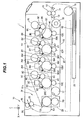
- FIG. 1 is a schematic view showing a configuration of an image forming apparatus 1 including a medium discharge device in the first embodiment.
- the image forming apparatus 1 includes four image forming units 2K, 2Y, 2M, and 2C, a transfer unit 27, a sheet cassette 25, a sheet feeding roller 11, an entrance sensor 12, a writing sensor 13, conveying rollers 14 and 15, a fixing unit 28, and a medium discharge device 70.
- the image forming units 2K, 2Y, 2M, and 2C form toner images of black (K), yellow (Y), magenta (M), and cyan (C), respectively.
- the image forming units 2K, 2Y, 2M, and 2C include LED heads 3K, 3Y, 3M, and 3C, photosensitive drums 4K, 4Y, 4M, and 4C, charging rollers 5K, 5Y, 5M, and 5C, developing rollers 6K, 6Y, 6M, and 6C, toner tanks,7K, 7Y, 7M, and 7C, developing blades 8K, 8Y, 8M, and 8C, and toner supplying sponge rollers 9K, 9Y, 9M, and 9C, respectively.
- the sheet cassette 25 stores recording sheets (e.g., sheets of paper) 40 as media.
- the sheet feeding roller 11 picks up and feeds the recording sheets 40 one by one from the sheet cassette 25 into a conveying path by cooperating with a separation member (not shown).
- the conveying rollers 14 and 15 conveys the fed recording sheet 40 to the transfer unit 27.
- the transfer unit 27 includes an endless conveying belt 18, a belt driven roller 16, a belt driving roller 17, and transfer rollers 10K, 10Y, 10M, and 10C.
- the conveying belt 18 conveys the recording sheet 40 from the conveying rollers 14 and 15.
- the transfer rollers 10K, 10Y, 10M, and 10C transfer the toner images from the image forming unit 2K, 2Y, 2M, and 2C to the recording sheet 40 conveyed on the conveying belt 18, respectively.
- the fixing unit 28 applies heat and pressure to the recording sheet 40 with the toner images transferred thereon to fix the toner images to the recording sheet 40.
- the fixing unit 28 includes a fixing roller 19 having a heater such as a halogen lamp therein and a fixing backup roller 20.
- the medium discharge device 70 includes a first discharge roller 22, a second discharge roller 23, a discharge guide 24, and a discharge tray 31.
- the first and second discharge rollers 22 and 23 discharge the recording sheet 40 after the fixing.
- the discharge guide 24 guides the recording sheet 40 discharged by the first and second discharge rollers 22 and 23.
- the discharge tray 31 stacks the recording sheet 40 discharged by the first and second discharge rollers 22 and 23.
- the discharge tray 31 has a placing surface 31a on which the recording sheet 40 is placed.
- the recording sheet 40 is conveyed on the conveying path in a conveying direction.
- the image forming apparatus 1 further includes motors for rotating the rollers and other rotating members, rollers disposed on the conveying path at intervals not longer than a length of a minimum recording sheet in the conveying direction, a solenoid for switching the conveying path, or the like, which are not shown in FIG. 1 .
- the motors includes a sheet feeding motor for mainly rotating the sheet feeding roller 11, a conveying motor for rotating the conveying rollers 14 and 15, a conveying belt motor for rotating the belt driving roller 17, a fixing motor for rotating the fixing roller 19, the fixing backup roller 20, and the discharge rollers 22 and 23, image forming motors for individually rotationally driving the image forming units 2K, 2Y, 2M, and 2C, and the like.
- the X-axis represents a direction in which the recording sheet 40 is conveyed when passing through the image forming units 2K, 2Y, 2M, and 2C
- the Y-axis represents a direction parallel to axes of rotation of the photosensitive drums 4K, 4Y, 4M, and 4C
- the Z-axis represents a direction perpendicular to both the X-axis and the Y-axis.
- the image forming apparatus 1 is set so that the Z-axis is directed in a substantially vertical direction.
- FIG. 2 is an enlarged partial sectional view showing the medium discharge device 70 in FIG. 1 .
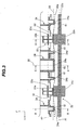
- FIG. 3 is a main part sectional view along line A-A in FIG. 2 .
- FIG. 4 is a sectional view along line B-B in FIG. 3 .
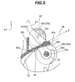
- FIG. 5 is a sectional view along line C-C in FIG. 3 .
- FIG. 6 is a sectional view along line D-D in FIG. 3 .
- the first discharge roller 22, the second discharge roller 23, the discharge guide 24, and the discharge tray 31 are attached to a main body 80 of the image forming apparatus 1.
- the main body 80 has a guide portion 81 for guiding the recording sheet 40 from the fixing unit 28.
- the first discharge roller 22 has an axis of rotation A1 (referred to below simply as the axis A1) parallel to the Y-axis.
- the second discharge roller 23 has an axis of rotation A2 (referred to below simply as the axis A2) parallel to the Y-axis.
- the first discharge roller 22 and the second discharge roller 23 are disposed to form nips between their peripheral surfaces.
- the first discharge roller 22 and the second discharge roller 23 discharge the recording sheet 40 in a discharging direction (indicated by arrow G in FIG. 2 ), which is perpendicular to a virtual line 57 (indicated by the dashed-dotted line in FIG. 2 ) perpendicularly intersecting the axes A1 and A2.
- the discharging direction i.e., the direction of arrow G
- the first discharge roller 22 is disposed below the second discharge roller 23 and on a discharge side (or the discharge tray 31 side) of the second discharge roller 23 in a horizontal direction.
- the second discharge roller 23 includes a pair of roller portions 23a and 23b having the same shape.
- the roller portions 23a and 23b are disposed rotatably about the axis A2 at a predetermined interval.
- the roller portions 23a and 23b respectively have shafts 23c and 23d on the same axis A2.
- the first discharge roller 22 has a shaft 22c parallel to the shafts 23c and 23d of the second discharge roller 23, and a pair of roller portions 22a and 22b formed on the shaft 22c so as to face the pair of roller portions 23a and 23b of the second discharge roller 23.
- the roller portions 22a and 22b have the same shape, and are slightly wider than the roller portions 23a and 23b in the Y-axis direction, respectively.
- the roller portions 22a and 23a form a nip 51 at a roller facing portion at which the roller portions 22a and 23a face each other.
- the roller portions 22b and 23b form a nip 52 at a roller facing portion at which the roller portions 22b and 23b face each other.
- the first discharge roller 22 receives rotational force to rotate in a direction for discharging the recording sheet 40, and the pair of roller portions 23a and 23b of the second discharge roller 23 are rotated by the rotation of the first discharge roller 22 by friction with the first discharge roller 22 either directly or via the recording sheet 40. That is, the first discharge roller 22 is a driving roller and the second discharge roller 23 is a driven roller.
- the roller portions 22a and 23a constitute a first pair of discharge rollers, which are configured to form a nip 51 therebetween and rotate about axes A1 and A2 to discharge the recording sheet 40 through the nip 51 onto the discharge tray 31.
- the roller portions 22b and 23b constitute a second pair of discharge rollers, which are configured to form a nip 52 therebetween and rotate about axes A1 and A2 to discharge the recording sheet 40 through the nip 52 onto the discharge tray 31.
- the first pair of discharge rollers and the second pair of discharge rollers rotate together about respective axes A1 and A2 to discharge the recording sheet 40 through the nips 51 and 52 respectively onto the discharge tray 31.
- the first pair of discharge rollers and the second pair of discharge rollers are at positions different from each other in the direction of the axes A1 and A2, and define a discharge plane 56 (indicated by the dashed-dotted line in FIG. 3 ) passing through the nips 51 and 52 and being perpendicular to the virtual line 57 extending along the direction of arrow F.
- the discharge guide 24 includes a plurality of projections: a projection 24a as a second projection, a projection 24b as a fourth projection, a projection 24c as a first projection, a projection 24d as a fifth projection, and a projection 24e as a third projection.
- the projections 24a to 24e are arranged in the Y-axis direction.
- Each of the projections 24a to 24e projects to the placing surface 31a side relative to the nips 51 and 52.
- each of the projections 24a to 24e projects from an opposite side of the placing surface 31a to the placing surface 31a side relative to the nips 51 and 52 through the discharge plane 56.
- Each of the projections 24a, 24b, 24d, and 24e has a guide surface 61 opposite to the placing surface 31a, and the projection 24c has a guide surface 62 opposite to the placing surface 31a.
- Each of the guide surfaces 61 and 62 is located at the placing surface 31a side end of the corresponding projection.
- FIG. 3 illustrates the discharge guide 24 as comprising three separate parts, the discharge guide 24 is actually formed integrally.
- the projection 24c is disposed between the roller portion 22a (or the first pair of discharge rollers) and the roller portion 22b (or the second pair of discharge rollers) in the Y-axis direction (referred to also as the axial direction) parallel to the axes A1 and A2.
- the projection 24a is disposed on an opposite side of the projection 24c with respect to the roller portion 22a (or the first pair of discharge rollers) in the Y-axis direction.
- the projection 24e is disposed on an opposite side of the projection 24c with respect to the roller portion 22b (or the second pair of discharge rollers) in the Y-axis direction.
- the projection 24b is disposed between the projection 24c and the roller portion 22a (or the first pair of discharge rollers) in the Y-axis direction.
- the projection 24d is disposed between the projection 24c and the roller portion 22b (or the second pair of discharge rollers) in the Y-axis direction.
- the projections 24a to 24e are formed plane-symmetrically with respect to a virtual center plane 55 perpendicular to the Y-axis and passing through the center between the nips 51 and 52.
- the projections 24a to 24e are configured as follows: the projection 24c is located at the center portion and wider than the other projections 24a, 24b, 24d, and 24e; the projections 24b and 24d are located on the both sides of the projection 24c and have the same width narrower than that of the projection 24c; the projection 24a is located on the outer side of the projection 24b across the nip 51; the projection 24e is located on the outer side of the projection 24d across the nip 52; and the projections 24a and 24e have the same width narrower than that of the projection 24c and wider than those of the projections 24b and 24d.
- the projections 24a, 24b, 24d, and 24e have the same shape when viewed from the Y-axis direction. Thus, the shape of the projection 24a will now be representatively described with reference to FIG. 4 showing the cross-section of the projection 24a.
- the dashed-dotted line in the direction of arrow F indicates the virtual line 57 perpendicularly intersecting the axis A1 of the first discharge roller 22 and the axis A2 of the second discharge roller 23.
- the dashed-dotted line in the direction of arrow G indicates the discharge plane 56 perpendicular to the virtual line 57 and passing through the nips 51 and 52.
- the first discharge roller 22 and the second discharge roller 23 convey and discharge the recording sheet 40 along the discharge plane 56 in the direction of arrow G (i.e., the discharging direction) in the nips 51 and 52.
- the guide surface 61 extends from an upstream side to a downstream side of the nip 51 in the discharging direction, and includes an inlet surface 61a located upstream of the nip 51 and an outlet surface 61b located downstream of the nip 51.
- the guide portion 81 of the main body 80 (see FIG. 2 ) has a guide surface 33 below the guide surface 61.
- the guide surface 61 and the guide surface 33 in combination form the conveying path.
- the projection 24a receives the recording sheet 40 conveyed from below in a direction indicated by arrow H, and guides the leading edge of the conveyed recording sheet 40 along the conveying path toward the nip 51.
- the inlet surface 61a when viewed from the Y-axis direction, the inlet surface 61a is disposed generally along and slightly below the discharge plane 56 (on the roller portion 22a side).
- the inlet surface 61a curves so as to separate from the discharge plane 56 as approaching the nip 51, and projects downward (to the roller portion 22a side) from the nip 51 by a predetermined amount on the virtual line 57.
- the guide surface 61 is inclined to the discharge plane 56 so as to approach the discharge plane 56 downstream in the discharging direction, or parallel to the discharge plane 56.
- the outlet surface 61b is formed continuously to the inlet surface 61a, and extends to slightly approach the discharge plane 56 as separating from the nip 51.
- the outlet surface 61b may be parallel to the discharge plane 56.
- the angle formed between the outlet surface 61b and the discharge plane 56 is preferably 0° to 10°.
- each of the projections 24b, 24d, and 24e has the guide surface 61 and a positional relationship between the guide surface 61 and the discharge plane 56, in the same manner as the projection 24a.
- the dashed-dotted line in the direction of arrow F indicates the virtual line 57
- the dashed-dotted line in the direction of arrow G indicates the discharge plane 56.
- the guide surface 62 extends from the upstream side to the downstream side of the nip 52 in the discharging direction, and includes an inlet surface 62a located upstream of the nip 52 and an outlet surface 62b located downstream of the nip 52.
- the guide surface 62 forms the conveying path with the guide surface 33 disposed below the guide surface 62.
- the projection 24c receives the recording sheet 40 conveyed from below in the direction of arrow H, and guides the leading edge of the conveyed recording sheet 40 along the conveying path toward the nips 51 and 52.
- the inlet surface 62a when viewed from the Y-axis direction, the inlet surface 62a is disposed generally along and slightly below the discharge plane 56 (on the roller portion 22b side).
- the inlet surface 62a curves so as to separate from the discharge plane 56 as approaching the nip 52, and projects downward (to the roller portion 22b side) from the nip 52 by a predetermined amount on the virtual line 57. That is, in this embodiment, on the upstream side of the nip 52, the inlet surface 62a of the guide surface 62 of the projection 24c is formed in the same manner as the inlet surface 61a of the guide surface 61 of the projection 24a.
- the guide surface 62 On the downstream side of the nip 52, the guide surface 62 has an inclined area 62d inclined with respect to the discharge plane 56 so as to separate from the discharge plane 56 downstream in the discharging direction.
- the outlet surface 62b is formed continuously to the inlet surface 62a and has the inclined area 62d.
- the inclined area 62d is formed continuously to the inlet surface 62a and curves so as to separate from the discharge plane 56 as it extends downstream in the discharging direction.
- the outlet surface 62b has an end area 62c formed continuously to the inclined area 62d so as to extend parallel to the discharge plane 56.
- the outlet surface 62b further projects downward (to the roller portion 22b side) relative to the position on the virtual line 57.
- a difference between a projecting amount by which the projection 24c projects to the placing surface 31a side relative to the nip 51 and a projecting amount by which the projection 24a projects to the placing surface 31a side relative to the nip 51 increases downstream from the nip 51 in the discharging direction.
- the projecting amount of the projection 24c is, for example, defined as a distance from the discharge plane 56 to the guide surface 62 in the direction of the virtual line 57.
- the projecting amount of the projection 24a is, for example, defined as a distance from the discharge plane 56 to the guide surface 61 in the direction of the virtual line 57.
- a first projecting amount by which a downstream end in the discharging direction of the projection 24c projects to the placing surface 31a side relative to the nip 51 is greater than a second projecting amount by which a downstream end in the discharging direction of the projection 24a projects to the placing surface 31a side relative to the nip 51.
- the first projecting amount is, for example, defined as a distance from the discharge plane 56 to a downstream end of the guide surface 62 in the direction of the virtual line 57.
- the second projecting amount is, for example, defined as a distance from the discharge plane 56 to a downstream end of the guide surface 61 in the direction of the virtual line 57.
- FIG. 6 showing a cross-section at the roller facing portion at which the roller portion 22b of the first discharge roller 22 and the roller portion 23b of the second discharge roller 23 form the nip 52.
- the dashed-dotted line in the direction of arrow F indicates the virtual line 57
- the dashed-dotted line in the direction of arrow G indicates the discharge plane 56.
- the discharge guide 24 does not exist in the vicinity of the roller facing portion.
- the guide surface 33 forms the conveying path with a guide surface 34 of the guide portion 81 of the main body 80 so as to extend to the vicinity of the nip 52.
- the leading edge of the recording sheet 40 conveyed from below in the direction of arrow H is guided by the guide surfaces 33 and 34 along the conveying path, and then becomes free (or unguided) near the nip 52. Meanwhile, as described above, the leading edge of the recording sheet 40 is guided below the discharge plane 56 by the projections 24a to 24e of the discharge guide 24. Thus, the leading edge of the recording sheet 40 moves in abutment on the lower guide surface 33 or the roller portion 22b of the first discharge roller 22 to the nip 52.
- a configuration in the vicinity of the nip 51 is the same as that in the vicinity of the nip 52, and the description thereof will be omitted.
- the fixing unit 28 performs fixing processing on a recording sheet 40, which is conveyed through a conveying path 21 shown in FIG. 2 .
- the recording sheet 40 is conveyed in the direction of arrow H, and then the leading edge of the recording sheet 40 abuts on and is guided by the inlet surfaces 61a and 62a (having the same cross-sectional shape) of the projections 24a to 24e of the discharge guide 24 toward the nips 51 and 52.
- the recording sheet 40 when viewed from the Y-axis direction, the recording sheet 40 is maintained generally below the discharge plane 56 (on the first roller 22 side) by the inlet surfaces 61a and 62a of the projections 24a to 24e, and guided so as to separate from the discharge plane 56 as approaching the nips 51 and 52, protruding downward (to the first roller 22 side) by a predetermined amount relative to the nips 51 and 52 at the position on the virtual line 57.
- FIG. 3 shows a sheet cross-section 40a of the recording sheet 40 at the position of the nips 51 and 52 with the dashed line.
- the recording sheet 40 when the recording sheet 40 is nipped in the nips 51 and 52, it protrudes to the first discharge roller 22 side from the discharge plane 56 between the nips 51 and 52 by the projections 24b, 24c, and 24d, on the outer side of the nip 51 by the projection 24a, and on the outer side of the nip 52 by the projection 24e.
- the recording sheet 40 is bent to have a wave-shaped cross-section.
- the recording sheet 40 When the recording sheet 40 is conveyed toward the nips 51 and 52 while guided by the inlet surfaces 61a and 62a of the projections 24a to 24e and the roller portions 22a and 22b of the first discharge roller 22, until it reaches the nips 51 and 52, it is freely deformable.
- the recording sheet 40 can be bent so that its cross-section 40a at the position of the nips 51 and 52 becomes into a wavy shape, without a load due to expansion and contraction of the recording sheet 40.
- the recording sheet 40 moves while nipped in the nips 51 and 52.
- the projections 24a, 24b, 24d, and 24e which are disposed near the nips 51 and 52, guide the recording sheet 40 to forcibly deform the shape of the sheet cross-section 40a at the position of the nips 51 and 52 (e.g., increase the protrusion of the recording sheet 40).
- the projections 24a, 24b, 24d, and 24e were to guide the recording sheet 40 to forcibly deform the shape of the sheet cross-section 40a on the downstream side of and in the vicinity of the nips 51 and 52, the recording sheet 40 would be subjected to excessive stress, which causing wrinkles and flaws on the recording sheet 40.
- the outlet surface 61b on the downstream side of the nips 51 and 52 is formed to approach the discharge plane 56 as it extends downstream, or parallel to the discharge plane 56. It is noted that since the outlet surface 61b extends downstream continuously to the inlet surface 61a, the leading edge of the recording sheet is prevented from, immediately after passing through the nips 51 and 52, suddenly becoming free to contact a member near the discharge rollers 22 and 23 and being damaged.
- the outlet surface 62b on the downstream side of the nips 51 and 52 is curved to separate from the discharge plane 56 as it extends downstream, pressing the recording sheet 40 to prevent slack of the recording sheet 40 on the downstream side of the nips 51 and 52 and maintain proper tension of the recording sheet 40 uniformly in the left-right direction (the Y-axis direction).
- the recording sheet 40 is discharged from the nips 51 and 52 along the discharge plane 56 obliquely upward in the direction of arrow G ( FIG. 2 ) in a state where the sheet cross-section 40a is deformed in a wave shape.
- This wave shape of the sheet cross-section 40a has, as shown in FIG. 3 , three concave/convex portions (specifically, one concave portion and two convex portions), which increase the stiffness of the recording sheet 40. Therefore, the recording sheet 40 is discharged and falls onto the discharge tray 31 while maintaining a state where its leading edge is difficult to sag due to its own weight.
- concave/convex portion means a portion forming either a concave or a convex.
- the discharged recording sheet 40 is received and held on the placing surface 31a of the discharge tray 31.
- the placing surface 31a faces upward, and here extends parallel to the discharge plane 56.
- the guide surfaces 61 and 62 of the discharge guide 24 are disposed generally along the discharge plane 56 to face downward, therefore opposing the placing surface 31a vertically (more accurately, in the direction of the virtual line 57).
- FIG. 8 is a sectional view of a medium discharge device as a comparative example, which is the same as the medium discharge device 70 except for having a discharge guide 224 different in shape from the discharge guide 24 in the embodiment.
- the discharge guide 224 presses down the recording sheet 40 below the discharge plane 56 to form a protrusion in the recording sheet 40, similarly to the discharge guide 24 of the embodiment.
- the projections 224a and 224e do not press the recording sheet 40 down, and form no protrusion in the recording sheet 40.
- the recording sheet 40 is discharged from the nips 51 and 52 along the discharge plane 56 obliquely upward in the direction of arrow G ( FIG.
- the wave shape of the sheet cross-section 40a has only one concave/convex portion (specifically, only one concave portion), as shown in FIG. 8 .
- the discharged recording sheet 40 has a low stiffness and is easy to sag during discharging or falling onto the discharge tray 31, and improper discharge, such as page disorder, page missing, and sheet curl, is likely to occur.
- the stiffness of the recording sheet 40 in the comparative example can be increased by making the protrusion higher or closer to the nips 51 and 52. However, this increases a load on the recording sheet 40 due to deformation, causing flaws or wrinkles on the recording sheet 40.
- the medium discharge device in this embodiment discharges the recording sheet while increasing the stiffness of the recording sheet by deforming the recording sheet in a wave surface shape to form multiple concave/convex portions, thereby reducing improper discharge (or improper stacking), such as page disorder, page missing, and sheet curl, even if the distance by which the recording sheet falls down to the placing surface is large. Further, the medium discharge device in this embodiment can reduce the occurrence of flaws, wrinkles, or the like caused by making the protrusion higher or wider.
- the projection 24b is disposed between the projection 24c and the nip 51 and the projection 24d is disposed between the projection 24c and the nip 52, either or both of the projections 24b and 24d may be omitted. Even in such a case, three concave/convex portions are formed in the wave surface of the discharged recording sheet, and advantages similar to those described above can be obtained. In this case, it is desirable to set the width of the projection 24c or the shape of the outlet surface 62b of the projection 24c so as to reduce the slack of the recording sheet 40 on the downstream side of the nips 51 and 52.
- the projection 24a is disposed on the end side of the nip 51 and the projection 24e is disposed on the end side of the nip 52, either the projection 24a or 24e may be omitted. Even in such a case, compared to the comparative example, the number of concave/convex portions in the wave surface of the discharged recording sheet increases, and the stiffness of the discharged recording sheet is strengthened.
- This image forming apparatus is substantially the same as in the first embodiment, except for including a medium discharge device different from that in the first embodiment.
- descriptions of parts that are the same as in the first embodiment will be omitted or simplified in the description below, and the same reference characters will be used.
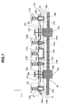
- FIG. 7 is a main part sectional view of the medium discharge device in the second embodiment.
- FIG. 7 corresponds to the sectional view along line A-A in FIG. 2 , similarly to FIG. 3 in the first embodiment.
- the medium discharge device in the second embodiment includes a discharge guide 124 corresponding to the discharge guide 24 in the first embodiment.
- the discharge guide 124 includes guide projections 124a to 124e corresponding to the projections 24a to 24e in the first embodiment.
- the guide projections 124a to 124e are disposed slidably in a direction perpendicular to the discharge plane 56, and urged toward the placing surface 31a.
- the guide projections 124a to 124e are disposed separately from each other, and individually urged by respective coil springs 110a to 110e as urging members.
- the image forming apparatus includes guide holding holes 120a to 120e formed in a main body 180 of the image forming apparatus.
- the guide projections 124a to 124e are inserted and held in the guide holding holes 120a to 120e slidably in the direction of the virtual line 57, respectively.
- the guide projections 124a to 124e have restricting portions (or flange portions) 190a to 190e, respectively.
- the restricting portions 190a to 190e abut on the main body 180 at parts around the guide holding holes 120a to 120e, thereby restricting the guide projections 124a to 124e from moving in a projecting direction opposite to arrow F from their normal positions, respectively.
- the guide projections 124a to 124e are in their normal positions, they are pressed against the main body 180 by the coil springs 110a to 110e in the projecting direction.
- Each of the guide projections 124a, 124b, 124d, and 124e is configured to have, in its normal position, a guide surface identical to the guide surface 61 of the projection 24a in FIG. 4 , and a relationship between the guide surface and the nips 51 and 52 identical to the relationship between the guide surface 61 and the nips 51 and 52 in FIG. 4 .
- the guide projection 124c is configured to have, in its normal position, a guide surface identical to the guide surface 62 of the projection 24c in FIG. 5 , and a relationship between the guide surface and the nips 51 and 52 identical to the relationship between the guide surface 62 and the nips 51 and 52 in FIG. 5 .
- the recording sheet 40 is discharged through the nips 51 and 52 along the discharge plane 56 obliquely upward in the direction of arrow G ( FIG. 2 ) in a state where the sheet cross-section 40a is deformed in a wave shape, in the same manner as the first embodiment.
- the guide projections 124a to 124e are slidably urged by the respective coil springs 110a to 110e.
- each of the guide projections 124a to 124e moves in a retreating direction opposite to the projecting direction to vary its height from the discharge plane 56 in the projecting direction, thereby adjusting a degree of increase of the stiffness.
- the height of the guide projection 124a is at its maximum when the guide projection 124a is in its normal position, and decreases as the guide projection 124a moving in the retreating direction from its normal position.
- the normal position is also referred to as the maximum height position.
- the other guide projections 124b to 124e When the guide projections 124a to 124e are in their normal positions, they bend the recording sheet 40 maximally. That is, when the recording sheet 40 is guided by the guide projections 124a to 124e in their normal positions, the recording sheet 40 is discharged in a maximum bending state where it is maximally bent.
- the recording sheet is a thin paper sheet with low stiffness
- its stiffness needs to be increased.
- the recording sheet with low stiffness since the coil springs 110a to 110e do not deform and the guide projections 124a to 124e stay in their normal positions (maximum height positions), the recording sheet is discharged in a state where it is maximally bent and its stiffness is maximally increased.
- the recording sheet is maximally bent, since the stiffness of the recording sheet itself is low, flaws and wrinkles are difficult to occur.
- the recording sheet is a thick paper sheet with high stiffness
- its stiffness since its leading edge is difficult to sag during discharge, its stiffness does not need to be increased much.
- the recording sheet with high stiffness presses the guide projections 124a to 124e down in the retreating direction from their normal positions (maximum height positions) against the urging force of the coil springs 110a to 110e, lowering the heights of the guide projections 124a to 124e. Therefore, the recording sheet is discharged in a state where it is less bent. If the recording sheet with high stiffness were to be forcibly bent, flaws and wrinkles would occur.
- the configuration of this embodiment can prevent such problems.
- the guide projections 124a to 124e are formed separately from each other and individually urged by the coil springs, the guide projections 124a to 124e may be formed integrally, and the whole of the guide projections 124a to 124e may be urged by only one coil spring or urging member, for example.
- the medium discharge device in this embodiment adjusts the amount of bending of the recording sheet depending on the stiffness of the recording sheet so that the higher the stiffness, the smaller the amount of bending, and prevents a recording sheet with high stiffness (e.g., a thick paper sheet) from being bent more than necessary.
- this embodiment can provide the same advantages as in the first embodiment without causing flaws and wrinkles on the recording sheet.
- parallel is intended to include not only completely parallel but also substantially parallel
- perpendicular is intended to include not only completely perpendicular but also substantially perpendicular
- the LED head is used as an exposure unit of the image forming apparatus
- a laser exposure unit including a small-sized laser and a polygon mirror may be used.
- the above embodiments illustrate an image forming apparatus using a direct transfer system
- the invention is applicable to an image forming apparatus using an intermediate transfer belt.
- the above embodiments exemplify a printer as an image forming apparatus, but the invention is applicable to a copier, a facsimile machine, or other image forming apparatus.
Landscapes
- Engineering & Computer Science (AREA)
- Mechanical Engineering (AREA)
- Physics & Mathematics (AREA)
- General Physics & Mathematics (AREA)
- Separation, Sorting, Adjustment, Or Bending Of Sheets To Be Conveyed (AREA)
- Feeding Of Articles By Means Other Than Belts Or Rollers (AREA)
- Pile Receivers (AREA)
- Delivering By Means Of Belts And Rollers (AREA)
Abstract
Description
- The present invention relates to a medium discharge device for discharging a medium, such as a recording medium after printing, outside an apparatus, and an image forming apparatus including the medium discharge device.
- A general image forming apparatus, such as a copier, a facsimile machine, and a scanner, includes a conveying path on which recording media are conveyed, discharge rollers for discharging the recording media outside the image forming apparatus, and a stacker on which the discharged recording media are stacked (for example, see Japanese Patent Application Publication No.
2012-93648 - As the number of recording media stackable on the stacker increases, the distance from the discharge rollers to the stacker increases, and the possibility of improper stacking due to sagging of the leading edge of the recording medium during discharge increases.
- An aspect of the present invention is intended to reduce the occurrence of improper discharge of a medium.
- According to an aspect of the present invention, there is provided a medium discharge device including: a discharge tray having a placing surface on which a medium is to be placed; a first pair of discharge rollers configured to form a first nip between the first pair of discharge rollers, and rotate about respective axes parallel to each other to discharge the medium through the first nip in a discharging direction onto the discharge tray; a second pair of discharge rollers configured to form a second nip between the second pair of discharge rollers, and rotate about the respective axes to discharge the medium through the second nip in the discharging direction onto the discharge tray; and a discharge guide for guiding the medium discharged by the first pair of discharge rollers and the second pair of discharge rollers. The discharge guide includes: a first projection disposed between the first pair of discharge rollers and the second pair of discharge rollers in an axial direction parallel to the axes, the first projection projecting to the placing surface side relative to the first and second nips and having a first guide surface opposite to the placing surface; and a second projection disposed on an opposite side of the first projection with respect to the first pair of discharge rollers in the axial direction, the second projection projecting to the placing surface side relative to the first and second nips and having a second guide surface opposite to the placing surface.
- According to an another aspect of the present invention, there is provided an image forming apparatus including the above described medium discharge device.
- Further scope of applicability of the present invention will become apparent from the detailed description given hereinafter. However, it should be understood that the detailed description and specific embodiments, while indicating preferred embodiments of the invention, are given by way of illustration only, since various changes and modifications within the spirit and scope of the invention will become apparent to those skilled in the art from this detailed description.
- In the attached drawings:
-
FIG. 1 is a schematic view showing a configuration of an image forming apparatus including a medium discharge device in a first embodiment of the invention; -
FIG. 2 is an enlarged partial sectional view showing the medium discharge device inFIG. 1 ; -
FIG. 3 is a main part sectional view along line A-A inFIG. 2 ; -
FIG. 4 is a sectional view along line B-B inFIG. 3 ; -
FIG. 5 is a sectional view along line C-C inFIG. 3 ; -
FIG. 6 is a sectional view along line D-D inFIG. 3 ; -
FIG. 7 is a main part sectional view of a medium discharge device in a second embodiment of the invention; and -
FIG. 8 is a sectional view of a medium discharge device as a comparative example. - Embodiments of the invention will now be described with reference to the attached drawings.
-
FIG. 1 is a schematic view showing a configuration of an image forming apparatus 1 including a medium discharge device in the first embodiment. - As shown in
FIG. 1 , the image forming apparatus 1 includes fourimage forming units transfer unit 27, asheet cassette 25, asheet feeding roller 11, anentrance sensor 12, awriting sensor 13,conveying rollers fixing unit 28, and amedium discharge device 70. - The
image forming units image forming units LED heads photosensitive drums charging rollers rollers blades sponge rollers - The
sheet cassette 25 stores recording sheets (e.g., sheets of paper) 40 as media. Thesheet feeding roller 11 picks up and feeds therecording sheets 40 one by one from thesheet cassette 25 into a conveying path by cooperating with a separation member (not shown). Theconveying rollers recording sheet 40 to thetransfer unit 27. Thetransfer unit 27 includes anendless conveying belt 18, a belt drivenroller 16, abelt driving roller 17, andtransfer rollers conveying belt 18 conveys therecording sheet 40 from theconveying rollers transfer rollers image forming unit recording sheet 40 conveyed on theconveying belt 18, respectively. Thefixing unit 28 applies heat and pressure to therecording sheet 40 with the toner images transferred thereon to fix the toner images to therecording sheet 40. Thefixing unit 28 includes afixing roller 19 having a heater such as a halogen lamp therein and afixing backup roller 20. Themedium discharge device 70 includes afirst discharge roller 22, asecond discharge roller 23, adischarge guide 24, and adischarge tray 31. The first andsecond discharge rollers recording sheet 40 after the fixing. Thedischarge guide 24 guides therecording sheet 40 discharged by the first andsecond discharge rollers discharge tray 31 stacks therecording sheet 40 discharged by the first andsecond discharge rollers discharge tray 31 has a placingsurface 31a on which therecording sheet 40 is placed. - In the image forming apparatus 1, the
recording sheet 40 is conveyed on the conveying path in a conveying direction. The image forming apparatus 1 further includes motors for rotating the rollers and other rotating members, rollers disposed on the conveying path at intervals not longer than a length of a minimum recording sheet in the conveying direction, a solenoid for switching the conveying path, or the like, which are not shown inFIG. 1 . The motors includes a sheet feeding motor for mainly rotating thesheet feeding roller 11, a conveying motor for rotating theconveying rollers belt driving roller 17, a fixing motor for rotating thefixing roller 19, thefixing backup roller 20, and thedischarge rollers image forming units - In
FIG. 1 , the X-axis represents a direction in which therecording sheet 40 is conveyed when passing through theimage forming units photosensitive drums FIGs 2 to 7 . Here, the image forming apparatus 1 is set so that the Z-axis is directed in a substantially vertical direction. - Next, a configuration of the
medium discharge device 70 will be described with reference toFIGs. 2 to 6 . -
FIG. 2 is an enlarged partial sectional view showing themedium discharge device 70 inFIG. 1 .FIG. 3 is a main part sectional view along line A-A inFIG. 2 .FIG. 4 is a sectional view along line B-B inFIG. 3 .FIG. 5 is a sectional view along line C-C inFIG. 3 .FIG. 6 is a sectional view along line D-D inFIG. 3 . - As shown in
FIG. 2 , thefirst discharge roller 22, thesecond discharge roller 23, thedischarge guide 24, and thedischarge tray 31 are attached to amain body 80 of the image forming apparatus 1. Themain body 80 has aguide portion 81 for guiding therecording sheet 40 from thefixing unit 28. Thefirst discharge roller 22 has an axis of rotation A1 (referred to below simply as the axis A1) parallel to the Y-axis. Thesecond discharge roller 23 has an axis of rotation A2 (referred to below simply as the axis A2) parallel to the Y-axis. As described later, thefirst discharge roller 22 and thesecond discharge roller 23 are disposed to form nips between their peripheral surfaces. Thefirst discharge roller 22 and thesecond discharge roller 23 discharge therecording sheet 40 in a discharging direction (indicated by arrow G inFIG. 2 ), which is perpendicular to a virtual line 57 (indicated by the dashed-dotted line inFIG. 2 ) perpendicularly intersecting the axes A1 and A2. The discharging direction (i.e., the direction of arrow G) is directed obliquely upward. Here, thefirst discharge roller 22 is disposed below thesecond discharge roller 23 and on a discharge side (or thedischarge tray 31 side) of thesecond discharge roller 23 in a horizontal direction. - As shown in
FIG. 3 , thesecond discharge roller 23 includes a pair ofroller portions roller portions roller portions shafts first discharge roller 22 has ashaft 22c parallel to theshafts second discharge roller 23, and a pair ofroller portions shaft 22c so as to face the pair ofroller portions second discharge roller 23. Theroller portions roller portions roller portions roller portions roller portions roller portions - Here, the
first discharge roller 22 receives rotational force to rotate in a direction for discharging therecording sheet 40, and the pair ofroller portions second discharge roller 23 are rotated by the rotation of thefirst discharge roller 22 by friction with thefirst discharge roller 22 either directly or via therecording sheet 40. That is, thefirst discharge roller 22 is a driving roller and thesecond discharge roller 23 is a driven roller. Theroller portions recording sheet 40 through thenip 51 onto thedischarge tray 31. Theroller portions recording sheet 40 through thenip 52 onto thedischarge tray 31. The first pair of discharge rollers and the second pair of discharge rollers rotate together about respective axes A1 and A2 to discharge therecording sheet 40 through thenips discharge tray 31. The first pair of discharge rollers and the second pair of discharge rollers are at positions different from each other in the direction of the axes A1 and A2, and define a discharge plane 56 (indicated by the dashed-dotted line inFIG. 3 ) passing through thenips virtual line 57 extending along the direction of arrow F. - The
discharge guide 24 includes a plurality of projections: aprojection 24a as a second projection, aprojection 24b as a fourth projection, aprojection 24c as a first projection, aprojection 24d as a fifth projection, and aprojection 24e as a third projection. Theprojections 24a to 24e are arranged in the Y-axis direction. Each of theprojections 24a to 24e projects to the placingsurface 31a side relative to thenips projections 24a to 24e projects from an opposite side of the placingsurface 31a to the placingsurface 31a side relative to thenips discharge plane 56. Each of theprojections guide surface 61 opposite to the placingsurface 31a, and theprojection 24c has aguide surface 62 opposite to the placingsurface 31a. Each of the guide surfaces 61 and 62 is located at the placingsurface 31a side end of the corresponding projection. AlthoughFIG. 3 illustrates thedischarge guide 24 as comprising three separate parts, thedischarge guide 24 is actually formed integrally. - The
projection 24c is disposed between theroller portion 22a (or the first pair of discharge rollers) and theroller portion 22b (or the second pair of discharge rollers) in the Y-axis direction (referred to also as the axial direction) parallel to the axes A1 and A2. Theprojection 24a is disposed on an opposite side of theprojection 24c with respect to theroller portion 22a (or the first pair of discharge rollers) in the Y-axis direction. Theprojection 24e is disposed on an opposite side of theprojection 24c with respect to theroller portion 22b (or the second pair of discharge rollers) in the Y-axis direction. Theprojection 24b is disposed between theprojection 24c and theroller portion 22a (or the first pair of discharge rollers) in the Y-axis direction. Theprojection 24d is disposed between theprojection 24c and theroller portion 22b (or the second pair of discharge rollers) in the Y-axis direction. Specifically, theprojections 24a to 24e are formed plane-symmetrically with respect to avirtual center plane 55 perpendicular to the Y-axis and passing through the center between thenips projections 24a to 24e are configured as follows: theprojection 24c is located at the center portion and wider than theother projections projections projection 24c and have the same width narrower than that of theprojection 24c; theprojection 24a is located on the outer side of theprojection 24b across thenip 51; theprojection 24e is located on the outer side of theprojection 24d across thenip 52; and theprojections projection 24c and wider than those of theprojections - The
projections projection 24a will now be representatively described with reference toFIG. 4 showing the cross-section of theprojection 24a. - In
FIG. 4 , the dashed-dotted line in the direction of arrow F indicates thevirtual line 57 perpendicularly intersecting the axis A1 of thefirst discharge roller 22 and the axis A2 of thesecond discharge roller 23. The dashed-dotted line in the direction of arrow G indicates thedischarge plane 56 perpendicular to thevirtual line 57 and passing through thenips first discharge roller 22 and thesecond discharge roller 23 convey and discharge therecording sheet 40 along thedischarge plane 56 in the direction of arrow G (i.e., the discharging direction) in thenips guide surface 61 extends from an upstream side to a downstream side of thenip 51 in the discharging direction, and includes aninlet surface 61a located upstream of thenip 51 and anoutlet surface 61b located downstream of thenip 51. Theguide portion 81 of the main body 80 (seeFIG. 2 ) has aguide surface 33 below theguide surface 61. On the upstream side of and in the vicinity of thenip 51 in the conveying direction, theguide surface 61 and theguide surface 33 in combination form the conveying path. Theprojection 24a receives therecording sheet 40 conveyed from below in a direction indicated by arrow H, and guides the leading edge of the conveyedrecording sheet 40 along the conveying path toward thenip 51. - As shown in
FIG. 4 , when viewed from the Y-axis direction, theinlet surface 61a is disposed generally along and slightly below the discharge plane 56 (on theroller portion 22a side). Theinlet surface 61a curves so as to separate from thedischarge plane 56 as approaching thenip 51, and projects downward (to theroller portion 22a side) from thenip 51 by a predetermined amount on thevirtual line 57. - On the downstream side of the
nip 51, theguide surface 61 is inclined to thedischarge plane 56 so as to approach thedischarge plane 56 downstream in the discharging direction, or parallel to thedischarge plane 56. In the example ofFIG. 4 , theoutlet surface 61b is formed continuously to theinlet surface 61a, and extends to slightly approach thedischarge plane 56 as separating from thenip 51. Theoutlet surface 61b may be parallel to thedischarge plane 56. The angle formed between theoutlet surface 61b and thedischarge plane 56 is preferably 0° to 10°. The same applies to theprojections projections guide surface 61 and a positional relationship between theguide surface 61 and thedischarge plane 56, in the same manner as theprojection 24a. - Next, the shape of the
projection 24c will be described with reference toFIG. 5 showing the cross-section of theprojection 24c. - In
FIG. 5 , the dashed-dotted line in the direction of arrow F indicates thevirtual line 57, and the dashed-dotted line in the direction of arrow G indicates thedischarge plane 56. Theguide surface 62 extends from the upstream side to the downstream side of thenip 52 in the discharging direction, and includes aninlet surface 62a located upstream of thenip 52 and anoutlet surface 62b located downstream of thenip 52. On the upstream side of and in the vicinity of thenip 52 in the conveying direction, theguide surface 62 forms the conveying path with theguide surface 33 disposed below theguide surface 62. Theprojection 24c receives therecording sheet 40 conveyed from below in the direction of arrow H, and guides the leading edge of the conveyedrecording sheet 40 along the conveying path toward thenips - As shown in
FIG. 5 , when viewed from the Y-axis direction, theinlet surface 62a is disposed generally along and slightly below the discharge plane 56 (on theroller portion 22b side). Theinlet surface 62a curves so as to separate from thedischarge plane 56 as approaching thenip 52, and projects downward (to theroller portion 22b side) from thenip 52 by a predetermined amount on thevirtual line 57. That is, in this embodiment, on the upstream side of thenip 52, theinlet surface 62a of theguide surface 62 of theprojection 24c is formed in the same manner as theinlet surface 61a of theguide surface 61 of theprojection 24a. - On the downstream side of the
nip 52, theguide surface 62 has an inclinedarea 62d inclined with respect to thedischarge plane 56 so as to separate from thedischarge plane 56 downstream in the discharging direction. In the example ofFIG. 5 , theoutlet surface 62b is formed continuously to theinlet surface 62a and has the inclinedarea 62d. Theinclined area 62d is formed continuously to theinlet surface 62a and curves so as to separate from thedischarge plane 56 as it extends downstream in the discharging direction. Further, theoutlet surface 62b has anend area 62c formed continuously to theinclined area 62d so as to extend parallel to thedischarge plane 56. Thus, theoutlet surface 62b further projects downward (to theroller portion 22b side) relative to the position on thevirtual line 57. - As shown in
FIGs. 4 and5 , a difference between a projecting amount by which theprojection 24c projects to the placingsurface 31a side relative to the nip 51 and a projecting amount by which theprojection 24a projects to the placingsurface 31a side relative to the nip 51 increases downstream from thenip 51 in the discharging direction. The projecting amount of theprojection 24c is, for example, defined as a distance from thedischarge plane 56 to theguide surface 62 in the direction of thevirtual line 57. The projecting amount of theprojection 24a is, for example, defined as a distance from thedischarge plane 56 to theguide surface 61 in the direction of thevirtual line 57. - Further, as shown in
FIGs. 4 and5 , a first projecting amount by which a downstream end in the discharging direction of theprojection 24c projects to the placingsurface 31a side relative to the nip 51 is greater than a second projecting amount by which a downstream end in the discharging direction of theprojection 24a projects to the placingsurface 31a side relative to thenip 51. The first projecting amount is, for example, defined as a distance from thedischarge plane 56 to a downstream end of theguide surface 62 in the direction of thevirtual line 57. The second projecting amount is, for example, defined as a distance from thedischarge plane 56 to a downstream end of theguide surface 61 in the direction of thevirtual line 57. - Next, a configuration in the vicinity of the
nip 52 will be described with reference toFIG. 6 showing a cross-section at the roller facing portion at which theroller portion 22b of thefirst discharge roller 22 and theroller portion 23b of thesecond discharge roller 23 form thenip 52. - In
FIG. 6 , the dashed-dotted line in the direction of arrow F indicates thevirtual line 57, and the dashed-dotted line in the direction of arrow G indicates thedischarge plane 56. Referring toFIG. 3 , thedischarge guide 24 does not exist in the vicinity of the roller facing portion. As shown inFIG. 6 , on the upstream side of thenip 52 in the conveying direction, theguide surface 33 forms the conveying path with aguide surface 34 of theguide portion 81 of themain body 80 so as to extend to the vicinity of thenip 52. - The leading edge of the
recording sheet 40 conveyed from below in the direction of arrow H is guided by the guide surfaces 33 and 34 along the conveying path, and then becomes free (or unguided) near thenip 52. Meanwhile, as described above, the leading edge of therecording sheet 40 is guided below thedischarge plane 56 by theprojections 24a to 24e of thedischarge guide 24. Thus, the leading edge of therecording sheet 40 moves in abutment on thelower guide surface 33 or theroller portion 22b of thefirst discharge roller 22 to thenip 52. - A configuration in the vicinity of the
nip 51 is the same as that in the vicinity of thenip 52, and the description thereof will be omitted. - An operation of the above described
medium discharge device 70 will be described below. - Referring to
FIG. 1 , the fixingunit 28 performs fixing processing on arecording sheet 40, which is conveyed through a conveyingpath 21 shown inFIG. 2 . Referring toFIGs. 4 and5 , therecording sheet 40 is conveyed in the direction of arrow H, and then the leading edge of therecording sheet 40 abuts on and is guided by the inlet surfaces 61a and 62a (having the same cross-sectional shape) of theprojections 24a to 24e of thedischarge guide 24 toward thenips - At this time, as shown in
FIGs. 4 and5 , when viewed from the Y-axis direction, therecording sheet 40 is maintained generally below the discharge plane 56 (on thefirst roller 22 side) by the inlet surfaces 61a and 62a of theprojections 24a to 24e, and guided so as to separate from thedischarge plane 56 as approaching thenips first roller 22 side) by a predetermined amount relative to thenips virtual line 57. -
FIG. 3 shows asheet cross-section 40a of therecording sheet 40 at the position of thenips FIG. 3 , when therecording sheet 40 is nipped in thenips first discharge roller 22 side from thedischarge plane 56 between thenips projections nip 51 by theprojection 24a, and on the outer side of thenip 52 by theprojection 24e. Thus, therecording sheet 40 is bent to have a wave-shaped cross-section. - When the
recording sheet 40 is conveyed toward thenips projections 24a to 24e and theroller portions first discharge roller 22, until it reaches thenips recording sheet 40 can be bent so that itscross-section 40a at the position of thenips recording sheet 40. - On the other hand, on the downstream side of the
nips recording sheet 40 moves while nipped in thenips projections nips recording sheet 40 to forcibly deform the shape of thesheet cross-section 40a at the position of thenips 51 and 52 (e.g., increase the protrusion of the recording sheet 40). If theprojections recording sheet 40 to forcibly deform the shape of thesheet cross-section 40a on the downstream side of and in the vicinity of thenips recording sheet 40 would be subjected to excessive stress, which causing wrinkles and flaws on therecording sheet 40. - Thus, regarding the
projections FIG. 4 , theoutlet surface 61b on the downstream side of thenips discharge plane 56 as it extends downstream, or parallel to thedischarge plane 56. It is noted that since theoutlet surface 61b extends downstream continuously to theinlet surface 61a, the leading edge of the recording sheet is prevented from, immediately after passing through thenips discharge rollers - On the other hand, regarding the
projection 24c, which is disposed relatively away from thenips projections nips 51 and 52), as shown inFIG. 5 , theoutlet surface 62b on the downstream side of thenips discharge plane 56 as it extends downstream, pressing therecording sheet 40 to prevent slack of therecording sheet 40 on the downstream side of thenips recording sheet 40 uniformly in the left-right direction (the Y-axis direction). - Thus, the
recording sheet 40 is discharged from thenips discharge plane 56 obliquely upward in the direction of arrow G (FIG. 2 ) in a state where thesheet cross-section 40a is deformed in a wave shape. This wave shape of thesheet cross-section 40a has, as shown inFIG. 3 , three concave/convex portions (specifically, one concave portion and two convex portions), which increase the stiffness of therecording sheet 40. Therefore, therecording sheet 40 is discharged and falls onto thedischarge tray 31 while maintaining a state where its leading edge is difficult to sag due to its own weight. The term "concave/convex portion" means a portion forming either a concave or a convex. - The discharged
recording sheet 40 is received and held on the placingsurface 31a of thedischarge tray 31. The placingsurface 31a faces upward, and here extends parallel to thedischarge plane 56. The guide surfaces 61 and 62 of thedischarge guide 24 are disposed generally along thedischarge plane 56 to face downward, therefore opposing the placingsurface 31a vertically (more accurately, in the direction of the virtual line 57). -
FIG. 8 is a sectional view of a medium discharge device as a comparative example, which is the same as themedium discharge device 70 except for having adischarge guide 224 different in shape from thedischarge guide 24 in the embodiment. - As shown in
FIG. 8 , between thenips discharge guide 224 presses down therecording sheet 40 below thedischarge plane 56 to form a protrusion in therecording sheet 40, similarly to thedischarge guide 24 of the embodiment. However, on the outer side of thenip 51 and the outer side of thenip 52, theprojections recording sheet 40 down, and form no protrusion in therecording sheet 40. Thus, although therecording sheet 40 is discharged from thenips discharge plane 56 obliquely upward in the direction of arrow G (FIG. 2 ) in a state where thesheet cross-section 40a is deformed in a wave shape in the width direction, the wave shape of thesheet cross-section 40a has only one concave/convex portion (specifically, only one concave portion), as shown inFIG. 8 . - Thus, in the comparative example, compared to the embodiment, the discharged
recording sheet 40 has a low stiffness and is easy to sag during discharging or falling onto thedischarge tray 31, and improper discharge, such as page disorder, page missing, and sheet curl, is likely to occur. The stiffness of therecording sheet 40 in the comparative example can be increased by making the protrusion higher or closer to thenips recording sheet 40 due to deformation, causing flaws or wrinkles on therecording sheet 40. - As described above, the medium discharge device in this embodiment discharges the recording sheet while increasing the stiffness of the recording sheet by deforming the recording sheet in a wave surface shape to form multiple concave/convex portions, thereby reducing improper discharge (or improper stacking), such as page disorder, page missing, and sheet curl, even if the distance by which the recording sheet falls down to the placing surface is large. Further, the medium discharge device in this embodiment can reduce the occurrence of flaws, wrinkles, or the like caused by making the protrusion higher or wider.
- Although in this embodiment, the
projection 24b is disposed between theprojection 24c and thenip 51 and theprojection 24d is disposed between theprojection 24c and thenip 52, either or both of theprojections projection 24c or the shape of theoutlet surface 62b of theprojection 24c so as to reduce the slack of therecording sheet 40 on the downstream side of thenips - Further, although in this embodiment, the
projection 24a is disposed on the end side of thenip 51 and theprojection 24e is disposed on the end side of thenip 52, either theprojection - An image forming apparatus in the second embodiment will be described below. This image forming apparatus is substantially the same as in the first embodiment, except for including a medium discharge device different from that in the first embodiment. Thus, descriptions of parts that are the same as in the first embodiment will be omitted or simplified in the description below, and the same reference characters will be used.
-
FIG. 7 is a main part sectional view of the medium discharge device in the second embodiment.FIG. 7 corresponds to the sectional view along line A-A inFIG. 2 , similarly toFIG. 3 in the first embodiment. - The medium discharge device in the second embodiment includes a
discharge guide 124 corresponding to thedischarge guide 24 in the first embodiment. Thedischarge guide 124 includesguide projections 124a to 124e corresponding to theprojections 24a to 24e in the first embodiment. Theguide projections 124a to 124e are disposed slidably in a direction perpendicular to thedischarge plane 56, and urged toward the placingsurface 31a. Theguide projections 124a to 124e are disposed separately from each other, and individually urged by respective coil springs 110a to 110e as urging members. - As shown in
FIG. 7 , the image forming apparatus. includesguide holding holes 120a to 120e formed in amain body 180 of the image forming apparatus. Theguide projections 124a to 124e are inserted and held in theguide holding holes 120a to 120e slidably in the direction of thevirtual line 57, respectively. Theguide projections 124a to 124e have restricting portions (or flange portions) 190a to 190e, respectively. The restrictingportions 190a to 190e abut on themain body 180 at parts around theguide holding holes 120a to 120e, thereby restricting theguide projections 124a to 124e from moving in a projecting direction opposite to arrow F from their normal positions, respectively. When theguide projections 124a to 124e are in their normal positions, they are pressed against themain body 180 by the coil springs 110a to 110e in the projecting direction. - Each of the
guide projections guide surface 61 of theprojection 24a inFIG. 4 , and a relationship between the guide surface and thenips guide surface 61 and thenips FIG. 4 . - The
guide projection 124c is configured to have, in its normal position, a guide surface identical to theguide surface 62 of theprojection 24c inFIG. 5 , and a relationship between the guide surface and thenips guide surface 62 and thenips FIG. 5 . - Therefore, when the
guide projections 124a to 124e are in their normal positions, therecording sheet 40 is discharged through thenips discharge plane 56 obliquely upward in the direction of arrow G (FIG. 2 ) in a state where thesheet cross-section 40a is deformed in a wave shape, in the same manner as the first embodiment. - In this embodiment, the
guide projections 124a to 124e are slidably urged by the respective coil springs 110a to 110e. Thus, when therecording sheet 40 is discharged, depending on the stiffness of therecording sheet 40 itself, each of theguide projections 124a to 124e moves in a retreating direction opposite to the projecting direction to vary its height from thedischarge plane 56 in the projecting direction, thereby adjusting a degree of increase of the stiffness. Specifically, the height of theguide projection 124a is at its maximum when theguide projection 124a is in its normal position, and decreases as theguide projection 124a moving in the retreating direction from its normal position. The normal position is also referred to as the maximum height position. The same is true for theother guide projections 124b to 124e. When theguide projections 124a to 124e are in their normal positions, they bend therecording sheet 40 maximally. That is, when therecording sheet 40 is guided by theguide projections 124a to 124e in their normal positions, therecording sheet 40 is discharged in a maximum bending state where it is maximally bent. - More specifically, when the recording sheet is a thin paper sheet with low stiffness, since its leading edge is easy to sag during discharge, its stiffness needs to be increased. When the recording sheet with low stiffness is discharged, since the coil springs 110a to 110e do not deform and the
guide projections 124a to 124e stay in their normal positions (maximum height positions), the recording sheet is discharged in a state where it is maximally bent and its stiffness is maximally increased. In this case, although the recording sheet is maximally bent, since the stiffness of the recording sheet itself is low, flaws and wrinkles are difficult to occur. - On the other hand, when the recording sheet is a thick paper sheet with high stiffness, since its leading edge is difficult to sag during discharge, its stiffness does not need to be increased much. When the recording sheet with high stiffness is discharged, the recording sheet presses the
guide projections 124a to 124e down in the retreating direction from their normal positions (maximum height positions) against the urging force of the coil springs 110a to 110e, lowering the heights of theguide projections 124a to 124e. Therefore, the recording sheet is discharged in a state where it is less bent. If the recording sheet with high stiffness were to be forcibly bent, flaws and wrinkles would occur. The configuration of this embodiment can prevent such problems. - Although in this embodiment, the
guide projections 124a to 124e are formed separately from each other and individually urged by the coil springs, theguide projections 124a to 124e may be formed integrally, and the whole of theguide projections 124a to 124e may be urged by only one coil spring or urging member, for example. - As described above, the medium discharge device in this embodiment adjusts the amount of bending of the recording sheet depending on the stiffness of the recording sheet so that the higher the stiffness, the smaller the amount of bending, and prevents a recording sheet with high stiffness (e.g., a thick paper sheet) from being bent more than necessary. Thus, this embodiment can provide the same advantages as in the first embodiment without causing flaws and wrinkles on the recording sheet.
- In this specification, the term "parallel" is intended to include not only completely parallel but also substantially parallel, and the term "perpendicular" is intended to include not only completely perpendicular but also substantially perpendicular.
- While the preferred embodiments of the present invention have been illustrated in detail, it should be apparent that modifications and improvements may be made to the invention without departing from the spirit and scope of the invention as described in the following claims.
- For example, although in the above embodiments, the LED head is used as an exposure unit of the image forming apparatus, a laser exposure unit including a small-sized laser and a polygon mirror may be used. Further, although the above embodiments illustrate an image forming apparatus using a direct transfer system, the invention is applicable to an image forming apparatus using an intermediate transfer belt. Furthermore, the above embodiments exemplify a printer as an image forming apparatus, but the invention is applicable to a copier, a facsimile machine, or other image forming apparatus.
Claims (13)
- A medium discharge device (70) comprising:a discharge tray (31) having a placing surface (31a) on which a medium (40) is to be placed;a first pair of discharge rollers (22a, 23a) configured to form a first nip (51) between the first pair of discharge rollers (22a, 23a), and rotate about respective axes (A1, A2) parallel to each other to discharge the medium (40) through the first nip (51) in a discharging direction (G) onto the discharge tray (31);a second pair of discharge rollers (22b, 23b) configured to form a second nip (52) between the second pair of discharge rollers (22b, 23b), and rotate about the respective axes (A1, A2) to discharge the medium (40) through the second nip (52) in the discharging direction (G) onto the discharge tray (31); anda discharge guide (24, 124) for guiding the medium (40) discharged by the first pair of discharge rollers (22a, 23a) and the second pair of discharge rollers (22b, 23b), the discharge guide (24, 124) including:a first projection (24c, 124c) disposed between the first pair of discharge rollers (22a, 23a) and the second pair of discharge rollers (22b, 23b) in an axial direction (Y) parallel to the axes (A1, A2), the first projection (24c, 124c) projecting to the placing surface (31a) side relative to the first and second nips (51, 52) and having a first guide surface (62) opposite to the placing surface (31a); anda second projection (24a, 124a) disposed on an opposite side of the first projection (24c, 124c) with respect to the first pair of discharge rollers (22a, 23a) in the axial direction (Y), the second projection (24a, 124a) projecting to the placing surface (31a) side relative to the first and second nips (51, 52) and having a second guide surface (61) opposite to the placing surface (31a).
- The medium discharge device (70) of claim 1, wherein each of the first and second guide surfaces (61, 62) extends from an upstream side to a downstream side of the first and second nips (51, 52) in the discharging direction (G).
- The medium discharge device (70) of claim 2, wherein on the downstream side of the first and second nips (51, 52), the second guide surface (61) is parallel to a discharge plane (56) passing through the first and second nips (51, 52) and being perpendicular to a virtual line (57) perpendicularly intersecting the axes (A1, A2), or is inclined to the discharge plane (56) so as to approach the discharge plane (56) downstream in the discharging direction (G).
- The medium discharge device (70) of claim 2 or 3, wherein on the downstream side of the first and second nips (51, 52), the first guide surface (62) has an area (62d) inclined to a discharge plane (56) passing through the first and second nips (51, 52) and being perpendicular to a virtual line (57) perpendicularly intersecting the axes (A1, A2) so as to separate from the discharge plane (56) downstream in the discharging direction (G).
- The medium discharge device (70) of any one of claims 1 to 4, wherein a difference between a projecting amount by which the first projection (24c, 124c) projects to the placing surface (31a) side relative to the first nip (51) and a projecting amount by which the second projection (24a, 124a) projects to the placing surface (31a) side relative to the first nip (51) increases downstream from the first nip (51) in the discharging direction (G).
- The medium discharge device (70) of any one of claims 1 to 5, wherein a first projecting amount by which a downstream end in the discharging direction (G) of the first projection (24c, 124c) projects to the placing surface (31a) side relative to the first nip (51) is greater than a second projecting amount by which a downstream end in the discharging direction (G) of the second projection (24a, 124a) projects to the placing surface (31a) side relative to the first nip (51).
- The medium discharge device (70) of any one of claims 1 to 6, wherein the discharge guide (24, 124) further includes a third projection (24e, 124e) disposed on an opposite side of the first projection (24c, 124c) with respect to the second pair of discharge rollers (22b, 23b) in the axial direction (Y), the third projection (24e, 124e) projecting to the placing surface (31a) side relative to the first and second nips (51, 52) and having a third guide surface (61) opposite to the placing surface (31a).
- The medium discharge device (70) of claim 7, wherein the discharge guide (24, 124) further includes:a fourth projection (24b, 124b) disposed between the first projection (24c, 124c) and the first pair of discharge rollers (22a, 23a) in the axial direction (Y), the fourth projection (24b, 124b) projecting to the placing surface (31a) side relative to the first and second nips (51, 52) and having a fourth guide surface (61) opposite to the placing surface (31a); anda fifth projection (24d, 124d) disposed between the first projection (24c, 124c) and the second pair of discharge rollers (22b, 23b) in the axial direction (Y), the fifth projection (24d, 124d) projecting to the placing surface (31a) side relative to the first and second nips (51, 52) and having a fifth guide surface (61) opposite to the placing surface (31a).
- The medium discharge device (70) of claim 8, wherein each of the third to fifth guide surfaces (61) extends from an upstream side to a downstream side of the first and second nips (51, 52) in the discharging direction (G).
- The medium discharge device (70) of claim 9, wherein on the downstream side of the first and second nips (51, 52), each of the third to fifth guide surfaces (61) is parallel to a discharge plane (56) passing through the first and second nips (51, 52) and being perpendicular to a virtual line (57) perpendicularly intersecting the axes (A1, A2), or is inclined to the discharge plane (56) so as to approach the discharge plane (56) downstream in the discharging direction (G).
- The medium discharge device (70) of any one of claims 1 to 10, wherein the projections (24a to 24e, 124a to 124e) in the discharge guide (24, 124) are disposed slidably in a direction perpendicular to a discharge plane (56) passing through the first and second nips (51, 52) and being perpendicular to a virtual line (57) perpendicularly intersecting the axes (A1, A2), and urged toward the placing surface (31a).
- The medium discharge device (70) of claim 11, wherein the projections (24a to 24e, 124a to 124e) in the discharge guide (24, 124) are formed separately from each other and individually urged.
- An image forming apparatus (1) comprising the medium discharge device (70) of any one of claims 1 to 12.
Applications Claiming Priority (1)
| Application Number | Priority Date | Filing Date | Title |
|---|---|---|---|
| JP2013133707A JP5847125B2 (en) | 2013-06-26 | 2013-06-26 | Medium discharging apparatus and image forming apparatus |
Publications (3)
| Publication Number | Publication Date |
|---|---|
| EP2818934A2 true EP2818934A2 (en) | 2014-12-31 |
| EP2818934A3 EP2818934A3 (en) | 2015-02-18 |
| EP2818934B1 EP2818934B1 (en) | 2019-08-07 |
Family
ID=50943217
Family Applications (1)
| Application Number | Title | Priority Date | Filing Date |
|---|---|---|---|
| EP14172971.5A Active EP2818934B1 (en) | 2013-06-26 | 2014-06-18 | Medium discharge device and image forming apparatus |
Country Status (4)
| Country | Link |
|---|---|
| US (1) | US9212017B2 (en) |
| EP (1) | EP2818934B1 (en) |
| JP (1) | JP5847125B2 (en) |
| CN (1) | CN104252113B (en) |
Cited By (1)
| Publication number | Priority date | Publication date | Assignee | Title |
|---|---|---|---|---|
| CN111064853A (en) * | 2018-10-17 | 2020-04-24 | 夏普株式会社 | Document conveying device and image forming apparatus |
Families Citing this family (5)
| Publication number | Priority date | Publication date | Assignee | Title |
|---|---|---|---|---|
| US9783384B2 (en) | 2015-03-31 | 2017-10-10 | Crane Payment Innovations, Inc. | Bi-modal rollers |
| JP6890949B2 (en) * | 2016-10-26 | 2021-06-18 | キヤノン株式会社 | Sheet ejection device and image forming device |
| JP2018095471A (en) * | 2016-12-16 | 2018-06-21 | キヤノン株式会社 | Sheet conveying apparatus and image forming apparatus |
| JP2024113738A (en) * | 2023-02-10 | 2024-08-23 | セイコーエプソン株式会社 | Media ejection device and image reading device |
| JP2025070842A (en) * | 2023-10-20 | 2025-05-02 | キヤノン株式会社 | Image forming device |
Citations (1)
| Publication number | Priority date | Publication date | Assignee | Title |
|---|---|---|---|---|
| JP2012093648A (en) | 2010-10-28 | 2012-05-17 | Oki Data Corp | Image forming apparatus |
Family Cites Families (11)
| Publication number | Priority date | Publication date | Assignee | Title |
|---|---|---|---|---|
| US5194904A (en) * | 1992-04-15 | 1993-03-16 | Compaq Computer Corporation | Exiting paper deflector apparatus for an image reproduction machine |
| US6190070B1 (en) * | 1998-10-13 | 2001-02-20 | Xerox Corporation | Printer with media corrugation at media output |
| JP2005247442A (en) * | 2004-03-01 | 2005-09-15 | Murata Mach Ltd | Eject roller device |
| JP4391445B2 (en) * | 2005-06-01 | 2009-12-24 | 株式会社リコー | Automatic document feeder and image reading apparatus |
| JP4872471B2 (en) * | 2006-06-12 | 2012-02-08 | 富士ゼロックス株式会社 | Paper discharge device and image forming apparatus |
| JP2010006537A (en) * | 2008-06-26 | 2010-01-14 | Canon Inc | Sheet processing device |
| JP5265599B2 (en) * | 2010-02-26 | 2013-08-14 | 京セラドキュメントソリューションズ株式会社 | Image forming apparatus |
| JP2011184178A (en) * | 2010-03-10 | 2011-09-22 | Fuji Xerox Co Ltd | Paper conveying device, image forming device having the same, image reading device, and post-processing device |
| JP5191526B2 (en) * | 2010-11-16 | 2013-05-08 | シャープ株式会社 | Sheet conveying apparatus and image forming apparatus having the same |
| TWI397498B (en) * | 2010-11-24 | 2013-06-01 | Avision Inc | Sheet de-curling mechanism and printing apparatus using the same |
| JP6186893B2 (en) * | 2013-05-31 | 2017-08-30 | ブラザー工業株式会社 | Image forming apparatus |
-
2013
- 2013-06-26 JP JP2013133707A patent/JP5847125B2/en not_active Expired - Fee Related
-
2014
- 2014-06-18 EP EP14172971.5A patent/EP2818934B1/en active Active
- 2014-06-25 US US14/314,772 patent/US9212017B2/en not_active Expired - Fee Related
- 2014-06-26 CN CN201410291628.1A patent/CN104252113B/en not_active Expired - Fee Related
Patent Citations (1)
| Publication number | Priority date | Publication date | Assignee | Title |
|---|---|---|---|---|
| JP2012093648A (en) | 2010-10-28 | 2012-05-17 | Oki Data Corp | Image forming apparatus |
Cited By (1)
| Publication number | Priority date | Publication date | Assignee | Title |
|---|---|---|---|---|
| CN111064853A (en) * | 2018-10-17 | 2020-04-24 | 夏普株式会社 | Document conveying device and image forming apparatus |
Also Published As
| Publication number | Publication date |
|---|---|
| CN104252113A (en) | 2014-12-31 |
| US20150001795A1 (en) | 2015-01-01 |
| US9212017B2 (en) | 2015-12-15 |
| JP5847125B2 (en) | 2016-01-20 |
| EP2818934A3 (en) | 2015-02-18 |
| EP2818934B1 (en) | 2019-08-07 |
| CN104252113B (en) | 2018-11-13 |
| JP2015009901A (en) | 2015-01-19 |
Similar Documents
| Publication | Publication Date | Title |
|---|---|---|
| EP2818934B1 (en) | Medium discharge device and image forming apparatus | |
| US9856099B2 (en) | Sheet feeder and image forming apparatus incorporating the sheet feeder | |
| US9625861B2 (en) | Sheet cooling apparatus and image forming apparatus | |
| US11199801B2 (en) | Sheet discharging apparatus having electrostatic charge removal and image forming apparatus | |
| JP2005247442A (en) | Eject roller device | |
| EP3001250A1 (en) | Sheet processing apparatus and image forming apparatus | |
| JP2018066900A (en) | Image heating device | |
| CN102402162B (en) | Fixation unit and image processing system | |
| JP2014199382A (en) | Separation device, and fixing device and image forming apparatus | |
| US11614702B2 (en) | Fixing device | |
| JP2009007080A (en) | Image forming apparatus | |
| US11198581B2 (en) | Sheet processing apparatus and image forming apparatus | |
| JP7317569B2 (en) | Paper transport device and image forming device | |
| CN111908198A (en) | Sheet conveying apparatus, image forming apparatus, method, and storage medium | |
| CN113759686B (en) | Image forming apparatus | |
| US20200409300A1 (en) | Image forming apparatus incorporating decurler | |
| US8544386B2 (en) | Interposer having decurler | |
| EP1965270A1 (en) | Discharge guide and Image forming apparatus having the same | |
| EP4276542A1 (en) | Fixing device and image forming apparatus | |
| US12487544B2 (en) | Fixing apparatus and film unit | |
| US20110058860A1 (en) | Support mechanism for coil tension spring | |
| JP5884379B2 (en) | Medium conveying apparatus and image forming apparatus | |
| US11613440B2 (en) | Sheet conveyance device and image forming apparatus | |
| EP3251991A1 (en) | Image forming apparatus | |
| US20210243318A1 (en) | Image reading apparatus and image forming apparatus |
Legal Events
| Date | Code | Title | Description |
|---|---|---|---|
| PUAI | Public reference made under article 153(3) epc to a published international application that has entered the european phase |
Free format text: ORIGINAL CODE: 0009012 |
|
| 17P | Request for examination filed |
Effective date: 20140618 |
|
| AK | Designated contracting states |
Kind code of ref document: A2 Designated state(s): AL AT BE BG CH CY CZ DE DK EE ES FI FR GB GR HR HU IE IS IT LI LT LU LV MC MK MT NL NO PL PT RO RS SE SI SK SM TR |
|
| AX | Request for extension of the european patent |
Extension state: BA ME |
|
| PUAL | Search report despatched |
Free format text: ORIGINAL CODE: 0009013 |
|
| AK | Designated contracting states |
Kind code of ref document: A3 Designated state(s): AL AT BE BG CH CY CZ DE DK EE ES FI FR GB GR HR HU IE IS IT LI LT LU LV MC MK MT NL NO PL PT RO RS SE SI SK SM TR |
|
| AX | Request for extension of the european patent |
Extension state: BA ME |
|
| RIC1 | Information provided on ipc code assigned before grant |
Ipc: G03G 15/00 20060101AFI20150112BHEP |
|
| R17P | Request for examination filed (corrected) |
Effective date: 20150625 |
|
| RBV | Designated contracting states (corrected) |
Designated state(s): AL AT BE BG CH CY CZ DE DK EE ES FI FR GB GR HR HU IE IS IT LI LT LU LV MC MK MT NL NO PL PT RO RS SE SI SK SM TR |
|
| GRAP | Despatch of communication of intention to grant a patent |
Free format text: ORIGINAL CODE: EPIDOSNIGR1 |
|
| STAA | Information on the status of an ep patent application or granted ep patent |
Free format text: STATUS: GRANT OF PATENT IS INTENDED |
|
| INTG | Intention to grant announced |
Effective date: 20190424 |
|
| GRAS | Grant fee paid |
Free format text: ORIGINAL CODE: EPIDOSNIGR3 |
|
| GRAA | (expected) grant |
Free format text: ORIGINAL CODE: 0009210 |
|
| STAA | Information on the status of an ep patent application or granted ep patent |
Free format text: STATUS: THE PATENT HAS BEEN GRANTED |
|
| AK | Designated contracting states |
Kind code of ref document: B1 Designated state(s): AL AT BE BG CH CY CZ DE DK EE ES FI FR GB GR HR HU IE IS IT LI LT LU LV MC MK MT NL NO PL PT RO RS SE SI SK SM TR |
|
| REG | Reference to a national code |
Ref country code: GB Ref legal event code: FG4D |
|
| REG | Reference to a national code |
Ref country code: CH Ref legal event code: EP Ref country code: AT Ref legal event code: REF Ref document number: 1164765 Country of ref document: AT Kind code of ref document: T Effective date: 20190815 |
|
| REG | Reference to a national code |
Ref country code: NL Ref legal event code: FP |
|
| REG | Reference to a national code |
Ref country code: DE Ref legal event code: R096 Ref document number: 602014051163 Country of ref document: DE |
|
| REG | Reference to a national code |
Ref country code: IE Ref legal event code: FG4D |
|
| REG | Reference to a national code |
Ref country code: LT Ref legal event code: MG4D |
|
| PG25 | Lapsed in a contracting state [announced via postgrant information from national office to epo] |
Ref country code: PT Free format text: LAPSE BECAUSE OF FAILURE TO SUBMIT A TRANSLATION OF THE DESCRIPTION OR TO PAY THE FEE WITHIN THE PRESCRIBED TIME-LIMIT Effective date: 20191209 Ref country code: BG Free format text: LAPSE BECAUSE OF FAILURE TO SUBMIT A TRANSLATION OF THE DESCRIPTION OR TO PAY THE FEE WITHIN THE PRESCRIBED TIME-LIMIT Effective date: 20191107 Ref country code: LT Free format text: LAPSE BECAUSE OF FAILURE TO SUBMIT A TRANSLATION OF THE DESCRIPTION OR TO PAY THE FEE WITHIN THE PRESCRIBED TIME-LIMIT Effective date: 20190807 Ref country code: HR Free format text: LAPSE BECAUSE OF FAILURE TO SUBMIT A TRANSLATION OF THE DESCRIPTION OR TO PAY THE FEE WITHIN THE PRESCRIBED TIME-LIMIT Effective date: 20190807 Ref country code: SE Free format text: LAPSE BECAUSE OF FAILURE TO SUBMIT A TRANSLATION OF THE DESCRIPTION OR TO PAY THE FEE WITHIN THE PRESCRIBED TIME-LIMIT Effective date: 20190807 Ref country code: NO Free format text: LAPSE BECAUSE OF FAILURE TO SUBMIT A TRANSLATION OF THE DESCRIPTION OR TO PAY THE FEE WITHIN THE PRESCRIBED TIME-LIMIT Effective date: 20191107 Ref country code: FI Free format text: LAPSE BECAUSE OF FAILURE TO SUBMIT A TRANSLATION OF THE DESCRIPTION OR TO PAY THE FEE WITHIN THE PRESCRIBED TIME-LIMIT Effective date: 20190807 |
|
| REG | Reference to a national code |
Ref country code: AT Ref legal event code: MK05 Ref document number: 1164765 Country of ref document: AT Kind code of ref document: T Effective date: 20190807 |
|
| PG25 | Lapsed in a contracting state [announced via postgrant information from national office to epo] |
Ref country code: ES Free format text: LAPSE BECAUSE OF FAILURE TO SUBMIT A TRANSLATION OF THE DESCRIPTION OR TO PAY THE FEE WITHIN THE PRESCRIBED TIME-LIMIT Effective date: 20190807 Ref country code: IS Free format text: LAPSE BECAUSE OF FAILURE TO SUBMIT A TRANSLATION OF THE DESCRIPTION OR TO PAY THE FEE WITHIN THE PRESCRIBED TIME-LIMIT Effective date: 20191207 Ref country code: RS Free format text: LAPSE BECAUSE OF FAILURE TO SUBMIT A TRANSLATION OF THE DESCRIPTION OR TO PAY THE FEE WITHIN THE PRESCRIBED TIME-LIMIT Effective date: 20190807 Ref country code: GR Free format text: LAPSE BECAUSE OF FAILURE TO SUBMIT A TRANSLATION OF THE DESCRIPTION OR TO PAY THE FEE WITHIN THE PRESCRIBED TIME-LIMIT Effective date: 20191108 Ref country code: AL Free format text: LAPSE BECAUSE OF FAILURE TO SUBMIT A TRANSLATION OF THE DESCRIPTION OR TO PAY THE FEE WITHIN THE PRESCRIBED TIME-LIMIT Effective date: 20190807 Ref country code: LV Free format text: LAPSE BECAUSE OF FAILURE TO SUBMIT A TRANSLATION OF THE DESCRIPTION OR TO PAY THE FEE WITHIN THE PRESCRIBED TIME-LIMIT Effective date: 20190807 |
|
| PG25 | Lapsed in a contracting state [announced via postgrant information from national office to epo] |
Ref country code: TR Free format text: LAPSE BECAUSE OF FAILURE TO SUBMIT A TRANSLATION OF THE DESCRIPTION OR TO PAY THE FEE WITHIN THE PRESCRIBED TIME-LIMIT Effective date: 20190807 |
|
| PG25 | Lapsed in a contracting state [announced via postgrant information from national office to epo] |
Ref country code: RO Free format text: LAPSE BECAUSE OF FAILURE TO SUBMIT A TRANSLATION OF THE DESCRIPTION OR TO PAY THE FEE WITHIN THE PRESCRIBED TIME-LIMIT Effective date: 20190807 Ref country code: IT Free format text: LAPSE BECAUSE OF FAILURE TO SUBMIT A TRANSLATION OF THE DESCRIPTION OR TO PAY THE FEE WITHIN THE PRESCRIBED TIME-LIMIT Effective date: 20190807 Ref country code: EE Free format text: LAPSE BECAUSE OF FAILURE TO SUBMIT A TRANSLATION OF THE DESCRIPTION OR TO PAY THE FEE WITHIN THE PRESCRIBED TIME-LIMIT Effective date: 20190807 Ref country code: AT Free format text: LAPSE BECAUSE OF FAILURE TO SUBMIT A TRANSLATION OF THE DESCRIPTION OR TO PAY THE FEE WITHIN THE PRESCRIBED TIME-LIMIT Effective date: 20190807 Ref country code: DK Free format text: LAPSE BECAUSE OF FAILURE TO SUBMIT A TRANSLATION OF THE DESCRIPTION OR TO PAY THE FEE WITHIN THE PRESCRIBED TIME-LIMIT Effective date: 20190807 Ref country code: PL Free format text: LAPSE BECAUSE OF FAILURE TO SUBMIT A TRANSLATION OF THE DESCRIPTION OR TO PAY THE FEE WITHIN THE PRESCRIBED TIME-LIMIT Effective date: 20190807 |
|
| PG25 | Lapsed in a contracting state [announced via postgrant information from national office to epo] |
Ref country code: SK Free format text: LAPSE BECAUSE OF FAILURE TO SUBMIT A TRANSLATION OF THE DESCRIPTION OR TO PAY THE FEE WITHIN THE PRESCRIBED TIME-LIMIT Effective date: 20190807 Ref country code: SM Free format text: LAPSE BECAUSE OF FAILURE TO SUBMIT A TRANSLATION OF THE DESCRIPTION OR TO PAY THE FEE WITHIN THE PRESCRIBED TIME-LIMIT Effective date: 20190807 Ref country code: IS Free format text: LAPSE BECAUSE OF FAILURE TO SUBMIT A TRANSLATION OF THE DESCRIPTION OR TO PAY THE FEE WITHIN THE PRESCRIBED TIME-LIMIT Effective date: 20200224 Ref country code: CZ Free format text: LAPSE BECAUSE OF FAILURE TO SUBMIT A TRANSLATION OF THE DESCRIPTION OR TO PAY THE FEE WITHIN THE PRESCRIBED TIME-LIMIT Effective date: 20190807 |
|
| REG | Reference to a national code |
Ref country code: DE Ref legal event code: R097 Ref document number: 602014051163 Country of ref document: DE |
|
| PLBE | No opposition filed within time limit |
Free format text: ORIGINAL CODE: 0009261 |
|
| STAA | Information on the status of an ep patent application or granted ep patent |
Free format text: STATUS: NO OPPOSITION FILED WITHIN TIME LIMIT |
|
| PG2D | Information on lapse in contracting state deleted |
Ref country code: IS |
|
| PGFP | Annual fee paid to national office [announced via postgrant information from national office to epo] |
Ref country code: NL Payment date: 20200513 Year of fee payment: 7 Ref country code: FR Payment date: 20200512 Year of fee payment: 7 Ref country code: DE Payment date: 20200602 Year of fee payment: 7 |
|
| 26N | No opposition filed |
Effective date: 20200603 |
|
| PG25 | Lapsed in a contracting state [announced via postgrant information from national office to epo] |
Ref country code: SI Free format text: LAPSE BECAUSE OF FAILURE TO SUBMIT A TRANSLATION OF THE DESCRIPTION OR TO PAY THE FEE WITHIN THE PRESCRIBED TIME-LIMIT Effective date: 20190807 |
|
| PGFP | Annual fee paid to national office [announced via postgrant information from national office to epo] |
Ref country code: GB Payment date: 20200610 Year of fee payment: 7 |
|
| REG | Reference to a national code |
Ref country code: DE Ref legal event code: R082 Ref document number: 602014051163 Country of ref document: DE Representative=s name: VENNER SHIPLEY LLP, DE |
|
| PG25 | Lapsed in a contracting state [announced via postgrant information from national office to epo] |
Ref country code: MC Free format text: LAPSE BECAUSE OF FAILURE TO SUBMIT A TRANSLATION OF THE DESCRIPTION OR TO PAY THE FEE WITHIN THE PRESCRIBED TIME-LIMIT Effective date: 20190807 |
|
| REG | Reference to a national code |
Ref country code: CH Ref legal event code: PL |
|
| PG25 | Lapsed in a contracting state [announced via postgrant information from national office to epo] |
Ref country code: LU Free format text: LAPSE BECAUSE OF NON-PAYMENT OF DUE FEES Effective date: 20200618 |
|
| REG | Reference to a national code |
Ref country code: BE Ref legal event code: MM Effective date: 20200630 |
|
| PG25 | Lapsed in a contracting state [announced via postgrant information from national office to epo] |
Ref country code: IE Free format text: LAPSE BECAUSE OF NON-PAYMENT OF DUE FEES Effective date: 20200618 Ref country code: LI Free format text: LAPSE BECAUSE OF NON-PAYMENT OF DUE FEES Effective date: 20200630 Ref country code: CH Free format text: LAPSE BECAUSE OF NON-PAYMENT OF DUE FEES Effective date: 20200630 |
|
| PG25 | Lapsed in a contracting state [announced via postgrant information from national office to epo] |
Ref country code: BE Free format text: LAPSE BECAUSE OF NON-PAYMENT OF DUE FEES Effective date: 20200630 |
|
| REG | Reference to a national code |
Ref country code: DE Ref legal event code: R119 Ref document number: 602014051163 Country of ref document: DE |
|
| REG | Reference to a national code |
Ref country code: NL Ref legal event code: MM Effective date: 20210701 |
|
| GBPC | Gb: european patent ceased through non-payment of renewal fee |
Effective date: 20210618 |
|
| PG25 | Lapsed in a contracting state [announced via postgrant information from national office to epo] |
Ref country code: GB Free format text: LAPSE BECAUSE OF NON-PAYMENT OF DUE FEES Effective date: 20210618 Ref country code: DE Free format text: LAPSE BECAUSE OF NON-PAYMENT OF DUE FEES Effective date: 20220101 |
|
| PG25 | Lapsed in a contracting state [announced via postgrant information from national office to epo] |
Ref country code: NL Free format text: LAPSE BECAUSE OF NON-PAYMENT OF DUE FEES Effective date: 20210701 Ref country code: MT Free format text: LAPSE BECAUSE OF FAILURE TO SUBMIT A TRANSLATION OF THE DESCRIPTION OR TO PAY THE FEE WITHIN THE PRESCRIBED TIME-LIMIT Effective date: 20190807 Ref country code: FR Free format text: LAPSE BECAUSE OF NON-PAYMENT OF DUE FEES Effective date: 20210630 Ref country code: CY Free format text: LAPSE BECAUSE OF FAILURE TO SUBMIT A TRANSLATION OF THE DESCRIPTION OR TO PAY THE FEE WITHIN THE PRESCRIBED TIME-LIMIT Effective date: 20190807 |
|
| PG25 | Lapsed in a contracting state [announced via postgrant information from national office to epo] |
Ref country code: MK Free format text: LAPSE BECAUSE OF FAILURE TO SUBMIT A TRANSLATION OF THE DESCRIPTION OR TO PAY THE FEE WITHIN THE PRESCRIBED TIME-LIMIT Effective date: 20190807 |