EP2818808A1 - Cooling device, vehicle provided with same, and control method for cooling device - Google Patents
Cooling device, vehicle provided with same, and control method for cooling device Download PDFInfo
- Publication number
- EP2818808A1 EP2818808A1 EP20120869207 EP12869207A EP2818808A1 EP 2818808 A1 EP2818808 A1 EP 2818808A1 EP 20120869207 EP20120869207 EP 20120869207 EP 12869207 A EP12869207 A EP 12869207A EP 2818808 A1 EP2818808 A1 EP 2818808A1
- Authority
- EP
- European Patent Office
- Prior art keywords
- gas
- coolant
- liquid separating
- separating unit
- liquid
- Prior art date
- Legal status (The legal status is an assumption and is not a legal conclusion. Google has not performed a legal analysis and makes no representation as to the accuracy of the status listed.)
- Granted
Links
Images





Classifications
-
- F—MECHANICAL ENGINEERING; LIGHTING; HEATING; WEAPONS; BLASTING
- F25—REFRIGERATION OR COOLING; COMBINED HEATING AND REFRIGERATION SYSTEMS; HEAT PUMP SYSTEMS; MANUFACTURE OR STORAGE OF ICE; LIQUEFACTION SOLIDIFICATION OF GASES
- F25B—REFRIGERATION MACHINES, PLANTS OR SYSTEMS; COMBINED HEATING AND REFRIGERATION SYSTEMS; HEAT PUMP SYSTEMS
- F25B45/00—Arrangements for charging or discharging refrigerant
-
- B—PERFORMING OPERATIONS; TRANSPORTING
- B60—VEHICLES IN GENERAL
- B60H—ARRANGEMENTS OF HEATING, COOLING, VENTILATING OR OTHER AIR-TREATING DEVICES SPECIALLY ADAPTED FOR PASSENGER OR GOODS SPACES OF VEHICLES
- B60H1/00—Heating, cooling or ventilating devices
- B60H1/00357—Air-conditioning arrangements specially adapted for particular vehicles
- B60H1/00385—Air-conditioning arrangements specially adapted for particular vehicles for vehicles having an electrical drive, e.g. hybrid or fuel cell
- B60H1/00392—Air-conditioning arrangements specially adapted for particular vehicles for vehicles having an electrical drive, e.g. hybrid or fuel cell for electric vehicles having only electric drive means
-
- F—MECHANICAL ENGINEERING; LIGHTING; HEATING; WEAPONS; BLASTING
- F25—REFRIGERATION OR COOLING; COMBINED HEATING AND REFRIGERATION SYSTEMS; HEAT PUMP SYSTEMS; MANUFACTURE OR STORAGE OF ICE; LIQUEFACTION SOLIDIFICATION OF GASES
- F25B—REFRIGERATION MACHINES, PLANTS OR SYSTEMS; COMBINED HEATING AND REFRIGERATION SYSTEMS; HEAT PUMP SYSTEMS
- F25B41/00—Fluid-circulation arrangements
- F25B41/20—Disposition of valves, e.g. of on-off valves or flow control valves
-
- F—MECHANICAL ENGINEERING; LIGHTING; HEATING; WEAPONS; BLASTING
- F25—REFRIGERATION OR COOLING; COMBINED HEATING AND REFRIGERATION SYSTEMS; HEAT PUMP SYSTEMS; MANUFACTURE OR STORAGE OF ICE; LIQUEFACTION SOLIDIFICATION OF GASES
- F25B—REFRIGERATION MACHINES, PLANTS OR SYSTEMS; COMBINED HEATING AND REFRIGERATION SYSTEMS; HEAT PUMP SYSTEMS
- F25B41/00—Fluid-circulation arrangements
- F25B41/20—Disposition of valves, e.g. of on-off valves or flow control valves
- F25B41/24—Arrangement of shut-off valves for disconnecting a part of the refrigerant cycle, e.g. an outdoor part
-
- F—MECHANICAL ENGINEERING; LIGHTING; HEATING; WEAPONS; BLASTING
- F25—REFRIGERATION OR COOLING; COMBINED HEATING AND REFRIGERATION SYSTEMS; HEAT PUMP SYSTEMS; MANUFACTURE OR STORAGE OF ICE; LIQUEFACTION SOLIDIFICATION OF GASES
- F25B—REFRIGERATION MACHINES, PLANTS OR SYSTEMS; COMBINED HEATING AND REFRIGERATION SYSTEMS; HEAT PUMP SYSTEMS
- F25B49/00—Arrangement or mounting of control or safety devices
- F25B49/02—Arrangement or mounting of control or safety devices for compression type machines, plants or systems
- F25B49/027—Condenser control arrangements
-
- F—MECHANICAL ENGINEERING; LIGHTING; HEATING; WEAPONS; BLASTING
- F25—REFRIGERATION OR COOLING; COMBINED HEATING AND REFRIGERATION SYSTEMS; HEAT PUMP SYSTEMS; MANUFACTURE OR STORAGE OF ICE; LIQUEFACTION SOLIDIFICATION OF GASES
- F25B—REFRIGERATION MACHINES, PLANTS OR SYSTEMS; COMBINED HEATING AND REFRIGERATION SYSTEMS; HEAT PUMP SYSTEMS
- F25B6/00—Compression machines, plants or systems, with several condenser circuits
- F25B6/04—Compression machines, plants or systems, with several condenser circuits arranged in series
-
- H—ELECTRICITY
- H01—ELECTRIC ELEMENTS
- H01M—PROCESSES OR MEANS, e.g. BATTERIES, FOR THE DIRECT CONVERSION OF CHEMICAL ENERGY INTO ELECTRICAL ENERGY
- H01M10/00—Secondary cells; Manufacture thereof
- H01M10/60—Heating or cooling; Temperature control
- H01M10/61—Types of temperature control
- H01M10/613—Cooling or keeping cold
-
- H—ELECTRICITY
- H01—ELECTRIC ELEMENTS
- H01M—PROCESSES OR MEANS, e.g. BATTERIES, FOR THE DIRECT CONVERSION OF CHEMICAL ENERGY INTO ELECTRICAL ENERGY
- H01M10/00—Secondary cells; Manufacture thereof
- H01M10/60—Heating or cooling; Temperature control
- H01M10/62—Heating or cooling; Temperature control specially adapted for specific applications
- H01M10/625—Vehicles
-
- H—ELECTRICITY
- H01—ELECTRIC ELEMENTS
- H01M—PROCESSES OR MEANS, e.g. BATTERIES, FOR THE DIRECT CONVERSION OF CHEMICAL ENERGY INTO ELECTRICAL ENERGY
- H01M10/00—Secondary cells; Manufacture thereof
- H01M10/60—Heating or cooling; Temperature control
- H01M10/65—Means for temperature control structurally associated with the cells
- H01M10/656—Means for temperature control structurally associated with the cells characterised by the type of heat-exchange fluid
- H01M10/6569—Fluids undergoing a liquid-gas phase change or transition, e.g. evaporation or condensation
-
- H—ELECTRICITY
- H01—ELECTRIC ELEMENTS
- H01M—PROCESSES OR MEANS, e.g. BATTERIES, FOR THE DIRECT CONVERSION OF CHEMICAL ENERGY INTO ELECTRICAL ENERGY
- H01M10/00—Secondary cells; Manufacture thereof
- H01M10/60—Heating or cooling; Temperature control
- H01M10/66—Heat-exchange relationships between the cells and other systems, e.g. central heating systems or fuel cells
- H01M10/663—Heat-exchange relationships between the cells and other systems, e.g. central heating systems or fuel cells the system being an air-conditioner or an engine
-
- B—PERFORMING OPERATIONS; TRANSPORTING
- B60—VEHICLES IN GENERAL
- B60H—ARRANGEMENTS OF HEATING, COOLING, VENTILATING OR OTHER AIR-TREATING DEVICES SPECIALLY ADAPTED FOR PASSENGER OR GOODS SPACES OF VEHICLES
- B60H1/00—Heating, cooling or ventilating devices
- B60H1/00271—HVAC devices specially adapted for particular vehicle parts or components and being connected to the vehicle HVAC unit
- B60H2001/00307—Component temperature regulation using a liquid flow
-
- F—MECHANICAL ENGINEERING; LIGHTING; HEATING; WEAPONS; BLASTING
- F25—REFRIGERATION OR COOLING; COMBINED HEATING AND REFRIGERATION SYSTEMS; HEAT PUMP SYSTEMS; MANUFACTURE OR STORAGE OF ICE; LIQUEFACTION SOLIDIFICATION OF GASES
- F25B—REFRIGERATION MACHINES, PLANTS OR SYSTEMS; COMBINED HEATING AND REFRIGERATION SYSTEMS; HEAT PUMP SYSTEMS
- F25B2400/00—Component parts or details not otherwise provided for in this subclass
- F25B2400/16—Receivers
-
- F—MECHANICAL ENGINEERING; LIGHTING; HEATING; WEAPONS; BLASTING
- F25—REFRIGERATION OR COOLING; COMBINED HEATING AND REFRIGERATION SYSTEMS; HEAT PUMP SYSTEMS; MANUFACTURE OR STORAGE OF ICE; LIQUEFACTION SOLIDIFICATION OF GASES
- F25B—REFRIGERATION MACHINES, PLANTS OR SYSTEMS; COMBINED HEATING AND REFRIGERATION SYSTEMS; HEAT PUMP SYSTEMS
- F25B2400/00—Component parts or details not otherwise provided for in this subclass
- F25B2400/23—Separators
-
- F—MECHANICAL ENGINEERING; LIGHTING; HEATING; WEAPONS; BLASTING
- F25—REFRIGERATION OR COOLING; COMBINED HEATING AND REFRIGERATION SYSTEMS; HEAT PUMP SYSTEMS; MANUFACTURE OR STORAGE OF ICE; LIQUEFACTION SOLIDIFICATION OF GASES
- F25B—REFRIGERATION MACHINES, PLANTS OR SYSTEMS; COMBINED HEATING AND REFRIGERATION SYSTEMS; HEAT PUMP SYSTEMS
- F25B2600/00—Control issues
- F25B2600/25—Control of valves
- F25B2600/2523—Receiver valves
-
- F—MECHANICAL ENGINEERING; LIGHTING; HEATING; WEAPONS; BLASTING
- F25—REFRIGERATION OR COOLING; COMBINED HEATING AND REFRIGERATION SYSTEMS; HEAT PUMP SYSTEMS; MANUFACTURE OR STORAGE OF ICE; LIQUEFACTION SOLIDIFICATION OF GASES
- F25B—REFRIGERATION MACHINES, PLANTS OR SYSTEMS; COMBINED HEATING AND REFRIGERATION SYSTEMS; HEAT PUMP SYSTEMS
- F25B2700/00—Sensing or detecting of parameters; Sensors therefor
- F25B2700/04—Refrigerant level
-
- F—MECHANICAL ENGINEERING; LIGHTING; HEATING; WEAPONS; BLASTING
- F25—REFRIGERATION OR COOLING; COMBINED HEATING AND REFRIGERATION SYSTEMS; HEAT PUMP SYSTEMS; MANUFACTURE OR STORAGE OF ICE; LIQUEFACTION SOLIDIFICATION OF GASES
- F25B—REFRIGERATION MACHINES, PLANTS OR SYSTEMS; COMBINED HEATING AND REFRIGERATION SYSTEMS; HEAT PUMP SYSTEMS
- F25B2700/00—Sensing or detecting of parameters; Sensors therefor
- F25B2700/19—Pressures
- F25B2700/193—Pressures of the compressor
- F25B2700/1931—Discharge pressures
-
- F—MECHANICAL ENGINEERING; LIGHTING; HEATING; WEAPONS; BLASTING
- F25—REFRIGERATION OR COOLING; COMBINED HEATING AND REFRIGERATION SYSTEMS; HEAT PUMP SYSTEMS; MANUFACTURE OR STORAGE OF ICE; LIQUEFACTION SOLIDIFICATION OF GASES
- F25B—REFRIGERATION MACHINES, PLANTS OR SYSTEMS; COMBINED HEATING AND REFRIGERATION SYSTEMS; HEAT PUMP SYSTEMS
- F25B2700/00—Sensing or detecting of parameters; Sensors therefor
- F25B2700/19—Pressures
- F25B2700/195—Pressures of the condenser
-
- F—MECHANICAL ENGINEERING; LIGHTING; HEATING; WEAPONS; BLASTING
- F25—REFRIGERATION OR COOLING; COMBINED HEATING AND REFRIGERATION SYSTEMS; HEAT PUMP SYSTEMS; MANUFACTURE OR STORAGE OF ICE; LIQUEFACTION SOLIDIFICATION OF GASES
- F25B—REFRIGERATION MACHINES, PLANTS OR SYSTEMS; COMBINED HEATING AND REFRIGERATION SYSTEMS; HEAT PUMP SYSTEMS
- F25B43/00—Arrangements for separating or purifying gases or liquids; Arrangements for vaporising the residuum of liquid refrigerant, e.g. by heat
- F25B43/006—Accumulators
-
- F—MECHANICAL ENGINEERING; LIGHTING; HEATING; WEAPONS; BLASTING
- F25—REFRIGERATION OR COOLING; COMBINED HEATING AND REFRIGERATION SYSTEMS; HEAT PUMP SYSTEMS; MANUFACTURE OR STORAGE OF ICE; LIQUEFACTION SOLIDIFICATION OF GASES
- F25B—REFRIGERATION MACHINES, PLANTS OR SYSTEMS; COMBINED HEATING AND REFRIGERATION SYSTEMS; HEAT PUMP SYSTEMS
- F25B5/00—Compression machines, plants or systems, with several evaporator circuits, e.g. for varying refrigerating capacity
- F25B5/02—Compression machines, plants or systems, with several evaporator circuits, e.g. for varying refrigerating capacity arranged in parallel
-
- H—ELECTRICITY
- H01—ELECTRIC ELEMENTS
- H01M—PROCESSES OR MEANS, e.g. BATTERIES, FOR THE DIRECT CONVERSION OF CHEMICAL ENERGY INTO ELECTRICAL ENERGY
- H01M2220/00—Batteries for particular applications
- H01M2220/20—Batteries in motive systems, e.g. vehicle, ship, plane
-
- Y—GENERAL TAGGING OF NEW TECHNOLOGICAL DEVELOPMENTS; GENERAL TAGGING OF CROSS-SECTIONAL TECHNOLOGIES SPANNING OVER SEVERAL SECTIONS OF THE IPC; TECHNICAL SUBJECTS COVERED BY FORMER USPC CROSS-REFERENCE ART COLLECTIONS [XRACs] AND DIGESTS
- Y02—TECHNOLOGIES OR APPLICATIONS FOR MITIGATION OR ADAPTATION AGAINST CLIMATE CHANGE
- Y02E—REDUCTION OF GREENHOUSE GAS [GHG] EMISSIONS, RELATED TO ENERGY GENERATION, TRANSMISSION OR DISTRIBUTION
- Y02E60/00—Enabling technologies; Technologies with a potential or indirect contribution to GHG emissions mitigation
- Y02E60/10—Energy storage using batteries
Definitions
- the present invention relates to a cooling device and a vehicle equipped with the same, as well as a control method for a cooling device, and more particularly to a technique for improving efficiency of a cooling device cooling a heat source utilizing a vapor compression refrigeration cycle.
- Japanese Patent Laying-Open No. 2007-69733 discloses a system for cooling a heat-generating body utilizing a coolant for an air-conditioning apparatus.
- a heat exchanger for performing heat exchange with air-conditioning air and a heat exchanger for performing heat exchange with the heat-generating body are arranged in parallel on a coolant passage extending from an expansion valve to a compressor.
- Japanese Patent Laying-Open No. 2005-82066 discloses a cooling system, in which when a coolant is accumulated in an evaporator, a compressor is operated to recover the coolant accumulated in the evaporator, and then, an HV device of the vehicle is started to start the operation of a pump.
- a cooling device for which a vapor compression refrigeration cycle is utilized, there is a known structure having a receiver for separating a coolant condensed by a condenser into gas and liquid to store coolant liquid and an accumulator for removing a liquid-phase component of the coolant to be sucked into the compressor.
- the coolant In the vapor compression refrigeration cycle, the coolant is lowered in temperature by expanding and evaporating the coolant liquid stored in the receiver, and cooling is executed through use of the coolant. Therefore, in order to ensure cooling ability, it is desirable for the coolant liquid to be stored sufficiently in the receiver.
- the accumulator is provided for preventing a failure of the compressor due to sucking of the coolant liquid into the compressor.
- the accumulator separates and stores the liquid-phase component remaining in the coolant used for cooling, and supplies only a gas-phase component of the coolant to the compressor.
- the coolant liquid stored in the accumulator cannot be used for cooling as it is. That is, in the case of using the coolant liquid again for cooling, it is necessary to return the coolant liquid from the accumulator to the receiver.
- a technique of moving the coolant liquid from the accumulator to the receiver by operating the compressor to provide the coolant liquid in the accumulator with a superheat degree for evaporation, and liquefying the coolant liquid again through a condenser is adopted.
- the compressor needs to be operated even when cooling is unnecessary. Therefore, a load on the compressor may be increased to reduce the overall efficiency of the vapor compression refrigeration cycle.
- the present invention was made to solve such a problem, and has an object to, in a cooling device in which a vapor compression refrigeration cycle having a receiver and an accumulator is utilized, reduce a load on a compressor at the time of moving a coolant liquid from the accumulator to the receiver, thereby improving cooling efficiency.
- a cooling device performs cooling through use of a coolant.
- the cooling device includes a compressor configured to compress the coolant, first and second heat exchangers, first and second gas-liquid separating units, a decompressor, a switch valve, and a pressure regulating unit.
- the first heat exchanger is configured to perform heat exchange between the coolant having been compressed and outside air.
- the first gas-liquid separating unit is configured to separate the coolant having been subjected to the heat exchange by the first heat exchanger into gas and liquid.
- the decompressor is configured to decompress the coolant from the first gas-liquid separating unit.
- the second heat exchanger is configured to perform heat exchange between the coolant having been decompressed and air-conditioning air.
- the second gas-liquid separating unit is configured to separate the coolant having been subjected to the heat exchange by the second heat exchanger into gas and liquid, and supply the coolant to the compressor.
- the switch valve is configured to switch the first gas-liquid separating unit and the second gas-liquid separating unit into a communicating state to perform coolant transfer of a liquid-phase component from the second gas-liquid separating unit to the first gas-liquid separating unit.
- the pressure regulating unit is coupled to the first gas-liquid separating unit and the second gas-liquid separating unit and configured to adjust a pressure difference between the first gas-liquid separating unit and the second gas-liquid separating unit.
- the cooling device further includes a control device.
- the control device controls the pressure regulating unit after the coolant transfer is terminated such that the pressure difference between the first gas-liquid separating unit and the second gas-liquid separating unit approaches a reference pressure difference which is a pressure difference before performing the coolant transfer.
- control device causes the pressure regulating unit to hold the reference pressure difference before starting the coolant transfer.
- the control device controls the pressure regulating unit after the coolant transfer is terminated such that the pressure difference between the first gas-liquid separating unit and the second gas-liquid separating unit approaches the reference pressure difference having been held.
- the cooling device further includes first to fourth valves.
- the first valve is configured to interrupt flow of the coolant from the first heat exchanger into the first gas-liquid separating unit.
- the second valve is configured to interrupt flow of the coolant from the first gas-liquid separating unit into the decompressor.
- the third valve is configured to interrupt flow of the coolant from the second heat exchanger into the second gas-liquid separating unit.
- the fourth valve is configured to interrupt flow of the coolant from the second gas-liquid separating unit into the compressor.
- the control device causes the first, second, third, and fourth valves to be closed before starting the coolant transfer.
- the control device causes the first, second, third, and fourth valves to be opened after the coolant transfer is terminated.
- the pressure regulating unit includes a pressure accumulating unit, a fifth valve configured to switch the first gas-liquid separating unit and the pressure accumulating unit between communication and out-of-communication, and a sixth valve configured to switch the second gas-liquid separating unit and the pressure accumulating unit between communication and out-of-communication.
- the control device causes the fifth valve and the sixth valve to be opened before starting the coolant transfer, and causes the pressure accumulating unit to hold a resultant pressure difference in the pressure accumulating unit as the reference pressure difference by causing the fifth valve and the sixth valve to be closed.
- the control device causes the fifth valve and the sixth valve to be opened after the coolant transfer is terminated to make the pressure difference between the first gas-liquid separating unit and the second gas-liquid separating unit approach the reference pressure difference.
- the pressure accumulating unit has an elastic body.
- the pressure accumulating unit holds the reference pressure difference with an elastic force of the elastic body.
- control device causes the coolant transfer to be started when the compressor is at a stop.
- control device causes the coolant transfer to be started when the second heat exchanger has a temperature less than or equal to a reference temperature.
- control device causes the coolant transfer to be started after adjusting the second heat exchanger to have a temperature less than or equal to a reference temperature.
- control device predicts temperature rise of the second heat exchanger based on an operating state of the cooling device, and causes the coolant transfer to be started when a predicted temperature is less than or equal to a reference temperature.
- the switch valve is opened when the pressure difference is smaller than a threshold value.
- the cooling device further includes a cooling unit connected in parallel with the second heat exchanger and configured to cool a heat source with the coolant.
- the second gas-liquid separating unit is arranged at a position relatively higher than the first gas-liquid separating unit.
- the first gas-liquid separating unit and the second gas-liquid separating unit are formed integrally such that the second gas-liquid separating unit is located above the first gas-liquid separating unit.
- the switch valve is provided at a partition wall between the first gas-liquid separating unit and the second gas-liquid separating unit.
- the switch valve is a check valve which is opened when a pressure on the side of the second gas-liquid separating unit, rather than the switch valve, becomes higher than the pressure on the side of the first gas-liquid separating unit by a prescribed value or more.
- a vehicle according to the present invention is capable of running with electric power from a power storage device.
- the vehicle includes a rotating electric machine, a driving device configured to convert electric power from the power storage device to drive the rotating electric machine, the above-described cooling device, and a cooling unit configured to cool at least one of the power storage device and the driving device through use of the cooling device.
- the vehicle air-conditions a cabin with the cooling device.
- a vehicle is a control method for a cooling device configured to perform cooling through use of a coolant.
- the cooling device includes a compressor configured to compress the coolant, first and second heat exchangers, first and second gas-liquid separating units, a decompressor, a switch valve, and a pressure regulating unit.
- the first heat exchanger is configured to perform heat exchange between the coolant having been compressed and outside air.
- the first gas-liquid separating unit is configured to separate the coolant having been subjected to the heat exchange by the first heat exchanger into gas and liquid.
- the decompressor is configured to decompress the coolant from the first gas-liquid separating unit.
- the second heat exchanger is configured to perform heat exchange between the coolant having been decompressed and air-conditioning air.
- the second gas-liquid separating unit is configured to separate the coolant having been subjected to the heat exchange by the second heat exchanger into gas and liquid, and supply the coolant to the compressor.
- the switch valve is configured to switch the first gas-liquid separating unit and the second gas-liquid separating unit into a communicating state to perform coolant transfer of a liquid-phase component from the second gas-liquid separating unit to the first gas-liquid separating unit.
- the pressure regulating unit is coupled to the first gas-liquid separating unit and the second gas-liquid separating unit and configured to adjust a pressure difference between the first gas-liquid separating unit and the second gas-liquid separating unit.
- the control method includes the steps of detecting the pressure difference between the first gas-liquid separating unit and the second gas-liquid separating unit, holding the pressure difference between the first gas-liquid separating unit and the second gas-liquid separating unit before starting the coolant transfer as a reference pressure difference, performing the coolant transfer, and controlling the pressure regulating unit after the coolant transfer is terminated such that the pressure difference between the first gas-liquid separating unit and the second gas-liquid separating unit approaches the reference pressure difference having been stored.
- a load on a compressor at the time of moving a coolant liquid from the accumulator to the receiver can be reduced to improve cooling efficiency.
- Fig. 1 is an overall block diagram of a vehicle 100 equipped with a cooling device 200 in which a vapor compression refrigeration cycle is utilized according to the present embodiment.
- cooling device 200 is used as an air-conditioner (A/C) for vehicle will be described by way of example, the application of cooling device 200 is not limited thereto.
- Cooling device 200 is also applicable to, for example, a domestic air-conditioner, a cooling device for industrial equipment, or the like.
- Vehicle 100 is a type of vehicle that runs while obtaining running driving force by means of electric power from a power storage device 110. Although the case where vehicle 100 is an electric vehicle will be described with reference to Fig. 1 by way of example, vehicle 100 may be a hybrid vehicle having an internal combustion engine or a fuel-cell vehicle equipped with fuel cells.
- vehicle 100 includes a system main relay (SMR) 115, a PCU (Power Control Unit) 120 as a driving device, a motor generator 130, a driving wheel 140, and an ECU (Electronic Control Unit) 300 as a control device.
- SMR system main relay
- PCU 120 includes a converter 121 and an inverter 125.
- Power storage device 110 is an electric power storage component configured to be rechargeable and dischargeable.
- Power storage device 110 is configured to include, for example, a secondary battery such as a lithium ion battery, a nickel-metal hydride battery or a lead acid battery, or a power storage element such as an electric double layer capacitor.
- Power storage device 110 is connected to PCU 120 via electric power lines PL1 and NL1. Power storage device 110 supplies electric power for generating driving force of vehicle 100, to PCU 120. Power storage device 110 also stores electric power generated by motor generator 130. The output of power storage device 110 is approximately 200V, for example.
- Power storage device 110 includes a voltage sensor and a current sensor, neither shown, and outputs a voltage VB and a current IB of power storage device 110, detected by these sensors, to ECU 300.
- SMR 115 includes a relay connected across a positive terminal of power storage device 110 and electric power line PL1, as well as a relay connected across a negative terminal of power storage device 110 and electric power line NL1. Based on a control signal SE1 from ECU 300, SMR 115 switches between supply and interruption of electric power between power storage device 110 and PCU 120.
- converter 121 Based on a control signal PWC from ECU 300, converter 121 boosts electric power from power storage device 110 and steps down electric power from inverter 125.
- Inverter 125 is connected to converter 121 with electric power lines PL2 and NL1. Inverter 125 is controlled based on a control signal PWI from ECU 300. Inverter 125 converts DC power supplied from converter 121 into AC power to drive motor generator 130.
- Motor generator 130 is an AC rotating electric machine, and is, for example, a permanent magnet-type synchronous motor including a rotor with a permanent magnet embedded therein. Furthermore, in the case of regenerative operation, motor generator 130 can generate electric power using rotary force from driving wheel 140. Power storage device 110 is charged with electric power generated by motor generator 130.
- Cooling device 200 is supplied with electric power from electric power lines PL1 and NL1. Cooling device 200 is controlled by a control signal CTL from ECU 300 to adjust the air temperature in a cabin of vehicle 100. Coolant passages of cooling device 200 are also arranged in power storage device 110 as well as in converter 121 and inverter 125 within PCU 120. These coolant passages pass by the circumference of a housing accommodating each device or pass through the housing, or are joined to a coolant passage built in a main body of the device. Devices in power storage device 110 and PCU 120 may generate heat by current conducting during running. Therefore, these devices can be cooled by flowing the coolant of cooling device 200 to the coolant passages of these devices as described above. As the coolant of cooling device 200, carbon dioxide, hydrocarbon such as propane or isobutane, ammonia, chlorofluorocarbon, or water can be used, for example.
- the coolant of cooling device 200 carbon dioxide, hydrocarbon such as propane or isobutane, ammonia, chlorofluoro
- ECU 300 includes a CPU (Central Processing Unit), a memory device and an input/output buffer, none of which is shown in Fig. 1 , and receives a signal from each sensor and outputs a control signal to each device, while exerting control of vehicle 100 and each device. It is to be noted that these kinds of control is not limited to processing by software, but can be processed by dedicated hardware (an electronic circuit).
- CPU Central Processing Unit
- ECU 300 receives detection values of voltage VB and current IB from the voltage sensor and the current sensor (neither shown) provided for power storage device 110, and calculates the State of Charge SOC of power storage device 110.
- ECU 300 performs coolant transfer control for cooling device 200 as will be described below in detail.
- Fig. 1 shows a configuration where one control device is provided as ECU 300, it may be configured such that an individual control device is provided for each function or each device to be controlled.
- Fig. 2 is a block diagram for describing an example of a configuration of cooling device 200 shown in Fig. 1 according to the first embodiment.
- Cooling device 200 includes a compressor 210, a condenser 220, a receiver 230, an evaporator 240, an accumulator 250, and an expansion valve 260.
- condenser 220 and evaporator 240 are examples of a "first heat exchanger” and a “second heat exchanger” of the present invention, respectively.
- Receiver 230 and accumulator 250 are examples of a "first gas-liquid separating unit” and a “second gas-liquid separating unit” of the present invention, respectively.
- Expansion valve 260 is an example of a "decompressor" of the present invention.
- Compressor 210 is operated by motor generator 130 ( Fig. 1 ), an engine or a dedicated motor mounted on vehicle 100 as a power source and adiabatically compresses the coolant gas to obtain superheated coolant gas.
- Compressor 210 is controlled by a control signal DRV from ECU 300.
- Compressor 210 takes in and compresses a gas-phase coolant flowing from evaporator 240 through accumulator 250 during operation of the vapor compression refrigeration cycle, and then discharges a high-temperature and high-pressure gas-phase coolant to coolant passage 297.
- Compressor 210 discharges the coolant to coolant passage 297 to allow circulation of the coolant through the vapor compression refrigeration cycle.
- Condenser 220 allows superheated coolant gas compressed by compressor 210 to radiate heat isobarically to an external medium to be condensed and to obtain coolant liquid.
- the high-pressure gas-phase coolant discharged from compressor 210 is condensed (liquefied) by radiating heat to a periphery of condenser 220 for cooling.
- Condenser 220 includes, for example, a tube through which the coolant flows, and a fin for performing heat exchange between the coolant flowing through the tube and air around condenser 220.
- Condenser 220 performs heat exchange between cooling air and the coolant.
- the cooling air may be supplied to condenser 220 by natural draft generated by vehicle running.
- the cooling air may be supplied to condenser 220 by forced draft from an outside-air supplying fan such as a condenser fan or a radiator fan for cooling the engine (neither shown).
- the heat exchange with outside air in condenser 220 lowers the temperature of the coolant to liquefy the coolant.
- the coolant cooled by condenser 220 is supplied to receiver 230 through a coolant passage 290.
- the coolant flowing through coolant passage 290 into receiver 230 is separated into a gas-phase coolant and a liquid-phase coolant within receiver 230.
- receiver 230 separates the coolant into coolant liquid in the liquid state and coolant vapor in the gaseous state, and temporarily stores the separated liquid and vapor therein.
- the coolant vapor obtained by gas-liquid separation the coolant liquid accumulates on the lower side while the coolant vapor accumulates on the upper side within receiver 230.
- the coolant liquid can be supplied appropriately also while load changes occur in terms of cooling. Therefore, the cooling performance can be stabilized also while load changes occur.
- a coolant passage 291 is coupled to the liquid-phase side (e.g., the bottom) of receiver 230. Therefore, only the coolant liquid is caused to flow from receiver 230 through coolant passage 291. In this manner, receiver 230 can reliably separate the gas-phase coolant and the liquid-phase coolant.
- Coolant passage 290 or receiver 230 is provided with a pressure sensor 280 for detecting the pressure of compressed coolant.
- Pressure sensor 280 outputs a detected pressure PH to ECU 300.
- Expansion valve 260 allows the high-pressure liquid-phase coolant flowing through coolant passage 291 to be sprayed through a small pore for expansion to achieve a low-temperature, low-pressure mist-like coolant. Expansion valve 260 decompresses the coolant liquid condensed by condenser 220 to produce moist vapor in a gas-liquid mixed state. It is to be noted that the decompressor for decompressing coolant liquid is not limited to expansion valve 260 performing throttle expansion, but may be a capillary tube or a control valve whose opening degree can be controlled.
- Evaporator 240 performs heat exchange between the coolant and air-conditioning air, to regulate the temperature of the air-conditioning air.
- Evaporator 240 includes a tube through which the coolant flows, and a fin for heat exchange between the coolant flowing through the tube and the ambient air of evaporator 240.
- the coolant in the state of moist vapor flows through the tube.
- the coolant is evaporated by absorbing heat of the air within the vehicle cabin via the fin as latent heat of evaporation, and then turned into superheated vapor by sensible heat.
- air-conditioning air is supplied to evaporator 240.
- the air-conditioning air may be outside air or may be air in the vehicle cabin.
- the coolant decompressed by expansion valve 260 absorbs heat of evaporation, caused when the moist vapor of the coolant is evaporated to become coolant gas, from the air-conditioning air flowing into the vehicle cabin.
- the air-conditioning air with a temperature lowered due to absorption of heat by the coolant in evaporator 240 is returned again into the vehicle cabin. In this manner, the vehicle cabin is cooled.
- evaporator 240 the air-conditioning air is cooled, while the coolant absorbs heat from its surroundings by heat transferred from the air-conditioning air and is then heated and evaporated.
- the coolant evaporated by evaporator 240 is caused to flow to accumulator 250 through a coolant passage 295.
- accumulator 250 separates the coolant into coolant liquid in the liquid state and coolant vapor in the gaseous state, and temporarily stores the separated liquid and vapor therein.
- accumulator 250 Within accumulator 250, the coolant liquid accumulates on the lower side while the coolant vapor accumulates on the upper side.
- a coolant passage 296 though which coolant vapor flows out of accumulator 250 is coupled to the ceiling portion of accumulator 250 and an inlet of compressor 210. Therefore, only the coolant vapor is caused to flow from accumulator 250 to compressor 210 through coolant passage 296. In this manner, accumulator 250 can reliably separate the gas-phase coolant and the liquid-phase coolant. Accordingly, it becomes possible to prevent the liquid-phase coolant from flowing into compressor 210 and to prevent a failure of compressor 210.
- Coolant passage 296 or accumulator 250 is provided with a pressure sensor 285 for detecting the pressure of the coolant flowing into compressor 210.
- Pressure sensor 285 outputs a detected pressure PL to ECU 300.
- Accumulator 250 is further provided with a level sensor 286 for detecting the level height of the coolant liquid stored therein.
- Level sensor 286 outputs a detected level height HGT to ECU 300. Any type of sensor can be used as level sensor 286. Examples of level sensor 286 include a float-type detector, a capacitance-type detector, a conduction detection-type detector, and the like, for example.
- Cooling device 200 further includes cooling units 241 and 242 connected in parallel with evaporator 240 on the route of the coolant flowing from expansion valve 260 toward accumulator 250.
- Coolant passages 293 and 294 branch from a coolant passage 292. Coolant passage 293 passes through cooling unit 241 to communicate with coolant passage 295. Coolant passage 294 passes through cooling unit 242 to communicate with coolant passage 295. Part of the coolant decompressed by expansion valve 260 and cooled passes through coolant passages 293 and 294 to flow into coolant passage 295, and absorbs heat of devices included in cooling units 241 and 242.
- Electric devices such as power storage device 110, converter 121, inverter 125 in Fig. 1 , and the like, for example, are included in cooling units 241 and 242.
- power storage device 110 is included in cooling unit 241
- converter 121 and inverter 125 of PCU 120 are included in cooling unit 242.
- the devices included in cooling units 241 and 242 may be other devices as long as they require cooling. Examples of other devices include motor generator 130 ( Fig. 1 ), an engine (not shown), and the like, for example. These devices which require cooling correspond to a "heat source" according to the invention of the present application.
- Coolant passages 290, 291, 295, and 296 are provided with shut-off valves SV1 to SV4, respectively.
- Shut-off valves SV1 to SV4 are controlled by control signals SIG1 to SIG4 from ECU 300, respectively.
- SIG1 to SIG4 control signals from ECU 300, respectively.
- shut-off valves SV1 to SV4 each interrupts the flow of coolant in each corresponding coolant passage. Accordingly, the coolant is prevented from flowing in/out of receiver 230 and accumulator 250. It is to be noted that, in the case of a normal cooling operation, shut-off valves SV1 to SV4 are brought into an open position.
- the coolant liquid is stored in receiver 230 and accumulator 250.
- a liquid-phase coolant is supplied to coolant passage 291 from receiver 230. Therefore, in order to ensure cooling ability, it is necessary to store the coolant liquid sufficiently in receiver 230.
- a gas-phase coolant is supplied to compressor 210 from accumulator 250. Therefore, in order to return the coolant liquid stored in accumulator 250 to receiver 230, it is necessary to provide the coolant liquid with a necessary superheat degree for evaporation by operating compressor 210 to be condensed by condenser 220. Then, motive power larger than in coolant transport in a normal cooling operation will be required for compressor 210, which can degrade the overall efficiency of the cooling device.
- cooling device 200 is configured to further include a coolant passage 275 having a switch valve 270 to bring receiver 230 and accumulator 250 into communication with each other.
- Coolant passage 275 has one end coupled to the liquid-phase side of accumulator 250, and the other end coupled to the gas-phase side of receiver 230.
- Switch valve 270 is controlled by a control signal SIGO from ECU 300 to switch receiver 230 and accumulator 250 between communication and out-of-communication.
- Accumulator 250 is arranged at a position where a junction between accumulator 250 and coolant passage 275 is higher than a junction between receiver 230 and coolant passage 275. With such an arrangement, when switch valve 270 is opened to bring receiver 230 and accumulator 250 into communication with each other, the coolant liquid can be moved to receiver 230 utilizing the self-weight of the coolant liquid accumulated in accumulator 250. Accordingly, the compression process by compressor 210 and the condensation process by condenser 220 become unnecessary.
- coolant passage 275 may be further provided with a pump (not shown) for pumping up the coolant liquid in accumulator 250 to receiver 230.
- the coolant liquid in accumulator 250 can be moved to receiver 230 by opening switch valve 270 and operating the pump.
- motive power for driving the pump will be required separately, although being less than motive power for operating compressor 210. Therefore, in terms of efficiency of the cooling device, it is more preferable to arrange accumulator 250 at a position higher than receiver 230 as shown in Fig. 2 .
- ECU 300 measures pressures PH and PL from pressure sensors 280 and 285, and when the pressure difference therebetween falls below a predetermined threshold value, opens switch valve 270.
- cooling device 200 of the first embodiment is further provided with a pressure regulating unit 350 for restoring the pressure difference between receiver 230 and accumulator 250 after moving the coolant liquid from accumulator 250 to receiver 230.
- Pressure regulating unit 350 is coupled to the gas-phase side of receiver 230 and the gas-phase side of accumulator 250 with coolant passages 351 and 352, respectively.
- Pressure regulating unit 350 includes pressure accumulating unit 154 as well as shut-off valves SV5 and SV6.
- Shut-off valves SV5 and SV6 are provided for coolant passages 351 and 352, respectively.
- Shut-off valves SV5 and SV6 are controlled by control signals SIG5 and SIG6 from ECU 300, respectively.
- Shut-off valve SV5 interrupts the flow of coolant between pressure accumulating unit 354 and receiver 230.
- Shut-off valve SV6 interrupts the flow of coolant between pressure accumulating unit 354 and accumulator 250. It is to be noted that shut-off valves SV5 and SV6 are brought into the closed state during a normal cooling operation.
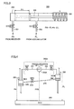
- Pressure accumulating unit 354 of pressure regulating unit 350 shown in Fig. 3 has a structure in which the pressure difference between receiver 230 and accumulator 250 is held mechanically and restored.
- Pressure accumulating unit 354 generally has a cylinder structure provided with a piston 355 in the cylindrical enclosure.
- An elastic body 356 such as a spring is connected to a rod-side end of piston 355, for example.
- the cylinder of pressure accumulating unit 354 has one side coupled to coolant passage 351 and the other side coupled to coolant passage 352 with the head part of piston 355 interposed therebetween.
- elastic body 356 is not limited to the spring as shown in Fig. 3 , but rubber, a compressible fluid (gas or liquid), or the like may be used.
- shut-off valves SV1 to SV4 in Fig. 2 are closed and furthermore, shut-off valves SV5 and SV6 are opened, the coolant from receiver 230 and accumulator 250 is supplied into the cylinder of pressure accumulating unit 354. On this occasion, piston 355 is moved in accordance with the pressure difference between pressure PH of the coolant from receiver 230 and pressure PL of the coolant from accumulator 250.
- piston 355 is moved by a distance ⁇ L from the state indicated by the broken line to the state indicated by the solid line in accordance with a pressure difference PH-PL.
- pressure accumulating unit 354 may be provided with a stopper (not shown) for fixing piston 355 with the pressure accumulated therein.
- shut-off valves SV5 and SV6 are opened after pressure PH of receiver 230 and pressure PL of accumulator 250 reach a similar level (PH ⁇ PL) by moving the coolant liquid from accumulator 250 to receiver 230, the force accumulated in elastic body 356 is released. Then, piston 355 is moved to compress the coolant in receiver 230, so that the pressure in receiver 230 is increased. Accordingly, the pressure difference before the coolant transfer can be restored.
- Pressure regulating unit 350 in Fig. 3 shows an example where the pressure difference is mechanically stored in elastic body 356 and restored therefrom.
- Fig. 4 illustrates another example of storing and restoring the pressure difference.
- a pressure regulating unit 350A includes a pump 354A instead of pressure accumulating unit 354.
- Pump 354A is controlled by a control signal PRS from ECU 300 to cause the gas-phase coolant in accumulator 250 to flow into receiver 230, thereby increasing the pressure in receiver 230.
- shut-off valves SV1 to SV4 in Fig. 2 are closed first, and pressure PH of receiver 230 and pressure PL of accumulator 250 in that state are detected by pressure sensors 280 and 285, respectively.
- ECU 300 calculates the pressure difference from the detected pressures for storage as a reference pressure difference.
- shut-off valves SV5, SV6 and switch valve 270 are opened with pump 350A stopped. Accordingly, the gas-phase coolant in receiver 230 is moved to accumulator 250 through coolant passages 351 and 352, while the coolant liquid in accumulator 250 is moved to receiver 230 through coolant passage 275.
- switch valve 270 is closed. Thereafter, by driving pump 354A, the coolant in receiver 230 is pressurized such that the pressure difference between receiver 230 and accumulator 250 approaches the pressure difference stored before the coolant transfer.
- the pressure accumulating unit may be increased in size, resulting in size increase of the pressure regulating unit as a whole.
- the driving force of the pump becomes necessary in order to restore the pressure difference, although the pressure regulating unit can be relatively reduced in size. It should be noted that, since the operation is conducted with shut-off valves SV1 to SV4 closed, a compressor smaller than compressor 210 can be used, so that a driving force can be made lower than when using compressor 210.
- the configuration of the pressure regulating unit is not limited to the above-described examples of Figs. 3 and 4 as long as it is configured to be capable of storing and restoring the pressure difference. Selection can be made appropriately as to which configuration is adopted for the pressure regulating unit, in consideration of the capacity of the receiver, that of the accumulator, the size of the whole device, and the like.
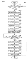
- Fig. 5 is a flowchart for describing coolant transfer control executed by ECU 300 in the first embodiment. Each step in the flowchart shown in Fig. 5 is achieved by a program previously stored in ECU 300 being revoked from a main routine and executed in a predetermined cycle or in response to satisfaction of predetermined conditions. Alternatively, processing of some steps can also be achieved by building dedicated hardware (an electronic circuit). It is to be noted that the flowchart of Fig. 5 illustrates an example in the case of pressure regulating unit 350 shown in Fig. 3 is used.
- step (hereinafter, step will be abbreviated to S) 100 ECU 300 determines whether or not level height HGT detected by level sensor 286 is higher than a predetermined threshold value Hth.
- ECU 300 Since it is not necessary to move the coolant liquid in accumulator 250 to receiver 230 when level height HGT is less than or equal to threshold value Hth (NO in S100), ECU 300 terminates the process skipping subsequent processing.
- level height HGT is higher than threshold value Hth (YES in S100)
- Hth threshold value
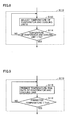
- step S110 includes step S111.
- ECU 300 determines whether or not vehicle 100 is at a stop. Since motor generator 130 is in the stopped state when vehicle 100 is at a stop, there is little current flowing into the circuit. Therefore, devices such as power storage device 110 and PCU 120 less rise in temperature, a temporary stop of the cooling operation by cooling device 200 for moving the temperature coolant liquid is less likely to affect the temperature rise of the devices.
- step S110 includes step S112.
- ECU 300 determines whether or not the temperature of each of the evaporator and cooling units 241, 242 is lower than a predetermined reference temperature Tth.
- Tth a predetermined reference temperature
- step S110 includes steps S113 and S114.
- ECU 300 controls expansion valve 260 and a decompression valve (not shown) provided for coolant passage 295 to adjust the temperature of evaporator 240 and cooling units 241, 242 to be lowered.
- Tth reference temperature
- the process is returned to S113, and adjustment is continued until the temperature of evaporator 240 and cooling units 241, 242 becomes lower than reference temperature Tth.
- Tth reference temperature of evaporator 240 and cooling units 241, 242 becomes lower than reference temperature Tth (YES in S114)
- the process is advanced to subsequent S120.
- a temporary stop of the cooling operation by cooling device 200 can be made at an early stage.
- step S110 includes steps S115 and S116.
- ECU 300 predicts the temperature rise rate of evaporator 240 and cooling units 241, 242 using the outside air temperature, the temperature of condenser 220 cooled by wind given by running of the vehicle, and the like, based on a map or the like previously obtained by experiment or the like. Then, it is determined in S116 whether or not the predicted temperature of evaporator 240 and cooling units 241, 242 predicted by means of this temperature rise rate is lower than reference temperature Tth.
- ECU 300 causes shut-off valves SV1 to SV4 to be closed to interrupt the flow of the coolant into/out of receiver 230 and accumulator 250.
- ECU 300 causes shut-off valves SV5 and SV6 to be opened to bring receiver 230 and pressure accumulating unit 354 into the communicating state and bring accumulator 250 and pressure accumulating unit 354 into the communicating state. Accordingly, as described with reference to Fig. 3 , the pressure difference between receiver 230 and accumulator 250 before the coolant liquid movement is accumulated in pressure accumulating unit 354 (S150).
- ECU 300 in S160 causes the pressure difference to be held by causing shut-off valves SV5 and SV6 to be closed.
- ECU 300 causes switch valve 270 to be opened to move the coolant liquid from accumulator 250 to receiver 230.
- the coolant liquid may not flow from accumulator 250 into receiver 230 as it is even if switch valve 270 is opened.
- a bypass route (coolant passage 353 and a shut-off valve SV7) as indicated by broken lines in Fig. 2 may be provided, and shut-off valve SV7 may be opened. Accordingly, the gas-phase coolant in receiver 230 can be moved to accumulator 250, and the coolant liquid can be caused to flow from accumulator 250 to receiver 230.
- ECU 300 determines whether or not the movement of the coolant liquid from accumulator 250 to receiver 230 has been completed. This determination may be made based on whether or not a predetermined time passed, or may be made based on whether or not level height HGT detected by level sensor 286 has been lowered to a predetermined height or below, for example.
- ECU 300 causes shut-off valves SV5 and SV6 to be opened.
- Piston 355 ( Fig. 3 ) of pressure accumulating unit 354 thus returns to its original position, so that the coolant in receiver 230 is pressurized.
- the pressure difference between receiver 230 and accumulator 250 is thereby brought close to the pressure difference before the coolant liquid movement (S210).
- ECU 300 in S220 causes shut-off valves SV5 and SV6 to be closed, and in S230 causes shut-off valves SV1 to SV4 to be opened. Thereafter, ECU 300 causes compressor 210 to operate to resume the cooling operation according to necessity.
- the coolant liquid in the accumulator can be moved to the receiver without driving the compressor.
- the pressure difference between the receiver and the accumulator can be brought close to the pressure difference before the coolant movement by means of the pressure regulating unit. Accordingly, recovery of the pressure difference by the compressor is not required when the cooling operation is resumed. Thus, it becomes possible to further reduce the load on the compressor.
- the shut-off valves for the coolant passages coupled to the receiver and the accumulator, the total capacity of the route in which the coolant is included can be reduced in restoration of the pressure difference by the pressure regulating unit. Therefore, the pressure regulating unit can be reduced in size.
- Fig. 10 illustrates a configuration of a cooling device 200A according to the second embodiment.
- receiver 230 and accumulator 250 have an integral structure such that accumulator 250 is located above receiver 230.
- a switch valve 400 is provided for a partition wall which separates receiver 230 and accumulator 250. It is to be noted that, in Fig. 10 , description of elements overlapping those of Fig. 2 will not be repeated.
- Switch valve 400 is a check valve opened/closed in accordance with the pressure difference between the pressure of accumulator 250 (pressure of a gas-phase coolant + pressure of a liquid-phase coolant) and the pressure of a gas-phase coolant in receiver 230.
- An example of the configuration of switch valve 400 will be described below with reference to Figs. 11 and 12 .
- Fig. 11 illustrates the state where switch valve 400 is closed
- Fig. 12 illustrates the state where switch valve 400 is opened.
- switch valve 400 includes an outlet 410, a closure lid 420, and a spring 430.
- Outlet 410 is provided at a partition wall 405 which separates receiver 230 and accumulator 250.
- Outlet 410 is provided at a partition wall 405 which separates receiver 230 and accumulator 250.
- Spring 430 biases, to closure lid 420, a force in a direction in which closure lid 420 is pressed against outlet 410.
- pressure PH of the gas-phase coolant in receiver 230 becomes larger than pressure PL of the gas-phase coolant in accumulator 250.
- pressure PL of the gas-phase coolant in accumulator 250 When the sum of pressure PH of the gas-phase coolant in receiver 230 and a biasing force ⁇ of spring 430 is larger than the sum of pressure PL of the gas-phase coolant in accumulator 250 and a pressure PW caused by the self-weight of the liquid-phase coolant (PH+ ⁇ >PL+PW), closure lid 420 is pressed against outlet 410 to bring receiver 230 and accumulator 250 out of communication. The coolant liquid in accumulator 250 is thus kept in accumulator 250.
- closure lid 420 closes.
- the receiver and the accumulator can be reduced in size. Furthermore, with such a structure, the coolant liquid in the accumulator can be moved to the receiver in accordance with the pressure difference between the receiver and the accumulator, without execution of active control by the ECU.
- the configuration of the check valve is not limited to the configurations shown in Figs. 11 and 12 as long as the configuration enables communication only in one direction in accordance with a predetermined pressure difference.
- a configuration may be adopted in which a plate having elasticity such as a rubber plate, for example, is provided at the partition wall on the receiver side.
- biasing force ⁇ of spring 430 is in the direction in which closure lid 420 is pressed against outlet 410 .
- the direction of biasing force ⁇ of spring 430 may be varied depending on the configuration of the system. For example, in the case of bringing receiver 230 and accumulator 260 into the communicating state as soon as possible after compressor 220 is stopped, the biasing force of spring 430 may be set to a direction in which closure lid 420 opens.
- the switch valve according to the first embodiment may be a check valve, and in contrast, the switch valve according to the second embodiment may be a control valve that can be controlled by the ECU.
Landscapes
- Engineering & Computer Science (AREA)
- Physics & Mathematics (AREA)
- Thermal Sciences (AREA)
- Mechanical Engineering (AREA)
- General Engineering & Computer Science (AREA)
- General Chemical & Material Sciences (AREA)
- Electrochemistry (AREA)
- Chemical Kinetics & Catalysis (AREA)
- Chemical & Material Sciences (AREA)
- Manufacturing & Machinery (AREA)
- Life Sciences & Earth Sciences (AREA)
- Sustainable Development (AREA)
- Sustainable Energy (AREA)
- Air-Conditioning For Vehicles (AREA)
- Secondary Cells (AREA)
Abstract
Description
- The present invention relates to a cooling device and a vehicle equipped with the same, as well as a control method for a cooling device, and more particularly to a technique for improving efficiency of a cooling device cooling a heat source utilizing a vapor compression refrigeration cycle.
- In recent years, as one of countermeasures against environmental problems, attention has been paid to a hybrid vehicle, a fuel cell vehicle, an electric vehicle, and the like running with driving force of a motor. In such vehicles, electric devices such as a motor, a generator, an inverter, a converter, and a battery generate heat by transmission and reception of electric power. Therefore, these electric devices need to be cooled. Accordingly, there is a proposed technique for cooling a heat-generating body utilizing a vapor compression refrigeration cycle used as an air-conditioning apparatus for a vehicle.
- For example, Japanese Patent Laying-Open No.
2007-69733 - Japanese Patent Laying-Open No.
2005-82066 -
- PTD 1: Japanese Patent Laying-Open No.
2007-069733 - PTD 2: Japanese Patent Laying-Open No.
2005-082066 - PTD 3: Japanese Patent Laying-Open No.
2005-090862 - PTD 4: Japanese Patent Laying-Open No.
06-255351 - For a cooling device in which a vapor compression refrigeration cycle is utilized, there is a known structure having a receiver for separating a coolant condensed by a condenser into gas and liquid to store coolant liquid and an accumulator for removing a liquid-phase component of the coolant to be sucked into the compressor.
- In the vapor compression refrigeration cycle, the coolant is lowered in temperature by expanding and evaporating the coolant liquid stored in the receiver, and cooling is executed through use of the coolant. Therefore, in order to ensure cooling ability, it is desirable for the coolant liquid to be stored sufficiently in the receiver.
- On the other hand, the accumulator is provided for preventing a failure of the compressor due to sucking of the coolant liquid into the compressor. The accumulator separates and stores the liquid-phase component remaining in the coolant used for cooling, and supplies only a gas-phase component of the coolant to the compressor.
- The coolant liquid stored in the accumulator cannot be used for cooling as it is. That is, in the case of using the coolant liquid again for cooling, it is necessary to return the coolant liquid from the accumulator to the receiver. In a general vapor compression refrigeration cycle, a technique of moving the coolant liquid from the accumulator to the receiver by operating the compressor to provide the coolant liquid in the accumulator with a superheat degree for evaporation, and liquefying the coolant liquid again through a condenser is adopted.
- In this case, however, the compressor needs to be operated even when cooling is unnecessary. Therefore, a load on the compressor may be increased to reduce the overall efficiency of the vapor compression refrigeration cycle.
- The present invention was made to solve such a problem, and has an object to, in a cooling device in which a vapor compression refrigeration cycle having a receiver and an accumulator is utilized, reduce a load on a compressor at the time of moving a coolant liquid from the accumulator to the receiver, thereby improving cooling efficiency.
- A cooling device according to the present invention performs cooling through use of a coolant. The cooling device includes a compressor configured to compress the coolant, first and second heat exchangers, first and second gas-liquid separating units, a decompressor, a switch valve, and a pressure regulating unit. The first heat exchanger is configured to perform heat exchange between the coolant having been compressed and outside air. The first gas-liquid separating unit is configured to separate the coolant having been subjected to the heat exchange by the first heat exchanger into gas and liquid. The decompressor is configured to decompress the coolant from the first gas-liquid separating unit. The second heat exchanger is configured to perform heat exchange between the coolant having been decompressed and air-conditioning air. The second gas-liquid separating unit is configured to separate the coolant having been subjected to the heat exchange by the second heat exchanger into gas and liquid, and supply the coolant to the compressor. The switch valve is configured to switch the first gas-liquid separating unit and the second gas-liquid separating unit into a communicating state to perform coolant transfer of a liquid-phase component from the second gas-liquid separating unit to the first gas-liquid separating unit. The pressure regulating unit is coupled to the first gas-liquid separating unit and the second gas-liquid separating unit and configured to adjust a pressure difference between the first gas-liquid separating unit and the second gas-liquid separating unit.
- Preferably, the cooling device further includes a control device. The control device controls the pressure regulating unit after the coolant transfer is terminated such that the pressure difference between the first gas-liquid separating unit and the second gas-liquid separating unit approaches a reference pressure difference which is a pressure difference before performing the coolant transfer.
- Preferably, the control device causes the pressure regulating unit to hold the reference pressure difference before starting the coolant transfer. The control device controls the pressure regulating unit after the coolant transfer is terminated such that the pressure difference between the first gas-liquid separating unit and the second gas-liquid separating unit approaches the reference pressure difference having been held.
- Preferably, the cooling device further includes first to fourth valves. The first valve is configured to interrupt flow of the coolant from the first heat exchanger into the first gas-liquid separating unit. The second valve is configured to interrupt flow of the coolant from the first gas-liquid separating unit into the decompressor. The third valve is configured to interrupt flow of the coolant from the second heat exchanger into the second gas-liquid separating unit. The fourth valve is configured to interrupt flow of the coolant from the second gas-liquid separating unit into the compressor. The control device causes the first, second, third, and fourth valves to be closed before starting the coolant transfer. The control device causes the first, second, third, and fourth valves to be opened after the coolant transfer is terminated.
- Preferably, the pressure regulating unit includes a pressure accumulating unit, a fifth valve configured to switch the first gas-liquid separating unit and the pressure accumulating unit between communication and out-of-communication, and a sixth valve configured to switch the second gas-liquid separating unit and the pressure accumulating unit between communication and out-of-communication. The control device causes the fifth valve and the sixth valve to be opened before starting the coolant transfer, and causes the pressure accumulating unit to hold a resultant pressure difference in the pressure accumulating unit as the reference pressure difference by causing the fifth valve and the sixth valve to be closed. The control device causes the fifth valve and the sixth valve to be opened after the coolant transfer is terminated to make the pressure difference between the first gas-liquid separating unit and the second gas-liquid separating unit approach the reference pressure difference.
- Preferably, the pressure accumulating unit has an elastic body. The pressure accumulating unit holds the reference pressure difference with an elastic force of the elastic body.
- Preferably, the control device causes the coolant transfer to be started when the compressor is at a stop.
- Preferably, the control device causes the coolant transfer to be started when the second heat exchanger has a temperature less than or equal to a reference temperature.
- Preferably, the control device causes the coolant transfer to be started after adjusting the second heat exchanger to have a temperature less than or equal to a reference temperature.
- Preferably, the control device predicts temperature rise of the second heat exchanger based on an operating state of the cooling device, and causes the coolant transfer to be started when a predicted temperature is less than or equal to a reference temperature.
- Preferably, the switch valve is opened when the pressure difference is smaller than a threshold value.
- Preferably, the cooling device further includes a cooling unit connected in parallel with the second heat exchanger and configured to cool a heat source with the coolant.
- Preferably, the second gas-liquid separating unit is arranged at a position relatively higher than the first gas-liquid separating unit.
- Preferably, the first gas-liquid separating unit and the second gas-liquid separating unit are formed integrally such that the second gas-liquid separating unit is located above the first gas-liquid separating unit. The switch valve is provided at a partition wall between the first gas-liquid separating unit and the second gas-liquid separating unit.
- Preferably, the switch valve is a check valve which is opened when a pressure on the side of the second gas-liquid separating unit, rather than the switch valve, becomes higher than the pressure on the side of the first gas-liquid separating unit by a prescribed value or more.
- A vehicle according to the present invention is capable of running with electric power from a power storage device. The vehicle includes a rotating electric machine, a driving device configured to convert electric power from the power storage device to drive the rotating electric machine, the above-described cooling device, and a cooling unit configured to cool at least one of the power storage device and the driving device through use of the cooling device.
- Preferably, the vehicle air-conditions a cabin with the cooling device.
- A vehicle according to the present invention is a control method for a cooling device configured to perform cooling through use of a coolant. The cooling device includes a compressor configured to compress the coolant, first and second heat exchangers, first and second gas-liquid separating units, a decompressor, a switch valve, and a pressure regulating unit. The first heat exchanger is configured to perform heat exchange between the coolant having been compressed and outside air. The first gas-liquid separating unit is configured to separate the coolant having been subjected to the heat exchange by the first heat exchanger into gas and liquid. The decompressor is configured to decompress the coolant from the first gas-liquid separating unit. The second heat exchanger is configured to perform heat exchange between the coolant having been decompressed and air-conditioning air. The second gas-liquid separating unit is configured to separate the coolant having been subjected to the heat exchange by the second heat exchanger into gas and liquid, and supply the coolant to the compressor. The switch valve is configured to switch the first gas-liquid separating unit and the second gas-liquid separating unit into a communicating state to perform coolant transfer of a liquid-phase component from the second gas-liquid separating unit to the first gas-liquid separating unit. The pressure regulating unit is coupled to the first gas-liquid separating unit and the second gas-liquid separating unit and configured to adjust a pressure difference between the first gas-liquid separating unit and the second gas-liquid separating unit. The control method includes the steps of detecting the pressure difference between the first gas-liquid separating unit and the second gas-liquid separating unit, holding the pressure difference between the first gas-liquid separating unit and the second gas-liquid separating unit before starting the coolant transfer as a reference pressure difference, performing the coolant transfer, and controlling the pressure regulating unit after the coolant transfer is terminated such that the pressure difference between the first gas-liquid separating unit and the second gas-liquid separating unit approaches the reference pressure difference having been stored.
- According to the present invention, in a cooling device in which a vapor compression refrigeration cycle having a receiver and an accumulator is utilized, a load on a compressor at the time of moving a coolant liquid from the accumulator to the receiver can be reduced to improve cooling efficiency.
-
-
Fig. 1 is an overall block diagram of a vehicle equipped with a cooling device in which a vapor compression refrigeration cycle according to the present embodiment is utilized. -
Fig. 2 is a block diagram for describing a configuration of the cooling device inFig. 1 in a first embodiment. -
Fig. 3 illustrates a first example of a pressure regulating unit inFig. 2 . -
Fig. 4 illustrates a second example of the pressure regulating unit inFig. 2 . -
Fig. 5 is a flowchart for describing coolant transfer control executed by ECU in the first embodiment. -
Fig. 6 illustrates a first example of step S110 inFig. 5 . -
Fig. 7 illustrates a second example of step S110 inFig. 5 . -
Fig. 8 illustrates a third example of step S110 inFig. 5 . -
Fig. 9 illustrates a fourth example of step S110 inFig. 5 . -
Fig. 10 illustrates a configuration of a cooling device according to a second embodiment. -
Fig. 11 is a first diagram for describing an operation of a switch valve in the cooling device inFig. 10 . -
Fig. 12 is a second diagram for describing an operation of the switch valve in the cooling device inFig. 10 . - Hereinafter, embodiments of the present invention will be described in detail with reference to the drawings. It is noted that, in the drawings, the same or corresponding portions have the same reference characters allotted, and detailed description thereof will not be repeated.
-
Fig. 1 is an overall block diagram of avehicle 100 equipped with acooling device 200 in which a vapor compression refrigeration cycle is utilized according to the present embodiment. In the present embodiment, although the case where coolingdevice 200 is used as an air-conditioner (A/C) for vehicle will be described by way of example, the application ofcooling device 200 is not limited thereto.Cooling device 200 is also applicable to, for example, a domestic air-conditioner, a cooling device for industrial equipment, or the like. -
Vehicle 100 is a type of vehicle that runs while obtaining running driving force by means of electric power from apower storage device 110. Although the case wherevehicle 100 is an electric vehicle will be described with reference toFig. 1 by way of example,vehicle 100 may be a hybrid vehicle having an internal combustion engine or a fuel-cell vehicle equipped with fuel cells. - In addition to
power storage device 110 andcooling device 200,vehicle 100 includes a system main relay (SMR) 115, a PCU (Power Control Unit) 120 as a driving device, amotor generator 130, adriving wheel 140, and an ECU (Electronic Control Unit) 300 as a control device.PCU 120 includes aconverter 121 and aninverter 125. -
Power storage device 110 is an electric power storage component configured to be rechargeable and dischargeable.Power storage device 110 is configured to include, for example, a secondary battery such as a lithium ion battery, a nickel-metal hydride battery or a lead acid battery, or a power storage element such as an electric double layer capacitor. -
Power storage device 110 is connected toPCU 120 via electric power lines PL1 and NL1.Power storage device 110 supplies electric power for generating driving force ofvehicle 100, toPCU 120.Power storage device 110 also stores electric power generated bymotor generator 130. The output ofpower storage device 110 is approximately 200V, for example. -
Power storage device 110 includes a voltage sensor and a current sensor, neither shown, and outputs a voltage VB and a current IB ofpower storage device 110, detected by these sensors, toECU 300. -
SMR 115 includes a relay connected across a positive terminal ofpower storage device 110 and electric power line PL1, as well as a relay connected across a negative terminal ofpower storage device 110 and electric power line NL1. Based on a control signal SE1 fromECU 300,SMR 115 switches between supply and interruption of electric power betweenpower storage device 110 andPCU 120. - Based on a control signal PWC from
ECU 300,converter 121 boosts electric power frompower storage device 110 and steps down electric power frominverter 125. -
Inverter 125 is connected toconverter 121 with electric power lines PL2 and NL1.Inverter 125 is controlled based on a control signal PWI fromECU 300.Inverter 125 converts DC power supplied fromconverter 121 into AC power to drivemotor generator 130. -
Motor generator 130 is an AC rotating electric machine, and is, for example, a permanent magnet-type synchronous motor including a rotor with a permanent magnet embedded therein. Furthermore, in the case of regenerative operation,motor generator 130 can generate electric power using rotary force from drivingwheel 140.Power storage device 110 is charged with electric power generated bymotor generator 130. -
Cooling device 200 is supplied with electric power from electric power lines PL1 and NL1.Cooling device 200 is controlled by a control signal CTL fromECU 300 to adjust the air temperature in a cabin ofvehicle 100. Coolant passages ofcooling device 200 are also arranged inpower storage device 110 as well as inconverter 121 andinverter 125 withinPCU 120. These coolant passages pass by the circumference of a housing accommodating each device or pass through the housing, or are joined to a coolant passage built in a main body of the device. Devices inpower storage device 110 andPCU 120 may generate heat by current conducting during running. Therefore, these devices can be cooled by flowing the coolant of coolingdevice 200 to the coolant passages of these devices as described above. As the coolant of coolingdevice 200, carbon dioxide, hydrocarbon such as propane or isobutane, ammonia, chlorofluorocarbon, or water can be used, for example. -
ECU 300 includes a CPU (Central Processing Unit), a memory device and an input/output buffer, none of which is shown inFig. 1 , and receives a signal from each sensor and outputs a control signal to each device, while exerting control ofvehicle 100 and each device. It is to be noted that these kinds of control is not limited to processing by software, but can be processed by dedicated hardware (an electronic circuit). -
ECU 300 receives detection values of voltage VB and current IB from the voltage sensor and the current sensor (neither shown) provided forpower storage device 110, and calculates the State of Charge SOC ofpower storage device 110. -
ECU 300 performs coolant transfer control for coolingdevice 200 as will be described below in detail. - It is to be noted that, although
Fig. 1 shows a configuration where one control device is provided asECU 300, it may be configured such that an individual control device is provided for each function or each device to be controlled. -
Fig. 2 is a block diagram for describing an example of a configuration ofcooling device 200 shown inFig. 1 according to the first embodiment.Cooling device 200 includes acompressor 210, acondenser 220, areceiver 230, anevaporator 240, anaccumulator 250, and anexpansion valve 260. It is to be noted thatcondenser 220 andevaporator 240 are examples of a "first heat exchanger" and a "second heat exchanger" of the present invention, respectively.Receiver 230 andaccumulator 250 are examples of a "first gas-liquid separating unit" and a "second gas-liquid separating unit" of the present invention, respectively.Expansion valve 260 is an example of a "decompressor" of the present invention. -
Compressor 210 is operated by motor generator 130 (Fig. 1 ), an engine or a dedicated motor mounted onvehicle 100 as a power source and adiabatically compresses the coolant gas to obtain superheated coolant gas.Compressor 210 is controlled by a control signal DRV fromECU 300.Compressor 210 takes in and compresses a gas-phase coolant flowing fromevaporator 240 throughaccumulator 250 during operation of the vapor compression refrigeration cycle, and then discharges a high-temperature and high-pressure gas-phase coolant tocoolant passage 297.Compressor 210 discharges the coolant tocoolant passage 297 to allow circulation of the coolant through the vapor compression refrigeration cycle. -
Condenser 220 allows superheated coolant gas compressed bycompressor 210 to radiate heat isobarically to an external medium to be condensed and to obtain coolant liquid. The high-pressure gas-phase coolant discharged fromcompressor 210 is condensed (liquefied) by radiating heat to a periphery ofcondenser 220 for cooling.Condenser 220 includes, for example, a tube through which the coolant flows, and a fin for performing heat exchange between the coolant flowing through the tube and air aroundcondenser 220. -
Condenser 220 performs heat exchange between cooling air and the coolant. The cooling air may be supplied tocondenser 220 by natural draft generated by vehicle running. Alternatively, the cooling air may be supplied tocondenser 220 by forced draft from an outside-air supplying fan such as a condenser fan or a radiator fan for cooling the engine (neither shown). The heat exchange with outside air incondenser 220 lowers the temperature of the coolant to liquefy the coolant. - The coolant cooled by
condenser 220 is supplied toreceiver 230 through acoolant passage 290. - The coolant flowing through
coolant passage 290 intoreceiver 230 is separated into a gas-phase coolant and a liquid-phase coolant withinreceiver 230. When all of the coolant does not evaporate incondenser 220 and the coolant flowing intoreceiver 230 is in a gas-liquid two-phase state,receiver 230 separates the coolant into coolant liquid in the liquid state and coolant vapor in the gaseous state, and temporarily stores the separated liquid and vapor therein. As for the coolant vapor obtained by gas-liquid separation, the coolant liquid accumulates on the lower side while the coolant vapor accumulates on the upper side withinreceiver 230. - In this manner, by accumulating a certain amount of coolant liquid in
receiver 230, the coolant liquid can be supplied appropriately also while load changes occur in terms of cooling. Therefore, the cooling performance can be stabilized also while load changes occur. - A
coolant passage 291 is coupled to the liquid-phase side (e.g., the bottom) ofreceiver 230. Therefore, only the coolant liquid is caused to flow fromreceiver 230 throughcoolant passage 291. In this manner,receiver 230 can reliably separate the gas-phase coolant and the liquid-phase coolant. -
Coolant passage 290 orreceiver 230 is provided with apressure sensor 280 for detecting the pressure of compressed coolant.Pressure sensor 280 outputs a detected pressure PH toECU 300. -
Expansion valve 260 allows the high-pressure liquid-phase coolant flowing throughcoolant passage 291 to be sprayed through a small pore for expansion to achieve a low-temperature, low-pressure mist-like coolant.Expansion valve 260 decompresses the coolant liquid condensed bycondenser 220 to produce moist vapor in a gas-liquid mixed state. It is to be noted that the decompressor for decompressing coolant liquid is not limited toexpansion valve 260 performing throttle expansion, but may be a capillary tube or a control valve whose opening degree can be controlled. -
Evaporator 240 performs heat exchange between the coolant and air-conditioning air, to regulate the temperature of the air-conditioning air.Evaporator 240 includes a tube through which the coolant flows, and a fin for heat exchange between the coolant flowing through the tube and the ambient air ofevaporator 240. The coolant in the state of moist vapor flows through the tube. When flowing through the tube, the coolant is evaporated by absorbing heat of the air within the vehicle cabin via the fin as latent heat of evaporation, and then turned into superheated vapor by sensible heat. By driving of the air-conditioning fan that is not shown, air-conditioning air is supplied toevaporator 240. The air-conditioning air may be outside air or may be air in the vehicle cabin. - During the cooling operation, in
evaporator 240, the coolant decompressed byexpansion valve 260 absorbs heat of evaporation, caused when the moist vapor of the coolant is evaporated to become coolant gas, from the air-conditioning air flowing into the vehicle cabin. The air-conditioning air with a temperature lowered due to absorption of heat by the coolant inevaporator 240 is returned again into the vehicle cabin. In this manner, the vehicle cabin is cooled. - In
evaporator 240, the air-conditioning air is cooled, while the coolant absorbs heat from its surroundings by heat transferred from the air-conditioning air and is then heated and evaporated. The coolant evaporated byevaporator 240 is caused to flow toaccumulator 250 through acoolant passage 295. - When all of the coolant does not evaporate in
evaporator 240 or coolingunits accumulator 250 is in a gas-liquid two-phase state,accumulator 250 separates the coolant into coolant liquid in the liquid state and coolant vapor in the gaseous state, and temporarily stores the separated liquid and vapor therein. - Within
accumulator 250, the coolant liquid accumulates on the lower side while the coolant vapor accumulates on the upper side. Acoolant passage 296 though which coolant vapor flows out ofaccumulator 250 is coupled to the ceiling portion ofaccumulator 250 and an inlet ofcompressor 210. Therefore, only the coolant vapor is caused to flow fromaccumulator 250 tocompressor 210 throughcoolant passage 296. In this manner,accumulator 250 can reliably separate the gas-phase coolant and the liquid-phase coolant. Accordingly, it becomes possible to prevent the liquid-phase coolant from flowing intocompressor 210 and to prevent a failure ofcompressor 210. -
Coolant passage 296 oraccumulator 250 is provided with apressure sensor 285 for detecting the pressure of the coolant flowing intocompressor 210.Pressure sensor 285 outputs a detected pressure PL toECU 300. -
Accumulator 250 is further provided with alevel sensor 286 for detecting the level height of the coolant liquid stored therein.Level sensor 286 outputs a detected level height HGT toECU 300. Any type of sensor can be used aslevel sensor 286. Examples oflevel sensor 286 include a float-type detector, a capacitance-type detector, a conduction detection-type detector, and the like, for example. -
Cooling device 200 further includes coolingunits evaporator 240 on the route of the coolant flowing fromexpansion valve 260 towardaccumulator 250. -
Coolant passages coolant passage 292.Coolant passage 293 passes throughcooling unit 241 to communicate withcoolant passage 295.Coolant passage 294 passes throughcooling unit 242 to communicate withcoolant passage 295. Part of the coolant decompressed byexpansion valve 260 and cooled passes throughcoolant passages coolant passage 295, and absorbs heat of devices included in coolingunits - Electric devices, such as
power storage device 110,converter 121,inverter 125 inFig. 1 , and the like, for example, are included in coolingunits Fig. 2 ,power storage device 110 is included incooling unit 241, andconverter 121 andinverter 125 ofPCU 120 are included incooling unit 242. It is to be noted that the devices included in coolingunits Fig. 1 ), an engine (not shown), and the like, for example. These devices which require cooling correspond to a "heat source" according to the invention of the present application. -
Coolant passages ECU 300, respectively. When brought into a closed state, shut-off valves SV1 to SV4 each interrupts the flow of coolant in each corresponding coolant passage. Accordingly, the coolant is prevented from flowing in/out ofreceiver 230 andaccumulator 250. It is to be noted that, in the case of a normal cooling operation, shut-off valves SV1 to SV4 are brought into an open position. - In this way, in the vapor compression refrigeration
cycle including receiver 230 andaccumulator 250 on the circulating passages of the coolant, the coolant liquid is stored inreceiver 230 andaccumulator 250. As described above, in order to produce a low-temperature, low-pressure mist-like coolant withexpansion valve 260, a liquid-phase coolant is supplied tocoolant passage 291 fromreceiver 230. Therefore, in order to ensure cooling ability, it is necessary to store the coolant liquid sufficiently inreceiver 230. - On the other hand, a gas-phase coolant is supplied to
compressor 210 fromaccumulator 250. Therefore, in order to return the coolant liquid stored inaccumulator 250 toreceiver 230, it is necessary to provide the coolant liquid with a necessary superheat degree for evaporation by operatingcompressor 210 to be condensed bycondenser 220. Then, motive power larger than in coolant transport in a normal cooling operation will be required forcompressor 210, which can degrade the overall efficiency of the cooling device. - Therefore, according to the first embodiment,
cooling device 200 is configured to further include acoolant passage 275 having aswitch valve 270 to bringreceiver 230 andaccumulator 250 into communication with each other.Coolant passage 275 has one end coupled to the liquid-phase side ofaccumulator 250, and the other end coupled to the gas-phase side ofreceiver 230. -
Switch valve 270 is controlled by a control signal SIGO fromECU 300 to switchreceiver 230 andaccumulator 250 between communication and out-of-communication. -
Accumulator 250 is arranged at a position where a junction betweenaccumulator 250 andcoolant passage 275 is higher than a junction betweenreceiver 230 andcoolant passage 275. With such an arrangement, whenswitch valve 270 is opened to bringreceiver 230 andaccumulator 250 into communication with each other, the coolant liquid can be moved toreceiver 230 utilizing the self-weight of the coolant liquid accumulated inaccumulator 250. Accordingly, the compression process bycompressor 210 and the condensation process bycondenser 220 become unnecessary. - As for the positional relationship between
receiver 230 andaccumulator 250, it is not essential to locateaccumulator 250 higher thanreceiver 230. For example, ifaccumulator 250 is arranged lower thanreceiver 230,coolant passage 275 may be further provided with a pump (not shown) for pumping up the coolant liquid inaccumulator 250 toreceiver 230. In this case, the coolant liquid inaccumulator 250 can be moved toreceiver 230 by openingswitch valve 270 and operating the pump. However, motive power for driving the pump will be required separately, although being less than motive power for operatingcompressor 210. Therefore, in terms of efficiency of the cooling device, it is more preferable to arrangeaccumulator 250 at a position higher thanreceiver 230 as shown inFig. 2 . - It is to be noted that, generally, since the gas-phase coolant is compressed by
compressor 210 whencompressor 210 is operated, pressure PH ofreceiver 230 which is on the discharge side ofcompressor 210 becomes higher than pressure PL ofaccumulator 250 which is at the flow-in side ofcompressor 210. Therefore, in the case where the difference between the pressure on thereceiver 230 side and the pressure on theaccumulator 250 side is greater than the pressure caused by the self-weight of the coolant liquid inaccumulator 250, the coolant liquid inaccumulator 250 may not flow intoreceiver 230 even whenswitch valve 270 is opened. - Therefore,
ECU 300 measures pressures PH and PL frompressure sensors switch valve 270. - In this way, in the first embodiment, it is possible to return the coolant liquid in
accumulator 250 toreceiver 230 as it is in the liquid phase by bringingreceiver 230 andaccumulator 250 into communication with each other. Since the load ofcompressor 210 can thereby be reduced, the overall efficiency ofcooling device 200 can be improved. - On the other hand, when
receiver 230 andaccumulator 250 are brought into communication with each other to move the coolant liquid, it is necessary to bring the pressure ofreceiver 230 and the pressure ofaccumulator 250 into a similar level as described above. Therefore, when the movement of the coolant liquid is completed and the cooling operation is resumed, it is necessary to operatecompressor 210 immediately after the resumption until a predetermined pressure difference occurs. Until the pressure difference occurs, however, sufficient cooling ability is not exhibited. Thus, the cooling efficiency may be degraded as a result. - Then, in addition to the above-described structure,
cooling device 200 of the first embodiment is further provided with apressure regulating unit 350 for restoring the pressure difference betweenreceiver 230 andaccumulator 250 after moving the coolant liquid fromaccumulator 250 toreceiver 230. -
Pressure regulating unit 350 is coupled to the gas-phase side ofreceiver 230 and the gas-phase side ofaccumulator 250 withcoolant passages Pressure regulating unit 350 includes pressure accumulating unit 154 as well as shut-off valves SV5 and SV6. - Shut-off valves SV5 and SV6 are provided for
coolant passages ECU 300, respectively. Shut-off valve SV5 interrupts the flow of coolant betweenpressure accumulating unit 354 andreceiver 230. Shut-off valve SV6 interrupts the flow of coolant betweenpressure accumulating unit 354 andaccumulator 250. It is to be noted that shut-off valves SV5 and SV6 are brought into the closed state during a normal cooling operation. - Next,
pressure regulating unit 350 will be described in detail with reference toFig. 3 .Pressure accumulating unit 354 ofpressure regulating unit 350 shown inFig. 3 has a structure in which the pressure difference betweenreceiver 230 andaccumulator 250 is held mechanically and restored.Pressure accumulating unit 354 generally has a cylinder structure provided with apiston 355 in the cylindrical enclosure. Anelastic body 356 such as a spring is connected to a rod-side end ofpiston 355, for example. The cylinder ofpressure accumulating unit 354 has one side coupled tocoolant passage 351 and the other side coupled tocoolant passage 352 with the head part ofpiston 355 interposed therebetween. It is to be noted thatelastic body 356 is not limited to the spring as shown inFig. 3 , but rubber, a compressible fluid (gas or liquid), or the like may be used. - When shut-off valves SV1 to SV4 in
Fig. 2 are closed and furthermore, shut-off valves SV5 and SV6 are opened, the coolant fromreceiver 230 andaccumulator 250 is supplied into the cylinder ofpressure accumulating unit 354. On this occasion,piston 355 is moved in accordance with the pressure difference between pressure PH of the coolant fromreceiver 230 and pressure PL of the coolant fromaccumulator 250. - For example, immediately after the stop of
compressor 210, when shut-off valves SV5 and SV6 are opened if PH>PL holds,piston 355 is moved by a distance ΔL from the state indicated by the broken line to the state indicated by the solid line in accordance with a pressure difference PH-PL. On this occasion, denoting the elastic modulus ofelastic body 356 as k, PH-PL=k•ΔL. - When shut-off valves SV5 and SV6 are closed again in this state, the state where a force corresponding to the pressure difference between
receiver 230 andaccumulator 250 is accumulated inelastic body 356 is maintained. That is, the pressure difference is held. It is to be noted thatpressure accumulating unit 354 may be provided with a stopper (not shown) for fixingpiston 355 with the pressure accumulated therein. - When shut-off valves SV5 and SV6 are opened after pressure PH of
receiver 230 and pressure PL ofaccumulator 250 reach a similar level (PH≃PL) by moving the coolant liquid fromaccumulator 250 toreceiver 230, the force accumulated inelastic body 356 is released. Then,piston 355 is moved to compress the coolant inreceiver 230, so that the pressure inreceiver 230 is increased. Accordingly, the pressure difference before the coolant transfer can be restored. -
Pressure regulating unit 350 inFig. 3 shows an example where the pressure difference is mechanically stored inelastic body 356 and restored therefrom.Fig. 4 illustrates another example of storing and restoring the pressure difference. - Referring to
Fig. 4 , in this example, apressure regulating unit 350A includes apump 354A instead ofpressure accumulating unit 354.Pump 354A is controlled by a control signal PRS fromECU 300 to cause the gas-phase coolant inaccumulator 250 to flow intoreceiver 230, thereby increasing the pressure inreceiver 230. - When moving the coolant liquid from
accumulator 250 toreceiver 230, shut-off valves SV1 to SV4 inFig. 2 are closed first, and pressure PH ofreceiver 230 and pressure PL ofaccumulator 250 in that state are detected bypressure sensors ECU 300 calculates the pressure difference from the detected pressures for storage as a reference pressure difference. - Then, shut-off valves SV5, SV6 and switch
valve 270 are opened withpump 350A stopped. Accordingly, the gas-phase coolant inreceiver 230 is moved toaccumulator 250 throughcoolant passages accumulator 250 is moved toreceiver 230 throughcoolant passage 275. - When the coolant transfer from
accumulator 250 toreceiver 230 is completed,switch valve 270 is closed. Thereafter, by drivingpump 354A, the coolant inreceiver 230 is pressurized such that the pressure difference betweenreceiver 230 andaccumulator 250 approaches the pressure difference stored before the coolant transfer. - When the pressure difference of the coolant reaches a predetermined value, pump 354A is stopped, and shut-off valves SV5 and SV6 are closed. The pressure difference between
receiver 230 andaccumulator 250 is thus restored to the reference pressure difference before the coolant transfer. - It is to be noted that, in such a structure as shown in
Fig. 3 where the pressure difference is mechanically stored and restored, an additional driving force becomes unnecessary. In order to restore the pressure difference, however, it is necessary to sufficiently increase the capacity in the cylinder. Therefore, depending on the receiver's capacity, the pressure accumulating unit may be increased in size, resulting in size increase of the pressure regulating unit as a whole. - On the other hand, with the configuration as shown in
Fig. 4 , the driving force of the pump becomes necessary in order to restore the pressure difference, although the pressure regulating unit can be relatively reduced in size. It should be noted that, since the operation is conducted with shut-off valves SV1 to SV4 closed, a compressor smaller thancompressor 210 can be used, so that a driving force can be made lower than when usingcompressor 210. - The configuration of the pressure regulating unit is not limited to the above-described examples of
Figs. 3 and 4 as long as it is configured to be capable of storing and restoring the pressure difference. Selection can be made appropriately as to which configuration is adopted for the pressure regulating unit, in consideration of the capacity of the receiver, that of the accumulator, the size of the whole device, and the like. -
Fig. 5 is a flowchart for describing coolant transfer control executed byECU 300 in the first embodiment. Each step in the flowchart shown inFig. 5 is achieved by a program previously stored inECU 300 being revoked from a main routine and executed in a predetermined cycle or in response to satisfaction of predetermined conditions. Alternatively, processing of some steps can also be achieved by building dedicated hardware (an electronic circuit). It is to be noted that the flowchart ofFig. 5 illustrates an example in the case ofpressure regulating unit 350 shown inFig. 3 is used. - Referring to
Figs. 2 and5 , in step (hereinafter, step will be abbreviated to S) 100,ECU 300 determines whether or not level height HGT detected bylevel sensor 286 is higher than a predetermined threshold value Hth. - Since it is not necessary to move the coolant liquid in
accumulator 250 toreceiver 230 when level height HGT is less than or equal to threshold value Hth (NO in S100),ECU 300 terminates the process skipping subsequent processing. - When level height HGT is higher than threshold value Hth (YES in S100), the process is advanced to S110, and
ECU 300 determines that the coolant liquid inaccumulator 250 needs to be moved toreceiver 230. Then, the process is advanced to S110, and it is determined whether or not the start condition for moving the coolant liquid fromaccumulator 250 toreceiver 230 is satisfied. - As the specific condition in S110, such a condition as shown in examples of
Figs. 6 to 9 can be employed, for example. - In the example of
Fig. 6 , step S110 includes step S111. In S111,ECU 300 determines whether or notvehicle 100 is at a stop. Sincemotor generator 130 is in the stopped state whenvehicle 100 is at a stop, there is little current flowing into the circuit. Therefore, devices such aspower storage device 110 andPCU 120 less rise in temperature, a temporary stop of the cooling operation by coolingdevice 200 for moving the temperature coolant liquid is less likely to affect the temperature rise of the devices. - When
vehicle 100 is not at a stop (NO in S111), the process is returned to S111, andECU 300 waits forvehicle 100 to be brought into the stopped state. On the other hand, whenvehicle 100 is at a stop (YES in S111), the process is advanced tosubsequent S 120. - In the example of
Fig. 7 , step S110 includes step S112. In S112,ECU 300 determines whether or not the temperature of each of the evaporator and coolingunits units device 200 is low. Thus, a temporary stop of the cooling operation by coolingdevice 200 for moving the coolant liquid is less likely to affect the temperature rise of the devices. - When the temperature of
evaporator 240 and coolingunits ECU 300 waits for the temperature ofevaporator 240 and coolingunits evaporator 240 and coolingunits - In the example of
Fig. 8 , step S110 includes steps S113 and S114. In S113,ECU 300 controlsexpansion valve 260 and a decompression valve (not shown) provided forcoolant passage 295 to adjust the temperature ofevaporator 240 and coolingunits evaporator 240 and coolingunits evaporator 240 and coolingunits evaporator 240 and coolingunits - In
Fig. 8 , by actively lowering the temperature ofevaporator 240 and coolingunits device 200 can be made at an early stage. - In the example of
Fig. 9 , step S110 includes steps S115 and S116. In S115,ECU 300 predicts the temperature rise rate ofevaporator 240 and coolingunits condenser 220 cooled by wind given by running of the vehicle, and the like, based on a map or the like previously obtained by experiment or the like. Then, it is determined in S116 whether or not the predicted temperature ofevaporator 240 and coolingunits - When the predicted temperature of
evaporator 240 and coolingunits ECU 300 waits for the predicted temperature ofevaporator 240 and coolingunits evaporator 240 and coolingunits - It is to be noted that, in the case of the start conditions shown in
Figs. 8 and 9 , it is not necessarily required to bring the vehicle into the stopped state. When the temperature rise of the devices can be suppressed low, the movement of the coolant liquid can be started even while the vehicle is running. - Referring again to
Fig. 5 , when the start condition for moving the coolant liquid in S110 is met, the process is advanced to S120, andECU 300 stopscompressor 210. - Then, in S130,
ECU 300 causes shut-off valves SV1 to SV4 to be closed to interrupt the flow of the coolant into/out ofreceiver 230 andaccumulator 250. - Then, in S140,
ECU 300 causes shut-off valves SV5 and SV6 to be opened to bringreceiver 230 andpressure accumulating unit 354 into the communicating state and bringaccumulator 250 andpressure accumulating unit 354 into the communicating state. Accordingly, as described with reference toFig. 3 , the pressure difference betweenreceiver 230 andaccumulator 250 before the coolant liquid movement is accumulated in pressure accumulating unit 354 (S150). - When the accumulation of the pressure difference in
pressure accumulating unit 354 is completed,ECU 300 in S160 causes the pressure difference to be held by causing shut-off valves SV5 and SV6 to be closed. - Then, in S170,
ECU 300 causes switchvalve 270 to be opened to move the coolant liquid fromaccumulator 250 toreceiver 230. - It is to be noted that, when the pressure on the
receiver 230 side is still higher than the pressure on theaccumulator 250 side even after causing the pressure difference to be held inpressure accumulating unit 354, the coolant liquid may not flow fromaccumulator 250 intoreceiver 230 as it is even ifswitch valve 270 is opened. In such a case, for example, a bypass route (coolant passage 353 and a shut-off valve SV7) as indicated by broken lines inFig. 2 may be provided, and shut-off valve SV7 may be opened. Accordingly, the gas-phase coolant inreceiver 230 can be moved toaccumulator 250, and the coolant liquid can be caused to flow fromaccumulator 250 toreceiver 230. - In S180,
ECU 300 determines whether or not the movement of the coolant liquid fromaccumulator 250 toreceiver 230 has been completed. This determination may be made based on whether or not a predetermined time passed, or may be made based on whether or not level height HGT detected bylevel sensor 286 has been lowered to a predetermined height or below, for example. - When the movement of the coolant liquid has not been completed (NO in S180), the process is advanced to S180, and
ECU 300 waits for completion of the movement of the coolant liquid. - On the other hand, when the movement of the coolant liquid has been completed (YES in S180), the process is advanced to S190, and
ECU 300 causes switchvalve 270 to be closed. On this occasion, when the above-described bypass circuit is provided,ECU 300 also causes shut-off valve SV7 to be closed. - Thereafter, in S200,
ECU 300 causes shut-off valves SV5 and SV6 to be opened. Piston 355 (Fig. 3 ) ofpressure accumulating unit 354 thus returns to its original position, so that the coolant inreceiver 230 is pressurized. The pressure difference betweenreceiver 230 andaccumulator 250 is thereby brought close to the pressure difference before the coolant liquid movement (S210). - Then,
ECU 300 in S220 causes shut-off valves SV5 and SV6 to be closed, and in S230 causes shut-off valves SV1 to SV4 to be opened. Thereafter,ECU 300 causescompressor 210 to operate to resume the cooling operation according to necessity. - By exerting control in accordance with the processing as described above, in the cooling device in which the vapor compression refrigeration cycle having the receiver and the accumulator is used, the coolant liquid in the accumulator can be moved to the receiver without driving the compressor. After the movement of the coolant liquid from the accumulator to the receiver, the pressure difference between the receiver and the accumulator can be brought close to the pressure difference before the coolant movement by means of the pressure regulating unit. Accordingly, recovery of the pressure difference by the compressor is not required when the cooling operation is resumed. Thus, it becomes possible to further reduce the load on the compressor. Furthermore, by providing the shut-off valves for the coolant passages coupled to the receiver and the accumulator, the total capacity of the route in which the coolant is included can be reduced in restoration of the pressure difference by the pressure regulating unit. Therefore, the pressure regulating unit can be reduced in size.
- In the first embodiment, the configuration where the receiver and the accumulator are brought into communication with each other via the coolant passages has been described.
- In a second embodiment, the configuration where the accumulator and the receiver have an integral structure such that the accumulator is located above the receiver will be described.
-
Fig. 10 illustrates a configuration of acooling device 200A according to the second embodiment. Incooling device 200A,receiver 230 andaccumulator 250 have an integral structure such thataccumulator 250 is located abovereceiver 230. Aswitch valve 400 is provided for a partition wall which separatesreceiver 230 andaccumulator 250. It is to be noted that, inFig. 10 , description of elements overlapping those ofFig. 2 will not be repeated. -
Switch valve 400 is a check valve opened/closed in accordance with the pressure difference between the pressure of accumulator 250 (pressure of a gas-phase coolant + pressure of a liquid-phase coolant) and the pressure of a gas-phase coolant inreceiver 230. An example of the configuration ofswitch valve 400 will be described below with reference toFigs. 11 and12 . -
Fig. 11 illustrates the state whereswitch valve 400 is closed, andFig. 12 illustrates the state whereswitch valve 400 is opened. - Referring to
Figs. 10 and11 ,switch valve 400 includes anoutlet 410, aclosure lid 420, and aspring 430. -
Outlet 410 is provided at apartition wall 405 which separatesreceiver 230 andaccumulator 250. Whenclosure lid 420 is in the open state,receiver 230 andaccumulator 250 are brought into the communicating state.Spring 430 biases, toclosure lid 420, a force in a direction in whichclosure lid 420 is pressed againstoutlet 410. - When
compressor 210 is operating, pressure PH of the gas-phase coolant inreceiver 230 becomes larger than pressure PL of the gas-phase coolant inaccumulator 250. When the sum of pressure PH of the gas-phase coolant inreceiver 230 and a biasing force α ofspring 430 is larger than the sum of pressure PL of the gas-phase coolant inaccumulator 250 and a pressure PW caused by the self-weight of the liquid-phase coolant (PH+α>PL+PW),closure lid 420 is pressed againstoutlet 410 to bringreceiver 230 andaccumulator 250 out of communication. The coolant liquid inaccumulator 250 is thus kept inaccumulator 250. - When
compressor 210 is stopped, the pressure difference between pressure PH and pressure PL decreases gradually with time. Then, as shown inFig. 12 , when the sum of pressure PH of the gas-phase coolant inreceiver 230 and biasing force α ofspring 430 becomes smaller than the sum of pressure PL of the gas-phase coolant inaccumulator 250 and pressure PW caused by the self-weight of the liquid-phase coolant (PH+α<PL+PW),closure lid 420 opens. This causesreceiver 230 andaccumulator 250 to communicate with each other, so that the coolant liquid inaccumulator 250 is moved toreceiver 230 through a route indicated by an arrow AR1. - Thereafter, when the coolant liquid is moved to increase the pressure on the
receiver 230 side (PH+α>PL+PW),closure lid 420 closes. - In this manner, by providing the integral structure of the receiver and the accumulator and providing the partition wall therebetween with the check valve that allows the flow in the direction from the accumulator to the receiver, the receiver and the accumulator can be reduced in size. Furthermore, with such a structure, the coolant liquid in the accumulator can be moved to the receiver in accordance with the pressure difference between the receiver and the accumulator, without execution of active control by the ECU.
- By making an adjustment to attain the pressure difference before the movement of the coolant liquid by the pressure regulating unit after the movement of the coolant liquid from the receiver to the accumulator, a pressurizing operation by the compressor is not required at the time of resumption of a cooling operation, which can improve cooling efficiency.
- It is to be noted that the configuration of the check valve is not limited to the configurations shown in
Figs. 11 and12 as long as the configuration enables communication only in one direction in accordance with a predetermined pressure difference. As another configuration of the check valve, a configuration may be adopted in which a plate having elasticity such as a rubber plate, for example, is provided at the partition wall on the receiver side. - In the description of
Figs. 11 and12 , the case where biasing force α ofspring 430 is in the direction in whichclosure lid 420 is pressed againstoutlet 410 has been described by way of example. The direction of biasing force α ofspring 430 may be varied depending on the configuration of the system. For example, in the case of bringingreceiver 230 andaccumulator 260 into the communicating state as soon as possible aftercompressor 220 is stopped, the biasing force ofspring 430 may be set to a direction in whichclosure lid 420 opens. - The switch valve according to the first embodiment may be a check valve, and in contrast, the switch valve according to the second embodiment may be a control valve that can be controlled by the ECU.
- It should be understood that the embodiments disclosed herein are illustrative and non-restrictive in every respect. The scope of the present invention is defined by the claims not by the description above, and is intended to include any modification within the meaning and scope equivalent to the terms of the claims.
- 100 vehicle; 110 power storage device; 120 PCU; 121 converter; 125 inverter; 130 motor generator; 140 driving wheel; 200, 200A cooling device; 210 compressor; 220 condenser; 230 receiver; 240 evaporator; 241, 242 cooling unit; 250 accumulator; 260 expansion valve; 270, 400 switch valve; 275, 290-297, 351-353 coolant passage: 280, 285 pressure sensor; 286 level sensor; 300 ECU; 350, 350A pressure regulating unit; 354 pressure accumulating unit; 354A pump; 355 piston; 356 elastic body; 405 partition wall; 410 outlet; 420 closure lid; 430 spring; PL1, PL2, NL1 electric power line; SV1-SV7 shut-off valve.
Claims (18)
- A cooling device configured to perform cooling through use of a coolant, comprising:a compressor (210) configured to compress the coolant;a first heat exchanger (220) configured to perform heat exchange between the coolant having been compressed and outside air;a first gas-liquid separating unit (230) configured to separate the coolant having been subjected to the heat exchange by the first heat exchanger into gas and liquid;a decompressor (260) configured to decompress the coolant from the first gas-liquid separating unit;a second heat exchanger (240) configured to perform heat exchange between the coolant having been decompressed and air-conditioning air;a second gas-liquid separating unit (250) configured to separate the coolant having been subjected to the heat exchange by the second heat exchanger into gas and liquid, and supply the coolant to the compressor;a switch valve (270, 400) configured to switch the first gas-liquid separating unit and the second gas-liquid separating unit into a communicating state to perform coolant transfer of a liquid-phase component from the second gas-liquid separating unit to the first gas-liquid separating unit; anda pressure regulating unit (350, 350A) coupled to the first gas-liquid separating unit and the second gas-liquid separating unit and configured to adjust a pressure difference between the first gas-liquid separating unit and the second gas-liquid separating unit.
- The cooling device according to claim 1, further comprising a control device (300), wherein
the control device controls the pressure regulating unit after the coolant transfer is terminated such that the pressure difference between the first gas-liquid separating unit and the second gas-liquid separating unit approaches a reference pressure difference which is a pressure difference before performing the coolant transfer. - The cooling device according to claim 2, wherein
the control device causes the pressure regulating unit to hold the reference pressure difference before starting the coolant transfer, and
the control device controls the pressure regulating unit after the coolant transfer is terminated such that the pressure difference between the first gas-liquid separating unit and the second gas-liquid separating unit approaches the reference pressure difference having been held. - The cooling device according to claim 2, further comprising:a first valve (SV1) configured to interrupt flow of the coolant from the first heat exchanger into the first gas-liquid separating unit;a second valve (SV2) configured to interrupt flow of the coolant from the first gas-liquid separating unit into the decompressor;a third valve (SV3) configured to interrupt flow of the coolant from the second heat exchanger into the second gas-liquid separating unit; anda fourth valve (SV4) configured to interrupt flow of the coolant from the second gas-liquid separating unit into the compressor, whereinthe control device causes the first, second, third, and fourth valves to be closed before starting the coolant transfer, andthe control device causes the first, second, third, and fourth valves to be opened after the coolant transfer is terminated.
- The cooling device according to claim 4, wherein
the pressure regulating unit includes
a pressure accumulating unit (354),
a fifth valve (SV5) configured to switch the first gas-liquid separating unit and the pressure accumulating unit between communication and out-of-communication, and
a sixth valve (SV6) configured to switch the second gas-liquid separating unit and the pressure accumulating unit between communication and out-of-communication,
the control device causes the fifth valve and the sixth valve to be opened before starting the coolant transfer, and causes the pressure accumulating unit to hold a resultant pressure difference in the pressure accumulating unit as the reference pressure difference by causing the fifth valve and the sixth valve to be closed, and
the control device causes the fifth valve and the sixth valve to be opened after the coolant transfer is terminated to make the pressure difference between the first gas-liquid separating unit and the second gas-liquid separating unit approach the reference pressure difference. - The cooling device according to claim 5, wherein
the pressure accumulating unit has an elastic body (356), and
the pressure accumulating unit holds the reference pressure difference with an elastic force of the elastic body. - The cooling device according to claim 4, wherein the control device causes the coolant transfer to be started when the compressor is at a stop.
- The cooling device according to claim 4, wherein the control device causes the coolant transfer to be started when the second heat exchanger has a temperature less than or equal to a reference temperature.
- The cooling device according to claim 4, wherein the control device causes the coolant transfer to be started after adjusting the second heat exchanger to have a temperature less than or equal to a reference temperature.
- The cooling device according to claim 4, wherein the control device predicts temperature rise of the second heat exchanger based on an operating state of the cooling device, and causes the coolant transfer to be started when a predicted temperature is less than or equal to a reference temperature.
- The cooling device according to claim 2, wherein the switch valve is opened when the pressure difference is smaller than a threshold value.
- The cooling device according to claim 1, further comprising a cooling unit (241, 242) connected in parallel with the second heat exchanger and configured to cool a heat source (110, 120) with the coolant.
- The cooling device according to claim 1, wherein the second gas-liquid separating unit is arranged at a position relatively higher than the first gas-liquid separating unit.
- The cooling device according to claim 13, wherein
the first gas-liquid separating unit and the second gas-liquid separating unit are formed integrally such that the second gas-liquid separating unit is located above the first gas-liquid separating unit, and
the switch valve is provided at a partition wall (405) between the first gas-liquid separating unit and the second gas-liquid separating unit. - The cooling device according to claim 13 or 14, wherein the switch valve is a check valve which is opened when a pressure on the side of the second gas-liquid separating unit, rather than the switch valve, becomes higher than the pressure on the side of the first gas-liquid separating unit by a prescribed value or more.
- A vehicle capable of running with electric power from a power storage device (110), comprising:a rotating electric machine (130);a driving device (120) configured to convert electric power from the power storage device (110) to drive the rotating electric machine (130);the cooling device as defined in claim 1; anda cooling unit (241, 242) configured to cool at least one of the power storage device (110) and the driving device (120) through use of the cooling device.
- The vehicle according to claim 16, wherein the vehicle air-conditions a cabin with the cooling device.
- A control method for a cooling device configured to perform cooling through use of a coolant,
the cooling device (200) including
a compressor (210) configured to compress the coolant,
a first heat exchanger (220) configured to perform heat exchange between the coolant having been compressed and outside air,
a first gas-liquid separating unit (230) configured to separate the coolant having been subjected to the heat exchange by the first heat exchanger into gas and liquid,
a decompressor (260) configured to decompress the coolant from the first gas-liquid separating unit,
a second heat exchanger (240) configured to perform heat exchange between the coolant having been decompressed and air-conditioning air,
a second gas-liquid separating unit (250) configured to separate the coolant having been subjected to the heat exchange by the second heat exchanger into gas and liquid, and supply the coolant to the compressor,
a switch valve (270) configured to switch the first gas-liquid separating unit and the second gas-liquid separating unit into a communicating state to perform coolant transfer of a liquid-phase component from the second gas-liquid separating unit to the first gas-liquid separating unit, and
a pressure regulating unit (350, 350A) coupled to the first gas-liquid separating unit and the second gas-liquid separating unit and configured to adjust a pressure difference between the first gas-liquid separating unit and the second gas-liquid separating unit,
the control method comprising the steps of:detecting the pressure difference between the first gas-liquid separating unit and the second gas-liquid separating unit;holding the pressure difference between the first gas-liquid separating unit and the second gas-liquid separating unit before starting the coolant transfer as a reference pressure difference;performing the coolant transfer; andcontrolling the pressure regulating unit after the coolant transfer is terminated such that the pressure difference between the first gas-liquid separating unit and the second gas-liquid separating unit approaches the reference pressure difference having been stored.
Applications Claiming Priority (1)
| Application Number | Priority Date | Filing Date | Title |
|---|---|---|---|
| PCT/JP2012/054401 WO2013125005A1 (en) | 2012-02-23 | 2012-02-23 | Cooling device, vehicle provided with same, and control method for cooling device |
Publications (3)
| Publication Number | Publication Date |
|---|---|
| EP2818808A1 true EP2818808A1 (en) | 2014-12-31 |
| EP2818808A4 EP2818808A4 (en) | 2015-10-07 |
| EP2818808B1 EP2818808B1 (en) | 2016-12-21 |
Family
ID=49005226
Family Applications (1)
| Application Number | Title | Priority Date | Filing Date |
|---|---|---|---|
| EP12869207.6A Active EP2818808B1 (en) | 2012-02-23 | 2012-02-23 | Cooling device, vehicle provided with same, and control method for cooling device |
Country Status (5)
| Country | Link |
|---|---|
| US (1) | US9233594B2 (en) |
| EP (1) | EP2818808B1 (en) |
| JP (1) | JP5804177B2 (en) |
| CN (1) | CN104136865B (en) |
| WO (1) | WO2013125005A1 (en) |
Cited By (2)
| Publication number | Priority date | Publication date | Assignee | Title |
|---|---|---|---|---|
| EP3739279A1 (en) * | 2019-05-13 | 2020-11-18 | Heatcraft Refrigeration Products LLC | Cooling system with additional receiver |
| AU2016297673B2 (en) * | 2015-07-20 | 2022-03-31 | Cresstec Rac Ip Pty. Ltd. | A subsystem for a vapour-compression system, a vapour-compression system, and a method for a vapour-compression system |
Families Citing this family (19)
| Publication number | Priority date | Publication date | Assignee | Title |
|---|---|---|---|---|
| JP5798402B2 (en) * | 2011-08-01 | 2015-10-21 | トヨタ自動車株式会社 | Cooling system |
| DE102015107473A1 (en) * | 2015-05-12 | 2016-11-17 | Benteler Automobiltechnik Gmbh | Automotive heat exchanger system |
| US10290911B2 (en) * | 2015-05-18 | 2019-05-14 | Toyota Motor Engineering & Manufacturing North America, Inc. | Cooling loops and vehicles incorporating the same |
| US20170101437A1 (en) * | 2015-10-09 | 2017-04-13 | Hetero Drugs Ltd. | Process for purification of darbepoetin alfa |
| CN105751851B (en) * | 2016-02-19 | 2018-11-30 | 成都雅骏新能源汽车科技股份有限公司 | A kind of refrigerator car electric control system |
| US11839062B2 (en) | 2016-08-02 | 2023-12-05 | Munters Corporation | Active/passive cooling system |
| JP7027910B2 (en) * | 2018-01-25 | 2022-03-02 | トヨタ自動車株式会社 | Electric vehicle |
| DE102018113687B4 (en) * | 2018-06-08 | 2023-08-03 | Hanon Systems | Device and method for cooling battery cell modules |
| JP6849036B1 (en) * | 2019-09-30 | 2021-03-24 | ダイキン工業株式会社 | Heat source unit and refrigeration equipment |
| WO2021111605A1 (en) * | 2019-12-05 | 2021-06-10 | 三菱電機株式会社 | Refrigeration cycle device |
| US11407274B2 (en) * | 2020-03-12 | 2022-08-09 | Denso International America, Inc | Accumulator pressure drop regulation system for a heat pump |
| DE102020129539A1 (en) | 2020-11-10 | 2022-05-12 | Bayerische Motoren Werke Aktiengesellschaft | Air conditioning system and method for controlling such |
| EP4000991B1 (en) * | 2020-11-19 | 2024-08-14 | ABB E-mobility B.V. | Electric vehicle charging connector with external passive cooling |
| EP4060254A1 (en) | 2021-03-18 | 2022-09-21 | Danfoss A/S | A method for controlling a vapour compression system with a bypass valve |
| US11541719B1 (en) * | 2021-07-14 | 2023-01-03 | GM Global Technology Operations LLC | Active thermal management systems and control logic for heat exchanger storage of refrigerant |
| FR3125872A1 (en) * | 2021-07-28 | 2023-02-03 | Valeo Systemes Thermiques | Motor vehicle thermal conditioning system |
| EP4164011B1 (en) * | 2021-10-05 | 2024-04-24 | Volvo Truck Corporation | Heat transfer fluid system for a vehicle |
| CN114484952A (en) * | 2021-12-23 | 2022-05-13 | 矩阵数据科技(上海)有限公司 | Environment cabin-based electric vehicle refrigerant charge capacity calibration test method |
| CN115289727B (en) * | 2022-07-27 | 2025-01-28 | 苏州海派特热能设备有限公司 | Dynamic combined energy-saving dehumidification system |
Family Cites Families (16)
| Publication number | Priority date | Publication date | Assignee | Title |
|---|---|---|---|---|
| US4122688A (en) * | 1976-07-30 | 1978-10-31 | Hitachi, Ltd. | Refrigerating system |
| JP3000584B2 (en) | 1989-02-20 | 2000-01-17 | ダイキン工業株式会社 | Refrigeration equipment |
| US5189885A (en) * | 1991-11-08 | 1993-03-02 | H. A. Phillips & Co. | Recirculating refrigeration system |
| JPH06255351A (en) | 1993-03-02 | 1994-09-13 | Seiko Epson Corp | Electric vehicle cooling cycle |
| JP2000016070A (en) | 1998-07-03 | 2000-01-18 | Denso Corp | Air conditioner |
| US6311507B1 (en) * | 2000-10-19 | 2001-11-06 | Carter Burgess, Incorporated | Refrigeration system with minimum pre-set condensing pressure |
| JP2003028522A (en) * | 2001-07-16 | 2003-01-29 | Zexel Valeo Climate Control Corp | Refrigerating cycle |
| JP2004183982A (en) | 2002-12-03 | 2004-07-02 | Fujitsu General Ltd | Control device for air conditioner |
| JP2005082066A (en) | 2003-09-10 | 2005-03-31 | Toyota Motor Corp | Cooling system |
| JP2005090862A (en) | 2003-09-17 | 2005-04-07 | Toyota Motor Corp | Cooling system |
| JP2007069733A (en) | 2005-09-07 | 2007-03-22 | Valeo Thermal Systems Japan Corp | Heating element cooling system using air conditioner for vehicle |
| JP4335893B2 (en) * | 2006-08-18 | 2009-09-30 | 三星電子株式会社 | Air conditioner |
| JP2009156544A (en) | 2007-12-27 | 2009-07-16 | Calsonic Kansei Corp | Air conditioner and air-conditioning method |
| DE102008035216A1 (en) * | 2008-04-19 | 2009-10-22 | Daimler Ag | Cooling arrangement and method for cooling a temperature-sensitive aggregate of a motor vehicle |
| JP5495949B2 (en) * | 2010-05-27 | 2014-05-21 | 三菱電機株式会社 | Refrigeration equipment |
| WO2013125006A1 (en) | 2012-02-23 | 2013-08-29 | トヨタ自動車株式会社 | Cooling device and vehicle mounted with same, and method for controlling cooling device |
-
2012
- 2012-02-23 JP JP2014500814A patent/JP5804177B2/en active Active
- 2012-02-23 EP EP12869207.6A patent/EP2818808B1/en active Active
- 2012-02-23 US US14/379,648 patent/US9233594B2/en active Active
- 2012-02-23 WO PCT/JP2012/054401 patent/WO2013125005A1/en not_active Ceased
- 2012-02-23 CN CN201280070492.0A patent/CN104136865B/en active Active
Cited By (4)
| Publication number | Priority date | Publication date | Assignee | Title |
|---|---|---|---|---|
| AU2016297673B2 (en) * | 2015-07-20 | 2022-03-31 | Cresstec Rac Ip Pty. Ltd. | A subsystem for a vapour-compression system, a vapour-compression system, and a method for a vapour-compression system |
| EP3325899B1 (en) * | 2015-07-20 | 2022-07-06 | Cresstec RAC IP Pty. Ltd. | A subsystem for a vapour-compression system |
| EP3739279A1 (en) * | 2019-05-13 | 2020-11-18 | Heatcraft Refrigeration Products LLC | Cooling system with additional receiver |
| US11493247B2 (en) | 2019-05-13 | 2022-11-08 | Heatcraft Refrigeration Products Llc | Cooling system with additional receiver |
Also Published As
| Publication number | Publication date |
|---|---|
| JPWO2013125005A1 (en) | 2015-05-21 |
| CN104136865B (en) | 2016-03-16 |
| EP2818808B1 (en) | 2016-12-21 |
| CN104136865A (en) | 2014-11-05 |
| WO2013125005A1 (en) | 2013-08-29 |
| EP2818808A4 (en) | 2015-10-07 |
| JP5804177B2 (en) | 2015-11-04 |
| US9233594B2 (en) | 2016-01-12 |
| US20150013363A1 (en) | 2015-01-15 |
Similar Documents
| Publication | Publication Date | Title |
|---|---|---|
| EP2818808B1 (en) | Cooling device, vehicle provided with same, and control method for cooling device | |
| US20140326010A1 (en) | Cooling device | |
| EP2699432B1 (en) | Cooling apparatus | |
| EP2672200B1 (en) | Cooling device | |
| EP2781380B1 (en) | Device for cooling electrical apparatus | |
| JP5837369B2 (en) | Control device and control method for cooling device | |
| EP2781381B1 (en) | Device for cooling electrical apparatus | |
| US9631544B2 (en) | Cooling system and vehicle that includes cooling system | |
| EP2765368B1 (en) | Control method for cooling apparatus | |
| WO2013125006A1 (en) | Cooling device and vehicle mounted with same, and method for controlling cooling device | |
| EP2714442B1 (en) | Cooling system and vehicle | |
| JP2014121228A (en) | vehicle | |
| JP5692121B2 (en) | COOLING DEVICE, VEHICLE MOUNTING IT, AND COOLING DEVICE CONTROL METHOD | |
| WO2024195355A1 (en) | Heat management system and control device | |
| JP5917966B2 (en) | Cooling device and vehicle including the same | |
| JP2014180970A (en) | Cooling device | |
| JP2012081777A (en) | Cooling device | |
| JP2014231961A (en) | Cooling system | |
| JP2014081127A (en) | Cooling apparatus and control method for the same |
Legal Events
| Date | Code | Title | Description |
|---|---|---|---|
| PUAI | Public reference made under article 153(3) epc to a published international application that has entered the european phase |
Free format text: ORIGINAL CODE: 0009012 |
|
| 17P | Request for examination filed |
Effective date: 20140828 |
|
| AK | Designated contracting states |
Kind code of ref document: A1 Designated state(s): AL AT BE BG CH CY CZ DE DK EE ES FI FR GB GR HR HU IE IS IT LI LT LU LV MC MK MT NL NO PL PT RO RS SE SI SK SM TR |
|
| AX | Request for extension of the european patent |
Extension state: BA ME |
|
| RIC1 | Information provided on ipc code assigned before grant |
Ipc: F25B 5/02 20060101ALI20150319BHEP Ipc: B60H 1/00 20060101ALI20150319BHEP Ipc: B60H 1/32 20060101ALI20150319BHEP Ipc: B60L 11/18 20060101ALI20150319BHEP Ipc: H02M 3/00 20060101ALI20150319BHEP Ipc: H02M 7/48 20070101ALI20150319BHEP Ipc: F25B 6/04 20060101ALI20150319BHEP Ipc: F25B 49/02 20060101ALI20150319BHEP Ipc: F25B 45/00 20060101ALI20150319BHEP Ipc: F25B 43/00 20060101ALI20150319BHEP Ipc: B60K 11/02 20060101ALI20150319BHEP Ipc: F25B 1/00 20060101AFI20150319BHEP Ipc: B60L 3/00 20060101ALI20150319BHEP Ipc: F25B 41/04 20060101ALI20150319BHEP |
|
| DAX | Request for extension of the european patent (deleted) | ||
| RIC1 | Information provided on ipc code assigned before grant |
Ipc: B60L 3/00 20060101ALI20150521BHEP Ipc: F25B 5/02 20060101ALI20150521BHEP Ipc: F25B 6/04 20060101ALI20150521BHEP Ipc: H02M 3/00 20060101ALI20150521BHEP Ipc: B60L 11/18 20060101ALI20150521BHEP Ipc: B60H 1/00 20060101ALI20150521BHEP Ipc: B60K 11/02 20060101ALI20150521BHEP Ipc: B60H 1/32 20060101ALI20150521BHEP Ipc: F25B 41/04 20060101ALI20150521BHEP Ipc: F25B 1/00 20060101AFI20150521BHEP Ipc: F25B 45/00 20060101ALI20150521BHEP Ipc: F25B 43/00 20060101ALI20150521BHEP Ipc: F25B 49/02 20060101ALI20150521BHEP Ipc: H02M 7/48 20070101ALI20150521BHEP |
|
| RIC1 | Information provided on ipc code assigned before grant |
Ipc: B60H 1/32 20060101ALI20150611BHEP Ipc: B60L 11/18 20060101ALI20150611BHEP Ipc: F25B 41/04 20060101ALI20150611BHEP Ipc: F25B 45/00 20060101ALI20150611BHEP Ipc: B60K 11/02 20060101ALI20150611BHEP Ipc: H02M 3/00 20060101ALI20150611BHEP Ipc: F25B 1/00 20060101AFI20150611BHEP Ipc: F25B 49/02 20060101ALI20150611BHEP Ipc: B60L 3/00 20060101ALI20150611BHEP Ipc: F25B 43/00 20060101ALI20150611BHEP Ipc: H02M 7/48 20070101ALI20150611BHEP Ipc: F25B 5/02 20060101ALI20150611BHEP Ipc: F25B 6/04 20060101ALI20150611BHEP Ipc: B60H 1/00 20060101ALI20150611BHEP |
|
| RA4 | Supplementary search report drawn up and despatched (corrected) |
Effective date: 20150908 |
|
| RIC1 | Information provided on ipc code assigned before grant |
Ipc: F25B 41/04 20060101ALI20150902BHEP Ipc: F25B 6/04 20060101ALI20150902BHEP Ipc: H02M 3/00 20060101ALI20150902BHEP Ipc: B60H 1/32 20060101ALI20150902BHEP Ipc: B60K 11/02 20060101ALI20150902BHEP Ipc: F25B 1/00 20060101AFI20150902BHEP Ipc: B60L 3/00 20060101ALI20150902BHEP Ipc: F25B 5/02 20060101ALI20150902BHEP Ipc: F25B 49/02 20060101ALI20150902BHEP Ipc: B60H 1/00 20060101ALI20150902BHEP Ipc: F25B 45/00 20060101ALI20150902BHEP Ipc: B60L 11/18 20060101ALI20150902BHEP Ipc: H02M 7/48 20070101ALI20150902BHEP Ipc: F25B 43/00 20060101ALI20150902BHEP |
|
| REG | Reference to a national code |
Ref country code: DE Ref legal event code: R079 Ref document number: 602012026979 Country of ref document: DE Free format text: PREVIOUS MAIN CLASS: F25B0001000000 Ipc: H01M0010613000 |
|
| GRAP | Despatch of communication of intention to grant a patent |
Free format text: ORIGINAL CODE: EPIDOSNIGR1 |
|
| RIC1 | Information provided on ipc code assigned before grant |
Ipc: F25B 43/00 20060101ALI20160613BHEP Ipc: B60H 1/00 20060101ALI20160613BHEP Ipc: F25B 41/04 20060101ALI20160613BHEP Ipc: H01M 10/625 20140101ALI20160613BHEP Ipc: F25B 45/00 20060101ALI20160613BHEP Ipc: B60H 1/32 20060101ALI20160613BHEP Ipc: F25B 5/02 20060101ALI20160613BHEP Ipc: F25B 49/02 20060101ALI20160613BHEP Ipc: H01M 10/613 20140101AFI20160613BHEP Ipc: H01M 10/663 20140101ALI20160613BHEP Ipc: H01M 10/6569 20140101ALI20160613BHEP |
|
| INTG | Intention to grant announced |
Effective date: 20160628 |
|
| GRAS | Grant fee paid |
Free format text: ORIGINAL CODE: EPIDOSNIGR3 |
|
| GRAA | (expected) grant |
Free format text: ORIGINAL CODE: 0009210 |
|
| AK | Designated contracting states |
Kind code of ref document: B1 Designated state(s): AL AT BE BG CH CY CZ DE DK EE ES FI FR GB GR HR HU IE IS IT LI LT LU LV MC MK MT NL NO PL PT RO RS SE SI SK SM TR |
|
| REG | Reference to a national code |
Ref country code: GB Ref legal event code: FG4D |
|
| REG | Reference to a national code |
Ref country code: CH Ref legal event code: EP |
|
| REG | Reference to a national code |
Ref country code: IE Ref legal event code: FG4D |
|
| REG | Reference to a national code |
Ref country code: AT Ref legal event code: REF Ref document number: 856203 Country of ref document: AT Kind code of ref document: T Effective date: 20170115 |
|
| REG | Reference to a national code |
Ref country code: DE Ref legal event code: R096 Ref document number: 602012026979 Country of ref document: DE |
|
| PG25 | Lapsed in a contracting state [announced via postgrant information from national office to epo] |
Ref country code: LV Free format text: LAPSE BECAUSE OF FAILURE TO SUBMIT A TRANSLATION OF THE DESCRIPTION OR TO PAY THE FEE WITHIN THE PRESCRIBED TIME-LIMIT Effective date: 20161221 |
|
| REG | Reference to a national code |
Ref country code: LT Ref legal event code: MG4D |
|
| REG | Reference to a national code |
Ref country code: NL Ref legal event code: MP Effective date: 20161221 |
|
| PG25 | Lapsed in a contracting state [announced via postgrant information from national office to epo] |
Ref country code: GR Free format text: LAPSE BECAUSE OF FAILURE TO SUBMIT A TRANSLATION OF THE DESCRIPTION OR TO PAY THE FEE WITHIN THE PRESCRIBED TIME-LIMIT Effective date: 20170322 Ref country code: NO Free format text: LAPSE BECAUSE OF FAILURE TO SUBMIT A TRANSLATION OF THE DESCRIPTION OR TO PAY THE FEE WITHIN THE PRESCRIBED TIME-LIMIT Effective date: 20170321 Ref country code: SE Free format text: LAPSE BECAUSE OF FAILURE TO SUBMIT A TRANSLATION OF THE DESCRIPTION OR TO PAY THE FEE WITHIN THE PRESCRIBED TIME-LIMIT Effective date: 20161221 Ref country code: LT Free format text: LAPSE BECAUSE OF FAILURE TO SUBMIT A TRANSLATION OF THE DESCRIPTION OR TO PAY THE FEE WITHIN THE PRESCRIBED TIME-LIMIT Effective date: 20161221 |
|
| REG | Reference to a national code |
Ref country code: AT Ref legal event code: MK05 Ref document number: 856203 Country of ref document: AT Kind code of ref document: T Effective date: 20161221 |
|
| PG25 | Lapsed in a contracting state [announced via postgrant information from national office to epo] |
Ref country code: FI Free format text: LAPSE BECAUSE OF FAILURE TO SUBMIT A TRANSLATION OF THE DESCRIPTION OR TO PAY THE FEE WITHIN THE PRESCRIBED TIME-LIMIT Effective date: 20161221 Ref country code: HR Free format text: LAPSE BECAUSE OF FAILURE TO SUBMIT A TRANSLATION OF THE DESCRIPTION OR TO PAY THE FEE WITHIN THE PRESCRIBED TIME-LIMIT Effective date: 20161221 Ref country code: BE Free format text: LAPSE BECAUSE OF NON-PAYMENT OF DUE FEES Effective date: 20170228 Ref country code: RS Free format text: LAPSE BECAUSE OF FAILURE TO SUBMIT A TRANSLATION OF THE DESCRIPTION OR TO PAY THE FEE WITHIN THE PRESCRIBED TIME-LIMIT Effective date: 20161221 |
|
| PG25 | Lapsed in a contracting state [announced via postgrant information from national office to epo] |
Ref country code: NL Free format text: LAPSE BECAUSE OF FAILURE TO SUBMIT A TRANSLATION OF THE DESCRIPTION OR TO PAY THE FEE WITHIN THE PRESCRIBED TIME-LIMIT Effective date: 20161221 |
|
| PG25 | Lapsed in a contracting state [announced via postgrant information from national office to epo] |
Ref country code: EE Free format text: LAPSE BECAUSE OF FAILURE TO SUBMIT A TRANSLATION OF THE DESCRIPTION OR TO PAY THE FEE WITHIN THE PRESCRIBED TIME-LIMIT Effective date: 20161221 Ref country code: RO Free format text: LAPSE BECAUSE OF FAILURE TO SUBMIT A TRANSLATION OF THE DESCRIPTION OR TO PAY THE FEE WITHIN THE PRESCRIBED TIME-LIMIT Effective date: 20161221 Ref country code: SK Free format text: LAPSE BECAUSE OF FAILURE TO SUBMIT A TRANSLATION OF THE DESCRIPTION OR TO PAY THE FEE WITHIN THE PRESCRIBED TIME-LIMIT Effective date: 20161221 Ref country code: IS Free format text: LAPSE BECAUSE OF FAILURE TO SUBMIT A TRANSLATION OF THE DESCRIPTION OR TO PAY THE FEE WITHIN THE PRESCRIBED TIME-LIMIT Effective date: 20170421 Ref country code: CZ Free format text: LAPSE BECAUSE OF FAILURE TO SUBMIT A TRANSLATION OF THE DESCRIPTION OR TO PAY THE FEE WITHIN THE PRESCRIBED TIME-LIMIT Effective date: 20161221 |
|
| PG25 | Lapsed in a contracting state [announced via postgrant information from national office to epo] |
Ref country code: IT Free format text: LAPSE BECAUSE OF FAILURE TO SUBMIT A TRANSLATION OF THE DESCRIPTION OR TO PAY THE FEE WITHIN THE PRESCRIBED TIME-LIMIT Effective date: 20161221 Ref country code: SM Free format text: LAPSE BECAUSE OF FAILURE TO SUBMIT A TRANSLATION OF THE DESCRIPTION OR TO PAY THE FEE WITHIN THE PRESCRIBED TIME-LIMIT Effective date: 20161221 Ref country code: PT Free format text: LAPSE BECAUSE OF FAILURE TO SUBMIT A TRANSLATION OF THE DESCRIPTION OR TO PAY THE FEE WITHIN THE PRESCRIBED TIME-LIMIT Effective date: 20170421 Ref country code: BE Free format text: LAPSE BECAUSE OF FAILURE TO SUBMIT A TRANSLATION OF THE DESCRIPTION OR TO PAY THE FEE WITHIN THE PRESCRIBED TIME-LIMIT Effective date: 20161221 Ref country code: ES Free format text: LAPSE BECAUSE OF FAILURE TO SUBMIT A TRANSLATION OF THE DESCRIPTION OR TO PAY THE FEE WITHIN THE PRESCRIBED TIME-LIMIT Effective date: 20161221 Ref country code: PL Free format text: LAPSE BECAUSE OF FAILURE TO SUBMIT A TRANSLATION OF THE DESCRIPTION OR TO PAY THE FEE WITHIN THE PRESCRIBED TIME-LIMIT Effective date: 20161221 Ref country code: BG Free format text: LAPSE BECAUSE OF FAILURE TO SUBMIT A TRANSLATION OF THE DESCRIPTION OR TO PAY THE FEE WITHIN THE PRESCRIBED TIME-LIMIT Effective date: 20170321 Ref country code: AT Free format text: LAPSE BECAUSE OF FAILURE TO SUBMIT A TRANSLATION OF THE DESCRIPTION OR TO PAY THE FEE WITHIN THE PRESCRIBED TIME-LIMIT Effective date: 20161221 |
|
| REG | Reference to a national code |
Ref country code: DE Ref legal event code: R097 Ref document number: 602012026979 Country of ref document: DE |
|
| PG25 | Lapsed in a contracting state [announced via postgrant information from national office to epo] |
Ref country code: MC Free format text: LAPSE BECAUSE OF FAILURE TO SUBMIT A TRANSLATION OF THE DESCRIPTION OR TO PAY THE FEE WITHIN THE PRESCRIBED TIME-LIMIT Effective date: 20161221 |
|
| REG | Reference to a national code |
Ref country code: CH Ref legal event code: PL |
|
| PLBE | No opposition filed within time limit |
Free format text: ORIGINAL CODE: 0009261 |
|
| STAA | Information on the status of an ep patent application or granted ep patent |
Free format text: STATUS: NO OPPOSITION FILED WITHIN TIME LIMIT |
|
| PG25 | Lapsed in a contracting state [announced via postgrant information from national office to epo] |
Ref country code: LI Free format text: LAPSE BECAUSE OF NON-PAYMENT OF DUE FEES Effective date: 20170228 Ref country code: CH Free format text: LAPSE BECAUSE OF NON-PAYMENT OF DUE FEES Effective date: 20170228 |
|
| REG | Reference to a national code |
Ref country code: DE Ref legal event code: R084 Ref document number: 602012026979 Country of ref document: DE |
|
| 26N | No opposition filed |
Effective date: 20170922 |
|
| GBPC | Gb: european patent ceased through non-payment of renewal fee |
Effective date: 20170321 |
|
| REG | Reference to a national code |
Ref country code: IE Ref legal event code: MM4A |
|
| PG25 | Lapsed in a contracting state [announced via postgrant information from national office to epo] |
Ref country code: DK Free format text: LAPSE BECAUSE OF FAILURE TO SUBMIT A TRANSLATION OF THE DESCRIPTION OR TO PAY THE FEE WITHIN THE PRESCRIBED TIME-LIMIT Effective date: 20161221 |
|
| REG | Reference to a national code |
Ref country code: FR Ref legal event code: ST Effective date: 20171031 |
|
| PG25 | Lapsed in a contracting state [announced via postgrant information from national office to epo] |
Ref country code: LU Free format text: LAPSE BECAUSE OF NON-PAYMENT OF DUE FEES Effective date: 20170223 |
|
| PG25 | Lapsed in a contracting state [announced via postgrant information from national office to epo] |
Ref country code: FR Free format text: LAPSE BECAUSE OF NON-PAYMENT OF DUE FEES Effective date: 20170228 |
|
| PG25 | Lapsed in a contracting state [announced via postgrant information from national office to epo] |
Ref country code: IE Free format text: LAPSE BECAUSE OF NON-PAYMENT OF DUE FEES Effective date: 20170223 Ref country code: SI Free format text: LAPSE BECAUSE OF FAILURE TO SUBMIT A TRANSLATION OF THE DESCRIPTION OR TO PAY THE FEE WITHIN THE PRESCRIBED TIME-LIMIT Effective date: 20161221 Ref country code: GB Free format text: LAPSE BECAUSE OF NON-PAYMENT OF DUE FEES Effective date: 20170321 |
|
| PG25 | Lapsed in a contracting state [announced via postgrant information from national office to epo] |
Ref country code: MT Free format text: LAPSE BECAUSE OF NON-PAYMENT OF DUE FEES Effective date: 20170223 |
|
| PG25 | Lapsed in a contracting state [announced via postgrant information from national office to epo] |
Ref country code: HU Free format text: LAPSE BECAUSE OF FAILURE TO SUBMIT A TRANSLATION OF THE DESCRIPTION OR TO PAY THE FEE WITHIN THE PRESCRIBED TIME-LIMIT; INVALID AB INITIO Effective date: 20120223 |
|
| PG25 | Lapsed in a contracting state [announced via postgrant information from national office to epo] |
Ref country code: CY Free format text: LAPSE BECAUSE OF FAILURE TO SUBMIT A TRANSLATION OF THE DESCRIPTION OR TO PAY THE FEE WITHIN THE PRESCRIBED TIME-LIMIT Effective date: 20161221 |
|
| PG25 | Lapsed in a contracting state [announced via postgrant information from national office to epo] |
Ref country code: MK Free format text: LAPSE BECAUSE OF FAILURE TO SUBMIT A TRANSLATION OF THE DESCRIPTION OR TO PAY THE FEE WITHIN THE PRESCRIBED TIME-LIMIT Effective date: 20161221 |
|
| PG25 | Lapsed in a contracting state [announced via postgrant information from national office to epo] |
Ref country code: TR Free format text: LAPSE BECAUSE OF FAILURE TO SUBMIT A TRANSLATION OF THE DESCRIPTION OR TO PAY THE FEE WITHIN THE PRESCRIBED TIME-LIMIT Effective date: 20161221 |
|
| PG25 | Lapsed in a contracting state [announced via postgrant information from national office to epo] |
Ref country code: AL Free format text: LAPSE BECAUSE OF FAILURE TO SUBMIT A TRANSLATION OF THE DESCRIPTION OR TO PAY THE FEE WITHIN THE PRESCRIBED TIME-LIMIT Effective date: 20161221 |
|
| P01 | Opt-out of the competence of the unified patent court (upc) registered |
Effective date: 20230427 |
|
| PGFP | Annual fee paid to national office [announced via postgrant information from national office to epo] |
Ref country code: DE Payment date: 20260102 Year of fee payment: 15 |