EP2818767A2 - Shift position detecting device - Google Patents
Shift position detecting device Download PDFInfo
- Publication number
- EP2818767A2 EP2818767A2 EP14158065.4A EP14158065A EP2818767A2 EP 2818767 A2 EP2818767 A2 EP 2818767A2 EP 14158065 A EP14158065 A EP 14158065A EP 2818767 A2 EP2818767 A2 EP 2818767A2
- Authority
- EP
- European Patent Office
- Prior art keywords
- speed
- state
- shift
- switch
- switches
- Prior art date
- Legal status (The legal status is an assumption and is not a legal conclusion. Google has not performed a legal analysis and makes no representation as to the accuracy of the status listed.)
- Granted
Links
- 230000007935 neutral effect Effects 0.000 claims abstract description 126
- 230000008859 change Effects 0.000 claims abstract description 18
- 230000005540 biological transmission Effects 0.000 claims description 28
- 238000001514 detection method Methods 0.000 claims description 17
- 239000002828 fuel tank Substances 0.000 description 5
- 230000009467 reduction Effects 0.000 description 4
- 230000000630 rising effect Effects 0.000 description 4
- 230000001537 neural effect Effects 0.000 description 2
- 230000008901 benefit Effects 0.000 description 1
- 239000002184 metal Substances 0.000 description 1
- 230000004048 modification Effects 0.000 description 1
- 238000012986 modification Methods 0.000 description 1
- 230000002093 peripheral effect Effects 0.000 description 1
- 230000004044 response Effects 0.000 description 1
- 239000007858 starting material Substances 0.000 description 1
Images


Classifications
-
- F—MECHANICAL ENGINEERING; LIGHTING; HEATING; WEAPONS; BLASTING
- F16—ENGINEERING ELEMENTS AND UNITS; GENERAL MEASURES FOR PRODUCING AND MAINTAINING EFFECTIVE FUNCTIONING OF MACHINES OR INSTALLATIONS; THERMAL INSULATION IN GENERAL
- F16H—GEARING
- F16H63/00—Control outputs from the control unit to change-speed- or reversing-gearings for conveying rotary motion or to other devices than the final output mechanism
- F16H63/02—Final output mechanisms therefor; Actuating means for the final output mechanisms
- F16H63/08—Multiple final output mechanisms being moved by a single common final actuating mechanism
- F16H63/16—Multiple final output mechanisms being moved by a single common final actuating mechanism the final output mechanisms being successively actuated by progressive movement of the final actuating mechanism
- F16H63/18—Multiple final output mechanisms being moved by a single common final actuating mechanism the final output mechanisms being successively actuated by progressive movement of the final actuating mechanism the final actuating mechanism comprising cams
-
- F—MECHANICAL ENGINEERING; LIGHTING; HEATING; WEAPONS; BLASTING
- F16—ENGINEERING ELEMENTS AND UNITS; GENERAL MEASURES FOR PRODUCING AND MAINTAINING EFFECTIVE FUNCTIONING OF MACHINES OR INSTALLATIONS; THERMAL INSULATION IN GENERAL
- F16H—GEARING
- F16H59/00—Control inputs to control units of change-speed-, or reversing-gearings for conveying rotary motion
- F16H59/68—Inputs being a function of gearing status
- F16H59/70—Inputs being a function of gearing status dependent on the ratio established
Definitions
- the present invention relates to a shift position detecting device which includes: a plurality of projection rows each of which includes projecting portions arranged at a plurality of places in a spaced-apart manner in the circumferential direction of a shift drum constituting a part of a multi-stage transmission having gear trains of a plurality of shift stages which are selectively establishable, and are mounted on the shift drum; three switches which are fixedly arranged at least one by one corresponding to the plurality of projection rows such that a switching mode is changed from an OFF state to an ON state by being brought into contact with the projecting portions; and a shift position determining means which determines a shift position by collating the shift position allocated to the detection logic based on the detection logic which is formed of "1" generated when the switches are in an ON state and "0" generated when the switches are in an OFF state, wherein "1, 1, 1" is allocated as the detection logic at a neutral position arranged between a first speed position and a second speed position.
- JP-A-2011-196517 discloses a shift position detecting device where a plurality of projection rows each of which has projecting portions at a plurality of places in a spaced-apart manner in the circumferential direction of a shift drum are formed on the shift drum, and a present shift position is detected by a combination of turning ON and OFF of three switches where a switching mode is changed from an OFF state to an ON state by being brought into contact with the projecting portions of the projection rows.
- a state where all three switches are turned on is allocated to a neutral position.
- a friction is increased at a moment that the switch is brought into contact with the projecting portion of the projection row of the shift drum.
- timings at which the plurality of switches come into contact with the projecting portions are equal, a friction caused by the contact of the switch to the projecting portion occurs simultaneously with respect to the plurality of the switches and hence, the movement of the shift drum is liable to be obstructed.
- the invention has been made in view of such circumstances, and it is an object of the invention to provide a shift position detecting device which allows a rider to have an operation feeling with no discomfort by alleviating a change in friction at the time of performing a shift operation to a neutral position.
- a shift position detecting device which includes: a plurality of projection rows each of which includes projecting portions arranged at a plurality of places in a spaced-apart manner in the circumferential direction of a shift drum constituting a part of a multi-stage transmission having gear trains of a plurality of shift stages which are selectively establishable, and are mounted on the shift drum; three switches which are fixedly arranged at least one by one corresponding to the plurality of projection rows such that a switching mode is changed from an OFF state to an ON state by being brought into contact with the projecting portions; and a shift position determining means which determines a shift position by collating the shift position allocated to the detection logic based on the detection logic which is formed of a combination of "1" generated when the switches are in an ON state and "0" generated when the switches are in an OFF state, wherein "1, 1, 1" is allocated as the detection logic at a neutral position arranged between a
- the multi-stage transmission is configured such that a shifter is engaged with a gear which constitutes a part of at least one of the first-speed gear train and the second-speed gear train so as to establish at least one of the first-speed gear train and the second-speed gear train, a timing at which a switching mode of one specified switch out of the two specified switches is brought into an ON state from an OFF state is set on a more neutral position side than switching timings of engagement of the shifter with the gear and releasing of the engagement, and a timing at which a switching mode of the other specified switch is brought into an ON state from an OFF state is arranged simultaneously with the switching timing or on a side more away from the neutral position than the switching timing.
- the multi-stage transmission includes a positioning means which positions the shift drum at rotary positions corresponding to respective shift positions
- the positioning means includes: a stopper plate which is fixed to the shift drum so as to be rotated together with the shift drum and has an outer periphery on which a plurality of positioning recessed portions corresponding to the respective shift positions and a plurality of intermediate projecting portions each of which is arranged between each two positioning recessed portions are formed; and a pressing member which is resiliently brought into contact with an outer periphery of the stopper plate, and a timing at which the switching mode of the other specified switch is brought into an ON state from an OFF state is set on a side more away from the neutral position than a timing at which the pressing member is brought into contact with a top point of the intermediate projecting portion corresponding to a position between the first-speed position and the neutral position or a timing at which the pressing member is brought into contact with a top point of the intermediate projecting portion corresponding
- the projection row which constitutes an object to be detected by the remaining switch other than the two specified switches is configured to hold a switching mode of the remaining switch in an ON state in at least one of a time during which a shift position is changed to the neutral position from the first-speed position and a time during which the shift position is changed to the neutral position from the second-speed position.
- the projection row which constitutes an object to be detected by the remaining switch is configured to hold a switching mode of the remaining switch in an ON state in the time during which the shift position is changed to the neutral position from the first-speed position and the time during which the shift position is changed to the neutral position from the second-speed position, and one switch out of the two specified switches and the remaining switch are fixedly arranged corresponding to one common projection row while making phases thereof different from each other.
- a switching mode is changed to an ON state from an OFF state while displacing timings at which two specified switches are brought into an ON state from each other. Accordingly, there is no possibility that two specified switches are simultaneously brought into contact with the projecting portions of the projection row which constitute objects to be detected by these two specified switches and hence, a change in friction when the shift drum is rotated toward a neutral position side can be alleviated whereby it is possible to give a rider an operation feeling with no discomfort.
- one specified switch is brought into an ON state on a more neutral position side than switching timing of engagement of the shifter with the gear and releasing of the engagement at the time of establishing at least one of the first-speed gear train and the second-speed gear train. Accordingly, in a state where the neutral position is detected, the shifter is surely brought into an engagement released state and hence, by setting a timing at which the other specified switch is brought into an ON state simultaneously with the switching timing or on a side more away from the neutral position than the switching timing, the degree of freedom in setting the timing at which the other specified switch is brought into an ON state is enhanced.
- the multi-stage transmission includes the positioning means which includes: the stopper plate which is rotated together with the shift drum in a state where the plurality of positioning recessed portions corresponding to the respective shift positions and the plurality of intermediate projecting portions each of which is arranged between each two positioning recessed portions are formed on the outer periphery of the stopper plate; and the pressing member which is resiliently brought into contact with an outer periphery of the stopper plate.
- a timing at which the pressing member is brought into contact with the top point of the intermediate projecting portion becomes the timing at which a friction is increased when the shift drum is rotated
- a timing at which the other specified switch is brought into an ON state at the neutral position is set on a side more away from the neutral position than a timing at which the pressing member is brought into contact with the top point of the intermediate projecting portion corresponding to a position between the first-speed position and the neutral position or a top point of the intermediate projecting portion corresponding to a position between the second-speed position and the neutral position.
- the other specified switch is brought into an ON state at the timing displaced from the timing at which the pressing member is brought into contact with the top point of the intermediate projecting portion and hence, it is possible to prevent a change in friction from being increased whereby it is possible to give a rider an operation feeling with no discomfort.
- the remaining switch other than two specified switches is held in an ON state when the shift position is changed to the neutral position from at least one of the first-speed position and the second-speed position and hence, there is no timing at which a friction is increased. Accordingly, in setting a timing at which two specified switches are brought into an ON state, it is unnecessary to take into account the timing at which the remaining switch is brought into an ON state and hence, the degree of freedom in setting a timing at which two specified switches are brought into an ON state can be enhanced.
- the remaining switch other than two specified switches is held in an ON state when the shift position is changed to the neutral position from both the first-speed position and the second-speed position and hence, there is no timing at which a friction is increased. Further, one switch out of the two specified switches and the remaining switch correspond to one common projection row while having different phases and hence, a change in friction at the time of rotating the shift drum can be minimized while suppressing the number of the projection rows to a minimum value of 2.
- a vehicle body frame F of a motorcycle includes: a head pipe 12 which steerably supports a front fork 11 which pivotally supports a front wheel WF; a main frame 13 which extends rearward and downward from the head pipe 12; an engine hanger 14 which extends downward from a front portion of the main frame 13; a pivot frame 15 which extends downward from a rear portion of the main frame 13; and a seat rail 16 which extends rearward and upward from the rear portion of the main frame 13.
- An engine body 17 of an engine E which is arranged below the main frame 13 is supported on the rear portion of the main frame 13, a lower portion of the engine hanger 14 and a lower portion of the pivot frame 15 of the vehicle body frame F.
- a rear wheel WR driven by power which the engine E generates is pivotally supported on a rear end portion of a swing arm 18.
- a front end portion of the swig arm 18 is supported on the pivot frame 15 in a vertically swingable manner.
- a fuel tank 24 is mounted on the main frame 13 above the engine E.
- a rider's seat 25 arranged behind the fuel tank 24 is supported on the seat rail 16.
- the vehicle body cover 27 includes: a front cowl 28; a pair of left and right side covers 29 which covers a rear lower portion of the fuel tank 24 from both sides and is arranged between the fuel tank 24 and the rider's seat 25; and a rear cowl 30 which is contiguously formed with rear portions of both side covers 29 and extends rearward and upward.
- the engine body 17 of the engine E includes: a crankcase 19 which rotatably supports a crankshaft 23 having an axis extending in the width direction of the vehicle body frame F; a cylinder body 20 which is joined to an upper end of a front portion of the crankcase 19 with a cylinder axis thereof inclined frontward; a cylinder head 21 which is joined to an upper end of the cylinder body 20; and a head cover 22 which is joined to an upper end of the cylinder head 21.
- An exhaust system 31 which is connected to a side surface of a front portion of the cylinder head 21 includes an exhaust muffler 32 on a rear end thereof, and the exhaust muffler 32 is arranged on a right side of the rear wheel WR.
- a side surface of a rear portion of the cylinder head 21 faces in the oblique rearward and upward direction.
- An intake system 33 connected to a side surface of the rear portion of the cylinder head 21 includes: an air cleaner 34 which is arranged above the head cover 22 in a state where the air cleaner 34 is covered with the fuel tank 24; and a throttle device 35 which is interposed between the air cleaner 34 and the cylinder head 21.
- a sequential-type multistage transmission M is housed in the inside of the crankcase 19.
- the multistage transmission M is configured such that gear trains of a plurality of shift stages, for example, first-speed to sixth-speed gear trains G1 to G6 which are selectively establishable are arranged between a main shaft 43 and a counter shaft 46.
- An axis of the main shaft 43 and an axis of the counter shaft 46 are arranged parallel to the crankshaft 30.
- One end of the counter shaft 46 projects from a side surface of the rear portion of the crankcase 19, and rotational power outputted from the counter shaft 46 is transmitted to the rear wheel WR which constitutes a drive wheel by way of a power transmission means 38 as shown in Fig. 1 .
- the power transmission means 38 is constituted such that an endless drive chain 41 extends between and is wound around a drive sprocket 39 fixed to a shaft end of the counter shaft 46 and a driven sprocket 40 mounted on the rear wheel WR coaxially.
- the main shaft 43 is constituted of a first shaft 44 and a second shaft 45 which allows the first shaft 44 to coaxially pass therethrough in a relatively rotatable manner.
- the first-speed gear train G1, the third-speed gear train G3 and the fifth-speed gear train G5 are arranged between the first shaft 44 and the counter shaft 46, while the second-speed gear train G2, the fourth-speed gear train G4 and the sixth-speed gear train G6 are arranged between the second shaft 45 and the counter shaft 46.
- the first shaft 44 has a smaller diameter than the second shaft 45.
- One end portion of the first shaft 44 is rotatably supported on the crankcase 19 by way of a ball bearing 47.
- the other end side of the first shaft 44 rotatably penetrates the crankcase 19, and the other end portion of the first shaft 44 is rotatably supported on a crankcase cover 48 which is fastened to the crankcase 19 by way of a clutch inner 60 and a ball bearing 49.
- the second shaft 45 having a larger diameter than the first shaft 44 is rotatably supported on the crankcase 19 by way of a ball bearing 50.
- An intermediate portion of the first shaft 44 coaxially passes through the second shaft 45 in a relatively rotatable manner, and a plurality of needle bearings 51 are interposed between the first shaft 44 and the second shaft 45.
- a power transmission cylindrical shaft 53 which is arranged adjacent to the second shaft 45 in the axial direction is mounted on the other end side of the first shaft 44 in a relatively rotatable manner, and power transmitted from the crankshaft 30 is transmitted to the power transmission cylindrical shaft 53 by way of a primary speed reduction device 54 and a damper spring 57.
- the primary speed reduction device 54 is constituted of a drive gear (not shown in the drawing) which is rotated together with the crankshaft 30, and a driven gear 56 which is arranged coaxially with the first and second shafts 44, 45 in a state where the driven gear 56 is meshed with the drive gear.
- the driven gear 56 is connected to the power transmission cylindrical shaft 53 by way of the damper spring 57.
- a first hydraulic clutch 58 is arranged between the power transmission cylindrical shaft 53 and the first shaft 44, the clutch inner 60 which the first hydraulic clutch 58 includes is connected to the other end portion of the first shaft 44 in a relatively non-rotatable manner, and the ball bearing 49 is interposed between the clutch inner 60 and the crankcase cover 48.
- a second hydraulic clutch 59 which sandwiches the primary speed reduction device 54 between the second hydraulic clutch 59 and the first hydraulic clutch 58 is arranged between the power transmission cylindrical shaft 53 and the second shaft 45.
- first hydraulic clutch 58 When the first hydraulic clutch 58 is in a power transmission state so that power is transmitted to the first shaft 44 from the crankshaft 30, power can be transmitted to the counter shaft 46 from the first shaft 44 by way of the gear train selectively established from the first-speed, third-speed and fifth-speed gear trains G1, G3 and G5.
- second hydraulic clutch 59 When the second hydraulic clutch 59 is in a power transmission state so that power is transmitted to the second shaft 45 from the crankshaft 30, power can be transmitted to the counter shaft 46 from the second shaft 45 by way of the gear train selectively established from the second-speed, fourth-speed and sixth-speed gear trains G2, G4 and G6.
- the first-speed, third-speed and fifth-speed gear trains G1, G3 and G5 are arranged between a portion of the first shaft 44 which sandwiches the second shaft 45 with the first and second hydraulic clutches 58, 59. That is, the first-speed, third-speed and fifth-speed gear trains G1, G3 and G5 are arranged between the portion of the first shaft 44 on one end side which projects from the second shaft 45 and the counter shaft 46.
- the first-speed gear train G1 is constituted of a first-speed drive gear 61 which is integrally formed with the first shaft 44, and a first-speed driven gear 62 which is supported on the counter shaft 46 in a relatively non-rotatable manner and is meshed with the first-speed drive gear 61.
- the third-speed gear train G3 is constituted of a third-speed drive gear 63 which is joined to the first shaft 44 in a relatively non-rotatable manner while being slidable in the axial direction, and a third-speed driven gear 64 which is supported on the counter shaft 46 in a relatively rotatable manner and is meshed with the third-speed drive gear 63.
- the fifth-speed gear train G5 is constituted of a fifth-speed drive gear 65 which is arranged between the first-speed and third-speed drive gears 61, 63 and is supported on the first shaft 44 in a relatively rotatable manner, and a fifth-speed driven gear 66 which is joined to the counter shaft 46 in a relatively non-rotatable manner while being slidable in the axial direction and is meshed with the fifth-speed drive gear 65.
- the second-speed gear train G2 is constituted of a second-speed drive gear 67 which is integrally formed with the second shaft 45, and a second-speed driven gear 68 which is supported on the counter shaft 46 in a relatively rotatable manner and is meshed with the second-speed drive gear 67.
- the fourth-speed gear train G4 is constituted of a fourth-speed drive gear 69 which is joined to the second shaft 45 in a relatively non-rotatable manner while being slidable in the axial direction, and a fourth-speed driven gear 70 which is supported on the counter shaft 46 in a relatively rotatable manner and is meshed with the fourth-speed drive gear 69.
- the sixth-speed gear train G6 is constituted of a sixth-speed drive gear 71 which is arranged between the second-speed and fourth-speed drive gears 67, 69 and is supported on the second shaft 45 in a relatively rotatable manner, and a sixth-speed driven gear 72 which is joined to the counter shaft 46 in a relatively non-rotatable manner while being slidable in the axial direction and is meshed with the sixth-speed drive gear 71.
- a first shifter 74 is supported on the counter shaft 46 in a relatively non-rotatable manner and in an axially slidable manner between the first-speed driven gear 62 and the third-speed driven gear 64, and the fifth-speed driven gear 66 is integrally formed with the first shifter 74.
- the first shifter 74 is slidable among a position where the first shifter 74 is engaged with the first-speed driven gear 62, a position where the first shifter 74 is engaged with the third-speed driven gear 64, and a position where the first shifter 74 is engaged with neither the first-speed driven gear 62 nor the third-speed driven gear 64.
- a second shifter 75 is supported on the first shaft 44 in a relatively non-rotatable manner and in an axially slidable manner in a state where the second shifter 75 sandwiches the fifth-speed drive gear 65 between the second shifter 75 and the first-speed drive gear 61, and the third-speed drive gear 63 is integrally formed with the second shifter 75.
- the second shifter 75 is slidable between a position where the second shifter 75 is engaged with the fifth-speed drive gear 65 and a position where the engagement between the second shifter 75 and the fifth-speed drive gear 65 is released.
- the first-speed gear train G1 When the first shifter 74 is engaged with the first-speed driven gear 62 in a state where the second shifter 75 is not engaged with the fifth-speed drive gear 65, the first-speed gear train G1 is established.
- the first shifter 74 is engaged with the third-speed driven gear 64 in a state where the second shifter 75 is not engaged with the fifth-speed drive gear 65, the third-speed gear train G3 is established.
- the second shifter 75 is engaged with the fifth-speed drive gear 65 in a state where the first shifter 74 is engaged with neither the first-speed driven gear 62 nor the third-speed driven gear 64, the fifth-speed gear train G5 is established.
- a third shifter 76 is supported on the second shaft 45 in a relatively non-rotatable manner and in an axially slidable manner in a state where the sixth-speed drive gear 71 is sandwiched between the third shifter 76 and the second-speed drive gear 67.
- the fourth-speed drive gear 69 is integrally formed with the third shifter 76.
- the third shifter 76 is slidable between a position where the third shifter 76 is engaged with the sixth-speed drive gear 71 and a position where the engagement between the third shifter 76 and the sixth-speed drive gear 71 is released.
- a fourth shifter 77 is supported on the counter shaft 46 in a relatively non-rotatable manner and in an axially slidable manner between the second-speed driven gear 68 and the fourth-speed driven gear 70.
- the sixth-speed driven gear 72 is integrally formed with the fourth shifter 77.
- the fourth shifter 77 is slidable among a position where the fourth shifter 77 is engaged with the second-speed driven gear 68, a position where the fourth shifter 77 is engaged with the fourth-speed driven gear 70, and a position where the fourth shifter 77 is engaged with neither the second-speed driven gear 68 nor the fourth-speed driven gear 70.
- the second-speed gear train G2 is established.
- the fourth shifter 77 is engaged with the fourth-speed driven gear 70 in a state where the third shifter 76 is not engaged with the sixth-speed drive gear 71
- the fourth-speed gear train G4 is established.
- the third shifter 75 is engaged with the sixth-speed drive gear 71 in a state where the fourth shifter 77 is engaged with neither the second-speed driven gear 68 nor the fourth-speed driven gear 70
- the sixth-speed gear train G6 is established.
- the first to fourth shifters 74, 75, 76, 77 are rotatably held by first to fourth shift forks 78, 79, 80, 81 respectively.
- the first and fourth shift forks 78, 81 are supported on a first shift fork shaft 82 in an axially slidable manner.
- the second and third shift forks 79, 80 are supported on a second shift fork shaft 83 in an axially slidable manner.
- the first and second shift fork shafts 82, 83 are supported on the crankcase 19 while having respective axes thereof arranged parallel to the first and second shafts 44, 45 and the counter shaft 46.
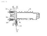
- a shift drum 85 which has an axis thereof arranged parallel to the first and second shafts 44, 45 and the counter shaft 46 is supported on the crankcase 19 in a rotatable manner about an axis of the crankcase 19.
- Shift pins 78a, 79a, 80a, 81 a which are formed on the first to fourth shift forks 78 to 81 respectively in a projecting manner are slidably engaged with first to fourth lead grooves 86, 87, 88, 89 formed on an outer peripheral surface of the shift drum 85.
- a small-diameter shaft portion 85a is coaxially and integrally formed on one end portion of the shift drum 85 in a projecting manner.
- One end portion of the shift drum 85 is rotatably supported on the crankcase 19 by fitting the small-diameter shaft portion 85a into a bottomed support hole 91 formed in the crankcase 19, while the other end portion of the shift drum 85 is rotatably supported on the crankcase 19 by way of a ball bearing 92.
- a stopper plate 93 which is rotated together with the shift drum 85 is fixed to the other end portion of the shift drum 85 by a coaxial bolt 94.
- the stopper plate 93 is rotatably driven intermittently in response to a shift operation by a rider.
- the shift drum 85 is rotated so as to sequentially pass a neutral position where none of the first to sixth gear trains G1 to G6 is established and the first-speed position to the sixth-speed position where one of the first to sixth gear trains G1 to G6 is selectively established.
- the first projection row 98 includes first to third projecting portions 98a, 98b, 98c which are arranged at three portions of the shift drum 85 in a spaced-apart manner in the circumferential direction of the shift drum 85, and three valley portions 98d, 98e, 98f each of which is arranged between each two projecting portions out of the projecting portions 98a, 98b, 98c.
- the first to third projecting portions 98a to 98c are formed on the other end surface of the shift drum 85 in a state where the first to third projecting portions 98a to 98c project in the axial direction from the other end surface of the shift drum 85.
- the second projection row 99 includes fourth to seventh projecting portions 99a, 99b, 99c, 99d which are arranged at a plurality of portions of the shift drum 85 in a spaced-apart manner in the circumferential direction of the shift drum 85, and four valley portions 99e, 99f, 99g, 99h each of which is arranged between each two projecting portions out of the projecting portions 99a to 99d.
- the fourth to seventh projecting portions 99a to 99d are formed on an outer periphery of the other end portion of the shift drum 85 in a state where the fourth to seventh projecting portions 99a to 99d project in the radial direction from the other end portion of the shift drum 85.
- switches are fixedly arranged at positions corresponding to the first and second projection rows 98, 99 on a one by one basis such that a switching mode is changed from an OFF state to an ON state when the switches are brought into contact with the projecting portions 98a to 98c, 99a to 99d of the first and second projection rows 98, 99.
- first and second switches SA, SB are fixedly arranged corresponding to the first projection row 98 used in common by the switches SA, SB.
- the first and second switches SA, SB are fixed to the crankcase 19 while having respective center axes thereof arranged parallel to the axis of the shift drum 85.
- a third switch SC corresponding to the second projection row 99 is fixed to the crankcase 19 while having a center axis thereof arranged orthogonal to the axis of the shift drum 85. Further, the first and the second switches SA, SB are fixedly arranged corresponding to the common first projection row 98 while making phases thereof different from each other. In this embodiment, the second switch SB is arranged at the shift position higher than the shift position of the first switch SA by one speed.
- the first-speed position to the sixth-speed position are arranged in a spaced-apart manner in the circumferential direction while arranging the neutral position between the first-speed position and the second-speed position.
- the first projection row 98 is formed to have the first projecting portion 98a which is detected by the first switch SA at the first-speed position (1 ST) and the neutral position (N), the second projecting portion 98b which is detected by the first switch SA at the second-speed position (2ND), and the third projecting portion 98c which is detected by the first switch SA at the fourth-speed position (4TH).
- the second switch SB detects the first projecting portion 98a at the neutral position and the second-speed position, detects the second projecting portion 98b at the third-speed position (3RD), and detects the third projecting portion 98c at the fifth-speed position (5TH).
- the third projection row 99 is formed to have the fourth projecting portion 99a which is detected by the third switch SC at the neutral position, the fifth projecting portion 99b which is detected by the third switch SC at the third-speed position, the sixth projecting portion 99c which is detected by the third switch SC at the fourth-speed position, and the seventh projecting portion 99d which is detected by the third switch SC at the sixth-speed position (6TH).
- the turning on and off of the first to third switches SA, SB, SC are inputted to an electronic control unit 100 which constitutes a shift position determining means.
- an electronic control unit 100 which constitutes a shift position determining means.
- the electronic control unit 100 determines a shift position by collating the shift position allocated to the detection logic.
- a vehicle-mounted battery is connected to the electronic control unit 100 through a series circuit which is constituted of a main switch 101 for starting the engine E, an engine stop switch 102, a start switch 103 and a first relay coil 104.
- the engine stop switch 102 is a normally-closed switch.
- the first relay coil 104 constitutes a first relay 106 together with a first relay switch 105 arranged between the battery and a starter motor 107.
- a connection point between the first relay coil 104 and the electronic control unit 100 is connected to the ground through a series circuit constituted of a clutch lever switch 108 and a side stand switch 109.
- a connection point between the clutch lever switch 108 and the side stand switch 109 is also connected to the electronic control unit 100 for inputting the turning on and off of the switches 108, 109 to the electronic control unit 100.
- a connection point between the first relay coil 104 and the electronic control unit 100 is connected to the ground through a series circuit which is constituted of a first diode 110, a second relay switch 111, a third relay switch 115 and the second switch SB.
- a series circuit which is constituted of a second relay coil 112 forming a second relay 113 together with the second relay switch 111 and the first switch SA is connected between the battery and the ground.
- a series circuit which is constituted of a third relay coil 116 forming a third relay 117 together with the third relay switch 115 and the third switch SC is arranged between the battery and the ground.
- a connection point between the second relay coil 112 and the first switch SA, a connection point between the third relay switch 115 and the second switch SB, and a connection point between the third relay coil 116 and the third switch SC are connected to the electronic control unit 100 in parallel for inputting the turning on and off of the first, second and third switches SA, SB and SC to the electronic control unit 100.
- a meter unit 120 provided to the motorcycle includes: a vehicle speed meter 121 indicating a vehicle speed; a shift indicator 122 which indicates a shift position based on information from the electronic control unit 100; and a neutral indicator 123 which is turned on when the multi stage transmission M is in a neutral state.
- the neutral indicator 123 is connected to the connection point between the first diode 110 and the second relay switch 111 through a second diode 119.
- the neutral indicator 123 is turned on when the first switch SA is turned on so that the second relay coil 112 is excited whereby the second relay switch 111 is turned on, the third switch SA is turned on so that the third relay switch 115 is excited whereby the third relay switch SC is turned on, and the neutral indicator 123 is turned on when the second switch SB is turned on.
- "1,1,1" is allocated as the detection logic at the neutral position.
- two projection rows 98, 99 which are objects to be detected by two specified switches among the first to third switches SA to SC are formed so as to change switching modes of the specified switches from an OFF state to an ON state and to displace timings at which the specified switches are brought into an ON state from each other.
- the second and third switches SB, SC which constitute two specified switches change switching modes thereof into an ON state from an OFF state.
- the first and second projection rows 98, 99 are formed such that, a rising timing 99i of the fourth projecting portion 99a detected by the third switch SC is set earlier than a rising timing 98g of the first projecting portion 98a detected by the second switch SB.
- the first and third switches SA, SC which constitute two specified switches change switching modes thereof into an ON state from an OFF state.
- the first and second projection rows 98, 99 are formed such that, a rising timing 99j of the fourth projecting portion 99a detected by the third switch SC is set earlier than a rising timing 98h of the first projecting portion 98a detected by the first switch SA.
- the projection row which constitutes an object to be detected by the remaining switch other than the two specified switches is configured to hold a switching mode of the remaining switch in an ON state in at least one of a time during which the shift position is changed to the neutral position from the first speed position and a time during which the shift position is changed to the neutral position from the second speed position.
- the first switch SA which constitutes the remaining switch is fixedly arranged corresponding to the common first projection row 98 while making a phase thereof different from a phase of the second switch SB which constitutes one switch out of the second and third switches SB, SC which are the two specified switches.
- the first projection row 98 which is an object to be detected by the first switch SA is configured to hold the first switch SA in an ON state by bringing the first switch SA into contact with the first projecting portion 98a.
- the second switch SB which constitutes the remaining switch is fixedly arranged corresponding to the common first projection row 98 while making a phase thereof different from a phase of the first switch SA which constitutes one switch out of the first and third switches SA, SC which are two specified switches.
- the first projection row 98 which is an object to be detected by the second switch SB is configured to hold the second switch SB in an ON state by bringing the second switch SB into contact with the first projecting portion 98a as shown in Fig. 7 .
- the multi-stage transmission M includes a positioning means 124 which positions the shift drum 85 at rotary positions corresponding to the respective shift positions.
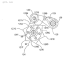
- the positioning means 124 is constituted of the stopper plate 93 which is fixed to the shift drum 85 so as to be rotated together with the shift drum 85, and a roller 125 which constitutes a pressing member resiliently brought into contact with an outer periphery of the stopper plate 93.
- the positioning recessed portions 126A to 126F are arranged equidistantly in the circumferential direction of the stopper plate 93 while individually corresponding to the first-speed position to the sixth-speed position, and the positioning recessed portion 126N is arranged at a center portion between the positioning recessed portions 126A, 126B corresponding to the neutral position between the first speed position and the second speed position.
- the intermediate projecting portion 127A is arranged between the positioning recessed portions 126A, 126N corresponding to the first-speed position and the neutral position.
- the intermediate projecting portion 127B is arranged between the positioning recessed portions 126N, 126B corresponding to the neutral position and the second speed position.
- the intermediate projecting portion 127C is arranged between the positioning recessed portions 126B, 126C corresponding to the second-speed position and the third-speed position.
- the intermediate projecting portion 127D is arranged between the positioning recessed portions 126C, 126D corresponding to the third-speed position and the fourth-speed position.
- the intermediate projecting portion 127E is arranged between the positioning recessed portions 126D, 126E corresponding to the fourth-speed position and the fifth-speed position.
- the intermediate projecting portion 127F is arranged between the positioning recessed portions 126E, 126F corresponding to the fifth-speed position and the sixth-speed position.
- the intermediate projecting portion 127G is arranged between the positioning recessed portions 126F, 126A corresponding to the sixth-speed position and the first-speed position.
- the roller 125 is rotatably supported on the other end portion of a stopper arm 129 which has one end portion thereof rotatably supported on the crank case 19 by way of a support shaft 128.
- a torsional spring 130 which rotatably biases the stopper arm 129 is arranged on a side where the roller 125 is pressed to an outer periphery of the stopper arm 93.
- the multi-stage transmission M is configured to establish the first-speed gear train G1 and the second-speed gear train G2 by making the first and fourth shifters 72, 77 engage with the first-speed drive gear 62 and the second-speed driven gear 68 which respectively constitute portions of at least one of the first-speed gear train G1 and the second-speed gear train G2, in this embodiment, both of the first-speed gear train G1 and the second-speed gear train G2.
- a switching timing of the engagement of the first and fourth shifters 72, 77 with the first-speed drive gear 62 and the second-speed driven gear 68 and releasing of the engagement is set as follows.
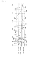
- Fig. 10 assume the neutral position as an angle "0", a first-speed side as a minus side, and a second-speed side as a plus side.
- the engagement of the first shifter 72 with the first-speed drive gear 62 is released when the shift position is changed to the neutral position from the first speed at an angle (- ⁇ 2) on a more neutral position side than an angle (- ⁇ 3) at which the engagement of the first shifter 72 with the first-speed drive gear 62 is started when the shift position is changed to the first-speed position from the neutral position.
- the second switch SB is turned on when the shift position is changed to the neutral position from the first-speed position at an angle (- ⁇ 1) on a more neutral position side than these angles (- ⁇ 3, - ⁇ 2).
- the second switch SB and the third switch SC constitute two specified switches, and a timing at which a switching mode of the second switch SB which is one specified switch out of these two specified switches is brought into an ON state from an OFF state is set on a more neutral position side than a switching timing of the engagement of the first shifter 72 with the first drive gear 62 and a timing of the releasing of the engagement.
- the engagement of the fourth shifter 77 with the second-speed driven gear 68 is released when the shift position is changed to the neutral position from the second-speed position at an angle ⁇ 6 on a more neutral position side than an angle ⁇ 7 at which the engagement of the fourth shifter 77 with the second-speed driven gear 68 is started when the shift position is changed to the second-speed position from the neutral position.
- the first switch SA is turned on when the shift position is changed to the neutral position from the second-speed position at an angle ⁇ 5 on a more neutral position side than these angles ⁇ 7, ⁇ 6.
- the first switch SA and the third switch SC constitute two specified switches, and a timing at which a switching mode of the first switch SA which is one specified switch out of these two specified switches is brought into an ON state from an OFF state is set on a more neutral position side than a switching timing of the engagement of the second shifter 77 with the second driven gear 68 and a switching timing of the releasing of the engagement.
- a timing at which a switching mode of the third switch SC which constitutes the other specified switch out of the above-mentioned two specified switches SB, SC: SA, SC is brought into an ON state from an OFF state is arranged simultaneously with the above-mentioned switching timing or on a side more away from the neutral position than the switching timing.
- the switching mode of the third switch SC is brought into an ON state from an OFF state at an angle (- ⁇ 4) more away from the neutral position than the switching timing between the engagement of the first shifter 72 with the first drive gear 62 and the releasing of the engagement.
- the switching mode of the third switch SC is brought into an ON state from an OFF state at an angle ⁇ 8 on a side more away from the neutral position than the switching timing of the engagement of the fourth shifter 77 with the second driven gear 68 and the switching timing of the releasing of the engagement.
- the roller 125 is brought into contact with a top point of the intermediate projecting portion 127A corresponding to a position between the first speed position and the neutral position out of the plurality of intermediate projecting portions 127A to 127G formed on the stopper plate 93 of the positioning means 124 which the multi-stage transmission M includes within a range indicated by W1 in Fig. 10 .
- the roller 125 is brought into contact with a top portion of the intermediate projecting portion 127B corresponding to a position between the second-speed position and the neutral position out of the plurality of intermediate projecting portions 127A to 127G within a range indicated by W2 in Fig. 10 .
- a timing at which a switching mode of the third switch SC which constitutes the other specified switch out of the above-mentioned two specified switches SB, SC between the first-speed position and the neutral position is brought into an ON state from an OFF state and a timing at which a switching mode of the third switch SC which constitutes the other specified switch out of the above-mentioned two specified switches SA, SC between the second speed position and the neutral position is brought into an ON state from an OFF state are set on a side away from the neutral position than a timing at which the roller 125 is brought into contact with the top point of the intermediate projecting portion 127A corresponding to the position between the first speed position and the neutral position or a timing at which the roller 125 is brought into contact with the top point of the intermediate projecting portion 127B corresponding to the position between the neutral position and the second speed position.
- the switching mode of the third switch SC between the first speed position and the neutral position is brought into an ON state from an OFF state at an angle (- ⁇ 4) on a side opposite to the neutral position with respect to the range W1
- the switching mode of the third switch SC between the second speed position and the neutral position is brought into an ON state from an OFF state at an angle ⁇ 8 on a side opposite to the neutral position with respect to the range W2.
- the first and second projection rows 98, 99 which are objects to be detected by two specified switches among the first to third switches SA to SC
- the second and third switches SB, SC which are the specified switches when the shift position is changed to the neutral position from the first-speed position and the first and third switches SA, SC which are the specified switches when the shift position is changed to the neutral position from the second-speed position
- the specified switches SB, SC; SA, SC
- the second switch SB When the shift position is changed to the neutral position from the first-speed position, as shown in Fig. 13(a) , the second switch SB is disposed at a position corresponding to a valley portion 98f of the first projection row 98 and, at the same time, the third switch SC is disposed at a position corresponding to a valley portion 99h of the second projection row 99 so that the switching modes of both the second switch SB and the third switch SC are in an OFF state. Then, as shown in Fig. 13(b) , the switching modes of the second switch SB and the third switch SC are brought into an ON state from an OFF state. Through this switching mode changeover period, as shown in Fig.
- the second switch SB is brought into contact with a top portion of the first projecting portion 98a of the first projection row 98 so that the second switch SB is held in an ON state and, at the same time, the third switch SC is brought into contact with a top portion of the fourth projecting portion 99a of the second projection row 99 so that the third switch SC is held in an ON state.
- the friction resistance generated in the state shown in Fig. 13(b) is liable to become larger than the friction resistance generated in the state shown in Fig. 13(c) .
- the first projecting portion 98a and the fourth projecting portion 99a are worn due to the contact thereof with the second and third switches SB, SC, and the wear is liable to be accelerated also due to sparks generated between the first and forth projecting portions 98a, 99a and the second and third switches SB, SC whereby the wear in the state shown in Fig. 13(b) is liable to be increased with time. The same goes for the change of the shift position from the second-speed position to the neutral position.
- the multi-stage transmission M is configured such that the first shifter 72 is engaged with the first-speed drive gear 62 which constitutes a part of the first-speed gear train G1 so as to establish the first-speed gear train G1, and the fourth shifter 77 is engaged with the second-speed driven gear 68 which constitutes a part of the second-speed gear train G2 so as to establish the second-speed gear train G2.
- a timing at which a switching mode of the second switch SB or the first switch SA which constitutes one specified switch out of two specified switches SB, SC: SA, SC is brought into an ON state from an OFF state is set on a more neutral position side than a switching timing of the engagement of the first and fourth shifters 72, 77 with the first-speed drive gear 62 and the second-speed driven gear 68 and a switching timing of the releasing of the engagement.
- a timing at which the switching mode of the third switch SC which constitutes the other specified switch is brought into an ON state from an OFF state is arranged simultaneously with the switching timing or on a side more away from the neutral position than the switching timing. Accordingly, in a state where the neutral position is detected, the first and the fourth shifters 72, 77 are surely brought into an engagement release state and hence, the degree of freedom in setting a timing at which the third switch SC is brought into an ON state is enhanced.
- the positioning means 124 which the multi-stage transmission M includes: the stopper plate 93 which is fixed to the shift drum 85 so as to be rotated together with the shift drum 85 and has the outer periphery on which the plurality of positioning recessed portions 126A, 126B, 126C, 126D, 126E, 126F, 126N corresponding to the respective shift positions and the plurality of intermediate projecting portions 127A, 127B, 127C, 127D, 127E, 127F, 127G each of which is arranged between each two positioning recessed portions 126A to 126F, 126N are formed; and the roller 125 which is resiliently brought into contact with the outer periphery of the stopper plate 93.
- the timing at which the switching mode of the third switch SC is brought into an ON state from an OFF state is set on a side more away from the neutral position than a timing at which the roller 125 is brought into contact with a top point of the intermediate projecting portion 127A corresponding to a position between the first-speed position and the neutral position and a timing at which the roller 125 is brought into contact with a top point of the intermediate projecting portion 127B corresponding to a position between the neutral position and the second-speed position.
- timings at which the roller 125 is brought into contact with the top points of the intermediate projecting portions 127A, 127B are timings at which a friction generated when the shift drum 85 is rotated becomes large
- bringing the third switch SC into an ON state at the timing displaced from the timings at which the roller 125 is brought into contact with the top points of the intermediate projecting portions 127A, 127B when the shift position is changed to the neutral position it is possible to prevent a change in friction from being increased thus giving a rider an operation feeling with no discomfort.
- the first projection row 98 which is the projection row constituting an object to be detected by the remaining switch other than two specified switches SB, SC: SA, SC, that is, the first switch SA when the shift position is changed to the neutral position from the first-speed position and the second switch SB when the shift position is changed to the neutral position from the second-speed position is configured to hold a switching mode of the remaining switch SA, SB in an ON state in at least one of a time during which the shift position is changed to the neutral position from the first-speed position and a time during which the shift position is changed to the neutral position from the second-speed position.
- the remaining switch SA, SB is held in an ON state when the shift position is changed to the neutral position from the first-speed position and the second-speed position and hence, there is no timing at which a friction is increased. Accordingly, in setting timings at which two specified switches SB, SC: SA, SC are brought into an ON state, it is unnecessary to take into account a timing at which the remaining switch SA, SB is brought into an ON state whereby the degree of freedom in setting timings at which two specified switches SA, SB are brought into an ON state.
- the second switch SB which constitutes one switch out of two specified switches SB, SC and the first switch SA which constitutes the remaining switch are fixedly arranged corresponding to the common first projection row 98 while making phases thereof different from each other.
- the third switch SC which constitutes one switch out of two specified switches SA, SC and the first switch SA which constitutes the remaining switch are fixedly arranged corresponding to the common first projection row 98 while making phases thereof different from each other.
- the remaining switch other than two specified switches among three switches SA to SC is held in an ON state when the shift position is changed to the neutral position from both the first-speed position and the second-speed position and hence, there is no timing at which a friction is increased.
- the one switch out of two specified switches and the remaining switches correspond to one common projection row 98 while making phases thereof different from each other and hence, it is possible to minimize a change in friction when the shift drum 85 is rotated while minimizing the number of projection rows to 2, that is, projection rows 98, 99.
- the multi-stage transmission M mounted on a motorcycle is explained in the above-mentioned embodiment.
- the invention is also applicable to a multi-stage transmission mounted on a three-wheeled motorcycle or a four-wheeled vehicle.
- It is the object of the invention to provide a shift position detecting device where a shift position determining means is provided for determining a shift position based on a combination of switching modes of three switches corresponding to at least one of a plurality of projection rows each having a plurality of projection portions in a one-by-one basis, and "1, 1, 1" indicative of an ON state of each switch is allocated as a detection logic at a neutral position arranged between a first speed position and a second speed position, wherein a change in friction at the time of a shift operation to the neutral position is alleviated thus giving an operation feeling with no discomfort to a rider.
Abstract
Description
- The present invention relates to a shift position detecting device which includes: a plurality of projection rows each of which includes projecting portions arranged at a plurality of places in a spaced-apart manner in the circumferential direction of a shift drum constituting a part of a multi-stage transmission having gear trains of a plurality of shift stages which are selectively establishable, and are mounted on the shift drum; three switches which are fixedly arranged at least one by one corresponding to the plurality of projection rows such that a switching mode is changed from an OFF state to an ON state by being brought into contact with the projecting portions; and a shift position determining means which determines a shift position by collating the shift position allocated to the detection logic based on the detection logic which is formed of "1" generated when the switches are in an ON state and "0" generated when the switches are in an OFF state, wherein "1, 1, 1" is allocated as the detection logic at a neutral position arranged between a first speed position and a second speed position.
-
JP-A-2011-196517 - A friction is increased at a moment that the switch is brought into contact with the projecting portion of the projection row of the shift drum. However, when timings at which the plurality of switches come into contact with the projecting portions are equal, a friction caused by the contact of the switch to the projecting portion occurs simultaneously with respect to the plurality of the switches and hence, the movement of the shift drum is liable to be obstructed. Particularly, in the shift position detecting device disclosed in the above-mentioned
JP-A-2011-196517 - The invention has been made in view of such circumstances, and it is an object of the invention to provide a shift position detecting device which allows a rider to have an operation feeling with no discomfort by alleviating a change in friction at the time of performing a shift operation to a neutral position.
- To achieve the above-mentioned object, according to the first technical feature of the invention, there is provided a shift position detecting device which includes: a plurality of projection rows each of which includes projecting portions arranged at a plurality of places in a spaced-apart manner in the circumferential direction of a shift drum constituting a part of a multi-stage transmission having gear trains of a plurality of shift stages which are selectively establishable, and are mounted on the shift drum; three switches which are fixedly arranged at least one by one corresponding to the plurality of projection rows such that a switching mode is changed from an OFF state to an ON state by being brought into contact with the projecting portions; and a shift position determining means which determines a shift position by collating the shift position allocated to the detection logic based on the detection logic which is formed of a combination of "1" generated when the switches are in an ON state and "0" generated when the switches are in an OFF state, wherein "1, 1, 1" is allocated as the detection logic at a neutral position arranged between a first speed position and a second speed position, wherein the two projection rows which are objects to be detected by the two specified switches among the three switches are formed so as to change switching modes of the specified switches from an OFF state to an ON state and to displace timings at which the specified switches are brought into an ON state from each other when the shift position is changed from at least one of the first speed position and the second speed position to the neutral position.
- According to the second technical feature of the invention, in addition to the first technical feature of the invention, the multi-stage transmission is configured such that a shifter is engaged with a gear which constitutes a part of at least one of the first-speed gear train and the second-speed gear train so as to establish at least one of the first-speed gear train and the second-speed gear train, a timing at which a switching mode of one specified switch out of the two specified switches is brought into an ON state from an OFF state is set on a more neutral position side than switching timings of engagement of the shifter with the gear and releasing of the engagement, and a timing at which a switching mode of the other specified switch is brought into an ON state from an OFF state is arranged simultaneously with the switching timing or on a side more away from the neutral position than the switching timing.
- According to the third technical feature of the invention, in addition to the second technical feature of the invention, the multi-stage transmission includes a positioning means which positions the shift drum at rotary positions corresponding to respective shift positions, the positioning means includes: a stopper plate which is fixed to the shift drum so as to be rotated together with the shift drum and has an outer periphery on which a plurality of positioning recessed portions corresponding to the respective shift positions and a plurality of intermediate projecting portions each of which is arranged between each two positioning recessed portions are formed; and a pressing member which is resiliently brought into contact with an outer periphery of the stopper plate, and a timing at which the switching mode of the other specified switch is brought into an ON state from an OFF state is set on a side more away from the neutral position than a timing at which the pressing member is brought into contact with a top point of the intermediate projecting portion corresponding to a position between the first-speed position and the neutral position or a timing at which the pressing member is brought into contact with a top point of the intermediate projecting portion corresponding to a position between the neutral position and the second-speed position.
- According to the fourth technical feature of the invention, in addition to the second or third technical feature of the invention, the projection row which constitutes an object to be detected by the remaining switch other than the two specified switches is configured to hold a switching mode of the remaining switch in an ON state in at least one of a time during which a shift position is changed to the neutral position from the first-speed position and a time during which the shift position is changed to the neutral position from the second-speed position.
- According to the fifth technical feature of the invention, in addition to the fourth technical feature of the invention, the projection row which constitutes an object to be detected by the remaining switch is configured to hold a switching mode of the remaining switch in an ON state in the time during which the shift position is changed to the neutral position from the first-speed position and the time during which the shift position is changed to the neutral position from the second-speed position, and one switch out of the two specified switches and the remaining switch are fixedly arranged corresponding to one common projection row while making phases thereof different from each other.
- According to the first technical feature of the invention, when the shift position is changed to the neutral position from at least one of the first-speed position and the second-speed position, a switching mode is changed to an ON state from an OFF state while displacing timings at which two specified switches are brought into an ON state from each other. Accordingly, there is no possibility that two specified switches are simultaneously brought into contact with the projecting portions of the projection row which constitute objects to be detected by these two specified switches and hence, a change in friction when the shift drum is rotated toward a neutral position side can be alleviated whereby it is possible to give a rider an operation feeling with no discomfort.
- According to the second technical feature of the invention, one specified switch is brought into an ON state on a more neutral position side than switching timing of engagement of the shifter with the gear and releasing of the engagement at the time of establishing at least one of the first-speed gear train and the second-speed gear train. Accordingly, in a state where the neutral position is detected, the shifter is surely brought into an engagement released state and hence, by setting a timing at which the other specified switch is brought into an ON state simultaneously with the switching timing or on a side more away from the neutral position than the switching timing, the degree of freedom in setting the timing at which the other specified switch is brought into an ON state is enhanced.
- According to the third technical feature of the invention, the multi-stage transmission includes the positioning means which includes: the stopper plate which is rotated together with the shift drum in a state where the plurality of positioning recessed portions corresponding to the respective shift positions and the plurality of intermediate projecting portions each of which is arranged between each two positioning recessed portions are formed on the outer periphery of the stopper plate; and the pressing member which is resiliently brought into contact with an outer periphery of the stopper plate. While the timing at which the pressing member is brought into contact with the top point of the intermediate projecting portion becomes the timing at which a friction is increased when the shift drum is rotated, a timing at which the other specified switch is brought into an ON state at the neutral position is set on a side more away from the neutral position than a timing at which the pressing member is brought into contact with the top point of the intermediate projecting portion corresponding to a position between the first-speed position and the neutral position or a top point of the intermediate projecting portion corresponding to a position between the second-speed position and the neutral position. Accordingly, at the time that the shift position is changed to the neutral position, the other specified switch is brought into an ON state at the timing displaced from the timing at which the pressing member is brought into contact with the top point of the intermediate projecting portion and hence, it is possible to prevent a change in friction from being increased whereby it is possible to give a rider an operation feeling with no discomfort.
- According to the fourth technical feature of the invention, among three switches, the remaining switch other than two specified switches is held in an ON state when the shift position is changed to the neutral position from at least one of the first-speed position and the second-speed position and hence, there is no timing at which a friction is increased. Accordingly, in setting a timing at which two specified switches are brought into an ON state, it is unnecessary to take into account the timing at which the remaining switch is brought into an ON state and hence, the degree of freedom in setting a timing at which two specified switches are brought into an ON state can be enhanced.
- According to the fifth technical feature of the invention, among three switches, the remaining switch other than two specified switches is held in an ON state when the shift position is changed to the neutral position from both the first-speed position and the second-speed position and hence, there is no timing at which a friction is increased. Further, one switch out of the two specified switches and the remaining switch correspond to one common projection row while having different phases and hence, a change in friction at the time of rotating the shift drum can be minimized while suppressing the number of the projection rows to a minimum value of 2.
-
-
Fig .1 is a side view of a motorcycle to which the invention is applied. -
Fig .2 is a cross-sectional view taken along a line 2-2 inFig. 1 . -
Fig .3 is a vertical cross-sectional side view showing the arrangement of three switches and a shift drum in a simplified manner. -
Fig .4 is a view taken as viewed in an arrow direction from a line 4-4 inFig. 3 . -
Fig .5 is a cross-sectional view taken along a line 5-5 inFig. 3 . -
Fig .6 is a view as viewed in the direction indicated by anarrow 6 inFig. 2 . -
Fig .7 is a view showing the relationship between first and second projection rows and first to third switches developed in the circumferential direction of a shift drum. -
Fig .8 is a view showing the constitution of an electronic circuit for determining a shift position. -
Fig .9 is a view as viewed in the direction indicated by anarrow 9 inFig. 2 . -
Fig .10 is a view showing a timing of engagement of a shifter and a timing of releasing the engagement, an operation timing of a positioning means, and switching mode switching timings of respective switches between a first-speed position and a second-speed position in comparison. -
Fig .11 is a view corresponding toFig. 9 in a state where a roller is brought into contact with a top point of an intermediate projecting portion between a first-speed position and a neutral position. -
Fig .12 is a view corresponding toFig. 9 in a state where the roller is brought into contact with a top point of an intermediate projecting portion between a second-speed position and the neutral position. -
Fig .13 is a view for explaining a friction generated by a contact between the switch and the projection. - Hereinafter, an embodiment of the invention is explained by reference to
Fig. 1 to Fig. 13 attached herewith. Firstly, inFig. 1 , a vehicle body frame F of a motorcycle includes: ahead pipe 12 which steerably supports a front fork 11 which pivotally supports a front wheel WF; amain frame 13 which extends rearward and downward from thehead pipe 12; an engine hanger 14 which extends downward from a front portion of themain frame 13; apivot frame 15 which extends downward from a rear portion of themain frame 13; and aseat rail 16 which extends rearward and upward from the rear portion of themain frame 13. - An
engine body 17 of an engine E which is arranged below themain frame 13 is supported on the rear portion of themain frame 13, a lower portion of the engine hanger 14 and a lower portion of thepivot frame 15 of the vehicle body frame F. A rear wheel WR driven by power which the engine E generates is pivotally supported on a rear end portion of aswing arm 18. A front end portion of theswig arm 18 is supported on thepivot frame 15 in a vertically swingable manner. Afuel tank 24 is mounted on themain frame 13 above the engine E. A rider'sseat 25 arranged behind thefuel tank 24 is supported on theseat rail 16. - A part of the engine E and a part of the vehicle body frame F are covered with a
vehicle body cover 27. Thevehicle body cover 27 includes: afront cowl 28; a pair of left and right side covers 29 which covers a rear lower portion of thefuel tank 24 from both sides and is arranged between thefuel tank 24 and the rider'sseat 25; and arear cowl 30 which is contiguously formed with rear portions of bothside covers 29 and extends rearward and upward. - The
engine body 17 of the engine E includes: acrankcase 19 which rotatably supports acrankshaft 23 having an axis extending in the width direction of the vehicle body frame F; acylinder body 20 which is joined to an upper end of a front portion of thecrankcase 19 with a cylinder axis thereof inclined frontward; acylinder head 21 which is joined to an upper end of thecylinder body 20; and ahead cover 22 which is joined to an upper end of thecylinder head 21. - An
exhaust system 31 which is connected to a side surface of a front portion of thecylinder head 21 includes anexhaust muffler 32 on a rear end thereof, and theexhaust muffler 32 is arranged on a right side of the rear wheel WR. A side surface of a rear portion of thecylinder head 21 faces in the oblique rearward and upward direction. Anintake system 33 connected to a side surface of the rear portion of thecylinder head 21 includes: anair cleaner 34 which is arranged above thehead cover 22 in a state where theair cleaner 34 is covered with thefuel tank 24; and athrottle device 35 which is interposed between theair cleaner 34 and thecylinder head 21. - In
Fig. 2 , a sequential-type multistage transmission M is housed in the inside of thecrankcase 19. The multistage transmission M is configured such that gear trains of a plurality of shift stages, for example, first-speed to sixth-speed gear trains G1 to G6 which are selectively establishable are arranged between a main shaft 43 and acounter shaft 46. An axis of the main shaft 43 and an axis of thecounter shaft 46 are arranged parallel to thecrankshaft 30. One end of thecounter shaft 46 projects from a side surface of the rear portion of thecrankcase 19, and rotational power outputted from thecounter shaft 46 is transmitted to the rear wheel WR which constitutes a drive wheel by way of a power transmission means 38 as shown inFig. 1 . The power transmission means 38 is constituted such that anendless drive chain 41 extends between and is wound around adrive sprocket 39 fixed to a shaft end of thecounter shaft 46 and a drivensprocket 40 mounted on the rear wheel WR coaxially. - The main shaft 43 is constituted of a
first shaft 44 and asecond shaft 45 which allows thefirst shaft 44 to coaxially pass therethrough in a relatively rotatable manner. The first-speed gear train G1, the third-speed gear train G3 and the fifth-speed gear train G5 are arranged between thefirst shaft 44 and thecounter shaft 46, while the second-speed gear train G2, the fourth-speed gear train G4 and the sixth-speed gear train G6 are arranged between thesecond shaft 45 and thecounter shaft 46. - The
first shaft 44 has a smaller diameter than thesecond shaft 45. One end portion of thefirst shaft 44 is rotatably supported on thecrankcase 19 by way of a ball bearing 47. The other end side of thefirst shaft 44 rotatably penetrates thecrankcase 19, and the other end portion of thefirst shaft 44 is rotatably supported on acrankcase cover 48 which is fastened to thecrankcase 19 by way of a clutch inner 60 and a ball bearing 49. Thesecond shaft 45 having a larger diameter than thefirst shaft 44 is rotatably supported on thecrankcase 19 by way of aball bearing 50. An intermediate portion of thefirst shaft 44 coaxially passes through thesecond shaft 45 in a relatively rotatable manner, and a plurality ofneedle bearings 51 are interposed between thefirst shaft 44 and thesecond shaft 45. - A power transmission cylindrical shaft 53 which is arranged adjacent to the
second shaft 45 in the axial direction is mounted on the other end side of thefirst shaft 44 in a relatively rotatable manner, and power transmitted from thecrankshaft 30 is transmitted to the power transmission cylindrical shaft 53 by way of a primaryspeed reduction device 54 and adamper spring 57. The primaryspeed reduction device 54 is constituted of a drive gear (not shown in the drawing) which is rotated together with thecrankshaft 30, and a drivengear 56 which is arranged coaxially with the first andsecond shafts gear 56 is meshed with the drive gear. The drivengear 56 is connected to the power transmission cylindrical shaft 53 by way of thedamper spring 57. - A first hydraulic clutch 58 is arranged between the power transmission cylindrical shaft 53 and the
first shaft 44, the clutch inner 60 which the first hydraulic clutch 58 includes is connected to the other end portion of thefirst shaft 44 in a relatively non-rotatable manner, and theball bearing 49 is interposed between the clutch inner 60 and thecrankcase cover 48. A second hydraulic clutch 59 which sandwiches the primaryspeed reduction device 54 between the second hydraulic clutch 59 and the first hydraulic clutch 58 is arranged between the power transmission cylindrical shaft 53 and thesecond shaft 45. - When the first hydraulic clutch 58 is in a power transmission state so that power is transmitted to the
first shaft 44 from thecrankshaft 30, power can be transmitted to thecounter shaft 46 from thefirst shaft 44 by way of the gear train selectively established from the first-speed, third-speed and fifth-speed gear trains G1, G3 and G5. When the second hydraulic clutch 59 is in a power transmission state so that power is transmitted to thesecond shaft 45 from thecrankshaft 30, power can be transmitted to thecounter shaft 46 from thesecond shaft 45 by way of the gear train selectively established from the second-speed, fourth-speed and sixth-speed gear trains G2, G4 and G6. - The first-speed, third-speed and fifth-speed gear trains G1, G3 and G5 are arranged between a portion of the
first shaft 44 which sandwiches thesecond shaft 45 with the first and secondhydraulic clutches first shaft 44 on one end side which projects from thesecond shaft 45 and thecounter shaft 46. The first-speed gear train G1 is constituted of a first-speed drive gear 61 which is integrally formed with thefirst shaft 44, and a first-speed drivengear 62 which is supported on thecounter shaft 46 in a relatively non-rotatable manner and is meshed with the first-speed drive gear 61. The third-speed gear train G3 is constituted of a third-speed drive gear 63 which is joined to thefirst shaft 44 in a relatively non-rotatable manner while being slidable in the axial direction, and a third-speed drivengear 64 which is supported on thecounter shaft 46 in a relatively rotatable manner and is meshed with the third-speed drive gear 63. The fifth-speed gear train G5 is constituted of a fifth-speed drive gear 65 which is arranged between the first-speed and third-speed drive gears 61, 63 and is supported on thefirst shaft 44 in a relatively rotatable manner, and a fifth-speed drivengear 66 which is joined to thecounter shaft 46 in a relatively non-rotatable manner while being slidable in the axial direction and is meshed with the fifth-speed drive gear 65. - The second-speed gear train G2 is constituted of a second-
speed drive gear 67 which is integrally formed with thesecond shaft 45, and a second-speed drivengear 68 which is supported on thecounter shaft 46 in a relatively rotatable manner and is meshed with the second-speed drive gear 67. The fourth-speed gear train G4 is constituted of a fourth-speed drive gear 69 which is joined to thesecond shaft 45 in a relatively non-rotatable manner while being slidable in the axial direction, and a fourth-speed driven gear 70 which is supported on thecounter shaft 46 in a relatively rotatable manner and is meshed with the fourth-speed drive gear 69. The sixth-speed gear train G6 is constituted of a sixth-speed drive gear 71 which is arranged between the second-speed and fourth-speed drive gears 67, 69 and is supported on thesecond shaft 45 in a relatively rotatable manner, and a sixth-speed drivengear 72 which is joined to thecounter shaft 46 in a relatively non-rotatable manner while being slidable in the axial direction and is meshed with the sixth-speed drive gear 71. - A
first shifter 74 is supported on thecounter shaft 46 in a relatively non-rotatable manner and in an axially slidable manner between the first-speed drivengear 62 and the third-speed drivengear 64, and the fifth-speed drivengear 66 is integrally formed with thefirst shifter 74. Thefirst shifter 74 is slidable among a position where thefirst shifter 74 is engaged with the first-speed drivengear 62, a position where thefirst shifter 74 is engaged with the third-speed drivengear 64, and a position where thefirst shifter 74 is engaged with neither the first-speed drivengear 62 nor the third-speed drivengear 64. Asecond shifter 75 is supported on thefirst shaft 44 in a relatively non-rotatable manner and in an axially slidable manner in a state where thesecond shifter 75 sandwiches the fifth-speed drive gear 65 between thesecond shifter 75 and the first-speed drive gear 61, and the third-speed drive gear 63 is integrally formed with thesecond shifter 75. Thesecond shifter 75 is slidable between a position where thesecond shifter 75 is engaged with the fifth-speed drive gear 65 and a position where the engagement between thesecond shifter 75 and the fifth-speed drive gear 65 is released. - When the
first shifter 74 is engaged with the first-speed drivengear 62 in a state where thesecond shifter 75 is not engaged with the fifth-speed drive gear 65, the first-speed gear train G1 is established. When thefirst shifter 74 is engaged with the third-speed drivengear 64 in a state where thesecond shifter 75 is not engaged with the fifth-speed drive gear 65, the third-speed gear train G3 is established. When thesecond shifter 75 is engaged with the fifth-speed drive gear 65 in a state where thefirst shifter 74 is engaged with neither the first-speed drivengear 62 nor the third-speed drivengear 64, the fifth-speed gear train G5 is established. - A
third shifter 76 is supported on thesecond shaft 45 in a relatively non-rotatable manner and in an axially slidable manner in a state where the sixth-speed drive gear 71 is sandwiched between thethird shifter 76 and the second-speed drive gear 67. The fourth-speed drive gear 69 is integrally formed with thethird shifter 76. Thethird shifter 76 is slidable between a position where thethird shifter 76 is engaged with the sixth-speed drive gear 71 and a position where the engagement between thethird shifter 76 and the sixth-speed drive gear 71 is released. Further, a fourth shifter 77 is supported on thecounter shaft 46 in a relatively non-rotatable manner and in an axially slidable manner between the second-speed drivengear 68 and the fourth-speed driven gear 70. The sixth-speed drivengear 72 is integrally formed with the fourth shifter 77. The fourth shifter 77 is slidable among a position where the fourth shifter 77 is engaged with the second-speed drivengear 68, a position where the fourth shifter 77 is engaged with the fourth-speed driven gear 70, and a position where the fourth shifter 77 is engaged with neither the second-speed drivengear 68 nor the fourth-speed driven gear 70. - When the fourth shifter 77 is engaged with the second-speed driven
gear 68 in a state where thethird shifter 76 is not engaged with the sixth-speed drive gear 71, the second-speed gear train G2 is established. When the fourth shifter 77 is engaged with the fourth-speed driven gear 70 in a state where thethird shifter 76 is not engaged with the sixth-speed drive gear 71, the fourth-speed gear train G4 is established. When thethird shifter 75 is engaged with the sixth-speed drive gear 71 in a state where the fourth shifter 77 is engaged with neither the second-speed drivengear 68 nor the fourth-speed driven gear 70, the sixth-speed gear train G6 is established. - The first to
fourth shifters fourth shift forks fourth shift forks shift fork shaft 82 in an axially slidable manner. The second andthird shift forks shift fork shaft 83 in an axially slidable manner. The first and secondshift fork shafts crankcase 19 while having respective axes thereof arranged parallel to the first andsecond shafts counter shaft 46. - A
shift drum 85 which has an axis thereof arranged parallel to the first andsecond shafts counter shaft 46 is supported on thecrankcase 19 in a rotatable manner about an axis of thecrankcase 19. Shift pins 78a, 79a, 80a, 81 a which are formed on the first tofourth shift forks 78 to 81 respectively in a projecting manner are slidably engaged with first tofourth lead grooves shift drum 85. When theshift drum 85 is rotated, the first tofourth shift forks 78 to 81 slide in the axial direction in accordance with patterns of the first tofourth lead grooves 86 to 89. - A small-
diameter shaft portion 85a is coaxially and integrally formed on one end portion of theshift drum 85 in a projecting manner. One end portion of theshift drum 85 is rotatably supported on thecrankcase 19 by fitting the small-diameter shaft portion 85a into a bottomedsupport hole 91 formed in thecrankcase 19, while the other end portion of theshift drum 85 is rotatably supported on thecrankcase 19 by way of aball bearing 92. - A
stopper plate 93 which is rotated together with theshift drum 85 is fixed to the other end portion of theshift drum 85 by acoaxial bolt 94. Thestopper plate 93 is rotatably driven intermittently in response to a shift operation by a rider. When theshift drum 85 is rotatably driven together with thestopper plate 93, theshift drum 85 is rotated so as to sequentially pass a neutral position where none of the first to sixth gear trains G1 to G6 is established and the first-speed position to the sixth-speed position where one of the first to sixth gear trains G1 to G6 is selectively established. - In
Fig. 3 andFig. 4 , a plurality of projection rows (the first andsecond projection rows shift drum 85. Thefirst projection row 98 includes first to third projectingportions shift drum 85 in a spaced-apart manner in the circumferential direction of theshift drum 85, and threevalley portions portions portions 98a to 98c are formed on the other end surface of theshift drum 85 in a state where the first to third projectingportions 98a to 98c project in the axial direction from the other end surface of theshift drum 85. - To explain this embodiment also by reference to
Fig. 5 , thesecond projection row 99 includes fourth to seventh projectingportions shift drum 85 in a spaced-apart manner in the circumferential direction of theshift drum 85, and fourvalley portions portions 99a to 99d. The fourth to seventh projectingportions 99a to 99d are formed on an outer periphery of the other end portion of theshift drum 85 in a state where the fourth to seventh projectingportions 99a to 99d project in the radial direction from the other end portion of theshift drum 85. - To explain this embodiment also by reference to
Fig. 6 , switches are fixedly arranged at positions corresponding to the first andsecond projection rows portions 98a to 98c, 99a to 99d of the first andsecond projection rows first projection row 98 used in common by the switches SA, SB. The first and second switches SA, SB are fixed to thecrankcase 19 while having respective center axes thereof arranged parallel to the axis of theshift drum 85. A third switch SC corresponding to thesecond projection row 99 is fixed to thecrankcase 19 while having a center axis thereof arranged orthogonal to the axis of theshift drum 85. Further, the first and the second switches SA, SB are fixedly arranged corresponding to the commonfirst projection row 98 while making phases thereof different from each other. In this embodiment, the second switch SB is arranged at the shift position higher than the shift position of the first switch SA by one speed. - To explain this embodiment also by reference to
Fig. 7 , on theshift drum 85, the first-speed position to the sixth-speed position are arranged in a spaced-apart manner in the circumferential direction while arranging the neutral position between the first-speed position and the second-speed position. Thefirst projection row 98 is formed to have the first projectingportion 98a which is detected by the first switch SA at the first-speed position (1 ST) and the neutral position (N), the second projectingportion 98b which is detected by the first switch SA at the second-speed position (2ND), and the third projectingportion 98c which is detected by the first switch SA at the fourth-speed position (4TH). On the other hand, the second switch SB detects the first projectingportion 98a at the neutral position and the second-speed position, detects the second projectingportion 98b at the third-speed position (3RD), and detects the third projectingportion 98c at the fifth-speed position (5TH). Thethird projection row 99 is formed to have the fourth projectingportion 99a which is detected by the third switch SC at the neutral position, the fifth projectingportion 99b which is detected by the third switch SC at the third-speed position, the sixth projectingportion 99c which is detected by the third switch SC at the fourth-speed position, and the seventh projectingportion 99d which is detected by the third switch SC at the sixth-speed position (6TH). - In
Fig. 8 , the turning on and off of the first to third switches SA, SB, SC are inputted to anelectronic control unit 100 which constitutes a shift position determining means. Based on a detection logic which is a combination of "1" generated when the first, second and third switches SA, SB, SC detect the projectingportions 98a to 98c, 99a to 99d and are brought into an ON state and "0" generated when the first, second and third switches SA, SB, SC are in an OFF state, theelectronic control unit 100 determines a shift position by collating the shift position allocated to the detection logic. - A vehicle-mounted battery is connected to the
electronic control unit 100 through a series circuit which is constituted of amain switch 101 for starting the engine E, anengine stop switch 102, astart switch 103 and afirst relay coil 104. Theengine stop switch 102 is a normally-closed switch. Thefirst relay coil 104 constitutes afirst relay 106 together with afirst relay switch 105 arranged between the battery and astarter motor 107. - A connection point between the
first relay coil 104 and theelectronic control unit 100 is connected to the ground through a series circuit constituted of aclutch lever switch 108 and aside stand switch 109. A connection point between theclutch lever switch 108 and the side standswitch 109 is also connected to theelectronic control unit 100 for inputting the turning on and off of theswitches electronic control unit 100. - A connection point between the
first relay coil 104 and theelectronic control unit 100 is connected to the ground through a series circuit which is constituted of a first diode 110, a second relay switch 111, athird relay switch 115 and the second switch SB. A series circuit which is constituted of asecond relay coil 112 forming asecond relay 113 together with the second relay switch 111 and the first switch SA is connected between the battery and the ground. A series circuit which is constituted of athird relay coil 116 forming athird relay 117 together with thethird relay switch 115 and the third switch SC is arranged between the battery and the ground. - A connection point between the
second relay coil 112 and the first switch SA, a connection point between thethird relay switch 115 and the second switch SB, and a connection point between thethird relay coil 116 and the third switch SC are connected to theelectronic control unit 100 in parallel for inputting the turning on and off of the first, second and third switches SA, SB and SC to theelectronic control unit 100. - A
meter unit 120 provided to the motorcycle includes: avehicle speed meter 121 indicating a vehicle speed; ashift indicator 122 which indicates a shift position based on information from theelectronic control unit 100; and aneutral indicator 123 which is turned on when the multi stage transmission M is in a neutral state. Theneutral indicator 123 is connected to the connection point between the first diode 110 and the second relay switch 111 through asecond diode 119. That is, theneutral indicator 123 is turned on when the first switch SA is turned on so that thesecond relay coil 112 is excited whereby the second relay switch 111 is turned on, the third switch SA is turned on so that thethird relay switch 115 is excited whereby the third relay switch SC is turned on, and theneutral indicator 123 is turned on when the second switch SB is turned on. - Due to the relative arrangement between the first to third switches SA, SB, SC and the first and
second projection rows Fig. 7 , detection logics described in the following Table are allocated to the respective shift positions of the multi-stage transmission M.[Table 1] first switch second switch third switch first speed 1 0 0 neutral 1 1 1 second speed 1 1 0 third speed 0 1 1 fourth speed 1 0 1 fifth speed 0 1 0 sixth speed 0 0 1 - According to such allocation of the detection logics, "1,1,1" is allocated as the detection logic at the neutral position. When the shift position is changed to the neutral position from at least one of the first-speed position and the second-speed position, two
projection rows - That is, in this embodiment, when the shift position is changed from the first-speed position where the detection logic is "1, 0, 1" to the neutral position, the second and third switches SB, SC which constitute two specified switches change switching modes thereof into an ON state from an OFF state. To displace timings at which the second and third switches SB, SC are brought into an ON state from each other, as clearly shown in
Fig. 7 , the first andsecond projection rows portion 99a detected by the third switch SC is set earlier than a risingtiming 98g of the first projectingportion 98a detected by the second switch SB. Further, when the shift position is changed from the second-speed position where the detection logic is "1, 1, 0" to the neutral position, the first and third switches SA, SC which constitute two specified switches change switching modes thereof into an ON state from an OFF state. To displace timings at which the first and third switches SA, SC are brought into an ON state from each other, as clearly shown inFig. 7 , the first andsecond projection rows timing 99j of the fourth projectingportion 99a detected by the third switch SC is set earlier than a risingtiming 98h of the first projectingportion 98a detected by the first switch SA. - Further, the projection row which constitutes an object to be detected by the remaining switch other than the two specified switches is configured to hold a switching mode of the remaining switch in an ON state in at least one of a time during which the shift position is changed to the neutral position from the first speed position and a time during which the shift position is changed to the neutral position from the second speed position. In this embodiment, when the shift position is changed to the neutral position from the first-speed position, the first switch SA which constitutes the remaining switch is fixedly arranged corresponding to the common
first projection row 98 while making a phase thereof different from a phase of the second switch SB which constitutes one switch out of the second and third switches SB, SC which are the two specified switches. When the shift position is changed to the neutral position from the first speed position, as shown inFig. 7 , thefirst projection row 98 which is an object to be detected by the first switch SA is configured to hold the first switch SA in an ON state by bringing the first switch SA into contact with the first projectingportion 98a. When the shift position is changed to the neutral position from the second speed position, the second switch SB which constitutes the remaining switch is fixedly arranged corresponding to the commonfirst projection row 98 while making a phase thereof different from a phase of the first switch SA which constitutes one switch out of the first and third switches SA, SC which are two specified switches. When the shift position is changed to the neutral position from the second position, thefirst projection row 98 which is an object to be detected by the second switch SB is configured to hold the second switch SB in an ON state by bringing the second switch SB into contact with the first projectingportion 98a as shown inFig. 7 . - To explain this embodiment also by reference to
Fig. 9 , the multi-stage transmission M includes a positioning means 124 which positions theshift drum 85 at rotary positions corresponding to the respective shift positions. The positioning means 124 is constituted of thestopper plate 93 which is fixed to theshift drum 85 so as to be rotated together with theshift drum 85, and aroller 125 which constitutes a pressing member resiliently brought into contact with an outer periphery of thestopper plate 93. - On an outer periphery of the
stopper plate 93, a plurality of positioning recessedportions portions portions 126A to 126F, 126N are formed. The positioning recessedportions 126A to 126F are arranged equidistantly in the circumferential direction of thestopper plate 93 while individually corresponding to the first-speed position to the sixth-speed position, and the positioning recessedportion 126N is arranged at a center portion between the positioning recessedportions portion 127A is arranged between the positioning recessedportions portion 127B is arranged between the positioning recessedportions portion 127C is arranged between the positioning recessedportions portion 127D is arranged between the positioning recessedportions portion 127E is arranged between the positioning recessedportions portion 127F is arranged between the positioning recessedportions portion 127G is arranged between the positioning recessedportions - The
roller 125 is rotatably supported on the other end portion of astopper arm 129 which has one end portion thereof rotatably supported on thecrank case 19 by way of asupport shaft 128. Between thestopper arm 129 and thecrankcase 19, atorsional spring 130 which rotatably biases thestopper arm 129 is arranged on a side where theroller 125 is pressed to an outer periphery of thestopper arm 93. - The multi-stage transmission M is configured to establish the first-speed gear train G1 and the second-speed gear train G2 by making the first and
fourth shifters 72, 77 engage with the first-speed drive gear 62 and the second-speed drivengear 68 which respectively constitute portions of at least one of the first-speed gear train G1 and the second-speed gear train G2, in this embodiment, both of the first-speed gear train G1 and the second-speed gear train G2. Here, a switching timing of the engagement of the first andfourth shifters 72, 77 with the first-speed drive gear 62 and the second-speed drivengear 68 and releasing of the engagement is set as follows. - In
Fig. 10 , assume the neutral position as an angle "0", a first-speed side as a minus side, and a second-speed side as a plus side. The engagement of thefirst shifter 72 with the first-speed drive gear 62 is released when the shift position is changed to the neutral position from the first speed at an angle (-α2) on a more neutral position side than an angle (-α3) at which the engagement of thefirst shifter 72 with the first-speed drive gear 62 is started when the shift position is changed to the first-speed position from the neutral position. The second switch SB is turned on when the shift position is changed to the neutral position from the first-speed position at an angle (-α1) on a more neutral position side than these angles (-α3, -α2). That is, when the shift position is changed to the neutral position from the first-speed position, the second switch SB and the third switch SC constitute two specified switches, and a timing at which a switching mode of the second switch SB which is one specified switch out of these two specified switches is brought into an ON state from an OFF state is set on a more neutral position side than a switching timing of the engagement of thefirst shifter 72 with thefirst drive gear 62 and a timing of the releasing of the engagement. - The engagement of the fourth shifter 77 with the second-speed driven
gear 68 is released when the shift position is changed to the neutral position from the second-speed position at an angle α6 on a more neutral position side than an angle α7 at which the engagement of the fourth shifter 77 with the second-speed drivengear 68 is started when the shift position is changed to the second-speed position from the neutral position. The first switch SA is turned on when the shift position is changed to the neutral position from the second-speed position at an angle α5 on a more neutral position side than these angles α7, α6. That is, when the shift position is changed to the neutral position from the second-speed position, the first switch SA and the third switch SC constitute two specified switches, and a timing at which a switching mode of the first switch SA which is one specified switch out of these two specified switches is brought into an ON state from an OFF state is set on a more neutral position side than a switching timing of the engagement of the second shifter 77 with the second drivengear 68 and a switching timing of the releasing of the engagement. - A timing at which a switching mode of the third switch SC which constitutes the other specified switch out of the above-mentioned two specified switches SB, SC: SA, SC is brought into an ON state from an OFF state is arranged simultaneously with the above-mentioned switching timing or on a side more away from the neutral position than the switching timing. In this embodiment, when the shift position is changed to the neutral position from the first speed position, the switching mode of the third switch SC is brought into an ON state from an OFF state at an angle (-α4) more away from the neutral position than the switching timing between the engagement of the
first shifter 72 with thefirst drive gear 62 and the releasing of the engagement. When the shift position is changed to the neutral position from the second speed position, the switching mode of the third switch SC is brought into an ON state from an OFF state at an angle α8 on a side more away from the neutral position than the switching timing of the engagement of the fourth shifter 77 with the second drivengear 68 and the switching timing of the releasing of the engagement. - As shown in
Fig. 11 , theroller 125 is brought into contact with a top point of the intermediate projectingportion 127A corresponding to a position between the first speed position and the neutral position out of the plurality of intermediate projectingportions 127A to 127G formed on thestopper plate 93 of the positioning means 124 which the multi-stage transmission M includes within a range indicated by W1 inFig. 10 . On the other hand, as shown inFig. 12 , theroller 125 is brought into contact with a top portion of the intermediate projectingportion 127B corresponding to a position between the second-speed position and the neutral position out of the plurality of intermediate projectingportions 127A to 127G within a range indicated by W2 inFig. 10 . A timing at which a switching mode of the third switch SC which constitutes the other specified switch out of the above-mentioned two specified switches SB, SC between the first-speed position and the neutral position is brought into an ON state from an OFF state and a timing at which a switching mode of the third switch SC which constitutes the other specified switch out of the above-mentioned two specified switches SA, SC between the second speed position and the neutral position is brought into an ON state from an OFF state are set on a side away from the neutral position than a timing at which theroller 125 is brought into contact with the top point of the intermediate projectingportion 127A corresponding to the position between the first speed position and the neutral position or a timing at which theroller 125 is brought into contact with the top point of the intermediate projectingportion 127B corresponding to the position between the neutral position and the second speed position. In this embodiment, the switching mode of the third switch SC between the first speed position and the neutral position is brought into an ON state from an OFF state at an angle (-α4) on a side opposite to the neutral position with respect to the range W1, and the switching mode of the third switch SC between the second speed position and the neutral position is brought into an ON state from an OFF state at an angle α8 on a side opposite to the neutral position with respect to the range W2. - Then, the manner of operation of this embodiment is explained. When the shift position is changed to the neutral position from at least one of the first-speed position and the second-speed position, the first and
second projection rows projection rows portion 98a of thefirst projection row 98 and the contact of the third switch SC with the fourth projectingportion 99a of thesecond projection row 99 take place simultaneously when the shift position is changed to the neutral position from the first-speed position. Also there is no possibility that the contact of the first switch SA with the first projectingportion 98a of thefirst projection row 98 and the contact of the third switch SC with the fourth projectingportion 99a of thesecond projection row 99 take place simultaneously when the shift position is changed to the neutral position from the second-speed position. Accordingly, a change in friction when theshift drum 85 is rotated toward the neutral position side can be alleviated and hence, it is possible to give a rider an operation feeling with no discomfort. - When the shift position is changed to the neutral position from the first-speed position, as shown in
Fig. 13(a) , the second switch SB is disposed at a position corresponding to avalley portion 98f of thefirst projection row 98 and, at the same time, the third switch SC is disposed at a position corresponding to avalley portion 99h of thesecond projection row 99 so that the switching modes of both the second switch SB and the third switch SC are in an OFF state. Then, as shown inFig. 13(b) , the switching modes of the second switch SB and the third switch SC are brought into an ON state from an OFF state. Through this switching mode changeover period, as shown inFig. 13(c) , the second switch SB is brought into contact with a top portion of the first projectingportion 98a of thefirst projection row 98 so that the second switch SB is held in an ON state and, at the same time, the third switch SC is brought into contact with a top portion of the fourth projectingportion 99a of thesecond projection row 99 so that the third switch SC is held in an ON state. During such an operation, with respect to the friction resistance generated by the contact between the second and third switches SB, SC and the first and fourth projectingportions Fig. 13(b) is liable to become larger than the friction resistance generated in the state shown inFig. 13(c) . Wear which is generated by such a friction grows along with the increase of the number of times (lapsed years) that the switch is used so that the wear becomes larger. Particularly, when the first andsecond projection rows shift drum 85 and detectors of the second and third switches SB, SC are made of metal, the first projectingportion 98a of thefirst projection row 98 and the second switch SB function as electric contacts, and the fourth projectingportion 99a of thesecond projection row 99 and the third switch SC function as electric contacts. Accordingly, in the state shown inFig. 13(b) , the first projectingportion 98a and the fourth projectingportion 99a are worn due to the contact thereof with the second and third switches SB, SC, and the wear is liable to be accelerated also due to sparks generated between the first and forth projectingportions Fig. 13(b) is liable to be increased with time. The same goes for the change of the shift position from the second-speed position to the neutral position. Such a drawback can be effectively overcome by the invention where when the shift position is changed to the neutral position from at least one of the first-speed position and the second-speed position, the switching modes of two specified switches among the first to third switches SA to SC are changed to an ON state from an OFF state and, at the same time, timings at which two specified switches are brought into an ON state are displaced from each other. A change in friction when theshift drum 85 is rotated to a neutral position side can be made gentle through the use over a longer period. - The multi-stage transmission M is configured such that the
first shifter 72 is engaged with the first-speed drive gear 62 which constitutes a part of the first-speed gear train G1 so as to establish the first-speed gear train G1, and the fourth shifter 77 is engaged with the second-speed drivengear 68 which constitutes a part of the second-speed gear train G2 so as to establish the second-speed gear train G2. A timing at which a switching mode of the second switch SB or the first switch SA which constitutes one specified switch out of two specified switches SB, SC: SA, SC is brought into an ON state from an OFF state is set on a more neutral position side than a switching timing of the engagement of the first andfourth shifters 72, 77 with the first-speed drive gear 62 and the second-speed drivengear 68 and a switching timing of the releasing of the engagement. A timing at which the switching mode of the third switch SC which constitutes the other specified switch is brought into an ON state from an OFF state is arranged simultaneously with the switching timing or on a side more away from the neutral position than the switching timing. Accordingly, in a state where the neutral position is detected, the first and thefourth shifters 72, 77 are surely brought into an engagement release state and hence, the degree of freedom in setting a timing at which the third switch SC is brought into an ON state is enhanced. - The positioning means 124 which the multi-stage transmission M includes: the
stopper plate 93 which is fixed to theshift drum 85 so as to be rotated together with theshift drum 85 and has the outer periphery on which the plurality of positioning recessedportions portions portions 126A to 126F, 126N are formed; and theroller 125 which is resiliently brought into contact with the outer periphery of thestopper plate 93. The timing at which the switching mode of the third switch SC is brought into an ON state from an OFF state is set on a side more away from the neutral position than a timing at which theroller 125 is brought into contact with a top point of the intermediate projectingportion 127A corresponding to a position between the first-speed position and the neutral position and a timing at which theroller 125 is brought into contact with a top point of the intermediate projectingportion 127B corresponding to a position between the neutral position and the second-speed position. Accordingly, although the timings at which theroller 125 is brought into contact with the top points of the intermediate projectingportions shift drum 85 is rotated becomes large, by bringing the third switch SC into an ON state at the timing displaced from the timings at which theroller 125 is brought into contact with the top points of the intermediate projectingportions - The
first projection row 98 which is the projection row constituting an object to be detected by the remaining switch other than two specified switches SB, SC: SA, SC, that is, the first switch SA when the shift position is changed to the neutral position from the first-speed position and the second switch SB when the shift position is changed to the neutral position from the second-speed position is configured to hold a switching mode of the remaining switch SA, SB in an ON state in at least one of a time during which the shift position is changed to the neutral position from the first-speed position and a time during which the shift position is changed to the neutral position from the second-speed position. Accordingly, the remaining switch SA, SB is held in an ON state when the shift position is changed to the neutral position from the first-speed position and the second-speed position and hence, there is no timing at which a friction is increased. Accordingly, in setting timings at which two specified switches SB, SC: SA, SC are brought into an ON state, it is unnecessary to take into account a timing at which the remaining switch SA, SB is brought into an ON state whereby the degree of freedom in setting timings at which two specified switches SA, SB are brought into an ON state. - When the shift position is changed to the neural position from the first-speed position, the second switch SB which constitutes one switch out of two specified switches SB, SC and the first switch SA which constitutes the remaining switch are fixedly arranged corresponding to the common
first projection row 98 while making phases thereof different from each other. When the shift position is changed to the neural position from the second-speed position, the third switch SC which constitutes one switch out of two specified switches SA, SC and the first switch SA which constitutes the remaining switch are fixedly arranged corresponding to the commonfirst projection row 98 while making phases thereof different from each other. Accordingly, the remaining switch other than two specified switches among three switches SA to SC is held in an ON state when the shift position is changed to the neutral position from both the first-speed position and the second-speed position and hence, there is no timing at which a friction is increased. Further, the one switch out of two specified switches and the remaining switches correspond to onecommon projection row 98 while making phases thereof different from each other and hence, it is possible to minimize a change in friction when theshift drum 85 is rotated while minimizing the number of projection rows to 2, that is,projection rows - Although the embodiment of the invention has been explained heretofore, the invention is not limited to the above-mentioned embodiment and various design modifications are conceivable without departing from the invention called for in claims.
- For example, the multi-stage transmission M mounted on a motorcycle is explained in the above-mentioned embodiment. However, the invention is also applicable to a multi-stage transmission mounted on a three-wheeled motorcycle or a four-wheeled vehicle.
- It is the object of the invention to provide a shift position detecting device where a shift position determining means is provided for determining a shift position based on a combination of switching modes of three switches corresponding to at least one of a plurality of projection rows each having a plurality of projection portions in a one-by-one basis, and "1, 1, 1" indicative of an ON state of each switch is allocated as a detection logic at a neutral position arranged between a first speed position and a second speed position, wherein a change in friction at the time of a shift operation to the neutral position is alleviated thus giving an operation feeling with no discomfort to a rider.
- Two
projection rows
Claims (5)
- A shift position detecting device comprising:a plurality of projection rows (98, 99) each of which includes projecting portions (98a, 98b, 98c; 99a, 99b, 99c, 99d) arranged at a plurality of places in a spaced-apart manner in the circumferential direction of a shift drum (85) constituting a part of a multi-stage transmission (M) having gear trains (G1, G2, G3, G4, G5, G6) of a plurality of shift stages which are selectively establishable, and are mounted on the shift drum (85);three switches (SA, SB, SC) which are fixedly arranged at least one by one corresponding to the plurality of projection rows (98, 99) such that a switching mode is changed from an OFF state to an ON state by being brought into contact with the projecting portions (98a to 98c, 99a to 99d); anda shift position determining means (100) which determines a shift position by collating the shift position allocated to the detection logic based on the detection logic which is formed of a combination of "1" generated when the switches (SA to SC) are in an ON state and "0" generated when the switches (SA to SC) are in an OFF state, wherein "1, 1, 1" is allocated as the detection logic at a neutral position arranged between a first speed position and a second speed position, wherein the two projection rows (98, 99) which are objects to be detected by the two specified switches (SB, SC; SA, SC) among the three switches (SA to SC) are formed so as to change switching modes of the specified switches (SB, SC; SA, SC) from an OFF state to an ON state and to displace timings at which the specified switches are brought into an ON state from each other when the shift position is changed from at least one of the first speed position and the second speed position to the neutral position.
- The shift position detecting device according to claim 1, wherein the multi-stage transmission (M) is configured such that a shifter (72, 77) is engaged with a gear (62, 68) which constitutes a part of at least one of the first-speed gear train (G1) and the second-speed gear train (G2) so as to establish at least one of the first-speed gear train (G1) and the second-speed gear train (G2), a timing (-α1, α5) at which a switching mode of one specified switch (SB, SA) out of the two specified switches (SB, SC; SA, SC) is brought into an ON state from an OFF state is set on a more neutral position side than switching timings (-α2, -α3, α6, α7) of engagement of the shifter (72, 77) with the gear (62, 68) and releasing of the engagement, and a timing (-α4, α8) at which a switching mode of the other specified switch (SC) is brought into an ON state from an OFF state is arranged simultaneously with the switching timing(-α2, -α3, α6, α7) or on a side more away from the neutral position than the switching timing(-α2, -α3, α6, α7).
- The shift position detecting device according to claim 2, wherein the multi-stage transmission (M) includes a positioning means (124) which positions the shift drum (85) at rotary positions corresponding to respective shift positions, the positioning means (124) includes: a stopper plate (93) which is fixed to the shift drum (85) so as to be rotated together with the shift drum (85) and has an outer periphery on which a plurality of positioning recessed portions (126A, 126B, 126C, 126D, 126E, 126F, 126N) corresponding to the respective shift positions and a plurality of intermediate projecting portions (127A, 127B, 127C, 127D, 127E, 127F, 127G) each of which is arranged between each two positioning recessed portions (126A to 126F, 126N) are formed; and a pressing member (125) which is resiliently brought into contact with an outer periphery of the stopper plate (93), and a timing at which the switching mode of the other specified switch (SC) is brought into an ON state from an OFF state is set on a side more away from the neutral position than a timing at which the pressing member (125) is brought into contact with a top point of the intermediate projecting portion (127A) corresponding to a position between the first-speed position and the neutral position or a timing at which the pressing member (125) is brought into contact with a top point of the intermediate projecting portion (127B) corresponding to a position between the neutral position and the second-speed position.
- The shift position detecting device according to claim 2 or 3, wherein the projection row (98) which constitutes an object to be detected by the remaining switch (SA, SB) other than the two specified switches (SB, SC: SA, SC) is configured to hold a switching mode of the remaining switch (SA, SB) in an ON state in at least one of a time during which a shift position is changed to the neutral position from the first-speed position and a time during which the shift position is changed to the neutral position from the second-speed position.
- The shift position detecting device according to claim 4, wherein the projection row (98) which constitutes an object to be detected by the remaining switch (SA, SB) is configured to hold a switching mode of the remaining switch (SA, SB) in an ON state in the time during which the shift position is changed to the neutral position from the first-speed position and the time during which the shift position is changed to the neutral position from the second-speed position, and one switch (SB, SA) out of the two specified switches (SB, SC; SA, SC) and the remaining switch (SA, SB) are fixedly arranged corresponding to one common projection row (98) while making phases thereof different from each other.
Applications Claiming Priority (1)
| Application Number | Priority Date | Filing Date | Title |
|---|---|---|---|
| JP2013136929A JP6032613B2 (en) | 2013-06-28 | 2013-06-28 | Shift position detector |
Publications (3)
| Publication Number | Publication Date |
|---|---|
| EP2818767A2 true EP2818767A2 (en) | 2014-12-31 |
| EP2818767A3 EP2818767A3 (en) | 2015-08-12 |
| EP2818767B1 EP2818767B1 (en) | 2019-04-24 |
Family
ID=50241143
Family Applications (1)
| Application Number | Title | Priority Date | Filing Date |
|---|---|---|---|
| EP14158065.4A Active EP2818767B1 (en) | 2013-06-28 | 2014-03-06 | Shift position detecting device |
Country Status (5)
| Country | Link |
|---|---|
| US (1) | US9638320B2 (en) |
| EP (1) | EP2818767B1 (en) |
| JP (1) | JP6032613B2 (en) |
| CN (1) | CN104251306B (en) |
| AU (1) | AU2014201429B2 (en) |
Families Citing this family (6)
| Publication number | Priority date | Publication date | Assignee | Title |
|---|---|---|---|---|
| JP6130881B2 (en) * | 2015-07-23 | 2017-05-17 | 本田技研工業株式会社 | Power unit transmission |
| GB201513095D0 (en) * | 2015-07-24 | 2015-09-09 | Qinetiq Ltd | Shifting apparatus |
| JP2017090288A (en) * | 2015-11-12 | 2017-05-25 | 川崎重工業株式会社 | Change drum rotational position detector and motorcycle |
| CN106641219A (en) * | 2016-10-27 | 2017-05-10 | 徐州重型机械有限公司 | Electrically-controlled pneumatic gear shift control method for crane |
| JP2019173927A (en) * | 2018-03-29 | 2019-10-10 | 本田技研工業株式会社 | Shift stage detection device of sequential speed changer |
| DE102019216566B3 (en) * | 2019-10-28 | 2021-01-28 | Magna powertrain gmbh & co kg | Actuating device for actuating a clutch-controlled transfer case and clutch-controlled transfer case |
Citations (1)
| Publication number | Priority date | Publication date | Assignee | Title |
|---|---|---|---|---|
| JP2011196517A (en) | 2010-03-23 | 2011-10-06 | Honda Motor Co Ltd | Shift position detecting device |
Family Cites Families (19)
| Publication number | Priority date | Publication date | Assignee | Title |
|---|---|---|---|---|
| JPS58121339A (en) * | 1982-01-08 | 1983-07-19 | Honda Motor Co Ltd | Detector for position of operation in foot-drive type transmission of motorcycle, etc. |
| TW248544B (en) * | 1991-04-03 | 1995-06-01 | Torrington Co | |
| JP3853926B2 (en) * | 1997-09-12 | 2006-12-06 | 本田技研工業株式会社 | Power transmission device for vehicle |
| JPH11257487A (en) * | 1998-03-13 | 1999-09-21 | Diamond Electric Mfg Co Ltd | Shift position detecting device |
| JP2000179681A (en) * | 1998-12-18 | 2000-06-27 | Fuji Heavy Ind Ltd | Shift stage detecting device for vehicular transmission |
| US6845683B2 (en) * | 1999-09-30 | 2005-01-25 | Denso Corporation | Shifting-transfer mechanism |
| JP2002213611A (en) * | 2001-01-23 | 2002-07-31 | Kawasaki Heavy Ind Ltd | Speed change position detector for vehicle running on off road |
| US6683263B1 (en) * | 2002-12-18 | 2004-01-27 | Zf Meritor, Llc | Fall away transmission shift shaft switch profile |
| JP4145139B2 (en) * | 2002-12-26 | 2008-09-03 | 本田技研工業株式会社 | Arrangement structure of gear position detection device of transmission |
| JP2005114640A (en) * | 2003-10-10 | 2005-04-28 | Canon Inc | Device for detecting position |
| CN100462595C (en) * | 2004-07-01 | 2009-02-18 | 雅马哈发动机株式会社 | Operation force transmission mechanism and saddle-riding-type vehicle |
| JP4608298B2 (en) * | 2004-12-10 | 2011-01-12 | ヤマハ発動機株式会社 | Shift control device, shift control method, and saddle riding type vehicle |
| DE502005005958D1 (en) * | 2005-08-04 | 2008-12-24 | Getrag Ford Transmissions Gmbh | Arrangement and method for detecting the shift lever position in a motor vehicle |
| JP4791314B2 (en) * | 2006-09-29 | 2011-10-12 | 本田技研工業株式会社 | Gear shift device |
| JP4800167B2 (en) * | 2006-09-29 | 2011-10-26 | 本田技研工業株式会社 | Gear shift device |
| JP5026904B2 (en) * | 2007-09-26 | 2012-09-19 | 本田技研工業株式会社 | Automatic transmission control system for vehicles |
| JP2009197823A (en) * | 2008-02-19 | 2009-09-03 | Yamaha Motor Co Ltd | Electronically controlled transmission device and straddling type vehicle equipped therewith |
| US20100107792A1 (en) * | 2008-10-30 | 2010-05-06 | Yamaha Hatsudoki Kabushiki Kaisha | Shift mechanism, and vehicle equipped therewith |
| JP5522312B2 (en) * | 2011-07-05 | 2014-06-18 | トヨタ自動車株式会社 | Shift sensor and vehicle equipped with the shift sensor |
-
2013
- 2013-06-28 JP JP2013136929A patent/JP6032613B2/en active Active
-
2014
- 2014-03-06 EP EP14158065.4A patent/EP2818767B1/en active Active
- 2014-03-12 AU AU2014201429A patent/AU2014201429B2/en not_active Ceased
- 2014-04-28 CN CN201410174128.XA patent/CN104251306B/en active Active
- 2014-06-25 US US14/314,621 patent/US9638320B2/en active Active
Patent Citations (1)
| Publication number | Priority date | Publication date | Assignee | Title |
|---|---|---|---|---|
| JP2011196517A (en) | 2010-03-23 | 2011-10-06 | Honda Motor Co Ltd | Shift position detecting device |
Also Published As
| Publication number | Publication date |
|---|---|
| AU2014201429B2 (en) | 2016-05-26 |
| EP2818767A3 (en) | 2015-08-12 |
| US20150006042A1 (en) | 2015-01-01 |
| JP2015010666A (en) | 2015-01-19 |
| CN104251306A (en) | 2014-12-31 |
| AU2014201429A1 (en) | 2015-01-22 |
| EP2818767B1 (en) | 2019-04-24 |
| US9638320B2 (en) | 2017-05-02 |
| JP6032613B2 (en) | 2016-11-30 |
| CN104251306B (en) | 2016-11-09 |
Similar Documents
| Publication | Publication Date | Title |
|---|---|---|
| EP2818767B1 (en) | Shift position detecting device | |
| JP6059738B2 (en) | Electric vehicle | |
| JP6807842B2 (en) | Transmission and vehicle | |
| EP3045781B1 (en) | Vehicle power unit | |
| JP5734039B2 (en) | Saddle-type vehicle transmission | |
| JP6124938B2 (en) | Twin clutch transmission | |
| EP2818768B1 (en) | Shift position detecting device | |
| JP5996701B1 (en) | Transmission with synchro mechanism | |
| JP5863379B2 (en) | Dual clutch type automatic transmission and its shift control method | |
| EP1975469B1 (en) | Transmission for vehicle | |
| EP2682643A1 (en) | Reverse synchronizing device for manual transmission | |
| JP5892763B2 (en) | Dual clutch type automatic transmission and its shift control method | |
| JP6716625B2 (en) | Gearbox | |
| JP5511004B2 (en) | Shift position detector | |
| JPWO2018180557A1 (en) | Internal combustion engine | |
| CN202628872U (en) | Synchronizer of automobile transmission case | |
| JP2020193693A (en) | Power transmission device | |
| JP5937887B2 (en) | Transmission and control device | |
| EP2505872B1 (en) | Vehicle comprising a vehicle power unit | |
| WO2024084883A1 (en) | Meshing mechanism | |
| CN107869580A (en) | Power transmission | |
| JP3159206U (en) | Electronically controlled transmission and straddle-type vehicle equipped with the same | |
| CN107208786A (en) | Method for controlling gearshift in nonsynchronous blade tooth speed changer | |
| JP2024058786A (en) | Meshing mechanism | |
| EP1584848A1 (en) | Automatic shift operation controlling apparatus for a vehicle and method of detecting a balk point in the same |
Legal Events
| Date | Code | Title | Description |
|---|---|---|---|
| PUAI | Public reference made under article 153(3) epc to a published international application that has entered the european phase |
Free format text: ORIGINAL CODE: 0009012 |
|
| 17P | Request for examination filed |
Effective date: 20140306 |
|
| AK | Designated contracting states |
Kind code of ref document: A2 Designated state(s): AL AT BE BG CH CY CZ DE DK EE ES FI FR GB GR HR HU IE IS IT LI LT LU LV MC MK MT NL NO PL PT RO RS SE SI SK SM TR |
|
| AX | Request for extension of the european patent |
Extension state: BA ME |
|
| PUAL | Search report despatched |
Free format text: ORIGINAL CODE: 0009013 |
|
| AK | Designated contracting states |
Kind code of ref document: A3 Designated state(s): AL AT BE BG CH CY CZ DE DK EE ES FI FR GB GR HR HU IE IS IT LI LT LU LV MC MK MT NL NO PL PT RO RS SE SI SK SM TR |
|
| AX | Request for extension of the european patent |
Extension state: BA ME |
|
| RIC1 | Information provided on ipc code assigned before grant |
Ipc: F16H 59/70 20060101AFI20150708BHEP Ipc: F16H 63/18 20060101ALI20150708BHEP |
|
| GRAP | Despatch of communication of intention to grant a patent |
Free format text: ORIGINAL CODE: EPIDOSNIGR1 |
|
| STAA | Information on the status of an ep patent application or granted ep patent |
Free format text: STATUS: GRANT OF PATENT IS INTENDED |
|
| INTG | Intention to grant announced |
Effective date: 20181005 |
|
| GRAS | Grant fee paid |
Free format text: ORIGINAL CODE: EPIDOSNIGR3 |
|
| GRAA | (expected) grant |
Free format text: ORIGINAL CODE: 0009210 |
|
| STAA | Information on the status of an ep patent application or granted ep patent |
Free format text: STATUS: THE PATENT HAS BEEN GRANTED |
|
| AK | Designated contracting states |
Kind code of ref document: B1 Designated state(s): AL AT BE BG CH CY CZ DE DK EE ES FI FR GB GR HR HU IE IS IT LI LT LU LV MC MK MT NL NO PL PT RO RS SE SI SK SM TR |
|
| REG | Reference to a national code |
Ref country code: GB Ref legal event code: FG4D |
|
| REG | Reference to a national code |
Ref country code: CH Ref legal event code: EP |
|
| REG | Reference to a national code |
Ref country code: AT Ref legal event code: REF Ref document number: 1124521 Country of ref document: AT Kind code of ref document: T Effective date: 20190515 Ref country code: IE Ref legal event code: FG4D |
|
| REG | Reference to a national code |
Ref country code: DE Ref legal event code: R096 Ref document number: 602014045181 Country of ref document: DE |
|
| REG | Reference to a national code |
Ref country code: NL Ref legal event code: MP Effective date: 20190424 |
|
| REG | Reference to a national code |
Ref country code: LT Ref legal event code: MG4D |
|
| PG25 | Lapsed in a contracting state [announced via postgrant information from national office to epo] |
Ref country code: NL Free format text: LAPSE BECAUSE OF FAILURE TO SUBMIT A TRANSLATION OF THE DESCRIPTION OR TO PAY THE FEE WITHIN THE PRESCRIBED TIME-LIMIT Effective date: 20190424 |
|
| PG25 | Lapsed in a contracting state [announced via postgrant information from national office to epo] |
Ref country code: ES Free format text: LAPSE BECAUSE OF FAILURE TO SUBMIT A TRANSLATION OF THE DESCRIPTION OR TO PAY THE FEE WITHIN THE PRESCRIBED TIME-LIMIT Effective date: 20190424 Ref country code: HR Free format text: LAPSE BECAUSE OF FAILURE TO SUBMIT A TRANSLATION OF THE DESCRIPTION OR TO PAY THE FEE WITHIN THE PRESCRIBED TIME-LIMIT Effective date: 20190424 Ref country code: LT Free format text: LAPSE BECAUSE OF FAILURE TO SUBMIT A TRANSLATION OF THE DESCRIPTION OR TO PAY THE FEE WITHIN THE PRESCRIBED TIME-LIMIT Effective date: 20190424 Ref country code: FI Free format text: LAPSE BECAUSE OF FAILURE TO SUBMIT A TRANSLATION OF THE DESCRIPTION OR TO PAY THE FEE WITHIN THE PRESCRIBED TIME-LIMIT Effective date: 20190424 Ref country code: PT Free format text: LAPSE BECAUSE OF FAILURE TO SUBMIT A TRANSLATION OF THE DESCRIPTION OR TO PAY THE FEE WITHIN THE PRESCRIBED TIME-LIMIT Effective date: 20190824 Ref country code: NO Free format text: LAPSE BECAUSE OF FAILURE TO SUBMIT A TRANSLATION OF THE DESCRIPTION OR TO PAY THE FEE WITHIN THE PRESCRIBED TIME-LIMIT Effective date: 20190724 Ref country code: AL Free format text: LAPSE BECAUSE OF FAILURE TO SUBMIT A TRANSLATION OF THE DESCRIPTION OR TO PAY THE FEE WITHIN THE PRESCRIBED TIME-LIMIT Effective date: 20190424 Ref country code: SE Free format text: LAPSE BECAUSE OF FAILURE TO SUBMIT A TRANSLATION OF THE DESCRIPTION OR TO PAY THE FEE WITHIN THE PRESCRIBED TIME-LIMIT Effective date: 20190424 |
|
| PG25 | Lapsed in a contracting state [announced via postgrant information from national office to epo] |
Ref country code: GR Free format text: LAPSE BECAUSE OF FAILURE TO SUBMIT A TRANSLATION OF THE DESCRIPTION OR TO PAY THE FEE WITHIN THE PRESCRIBED TIME-LIMIT Effective date: 20190725 Ref country code: LV Free format text: LAPSE BECAUSE OF FAILURE TO SUBMIT A TRANSLATION OF THE DESCRIPTION OR TO PAY THE FEE WITHIN THE PRESCRIBED TIME-LIMIT Effective date: 20190424 Ref country code: PL Free format text: LAPSE BECAUSE OF FAILURE TO SUBMIT A TRANSLATION OF THE DESCRIPTION OR TO PAY THE FEE WITHIN THE PRESCRIBED TIME-LIMIT Effective date: 20190424 Ref country code: RS Free format text: LAPSE BECAUSE OF FAILURE TO SUBMIT A TRANSLATION OF THE DESCRIPTION OR TO PAY THE FEE WITHIN THE PRESCRIBED TIME-LIMIT Effective date: 20190424 Ref country code: BG Free format text: LAPSE BECAUSE OF FAILURE TO SUBMIT A TRANSLATION OF THE DESCRIPTION OR TO PAY THE FEE WITHIN THE PRESCRIBED TIME-LIMIT Effective date: 20190724 |
|
| REG | Reference to a national code |
Ref country code: DE Ref legal event code: R084 Ref document number: 602014045181 Country of ref document: DE |
|
| REG | Reference to a national code |
Ref country code: AT Ref legal event code: MK05 Ref document number: 1124521 Country of ref document: AT Kind code of ref document: T Effective date: 20190424 |
|
| PG25 | Lapsed in a contracting state [announced via postgrant information from national office to epo] |
Ref country code: IS Free format text: LAPSE BECAUSE OF FAILURE TO SUBMIT A TRANSLATION OF THE DESCRIPTION OR TO PAY THE FEE WITHIN THE PRESCRIBED TIME-LIMIT Effective date: 20190824 |
|
| REG | Reference to a national code |
Ref country code: DE Ref legal event code: R097 Ref document number: 602014045181 Country of ref document: DE |
|
| PG25 | Lapsed in a contracting state [announced via postgrant information from national office to epo] |
Ref country code: AT Free format text: LAPSE BECAUSE OF FAILURE TO SUBMIT A TRANSLATION OF THE DESCRIPTION OR TO PAY THE FEE WITHIN THE PRESCRIBED TIME-LIMIT Effective date: 20190424 Ref country code: DK Free format text: LAPSE BECAUSE OF FAILURE TO SUBMIT A TRANSLATION OF THE DESCRIPTION OR TO PAY THE FEE WITHIN THE PRESCRIBED TIME-LIMIT Effective date: 20190424 Ref country code: EE Free format text: LAPSE BECAUSE OF FAILURE TO SUBMIT A TRANSLATION OF THE DESCRIPTION OR TO PAY THE FEE WITHIN THE PRESCRIBED TIME-LIMIT Effective date: 20190424 Ref country code: RO Free format text: LAPSE BECAUSE OF FAILURE TO SUBMIT A TRANSLATION OF THE DESCRIPTION OR TO PAY THE FEE WITHIN THE PRESCRIBED TIME-LIMIT Effective date: 20190424 Ref country code: CZ Free format text: LAPSE BECAUSE OF FAILURE TO SUBMIT A TRANSLATION OF THE DESCRIPTION OR TO PAY THE FEE WITHIN THE PRESCRIBED TIME-LIMIT Effective date: 20190424 Ref country code: SK Free format text: LAPSE BECAUSE OF FAILURE TO SUBMIT A TRANSLATION OF THE DESCRIPTION OR TO PAY THE FEE WITHIN THE PRESCRIBED TIME-LIMIT Effective date: 20190424 |
|
| PG25 | Lapsed in a contracting state [announced via postgrant information from national office to epo] |
Ref country code: SM Free format text: LAPSE BECAUSE OF FAILURE TO SUBMIT A TRANSLATION OF THE DESCRIPTION OR TO PAY THE FEE WITHIN THE PRESCRIBED TIME-LIMIT Effective date: 20190424 |
|
| PLBE | No opposition filed within time limit |
Free format text: ORIGINAL CODE: 0009261 |
|
| STAA | Information on the status of an ep patent application or granted ep patent |
Free format text: STATUS: NO OPPOSITION FILED WITHIN TIME LIMIT |
|
| PG25 | Lapsed in a contracting state [announced via postgrant information from national office to epo] |
Ref country code: TR Free format text: LAPSE BECAUSE OF FAILURE TO SUBMIT A TRANSLATION OF THE DESCRIPTION OR TO PAY THE FEE WITHIN THE PRESCRIBED TIME-LIMIT Effective date: 20190424 |
|
| 26N | No opposition filed |
Effective date: 20200127 |
|
| PGFP | Annual fee paid to national office [announced via postgrant information from national office to epo] |
Ref country code: IT Payment date: 20200221 Year of fee payment: 7 |
|
| PG25 | Lapsed in a contracting state [announced via postgrant information from national office to epo] |
Ref country code: SI Free format text: LAPSE BECAUSE OF FAILURE TO SUBMIT A TRANSLATION OF THE DESCRIPTION OR TO PAY THE FEE WITHIN THE PRESCRIBED TIME-LIMIT Effective date: 20190424 |
|
| PG25 | Lapsed in a contracting state [announced via postgrant information from national office to epo] |
Ref country code: MC Free format text: LAPSE BECAUSE OF FAILURE TO SUBMIT A TRANSLATION OF THE DESCRIPTION OR TO PAY THE FEE WITHIN THE PRESCRIBED TIME-LIMIT Effective date: 20190424 |
|
| REG | Reference to a national code |
Ref country code: CH Ref legal event code: PL |
|
| REG | Reference to a national code |
Ref country code: BE Ref legal event code: MM Effective date: 20200331 |
|
| PG25 | Lapsed in a contracting state [announced via postgrant information from national office to epo] |
Ref country code: LU Free format text: LAPSE BECAUSE OF NON-PAYMENT OF DUE FEES Effective date: 20200306 |
|
| PG25 | Lapsed in a contracting state [announced via postgrant information from national office to epo] |
Ref country code: CH Free format text: LAPSE BECAUSE OF NON-PAYMENT OF DUE FEES Effective date: 20200331 Ref country code: FR Free format text: LAPSE BECAUSE OF NON-PAYMENT OF DUE FEES Effective date: 20200331 Ref country code: LI Free format text: LAPSE BECAUSE OF NON-PAYMENT OF DUE FEES Effective date: 20200331 Ref country code: IE Free format text: LAPSE BECAUSE OF NON-PAYMENT OF DUE FEES Effective date: 20200306 |
|
| PG25 | Lapsed in a contracting state [announced via postgrant information from national office to epo] |
Ref country code: BE Free format text: LAPSE BECAUSE OF NON-PAYMENT OF DUE FEES Effective date: 20200331 |
|
| GBPC | Gb: european patent ceased through non-payment of renewal fee |
Effective date: 20200306 |
|
| PG25 | Lapsed in a contracting state [announced via postgrant information from national office to epo] |
Ref country code: GB Free format text: LAPSE BECAUSE OF NON-PAYMENT OF DUE FEES Effective date: 20200306 |
|
| PG25 | Lapsed in a contracting state [announced via postgrant information from national office to epo] |
Ref country code: IT Free format text: LAPSE BECAUSE OF NON-PAYMENT OF DUE FEES Effective date: 20210306 |
|
| PGFP | Annual fee paid to national office [announced via postgrant information from national office to epo] |
Ref country code: DE Payment date: 20220112 Year of fee payment: 9 |
|
| PG25 | Lapsed in a contracting state [announced via postgrant information from national office to epo] |
Ref country code: MT Free format text: LAPSE BECAUSE OF FAILURE TO SUBMIT A TRANSLATION OF THE DESCRIPTION OR TO PAY THE FEE WITHIN THE PRESCRIBED TIME-LIMIT Effective date: 20190424 Ref country code: CY Free format text: LAPSE BECAUSE OF FAILURE TO SUBMIT A TRANSLATION OF THE DESCRIPTION OR TO PAY THE FEE WITHIN THE PRESCRIBED TIME-LIMIT Effective date: 20190424 |
|
| PG25 | Lapsed in a contracting state [announced via postgrant information from national office to epo] |
Ref country code: MK Free format text: LAPSE BECAUSE OF FAILURE TO SUBMIT A TRANSLATION OF THE DESCRIPTION OR TO PAY THE FEE WITHIN THE PRESCRIBED TIME-LIMIT Effective date: 20190424 |
|
| REG | Reference to a national code |
Ref country code: DE Ref legal event code: R119 Ref document number: 602014045181 Country of ref document: DE |
|
| PG25 | Lapsed in a contracting state [announced via postgrant information from national office to epo] |
Ref country code: DE Free format text: LAPSE BECAUSE OF NON-PAYMENT OF DUE FEES Effective date: 20231003 |