EP2818704A1 - Reciprocating compressor - Google Patents
Reciprocating compressor Download PDFInfo
- Publication number
- EP2818704A1 EP2818704A1 EP14170949.3A EP14170949A EP2818704A1 EP 2818704 A1 EP2818704 A1 EP 2818704A1 EP 14170949 A EP14170949 A EP 14170949A EP 2818704 A1 EP2818704 A1 EP 2818704A1
- Authority
- EP
- European Patent Office
- Prior art keywords
- suction
- space portion
- valve
- reciprocating compressor
- control valve
- Prior art date
- Legal status (The legal status is an assumption and is not a legal conclusion. Google has not performed a legal analysis and makes no representation as to the accuracy of the status listed.)
- Granted
Links
- 238000005192 partition Methods 0.000 claims abstract description 66
- 239000003507 refrigerant Substances 0.000 claims abstract description 51
- 230000007423 decrease Effects 0.000 claims abstract description 12
- 230000003247 decreasing effect Effects 0.000 claims abstract description 12
- 238000000638 solvent extraction Methods 0.000 claims abstract description 4
- 238000004891 communication Methods 0.000 claims description 80
- 230000002093 peripheral effect Effects 0.000 claims description 35
- 230000000149 penetrating effect Effects 0.000 claims description 8
- 230000033001 locomotion Effects 0.000 claims description 6
- 238000006073 displacement reaction Methods 0.000 description 24
- 230000005540 biological transmission Effects 0.000 description 9
- 230000010349 pulsation Effects 0.000 description 9
- 230000006835 compression Effects 0.000 description 7
- 238000007906 compression Methods 0.000 description 7
- 239000000463 material Substances 0.000 description 3
- 230000007246 mechanism Effects 0.000 description 3
- 239000002184 metal Substances 0.000 description 3
- 238000011144 upstream manufacturing Methods 0.000 description 3
- 230000008859 change Effects 0.000 description 2
- 230000008878 coupling Effects 0.000 description 2
- 238000010168 coupling process Methods 0.000 description 2
- 238000005859 coupling reaction Methods 0.000 description 2
- 230000005484 gravity Effects 0.000 description 2
- 238000012986 modification Methods 0.000 description 2
- 230000004048 modification Effects 0.000 description 2
- 239000011347 resin Substances 0.000 description 2
- 229920005989 resin Polymers 0.000 description 2
- 238000010073 coating (rubber) Methods 0.000 description 1
- 230000000694 effects Effects 0.000 description 1
- 230000006870 function Effects 0.000 description 1
- 238000000034 method Methods 0.000 description 1
- 238000000465 moulding Methods 0.000 description 1
- 230000000717 retained effect Effects 0.000 description 1
- 230000002195 synergetic effect Effects 0.000 description 1
Images




Classifications
-
- F—MECHANICAL ENGINEERING; LIGHTING; HEATING; WEAPONS; BLASTING
- F04—POSITIVE - DISPLACEMENT MACHINES FOR LIQUIDS; PUMPS FOR LIQUIDS OR ELASTIC FLUIDS
- F04B—POSITIVE-DISPLACEMENT MACHINES FOR LIQUIDS; PUMPS
- F04B27/00—Multi-cylinder pumps specially adapted for elastic fluids and characterised by number or arrangement of cylinders
- F04B27/08—Multi-cylinder pumps specially adapted for elastic fluids and characterised by number or arrangement of cylinders having cylinders coaxial with, or parallel or inclined to, main shaft axis
- F04B27/10—Multi-cylinder pumps specially adapted for elastic fluids and characterised by number or arrangement of cylinders having cylinders coaxial with, or parallel or inclined to, main shaft axis having stationary cylinders
- F04B27/1036—Component parts, details, e.g. sealings, lubrication
- F04B27/1081—Casings, housings
-
- F—MECHANICAL ENGINEERING; LIGHTING; HEATING; WEAPONS; BLASTING
- F04—POSITIVE - DISPLACEMENT MACHINES FOR LIQUIDS; PUMPS FOR LIQUIDS OR ELASTIC FLUIDS
- F04B—POSITIVE-DISPLACEMENT MACHINES FOR LIQUIDS; PUMPS
- F04B27/00—Multi-cylinder pumps specially adapted for elastic fluids and characterised by number or arrangement of cylinders
- F04B27/08—Multi-cylinder pumps specially adapted for elastic fluids and characterised by number or arrangement of cylinders having cylinders coaxial with, or parallel or inclined to, main shaft axis
- F04B27/0873—Component parts, e.g. sealings; Manufacturing or assembly thereof
- F04B27/0891—Component parts, e.g. sealings; Manufacturing or assembly thereof casings, housings
Definitions
- the present invention relates to reciprocating compressors.
- Reciprocating compressors compress refrigerant by reciprocatively moving a piston.
- Some of the reciprocating compressors are equipped with a refrigerant suction throttle valve (an aperture control valve).
- a connection port for external refrigerant circuit and a suction chamber are in communication with each other via a suction passage.
- the suction passage allows the refrigerant to flow into the suction chamber.
- the reciprocating motion of the piston allows the refrigerant to be suctioned from the suction chamber via a suction hole, and then compresses and discharges the suctioned refrigerant.
- a suction valve disposed at a position corresponding to the suction hole is known to cause self-excited vibration, particularly when the flow rate of the refrigerant is small. Such vibration or the like may produce pressure pulsation. Then, transmission of the pressure pulsation may occur via connection piping connecting the suction chamber, the suction passage, the connection port, and the external refrigerant circuit to one another, thereby causing vibration of a heat exchanger and the like in the external refrigerant circuit.
- the reciprocating compressor described in JP-A-2011-32878 is provided with an aperture control valve (so-called suction throttle valve).
- the aperture control valve is designed to increase the opening degree of the suction passage when the flow rate of refrigerant to the suction chamber is increased.
- the aperture control valve decreases the opening degree of the suction passage.
- the aperture control valve is disposed at the suction chamber side end of the suction passage (i.e., at the outlet of the suction passage).
- the outlet side of the suction passage can be narrowed when the flow rate is low. In this way, transmission of pressure pulsation to the external refrigerant circuit side can be restricted. As a result, vibration of the heat exchanger and the like can be decreased.
- the vehicle layout or the like restricts the position and orientation of the suction passage.
- the aperture control valve may be hardly disposed at the outlet of the suction passage (suction chamber side end). Therefore, a person skilled in the art desires a means for solving such a problem.
- the present invention has been made in consideration of the above problem, and an object of the present invention is to provide a reciprocating compressor in which an aperture control valve can be installed without being restricted by the position and/or orientation of a suction passage.
- a reciprocating compressor of a first embodiment of the present invention includes: a suction chamber disposed on one end side of a drive shaft and into which a refrigerant flows from a suction passage; a plurality of cylinder bores arranged around the drive shaft; a suction hole corresponding to each of the cylinder bores; and a discharge chamber in annular shape concentrically disposed outside the suction chamber. Pistons in the cylinder bores are reciprocated by rotation of the drive shaft to compress the refrigerant suctioned into the cylinder bores from the suction chamber via the suction hole and discharge the compressed refrigerant via the discharge chamber.
- the reciprocating compressor includes: a partition member partitioning the suction chamber into a first space portion connected to the suction passage and a second space portion connected to the suction hole, and an aperture control valve that adjusts the area of an opening of a communication portion penetrating the partition member and providing communication between the first space portion and the second space portion, the aperture control valve being configured to increase the opening area as a pressure difference between the first space portion and the second space portion is increased and to decrease the opening area as the pressure difference is decreased.
- the suction chamber is partitioned by the partition member into the first space portion and the second space portion.
- the suction passage is connected to the first space portion, and the suction hole is connected to the second space portion.
- the communication portion penetrates the first space portion and the second space portion.
- the aperture control valve decreases the opening area of the communication portion as the pressure difference between the first space portion and the second space portion is decreased. In this way, transmission of pressure pulsation to the external refrigerant circuit side can be restricted.
- the reciprocating compressor according to the embodiment of the present invention can adjust the opening area of the communication portion penetrating the first space portion and the second space portion. Therefore, a reciprocating compressor can be provided such that an aperture control valve can be disposed without restrictions due to the position and/or orientation of the suction passage.
- FIG. 1 is a cross sectional view of a swash plate type variable displacement compressor 100 as an example of a reciprocating compressor to which the present invention is applied.
- the variable displacement compressor 100 is connected to an external refrigerant circuit (not shown).
- the variable displacement compressor 100 compresses and discharges a refrigerant, suctioned from the external refrigerant circuit, by reciprocating a plurality of pistons 136.
- the variable displacement compressor 100 is envisioned to be used in a vehicle air conditioner system.
- the variable displacement compressor 100 includes a cylinder block 101, a front housing 102, and a cylinder head 104.
- cylinder bores 101a in which the pistons 136 are disposed are formed in the cylinder block 101.
- the front housing 102 is provided at one end of the cylinder block 101.
- the cylinder head 104 is provided at the other end of the cylinder block 101 via a valve plate 103 and the like.
- the cylinder block 101 and the front housing 102 form a crank chamber 140 to the back of the pistons 136.
- a drive shaft 110 is provided traversing the crank chamber 140.
- the drive shaft 110 is rotatably supported by the cylinder block 101 and the front housing 102.
- the cylinder bores 101a are arranged around the drive shaft 110.
- a swash plate 111 is disposed. At the center of the swash plate 111, a through-hole 111b is formed. The drive shaft 110 is inserted in the through-hole 111b. A rotor 112 is fixed to the drive shaft 110. The swash plate 111 is coupled via a link mechanism 120 to the rotor 112 that integrally rotates with the drive shaft 110. The link mechanism 120 enables the swash plate 111 to rotate with the drive shaft 110 and the rotor 112, and also enables the inclination angle of the swash plate 111 to be varied with respect to the axis of the drive shaft 110.
- the link mechanism 120 includes a first arm 112a protruding from the rotor 112, a second arm 111a protruding from the swash plate 111, and a link arm 121.
- One end of the link arm 121 is rotatably coupled via a first coupling pin 122 to the first arm 112a.
- the other end of the link arm 121 is rotatably coupled via a second coupling pin 123 to the second arm 111a.
- the through-hole 111b of the swash plate 111 is formed in a shape allowing the swash plate 111 to be inclined in a range from a maximum inclination angle to a minimum inclination angle.
- a minimum inclination angle-restricting portion is formed in the through-hole 111b.
- the minimum inclination angle-restricting portion abuts the drive shaft 110, thereby restricting the inclination angle displacement (tilting) of the swash plate 111 in a direction of decreasing inclination angle.
- the inclination angle of the swash plate 111 is zero when the swash plate 111 is perpendicular to the drive shaft 110.
- the minimum inclination angle-restricting portion is formed such that the inclination angle displacement (tilting) of the swash plate 111 is permitted until the inclination angle of the swash plate 111 becomes effectively zero.
- the inclination angle displacement (tilting) of the swash plate 111 in a direction of increasing inclination angle is restricted by the swash plate 111 abutting the rotor 112.
- the inclination angle of the swash plate 111 is at the maximum inclination angle when the swash plate 111 abuts the rotor 112.
- an inclination angle reducing spring 114 and an inclination angle increasing spring 115 are attached across the swash plate 111.
- the inclination angle reducing spring 114 biases the swash plate 111 in the direction of decreasing inclination angle.
- the inclination angle increasing spring 115 biases the swash plate 111 in the direction of increasing inclination angle.
- the inclination angle reducing spring 114 is mounted between the swash plate 111 and the rotor 112.
- the inclination angle increasing spring 115 is mounted between the swash plate 111 and a spring support member 116 provided on the drive shaft 110.
- the biasing forces of the inclination angle increasing spring 115 and the inclination angle reducing spring 114 are set such that, when the inclination angle of the swash plate 111 is the minimum inclination angle, the biasing force of the inclination angle increasing spring 115 is greater than the biasing force of the inclination angle reducing spring 114.
- the inclination angle of the swash plate 111 is an inclination angle (> minimum inclination angle) such that the biasing force of the inclination angle reducing spring 114 and the biasing force of the inclination angle increasing spring 115 balance each other out.
- One end of the drive shaft 110 penetrates a boss portion 102a of the front housing 102 and extends externally of the front housing 102, and is coupled to a power transmission apparatus (not shown). Between the drive shaft 110 and the boss portion 102a, a shaft seal device 130 is inserted. Thus, the inside of the crank chamber 140 is shielded from the external space.
- the coupled assembly of the drive shaft 110 and the rotor 112 is supported by radial bearings 131, 132 in the radial direction and by a thrust bearing 133 and a thrust plate 134 in the thrust direction.
- the end of the drive shaft 110 on the thrust plate 134 side and the thrust plate 134 are adjusted to have a predetermined gap by an adjust screw 135.
- the drive shaft 110 is rotated in synchronism with the power transmission apparatus as power from the external drive source, (not shown), is transmitted to the power transmission apparatus.
- the pistons 136 are disposed. In a space inside of an end portion of the pistons 136 that is protruding into the crank chamber 140, an outer peripheral portion of the swash plate 111 is housed.
- the swash plate 111 is configured to cooperate with the pistons 136 via a pair of shoes 137.
- the shoes 137 convert the rotating motion of the swash plate 111 into a reciprocating motion of the pistons 136.
- the pistons 136 are reciprocated within the cylinder bores 101a.
- a suction chamber 141 and a discharge chamber 142 are separately formed.
- the suction chamber 141 is disposed at one end side of the drive shaft 110 (specifically, on the extension of an axis O).
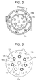
- the discharge chamber 142 in annular shape is concentrically disposed outside the suction chamber 141, as illustrated in FIG. 1 and FIG. 2 .
- the suction chamber 141 is in communication with the cylinder bores 101a via suction holes 103a and suction valves (not shown) formed in a suction valve forming plate.
- the suction holes 103a see FIG. 1 and FIG.
- the suction holes 103a are arranged as illustrated in FIG. 3 . That is, when the valve plate 103 is assembled between the cylinder head 104 and the cylinder block 101, the respective suction holes 103a are spaced from the axis O of the drive shaft 110 in a circumferential direction with approximately equal distance therefrom, and are spaced apart from each other at approximately equal intervals around the drive shaft 110.
- a communication hole 150a which will be described below is formed with its center of opening aligned with the axis O of the drive shaft 110. In other words, the suction holes 103a are spaced apart in a circumferential direction of the communication hole 150a, with approximately equal distance from the center of opening of the communication hole 150a.
- the discharge chamber 142 is in communication with the cylinder bores 101 a via a discharge valve (not shown) formed in the discharge valve forming plate, and via discharge holes 103b formed in the valve plate 103.
- the suction chamber 141 and the discharge chamber 142 are partitioned by a partition wall 104b.
- the partition wall 104b is formed in an approximately circular ring shape about the axis O of the drive shaft 110.
- the suction chamber 141 as a whole has an approximately circular shape.
- FIG. 4 is a partial cross sectional view of the cylinder gasket 138, the valve plate 103, and the head gasket 139.
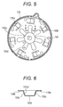
- FIG. 5 is a top plan view of the head gasket 139.
- a suction passage 104a having a connection port 104a' is formed in the cylinder head 104.
- the connection port 104a' is connected to a suction side refrigerant circuit of the aforementioned vehicle air conditioner system.
- refrigerant flows into the suction chamber 141 (a first space portion 141 a which will be described below) from the suction passage 104a.
- the suction passage 104a extends from the outer periphery of the cylinder head 104 into the suction chamber 141 in a straight line, traversing a part of the discharge chamber 142.
- the suction chamber 141 is partitioned by the partition member 150 into the first space portion 141 a connected to the suction passage 104a, and the second space portion 141b connected to the suction holes 103a.
- the communication hole 150a providing communication between the first space portion 141a and the second space portion 141b is formed. The partition member 150 and the communication hole 150a will be described in detail below.
- a suction throttle valve 250 is disposed in the second space portion 141b.
- the suction throttle valve 250 adjusts its opening degree in accordance with a change in flow rate of the refrigerant flowing into the second space portion 141b from the first space portion 141a via the communication hole 150a.
- the suction throttle valve 250 will also be described in detail below.
- the muffler 143 is provided on the outside of the cylinder block 101.
- the muffler 143 includes a tubular wall 101b extending upward from an outer surface of the cylinder block 101, and a lid member 106 with a bottomed tubular shape which is coupled to the tubular wall 101b via a seal member (not shown).
- the discharge port 106a is formed in the lid member 106.
- the discharge port 106a is connected to the discharge side refrigerant circuit of the vehicle air conditioner system.
- a muffler space 143a in the muffler 143 and the discharge chamber 142 are in communication via a communication passage 144.
- the communication passage 144 is formed through the cylinder block 101, the valve plate 103, and the cylinder head 104.
- the muffler space 143a and the communication passage 144 form a discharge passage providing communication between the discharge chamber 142 and the discharge port 106a.
- the muffler 143 forms the muffler space 143a in the discharge passage.
- a check valve 200 for opening or closing the inlet to the muffler 143 is disposed in the muffler 143.
- the check valve 200 is disposed where the communication passage 144 and the muffler space 143a are connected.
- the check valve 200 operates responsive to a pressure difference between the communication passage 144 (upstream side) and the muffler space 143a (downstream side).
- the check valve 200 is opened when the difference (pressure difference) between a pressure Pu in the communication passage 144 (upstream side pressure) and a pressure Pd in the muffler space 143a (downstream side pressure) is greater than a predetermined value SL (Pu - Pd > SL > 0).
- the check valve 200 is closed, for example, when the pressure difference is equal to or less than the predetermined value SL.
- the cylinder head 104 is further fitted with a control valve 300.
- the control valve 300 adjusts the opening degree of a pressure supply passage 145 providing communication between the discharge chamber 142 and the crank chamber 140. In this way, the control valve 300 controls the amount of discharge gas introduced into the crank chamber 140.
- the refrigerant in the crank chamber 140 flows into the suction chamber 141 (second space portion 141b) via a pressure release passage 146 (which will be described below).
- control valve 300 adjusts the amount of discharged refrigerant introduced into the crank chamber 140 to vary the pressure of the crank chamber 140, thereby varying the inclination angle of the swash plate 111, or the stroke of the pistons 136. Therefore, the control valve 300 can variably control the discharge displacement of the variable displacement compressor 100.
- the control valve 300 includes a solenoid. The amount of power flowing in the solenoid is adjusted based on an external signal.
- the control valve 300 variably controls the discharge displacement to give a predetermined pressure of the suction chamber 141 (the first space portion 141a or the second space portion 141b), which is introduced into a pressure sensing chamber of the control valve 300 via the pressure introduction passage 147.
- the control valve 300 may also forcibly open the pressure supply passage 145 by cutting the supply of power to the solenoid.
- the control valve 300 therefore controls the discharge displacement of the variable displacement compressor 100 to be at a minimum.
- the partition member 150 is formed, as will be described below, by a protrusion of the head gasket 139.
- the partition member 150 partitions the suction chamber 141 into the first space portion 141a connected to the suction passage 104a and the second space portion 141b connected to the suction holes 103a.
- the suction chamber 141 is partitioned into the second space portion 141b directly connected to the suction holes 103a, and the first space portion 141a providing a space on the upstream side of the second space portion.
- the second space portion 141b extends radially from the center toward the respective suction holes 103a.
- the second space portion 141b is provided with guide passages 141b1.
- the guide passages 141b1 guide the suction refrigerant flowing out of the suction throttle valve 250.
- the guide passages 141b1 include a bottom wall 150b and side walls 150c.
- the bottom wall 150b is formed as an inclined wall portion with decreasing passage cross sectional area toward the suction holes 103a.
- the communication hole 150a is formed.
- the communication hole 150a is formed, for example, to communicate between the first space portion 141a and the second space portion 141b at the radial center of the suction chamber 141.
- the communication hole 150a is formed such that the center of opening of the communication hole 150a is aligned with the axis O of the drive shaft 110.
- the second space portion 141b is directly connected to the suction holes 103a while being partitioned from the suction passage 104a by the partition member 150.
- the second space portion 141b is substantially a suction chamber.
- the first space portion 141 a directly connected to the suction passage 104a may be regarded as a part of the suction passage.
- the communication hole 150a substantially provides a suction passage outlet.
- the first space portion 141 a is an extension space that functions as a muffler.
- the substantial suction passage outlet (communication hole 150a) can be disposed at the radial center of the suction chamber 141 without being influenced by the position and/or orientation of the suction passage 104a formed in the cylinder head 104.
- a plurality of protrusion portions 104d is provided on a suction chamber forming wall of the cylinder head 104 facing the valve plate 103.
- the protrusion portions 104d press portions of the head gasket 139 corresponding to the peripheral edge portions of the partition member onto the valve plate side.
- the protrusion portions 104d extend from the bottom wall 104c (the suction chamber forming wall) of the cylinder head 104 in such a way as to press regions between the guide passages 141b1.
- the protrusion portions 104d press the valve plate 103 via the head gasket 139 and the discharge valve forming plate.
- the protrusion portions 104d in annular shape are disposed concentrically to the center of the cylinder head 104 at approximately equal intervals (see FIG. 2 and FIG. 4 ).
- the head gasket 139 is disposed between the valve plate 103 and the cylinder head 104.
- the partition member 150 is formed by causing a part of the head gasket 139 facing the suction chamber 141 to protrude into the suction chamber 141.
- the partition member 150 is formed by utilizing the head gasket 139. Therefore, there is no need to add a new component as the partition member 150. There is also no need to separately add a structure for fixing the partition member 150 within the suction chamber 141. As a result, cost increase due to the provision of the partition member 150 can be limited.
- the head gasket 139 is a rubber coated thin plate of metal. The partition member 150 is pressed integrally with the head gasket 139 and then provided with rubber coating.
- the partition member 150 and the head gasket 139 are integrally formed.
- retainers 139a are formed in radially outside regions of the head gasket 139 corresponding to the discharge chamber 142. The retainers 139a restrict the opening degree of the discharge valve.
- the flat portions 139b are pressed by the protrusion portions 104d. In this way, the partition member 150 can be securely retained on the valve plate 103 side, whereby vibration of the partition member 150 can be suppressed.
- a small hole 150d (see FIG. 5 ) is formed in the bottom wall 150b of one of the guide passages 141b1 that is disposed below the axis O of the drive shaft 110 in gravity direction.
- the small hole 150d provides communication between the first space portion 141a and the guide passages 141b1 (namely, the second space portion 141b).
- the small hole 150d is provided to return oil that accumulates below the first space portion 141 a in gravity direction back into the second space portion 141b.
- the pressure release passage 146 provides communication between the crank chamber 140 and the second space portion 141b, which are on the back of the pistons 136, to release the pressure from the inside of the crank chamber.
- the pressure release passage 146 may include a communication passage 101c (see FIG. 1 ) formed in the cylinder block 101 in parallel with the drive shaft 110, a space 101d (see FIG. 1 and FIG. 4 ) formed at the end of the drive shaft 110, a communication hole (not shown) formed in each of the cylinder gasket 138 and the suction valve forming plate, an orifice 103c (see FIG. 1 and FIG. 4 ) formed in the valve plate 103, and a communication hole formed in the discharge valve forming plate.
- the refrigerant in the crank chamber 140 flows into the suction chamber 141 (second space portion 141b) via the pressure release passage 146.
- FIG. 8 a valve body 251 and a compression coil spring 252 which will be described below are not shown.
- the suction throttle valve 250 is an aperture control valve configured to adjust the opening area of a communication portion, penetrating the partition member 150 and providing communication between the first space portion 141a and the second space portion 141b, in accordance with a pressure difference between the first space portion 141a and the second space portion 141b.
- the suction throttle valve 250 increases the opening area as the pressure difference is increased, and decreases the opening area as the pressure difference is decreased.
- the communication portion penetrating the partition member 150 and providing communication between the first space portion and the second space portion refers to a housing 253 including a peripheral wall 253e1, a flange portion 253e2, and a peripheral wall 253e3 which will be described below.
- the suction throttle valve 250 corresponds to "aperture control valve" according to the present invention.
- the suction throttle valve 250 includes a valve body 251, a compression coil spring 252, the housing 253, and a cap 254.
- the valve body 251, the housing 253, and the cap 254 may be made by resin molding.
- the valve body 251 includes a cylindrical peripheral wall, and an end wall closing one end of the peripheral wall.
- the compression coil spring 252 biases the valve body 251.
- One end of the compression coil spring 252 abuts the end wall of the valve body 251, and the other end abuts the cap 254. In this way, the compression coil spring 252 biases the valve body 251 toward a valve seat 253c as will be described below.
- the housing 253 includes the peripheral wall 253e1, the flange portion 253e2 formed on an outer periphery of the peripheral wall 253e1, and the peripheral wall 253e3 extending from one end portion of the peripheral wall 253e1. As previously stated, the housing 253 corresponds to "communication portion" according to the present invention.
- the peripheral wall 253e1 forms a cylindrical valve chamber 253a (see FIG. 7 and FIG. 8 ) housing the valve body 251 and the compression coil spring 252.
- the suction throttle valve 250 includes an inlet opening 253b and a plurality of outlet openings 253d.
- the inlet opening 253b is opened toward the first space portion 141a.
- the outlet openings 253d are opened in a radial direction of the second space portion 141b.
- the inlet opening 253b is formed by opening the end of the housing 253 on the peripheral wall 253e3 side in the direction of the axis O of the drive shaft 110.
- the housing 253 as the communication portion is positioned at the radial center of the suction chamber 141.
- the end of the housing 253 on the peripheral wall 253e3 side is inserted in, and connected to, the communication hole 150a of the partition member 150. In this way, communication is provided between the inlet opening 253b and the first space portion 141a.
- the inlet opening 253b provides communication between the valve chamber 253a and the first space portion 141a.
- the inlet opening 253b is formed with an inner diameter (inner diameter of the peripheral wall 253e3) smaller than an inner diameter of the cylindrical valve chamber 253a (inner diameter of the peripheral wall 253e1), as illustrated in FIG. 7 .
- one end portion of the peripheral wall 253e3 provides a valve seat 253c with which the end wall of the valve body 251 comes into or out of contact.
- the end wall of the valve body 251 by coming into or out of contact with the valve seat 253c, operates to open or close the inlet opening 253b.
- the plurality of outlet openings 253d is formed by opening the outer periphery of the peripheral wall 253e1 of the housing 253.
- the outlet openings 253d communicate between the valve chamber 253a and the second space portion 141b.
- the outlet openings 253d are spaced apart at substantially equal intervals along the outer periphery of the peripheral wall 253e1.
- the number of the outlet openings 253d is, for example, four.
- the first space portion 141a is placed in communication with the second space portion 141b via the communication portion (housing 253).
- the outlet openings 253d provide triangular opening portions, for example, with one of the vertexes of each triangle pointing toward the inlet opening 253b.
- the vertex provides a minimum opening portion 253d1 that is not completely closed by the peripheral wall of the valve body 251 even when the end wall of the valve body 251 abuts the valve seat 253c (see FIG. 7 ).
- the minimum opening portion 253d1 prevents the first space portion 141a and the second space portion 141b from being shut off from each other, thus providing communication therebetween at all times.
- the opening area of the minimum opening portion 253d1 is set to a minimum area such that self-excited vibrations of the valve body 251 itself in a region of a very small flow rate of refrigerant can be suppressed.
- the opening area of the communication portion refers to the area of the outlet openings 253d that is not closed by the peripheral wall of the valve body 251.
- the suction throttle valve 250 adjusts the substantial area of the outlet openings 253d of the housing 253 operating as the communication portion.
- the suction throttle valve 250 includes the minimum opening portion 253d1.
- the suction throttle valve 250 is configured to prevent the opening portion of the communication portion from being completely closed.
- the cap 254 closes an open end portion of the housing 253.
- the cap 254 is securely fitted in the open portion of the housing 253 at the other end of the peripheral wall 253e1.
- the cap 254 closes the open portion of the peripheral wall 253e1 at the other end side thereof.
- a communication hole 254a is formed at the center of the cap 254.
- a communication hole 103d (see FIG. 3 and FIG. 4 ) is formed.
- the communication hole 103d provides communication between a space 152a in a support member 152, which will be described below, and the second space portion 141b. In this way, a space 255 (see FIG.
- a plurality of protrusions 254b (see FIGS. 7 to 9 ) is formed on the cap 254.
- a gap is formed by the protrusions 254b between the other end portion of the suction throttle valve 250 and the support member 152. Therefore, the opening of the communication hole 254a can be prevented or restricted from being shut off by the support member 152. In this way, the pressure of the second space portion 141b can be caused to securely act in the space 255 within the suction throttle valve 250.
- the structure for holding the suction throttle valve 250 will be described.
- a discharge valve forming plate (not shown), the valve plate 103 (see FIG. 3 ), and a suction valve forming plate (not shown)
- through-holes (the through-hole 103e for the valve plate 103) are formed.
- the centers of the respective through-holes are aligned with the communication hole 150a of the partition member 150.
- the through-hole 103e of the valve plate 103 is formed with a diameter slightly larger than the outer diameter of the peripheral wall 253e1.
- the other through-holes are formed with diameters greater than the through-hole 103e of the valve plate 103.
- the suction throttle valve 250 is allowed to be inserted in the through-hole 103e formed in the valve plate 103.
- the through-hole 103e provides a guide for restricting the movement of the suction throttle valve 250 in the radial direction. Therefore, the through-hole 103e facilitates the positioning of the suction throttle valve 250 in the radial direction.
- the through-hole for guiding the suction throttle valve 250 is not limited to the through-hole 103e of the valve plate 103, and may be the through-hole of the discharge valve forming plate or the through-hole of the suction valve forming plate.
- the peripheral wall 253e1 of the suction throttle valve 250 When the peripheral wall 253e1 of the suction throttle valve 250 is inserted in the through-hole (such as 103e), the other end portion (the side of the cap 254) of the suction throttle valve 250 protrudes into the space 101d, as illustrated in FIG. 4 .
- the space 101d provides a recess at the radial center of the cylinder block 101 at one end surface thereof.
- the other end portion (the end on the cap 254 side) of the suction throttle valve 250 is supported by the support member 152 disposed in the space 101d.
- the support member 152 is formed by causing a part of the cylinder gasket 138 facing the space 101d to protrude into the space 101d in a generally truncated conical shape. In this way, the need to add a new component as the support member 152 can be eliminated. Further, the need for a structure for supporting the support member 152 can be eliminated. Thus, cost increase due to the provision of the support member 152 can be limited.
- the cylinder gasket 138 is a rubber coated thin plate of metal. The support member 152 is pressed integrally with the cylinder gasket 138 and then rubber coated.
- the support member 152 provides a partition wall between a region in which the pressure of the crank chamber 140 acts and a region in which the pressure of the suction chamber 141 acts.
- the support member 152 can be stably held in place because its peripheral edges are sandwiched between the cylinder block 101 and the valve plate 103.
- the one end portion (the end on the peripheral wall 253e3 side) of the suction throttle valve 250 is configured to be pressed toward the support member 152 via the peripheral edge portion of the communication hole 150a of the partition member 150.
- the suction throttle valve 250 is disposed in a region on the extension of the axis O of the drive shaft 110.
- the partition member 150 presses the one end portion of the suction throttle valve 250.
- the suction throttle valve 250 is sandwiched between the partition member 150 and the support member 152. In this way, the suction throttle valve can be easily held in place.
- an elastic member 151 is disposed between the one end portion (such as one end surface of the flange portion 253e2) of the suction throttle valve 250 and the partition member 150 at the peripheral edge portion of the communication hole 150a.
- the elastic member 151 may include a circular ring-shaped rubber seat or an O ring. In this way, the suction throttle valve 250 can be easily pressed and held in place.
- the location of the elastic member 151 is not limited between the one end portion of the suction throttle valve 250 and the partition member 150, and may be between the other end portion (the end on the cap 254 side) of the suction throttle valve 250 and the support member 152 (not shown).
- variable displacement compressor 100 When the variable displacement compressor 100 is activated and the pistons 136 are reciprocated, refrigerant is circulated in the refrigerant circuit of the air conditioner system. In accordance with the flow rate of the refrigerant, a pressure difference is produced between the first space portion 141 a and the second space portion 141b.
- the valve body 251 receives the pressure of the first space portion 141a from the inlet opening 253b side, and also receives the pressure of the second space portion 141b from the space 255 side.
- the suction throttle valve 250 operates the valve body 251 responsive to the pressure difference between the first space portion 141 a and the second space portion 141b. In this way, the suction throttle valve 250 adjusts the substantial opening area of the outlet openings 253d of the housing 253 as the communication portion.
- the suction throttle valve 250 increases the substantial opening area of the outlet openings 253d when the flow rate of the refrigerant circulating in the refrigerant circuit is increased such that the pressure difference is increased above the predetermined value. As the flow rate of the refrigerant decreases and the pressure difference is reduced, the suction throttle valve 250 decreases the substantial opening area of the outlet openings 253d. Thus, the suction throttle valve 250 adjusts the substantial opening area of the outlet openings 253d in accordance with a change in refrigerant flow rate. When the refrigerant flow rate becomes very small, and the pressure difference is reduced to equal to or less than the predetermined value, the suction throttle valve 250 decreases the substantial opening area of the outlet openings 253d to the minimum value.
- the suction pressure pulsation on the second space portion 141b side which may be produced particularly when the refrigerant flow rate becomes small, can be restricted from being transmitted to the first space portion 141a side in the suction stroke of the pistons 136. In this way, transmission of pressure pulsation to the external refrigerant circuit side can be restricted. Therefore, vibration of the heat exchanger and the like can be decreased.
- the suction chamber 141 is partitioned by the partition member 150 into the first space portion 141a and the second space portion 141b.
- the suction passage 104a is connected to the first space portion 141a, and the suction holes 103a are connected to the second space portion 141b.
- the opening area of the communication portion (housing 253) penetrating the first space portion 141a and the second space portion 141b is decreased by the suction throttle valve 250 (aperture control valve). In this way, transmission of pressure pulsation to the external refrigerant circuit side can be restricted.
- variable displacement compressor 100 is configured to adjust the opening area of the communication portion (housing 253) penetrating the first space portion 141a and the second space portion 141b, the suction throttle valve 250 can be disposed without being restricted by the position and/or orientation of the suction passage 104a. Therefore, a reciprocating compressor such that the suction throttle valve 250 can be disposed without restrictions by the position and/or orientation of the suction passage can be provided.
- the communication portion (housing 253) is positioned at the radial center of the suction chamber 141.
- the suction holes 103a are formed in the valve plate 103.
- the suction throttle valve 250 (aperture control valve) includes the inlet opening 253b opened toward the first space portion 141a, and the plurality of outlet openings 253d opened in the radial direction of the second space portion 141b.
- the suction holes 103a are spaced apart along the circumferential direction of the communication hole 150a, with approximately equal distance from the center of opening of the communication hole 150a.
- the length of the flow passages from the communication hole 150a i.e., the substantial outlet of the suction passage 104a, to the respective outlet openings 253d and suction holes 103a can be made approximately equal.
- the suction pressure pulsation on the second space portion 141b side can be minimized. This is combined with the effect of tightening the suction throttle valve 250 in a synergistic effect, whereby transmission of pressure pulsation from the first space portion 141a to the external refrigerant circuit side can be effectively restricted.
- the support member 152 is integrally formed with the cylinder gasket 138.
- the support member may be formed separately from the cylinder gasket 138, as according to a second embodiment described below.
- FIG. 10 and FIG. 11 are partially enlarged views of the variable displacement compressor 100 according to the second embodiment of the present invention.
- elements similar to those of the first embodiment will be designated with similar reference signs and their description will be omitted, while focusing on different portions.
- Description of operation of the suction throttle valve 250 will also be omitted as the operation is similar to that in the first embodiment.
- a support member 152' is formed separately from the cylinder gasket 138.
- the support member 152' is formed in a generally truncated conical shape, for example.
- the support member 152' includes a bottom wall 152'a, a peripheral wall 152'b, and a flange 152'c.
- the support member 152' is formed, for example, by pressing a thin plate of metal.
- the support member 152' may be formed of resin material.
- the support member 152' is inserted in a through-hole formed at the radial center of a suction valve forming plate 153 disposed between the cylinder gasket 138 and the valve plate 103. Both the bottom wall 152'a and the peripheral wall 152'b protrude into the space 101d.
- the flange 152'c abuts the suction valve forming plate 153.
- a recess is formed in consideration of the plate thickness of the flange 152'c. In this way, the flange 152'c is positioned between the suction valve forming plate 153 and the valve plate 103 and held therebetween.
- the suction valve forming plate 153 is formed of a plate material having elasticity.
- the depth of the abutting portion of the valve plate 103 is set such that the suction valve forming plate 153 can slightly press the flange 152'c when the flange 152'c is positioned and held between the suction valve forming plate 153 and the valve plate 103.
- the surface of the support member 152' is rubber coated, as is the cylinder gasket 138 and the like.
- the support member 152' can be therefore stably held between the suction valve forming plate 153 and the valve plate 103, leading to further prevent or restrict the leakage of refrigerant from the space 101d (where the pressure of the crank chamber acts) to the second space portion 141b (where the pressure of the suction chamber acts).
- valve plate 103 and a discharge valve forming plate 154 communication holes are formed so that the pressure of the second space portion 141b acts in the space 255 in the suction throttle valve 250.
- the communication holes communicate between the space 152a' in the support member 152' and the second space portion 141b.
- the reader is referred to FIG. 4 .
- the suction throttle valve 250 is inserted in the through-holes formed at the radial center of the valve plate 103 and the discharge valve forming plate 154.
- the protrusions 254b abut the bottom wall 152'a of the support member 152'.
- the partition member 150 presses one end portion of the suction throttle valve 250 via the elastic member 151.
- the suction throttle valve 250 is sandwiched between the partition member 150 and the support member 152'.
- the flange 152'c may be positioned between the discharge valve forming plate 154 (see FIG. 10 ), disposed and held between the head gasket 139 and the valve plate 103, and the valve plate 103, instead of between the suction valve forming plate 153 and the valve plate 103.
- the flange 152'c may be positioned and held between the suction valve forming plate 153 and the discharge valve forming plate 154.
- the partition member 150 is integrally formed with the head gasket 139, but not limited thereto.
- the partition member 150 may be formed separately from the head gasket 139, as will be described below with reference to a third embodiment.
- FIG. 12 is a partially enlarged view of the variable displacement compressor 100 according to the third embodiment of the present invention.
- elements similar to those of the first embodiment will be designated with similar signs with their description omitted, and only different portions will be described.
- Operation of the suction throttle valve 250 is also similar to that according to the first embodiment and its description will be omitted.
- a partition member 150' is formed separately from the head gasket 139.
- the partition member 150' is made of a plate material or the like. As illustrated in FIG. 12 , the partition member 150' fits in a stepped portion 141c formed in the middle of the suction chamber forming wall of the suction chamber 141. The partition member 150' partitions the suction chamber 141 into a first space portion 141 a and a second space portion 141b.
- the one end portion (peripheral wall 253e3 side) of the suction throttle valve 250 abuts the partition member 150'.
- the other end portion (cap 254 side) of the suction throttle valve 250 is completely housed within the second space portion 141b and abuts the head gasket 139.
- the suction throttle valve 250 is configured such that, when the front housing 102, the cylinder block 101, and the cylinder head 104 are fastened by the plurality of through bolts 105, the partition member 150' presses the one end portion of the suction throttle valve 250 via the elastic member 151.
- the suction throttle valve 250 is sandwiched between the partition member 150' and the support member 152" (head gasket 139). In this way, the suction throttle valve can be easily held in place.
- the head gasket 139 also provides the support member 152", but not limited thereto.
- any of the discharge valve forming plate 154, the valve plate 103, the suction valve forming plate 153, and the cylinder gasket 138 may also provide the support member 152".
- a through-hole is provided at the position of the head gasket 139 corresponding to the other end portion of the suction throttle valve 250.
- the other end portion (cap 254 side) of the suction throttle valve 250 is completely housed within the second space portion 141b, but not limited thereto.
- the other end portion (cap 254 side) of the suction throttle valve 250 may protrude into the space 101d of the cylinder block 101, as according to the first and second embodiments.
- the support member 152 of the first embodiment, or the support member 152' of the second embodiment may be applied as the support member.
- the communication hole 150a formed in the partition member 150 is formed at the radial center of the suction chamber 141, but not limited thereto.
- the communication hole 150a may be formed in accordance with the location of the suction throttle valve 250.
- the suction throttle valve 250 is held in place by being sandwiched between the partition member 150 and the support member (152, 152', 152"), but not limited thereto.
- the suction throttle valve 250 may be fixed to the partition member 150.
- the suction throttle valve 250 includes the minimum opening portion 253d1 that is not completely closed by the peripheral wall of the valve body 251. Further, when the valve body 251 is seated on the valve seat 253c, the flow passage in the suction throttle valve 250 is not completely blocked.
- the suction throttle valve 250 may be configured such that the flow passage in the suction throttle valve 250 is completely blocked when the valve body 251 is seated on the valve seat 253c.
- a swash plate type variable displacement compressor has been described as an example of the reciprocating compressor according to the present invention.
- the reciprocating compressor according to the present invention is not limited to the swash plate type, and may be a wobble plate type variable displacement compressor.
- the reciprocating compressor according to the present invention is not limited to variable displacement compressors, and is applicable to all reciprocating compressors.
- the reciprocating compressor according to the present invention may be applied in reciprocating compressors such as a fixed displacement compressor and an electric compressor driven by a motor.
- the reciprocating compressor according to the present invention may be the following first to seventh reciprocating compressors.
- the first reciprocating compressor comprises a suction chamber disposed on one end side of a drive shaft and into which refrigerant flows from a suction passage; a plurality of cylinder bores arranged around the drive shaft; a suction hole corresponding to each of the cylinder bores; and a discharge chamber in annular shape concentrically disposed outside the suction chamber, wherein pistons in the cylinder bores are reciprocated by rotation of the drive shaft so as to compress the refrigerant suctioned into the cylinder bores from the suction chamber via the suction hole, and wherein the compressed refrigerant is discharged via the discharge chamber, the reciprocating compressor including a partition member partitioning the suction chamber into a first space portion connected to the suction passage and a second space portion connected to the suction hole, and an aperture control valve adjusting the area of an opening of a communication portion penetrating the partition member and providing communication between the first space portion and the second space
- the second reciprocating compressor is the first reciprocating compressor wherein the communication portion is positioned at a radial center of the suction chamber, and wherein the suction holes are formed in a valve plate abutting a suction chamber side surface of a cylinder head that forms the suction chamber, the aperture control valve including an inlet opening opened toward the first space portion, and a plurality of outlet openings opened in a radial direction of the second space portion.
- the third reciprocating compressor is the second reciprocating compressor wherein the valve plate includes a through-hole in which the aperture control valve is inserted, restricting radial movement of the aperture control valve.
- the fourth reciprocating compressor is the second or the third reciprocating compressor and is characterized in that the partition member is formed by a part of a head gasket disposed between the valve plate and the cylinder head, the part facing and protruding into the suction chamber.
- the fifth reciprocating compressor is the fourth reciprocating compressor characterized in that the cylinder head includes a suction chamber forming wall facing the valve plate and having a protrusion portion pressing a peripheral edge portion of the partition member part of the head gasket toward the valve plate.
- the sixth reciprocating compressor is one of the first to fifth reciprocating compressors wherein the aperture control valve is supported on one end portion thereof by a support member, with another end portion of the aperture control valve being pressed by the partition member toward the support member.
- the seventh reciprocating compressor is the sixth reciprocating compressor characterized by an elastic member disposed between the one end portion of the aperture control valve and the support member, or between the other end portion of the aperture control valve and the partition member.
Landscapes
- Engineering & Computer Science (AREA)
- Mechanical Engineering (AREA)
- General Engineering & Computer Science (AREA)
- Manufacturing & Machinery (AREA)
- Compressors, Vaccum Pumps And Other Relevant Systems (AREA)
- Compressor (AREA)
Abstract
Description
- The present invention relates to reciprocating compressors.
- Reciprocating compressors compress refrigerant by reciprocatively moving a piston. Some of the reciprocating compressors are equipped with a refrigerant suction throttle valve (an aperture control valve). In a reciprocating compressor used in a conventional vehicle air conditioner system or the like, a connection port for external refrigerant circuit and a suction chamber are in communication with each other via a suction passage. The suction passage allows the refrigerant to flow into the suction chamber. Then, the reciprocating motion of the piston allows the refrigerant to be suctioned from the suction chamber via a suction hole, and then compresses and discharges the suctioned refrigerant. A suction valve disposed at a position corresponding to the suction hole is known to cause self-excited vibration, particularly when the flow rate of the refrigerant is small. Such vibration or the like may produce pressure pulsation. Then, transmission of the pressure pulsation may occur via connection piping connecting the suction chamber, the suction passage, the connection port, and the external refrigerant circuit to one another, thereby causing vibration of a heat exchanger and the like in the external refrigerant circuit.
- Thus, the reciprocating compressor described in
JP-A-2011-32878 - However, in the reciprocating compressor described in
JP-A-2011-32878 - The present invention has been made in consideration of the above problem, and an object of the present invention is to provide a reciprocating compressor in which an aperture control valve can be installed without being restricted by the position and/or orientation of a suction passage.
- To achieve the object, a reciprocating compressor of a first embodiment of the present invention, includes: a suction chamber disposed on one end side of a drive shaft and into which a refrigerant flows from a suction passage; a plurality of cylinder bores arranged around the drive shaft; a suction hole corresponding to each of the cylinder bores; and a discharge chamber in annular shape concentrically disposed outside the suction chamber. Pistons in the cylinder bores are reciprocated by rotation of the drive shaft to compress the refrigerant suctioned into the cylinder bores from the suction chamber via the suction hole and discharge the compressed refrigerant via the discharge chamber. the reciprocating compressor includes: a partition member partitioning the suction chamber into a first space portion connected to the suction passage and a second space portion connected to the suction hole, and an aperture control valve that adjusts the area of an opening of a communication portion penetrating the partition member and providing communication between the first space portion and the second space portion, the aperture control valve being configured to increase the opening area as a pressure difference between the first space portion and the second space portion is increased and to decrease the opening area as the pressure difference is decreased.
- In the reciprocating compressor according to the embodiment of the present invention, the suction chamber is partitioned by the partition member into the first space portion and the second space portion. The suction passage is connected to the first space portion, and the suction hole is connected to the second space portion. The communication portion penetrates the first space portion and the second space portion. The aperture control valve decreases the opening area of the communication portion as the pressure difference between the first space portion and the second space portion is decreased. In this way, transmission of pressure pulsation to the external refrigerant circuit side can be restricted. Thus, the reciprocating compressor according to the embodiment of the present invention can adjust the opening area of the communication portion penetrating the first space portion and the second space portion. Therefore, a reciprocating compressor can be provided such that an aperture control valve can be disposed without restrictions due to the position and/or orientation of the suction passage.
-
-
FIG. 1 is a cross sectional view of a reciprocating compressor according to a first embodiment of the present invention; -
FIG. 2 is a view of a cylinder head in the embodiment as viewed from the valve plate side; -
FIG. 3 is a top view of a valve plate in the embodiment; -
FIG. 4 is a partially enlarged view ofFIG. 1 ; -
FIG. 5 is a top view of a head gasket and a partition member in the embodiment; -
FIG. 6 is a partial cross sectional view taken along A-A ofFIG. 4 ; -
FIG. 7 is an enlarged cross sectional view of a suction throttle valve in the embodiment, seated on a valve seat of a valve body; -
FIG. 8 is an enlarged cross sectional view of the suction throttle valve in the embodiment, omitting illustration of the valve body and a compression coil spring; -
FIG. 9 is a side view of the suction throttle valve as viewed from arrow direction B inFIG. 7 ; -
FIG. 10 is a partial cross sectional view of the reciprocating compressor according to a second embodiment of the present invention; -
FIG. 11 is a cross sectional view of a support member illustrated inFIG. 10 ; and -
FIG. 12 is a partial cross sectional view of the reciprocating compressor according to a third embodiment of the present invention. - In the following detailed description, for purpose of explanation, numerous specific details are set forth in order to provide a thorough understanding of the disclosed embodiments. It will be apparent, however, that one or more embodiments may be practiced without these specific details. In other instances, well-known structures and devices are schematically shown in order to simplify the drawing.
- In the following, embodiments of the present invention will be described with reference to the attached drawings.
FIG. 1 is a cross sectional view of a swash plate typevariable displacement compressor 100 as an example of a reciprocating compressor to which the present invention is applied. Thevariable displacement compressor 100 is connected to an external refrigerant circuit (not shown). Thevariable displacement compressor 100 compresses and discharges a refrigerant, suctioned from the external refrigerant circuit, by reciprocating a plurality ofpistons 136. According to the present embodiment, thevariable displacement compressor 100 is envisioned to be used in a vehicle air conditioner system. - As illustrated in
FIG. 1 , thevariable displacement compressor 100 includes acylinder block 101, afront housing 102, and acylinder head 104. In thecylinder block 101,cylinder bores 101a in which thepistons 136 are disposed are formed. Thefront housing 102 is provided at one end of thecylinder block 101. Thecylinder head 104 is provided at the other end of thecylinder block 101 via avalve plate 103 and the like. - The
cylinder block 101 and thefront housing 102 form acrank chamber 140 to the back of thepistons 136. Adrive shaft 110 is provided traversing thecrank chamber 140. Thedrive shaft 110 is rotatably supported by thecylinder block 101 and thefront housing 102. In thecylinder block 101, thecylinder bores 101a are arranged around thedrive shaft 110. - Around an intermediate portion of the
drive shaft 110 in an axial direction thereof, aswash plate 111 is disposed. At the center of theswash plate 111, a through-hole 111b is formed. Thedrive shaft 110 is inserted in the through-hole 111b. Arotor 112 is fixed to thedrive shaft 110. Theswash plate 111 is coupled via alink mechanism 120 to therotor 112 that integrally rotates with thedrive shaft 110. Thelink mechanism 120 enables theswash plate 111 to rotate with thedrive shaft 110 and therotor 112, and also enables the inclination angle of theswash plate 111 to be varied with respect to the axis of thedrive shaft 110. - The
link mechanism 120 includes afirst arm 112a protruding from therotor 112, asecond arm 111a protruding from theswash plate 111, and alink arm 121. One end of thelink arm 121 is rotatably coupled via afirst coupling pin 122 to thefirst arm 112a. The other end of thelink arm 121 is rotatably coupled via asecond coupling pin 123 to thesecond arm 111a. - The through-
hole 111b of theswash plate 111 is formed in a shape allowing theswash plate 111 to be inclined in a range from a maximum inclination angle to a minimum inclination angle. According to the present embodiment, in the through-hole 111b, a minimum inclination angle-restricting portion is formed. The minimum inclination angle-restricting portion abuts thedrive shaft 110, thereby restricting the inclination angle displacement (tilting) of theswash plate 111 in a direction of decreasing inclination angle. For example, the inclination angle of theswash plate 111 is zero when theswash plate 111 is perpendicular to thedrive shaft 110. In this case, the minimum inclination angle-restricting portion is formed such that the inclination angle displacement (tilting) of theswash plate 111 is permitted until the inclination angle of theswash plate 111 becomes effectively zero. The inclination angle displacement (tilting) of theswash plate 111 in a direction of increasing inclination angle is restricted by theswash plate 111 abutting therotor 112. Thus, the inclination angle of theswash plate 111 is at the maximum inclination angle when theswash plate 111 abuts therotor 112. - On the
drive shaft 110, an inclinationangle reducing spring 114 and an inclinationangle increasing spring 115 are attached across theswash plate 111. The inclinationangle reducing spring 114 biases theswash plate 111 in the direction of decreasing inclination angle. The inclinationangle increasing spring 115 biases theswash plate 111 in the direction of increasing inclination angle. Specifically, the inclinationangle reducing spring 114 is mounted between theswash plate 111 and therotor 112. The inclinationangle increasing spring 115 is mounted between theswash plate 111 and aspring support member 116 provided on thedrive shaft 110. - The biasing forces of the inclination
angle increasing spring 115 and the inclinationangle reducing spring 114 are set such that, when the inclination angle of theswash plate 111 is the minimum inclination angle, the biasing force of the inclinationangle increasing spring 115 is greater than the biasing force of the inclinationangle reducing spring 114. Thus, when thedrive shaft 110 is not rotating; namely, when thevariable displacement compressor 100 is stopped, the inclination angle of theswash plate 111 is an inclination angle (> minimum inclination angle) such that the biasing force of the inclinationangle reducing spring 114 and the biasing force of the inclinationangle increasing spring 115 balance each other out. - One end of the
drive shaft 110 penetrates aboss portion 102a of thefront housing 102 and extends externally of thefront housing 102, and is coupled to a power transmission apparatus (not shown). Between thedrive shaft 110 and theboss portion 102a, ashaft seal device 130 is inserted. Thus, the inside of thecrank chamber 140 is shielded from the external space. - The coupled assembly of the
drive shaft 110 and therotor 112 is supported byradial bearings thrust bearing 133 and athrust plate 134 in the thrust direction. The end of thedrive shaft 110 on thethrust plate 134 side and thethrust plate 134 are adjusted to have a predetermined gap by an adjustscrew 135. Thedrive shaft 110 is rotated in synchronism with the power transmission apparatus as power from the external drive source, (not shown), is transmitted to the power transmission apparatus. - In the cylinder bores 101a, the
pistons 136 are disposed. In a space inside of an end portion of thepistons 136 that is protruding into thecrank chamber 140, an outer peripheral portion of theswash plate 111 is housed. Theswash plate 111 is configured to cooperate with thepistons 136 via a pair ofshoes 137. Theshoes 137 convert the rotating motion of theswash plate 111 into a reciprocating motion of thepistons 136. Thus, thepistons 136 are reciprocated within the cylinder bores 101a. - In the
cylinder head 104, asuction chamber 141 and adischarge chamber 142 are separately formed. Thesuction chamber 141 is disposed at one end side of the drive shaft 110 (specifically, on the extension of an axis O). Thedischarge chamber 142 in annular shape is concentrically disposed outside thesuction chamber 141, as illustrated inFIG. 1 andFIG. 2 . Specifically, thesuction chamber 141 is in communication with thecylinder bores 101a viasuction holes 103a and suction valves (not shown) formed in a suction valve forming plate. The suction holes 103a (seeFIG. 1 andFIG. 3 ) are formed in avalve plate 103 abutting a suction chamber side surface of the cylinder head 104 (that is, disposed between thecylinder head 104 and the cylinder block 101), each corresponding to the respective cylinder bores 101 a. Thus, when the pistons are reciprocated by rotation of thedrive shaft 110, the refrigerant suctioned from thesuction chamber 141 via thesuction holes 103a and the like into the cylinder bores 101a is compressed therein. The compressed refrigerant is discharged into a discharge side refrigerant circuit via thedischarge chamber 142 as well as amuffler 143 and adischarge port 106a which will be described below. - According to the present embodiment, the
suction holes 103a are arranged as illustrated inFIG. 3 . That is, when thevalve plate 103 is assembled between thecylinder head 104 and thecylinder block 101, therespective suction holes 103a are spaced from the axis O of thedrive shaft 110 in a circumferential direction with approximately equal distance therefrom, and are spaced apart from each other at approximately equal intervals around thedrive shaft 110. Acommunication hole 150a which will be described below is formed with its center of opening aligned with the axis O of thedrive shaft 110. In other words, thesuction holes 103a are spaced apart in a circumferential direction of thecommunication hole 150a, with approximately equal distance from the center of opening of thecommunication hole 150a. - The
discharge chamber 142 is in communication with the cylinder bores 101 a via a discharge valve (not shown) formed in the discharge valve forming plate, and via discharge holes 103b formed in thevalve plate 103. Thesuction chamber 141 and thedischarge chamber 142 are partitioned by apartition wall 104b. Thepartition wall 104b is formed in an approximately circular ring shape about the axis O of thedrive shaft 110. Thesuction chamber 141 as a whole has an approximately circular shape. - The
front housing 102, a center gasket (not shown), thecylinder block 101, acylinder gasket 138, the suction valve forming plate (not shown), thevalve plate 103, the discharge valve forming plate (not shown), ahead gasket 139, and thecylinder head 104 are fastened by a plurality of throughbolts 105, forming a housing.FIG. 4 is a partial cross sectional view of thecylinder gasket 138, thevalve plate 103, and thehead gasket 139.FIG. 5 is a top plan view of thehead gasket 139. - In the
cylinder head 104, asuction passage 104a having aconnection port 104a' is formed. Theconnection port 104a' is connected to a suction side refrigerant circuit of the aforementioned vehicle air conditioner system. Thus, refrigerant flows into the suction chamber 141 (afirst space portion 141 a which will be described below) from thesuction passage 104a. Thesuction passage 104a extends from the outer periphery of thecylinder head 104 into thesuction chamber 141 in a straight line, traversing a part of thedischarge chamber 142. - The
suction chamber 141 is partitioned by thepartition member 150 into thefirst space portion 141 a connected to thesuction passage 104a, and thesecond space portion 141b connected to thesuction holes 103a. In thepartition member 150, thecommunication hole 150a providing communication between thefirst space portion 141a and thesecond space portion 141b is formed. Thepartition member 150 and thecommunication hole 150a will be described in detail below. - In the
second space portion 141b, asuction throttle valve 250 is disposed. Thesuction throttle valve 250 adjusts its opening degree in accordance with a change in flow rate of the refrigerant flowing into thesecond space portion 141b from thefirst space portion 141a via thecommunication hole 150a. Thesuction throttle valve 250 will also be described in detail below. - As illustrated in
FIG. 1 , themuffler 143 is provided on the outside of thecylinder block 101. Themuffler 143 includes atubular wall 101b extending upward from an outer surface of thecylinder block 101, and alid member 106 with a bottomed tubular shape which is coupled to thetubular wall 101b via a seal member (not shown). In thelid member 106, thedischarge port 106a is formed. Thedischarge port 106a is connected to the discharge side refrigerant circuit of the vehicle air conditioner system. Amuffler space 143a in themuffler 143 and thedischarge chamber 142 are in communication via acommunication passage 144. Thecommunication passage 144 is formed through thecylinder block 101, thevalve plate 103, and thecylinder head 104. Themuffler space 143a and thecommunication passage 144 form a discharge passage providing communication between thedischarge chamber 142 and thedischarge port 106a. Themuffler 143 forms themuffler space 143a in the discharge passage. - A
check valve 200 for opening or closing the inlet to themuffler 143 is disposed in themuffler 143. Thecheck valve 200 is disposed where thecommunication passage 144 and themuffler space 143a are connected. Thecheck valve 200 operates responsive to a pressure difference between the communication passage 144 (upstream side) and themuffler space 143a (downstream side). For example, thecheck valve 200 is opened when the difference (pressure difference) between a pressure Pu in the communication passage 144 (upstream side pressure) and a pressure Pd in themuffler space 143a (downstream side pressure) is greater than a predetermined value SL (Pu - Pd > SL > 0). Thecheck valve 200 is closed, for example, when the pressure difference is equal to or less than the predetermined value SL. - The
cylinder head 104 is further fitted with acontrol valve 300. Thecontrol valve 300 adjusts the opening degree of apressure supply passage 145 providing communication between thedischarge chamber 142 and thecrank chamber 140. In this way, thecontrol valve 300 controls the amount of discharge gas introduced into thecrank chamber 140. The refrigerant in thecrank chamber 140 flows into the suction chamber 141 (second space portion 141b) via a pressure release passage 146 (which will be described below). - Hence, the
control valve 300 adjusts the amount of discharged refrigerant introduced into thecrank chamber 140 to vary the pressure of thecrank chamber 140, thereby varying the inclination angle of theswash plate 111, or the stroke of thepistons 136. Therefore, thecontrol valve 300 can variably control the discharge displacement of thevariable displacement compressor 100. - The
control valve 300 includes a solenoid. The amount of power flowing in the solenoid is adjusted based on an external signal. Thecontrol valve 300 variably controls the discharge displacement to give a predetermined pressure of the suction chamber 141 (thefirst space portion 141a or thesecond space portion 141b), which is introduced into a pressure sensing chamber of thecontrol valve 300 via thepressure introduction passage 147. Thecontrol valve 300 may also forcibly open thepressure supply passage 145 by cutting the supply of power to the solenoid. Thecontrol valve 300 therefore controls the discharge displacement of thevariable displacement compressor 100 to be at a minimum. - In the following, referring to
FIGS. 2 to 6 , thepartition member 150, thecommunication hole 150a, and thepressure release passage 146 among others will be described in detail. - The
partition member 150 is formed, as will be described below, by a protrusion of thehead gasket 139. In addition, as described above, thepartition member 150 partitions thesuction chamber 141 into thefirst space portion 141a connected to thesuction passage 104a and thesecond space portion 141b connected to thesuction holes 103a. Thus, thesuction chamber 141 is partitioned into thesecond space portion 141b directly connected to thesuction holes 103a, and thefirst space portion 141a providing a space on the upstream side of the second space portion. - As illustrated in
FIG. 4 andFIG. 5 , thesecond space portion 141b extends radially from the center toward therespective suction holes 103a. Thesecond space portion 141b is provided with guide passages 141b1. The guide passages 141b1 guide the suction refrigerant flowing out of thesuction throttle valve 250. As illustrated inFIG. 6 , the guide passages 141b1 include abottom wall 150b andside walls 150c. As illustrated inFIG. 4 , thebottom wall 150b is formed as an inclined wall portion with decreasing passage cross sectional area toward thesuction holes 103a. - In the
partition member 150, thecommunication hole 150a is formed. Thecommunication hole 150a is formed, for example, to communicate between thefirst space portion 141a and thesecond space portion 141b at the radial center of thesuction chamber 141. Specifically, thecommunication hole 150a is formed such that the center of opening of thecommunication hole 150a is aligned with the axis O of thedrive shaft 110. - As described herein, the
second space portion 141b is directly connected to thesuction holes 103a while being partitioned from thesuction passage 104a by thepartition member 150. Thus, thesecond space portion 141b is substantially a suction chamber. Thefirst space portion 141 a directly connected to thesuction passage 104a may be regarded as a part of the suction passage. Thecommunication hole 150a substantially provides a suction passage outlet. Thefirst space portion 141 a is an extension space that functions as a muffler. In this configuration, the substantial suction passage outlet (communication hole 150a) can be disposed at the radial center of thesuction chamber 141 without being influenced by the position and/or orientation of thesuction passage 104a formed in thecylinder head 104. - On a suction chamber forming wall of the
cylinder head 104 facing thevalve plate 103, a plurality ofprotrusion portions 104d is provided. Theprotrusion portions 104d press portions of thehead gasket 139 corresponding to the peripheral edge portions of the partition member onto the valve plate side. Specifically, theprotrusion portions 104d extend from thebottom wall 104c (the suction chamber forming wall) of thecylinder head 104 in such a way as to press regions between the guide passages 141b1. Theprotrusion portions 104d press thevalve plate 103 via thehead gasket 139 and the discharge valve forming plate. Theprotrusion portions 104d in annular shape are disposed concentrically to the center of thecylinder head 104 at approximately equal intervals (seeFIG. 2 andFIG. 4 ). - The
head gasket 139 is disposed between thevalve plate 103 and thecylinder head 104. For example, thepartition member 150 is formed by causing a part of thehead gasket 139 facing thesuction chamber 141 to protrude into thesuction chamber 141. Thus, thepartition member 150 is formed by utilizing thehead gasket 139. Therefore, there is no need to add a new component as thepartition member 150. There is also no need to separately add a structure for fixing thepartition member 150 within thesuction chamber 141. As a result, cost increase due to the provision of thepartition member 150 can be limited. Thehead gasket 139 is a rubber coated thin plate of metal. Thepartition member 150 is pressed integrally with thehead gasket 139 and then provided with rubber coating. That is, thepartition member 150 and thehead gasket 139 are integrally formed. In radially outside regions of thehead gasket 139 corresponding to thedischarge chamber 142,retainers 139a (seeFIG. 5 ) are formed. Theretainers 139a restrict the opening degree of the discharge valve. - Both sides of the
side walls 150c where the guide passages 141b1 of thepartition member 150 are formed, provided areflat portions 139b (seeFIG. 6 ) of thehead gasket 139. Theflat portions 139b are pressed by theprotrusion portions 104d. In this way, thepartition member 150 can be securely retained on thevalve plate 103 side, whereby vibration of thepartition member 150 can be suppressed. - In the
bottom wall 150b of one of the guide passages 141b1 that is disposed below the axis O of thedrive shaft 110 in gravity direction, a small hole 150d (seeFIG. 5 ) is formed. The small hole 150d provides communication between thefirst space portion 141a and the guide passages 141b1 (namely, thesecond space portion 141b). The small hole 150d is provided to return oil that accumulates below thefirst space portion 141 a in gravity direction back into thesecond space portion 141b. - The
pressure release passage 146 provides communication between thecrank chamber 140 and thesecond space portion 141b, which are on the back of thepistons 136, to release the pressure from the inside of the crank chamber. For example, thepressure release passage 146 may include acommunication passage 101c (seeFIG. 1 ) formed in thecylinder block 101 in parallel with thedrive shaft 110, aspace 101d (seeFIG. 1 andFIG. 4 ) formed at the end of thedrive shaft 110, a communication hole (not shown) formed in each of thecylinder gasket 138 and the suction valve forming plate, anorifice 103c (seeFIG. 1 andFIG. 4 ) formed in thevalve plate 103, and a communication hole formed in the discharge valve forming plate. The refrigerant in thecrank chamber 140 flows into the suction chamber 141 (second space portion 141b) via thepressure release passage 146. - Referring now to
FIG. 1 ,FIG. 4 , andFIGS. 7 to 9 , the structure of thesuction throttle valve 250 and a method of retaining it will be described in detail. InFIG. 8 , avalve body 251 and acompression coil spring 252 which will be described below are not shown. - The
suction throttle valve 250 is an aperture control valve configured to adjust the opening area of a communication portion, penetrating thepartition member 150 and providing communication between thefirst space portion 141a and thesecond space portion 141b, in accordance with a pressure difference between thefirst space portion 141a and thesecond space portion 141b. Thesuction throttle valve 250 increases the opening area as the pressure difference is increased, and decreases the opening area as the pressure difference is decreased. According to the present embodiment, the communication portion penetrating thepartition member 150 and providing communication between the first space portion and the second space portion refers to ahousing 253 including a peripheral wall 253e1, a flange portion 253e2, and a peripheral wall 253e3 which will be described below. Thesuction throttle valve 250 corresponds to "aperture control valve" according to the present invention. - The structure of the
suction throttle valve 250 will be described. Specifically, thesuction throttle valve 250 includes avalve body 251, acompression coil spring 252, thehousing 253, and acap 254. Thevalve body 251, thehousing 253, and thecap 254 may be made by resin molding. - The
valve body 251 includes a cylindrical peripheral wall, and an end wall closing one end of the peripheral wall. - The
compression coil spring 252 biases thevalve body 251. One end of thecompression coil spring 252 abuts the end wall of thevalve body 251, and the other end abuts thecap 254. In this way, thecompression coil spring 252 biases thevalve body 251 toward avalve seat 253c as will be described below. - The
housing 253 includes the peripheral wall 253e1, the flange portion 253e2 formed on an outer periphery of the peripheral wall 253e1, and the peripheral wall 253e3 extending from one end portion of the peripheral wall 253e1. As previously stated, thehousing 253 corresponds to "communication portion" according to the present invention. - The peripheral wall 253e1 forms a
cylindrical valve chamber 253a (seeFIG. 7 and FIG. 8 ) housing thevalve body 251 and thecompression coil spring 252. Thesuction throttle valve 250 includes aninlet opening 253b and a plurality ofoutlet openings 253d. Theinlet opening 253b is opened toward thefirst space portion 141a. Theoutlet openings 253d are opened in a radial direction of thesecond space portion 141b. - Specifically, the
inlet opening 253b is formed by opening the end of thehousing 253 on the peripheral wall 253e3 side in the direction of the axis O of thedrive shaft 110. Thehousing 253 as the communication portion is positioned at the radial center of thesuction chamber 141. Specifically, as illustrated inFIG. 4 , the end of thehousing 253 on the peripheral wall 253e3 side is inserted in, and connected to, thecommunication hole 150a of thepartition member 150. In this way, communication is provided between theinlet opening 253b and thefirst space portion 141a. Theinlet opening 253b provides communication between thevalve chamber 253a and thefirst space portion 141a. Theinlet opening 253b is formed with an inner diameter (inner diameter of the peripheral wall 253e3) smaller than an inner diameter of thecylindrical valve chamber 253a (inner diameter of the peripheral wall 253e1), as illustrated inFIG. 7 . Thus, as illustrated inFIG. 7 and FIG. 8 , one end portion of the peripheral wall 253e3 provides avalve seat 253c with which the end wall of thevalve body 251 comes into or out of contact. The end wall of thevalve body 251, by coming into or out of contact with thevalve seat 253c, operates to open or close theinlet opening 253b. - Specifically, the plurality of
outlet openings 253d is formed by opening the outer periphery of the peripheral wall 253e1 of thehousing 253. Theoutlet openings 253d communicate between thevalve chamber 253a and thesecond space portion 141b. Theoutlet openings 253d are spaced apart at substantially equal intervals along the outer periphery of the peripheral wall 253e1. The number of theoutlet openings 253d is, for example, four. Thus, thefirst space portion 141a is placed in communication with thesecond space portion 141b via the communication portion (housing 253). - As illustrated in
FIG. 8 andFIG. 9 , theoutlet openings 253d provide triangular opening portions, for example, with one of the vertexes of each triangle pointing toward theinlet opening 253b. The vertex provides a minimum opening portion 253d1 that is not completely closed by the peripheral wall of thevalve body 251 even when the end wall of thevalve body 251 abuts thevalve seat 253c (seeFIG. 7 ). The minimum opening portion 253d1 prevents thefirst space portion 141a and thesecond space portion 141b from being shut off from each other, thus providing communication therebetween at all times. The opening area of the minimum opening portion 253d1 is set to a minimum area such that self-excited vibrations of thevalve body 251 itself in a region of a very small flow rate of refrigerant can be suppressed. The opening area of the communication portion according to the present embodiment refers to the area of theoutlet openings 253d that is not closed by the peripheral wall of thevalve body 251. Thus, in the present embodiment, thesuction throttle valve 250 adjusts the substantial area of theoutlet openings 253d of thehousing 253 operating as the communication portion. Further, thesuction throttle valve 250 includes the minimum opening portion 253d1. Thus, thesuction throttle valve 250 is configured to prevent the opening portion of the communication portion from being completely closed. - The
cap 254 closes an open end portion of thehousing 253. Thecap 254 is securely fitted in the open portion of thehousing 253 at the other end of the peripheral wall 253e1. Thus, thecap 254 closes the open portion of the peripheral wall 253e1 at the other end side thereof. At the center of thecap 254, acommunication hole 254a is formed. In thevalve plate 103, acommunication hole 103d (seeFIG. 3 andFIG. 4 ) is formed. Thecommunication hole 103d provides communication between aspace 152a in asupport member 152, which will be described below, and thesecond space portion 141b. In this way, a space 255 (seeFIG. 7 ) partitioned by thevalve body 251, the peripheral wall 253e1 of thehousing 253, and thecap 254 is placed in communication with thesecond space portion 141b via thecommunication hole 254a, thespace 152a, and thecommunication hole 103d of thevalve plate 103. As a result, the pressure of thesecond space portion 141b acts in thespace 255. - On the
cap 254, a plurality ofprotrusions 254b (seeFIGS. 7 to 9 ) is formed. Thus, even when the other end portion of thesuction throttle valve 250 abuts thesupport member 152, a gap is formed by theprotrusions 254b between the other end portion of thesuction throttle valve 250 and thesupport member 152. Therefore, the opening of thecommunication hole 254a can be prevented or restricted from being shut off by thesupport member 152. In this way, the pressure of thesecond space portion 141b can be caused to securely act in thespace 255 within thesuction throttle valve 250. - Next, the structure for holding the
suction throttle valve 250 will be described. At the radial center of a discharge valve forming plate (not shown), the valve plate 103 (seeFIG. 3 ), and a suction valve forming plate (not shown), through-holes (the through-hole 103e for the valve plate 103) are formed. The centers of the respective through-holes are aligned with thecommunication hole 150a of thepartition member 150. According to the present embodiment, the through-hole 103e of thevalve plate 103 is formed with a diameter slightly larger than the outer diameter of the peripheral wall 253e1. The other through-holes are formed with diameters greater than the through-hole 103e of thevalve plate 103. Thus, thesuction throttle valve 250 is allowed to be inserted in the through-hole 103e formed in thevalve plate 103. In this way, the through-hole 103e provides a guide for restricting the movement of thesuction throttle valve 250 in the radial direction. Therefore, the through-hole 103e facilitates the positioning of thesuction throttle valve 250 in the radial direction. The through-hole for guiding thesuction throttle valve 250 is not limited to the through-hole 103e of thevalve plate 103, and may be the through-hole of the discharge valve forming plate or the through-hole of the suction valve forming plate. - When the peripheral wall 253e1 of the
suction throttle valve 250 is inserted in the through-hole (such as 103e), the other end portion (the side of the cap 254) of thesuction throttle valve 250 protrudes into thespace 101d, as illustrated inFIG. 4 . Thespace 101d provides a recess at the radial center of thecylinder block 101 at one end surface thereof. - The other end portion (the end on the
cap 254 side) of thesuction throttle valve 250 is supported by thesupport member 152 disposed in thespace 101d. For example, thesupport member 152 is formed by causing a part of thecylinder gasket 138 facing thespace 101d to protrude into thespace 101d in a generally truncated conical shape. In this way, the need to add a new component as thesupport member 152 can be eliminated. Further, the need for a structure for supporting thesupport member 152 can be eliminated. Thus, cost increase due to the provision of thesupport member 152 can be limited. Thecylinder gasket 138 is a rubber coated thin plate of metal. Thesupport member 152 is pressed integrally with thecylinder gasket 138 and then rubber coated. Thesupport member 152 provides a partition wall between a region in which the pressure of thecrank chamber 140 acts and a region in which the pressure of thesuction chamber 141 acts. Thesupport member 152 can be stably held in place because its peripheral edges are sandwiched between thecylinder block 101 and thevalve plate 103. - The one end portion (the end on the peripheral wall 253e3 side) of the
suction throttle valve 250 is configured to be pressed toward thesupport member 152 via the peripheral edge portion of thecommunication hole 150a of thepartition member 150. Thus, thesuction throttle valve 250 is disposed in a region on the extension of the axis O of thedrive shaft 110. When the compressor housing is formed by fastening thefront housing 102, thecylinder block 101, and thecylinder head 104 together by the plurality of throughbolts 105, thepartition member 150 presses the one end portion of thesuction throttle valve 250. At the same time, thesuction throttle valve 250 is sandwiched between thepartition member 150 and thesupport member 152. In this way, the suction throttle valve can be easily held in place. - Specifically, between the one end portion (such as one end surface of the flange portion 253e2) of the
suction throttle valve 250 and thepartition member 150 at the peripheral edge portion of thecommunication hole 150a, anelastic member 151 is disposed. Thus, the one end surface of thesuction throttle valve 250 is elastically supported by thepartition member 150. Theelastic member 151 may include a circular ring-shaped rubber seat or an O ring. In this way, thesuction throttle valve 250 can be easily pressed and held in place. The location of theelastic member 151 is not limited between the one end portion of thesuction throttle valve 250 and thepartition member 150, and may be between the other end portion (the end on thecap 254 side) of thesuction throttle valve 250 and the support member 152 (not shown). - Operation of the
suction throttle valve 250 in thevariable displacement compressor 100 configured as described above will be described with reference toFIGS. 4 to 7 . - When the
variable displacement compressor 100 is activated and thepistons 136 are reciprocated, refrigerant is circulated in the refrigerant circuit of the air conditioner system. In accordance with the flow rate of the refrigerant, a pressure difference is produced between thefirst space portion 141 a and thesecond space portion 141b. Thevalve body 251 receives the pressure of thefirst space portion 141a from the inlet opening 253b side, and also receives the pressure of thesecond space portion 141b from thespace 255 side. Thus, thesuction throttle valve 250 operates thevalve body 251 responsive to the pressure difference between thefirst space portion 141 a and thesecond space portion 141b. In this way, thesuction throttle valve 250 adjusts the substantial opening area of theoutlet openings 253d of thehousing 253 as the communication portion. - Specifically, the
suction throttle valve 250 increases the substantial opening area of theoutlet openings 253d when the flow rate of the refrigerant circulating in the refrigerant circuit is increased such that the pressure difference is increased above the predetermined value. As the flow rate of the refrigerant decreases and the pressure difference is reduced, thesuction throttle valve 250 decreases the substantial opening area of theoutlet openings 253d. Thus, thesuction throttle valve 250 adjusts the substantial opening area of theoutlet openings 253d in accordance with a change in refrigerant flow rate. When the refrigerant flow rate becomes very small, and the pressure difference is reduced to equal to or less than the predetermined value, thesuction throttle valve 250 decreases the substantial opening area of theoutlet openings 253d to the minimum value. As a result, the suction pressure pulsation on thesecond space portion 141b side, which may be produced particularly when the refrigerant flow rate becomes small, can be restricted from being transmitted to thefirst space portion 141a side in the suction stroke of thepistons 136. In this way, transmission of pressure pulsation to the external refrigerant circuit side can be restricted. Therefore, vibration of the heat exchanger and the like can be decreased. - Thus, in the
variable displacement compressor 100 according to the present embodiment, thesuction chamber 141 is partitioned by thepartition member 150 into thefirst space portion 141a and thesecond space portion 141b. Thesuction passage 104a is connected to thefirst space portion 141a, and thesuction holes 103a are connected to thesecond space portion 141b. As the pressure difference between thefirst space portion 141a and thesecond space portion 141b decreases, the opening area of the communication portion (housing 253) penetrating thefirst space portion 141a and thesecond space portion 141b is decreased by the suction throttle valve 250 (aperture control valve). In this way, transmission of pressure pulsation to the external refrigerant circuit side can be restricted. Because thevariable displacement compressor 100 is configured to adjust the opening area of the communication portion (housing 253) penetrating thefirst space portion 141a and thesecond space portion 141b, thesuction throttle valve 250 can be disposed without being restricted by the position and/or orientation of thesuction passage 104a. Therefore, a reciprocating compressor such that thesuction throttle valve 250 can be disposed without restrictions by the position and/or orientation of the suction passage can be provided. - Further, according to the present embodiment, the communication portion (housing 253) is positioned at the radial center of the
suction chamber 141. Thesuction holes 103a are formed in thevalve plate 103. The suction throttle valve 250 (aperture control valve) includes theinlet opening 253b opened toward thefirst space portion 141a, and the plurality ofoutlet openings 253d opened in the radial direction of thesecond space portion 141b. Specifically, thesuction holes 103a are spaced apart along the circumferential direction of thecommunication hole 150a, with approximately equal distance from the center of opening of thecommunication hole 150a. Thus, the length of the flow passages from thecommunication hole 150a, i.e., the substantial outlet of thesuction passage 104a, to therespective outlet openings 253d andsuction holes 103a can be made approximately equal. As a result, the suction pressure pulsation on thesecond space portion 141b side can be minimized. This is combined with the effect of tightening thesuction throttle valve 250 in a synergistic effect, whereby transmission of pressure pulsation from thefirst space portion 141a to the external refrigerant circuit side can be effectively restricted. - According to the embodiment, the
support member 152 is integrally formed with thecylinder gasket 138. The support member may be formed separately from thecylinder gasket 138, as according to a second embodiment described below. -
FIG. 10 andFIG. 11 are partially enlarged views of thevariable displacement compressor 100 according to the second embodiment of the present invention. In the second embodiment, elements similar to those of the first embodiment will be designated with similar reference signs and their description will be omitted, while focusing on different portions. Description of operation of thesuction throttle valve 250 will also be omitted as the operation is similar to that in the first embodiment. - Referring to
FIG. 11 , in the present embodiment, a support member 152' is formed separately from thecylinder gasket 138. The support member 152' is formed in a generally truncated conical shape, for example. The support member 152' includes a bottom wall 152'a, a peripheral wall 152'b, and a flange 152'c. The support member 152' is formed, for example, by pressing a thin plate of metal. The support member 152' may be formed of resin material. - As illustrated in
FIG. 10 , the support member 152' is inserted in a through-hole formed at the radial center of a suctionvalve forming plate 153 disposed between thecylinder gasket 138 and thevalve plate 103. Both the bottom wall 152'a and the peripheral wall 152'b protrude into thespace 101d. The flange 152'c abuts the suctionvalve forming plate 153. At an abutting portion of thevalve plate 103 that abuts the flange 152'c, a recess is formed in consideration of the plate thickness of the flange 152'c. In this way, the flange 152'c is positioned between the suctionvalve forming plate 153 and thevalve plate 103 and held therebetween. - The suction
valve forming plate 153 is formed of a plate material having elasticity. Preferably, the depth of the abutting portion of thevalve plate 103 is set such that the suctionvalve forming plate 153 can slightly press the flange 152'c when the flange 152'c is positioned and held between the suctionvalve forming plate 153 and thevalve plate 103. Further preferably, the surface of the support member 152' is rubber coated, as is thecylinder gasket 138 and the like. The support member 152' can be therefore stably held between the suctionvalve forming plate 153 and thevalve plate 103, leading to further prevent or restrict the leakage of refrigerant from thespace 101d (where the pressure of the crank chamber acts) to thesecond space portion 141b (where the pressure of the suction chamber acts). - In the
valve plate 103 and a dischargevalve forming plate 154, communication holes are formed so that the pressure of thesecond space portion 141b acts in thespace 255 in thesuction throttle valve 250. The communication holes communicate between thespace 152a' in the support member 152' and thesecond space portion 141b. For details on thecommunication hole 103d of thevalve plate 103, the reader is referred toFIG. 4 . - As illustrated in
FIG. 10 , thesuction throttle valve 250 is inserted in the through-holes formed at the radial center of thevalve plate 103 and the dischargevalve forming plate 154. Thus, theprotrusions 254b abut the bottom wall 152'a of the support member 152'. When thefront housing 102, thecylinder block 101, and thecylinder head 104 are fastened by the plurality of throughbolts 105, thepartition member 150 presses one end portion of thesuction throttle valve 250 via theelastic member 151. At the same time, thesuction throttle valve 250 is sandwiched between thepartition member 150 and the support member 152'. - The flange 152'c may be positioned between the discharge valve forming plate 154 (see
FIG. 10 ), disposed and held between thehead gasket 139 and thevalve plate 103, and thevalve plate 103, instead of between the suctionvalve forming plate 153 and thevalve plate 103. Alternatively, the flange 152'c may be positioned and held between the suctionvalve forming plate 153 and the dischargevalve forming plate 154. - According to the first and the second embodiments, the
partition member 150 is integrally formed with thehead gasket 139, but not limited thereto. Alternatively, for example, thepartition member 150 may be formed separately from thehead gasket 139, as will be described below with reference to a third embodiment. -
FIG. 12 is a partially enlarged view of thevariable displacement compressor 100 according to the third embodiment of the present invention. In the third embodiment, elements similar to those of the first embodiment will be designated with similar signs with their description omitted, and only different portions will be described. Operation of thesuction throttle valve 250 is also similar to that according to the first embodiment and its description will be omitted. - According to the present embodiment, a partition member 150' is formed separately from the
head gasket 139. The partition member 150' is made of a plate material or the like. As illustrated inFIG. 12 , the partition member 150' fits in a steppedportion 141c formed in the middle of the suction chamber forming wall of thesuction chamber 141. The partition member 150' partitions thesuction chamber 141 into afirst space portion 141 a and asecond space portion 141b. - Further, according to the present embodiment, the one end portion (peripheral wall 253e3 side) of the
suction throttle valve 250 abuts the partition member 150'. The other end portion (cap 254 side) of thesuction throttle valve 250 is completely housed within thesecond space portion 141b and abuts thehead gasket 139. Thus, thesuction throttle valve 250 is configured such that, when thefront housing 102, thecylinder block 101, and thecylinder head 104 are fastened by the plurality of throughbolts 105, the partition member 150' presses the one end portion of thesuction throttle valve 250 via theelastic member 151. At the same time, thesuction throttle valve 250 is sandwiched between the partition member 150' and thesupport member 152" (head gasket 139). In this way, the suction throttle valve can be easily held in place. - According to the present embodiment, as illustrated in
FIG. 12 , thehead gasket 139 also provides thesupport member 152", but not limited thereto. Alternatively, for example, any of the dischargevalve forming plate 154, thevalve plate 103, the suctionvalve forming plate 153, and thecylinder gasket 138 may also provide thesupport member 152". For example, when the dischargevalve forming plate 154 is used as thesupport member 152", a through-hole is provided at the position of thehead gasket 139 corresponding to the other end portion of thesuction throttle valve 250. - According to the present embodiment, the other end portion (
cap 254 side) of thesuction throttle valve 250 is completely housed within thesecond space portion 141b, but not limited thereto. Alternatively, for example, the other end portion (cap 254 side) of thesuction throttle valve 250 may protrude into thespace 101d of thecylinder block 101, as according to the first and second embodiments. In this case, thesupport member 152 of the first embodiment, or the support member 152' of the second embodiment may be applied as the support member. - According to the various embodiments, the
communication hole 150a formed in thepartition member 150 is formed at the radial center of thesuction chamber 141, but not limited thereto. Alternatively, for example, thecommunication hole 150a may be formed in accordance with the location of thesuction throttle valve 250. - According to the various embodiments, the
suction throttle valve 250 is held in place by being sandwiched between thepartition member 150 and the support member (152, 152', 152"), but not limited thereto. Alternatively, for example, thesuction throttle valve 250 may be fixed to thepartition member 150. - According to the various embodiments, the
suction throttle valve 250 includes the minimum opening portion 253d1 that is not completely closed by the peripheral wall of thevalve body 251. Further, when thevalve body 251 is seated on thevalve seat 253c, the flow passage in thesuction throttle valve 250 is not completely blocked. However, these are not limitations, and thesuction throttle valve 250 may be configured such that the flow passage in thesuction throttle valve 250 is completely blocked when thevalve body 251 is seated on thevalve seat 253c. - According to the various embodiments, a swash plate type variable displacement compressor has been described as an example of the reciprocating compressor according to the present invention. However, the reciprocating compressor according to the present invention is not limited to the swash plate type, and may be a wobble plate type variable displacement compressor. Further, the reciprocating compressor according to the present invention is not limited to variable displacement compressors, and is applicable to all reciprocating compressors. For example, the reciprocating compressor according to the present invention may be applied in reciprocating compressors such as a fixed displacement compressor and an electric compressor driven by a motor.
- While the contents of the present invention have been described with reference to preferred embodiments thereof, it should be obvious that numerous various modifications may be readily made by those skilled in the art based on the basic technical concepts and teachings of the present invention.
- The reciprocating compressor according to the present invention may be the following first to seventh reciprocating compressors. The first reciprocating compressor comprises a suction chamber disposed on one end side of a drive shaft and into which refrigerant flows from a suction passage; a plurality of cylinder bores arranged around the drive shaft; a suction hole corresponding to each of the cylinder bores; and a discharge chamber in annular shape concentrically disposed outside the suction chamber, wherein pistons in the cylinder bores are reciprocated by rotation of the drive shaft so as to compress the refrigerant suctioned into the cylinder bores from the suction chamber via the suction hole, and wherein the compressed refrigerant is discharged via the discharge chamber, the reciprocating compressor including a partition member partitioning the suction chamber into a first space portion connected to the suction passage and a second space portion connected to the suction hole, and an aperture control valve adjusting the area of an opening of a communication portion penetrating the partition member and providing communication between the first space portion and the second space portion, the aperture control valve being configured to increase the opening area as a pressure difference between the first space portion and the second space portion increases and to decrease the opening area as the pressure difference decreases.
- The second reciprocating compressor is the first reciprocating compressor wherein the communication portion is positioned at a radial center of the suction chamber, and wherein the suction holes are formed in a valve plate abutting a suction chamber side surface of a cylinder head that forms the suction chamber, the aperture control valve including an inlet opening opened toward the first space portion, and a plurality of outlet openings opened in a radial direction of the second space portion.
- The third reciprocating compressor is the second reciprocating compressor wherein the valve plate includes a through-hole in which the aperture control valve is inserted, restricting radial movement of the aperture control valve.
- The fourth reciprocating compressor is the second or the third reciprocating compressor and is characterized in that the partition member is formed by a part of a head gasket disposed between the valve plate and the cylinder head, the part facing and protruding into the suction chamber.
- The fifth reciprocating compressor is the fourth reciprocating compressor characterized in that the cylinder head includes a suction chamber forming wall facing the valve plate and having a protrusion portion pressing a peripheral edge portion of the partition member part of the head gasket toward the valve plate.
- The sixth reciprocating compressor is one of the first to fifth reciprocating compressors wherein the aperture control valve is supported on one end portion thereof by a support member, with another end portion of the aperture control valve being pressed by the partition member toward the support member.
- The seventh reciprocating compressor is the sixth reciprocating compressor characterized by an elastic member disposed between the one end portion of the aperture control valve and the support member, or between the other end portion of the aperture control valve and the partition member.
- The foregoing detailed description has been presented for the purposes of illustration and description. Many modifications and variations are possible in light of the above teaching. It is not intended to be exhaustive or to limit the subject matter described herein to the precise form disclosed. Although the subject matter has been described in language specific to structural features and/or methodological acts, it is to be understood that the subject matter defined in the appended claims is not necessarily limited to the specific features or acts described above. Rather, the specific features and acts described above are disclosed as example forms of implementing the claims appended hereto.
Claims (7)
- A reciprocating compressor (100) including:a suction chamber (141) disposed on one end side of a drive shaft (110) and into which a refrigerant flows from a suction passage (104a);a plurality of cylinder bores (101a) arranged around the drive shaft;a suction hole (103a) corresponding to each of the cylinder bores; anda discharge chamber (142) in annular shape concentrically disposed outside the suction chamber,wherein pistons (136) in the cylinder bores are reciprocated by rotation of the drive shaft to compress the refrigerant suctioned into the cylinder bores from the suction chamber via the suction hole and discharge the compressed refrigerant via the discharge chamber,the reciprocating compressor characterized by comprising:a partition member (150, 150') partitioning the suction chamber into a first space portion (141a) connected to the suction passage and a second space portion (141b) connected to the suction hole, andan aperture control valve (250) that adjusts the area of an opening of a communication portion (253) penetrating the partition member and providing communication between the first space portion and the second space portion, the aperture control valve being configured to increase the opening area as a pressure difference between the first space portion and the second space portion is increased and to decrease the opening area as the pressure difference is decreased.
- The reciprocating compressor according to claim 1, wherein
the communication portion is positioned at a radial center of the suction chamber,
the suction holes are formed in a valve plate (103) abutting a suction chamber side surface of the cylinder head that forms the suction chamber, and
the aperture control valve includes an inlet opening (253b) opened toward the first space portion, and a plurality of outlet openings (253d) opened in a radial direction of the second space portion. - The reciprocating compressor according to claim 2, wherein
the valve plate includes a through-hole in which the aperture control valve is inserted, the through-hole being configured to restrict radial movement of the aperture control valve. - The reciprocating compressor according to claim 2 or 3, further comprising a head gasket (139) disposed between the valve plate and the cylinder head, wherein
the head gasket includes a part that forms the partition member, the part facing and protruding into the suction chamber. - The reciprocating compressor according to claim 4, further comprising a protrusion portion (104d) formed on a suction chamber forming wall of the cylinder head, the wall facing the valve plate, wherein
the protrusion portion is configured to press a peripheral edge portion of the partition member part of the head gasket toward the valve plate. - The reciprocating compressor according to any one of claims 1 to 5, further comprising a support member (152, 152') supporting one end portion of the aperture control valve, wherein
the partition member is configured to press another end portion of the aperture control valve toward the support member. - The reciprocating compressor according to claim 6, further comprising an elastic member (151) disposed between the one end portion of the aperture control valve and the support member or disposed between the other end portion of the aperture control valve and the partition member.
Applications Claiming Priority (1)
| Application Number | Priority Date | Filing Date | Title |
|---|---|---|---|
| JP2013121087A JP6192369B2 (en) | 2013-06-07 | 2013-06-07 | Reciprocating compressor |
Publications (2)
| Publication Number | Publication Date |
|---|---|
| EP2818704A1 true EP2818704A1 (en) | 2014-12-31 |
| EP2818704B1 EP2818704B1 (en) | 2016-04-06 |
Family
ID=50979528
Family Applications (1)
| Application Number | Title | Priority Date | Filing Date |
|---|---|---|---|
| EP14170949.3A Not-in-force EP2818704B1 (en) | 2013-06-07 | 2014-06-03 | Reciprocating compressor |
Country Status (2)
| Country | Link |
|---|---|
| EP (1) | EP2818704B1 (en) |
| JP (1) | JP6192369B2 (en) |
Families Citing this family (2)
| Publication number | Priority date | Publication date | Assignee | Title |
|---|---|---|---|---|
| JP7185560B2 (en) * | 2019-02-22 | 2022-12-07 | サンデン株式会社 | variable capacity compressor |
| KR102721911B1 (en) * | 2020-06-18 | 2024-10-28 | 두원중공업(주) | Swash type compressor |
Citations (3)
| Publication number | Priority date | Publication date | Assignee | Title |
|---|---|---|---|---|
| US3119550A (en) * | 1961-02-09 | 1964-01-28 | Carrier Corp | Compressor capacity control |
| US4392788A (en) * | 1980-08-15 | 1983-07-12 | Diesel Kiki Co., Ltd. | Swash-plate type compressor having oil separating function |
| JP2011032878A (en) | 2009-07-30 | 2011-02-17 | Sanden Corp | Reciprocating compressor |
Family Cites Families (6)
| Publication number | Priority date | Publication date | Assignee | Title |
|---|---|---|---|---|
| JP2943934B2 (en) * | 1990-03-20 | 1999-08-30 | サンデン株式会社 | Variable capacity swash plate compressor |
| JP2568714Y2 (en) * | 1992-06-01 | 1998-04-15 | 株式会社豊田自動織機製作所 | Piston type compressor |
| JP2007315294A (en) * | 2006-05-25 | 2007-12-06 | Sanden Corp | Variable displacement compressor |
| JP2007327446A (en) * | 2006-06-08 | 2007-12-20 | Valeo Thermal Systems Japan Corp | Opening adjusting valve and variable displacement compressor using this valve |
| US20100143162A1 (en) * | 2008-12-10 | 2010-06-10 | Delphi Technologies, Inc. | Suction shutoff valve |
| JP5697022B2 (en) * | 2010-12-14 | 2015-04-08 | サンデン株式会社 | Variable capacity compressor |
-
2013
- 2013-06-07 JP JP2013121087A patent/JP6192369B2/en active Active
-
2014
- 2014-06-03 EP EP14170949.3A patent/EP2818704B1/en not_active Not-in-force
Patent Citations (4)
| Publication number | Priority date | Publication date | Assignee | Title |
|---|---|---|---|---|
| US3119550A (en) * | 1961-02-09 | 1964-01-28 | Carrier Corp | Compressor capacity control |
| US4392788A (en) * | 1980-08-15 | 1983-07-12 | Diesel Kiki Co., Ltd. | Swash-plate type compressor having oil separating function |
| JP2011032878A (en) | 2009-07-30 | 2011-02-17 | Sanden Corp | Reciprocating compressor |
| EP2441957A1 (en) * | 2009-07-30 | 2012-04-18 | Sanden Corporation | Reciprocating compressor |
Also Published As
| Publication number | Publication date |
|---|---|
| EP2818704B1 (en) | 2016-04-06 |
| JP2014238051A (en) | 2014-12-18 |
| JP6192369B2 (en) | 2017-09-06 |
Similar Documents
| Publication | Publication Date | Title |
|---|---|---|
| US8596994B2 (en) | Compressor | |
| JP2002005022A (en) | Compressor | |
| EP2818704B1 (en) | Reciprocating compressor | |
| US8770088B2 (en) | Reciprocating compressor | |
| US8894383B2 (en) | Reciprocation compressor | |
| US20150252797A1 (en) | Variable-Capacity Compressor | |
| US20130272859A1 (en) | Compressor | |
| US10815980B2 (en) | Variable displacement swash plate type compressor | |
| JP7185560B2 (en) | variable capacity compressor | |
| EP1983191B1 (en) | Variable displacement-type clutchless compressor | |
| JP6469994B2 (en) | Compressor | |
| US9810209B2 (en) | Compressor | |
| US20150300711A1 (en) | Compressor | |
| US20150023812A1 (en) | Variable displacement compressor with single-head pistons | |
| JP7213709B2 (en) | compressor | |
| JP5592840B2 (en) | Compressor | |
| JP5497214B2 (en) | Reciprocating compressor | |
| JP7185568B2 (en) | variable capacity compressor | |
| CN105579704B (en) | compressor | |
| WO2014073668A1 (en) | Compressor | |
| JP2021038703A (en) | Reciprocation type compressor | |
| WO2020004168A1 (en) | Variable-capacity compressor | |
| JP2007016673A (en) | Reciprocating compressor | |
| KR20170035255A (en) | Variable displacement swash plate type compressor |
Legal Events
| Date | Code | Title | Description |
|---|---|---|---|
| PUAI | Public reference made under article 153(3) epc to a published international application that has entered the european phase |
Free format text: ORIGINAL CODE: 0009012 |
|
| 17P | Request for examination filed |
Effective date: 20140603 |
|
| AK | Designated contracting states |
Kind code of ref document: A1 Designated state(s): AL AT BE BG CH CY CZ DE DK EE ES FI FR GB GR HR HU IE IS IT LI LT LU LV MC MK MT NL NO PL PT RO RS SE SI SK SM TR |
|
| AX | Request for extension of the european patent |
Extension state: BA ME |
|
| R17P | Request for examination filed (corrected) |
Effective date: 20150619 |
|
| RBV | Designated contracting states (corrected) |
Designated state(s): AL AT BE BG CH CY CZ DE DK EE ES FI FR GB GR HR HU IE IS IT LI LT LU LV MC MK MT NL NO PL PT RO RS SE SI SK SM TR |
|
| RIC1 | Information provided on ipc code assigned before grant |
Ipc: F04B 27/10 20060101ALI20150901BHEP Ipc: F04B 27/08 20060101AFI20150901BHEP |
|
| GRAP | Despatch of communication of intention to grant a patent |
Free format text: ORIGINAL CODE: EPIDOSNIGR1 |
|
| INTG | Intention to grant announced |
Effective date: 20151019 |
|
| GRAS | Grant fee paid |
Free format text: ORIGINAL CODE: EPIDOSNIGR3 |
|
| GRAA | (expected) grant |
Free format text: ORIGINAL CODE: 0009210 |
|
| AK | Designated contracting states |
Kind code of ref document: B1 Designated state(s): AL AT BE BG CH CY CZ DE DK EE ES FI FR GB GR HR HU IE IS IT LI LT LU LV MC MK MT NL NO PL PT RO RS SE SI SK SM TR |
|
| REG | Reference to a national code |
Ref country code: GB Ref legal event code: FG4D |
|
| REG | Reference to a national code |
Ref country code: AT Ref legal event code: REF Ref document number: 788136 Country of ref document: AT Kind code of ref document: T Effective date: 20160415 Ref country code: CH Ref legal event code: EP |
|
| REG | Reference to a national code |
Ref country code: IE Ref legal event code: FG4D |
|
| REG | Reference to a national code |
Ref country code: DE Ref legal event code: R096 Ref document number: 602014001368 Country of ref document: DE |
|
| RAP2 | Party data changed (patent owner data changed or rights of a patent transferred) |
Owner name: SANDEN HOLDINGS CORPORATION |
|
| REG | Reference to a national code |
Ref country code: LT Ref legal event code: MG4D Ref country code: NL Ref legal event code: MP Effective date: 20160406 |
|
| REG | Reference to a national code |
Ref country code: AT Ref legal event code: MK05 Ref document number: 788136 Country of ref document: AT Kind code of ref document: T Effective date: 20160406 |
|
| PG25 | Lapsed in a contracting state [announced via postgrant information from national office to epo] |
Ref country code: NL Free format text: LAPSE BECAUSE OF FAILURE TO SUBMIT A TRANSLATION OF THE DESCRIPTION OR TO PAY THE FEE WITHIN THE PRESCRIBED TIME-LIMIT Effective date: 20160406 |
|
| REG | Reference to a national code |
Ref country code: DE Ref legal event code: R081 Ref document number: 602014001368 Country of ref document: DE Owner name: SANDEN HOLDINGS CORPORATION, LSESAKI-SHI, JP Free format text: FORMER OWNER: SANDEN CORPORATION, ISESAKI-SHI, GUNMA-KEN, JP |
|
| PG25 | Lapsed in a contracting state [announced via postgrant information from national office to epo] |
Ref country code: NO Free format text: LAPSE BECAUSE OF FAILURE TO SUBMIT A TRANSLATION OF THE DESCRIPTION OR TO PAY THE FEE WITHIN THE PRESCRIBED TIME-LIMIT Effective date: 20160706 Ref country code: LT Free format text: LAPSE BECAUSE OF FAILURE TO SUBMIT A TRANSLATION OF THE DESCRIPTION OR TO PAY THE FEE WITHIN THE PRESCRIBED TIME-LIMIT Effective date: 20160406 Ref country code: FI Free format text: LAPSE BECAUSE OF FAILURE TO SUBMIT A TRANSLATION OF THE DESCRIPTION OR TO PAY THE FEE WITHIN THE PRESCRIBED TIME-LIMIT Effective date: 20160406 Ref country code: IS Free format text: LAPSE BECAUSE OF FAILURE TO SUBMIT A TRANSLATION OF THE DESCRIPTION OR TO PAY THE FEE WITHIN THE PRESCRIBED TIME-LIMIT Effective date: 20160806 Ref country code: PL Free format text: LAPSE BECAUSE OF FAILURE TO SUBMIT A TRANSLATION OF THE DESCRIPTION OR TO PAY THE FEE WITHIN THE PRESCRIBED TIME-LIMIT Effective date: 20160406 |
|
| PG25 | Lapsed in a contracting state [announced via postgrant information from national office to epo] |
Ref country code: LV Free format text: LAPSE BECAUSE OF FAILURE TO SUBMIT A TRANSLATION OF THE DESCRIPTION OR TO PAY THE FEE WITHIN THE PRESCRIBED TIME-LIMIT Effective date: 20160406 Ref country code: HR Free format text: LAPSE BECAUSE OF FAILURE TO SUBMIT A TRANSLATION OF THE DESCRIPTION OR TO PAY THE FEE WITHIN THE PRESCRIBED TIME-LIMIT Effective date: 20160406 Ref country code: ES Free format text: LAPSE BECAUSE OF FAILURE TO SUBMIT A TRANSLATION OF THE DESCRIPTION OR TO PAY THE FEE WITHIN THE PRESCRIBED TIME-LIMIT Effective date: 20160406 Ref country code: RS Free format text: LAPSE BECAUSE OF FAILURE TO SUBMIT A TRANSLATION OF THE DESCRIPTION OR TO PAY THE FEE WITHIN THE PRESCRIBED TIME-LIMIT Effective date: 20160406 Ref country code: PT Free format text: LAPSE BECAUSE OF FAILURE TO SUBMIT A TRANSLATION OF THE DESCRIPTION OR TO PAY THE FEE WITHIN THE PRESCRIBED TIME-LIMIT Effective date: 20160808 Ref country code: AT Free format text: LAPSE BECAUSE OF FAILURE TO SUBMIT A TRANSLATION OF THE DESCRIPTION OR TO PAY THE FEE WITHIN THE PRESCRIBED TIME-LIMIT Effective date: 20160406 Ref country code: GR Free format text: LAPSE BECAUSE OF FAILURE TO SUBMIT A TRANSLATION OF THE DESCRIPTION OR TO PAY THE FEE WITHIN THE PRESCRIBED TIME-LIMIT Effective date: 20160707 Ref country code: SE Free format text: LAPSE BECAUSE OF FAILURE TO SUBMIT A TRANSLATION OF THE DESCRIPTION OR TO PAY THE FEE WITHIN THE PRESCRIBED TIME-LIMIT Effective date: 20160406 |
|
| PG25 | Lapsed in a contracting state [announced via postgrant information from national office to epo] |
Ref country code: BE Free format text: LAPSE BECAUSE OF FAILURE TO SUBMIT A TRANSLATION OF THE DESCRIPTION OR TO PAY THE FEE WITHIN THE PRESCRIBED TIME-LIMIT Effective date: 20160406 Ref country code: IT Free format text: LAPSE BECAUSE OF FAILURE TO SUBMIT A TRANSLATION OF THE DESCRIPTION OR TO PAY THE FEE WITHIN THE PRESCRIBED TIME-LIMIT Effective date: 20160406 |
|
| REG | Reference to a national code |
Ref country code: DE Ref legal event code: R097 Ref document number: 602014001368 Country of ref document: DE |
|
| PG25 | Lapsed in a contracting state [announced via postgrant information from national office to epo] |
Ref country code: SK Free format text: LAPSE BECAUSE OF FAILURE TO SUBMIT A TRANSLATION OF THE DESCRIPTION OR TO PAY THE FEE WITHIN THE PRESCRIBED TIME-LIMIT Effective date: 20160406 Ref country code: DK Free format text: LAPSE BECAUSE OF FAILURE TO SUBMIT A TRANSLATION OF THE DESCRIPTION OR TO PAY THE FEE WITHIN THE PRESCRIBED TIME-LIMIT Effective date: 20160406 Ref country code: MC Free format text: LAPSE BECAUSE OF FAILURE TO SUBMIT A TRANSLATION OF THE DESCRIPTION OR TO PAY THE FEE WITHIN THE PRESCRIBED TIME-LIMIT Effective date: 20160406 Ref country code: RO Free format text: LAPSE BECAUSE OF FAILURE TO SUBMIT A TRANSLATION OF THE DESCRIPTION OR TO PAY THE FEE WITHIN THE PRESCRIBED TIME-LIMIT Effective date: 20160406 Ref country code: CZ Free format text: LAPSE BECAUSE OF FAILURE TO SUBMIT A TRANSLATION OF THE DESCRIPTION OR TO PAY THE FEE WITHIN THE PRESCRIBED TIME-LIMIT Effective date: 20160406 Ref country code: EE Free format text: LAPSE BECAUSE OF FAILURE TO SUBMIT A TRANSLATION OF THE DESCRIPTION OR TO PAY THE FEE WITHIN THE PRESCRIBED TIME-LIMIT Effective date: 20160406 |
|
| PLBE | No opposition filed within time limit |
Free format text: ORIGINAL CODE: 0009261 |
|
| STAA | Information on the status of an ep patent application or granted ep patent |
Free format text: STATUS: NO OPPOSITION FILED WITHIN TIME LIMIT |
|
| PG25 | Lapsed in a contracting state [announced via postgrant information from national office to epo] |
Ref country code: SM Free format text: LAPSE BECAUSE OF FAILURE TO SUBMIT A TRANSLATION OF THE DESCRIPTION OR TO PAY THE FEE WITHIN THE PRESCRIBED TIME-LIMIT Effective date: 20160406 |
|
| 26N | No opposition filed |
Effective date: 20170110 |
|
| REG | Reference to a national code |
Ref country code: IE Ref legal event code: MM4A |
|
| REG | Reference to a national code |
Ref country code: FR Ref legal event code: ST Effective date: 20170228 |
|
| PG25 | Lapsed in a contracting state [announced via postgrant information from national office to epo] |
Ref country code: FR Free format text: LAPSE BECAUSE OF NON-PAYMENT OF DUE FEES Effective date: 20160630 |
|
| PG25 | Lapsed in a contracting state [announced via postgrant information from national office to epo] |
Ref country code: SI Free format text: LAPSE BECAUSE OF FAILURE TO SUBMIT A TRANSLATION OF THE DESCRIPTION OR TO PAY THE FEE WITHIN THE PRESCRIBED TIME-LIMIT Effective date: 20160406 Ref country code: IE Free format text: LAPSE BECAUSE OF NON-PAYMENT OF DUE FEES Effective date: 20160603 |
|
| REG | Reference to a national code |
Ref country code: CH Ref legal event code: PL |
|
| PG25 | Lapsed in a contracting state [announced via postgrant information from national office to epo] |
Ref country code: CH Free format text: LAPSE BECAUSE OF NON-PAYMENT OF DUE FEES Effective date: 20170630 Ref country code: LI Free format text: LAPSE BECAUSE OF NON-PAYMENT OF DUE FEES Effective date: 20170630 |
|
| PG25 | Lapsed in a contracting state [announced via postgrant information from national office to epo] |
Ref country code: HU Free format text: LAPSE BECAUSE OF FAILURE TO SUBMIT A TRANSLATION OF THE DESCRIPTION OR TO PAY THE FEE WITHIN THE PRESCRIBED TIME-LIMIT; INVALID AB INITIO Effective date: 20140603 |
|
| PG25 | Lapsed in a contracting state [announced via postgrant information from national office to epo] |
Ref country code: MT Free format text: LAPSE BECAUSE OF NON-PAYMENT OF DUE FEES Effective date: 20160630 Ref country code: MK Free format text: LAPSE BECAUSE OF FAILURE TO SUBMIT A TRANSLATION OF THE DESCRIPTION OR TO PAY THE FEE WITHIN THE PRESCRIBED TIME-LIMIT Effective date: 20160406 Ref country code: CY Free format text: LAPSE BECAUSE OF FAILURE TO SUBMIT A TRANSLATION OF THE DESCRIPTION OR TO PAY THE FEE WITHIN THE PRESCRIBED TIME-LIMIT Effective date: 20160406 Ref country code: LU Free format text: LAPSE BECAUSE OF NON-PAYMENT OF DUE FEES Effective date: 20160603 |
|
| PG25 | Lapsed in a contracting state [announced via postgrant information from national office to epo] |
Ref country code: BG Free format text: LAPSE BECAUSE OF FAILURE TO SUBMIT A TRANSLATION OF THE DESCRIPTION OR TO PAY THE FEE WITHIN THE PRESCRIBED TIME-LIMIT Effective date: 20160406 |
|
| PG25 | Lapsed in a contracting state [announced via postgrant information from national office to epo] |
Ref country code: AL Free format text: LAPSE BECAUSE OF FAILURE TO SUBMIT A TRANSLATION OF THE DESCRIPTION OR TO PAY THE FEE WITHIN THE PRESCRIBED TIME-LIMIT Effective date: 20160406 Ref country code: TR Free format text: LAPSE BECAUSE OF FAILURE TO SUBMIT A TRANSLATION OF THE DESCRIPTION OR TO PAY THE FEE WITHIN THE PRESCRIBED TIME-LIMIT Effective date: 20160406 |
|
| GBPC | Gb: european patent ceased through non-payment of renewal fee |
Effective date: 20180603 |
|
| PG25 | Lapsed in a contracting state [announced via postgrant information from national office to epo] |
Ref country code: GB Free format text: LAPSE BECAUSE OF NON-PAYMENT OF DUE FEES Effective date: 20180603 |
|
| PGFP | Annual fee paid to national office [announced via postgrant information from national office to epo] |
Ref country code: DE Payment date: 20210618 Year of fee payment: 8 |
|
| REG | Reference to a national code |
Ref country code: DE Ref legal event code: R119 Ref document number: 602014001368 Country of ref document: DE |
|
| PG25 | Lapsed in a contracting state [announced via postgrant information from national office to epo] |
Ref country code: DE Free format text: LAPSE BECAUSE OF NON-PAYMENT OF DUE FEES Effective date: 20230103 |