EP2818390A1 - Saddle-ride type vehicle - Google Patents
Saddle-ride type vehicle Download PDFInfo
- Publication number
- EP2818390A1 EP2818390A1 EP14166153.8A EP14166153A EP2818390A1 EP 2818390 A1 EP2818390 A1 EP 2818390A1 EP 14166153 A EP14166153 A EP 14166153A EP 2818390 A1 EP2818390 A1 EP 2818390A1
- Authority
- EP
- European Patent Office
- Prior art keywords
- translucent cover
- saddle
- ride type
- type vehicle
- slope surface
- Prior art date
- Legal status (The legal status is an assumption and is not a legal conclusion. Google has not performed a legal analysis and makes no representation as to the accuracy of the status listed.)
- Granted
Links
Images



Classifications
-
- B—PERFORMING OPERATIONS; TRANSPORTING
- B62—LAND VEHICLES FOR TRAVELLING OTHERWISE THAN ON RAILS
- B62J—CYCLE SADDLES OR SEATS; AUXILIARY DEVICES OR ACCESSORIES SPECIALLY ADAPTED TO CYCLES AND NOT OTHERWISE PROVIDED FOR, e.g. ARTICLE CARRIERS OR CYCLE PROTECTORS
- B62J17/00—Weather guards for riders; Fairings or stream-lining parts not otherwise provided for
- B62J17/02—Weather guards for riders; Fairings or stream-lining parts not otherwise provided for shielding only the rider's front
-
- B—PERFORMING OPERATIONS; TRANSPORTING
- B62—LAND VEHICLES FOR TRAVELLING OTHERWISE THAN ON RAILS
- B62J—CYCLE SADDLES OR SEATS; AUXILIARY DEVICES OR ACCESSORIES SPECIALLY ADAPTED TO CYCLES AND NOT OTHERWISE PROVIDED FOR, e.g. ARTICLE CARRIERS OR CYCLE PROTECTORS
- B62J50/00—Arrangements specially adapted for use on cycles not provided for in main groups B62J1/00 - B62J45/00
- B62J50/20—Information-providing devices
- B62J50/21—Information-providing devices intended to provide information to rider or passenger
- B62J50/22—Information-providing devices intended to provide information to rider or passenger electronic, e.g. displays
-
- B—PERFORMING OPERATIONS; TRANSPORTING
- B62—LAND VEHICLES FOR TRAVELLING OTHERWISE THAN ON RAILS
- B62K—CYCLES; CYCLE FRAMES; CYCLE STEERING DEVICES; RIDER-OPERATED TERMINAL CONTROLS SPECIALLY ADAPTED FOR CYCLES; CYCLE AXLE SUSPENSIONS; CYCLE SIDECARS, FORECARS, OR THE LIKE
- B62K2202/00—Motorised scooters
Definitions
- the present invention relates to a saddle-ride type vehicle.
- a type of saddle-ride type vehicle which has been well-known so far, includes a front fork, a front cover enclosing the front fork and a footboard disposed rearward of the front cover (see JP H11-303699 A ).
- a scooter-type vehicle a rider is allowed to put his/her feet on the footboard. Hence, the rider can operate the vehicle in a riding position with less physical burden.
- the front fork has a fork main body, an upper bracket, an under bracket and a steering shaft.
- the upper end portion of the fork main body is supported by the upper bracket, whereas the middle portion of the fork main body is supported by the under bracket.
- the upper end portion of the steering shaft is supported by the upper bracket, whereas the lower end portion of the steering shaft is supported by the under bracket.
- JP-A-2010-163879 describes an exemplary method of supporting the upper end portion of the fork main body and the lower end portion of the steering shaft by the under bracket. According to the method, the front cover is only required to enclose the steering shaft. Hence, reduction in size of the front cover can be achieved.
- a saddle-ride type vehicle described in JP-A-2010-163879 has a structure that a meter unit is attached to the top surface of the front cover.
- the meter unit does not interfere with the feet of a rider even when the handle is operated. In other words, it is possible to enlarge the space for accommodating the feet of a rider. A more comfortable riding position can be thereby reliably achieved.
- a saddle-ride type vehicle includes a head pipe, a front fork, a handle, a front wheel, a seat, a footboard, a front cover and a meter unit.
- the front fork includes a steering shaft, a bottom bridge and a fork main body.
- the steering shaft is turnably supported by the head pipe.
- the bottom bridge supports a lower end portion of the steering shaft.
- the upper end portion of the fork main body is supported by the bottom bridge.
- the handle is supported by an upper end portion of the steering shaft and has a pair of holding parts.
- the front wheel is supported by a lower end portion of the fork main body.
- the seat is disposed rearward of the head pipe in a back-and-forth direction.
- the footboard is disposed forward of and lower than the seat.
- the front cover includes a front-side cover part, a rear-side cover part and a top-side cover part.
- the front-side cover part covers a front side and lateral sides of the head pipe.
- the rear-side cover part covers a rear side of the head pipe and is continued to a rear end portion of the front-side cover part.
- the top-side cover part covers a top side of the head pipe and is continued to an upper end portion of the front-side cover part and an upper end portion of the rear-side cover part.
- the a meter unit includes a meter and a translucent cover. The meter is attached to the top-side cover part.
- the translucent cover covers a top side of the meter and is slanted forward.
- a rear end of the front-side cover part is located forward of the pair of holding parts in a side view.
- An upper end of the translucent cover is located higher than the pair of holding parts in the side view.
- the top-side cover part has a pair of top surfaces. The top surfaces extends in the back-and-forth direction on both sides of the meter unit in a vehicle width direction. The pair of top surfaces is located lower than a center of the translucent cover in an up-and-down direction.
- a saddle-ride type vehicle relates to the saddle-ride type vehicle according to the first aspect, and wherein a width of the translucent cover in the vehicle width direction is less than one-third of a width of the top-side cover part in the vehicle width direction.
- a saddle-ride type vehicle relates to the saddle-ride type vehicle according to the first or second aspect, and wherein an interval produced between an outer edge of the translucent cover and an outer edge of the top-side cover part in the vehicle width direction is greater than a width of the translucent cover in the vehicle width direction when viewed from a direction perpendicular to the translucent cover.
- the width of the translucent cover in the vehicle width direction is greater than a length of the translucent cover in the back-and-forth direction when viewed from the direction perpendicular to the translucent cover.
- a saddle-ride type vehicle relates to the saddle-ride type vehicle according to any of the first to third aspects, and wherein a width of the translucent cover in the vehicle width direction is less than a width of the front fork in the vehicle width direction.
- a saddle-ride type vehicle relates to the saddle-ride type vehicle according to any of the first to fourth aspects, and wherein the translucent cover is configured not to be overlapped with the pair of holding parts when viewed from a direction perpendicular to the translucent cover in a case where the handle is turned at a maximum angle.
- a saddle-ride type vehicle relates to the saddle-ride type vehicle according to the fifth aspect, and wherein the translucent cover is configured to be located between the pair of holding parts in the vehicle width direction in the case where the handle is turned at the maximum angle.
- a saddle-ride type vehicle relates to the saddle-ride type vehicle according to any of the first to sixth aspects, and wherein each of the pair of top surfaces has a front slope surface and a rear slope surface.
- the front slope surface is slanted forward and downward.
- the rear slope surface is slanted rearward and downward and is continued to a rear end portion of the front slope surface.
- a saddle-ride type vehicle relates to the saddle-ride type vehicle according to the seventh aspect, and wherein the rear slope surface is located laterally to the translucent cover in the vehicle width direction.
- a saddle-ride type vehicle relates to the saddle-ride type vehicle according to the seventh or eighth aspect, and wherein a slant angle of the rear slope surface with respect to a horizontal direction is less than a slant angle of the translucent cover with respect to the horizontal direction.
- a saddle-ride type vehicle relates to the saddle-ride type vehicle according to any of the seventh to ninth aspects, and wherein an interval produced between the translucent cover and the rear slope surface in the up-and-down direction is gradually increased forward.
- a saddle-ride type vehicle relates to the saddle-ride type vehicle according to any of the seventh to tenth aspects, and wherein a slant angle of the rear slope surface with respect to a horizontal direction is less than a slant angle of the front slope surface with respect to the horizontal direction.
- a saddle-ride type vehicle relates to the saddle-ride type vehicle according to any of the first to eleventh aspects, and wherein a height of the translucent cover in the up-and-down direction is greater than a depth of the translucent cover in the back-and-forth direction.
- a saddle-ride type vehicle relates to the saddle-ride type vehicle according to the first to twelfth aspects, and wherein the upper end of the translucent cover is located rearward of a center of the front-side cover part in the back-and-forth direction.
- a saddle-ride type vehicle relates to the saddle-ride type vehicle according to the first to thirteenth aspects, and wherein the handle is overlapped with the meter unit when viewed from a direction perpendicular to the translucent cover.
- a saddle-ride type vehicle relates to the saddle-ride type vehicle according to the fourteenth aspect, and wherein the meter unit includes a display part which is configured to display a speed meter and an alarm lamp. The handle is separated away from the display part when viewed from the direction perpendicular to the translucent cover.
- the saddle-ride type vehicle includes the footboard on which a rider seated on the seat puts his/her feet during travelling. Therefore, the rider can operate the vehicle in a riding position with less physical burden.
- the front fork includes the bottom bridge for supporting the lower end portion of the steering shaft and the upper end portion of the fork main body.
- the rear end of the front-side cover part is located forward of the pair of holding parts in a side view.
- the steering shaft is allowed to be enclosed by the front cover. Therefore, in comparison with a structure that the fork main body is extended to the same height as the steering shaft, the front cover can be further reduced in its size and the riding position of a rider can be moved further forward.
- the top-side cover part can be entirely lowered, and forward visibility can be enhanced.
- the top-side cover part has the pair of top surfaces that are extended in the back-and-forth direction while being located laterally to the translucent cover. The pair of top surfaces is located lower than the center of the translucent cover in the up-and-down direction.
- the inventors especially obtained the finding that required forward visibility can be maintained during riding on a vehicle by expanding a near-side obliquely forward visual range.
- the pair of top surfaces is formed on the both sides of the meter unit protruded from the top-side cover part in the present saddle-ride type vehicle. Therefore, visibility of the meter can be enhanced, while required forward visibility can be maintained during riding on the vehicle by extending the near-side obliquely forward visual range. As a result, forward visibility of the vehicle and visibility of the meter can be both enhanced while a raider operates the vehicle in a comfortable riding position.
- the field of view in the obliquely forward direction is extended. Therefore, forward visibility can be enhanced.
- the field of view in the obliquely forward direction is extended, while the translucent cover is formed with a narrow width. Therefore, forward visibility can be further enhanced.
- the translucent cover is formed with a narrow width. Therefore, forward visibility can be enhanced.
- the translucent cover is not blocked by the pair of holding parts, for instance, even during turning of the saddle-ride type vehicle. Therefore, visibility of the meter can be further enhanced.
- the translucent cover is not blocked by the pair of holding parts, for instance, even during turning of the saddle-ride type vehicle. Therefore, visibility of the meter can be further enhanced.
- the pair of top surfaces is downwardly cut to the forward.
- the field of view on the near side is herein further extended in comparison with the structure that the pair of top surfaces is flat. Therefore, forward visibility can be further enhanced.
- the meter unit can be herein located more rearward in comparison with the structure that the translucent cover is located laterally to the front slope surface. In other words, the meter unit can be located closer to a rider. Therefore, visibility of the meter can be further enhanced.
- the rise of the rear slope surface is suppressed. Therefore, it is possible to inhibit occurrence of such a situation that obliquely forward visibility is degraded by the rear slope surface. Further, the meter unit can be located closer to a rider while being raised. Therefore, visibility of the meter can be further enhanced.
- the meter unit can be located closer to a rider while being raised. Therefore, visibility of the meter can be further enhanced.
- the slant of the rear slope surface can be suppressed.
- the height of the head pipe is set constant, the height of the front end of the rear slope surface can be lowered. Therefore, obliquely forward visibility can be further enhanced.
- the meter unit can be located closer to a rider while being raised. Therefore, visibility of the meter can be further enhanced.
- the meter unit is located closer to a rider. Therefore, visibility of the meter can be further enhanced.
- the meter unit is located closer to the handle. Therefore, the meter unit can be located further closer to a rider.
- required visibility of the meter can be reliably achieved, while the meter unit can be located closer to a rider.
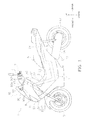
- FIG. 1 is a left side view of the saddle-ride type vehicle 1.
- FIG. 2 is a top view of the saddle-ride type vehicle 1.
- FIG. 2 illustrates a condition that a handle 4 is not turned right and left (i.e., in a straight position).
- the saddle-ride type vehicle 1 includes a vehicle body frame 2, a front fork 3, the handle 4, a front wheel 5, a seat 6, a footboard 7, a center cover 8, a front cover 9, a meter unit 10, an engine 15, a power transmission 16 and a rear wheel 17.
- the terms "back-and-forth direction” and “vehicle width direction” respectively refer to a vehicle back-and-forth direction and a right-and-left direction seen from a rider seated on the seat 6.
- the vehicle body frame 2 is formed by pipes made of iron.
- the vehicle body frame 2 may be integrally shaped by means of bending or so forth, or alternatively, may be formed by integrating a plurality of components by means of welding or so forth.
- the vehicle body frame 2 includes a head pipe 21, a down frame 22, an under frame 23 and a rear frame 24.
- the head pipe 21 is positioned in the middle of the vehicle in the vehicle width direction.
- the down frame 22 is connected to the head pipe 21.
- the down frame 22 is downwardly extended from the head pipe 21.
- the under frame 23 is connected to the lower end portion of the down frame 22.
- the under frame 23 is backwardly extended from the down frame 22.
- the rear frame 24 is connected to the rear end portion of the under frame 23.
- the rear frame 24 is backwardly and upwardly extended from the rear end portion of the under frame 23.
- the front fork 3 includes a steering shaft 31, a bottom bridge 32 and a fork main body 33.
- the steering shaft 31 is inserted into the head pipe 21, while being upwardly extended from the bottom bridge 32.
- the steering shaft 31 is turnably supported by the head pipe 21.
- the steering shaft 31 supports the handle 4.
- the bottom bridge 32 is extended in the vehicle width direction while being located under the head pipe 21.
- the bottom bridge 32 supports the lower end portion of the steering shaft 31.
- the bottom bridge 32 supports the upper end portion of the fork main body 33.
- the fork main body 33 is downwardly extended from the bottom bridge 32.
- the fork main body 33 includes a left support member 33a and a right support member 33b.
- the left and right support members 33a and 33b are disposed on the both sides of the front wheel 5 in the vehicle width direction.
- the handle 4 is supported by the upper end portion of the steering shaft 31.
- the handle 4 is turnable right and left about the steering shaft 31 as an axis.
- the handle 4 includes a handle pipe 41, a left grip 42 and a right grip 43.
- the handle pipe 41 is coupled to the steering shaft 31.
- the handle pipe 41 is extended in the vehicle width direction. As illustrated in FIG. 2 , the handle pipe 41 is formed such that the middle part thereof in the vehicle width direction is protruded forward.
- the left grip 42 is attached to the left end portion of the handle pipe 41.
- the right grip 43 is attached to the right end portion of the handle pipe 41.
- the right and left grips 43 and 42 compose an exemplary pair of holding parts.
- the front wheel 5 is rotatably supported by the lower end portion of the fork main body 33.
- the front wheel 5 is turned right and left in response to right-and-left turning of the handle 4.
- the seat 6 is disposed rearward of the head pipe 21.
- the seat 6 is supported by the rear frame 24.
- the footboard 7 is a plate-shaped member on which a rider seated on the seat 6 puts his/her feet during travelling. As illustrated in FIG. 1 , the rider is allowed to operate the vehicle in a comfortable position with less physical burden by putting his/her feet on the footboard 7.
- the footboard 7 is located between the front wheel 5 and the seat 6 in the back-and-forth direction.
- the footboard 7 is also located between the down frame 22 and the rear frame 24 in the back-and-forth direction. Further, the footboard 7 is located lower than the seat 6. Yet further, the footboard 7 is disposed under the under frame 23. As illustrated in FIG. 2 , the footboard 7 has a left footboard part 71 and a right footboard part 72.
- the right and left footboard parts 72 and 71 are respectively extended in the back-and-forth direction.
- the center cover 8 is disposed between the left footboard part 71 and the right footboard part 72 in the vehicle width direction. As illustrated in FIG. 2 , the center cover 8 has a center part 81, a left side part 82 and a right side part 83.
- the center part 81 is extended in the back-and-forth direction while being located between the seat 6 and the front cover 9.
- the left side part 82 is coupled to the left footboard part 71, while being downwardly extended from the left end portion of the center part 81.
- the right side part 83 is coupled to the right footboard part 72, while being downwardly extended from the right end portion of the center part 81.
- the front cover 9 is disposed under and forward of the handle 4.
- the front cover 9 encloses the head pipe 21 and the steering shaft 31, while being located higher than the front wheel 5.
- the front cover 9 has a front-side cover part 91, a rear-side cover part 92 and a top-side cover part 93.
- the front-side cover part 91 covers the front side and the lateral sides of the head pipe 21.
- the front-side cover part 91 has a U-shape in a top view.
- a headlight 20 is attached to the front surface of the front-side cover part 91.
- the rear-side cover part 92 covers the rear side of the head pipe 21.
- the rear-side cover part 92 is continued to the rear end portion of the front-side cover part 91 and that of the top-side cover part 93.
- the rear-side cover part 92 is continued to the footboard 7 and the center cover 8, while being downwardly extended from the rear end portion of the top-side cover part 93.
- the top-side cover part 93 covers the top side of the head pipe 21.
- the top-side cover part 93 is continued to the upper end portion of the front-side cover part 91 and that of the rear-side cover part 92.
- the top-side cover part 93 has a meter cover part 93a for covering the top side and the lateral sides of the meter unit 10.
- the meter cover part 93a is located in the middle of the vehicle in the vehicle width direction.
- the meter cover part 93a is formed so as to be protruded from the top surface of the top-side cover part 93.
- the meter cover part 93a is tapered forward.
- a screen 30 is attached to the top-side cover part 93.
- the top-side cover part 93 herein has a left-side top surface 93S, a right-side top surface 93T, a left-side intermediate surface 93U and a right-side intermediate surface 93V.
- the right-side and left-side top surfaces 93T and 93S compose an exemplary pair of top surfaces.
- the left-side top surface 93S is extended in the back-and-forth direction, while being located on the left side of the meter unit 10. As illustrated in FIG. 2 , the left-side top surface 93S has a left-side front slope surface S1 and a left-side rear slope surface S2.
- the left-side front slope surface S1 is slanted forward and downward, whereas the left-side rear slope surface S2 is slanted rearward and downward.
- the left-side rear slope surface S2 is continued to the rear end portion of the left-side front slope surface S1.
- the left-side front slope surface S1 is an exemplary front slope surface
- the left-side rear slope surface S2 is an exemplary rear slope surface.
- the right-side top surface 93T is extended in the back-and-forth direction, while being located on the right side of the meter unit 10. As illustrated in FIG. 2 , the right-side top surface 93T has a right-side front slope surface T1 and a right-side rear slope surface T2.
- the right-side front slope surface T1 is slanted forward and downward, whereas the right-side rear slope surface T2 is slanted rearward and downward.
- the right-side rear slope surface T2 is continued to the rear end portion of the right-side front slope surface T1.
- the right-side front slope surface T1 is an exemplary front slope surface
- the right-side rear slope surface T2 is an exemplary rear slope surface.
- the left-side intermediate surface 93U is located higher than the left-side top surface 93S, while being located lower than the meter cover part 93a.
- the left-side intermediate surface 93U is located between the left-side top surface 93S and the meter cover part 93a in the vehicle width direction.
- the left-side intermediate surface 93U is tapered forward.
- the left-side intermediate surface 93U is formed along the left outer edge of the meter cover part 93a. Therefore, the left-side intermediate surface 93U is curved to be gradually closer to the middle of the vehicle to the forward.
- the right-side intermediate surface 93V is located higher than the right-side top surface 93T, while being located lower than the meter cover part 93a. As illustrated in FIG. 2 , the right-side intermediate surface 93V is located between the right-side top surface 93T and the meter cover part 93a in the vehicle width direction. The right-side intermediate surface 93V is tapered forward. The right-side intermediate surface 93V is formed along the right outer edge of the meter cover part 93a. Therefore, the right-side intermediate surface 93V is curved to be gradually closer to the middle of the vehicle to the forward.
- the meter unit 10 is disposed inside the meter cover part 93a.
- the meter unit 10 includes a meter 11 and a translucent cover 12.
- the meter 11 is attached to the top-side cover part 93.
- the translucent cover 12 covers the top side of the meter 11.
- the translucent cover 12 is a protection member for preventing intrusion of dust and moisture into the meter 11.
- the translucent cover 12 is made of translucent material such as plastic or glass. When seated on the seat 6, a rider can visually check the meter 11 through the translucent cover 12.
- the upper end of the translucent cover 12 is located forward of the lower end thereof. In other words, the translucent cover 12 is slanted forward.
- the translucent cover 12 can be formed in a flat-plate shape. Alternatively, the translucent cover 12 may be partially or entirely curved.
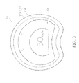
- FIG. 3 is herein a plan view of a structure of the meter unit 10.
- the meter 11 includes a display part 11a and an outer shell part 11 b.
- the display part 11 a is configured to display a speed meter, a variety of alarm lamps and so forth.
- the translucent cover 12 is disposed on the display part 11 a.
- the outer shell part 11 b encloses the outer circumference of the display part 11 a.
- the outer shell part 11 b restricts incident light into the display part 11 a in order to enhance visibility of the display part 11 a.
- the engine 15 is an internal combustion engine configured to generate driving force.
- the driving force, generated by the engine 15, is transmitted to the rear wheel 17 through the power transmission 16.
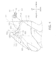
- FIG. 4 is an enlarged left side view of the saddle-ride type vehicle 1.
- FIG. 5 is an enlarged right side view of the saddle-ride type vehicle 1.
- FIGS. 4 and 5 illustrate a condition that the handle 4 is not being turned right and left.
- a left rear end 91 Lb of the front-side cover part 91 is located forward of the left grip 42. Therefore, the left grip 42 is located rearward of a vertical line V1 for indicating the back-and-forth position of the left rear end 91 Lb.
- the left rear end 91 Lb is formed on the upper part of the front cover 9. More specifically, as illustrated in FIG. 4 , the left rear end 91 Lb is located on the upper end of a joint line between the front-side cover part 91 and the rear-side cover part 92. Likewise, a right rear end 91 Rb of the front-side cover part 91 is located forward of the right grip 43.
- the right grip 43 is located rearward of a vertical line V2 for indicating the back-and-forth position of the right rear end 91 Rb.
- the right rear end 91 Rb is formed on the upper part of the front cover 9. More specifically, as illustrated in FIG. 5 , the right rear end 91 Rb is located on the upper end of the joint line between the front-side cover part 91 and the rear-side cover part 92. It should be noted that in the present exemplary embodiment, the back-and-forth position of the vertical line V1 is the same as that of and the vertical line V2.
- An upper end 12P of the translucent cover 12 is located higher than the left grip 42. Therefore, the left grip 42 is located lower than a horizontal line H1 for indicating the up-and-down position of the upper end 12P. Likewise, the upper end 12P of the translucent cover 12 is located higher than the right grip 43. Therefore, the right grip 43 is located lower than the horizontal line H1.
- the upper end 12P of the translucent cover 12 is located forward of a lower end 12Q of the translucent cover 12. As illustrated in FIG. 4 , the lower end 12Q of the translucent cover 12 is located rearward of a vertical line V3 for indicating the center of the front-side cover part 91 in the back-and-forth direction. In the present exemplary embodiment, the upper end 12P of the translucent cover 12 is also located rearward of the vertical line V3.
- the left-side top surface 93S is located lower than a center 12C of the translucent cover 12 in the up-and-down direction.
- the right-side top surface 93T is located lower than the center 12C.
- the right-side and left-side top surfaces 93T and 93S are located lower than the lower end 12Q of the translucent cover 12.
- the left-side rear slope surface S2 of the left-side top surface 93S is located leftward of the translucent cover 12.
- the right-side rear slope surface T2 of the right-side top surface 93T is located rightward of the translucent cover 12.
- the translucent cover 12 is further slanted with respect to the horizontal direction than the left-side rear slope surface S2 is. Therefore, a slant angle ⁇ 1 of the left-side rear slope surface S2 with respect to a horizontal line H2 is less than a slant angle 82 of the translucent cover 12 with respect to the horizontal line H2.
- the translucent cover 12 is further slanted with respect to the horizontal direction than the right-side rear slope surface T2 is. Therefore, a slant angle ⁇ 3 of the right-side rear slope surface T2 with respect to the horizontal line H2 is less than the slant angle ⁇ 2 of the translucent cover 12 with respect to the horizontal line H2.
- a height T12 of the translucent cover 12 in the up-and-down direction is herein greater than a depth S12 of the translucent cover 12 in the back-and-forth direction. Therefore, the slant angle ⁇ 2 of the translucent cover 12 with respect to the horizontal line H2 is greater than 45 degrees.
- the left-side front slope surface S1 is further slanted with respect to the horizontal direction than the left-side rear slope surface S2 is.
- the slant angle ⁇ 1 of the left-side rear slope surface S2 with respect to the horizontal line H2 is less than a slant angle ⁇ 4 of the left-side front slope surface S1 with respect to the horizontal line H2.
- the right-side front slope surface T1 is further slanted with respect to the horizontal direction than the right-side rear slope surface T2 is.
- the slant angle ⁇ 3 of the right-side rear slope surface T2 with respect to the horizontal line H2 is less than a slant angle ⁇ 5 of the right-side front slope surface T1 with respect to the horizontal line H2.
- the right-side and left-side rear slope surfaces T2 and S2 may be arranged roughly in parallel to a horizontal plane.
- the slant angle ⁇ 1 of the left-side rear slope surface S2 and the slant angle ⁇ 3 of the right-side rear slope surface T2 may be roughly 0 degrees.
- An interval D1 produced between the translucent cover 12 and the left-side rear slope surface S2 in the up-and-down direction is gradually increased forward.
- an interval D2 produced between the translucent cover 12 and the right-side rear slope surface T2 in the up-and-down direction is gradually increased forward.
- the intervals D1 and D2 are roughly equal to each other.
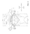
- FIG. 6 is a plan view of the saddle-ride type vehicle 1 seen in a direction perpendicular to the translucent cover 12.
- the point of view in FIG. 6 can be considered as a line of sight of a rider seated on the seat 6.
- FIG. 6 illustrates a condition that the handle 4 is not being turned right and left.
- the width (W12) of the translucent cover 12 is less than one-third of the width (W93) of the top-side cover part 93.
- the interval (D3) produced between the left end of the translucent cover 12 and that of the top-side cover part 93 is greater than the width W12 of the translucent cover 12.
- the interval (D4) produced between the right end of the translucent cover 12 and that of the top-side cover part 93 is greater than the width W12 of the translucent cover 12.
- the intervals D3 and D4 are roughly equivalent to each other. It should be noted that the right/left end of the translucent cover 12 is an exemplary outer edge of the translucent cover 12, whereas the right/left end of the top-side cover part 93 is an exemplary outer edge of the top-side cover part 93.
- the width W12 of the translucent cover 12 is greater than the length (L12) of the translucent cover 12 in the back-and-forth direction.
- the total width (TW1) of the left-side intermediate surface 93U and the meter cover part 93a is less than the width W12 of the translucent cover 12 on a reference line SL arranged in parallel to a right-and-left direction passing through the center 12C of the translucent cover 12. Further, the total width TW1 of the left-side intermediate surface 93U and the meter cover part 93a is less than the width (W93S) of the left-side top surface 93S on the reference line SL.
- the total width (TW2) of the right-side intermediate surface 93V and the meter cover part 93a is less than the width W12 of the translucent cover 12 on the reference line SL.
- the total width TW2 of the right-side intermediate surface 93V and the meter cover part 93a is less than the width (W93T) of the right-side top surface 93T on the reference line SL.
- the width W12 of the translucent cover 12 is less than the width (W3) of the front fork 3.
- the width W3 of the front fork 3 is either the width of the bottom bridge 32 or that of the fork main body 33.
- the handle 4 is overlapped with the meter unit 10. It should be noted that the handle 4 is separated away from the display part 11a of the meter unit 10. In other words, the handle 4 is not overlapped with the display part 11 a.
- FIG. 7 is herein a plan view that is basically the same as FIG 6 . However, FIG. 7 illustrates a condition that the handle 4 is turned at the maximum angle in the counterclockwise direction.
- the translucent cover 12 is not overlapped with the right grip 43 and the left grip 42. Especially, the translucent cover 12 is not overlapped with the left grip 42 inwardly moved in the vehicle width direction in accordance with turning of the handle 4. The translucent cover 12 is disposed between the right grip 43 and the left grip 42 in the vehicle width direction.
- the structure and configuration herein described are also true to a condition that the handle 4 is turned at the maximum angle in the clockwise direction.
- the front fork 3 includes the bottom bridge 32 for supporting the lower end portion of the steering shaft 31 and the upper end portion of the fork main body 33. Further, the right and left rear ends 91 Rb and 91 Lb of the front-side cover part 91 are located forward of the right and left grips 43 and 42 in a side view.
- the steering shaft 31 is allowed to be enclosed by the front cover 9. Therefore, in comparison with the structure that the fork main body 33 is extended to the same height as the steering shaft 31, the front cover 9 can be further reduced in its size and the riding position of a rider can be moved further forward. As a result, the top-side cover part 93 can be entirely lowered, and forward visibility can be enhanced.
- the top-side cover part 93 has the right-side top surface 93T and the left-side top surface 93S (an exemplary pair of top surfaces) that are extended in the back-and-forth direction while being located laterally to the translucent cover 12.
- the right-side and left-side top surfaces 93T and 93S are located lower than the center 12C of the translucent cover 12 in the up-and-down direction.
- the inventors of the present application noticed that different visual ranges are desired by a rider with respect to a situation during travelling in a straight direction and a situation in approaching to an intersection. Meanwhile, the inventors reached a conclusion that forward visibility can be divided into straightly forward visibility and obliquely forward visibility. Further, the inventors especially obtained the finding that required forward visibility can be maintained during riding on a vehicle by expanding a near-side obliquely forward visual range.
- the travelling direction of a vehicle is not changed during travelling in a straight direction.
- forward visibility is less affected by the fact that the road surface straight ahead is not visible on the near side of a rider.
- forward visibility is unlikely to be degraded even when the height of the vehicle is high in its middle part in the vehicle width direction.
- the travelling direction of the vehicle is changed into right or left in approaching to an intersection.
- forward visibility is greatly affected by the fact that the near-side obliquely forward visual range is narrow.
- forward visibility is remarkably degraded when the height of the vehicle is high on its both sides in the vehicle width direction.
- the right-side top surface 93T and the left-side top surface 93S are formed on the both sides of the meter unit 10 protruded from the top-side cover part 93 in the saddle-ride type vehicle 1 according to the present exemplary embodiment. Therefore, visibility of the meter 11 can be enhanced, while required forward visibility can be maintained by expanding the near-side obliquely forward visual range.
- forward visibility of the vehicle and visibility of the meter 11 can be both enhanced while a raider operates the vehicle in a comfortable riding position.
- forward visibility of a vehicle and visibility of a meter can be enhanced in a comfortable riding position.
- the present teaching is useful for the field of saddle-ride type vehicles.
Landscapes
- Engineering & Computer Science (AREA)
- Mechanical Engineering (AREA)
- Steering Devices For Bicycles And Motorcycles (AREA)
Abstract
Description
- The present invention relates to a saddle-ride type vehicle.
- A type of saddle-ride type vehicle, which has been well-known so far, includes a front fork, a front cover enclosing the front fork and a footboard disposed rearward of the front cover (see
JP H11-303699 A - Now, in
JP H11-303699 A - According to the saddle-ride type vehicle described in
JP H11-303699 A - Incidentally,
JP-A-2010-163879 - Moreover, a saddle-ride type vehicle described in
JP-A-2010-163879 - In such a saddle-ride type vehicle, reduction in size of the front cover can be achieved by lowering the height of the front cover to which the meter unit is attached.
- However, when forward visibility is enhanced by lowering the height of the front cover, the position of the meter unit is accordingly lowered. Therefore, visibility of the meter unit is inevitably degraded.
- It is an object of the present invention to provide a saddle-ride type vehicle whereby forward visibility of the vehicle and visibility of a meter can be both enhanced in a comfortable riding position.
- According to the present invention said object is solved by a saddle-ride type vehicle having the features of independent claim 1. Preferred embodiments are laid down in the dependent claims.
- Accordingly, a saddle-ride type vehicle according to a first aspect includes a head pipe, a front fork, a handle, a front wheel, a seat, a footboard, a front cover and a meter unit. The front fork includes a steering shaft, a bottom bridge and a fork main body. The steering shaft is turnably supported by the head pipe. The bottom bridge supports a lower end portion of the steering shaft. The upper end portion of the fork main body is supported by the bottom bridge. The handle is supported by an upper end portion of the steering shaft and has a pair of holding parts. The front wheel is supported by a lower end portion of the fork main body. The seat is disposed rearward of the head pipe in a back-and-forth direction. The footboard is disposed forward of and lower than the seat. The front cover includes a front-side cover part, a rear-side cover part and a top-side cover part. The front-side cover part covers a front side and lateral sides of the head pipe. The rear-side cover part covers a rear side of the head pipe and is continued to a rear end portion of the front-side cover part The top-side cover part covers a top side of the head pipe and is continued to an upper end portion of the front-side cover part and an upper end portion of the rear-side cover part. The a meter unit includes a meter and a translucent cover. The meter is attached to the top-side cover part. The translucent cover covers a top side of the meter and is slanted forward. A rear end of the front-side cover part is located forward of the pair of holding parts in a side view. An upper end of the translucent cover is located higher than the pair of holding parts in the side view. The top-side cover part has a pair of top surfaces. The top surfaces extends in the back-and-forth direction on both sides of the meter unit in a vehicle width direction. The pair of top surfaces is located lower than a center of the translucent cover in an up-and-down direction.
- A saddle-ride type vehicle according to a second aspect relates to the saddle-ride type vehicle according to the first aspect, and wherein a width of the translucent cover in the vehicle width direction is less than one-third of a width of the top-side cover part in the vehicle width direction.
- A saddle-ride type vehicle according to a third aspect relates to the saddle-ride type vehicle according to the first or second aspect, and wherein an interval produced between an outer edge of the translucent cover and an outer edge of the top-side cover part in the vehicle width direction is greater than a width of the translucent cover in the vehicle width direction when viewed from a direction perpendicular to the translucent cover. The width of the translucent cover in the vehicle width direction is greater than a length of the translucent cover in the back-and-forth direction when viewed from the direction perpendicular to the translucent cover.
- A saddle-ride type vehicle according to a fourth aspect relates to the saddle-ride type vehicle according to any of the first to third aspects, and wherein a width of the translucent cover in the vehicle width direction is less than a width of the front fork in the vehicle width direction.
- A saddle-ride type vehicle according to a fifth aspect relates to the saddle-ride type vehicle according to any of the first to fourth aspects, and wherein the translucent cover is configured not to be overlapped with the pair of holding parts when viewed from a direction perpendicular to the translucent cover in a case where the handle is turned at a maximum angle.
- A saddle-ride type vehicle according to a sixth aspect relates to the saddle-ride type vehicle according to the fifth aspect, and wherein the translucent cover is configured to be located between the pair of holding parts in the vehicle width direction in the case where the handle is turned at the maximum angle.
- A saddle-ride type vehicle according to a seventh aspect relates to the saddle-ride type vehicle according to any of the first to sixth aspects, and wherein each of the pair of top surfaces has a front slope surface and a rear slope surface. The front slope surface is slanted forward and downward. The rear slope surface is slanted rearward and downward and is continued to a rear end portion of the front slope surface.
- A saddle-ride type vehicle according to an eighth aspect relates to the saddle-ride type vehicle according to the seventh aspect, and wherein the rear slope surface is located laterally to the translucent cover in the vehicle width direction.
- A saddle-ride type vehicle according to a ninth aspect relates to the saddle-ride type vehicle according to the seventh or eighth aspect, and wherein a slant angle of the rear slope surface with respect to a horizontal direction is less than a slant angle of the translucent cover with respect to the horizontal direction.
- A saddle-ride type vehicle according to a tenth aspect relates to the saddle-ride type vehicle according to any of the seventh to ninth aspects, and wherein an interval produced between the translucent cover and the rear slope surface in the up-and-down direction is gradually increased forward.
- A saddle-ride type vehicle according to an eleventh aspect relates to the saddle-ride type vehicle according to any of the seventh to tenth aspects, and wherein a slant angle of the rear slope surface with respect to a horizontal direction is less than a slant angle of the front slope surface with respect to the horizontal direction.
- A saddle-ride type vehicle according to a twelfth aspect relates to the saddle-ride type vehicle according to any of the first to eleventh aspects, and wherein a height of the translucent cover in the up-and-down direction is greater than a depth of the translucent cover in the back-and-forth direction.
- A saddle-ride type vehicle according to a thirteenth aspect relates to the saddle-ride type vehicle according to the first to twelfth aspects, and wherein the upper end of the translucent cover is located rearward of a center of the front-side cover part in the back-and-forth direction.
- A saddle-ride type vehicle according to a fourteenth aspect relates to the saddle-ride type vehicle according to the first to thirteenth aspects, and wherein the handle is overlapped with the meter unit when viewed from a direction perpendicular to the translucent cover.
- A saddle-ride type vehicle according to a fifteenth aspect relates to the saddle-ride type vehicle according to the fourteenth aspect, and wherein the meter unit includes a display part which is configured to display a speed meter and an alarm lamp. The handle is separated away from the display part when viewed from the direction perpendicular to the translucent cover.
- The saddle-ride type vehicle according to the first aspect includes the footboard on which a rider seated on the seat puts his/her feet during travelling. Therefore, the rider can operate the vehicle in a riding position with less physical burden. Further, the front fork includes the bottom bridge for supporting the lower end portion of the steering shaft and the upper end portion of the fork main body. Yet further, the rear end of the front-side cover part is located forward of the pair of holding parts in a side view. Thus, the steering shaft is allowed to be enclosed by the front cover. Therefore, in comparison with a structure that the fork main body is extended to the same height as the steering shaft, the front cover can be further reduced in its size and the riding position of a rider can be moved further forward. As a result, the top-side cover part can be entirely lowered, and forward visibility can be enhanced. Further, the top-side cover part has the pair of top surfaces that are extended in the back-and-forth direction while being located laterally to the translucent cover. The pair of top surfaces is located lower than the center of the translucent cover in the up-and-down direction. Incidentally, as a result of keen examination, the inventors of the present application noticed that different visual ranges are desired by a rider with respect to a situation during travelling in a straight direction and a situation in approaching to an intersection. As a result, the inventors reached a conclusion that forward visibility can be divided into straightly forward visibility and obliquely forward visibility. Further, the inventors especially obtained the finding that required forward visibility can be maintained during riding on a vehicle by expanding a near-side obliquely forward visual range. In view of the above, the pair of top surfaces is formed on the both sides of the meter unit protruded from the top-side cover part in the present saddle-ride type vehicle. Therefore, visibility of the meter can be enhanced, while required forward visibility can be maintained during riding on the vehicle by extending the near-side obliquely forward visual range. As a result, forward visibility of the vehicle and visibility of the meter can be both enhanced while a raider operates the vehicle in a comfortable riding position.
- In the saddle-ride type vehicle according to the second aspect, the field of view in the obliquely forward direction is extended. Therefore, forward visibility can be enhanced.
- In the saddle-ride type vehicle according to the third aspect, the field of view in the obliquely forward direction is extended, while the translucent cover is formed with a narrow width. Therefore, forward visibility can be further enhanced.
- In the saddle-ride type vehicle according to the fourth aspect, the translucent cover is formed with a narrow width. Therefore, forward visibility can be enhanced.
- In the saddle-ride type vehicle according to the fifth aspect, the translucent cover is not blocked by the pair of holding parts, for instance, even during turning of the saddle-ride type vehicle. Therefore, visibility of the meter can be further enhanced.
- In the saddle-ride type vehicle according to the sixth aspect, the translucent cover is not blocked by the pair of holding parts, for instance, even during turning of the saddle-ride type vehicle. Therefore, visibility of the meter can be further enhanced.
- In the saddle-ride type vehicle according to the seventh aspect, the pair of top surfaces is downwardly cut to the forward. The field of view on the near side is herein further extended in comparison with the structure that the pair of top surfaces is flat. Therefore, forward visibility can be further enhanced.
- In the saddle-ride type vehicle according to the eighth aspect, the meter unit can be herein located more rearward in comparison with the structure that the translucent cover is located laterally to the front slope surface. In other words, the meter unit can be located closer to a rider. Therefore, visibility of the meter can be further enhanced.
- In the saddle-ride type vehicle according to the ninth aspect, the rise of the rear slope surface is suppressed. Therefore, it is possible to inhibit occurrence of such a situation that obliquely forward visibility is degraded by the rear slope surface. Further, the meter unit can be located closer to a rider while being raised. Therefore, visibility of the meter can be further enhanced.
- In the saddle-ride type vehicle according to the tenth aspect, the meter unit can be located closer to a rider while being raised. Therefore, visibility of the meter can be further enhanced.
- In the saddle-ride type vehicle according to the eleventh aspect, the slant of the rear slope surface can be suppressed. Where the height of the head pipe is set constant, the height of the front end of the rear slope surface can be lowered. Therefore, obliquely forward visibility can be further enhanced.
- In the saddle-ride type vehicle according to the twelfth aspect, the meter unit can be located closer to a rider while being raised. Therefore, visibility of the meter can be further enhanced.
- In the saddle-ride type vehicle according to the thirteenth aspect, the meter unit is located closer to a rider. Therefore, visibility of the meter can be further enhanced.
- In the saddle-ride type vehicle according to the fourteenth aspect, the meter unit is located closer to the handle. Therefore, the meter unit can be located further closer to a rider.
- In the saddle-ride type vehicle according to the fifteenth aspect, required visibility of the meter can be reliably achieved, while the meter unit can be located closer to a rider.
- Referring now to the attached drawings which form a part of this original disclosure:
-
FIG. 1 is a left side view of a saddle-ride type vehicle according to an exemplary embodiment; -
FIG. 2 is a top view of the saddle-ride type vehicle; -
FIG. 3 is a plan view of a meter unit; -
FIG. 4 is an enlarged left side view of the saddle-ride type vehicle; -
FIG. 5 is an enlarged right side view of the saddle-ride type vehicle; -
FIG. 6 is a plan view seen in a direction perpendicular to a translucent cover of the saddle-ride type vehicle; and -
FIG. 7 is a plan view seen in the direction perpendicular to the translucent cover of the saddle-ride type vehicle. - With reference to the attached drawings, explanation will be hereinafter made for a schematic structure of a saddle-ride type vehicle 1 according to an exemplary embodiment.
FIG. 1 is a left side view of the saddle-ride type vehicle 1.FIG. 2 is a top view of the saddle-ride type vehicle 1.FIG. 2 illustrates a condition that ahandle 4 is not turned right and left (i.e., in a straight position). - The saddle-ride type vehicle 1 includes a
vehicle body frame 2, afront fork 3, thehandle 4, afront wheel 5, aseat 6, afootboard 7, a center cover 8, a front cover 9, ameter unit 10, anengine 15, apower transmission 16 and arear wheel 17. It should be noted that in the following explanation, the terms "back-and-forth direction" and "vehicle width direction" respectively refer to a vehicle back-and-forth direction and a right-and-left direction seen from a rider seated on theseat 6. - The
vehicle body frame 2 is formed by pipes made of iron. Thevehicle body frame 2 may be integrally shaped by means of bending or so forth, or alternatively, may be formed by integrating a plurality of components by means of welding or so forth. - As illustrated in
FIG. 1 , thevehicle body frame 2 includes ahead pipe 21, adown frame 22, an underframe 23 and arear frame 24. Thehead pipe 21 is positioned in the middle of the vehicle in the vehicle width direction. The downframe 22 is connected to thehead pipe 21. The downframe 22 is downwardly extended from thehead pipe 21. The underframe 23 is connected to the lower end portion of thedown frame 22. The underframe 23 is backwardly extended from thedown frame 22. Therear frame 24 is connected to the rear end portion of theunder frame 23. Therear frame 24 is backwardly and upwardly extended from the rear end portion of theunder frame 23. - The
front fork 3 includes a steeringshaft 31, abottom bridge 32 and a forkmain body 33. The steeringshaft 31 is inserted into thehead pipe 21, while being upwardly extended from thebottom bridge 32. The steeringshaft 31 is turnably supported by thehead pipe 21. The steeringshaft 31 supports thehandle 4. Thebottom bridge 32 is extended in the vehicle width direction while being located under thehead pipe 21. Thebottom bridge 32 supports the lower end portion of the steeringshaft 31. Thebottom bridge 32 supports the upper end portion of the forkmain body 33. The forkmain body 33 is downwardly extended from thebottom bridge 32. As illustrated inFIG. 2 , the forkmain body 33 includes aleft support member 33a and aright support member 33b. The left andright support members front wheel 5 in the vehicle width direction. - The
handle 4 is supported by the upper end portion of the steeringshaft 31. Thehandle 4 is turnable right and left about the steeringshaft 31 as an axis. As illustrated inFIG. 2 , thehandle 4 includes ahandle pipe 41, aleft grip 42 and aright grip 43. - The
handle pipe 41 is coupled to the steeringshaft 31. Thehandle pipe 41 is extended in the vehicle width direction. As illustrated inFIG. 2 , thehandle pipe 41 is formed such that the middle part thereof in the vehicle width direction is protruded forward. Theleft grip 42 is attached to the left end portion of thehandle pipe 41. Theright grip 43 is attached to the right end portion of thehandle pipe 41. The right and leftgrips - The
front wheel 5 is rotatably supported by the lower end portion of the forkmain body 33. Thefront wheel 5 is turned right and left in response to right-and-left turning of thehandle 4. Theseat 6 is disposed rearward of thehead pipe 21. Theseat 6 is supported by therear frame 24. - The
footboard 7 is a plate-shaped member on which a rider seated on theseat 6 puts his/her feet during travelling. As illustrated inFIG. 1 , the rider is allowed to operate the vehicle in a comfortable position with less physical burden by putting his/her feet on thefootboard 7. Thefootboard 7 is located between thefront wheel 5 and theseat 6 in the back-and-forth direction. Thefootboard 7 is also located between thedown frame 22 and therear frame 24 in the back-and-forth direction. Further, thefootboard 7 is located lower than theseat 6. Yet further, thefootboard 7 is disposed under the underframe 23. As illustrated inFIG. 2 , thefootboard 7 has aleft footboard part 71 and aright footboard part 72. The right and leftfootboard parts - The center cover 8 is disposed between the
left footboard part 71 and theright footboard part 72 in the vehicle width direction. As illustrated inFIG. 2 , the center cover 8 has acenter part 81, aleft side part 82 and aright side part 83. Thecenter part 81 is extended in the back-and-forth direction while being located between theseat 6 and the front cover 9. Theleft side part 82 is coupled to theleft footboard part 71, while being downwardly extended from the left end portion of thecenter part 81. Theright side part 83 is coupled to theright footboard part 72, while being downwardly extended from the right end portion of thecenter part 81. - The front cover 9 is disposed under and forward of the
handle 4. The front cover 9 encloses thehead pipe 21 and the steeringshaft 31, while being located higher than thefront wheel 5. The front cover 9 has a front-side cover part 91, a rear-side cover part 92 and a top-side cover part 93. - The front-
side cover part 91 covers the front side and the lateral sides of thehead pipe 21. The front-side cover part 91 has a U-shape in a top view. Aheadlight 20 is attached to the front surface of the front-side cover part 91. - The rear-
side cover part 92 covers the rear side of thehead pipe 21. The rear-side cover part 92 is continued to the rear end portion of the front-side cover part 91 and that of the top-side cover part 93. The rear-side cover part 92 is continued to thefootboard 7 and the center cover 8, while being downwardly extended from the rear end portion of the top-side cover part 93. - The top-
side cover part 93 covers the top side of thehead pipe 21. The top-side cover part 93 is continued to the upper end portion of the front-side cover part 91 and that of the rear-side cover part 92. The top-side cover part 93 has ameter cover part 93a for covering the top side and the lateral sides of themeter unit 10. Themeter cover part 93a is located in the middle of the vehicle in the vehicle width direction. Themeter cover part 93a is formed so as to be protruded from the top surface of the top-side cover part 93. Themeter cover part 93a is tapered forward. Ascreen 30 is attached to the top-side cover part 93. - The top-
side cover part 93 herein has a left-side top surface 93S, a right-sidetop surface 93T, a left-sideintermediate surface 93U and a right-sideintermediate surface 93V. The right-side and left-side top surfaces 93T and 93S compose an exemplary pair of top surfaces. - The left-
side top surface 93S is extended in the back-and-forth direction, while being located on the left side of themeter unit 10. As illustrated inFIG. 2 , the left-side top surface 93S has a left-side front slope surface S1 and a left-side rear slope surface S2. The left-side front slope surface S1 is slanted forward and downward, whereas the left-side rear slope surface S2 is slanted rearward and downward. The left-side rear slope surface S2 is continued to the rear end portion of the left-side front slope surface S1. The left-side front slope surface S1 is an exemplary front slope surface, whereas the left-side rear slope surface S2 is an exemplary rear slope surface. - The right-side
top surface 93T is extended in the back-and-forth direction, while being located on the right side of themeter unit 10. As illustrated inFIG. 2 , the right-sidetop surface 93T has a right-side front slope surface T1 and a right-side rear slope surface T2. The right-side front slope surface T1 is slanted forward and downward, whereas the right-side rear slope surface T2 is slanted rearward and downward. The right-side rear slope surface T2 is continued to the rear end portion of the right-side front slope surface T1. The right-side front slope surface T1 is an exemplary front slope surface, whereas the right-side rear slope surface T2 is an exemplary rear slope surface. - As illustrated in
FIG. 1 , the left-sideintermediate surface 93U is located higher than the left-side top surface 93S, while being located lower than themeter cover part 93a. As illustrated inFIG. 2 , the left-sideintermediate surface 93U is located between the left-side top surface 93S and themeter cover part 93a in the vehicle width direction. The left-sideintermediate surface 93U is tapered forward. The left-sideintermediate surface 93U is formed along the left outer edge of themeter cover part 93a. Therefore, the left-sideintermediate surface 93U is curved to be gradually closer to the middle of the vehicle to the forward. - The right-side
intermediate surface 93V is located higher than the right-sidetop surface 93T, while being located lower than themeter cover part 93a. As illustrated inFIG. 2 , the right-sideintermediate surface 93V is located between the right-sidetop surface 93T and themeter cover part 93a in the vehicle width direction. The right-sideintermediate surface 93V is tapered forward. The right-sideintermediate surface 93V is formed along the right outer edge of themeter cover part 93a. Therefore, the right-sideintermediate surface 93V is curved to be gradually closer to the middle of the vehicle to the forward. - The
meter unit 10 is disposed inside themeter cover part 93a. Themeter unit 10 includes ameter 11 and atranslucent cover 12. Themeter 11 is attached to the top-side cover part 93. Thetranslucent cover 12 covers the top side of themeter 11. Thetranslucent cover 12 is a protection member for preventing intrusion of dust and moisture into themeter 11. Thetranslucent cover 12 is made of translucent material such as plastic or glass. When seated on theseat 6, a rider can visually check themeter 11 through thetranslucent cover 12. The upper end of thetranslucent cover 12 is located forward of the lower end thereof. In other words, thetranslucent cover 12 is slanted forward. Thetranslucent cover 12 can be formed in a flat-plate shape. Alternatively, thetranslucent cover 12 may be partially or entirely curved. -
FIG. 3 is herein a plan view of a structure of themeter unit 10. As illustrated inFIG. 3 , themeter 11 includes adisplay part 11a and anouter shell part 11 b. Thedisplay part 11 a is configured to display a speed meter, a variety of alarm lamps and so forth. Thetranslucent cover 12 is disposed on thedisplay part 11 a. Theouter shell part 11 b encloses the outer circumference of thedisplay part 11 a. Theouter shell part 11 b restricts incident light into thedisplay part 11 a in order to enhance visibility of thedisplay part 11 a. - The
engine 15 is an internal combustion engine configured to generate driving force. The driving force, generated by theengine 15, is transmitted to therear wheel 17 through thepower transmission 16. - Next, with reference to the drawings, explanation will be made for positional relations among respective elements in a side view.
FIG. 4 is an enlarged left side view of the saddle-ride type vehicle 1.FIG. 5 is an enlarged right side view of the saddle-ride type vehicle 1.FIGS. 4 and5 illustrate a condition that thehandle 4 is not being turned right and left. - A left
rear end 91 Lb of the front-side cover part 91 is located forward of theleft grip 42. Therefore, theleft grip 42 is located rearward of a vertical line V1 for indicating the back-and-forth position of the leftrear end 91 Lb. The leftrear end 91 Lb is formed on the upper part of the front cover 9. More specifically, as illustrated inFIG. 4 , the leftrear end 91 Lb is located on the upper end of a joint line between the front-side cover part 91 and the rear-side cover part 92. Likewise, a rightrear end 91 Rb of the front-side cover part 91 is located forward of theright grip 43. Therefore, theright grip 43 is located rearward of a vertical line V2 for indicating the back-and-forth position of the rightrear end 91 Rb. The rightrear end 91 Rb is formed on the upper part of the front cover 9. More specifically, as illustrated inFIG. 5 , the rightrear end 91 Rb is located on the upper end of the joint line between the front-side cover part 91 and the rear-side cover part 92. It should be noted that in the present exemplary embodiment, the back-and-forth position of the vertical line V1 is the same as that of and the vertical line V2. - An
upper end 12P of thetranslucent cover 12 is located higher than theleft grip 42. Therefore, theleft grip 42 is located lower than a horizontal line H1 for indicating the up-and-down position of theupper end 12P. Likewise, theupper end 12P of thetranslucent cover 12 is located higher than theright grip 43. Therefore, theright grip 43 is located lower than the horizontal line H1. - The
upper end 12P of thetranslucent cover 12 is located forward of alower end 12Q of thetranslucent cover 12. As illustrated inFIG. 4 , thelower end 12Q of thetranslucent cover 12 is located rearward of a vertical line V3 for indicating the center of the front-side cover part 91 in the back-and-forth direction. In the present exemplary embodiment, theupper end 12P of thetranslucent cover 12 is also located rearward of the vertical line V3. - The left-
side top surface 93S is located lower than acenter 12C of thetranslucent cover 12 in the up-and-down direction. Likewise, the right-sidetop surface 93T is located lower than thecenter 12C. Further, in the present exemplary embodiment, the right-side and left-side top surfaces 93T and 93S are located lower than thelower end 12Q of thetranslucent cover 12. - The left-side rear slope surface S2 of the left-
side top surface 93S is located leftward of thetranslucent cover 12. Likewise, the right-side rear slope surface T2 of the right-sidetop surface 93T is located rightward of thetranslucent cover 12. - The
translucent cover 12 is further slanted with respect to the horizontal direction than the left-side rear slope surface S2 is. Therefore, a slant angle θ1 of the left-side rear slope surface S2 with respect to a horizontal line H2 is less than aslant angle 82 of thetranslucent cover 12 with respect to the horizontal line H2. Likewise, thetranslucent cover 12 is further slanted with respect to the horizontal direction than the right-side rear slope surface T2 is. Therefore, a slant angle θ3 of the right-side rear slope surface T2 with respect to the horizontal line H2 is less than the slant angle θ2 of thetranslucent cover 12 with respect to the horizontal line H2. - As illustrated in
FIG. 5 , a height T12 of thetranslucent cover 12 in the up-and-down direction is herein greater than a depth S12 of thetranslucent cover 12 in the back-and-forth direction. Therefore, the slant angle θ2 of thetranslucent cover 12 with respect to the horizontal line H2 is greater than 45 degrees. - The left-side front slope surface S1 is further slanted with respect to the horizontal direction than the left-side rear slope surface S2 is. In other words, the slant angle θ1 of the left-side rear slope surface S2 with respect to the horizontal line H2 is less than a slant angle θ4 of the left-side front slope surface S1 with respect to the horizontal line H2. Likewise, the right-side front slope surface T1 is further slanted with respect to the horizontal direction than the right-side rear slope surface T2 is. In other words, the slant angle θ3 of the right-side rear slope surface T2 with respect to the horizontal line H2 is less than a slant angle θ5 of the right-side front slope surface T1 with respect to the horizontal line H2. The right-side and left-side rear slope surfaces T2 and S2 may be arranged roughly in parallel to a horizontal plane. In other words, the slant angle θ1 of the left-side rear slope surface S2 and the slant angle θ3 of the right-side rear slope surface T2 may be roughly 0 degrees.
- An interval D1 produced between the
translucent cover 12 and the left-side rear slope surface S2 in the up-and-down direction is gradually increased forward. Likewise, an interval D2 produced between thetranslucent cover 12 and the right-side rear slope surface T2 in the up-and-down direction is gradually increased forward. In the present exemplary embodiment, the intervals D1 and D2 are roughly equal to each other. - Next, with reference to the drawings, explanation will be made for positional relations among respective elements in a plan view.
FIG. 6 is a plan view of the saddle-ride type vehicle 1 seen in a direction perpendicular to thetranslucent cover 12. The point of view inFIG. 6 can be considered as a line of sight of a rider seated on theseat 6.FIG. 6 illustrates a condition that thehandle 4 is not being turned right and left. - In the vehicle width direction, the width (W12) of the
translucent cover 12 is less than one-third of the width (W93) of the top-side cover part 93. - In the vehicle width direction, the interval (D3) produced between the left end of the
translucent cover 12 and that of the top-side cover part 93 is greater than the width W12 of thetranslucent cover 12. Likewise, in the vehicle width direction, the interval (D4) produced between the right end of thetranslucent cover 12 and that of the top-side cover part 93 is greater than the width W12 of thetranslucent cover 12. In the present exemplary embodiment, the intervals D3 and D4 are roughly equivalent to each other. It should be noted that the right/left end of thetranslucent cover 12 is an exemplary outer edge of thetranslucent cover 12, whereas the right/left end of the top-side cover part 93 is an exemplary outer edge of the top-side cover part 93. - In the view of the direction perpendicular to the
translucent cover 12, the width W12 of thetranslucent cover 12 is greater than the length (L12) of thetranslucent cover 12 in the back-and-forth direction. - In the view of the direction perpendicular to the
translucent cover 12, the total width (TW1) of the left-sideintermediate surface 93U and themeter cover part 93a is less than the width W12 of thetranslucent cover 12 on a reference line SL arranged in parallel to a right-and-left direction passing through thecenter 12C of thetranslucent cover 12. Further, the total width TW1 of the left-sideintermediate surface 93U and themeter cover part 93a is less than the width (W93S) of the left-side top surface 93S on the reference line SL. - Likewise, in the view of the direction perpendicular to the
translucent cover 12, the total width (TW2) of the right-sideintermediate surface 93V and themeter cover part 93a is less than the width W12 of thetranslucent cover 12 on the reference line SL. Further, the total width TW2 of the right-sideintermediate surface 93V and themeter cover part 93a is less than the width (W93T) of the right-sidetop surface 93T on the reference line SL. - In the vehicle width direction, the width W12 of the
translucent cover 12 is less than the width (W3) of thefront fork 3. Specifically, the width W3 of thefront fork 3 is either the width of thebottom bridge 32 or that of the forkmain body 33. - The
handle 4 is overlapped with themeter unit 10. It should be noted that thehandle 4 is separated away from thedisplay part 11a of themeter unit 10. In other words, thehandle 4 is not overlapped with thedisplay part 11 a. -
FIG. 7 is herein a plan view that is basically the same asFIG 6 . However,FIG. 7 illustrates a condition that thehandle 4 is turned at the maximum angle in the counterclockwise direction. - The
translucent cover 12 is not overlapped with theright grip 43 and theleft grip 42. Especially, thetranslucent cover 12 is not overlapped with theleft grip 42 inwardly moved in the vehicle width direction in accordance with turning of thehandle 4. Thetranslucent cover 12 is disposed between theright grip 43 and theleft grip 42 in the vehicle width direction. The structure and configuration herein described are also true to a condition that thehandle 4 is turned at the maximum angle in the clockwise direction. -
- (1) The saddle-ride type vehicle 1 includes the
footboard 7 on which a rider seated on theseat 6 puts his/her feet during travelling. Therefore, the rider can operate the vehicle in a riding position with less physical burden. - Further, the
front fork 3 includes thebottom bridge 32 for supporting the lower end portion of the steeringshaft 31 and the upper end portion of the forkmain body 33. Further, the right and left rear ends 91 Rb and 91 Lb of the front-side cover part 91 are located forward of the right and leftgrips shaft 31 is allowed to be enclosed by the front cover 9. Therefore, in comparison with the structure that the forkmain body 33 is extended to the same height as the steeringshaft 31, the front cover 9 can be further reduced in its size and the riding position of a rider can be moved further forward. As a result, the top-side cover part 93 can be entirely lowered, and forward visibility can be enhanced. - Further, the top-
side cover part 93 has the right-sidetop surface 93T and the left-side top surface 93S (an exemplary pair of top surfaces) that are extended in the back-and-forth direction while being located laterally to thetranslucent cover 12. The right-side and left-side top surfaces 93T and 93S are located lower than thecenter 12C of thetranslucent cover 12 in the up-and-down direction. - Incidentally, as a result of keen examination, the inventors of the present application noticed that different visual ranges are desired by a rider with respect to a situation during travelling in a straight direction and a situation in approaching to an intersection. Meanwhile, the inventors reached a conclusion that forward visibility can be divided into straightly forward visibility and obliquely forward visibility. Further, the inventors especially obtained the finding that required forward visibility can be maintained during riding on a vehicle by expanding a near-side obliquely forward visual range.
- Detailed explanation will be hereinafter made for the mechanism. First, the travelling direction of a vehicle is not changed during travelling in a straight direction. Hence, forward visibility is less affected by the fact that the road surface straight ahead is not visible on the near side of a rider. In other words, forward visibility is unlikely to be degraded even when the height of the vehicle is high in its middle part in the vehicle width direction. By contrast, the travelling direction of the vehicle is changed into right or left in approaching to an intersection. Hence, forward visibility is greatly affected by the fact that the near-side obliquely forward visual range is narrow. In other words, forward visibility is remarkably degraded when the height of the vehicle is high on its both sides in the vehicle width direction. Thus, it is important for enhancement in forward visibility to expand the near-side obliquely forward visual range rather than the visual range on the straight ahead road surface side.
- In view of the above, the right-side
top surface 93T and the left-side top surface 93S are formed on the both sides of themeter unit 10 protruded from the top-side cover part 93 in the saddle-ride type vehicle 1 according to the present exemplary embodiment. Therefore, visibility of themeter 11 can be enhanced, while required forward visibility can be maintained by expanding the near-side obliquely forward visual range. - As described above, according to the saddle-ride type vehicle 1 of the present exemplary embodiment, forward visibility of the vehicle and visibility of the
meter 11 can be both enhanced while a raider operates the vehicle in a comfortable riding position. - (2) In the vehicle width direction, the width W12 of the
translucent cover 12 is less than one-third of the width W93 of the top-side cover part 93. Thus, the field of view in the obliquely forward direction is extended. Therefore, forward visibility can be enhanced. - (3) The interval D3 produced between the left end of the
translucent cover 12 and that of the top-side cover part 93 is greater than the width W12 of thetranslucent cover 12. Further, in the view of the direction perpendicular to thetranslucent cover 12, the width W12 of thetranslucent cover 12 is greater than the length L12 of thetranslucent cover 12 in the back-and-forth direction. Thus, the field of view in the obliquely forward direction is extended, while thetranslucent cover 12 is formed with a narrow width. Therefore, forward visibility can be further enhanced. - (4) In the vehicle width direction, the width W12 of the
translucent cover 12 is less than the width W3 of thefront fork 3. Thus, thetranslucent cover 12 is formed with a narrow width. Therefore, forward visibility can be enhanced. - (5) When the
handle 4 is turned at the maxim angle in the clockwise/counterclockwise direction, thetranslucent cover 12 is not overlapped with the right and leftgrips translucent cover 12. Thus, thetranslucent cover 12 is not blocked by the right and leftgrips meter 11 can be further enhanced. Further, thetranslucent cover 12 is formed with a narrow width. Therefore, forward visibility can be enhanced. - (6) When the
handle 4 is turned at the maximum angle in the clockwise/counterclockwise direction, thetranslucent cover 12 is disposed between theright grip 43 and theleft grip 42 in the vehicle width direction. Thus, thetranslucent cover 12 is not blocked by the right and leftgrips meter 11 can be further enhanced. - (7) The left-
side top surface 93S has the left-side front slope surface S1 slanted forward and downward and the left-side rear slope surface S2 slanted rearward and downward. Likewise, the right-sidetop surface 93T has the right-side front slope surface T1 slanted forward and downward and the right-side rear slope surface T2 slanted rearward and downward. Thus, the right-side and left-side top surfaces 93T and 93S are downwardly cut to the forward. The field of view on the near side is herein further extended in comparison with the structure that the right-side and left-side top surfaces 93T and 93S are flat. Therefore, forward visibility can be further enhanced. - (8) The left-side rear slope surface S2 of the left-
side top surface 93S is located leftward of thetranslucent cover 12. On the other hand, the right-side rear slope surface T2 of the right-sidetop surface 93T is located rightward of thetranslucent cover 12. Thus, themeter unit 10 can be herein located more rearward in comparison with the structure that thetranslucent cover 12 is located laterally to the right-side front slope surface T1 and the left-side front slope surface S1. In other words, themeter unit 10 can be located closer to a rider. Therefore, visibility of themeter 11 can be further enhanced. - (9) The
slant angle 81 of the left-side rear slope surface S2 with respect to the horizontal line H2 is less than the slant angle θ2 of thetranslucent cover 12 with respect to the horizontal line H2. Likewise, the slant angle θ3 of the right-side rear slope surface T2 with respect to the horizontal line H2 is less than the slant angle θ2 of thetranslucent cover 12 with respect to the horizontal line H2. Thus, the rise of the left-side rear slope surface S2 and that of the right-side rear slope surface T2 are suppressed. Therefore, it is possible to inhibit occurrence of such a situation that obliquely forward visibility is degraded by the right-side and left-side rear slope surfaces T2 and S2. Further, themeter unit 10 can be located closer to a rider while being raised. Therefore, visibility of themeter 11 can be further enhanced. Consequently, forward visibility can be enhanced, while visibility of themeter 11 can be further enhanced. - (10) The interval D1 produced between the
translucent cover 12 and the left-side rear slope surface S2 in the up-and-down direction is gradually increased forward. Likewise, the interval D2 produced between thetranslucent cover 12 and the right-side rear slope surface T2 in the up-and-down direction is gradually increased forward. Thus, themeter unit 10 can be located closer to a rider while being raised. Therefore, visibility of themeter 11 can be further enhanced. - (11) The slant angle θ1 of the left-side rear slope surface S2 with respect to the horizontal line H2 is less than the slant angle θ4 of the left-side front slope surface S1 with respect to the horizontal line H2. Likewise, the slant angle θ3 of the right-side rear slope surface T2 with respect to the horizontal line H2 is less than the slant angle θ5 of the right-side front slope surface T1 with respect to the horizontal line H2. Thus, the slant of the left-side rear slope surface S2 and that of the right-side rear slope surface T2 can be suppressed. Where the height of the
head pipe 21 is set constant, the height of the front end of the left-side rear slope surface S2 and that of the front end of the right-side rear slope surface T2 can be lowered. Therefore, obliquely forward visibility can be further enhanced. - (12) The height T12 of the
translucent cover 12 in the up-and-down direction is greater than the depth S12 of thetranslucent cover 12 in the back-and-forth direction. Thus, themeter unit 10 can be located closer to a rider while being raised. Therefore, visibility of themeter 11 can be further enhanced. - (13) The
lower end 12Q of thetranslucent cover 12 is located rearward of the vertical line V3 that indicates the center of the front-side cover part 91 in the back-and-forth direction. Thus, themeter unit 10 is located closer to a rider. Therefore, visibility of themeter 11 can be further enhanced. - (14) In the view of the direction perpendicular to the
translucent cover 12, thehandle 4 is overlapped with themeter unit 10. Thus, themeter unit 10 is located closer to thehandle 4. Therefore, themeter unit 10 can be located further closer to a rider. - (15) In the view of the direction perpendicular to the
translucent cover 12, thehandle 4 is separated away from thedisplay part 11 a of themeter unit 10. Therefore, required visibility of themeter 11 can be reliably achieved, while themeter unit 10 can be located closer to a rider. -
- (A) In the aforementioned exemplary embodiment, the right-side
top surface 93T and the left-side top surface 93S are designed to be located lower than thelower end 12Q of thetranslucent cover 12. However, the structure of the right-sidetop surface 93T and that of the left-side top surface 93S are not limited to the above. The right-side and left-side top surfaces 93T and 93S may be located either at the same height as or higher than thelower end 12Q of thetranslucent cover 12. - (B) In the aforementioned exemplary embodiment, the right-side rear slope surface T2 and the left-side rear slope surface S2 are designed to be slanted rearward and downward. However, the right-side and left-side rear slope surfaces T2 and S2 may be only slightly slanted. In other words, the slant angle θ1 and the slant angle θ3 may be roughly 0 degrees.
- (C) In the aforementioned exemplary embodiment, the right-side
top surface 93T and the left-side top surface 93S of the top-side cover part 93 are designed to be symmetrically formed with reference to the vehicle center line in the vehicle width direction. However, the structure of the right-sidetop surface 93T and that of the left-side top surface 93S are not limited to the above. The right-sidetop surface 93T and the left-side top surface 93S may be formed in entirely or partially different shapes. - (D) In the aforementioned exemplary embodiment, the
footboard 7 is designed to be divided into theleft footboard part 71 and theright footboard part 72. However, the structure of thefootboard 7 is not limited to the above. Thefootboard 7 may be made in the form of a single plate-shaped member obtained by coupling theleft footboard part 71 and theright footboard part 72. In this structure, the saddle-ride type vehicle 1 may not be equipped with the center cover 8. - According to the present teaching, forward visibility of a vehicle and visibility of a meter can be enhanced in a comfortable riding position. Hence, the present teaching is useful for the field of saddle-ride type vehicles.
- 1 Saddle-ride type vehicle....2 Vehicle body frame....21 Head pipe....3 Front fork....31 Steering shaft....32 Under bracket....33 Fork main body....4 Handle....42 Left grip....43 Right grip....7 Footboard....9 Front cover....91 Front-side cover part....92 Rear-side cover part....93 Top-side cover part....93S Left-side top surface....S1 Left-side front slope surface....S2 Left-side rear slope surface....93T Right-side top surface....T1 Right-side front slope surface....T2 Right-side rear slope surface....10 Meter unit....11 Meter....11 a Display part....12 Translucent cover
Claims (15)
- A saddle-ride type vehicle comprising:a head pipe (21);a front fork (3) including a steering shaft (31), a bottom bridge (32) and a fork main body (33), the steering shaft (31) being turnably supported by the head pipe (21), the bottom bridge (32) supporting a lower end portion of the steering shaft (31), an upper end portion of the fork main body (33) being supported by the bottom bridge (32);a handle (4) being supported by an upper end portion of the steering shaft (31), the handle (4) having a pair of holding parts (42,43);a front wheel (5) being supported by a lower end portion of the fork main body (33);a seat (6) being disposed rearward of the head pipe (21) in a back-and-forth direction;a footboard (7) being disposed forward of and lower than the seat (6);a front cover (9) including a front-side cover part (91), a rear-side cover part (92) and a top-side cover part (93), the front-side cover part (91) covering a front side and lateral sides of the head pipe (21), the rear-side cover part (92) covering a rear side of the head pipe (21) and being continued to a rear end portion of the front-side cover part (91), the top-side cover part (93) covering a top side of the head pipe (21) and being continued to an upper end portion of the front-side cover part (91) and an upper end portion of the rear-side cover part (92); anda meter unit (10) including a meter (11) and a translucent cover (12), the meter (11) being attached to the top-side cover part (93), the translucent cover (12) covering a top side of the meter (11) and being slanted forward,a rear end of the front-side cover part (91) being located forward of the pair of holding parts (42,43) in a side view,an upper end of the translucent cover (12) being located higher than the pair of holding parts (42,43) in the side view,the top-side cover part (93) having a pair of top surfaces (93S,93T), the top surfaces (93S,93T) extending in the back-and-forth direction on both sides of the meter unit (10) in a vehicle width direction, andthe pair of top surfaces (93S,93T) being located lower than a center of the translucent cover (12) in an up-and-down direction.
- A saddle-ride type vehicle according to claim 1, wherein a width of the translucent cover (12) in the vehicle width direction is less than one-third of a width of the top-side cover part (93) in the vehicle width direction.
- A saddle-ride type vehicle according to claim 1 or 2, wherein an interval produced between an outer edge of the translucent cover (12) and an outer edge of the top-side cover part (93) in the vehicle width direction is greater than a width of the translucent cover (12) in the vehicle width direction when viewed from a direction perpendicular to the translucent cover (12), and
the width of the translucent cover (12) in the vehicle width direction is greater than a length of the translucent cover (12) in the back-and-forth direction when viewed from the direction perpendicular to the translucent cover (12). - A saddle-ride type vehicle according to any of claims 1 to 3, wherein a width of the translucent cover (12) in the vehicle width direction is less than a width of the front fork (3) in the vehicle width direction.
- A saddle-ride type vehicle according to any of claims 1 to 4, wherein the translucent cover (12) is configured not to be overlapped with the pair of holding parts (42,43) when viewed from a direction perpendicular to the translucent cover (12) in a case where the handle (4) is turned at a maximum angle.
- A saddle-ride type vehicle according to claim 5, wherein the translucent cover (12) is configured to be located between the pair of holding parts (42,43) in the vehicle width direction in the case where the handle (4) is turned at the maximum angle.
- A saddle-ride type vehicle according to any of claims 1 to 6, wherein each of the pair of top surfaces (93S,93T) has a front slope surface (S1,T1) and a rear slope surface (S2,T2), the front slope surface (S1,T1) being slanted forward and downward, the rear slope surface (S2,T2) being slanted rearward and downward and being continued to a rear end portion of the front slope surface (S1,T1).
- A saddle-ride type vehicle according to claim 7, wherein the rear slope surface (S2,T2) is located laterally to the translucent cover (12) in the vehicle width direction.
- A saddle-ride type vehicle according to claim 7 or 8, wherein a slant angle (θ1,θ3) of the rear slope surface (S2,T2) with respect to a horizontal direction (H2) is less than a slant angle (θ2) of the translucent cover (12) with respect to the horizontal direction (H2).
- A saddle-ride type vehicle according to any of claims 7 to 9, wherein an interval produced between the translucent cover (12) and the rear slope surface (S2,T2) in the up-and-down direction is gradually increased forward.
- A saddle-ride type vehicle according to any of claims 7 to 10, wherein a slant angle (θ1,θ3) of the rear slope surface (S2,T2) with respect to a horizontal direction (H2) is less than a slant angle (θ4,θ5) of the front slope surface (S1,T1) with respect to the horizontal direction (H2).
- A saddle-ride type vehicle according to any of claims 1 to 11, wherein a height of the translucent cover (12) in the up-and-down direction is greater than a depth of the translucent cover (12) in the back-and-forth direction.
- A saddle-ride type vehicle according to any of claims 1 to 12, wherein the upper end of the translucent cover (12) is located rearward of a center of the front-side cover part (91) in the back-and-forth direction.
- A saddle-ride type vehicle according to any of claims 1 to 13, wherein the handle (4) is overlapped with the meter unit (10) when viewed from a direction perpendicular to the translucent cover (12).
- A saddle-ride type vehicle according to claim 14, wherein the meter unit (10) includes a display part (11 a) which is configured to display a speed meter and an alarm lamp, and the handle (4) is separated away from the display part (11a) when viewed from the direction perpendicular to the translucent cover (12).
Applications Claiming Priority (1)
| Application Number | Priority Date | Filing Date | Title |
|---|---|---|---|
| JP2013135111A JP2015009619A (en) | 2013-06-27 | 2013-06-27 | Saddle-type vehicle |
Publications (2)
| Publication Number | Publication Date |
|---|---|
| EP2818390A1 true EP2818390A1 (en) | 2014-12-31 |
| EP2818390B1 EP2818390B1 (en) | 2018-01-17 |
Family
ID=50588558
Family Applications (1)
| Application Number | Title | Priority Date | Filing Date |
|---|---|---|---|
| EP14166153.8A Active EP2818390B1 (en) | 2013-06-27 | 2014-04-28 | Saddle-ride type vehicle |
Country Status (3)
| Country | Link |
|---|---|
| EP (1) | EP2818390B1 (en) |
| JP (1) | JP2015009619A (en) |
| TW (1) | TWI549852B (en) |
Cited By (1)
| Publication number | Priority date | Publication date | Assignee | Title |
|---|---|---|---|---|
| EP3366557A1 (en) * | 2017-02-28 | 2018-08-29 | Yamaha Hatsudoki Kabushiki Kaisha | Front and leg cover of a straddled vehicle |
Citations (6)
| Publication number | Priority date | Publication date | Assignee | Title |
|---|---|---|---|---|
| JPH11303699A (en) | 1998-04-23 | 1999-11-02 | Yamaha Motor Co Ltd | Motorcycle air cleaner installation structure |
| US20070228764A1 (en) * | 2006-03-15 | 2007-10-04 | Yamaha Hatsudoki Kabushiki Kaisha | Motorcycle |
| JP2010163879A (en) | 2009-01-13 | 2010-07-29 | Honda Motor Co Ltd | Idle stop control device |
| EP2289788A1 (en) * | 2009-08-27 | 2011-03-02 | Honda Motor Co., Ltd. | Meter unit for motorcycles |
| EP2412562A1 (en) * | 2009-03-27 | 2012-02-01 | Honda Motor Co., Ltd. | Electrically driven vehicle |
| EP2463186A1 (en) * | 2010-12-08 | 2012-06-13 | Yamaha Hatsudoki Kabushiki Kaisha | Motorcycle |
Family Cites Families (4)
| Publication number | Priority date | Publication date | Assignee | Title |
|---|---|---|---|---|
| TW590931B (en) * | 2001-03-28 | 2004-06-11 | Honda Motor Co Ltd | Front cowl supporting structure and wind shield structure for motorcycle |
| JP4835239B2 (en) * | 2006-04-06 | 2011-12-14 | スズキ株式会社 | Motorcycle |
| JP5025278B2 (en) * | 2007-02-13 | 2012-09-12 | ヤマハ発動機株式会社 | Scooter type vehicle |
| JP5670779B2 (en) * | 2011-02-17 | 2015-02-18 | ヤマハ発動機株式会社 | Motorcycle |
-
2013
- 2013-06-27 JP JP2013135111A patent/JP2015009619A/en active Pending
-
2014
- 2014-04-28 EP EP14166153.8A patent/EP2818390B1/en active Active
- 2014-05-22 TW TW103117956A patent/TWI549852B/en active
Patent Citations (6)
| Publication number | Priority date | Publication date | Assignee | Title |
|---|---|---|---|---|
| JPH11303699A (en) | 1998-04-23 | 1999-11-02 | Yamaha Motor Co Ltd | Motorcycle air cleaner installation structure |
| US20070228764A1 (en) * | 2006-03-15 | 2007-10-04 | Yamaha Hatsudoki Kabushiki Kaisha | Motorcycle |
| JP2010163879A (en) | 2009-01-13 | 2010-07-29 | Honda Motor Co Ltd | Idle stop control device |
| EP2412562A1 (en) * | 2009-03-27 | 2012-02-01 | Honda Motor Co., Ltd. | Electrically driven vehicle |
| EP2289788A1 (en) * | 2009-08-27 | 2011-03-02 | Honda Motor Co., Ltd. | Meter unit for motorcycles |
| EP2463186A1 (en) * | 2010-12-08 | 2012-06-13 | Yamaha Hatsudoki Kabushiki Kaisha | Motorcycle |
Cited By (1)
| Publication number | Priority date | Publication date | Assignee | Title |
|---|---|---|---|---|
| EP3366557A1 (en) * | 2017-02-28 | 2018-08-29 | Yamaha Hatsudoki Kabushiki Kaisha | Front and leg cover of a straddled vehicle |
Also Published As
| Publication number | Publication date |
|---|---|
| TWI549852B (en) | 2016-09-21 |
| EP2818390B1 (en) | 2018-01-17 |
| TW201505892A (en) | 2015-02-16 |
| JP2015009619A (en) | 2015-01-19 |
Similar Documents
| Publication | Publication Date | Title |
|---|---|---|
| EP2703263B1 (en) | Headlight support structure for saddle type vehicle | |
| EP3000699B1 (en) | Saddle-riding type vehicle | |
| EP3002190A1 (en) | Saddle-type ride vehicle | |
| US9260058B2 (en) | Saddle-ride type vehicle | |
| JP5328544B2 (en) | Meter cover structure for saddle-ride type vehicles | |
| EP2669166B1 (en) | Saddle riding type vehicle | |
| EP2463184A1 (en) | Motorcycle | |
| EP2394893A2 (en) | Saddle-ride type vehicle | |
| EP2644483B1 (en) | Saddle riding type vehicle | |
| EP3199437A1 (en) | Straddled vehicle | |
| JP2012121450A (en) | Motorcycle | |
| EP2792583B1 (en) | Motorcycle | |
| JP2013203082A (en) | Saddled vehicle | |
| EP2818390B1 (en) | Saddle-ride type vehicle | |
| JP5838139B2 (en) | Front structure of saddle-ride type vehicle | |
| EP2554464B1 (en) | Motorcycle | |
| ES2606661T3 (en) | Straddle Type Vehicle | |
| EP3495252A1 (en) | Saddle-ride type vehicle | |
| EP3363721B1 (en) | Straddled vehicle | |
| JP2020066294A (en) | Saddle-riding type vehicle | |
| EP2610150B1 (en) | Saddle-ride type vehicle | |
| EP3000702A1 (en) | Saddle-riding type vehicle | |
| JP2022140926A (en) | License plate attachment structure of saddle-riding type vehicle | |
| JP2020066328A (en) | Saddle-riding type vehicle and meter visor | |
| EP3636532B1 (en) | Straddled vehicle |
Legal Events
| Date | Code | Title | Description |
|---|---|---|---|
| PUAI | Public reference made under article 153(3) epc to a published international application that has entered the european phase |
Free format text: ORIGINAL CODE: 0009012 |
|
| 17P | Request for examination filed |
Effective date: 20140428 |
|
| AK | Designated contracting states |
Kind code of ref document: A1 Designated state(s): AL AT BE BG CH CY CZ DE DK EE ES FI FR GB GR HR HU IE IS IT LI LT LU LV MC MK MT NL NO PL PT RO RS SE SI SK SM TR |
|
| AX | Request for extension of the european patent |
Extension state: BA ME |
|
| R17P | Request for examination filed (corrected) |
Effective date: 20150612 |
|
| RBV | Designated contracting states (corrected) |
Designated state(s): AL AT BE BG CH CY CZ DE DK EE ES FI FR GB GR HR HU IE IS IT LI LT LU LV MC MK MT NL NO PL PT RO RS SE SI SK SM TR |
|
| 17Q | First examination report despatched |
Effective date: 20151223 |
|
| GRAP | Despatch of communication of intention to grant a patent |
Free format text: ORIGINAL CODE: EPIDOSNIGR1 |
|
| INTG | Intention to grant announced |
Effective date: 20170828 |
|
| GRAS | Grant fee paid |
Free format text: ORIGINAL CODE: EPIDOSNIGR3 |
|
| GRAA | (expected) grant |
Free format text: ORIGINAL CODE: 0009210 |
|
| AK | Designated contracting states |
Kind code of ref document: B1 Designated state(s): AL AT BE BG CH CY CZ DE DK EE ES FI FR GB GR HR HU IE IS IT LI LT LU LV MC MK MT NL NO PL PT RO RS SE SI SK SM TR |
|
| REG | Reference to a national code |
Ref country code: GB Ref legal event code: FG4D |
|
| REG | Reference to a national code |
Ref country code: CH Ref legal event code: EP |
|
| REG | Reference to a national code |
Ref country code: IE Ref legal event code: FG4D |
|
| REG | Reference to a national code |
Ref country code: AT Ref legal event code: REF Ref document number: 964213 Country of ref document: AT Kind code of ref document: T Effective date: 20180215 |
|
| REG | Reference to a national code |
Ref country code: DE Ref legal event code: R096 Ref document number: 602014019973 Country of ref document: DE |
|
| REG | Reference to a national code |
Ref country code: FR Ref legal event code: PLFP Year of fee payment: 5 |
|
| REG | Reference to a national code |
Ref country code: NL Ref legal event code: MP Effective date: 20180117 |
|
| REG | Reference to a national code |
Ref country code: LT Ref legal event code: MG4D |
|
| REG | Reference to a national code |
Ref country code: AT Ref legal event code: MK05 Ref document number: 964213 Country of ref document: AT Kind code of ref document: T Effective date: 20180117 |
|
| PG25 | Lapsed in a contracting state [announced via postgrant information from national office to epo] |
Ref country code: NL Free format text: LAPSE BECAUSE OF FAILURE TO SUBMIT A TRANSLATION OF THE DESCRIPTION OR TO PAY THE FEE WITHIN THE PRESCRIBED TIME-LIMIT Effective date: 20180117 |
|
| PG25 | Lapsed in a contracting state [announced via postgrant information from national office to epo] |
Ref country code: LT Free format text: LAPSE BECAUSE OF FAILURE TO SUBMIT A TRANSLATION OF THE DESCRIPTION OR TO PAY THE FEE WITHIN THE PRESCRIBED TIME-LIMIT Effective date: 20180117 Ref country code: HR Free format text: LAPSE BECAUSE OF FAILURE TO SUBMIT A TRANSLATION OF THE DESCRIPTION OR TO PAY THE FEE WITHIN THE PRESCRIBED TIME-LIMIT Effective date: 20180117 Ref country code: NO Free format text: LAPSE BECAUSE OF FAILURE TO SUBMIT A TRANSLATION OF THE DESCRIPTION OR TO PAY THE FEE WITHIN THE PRESCRIBED TIME-LIMIT Effective date: 20180417 Ref country code: CY Free format text: LAPSE BECAUSE OF FAILURE TO SUBMIT A TRANSLATION OF THE DESCRIPTION OR TO PAY THE FEE WITHIN THE PRESCRIBED TIME-LIMIT Effective date: 20180117 Ref country code: ES Free format text: LAPSE BECAUSE OF FAILURE TO SUBMIT A TRANSLATION OF THE DESCRIPTION OR TO PAY THE FEE WITHIN THE PRESCRIBED TIME-LIMIT Effective date: 20180117 Ref country code: FI Free format text: LAPSE BECAUSE OF FAILURE TO SUBMIT A TRANSLATION OF THE DESCRIPTION OR TO PAY THE FEE WITHIN THE PRESCRIBED TIME-LIMIT Effective date: 20180117 |
|
| PG25 | Lapsed in a contracting state [announced via postgrant information from national office to epo] |
Ref country code: AT Free format text: LAPSE BECAUSE OF FAILURE TO SUBMIT A TRANSLATION OF THE DESCRIPTION OR TO PAY THE FEE WITHIN THE PRESCRIBED TIME-LIMIT Effective date: 20180117 Ref country code: PL Free format text: LAPSE BECAUSE OF FAILURE TO SUBMIT A TRANSLATION OF THE DESCRIPTION OR TO PAY THE FEE WITHIN THE PRESCRIBED TIME-LIMIT Effective date: 20180117 Ref country code: LV Free format text: LAPSE BECAUSE OF FAILURE TO SUBMIT A TRANSLATION OF THE DESCRIPTION OR TO PAY THE FEE WITHIN THE PRESCRIBED TIME-LIMIT Effective date: 20180117 Ref country code: SE Free format text: LAPSE BECAUSE OF FAILURE TO SUBMIT A TRANSLATION OF THE DESCRIPTION OR TO PAY THE FEE WITHIN THE PRESCRIBED TIME-LIMIT Effective date: 20180117 Ref country code: GR Free format text: LAPSE BECAUSE OF FAILURE TO SUBMIT A TRANSLATION OF THE DESCRIPTION OR TO PAY THE FEE WITHIN THE PRESCRIBED TIME-LIMIT Effective date: 20180418 Ref country code: IS Free format text: LAPSE BECAUSE OF FAILURE TO SUBMIT A TRANSLATION OF THE DESCRIPTION OR TO PAY THE FEE WITHIN THE PRESCRIBED TIME-LIMIT Effective date: 20180517 Ref country code: BG Free format text: LAPSE BECAUSE OF FAILURE TO SUBMIT A TRANSLATION OF THE DESCRIPTION OR TO PAY THE FEE WITHIN THE PRESCRIBED TIME-LIMIT Effective date: 20180417 Ref country code: RS Free format text: LAPSE BECAUSE OF FAILURE TO SUBMIT A TRANSLATION OF THE DESCRIPTION OR TO PAY THE FEE WITHIN THE PRESCRIBED TIME-LIMIT Effective date: 20180117 |
|
| REG | Reference to a national code |
Ref country code: DE Ref legal event code: R097 Ref document number: 602014019973 Country of ref document: DE |
|
| PG25 | Lapsed in a contracting state [announced via postgrant information from national office to epo] |
Ref country code: AL Free format text: LAPSE BECAUSE OF FAILURE TO SUBMIT A TRANSLATION OF THE DESCRIPTION OR TO PAY THE FEE WITHIN THE PRESCRIBED TIME-LIMIT Effective date: 20180117 Ref country code: EE Free format text: LAPSE BECAUSE OF FAILURE TO SUBMIT A TRANSLATION OF THE DESCRIPTION OR TO PAY THE FEE WITHIN THE PRESCRIBED TIME-LIMIT Effective date: 20180117 Ref country code: RO Free format text: LAPSE BECAUSE OF FAILURE TO SUBMIT A TRANSLATION OF THE DESCRIPTION OR TO PAY THE FEE WITHIN THE PRESCRIBED TIME-LIMIT Effective date: 20180117 |
|
| PLBE | No opposition filed within time limit |
Free format text: ORIGINAL CODE: 0009261 |
|
| STAA | Information on the status of an ep patent application or granted ep patent |
Free format text: STATUS: NO OPPOSITION FILED WITHIN TIME LIMIT |
|
| PG25 | Lapsed in a contracting state [announced via postgrant information from national office to epo] |
Ref country code: SM Free format text: LAPSE BECAUSE OF FAILURE TO SUBMIT A TRANSLATION OF THE DESCRIPTION OR TO PAY THE FEE WITHIN THE PRESCRIBED TIME-LIMIT Effective date: 20180117 Ref country code: CZ Free format text: LAPSE BECAUSE OF FAILURE TO SUBMIT A TRANSLATION OF THE DESCRIPTION OR TO PAY THE FEE WITHIN THE PRESCRIBED TIME-LIMIT Effective date: 20180117 Ref country code: DK Free format text: LAPSE BECAUSE OF FAILURE TO SUBMIT A TRANSLATION OF THE DESCRIPTION OR TO PAY THE FEE WITHIN THE PRESCRIBED TIME-LIMIT Effective date: 20180117 Ref country code: MC Free format text: LAPSE BECAUSE OF FAILURE TO SUBMIT A TRANSLATION OF THE DESCRIPTION OR TO PAY THE FEE WITHIN THE PRESCRIBED TIME-LIMIT Effective date: 20180117 Ref country code: SK Free format text: LAPSE BECAUSE OF FAILURE TO SUBMIT A TRANSLATION OF THE DESCRIPTION OR TO PAY THE FEE WITHIN THE PRESCRIBED TIME-LIMIT Effective date: 20180117 |
|
| REG | Reference to a national code |
Ref country code: CH Ref legal event code: PL |
|
| REG | Reference to a national code |
Ref country code: BE Ref legal event code: MM Effective date: 20180430 |
|
| 26N | No opposition filed |
Effective date: 20181018 |
|
| GBPC | Gb: european patent ceased through non-payment of renewal fee |
Effective date: 20180428 |
|
| REG | Reference to a national code |
Ref country code: IE Ref legal event code: MM4A |
|
| PG25 | Lapsed in a contracting state [announced via postgrant information from national office to epo] |
Ref country code: LU Free format text: LAPSE BECAUSE OF NON-PAYMENT OF DUE FEES Effective date: 20180428 |
|
| PG25 | Lapsed in a contracting state [announced via postgrant information from national office to epo] |
Ref country code: SI Free format text: LAPSE BECAUSE OF FAILURE TO SUBMIT A TRANSLATION OF THE DESCRIPTION OR TO PAY THE FEE WITHIN THE PRESCRIBED TIME-LIMIT Effective date: 20180117 Ref country code: BE Free format text: LAPSE BECAUSE OF NON-PAYMENT OF DUE FEES Effective date: 20180430 Ref country code: CH Free format text: LAPSE BECAUSE OF NON-PAYMENT OF DUE FEES Effective date: 20180430 Ref country code: LI Free format text: LAPSE BECAUSE OF NON-PAYMENT OF DUE FEES Effective date: 20180430 Ref country code: GB Free format text: LAPSE BECAUSE OF NON-PAYMENT OF DUE FEES Effective date: 20180428 |
|
| PG25 | Lapsed in a contracting state [announced via postgrant information from national office to epo] |
Ref country code: IE Free format text: LAPSE BECAUSE OF NON-PAYMENT OF DUE FEES Effective date: 20180428 |
|
| PG25 | Lapsed in a contracting state [announced via postgrant information from national office to epo] |
Ref country code: MT Free format text: LAPSE BECAUSE OF NON-PAYMENT OF DUE FEES Effective date: 20180428 |
|
| PG25 | Lapsed in a contracting state [announced via postgrant information from national office to epo] |
Ref country code: TR Free format text: LAPSE BECAUSE OF FAILURE TO SUBMIT A TRANSLATION OF THE DESCRIPTION OR TO PAY THE FEE WITHIN THE PRESCRIBED TIME-LIMIT Effective date: 20180117 |
|
| PG25 | Lapsed in a contracting state [announced via postgrant information from national office to epo] |
Ref country code: PT Free format text: LAPSE BECAUSE OF FAILURE TO SUBMIT A TRANSLATION OF THE DESCRIPTION OR TO PAY THE FEE WITHIN THE PRESCRIBED TIME-LIMIT Effective date: 20180117 Ref country code: HU Free format text: LAPSE BECAUSE OF FAILURE TO SUBMIT A TRANSLATION OF THE DESCRIPTION OR TO PAY THE FEE WITHIN THE PRESCRIBED TIME-LIMIT; INVALID AB INITIO Effective date: 20140428 |
|
| PG25 | Lapsed in a contracting state [announced via postgrant information from national office to epo] |
Ref country code: MK Free format text: LAPSE BECAUSE OF NON-PAYMENT OF DUE FEES Effective date: 20180117 |
|
| P01 | Opt-out of the competence of the unified patent court (upc) registered |
Effective date: 20230527 |
|
| PGFP | Annual fee paid to national office [announced via postgrant information from national office to epo] |
Ref country code: DE Payment date: 20250422 Year of fee payment: 12 |
|
| PGFP | Annual fee paid to national office [announced via postgrant information from national office to epo] |
Ref country code: IT Payment date: 20250424 Year of fee payment: 12 |
|
| PGFP | Annual fee paid to national office [announced via postgrant information from national office to epo] |
Ref country code: FR Payment date: 20250425 Year of fee payment: 12 |