EP2818314A1 - Multilayer reinforced hose - Google Patents
Multilayer reinforced hose Download PDFInfo
- Publication number
- EP2818314A1 EP2818314A1 EP14172030.0A EP14172030A EP2818314A1 EP 2818314 A1 EP2818314 A1 EP 2818314A1 EP 14172030 A EP14172030 A EP 14172030A EP 2818314 A1 EP2818314 A1 EP 2818314A1
- Authority
- EP
- European Patent Office
- Prior art keywords
- fibrous reinforcement
- yarn
- continuous filament
- hose
- kevlar
- Prior art date
- Legal status (The legal status is an assumption and is not a legal conclusion. Google has not performed a legal analysis and makes no representation as to the accuracy of the status listed.)
- Withdrawn
Links
- 230000002787 reinforcement Effects 0.000 claims abstract description 89
- 229920001169 thermoplastic Polymers 0.000 claims abstract description 16
- 239000004416 thermosoftening plastic Substances 0.000 claims abstract description 15
- 229920003235 aromatic polyamide Polymers 0.000 claims description 23
- 239000004760 aramid Substances 0.000 claims description 15
- 239000004744 fabric Substances 0.000 claims description 12
- 125000003118 aryl group Chemical group 0.000 claims description 5
- 239000002759 woven fabric Substances 0.000 claims description 5
- 229920006018 co-polyamide Polymers 0.000 claims description 2
- 239000011347 resin Substances 0.000 claims 1
- 229920005989 resin Polymers 0.000 claims 1
- 229920003372 Kevlar® 119 Polymers 0.000 description 17
- 229920003369 Kevlar® 49 Polymers 0.000 description 14
- 229920003373 Kevlar® 129 Polymers 0.000 description 13
- 229920003368 Kevlar® 29 Polymers 0.000 description 12
- 229920000271 Kevlar® Polymers 0.000 description 9
- 230000000052 comparative effect Effects 0.000 description 9
- 239000000835 fiber Substances 0.000 description 9
- CBCKQZAAMUWICA-UHFFFAOYSA-N 1,4-phenylenediamine Chemical compound NC1=CC=C(N)C=C1 CBCKQZAAMUWICA-UHFFFAOYSA-N 0.000 description 6
- 150000004985 diamines Chemical class 0.000 description 6
- 150000001805 chlorine compounds Chemical class 0.000 description 5
- LXEJRKJRKIFVNY-UHFFFAOYSA-N terephthaloyl chloride Chemical compound ClC(=O)C1=CC=C(C(Cl)=O)C=C1 LXEJRKJRKIFVNY-UHFFFAOYSA-N 0.000 description 5
- 238000010998 test method Methods 0.000 description 5
- -1 polyethylene Polymers 0.000 description 4
- 239000004952 Polyamide Substances 0.000 description 3
- 239000000805 composite resin Substances 0.000 description 3
- 229920001577 copolymer Polymers 0.000 description 3
- 230000002706 hydrostatic effect Effects 0.000 description 3
- 239000000463 material Substances 0.000 description 3
- 229920002647 polyamide Polymers 0.000 description 3
- ZBMISJGHVWNWTE-UHFFFAOYSA-N 3-(4-aminophenoxy)aniline Chemical compound C1=CC(N)=CC=C1OC1=CC=CC(N)=C1 ZBMISJGHVWNWTE-UHFFFAOYSA-N 0.000 description 2
- 239000004953 Aliphatic polyamide Substances 0.000 description 2
- 229920000571 Nylon 11 Polymers 0.000 description 2
- 239000004698 Polyethylene Substances 0.000 description 2
- KKEYFWRCBNTPAC-UHFFFAOYSA-N Terephthalic acid Chemical compound OC(=O)C1=CC=C(C(O)=O)C=C1 KKEYFWRCBNTPAC-UHFFFAOYSA-N 0.000 description 2
- 229920003231 aliphatic polyamide Polymers 0.000 description 2
- 229920006231 aramid fiber Polymers 0.000 description 2
- 238000010276 construction Methods 0.000 description 2
- 230000008878 coupling Effects 0.000 description 2
- 238000010168 coupling process Methods 0.000 description 2
- 238000005859 coupling reaction Methods 0.000 description 2
- 238000005516 engineering process Methods 0.000 description 2
- 238000010348 incorporation Methods 0.000 description 2
- 229920000573 polyethylene Polymers 0.000 description 2
- 238000006116 polymerization reaction Methods 0.000 description 2
- 229920002635 polyurethane Polymers 0.000 description 2
- 239000004814 polyurethane Substances 0.000 description 2
- 230000003014 reinforcing effect Effects 0.000 description 2
- 229910001220 stainless steel Inorganic materials 0.000 description 2
- 239000010935 stainless steel Substances 0.000 description 2
- XLYOFNOQVPJJNP-UHFFFAOYSA-N water Substances O XLYOFNOQVPJJNP-UHFFFAOYSA-N 0.000 description 2
- ZZPLGBZOTXYEQS-UHFFFAOYSA-N 2,3-dichlorobenzene-1,4-dicarbonyl chloride Chemical compound ClC(=O)C1=CC=C(C(Cl)=O)C(Cl)=C1Cl ZZPLGBZOTXYEQS-UHFFFAOYSA-N 0.000 description 1
- XAFOTXWPFVZQAZ-UHFFFAOYSA-N 2-(4-aminophenyl)-3h-benzimidazol-5-amine Chemical compound C1=CC(N)=CC=C1C1=NC2=CC=C(N)C=C2N1 XAFOTXWPFVZQAZ-UHFFFAOYSA-N 0.000 description 1
- NGNBDVOYPDDBFK-UHFFFAOYSA-N 2-[2,4-di(pentan-2-yl)phenoxy]acetyl chloride Chemical class CCCC(C)C1=CC=C(OCC(Cl)=O)C(C(C)CCC)=C1 NGNBDVOYPDDBFK-UHFFFAOYSA-N 0.000 description 1
- VEXZGXHMUGYJMC-UHFFFAOYSA-M Chloride anion Chemical compound [Cl-] VEXZGXHMUGYJMC-UHFFFAOYSA-M 0.000 description 1
- 235000009967 Erodium cicutarium Nutrition 0.000 description 1
- 240000003759 Erodium cicutarium Species 0.000 description 1
- JHWNWJKBPDFINM-UHFFFAOYSA-N Laurolactam Chemical group O=C1CCCCCCCCCCCN1 JHWNWJKBPDFINM-UHFFFAOYSA-N 0.000 description 1
- 229920000299 Nylon 12 Polymers 0.000 description 1
- 239000002033 PVDF binder Substances 0.000 description 1
- 239000004743 Polypropylene Substances 0.000 description 1
- 229920001494 Technora Polymers 0.000 description 1
- 229920000561 Twaron Polymers 0.000 description 1
- 239000000654 additive Substances 0.000 description 1
- 150000001408 amides Chemical class 0.000 description 1
- 150000008064 anhydrides Chemical class 0.000 description 1
- 150000004984 aromatic diamines Chemical class 0.000 description 1
- 238000009954 braiding Methods 0.000 description 1
- 238000006243 chemical reaction Methods 0.000 description 1
- 230000008602 contraction Effects 0.000 description 1
- 229920001519 homopolymer Polymers 0.000 description 1
- 239000007924 injection Substances 0.000 description 1
- 238000002347 injection Methods 0.000 description 1
- 238000000034 method Methods 0.000 description 1
- 239000000178 monomer Substances 0.000 description 1
- XNLBCXGRQWUJLU-UHFFFAOYSA-N naphthalene-2-carbonyl chloride Chemical compound C1=CC=CC2=CC(C(=O)Cl)=CC=C21 XNLBCXGRQWUJLU-UHFFFAOYSA-N 0.000 description 1
- 229920003366 poly(p-phenylene terephthalamide) Polymers 0.000 description 1
- 238000006068 polycondensation reaction Methods 0.000 description 1
- 229920000642 polymer Polymers 0.000 description 1
- 229920001155 polypropylene Polymers 0.000 description 1
- 229920002981 polyvinylidene fluoride Polymers 0.000 description 1
- 239000012783 reinforcing fiber Substances 0.000 description 1
- 239000000243 solution Substances 0.000 description 1
- 239000000126 substance Substances 0.000 description 1
- 239000004950 technora Substances 0.000 description 1
- 239000004753 textile Substances 0.000 description 1
Images

Classifications
-
- B—PERFORMING OPERATIONS; TRANSPORTING
- B32—LAYERED PRODUCTS
- B32B—LAYERED PRODUCTS, i.e. PRODUCTS BUILT-UP OF STRATA OF FLAT OR NON-FLAT, e.g. CELLULAR OR HONEYCOMB, FORM
- B32B5/00—Layered products characterised by the non- homogeneity or physical structure, i.e. comprising a fibrous, filamentary, particulate or foam layer; Layered products characterised by having a layer differing constitutionally or physically in different parts
- B32B5/22—Layered products characterised by the non- homogeneity or physical structure, i.e. comprising a fibrous, filamentary, particulate or foam layer; Layered products characterised by having a layer differing constitutionally or physically in different parts characterised by the presence of two or more layers which are next to each other and are fibrous, filamentary, formed of particles or foamed
- B32B5/24—Layered products characterised by the non- homogeneity or physical structure, i.e. comprising a fibrous, filamentary, particulate or foam layer; Layered products characterised by having a layer differing constitutionally or physically in different parts characterised by the presence of two or more layers which are next to each other and are fibrous, filamentary, formed of particles or foamed one layer being a fibrous or filamentary layer
- B32B5/26—Layered products characterised by the non- homogeneity or physical structure, i.e. comprising a fibrous, filamentary, particulate or foam layer; Layered products characterised by having a layer differing constitutionally or physically in different parts characterised by the presence of two or more layers which are next to each other and are fibrous, filamentary, formed of particles or foamed one layer being a fibrous or filamentary layer another layer next to it also being fibrous or filamentary
-
- F—MECHANICAL ENGINEERING; LIGHTING; HEATING; WEAPONS; BLASTING
- F16—ENGINEERING ELEMENTS AND UNITS; GENERAL MEASURES FOR PRODUCING AND MAINTAINING EFFECTIVE FUNCTIONING OF MACHINES OR INSTALLATIONS; THERMAL INSULATION IN GENERAL
- F16L—PIPES; JOINTS OR FITTINGS FOR PIPES; SUPPORTS FOR PIPES, CABLES OR PROTECTIVE TUBING; MEANS FOR THERMAL INSULATION IN GENERAL
- F16L11/00—Hoses, i.e. flexible pipes
- F16L11/02—Hoses, i.e. flexible pipes made of fibres or threads, e.g. of textile
-
- B—PERFORMING OPERATIONS; TRANSPORTING
- B32—LAYERED PRODUCTS
- B32B—LAYERED PRODUCTS, i.e. PRODUCTS BUILT-UP OF STRATA OF FLAT OR NON-FLAT, e.g. CELLULAR OR HONEYCOMB, FORM
- B32B1/00—Layered products having a non-planar shape
- B32B1/08—Tubular products
-
- B—PERFORMING OPERATIONS; TRANSPORTING
- B32—LAYERED PRODUCTS
- B32B—LAYERED PRODUCTS, i.e. PRODUCTS BUILT-UP OF STRATA OF FLAT OR NON-FLAT, e.g. CELLULAR OR HONEYCOMB, FORM
- B32B27/00—Layered products comprising a layer of synthetic resin
- B32B27/12—Layered products comprising a layer of synthetic resin next to a fibrous or filamentary layer
-
- B—PERFORMING OPERATIONS; TRANSPORTING
- B32—LAYERED PRODUCTS
- B32B—LAYERED PRODUCTS, i.e. PRODUCTS BUILT-UP OF STRATA OF FLAT OR NON-FLAT, e.g. CELLULAR OR HONEYCOMB, FORM
- B32B27/00—Layered products comprising a layer of synthetic resin
- B32B27/30—Layered products comprising a layer of synthetic resin comprising vinyl (co)polymers; comprising acrylic (co)polymers
- B32B27/304—Layered products comprising a layer of synthetic resin comprising vinyl (co)polymers; comprising acrylic (co)polymers comprising vinyl halide (co)polymers, e.g. PVC, PVDC, PVF, PVDF
-
- B—PERFORMING OPERATIONS; TRANSPORTING
- B32—LAYERED PRODUCTS
- B32B—LAYERED PRODUCTS, i.e. PRODUCTS BUILT-UP OF STRATA OF FLAT OR NON-FLAT, e.g. CELLULAR OR HONEYCOMB, FORM
- B32B27/00—Layered products comprising a layer of synthetic resin
- B32B27/34—Layered products comprising a layer of synthetic resin comprising polyamides
-
- F—MECHANICAL ENGINEERING; LIGHTING; HEATING; WEAPONS; BLASTING
- F16—ENGINEERING ELEMENTS AND UNITS; GENERAL MEASURES FOR PRODUCING AND MAINTAINING EFFECTIVE FUNCTIONING OF MACHINES OR INSTALLATIONS; THERMAL INSULATION IN GENERAL
- F16L—PIPES; JOINTS OR FITTINGS FOR PIPES; SUPPORTS FOR PIPES, CABLES OR PROTECTIVE TUBING; MEANS FOR THERMAL INSULATION IN GENERAL
- F16L11/00—Hoses, i.e. flexible pipes
- F16L11/04—Hoses, i.e. flexible pipes made of rubber or flexible plastics
- F16L11/045—Hoses, i.e. flexible pipes made of rubber or flexible plastics with four or more layers without reinforcement
-
- F—MECHANICAL ENGINEERING; LIGHTING; HEATING; WEAPONS; BLASTING
- F16—ENGINEERING ELEMENTS AND UNITS; GENERAL MEASURES FOR PRODUCING AND MAINTAINING EFFECTIVE FUNCTIONING OF MACHINES OR INSTALLATIONS; THERMAL INSULATION IN GENERAL
- F16L—PIPES; JOINTS OR FITTINGS FOR PIPES; SUPPORTS FOR PIPES, CABLES OR PROTECTIVE TUBING; MEANS FOR THERMAL INSULATION IN GENERAL
- F16L11/00—Hoses, i.e. flexible pipes
- F16L11/04—Hoses, i.e. flexible pipes made of rubber or flexible plastics
- F16L11/08—Hoses, i.e. flexible pipes made of rubber or flexible plastics with reinforcements embedded in the wall
- F16L11/085—Hoses, i.e. flexible pipes made of rubber or flexible plastics with reinforcements embedded in the wall comprising one or more braided layers
- F16L11/086—Hoses, i.e. flexible pipes made of rubber or flexible plastics with reinforcements embedded in the wall comprising one or more braided layers two layers
-
- F—MECHANICAL ENGINEERING; LIGHTING; HEATING; WEAPONS; BLASTING
- F16—ENGINEERING ELEMENTS AND UNITS; GENERAL MEASURES FOR PRODUCING AND MAINTAINING EFFECTIVE FUNCTIONING OF MACHINES OR INSTALLATIONS; THERMAL INSULATION IN GENERAL
- F16L—PIPES; JOINTS OR FITTINGS FOR PIPES; SUPPORTS FOR PIPES, CABLES OR PROTECTIVE TUBING; MEANS FOR THERMAL INSULATION IN GENERAL
- F16L11/00—Hoses, i.e. flexible pipes
- F16L11/04—Hoses, i.e. flexible pipes made of rubber or flexible plastics
- F16L11/08—Hoses, i.e. flexible pipes made of rubber or flexible plastics with reinforcements embedded in the wall
- F16L11/085—Hoses, i.e. flexible pipes made of rubber or flexible plastics with reinforcements embedded in the wall comprising one or more braided layers
- F16L11/087—Hoses, i.e. flexible pipes made of rubber or flexible plastics with reinforcements embedded in the wall comprising one or more braided layers three or more layers
-
- B—PERFORMING OPERATIONS; TRANSPORTING
- B32—LAYERED PRODUCTS
- B32B—LAYERED PRODUCTS, i.e. PRODUCTS BUILT-UP OF STRATA OF FLAT OR NON-FLAT, e.g. CELLULAR OR HONEYCOMB, FORM
- B32B2250/00—Layers arrangement
- B32B2250/04—4 layers
-
- B—PERFORMING OPERATIONS; TRANSPORTING
- B32—LAYERED PRODUCTS
- B32B—LAYERED PRODUCTS, i.e. PRODUCTS BUILT-UP OF STRATA OF FLAT OR NON-FLAT, e.g. CELLULAR OR HONEYCOMB, FORM
- B32B2305/00—Condition, form or state of the layers or laminate
- B32B2305/10—Fibres of continuous length
- B32B2305/18—Fabrics, textiles
- B32B2305/184—Braided fabrics
-
- B—PERFORMING OPERATIONS; TRANSPORTING
- B32—LAYERED PRODUCTS
- B32B—LAYERED PRODUCTS, i.e. PRODUCTS BUILT-UP OF STRATA OF FLAT OR NON-FLAT, e.g. CELLULAR OR HONEYCOMB, FORM
- B32B2305/00—Condition, form or state of the layers or laminate
- B32B2305/10—Fibres of continuous length
- B32B2305/18—Fabrics, textiles
- B32B2305/188—Woven fabrics
-
- B—PERFORMING OPERATIONS; TRANSPORTING
- B32—LAYERED PRODUCTS
- B32B—LAYERED PRODUCTS, i.e. PRODUCTS BUILT-UP OF STRATA OF FLAT OR NON-FLAT, e.g. CELLULAR OR HONEYCOMB, FORM
- B32B2597/00—Tubular articles, e.g. hoses, pipes
Definitions
- This invention pertains to a multilayer reinforced hose that is particularly suitable for use in a service umbilical.
- Hoses used in umbilicals contain layers of reinforcing fibers braided over a thermoplastic polymer liner.
- Umbilicals provide the connecting medium for electrical, hydraulic, chemical injection, and fiber optic connections between topside facilities (ocean and sea surface structures, for example) and various subsea items.
- a common cause of hose failure is reinforcement failure.
- reinforcement failure There is a need, therefore, to provide solutions that can extend the useful life of reinforcement layers in an umbilical hose.
- This invention pertains to a multilayer hose comprising in order:
- the invention further pertains to a multilayer hose comprising in order:
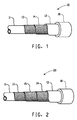
- 'hose' An example of an umbilical thermoplastic hose (hereinafter called 'hose') is shown, generally, at 10 in Fig. 1 .
- the hose can have a coupling 16 attached to both ends.
- the hose comprises a thermoplastic polymeric inner liner 11 and a thermoplastic polymeric outer cover 12. Located between the liner and cover are two fibrous reinforcement layers, a first fibrous layer 13 and a second fibrous layer 14.
- 'Hydraulic' embodiments of the hose must resist internal hydrostatic pressure only, and liner 11 is the innermost layer.
- 'HCR' (High Collapse Resistance) embodiments of a hose must withstand both internal and external hydrostatic pressure, and contain an interlocking stainless steel carcass, not shown, as the innermost component.
- the present invention pertains to fibrous reinforcing layers and applies to both 'hydraulic' and 'HCR' hoses.
- Fig. 2 shows at 20 another embodiment of a hose comprising an intermediate fibrous reinforcement layer 15 located between the first fibrous layer 13 and the second fibrous layer 14.
- Suitable inner liner hose materials include aliphatic polyamide or polyvinylidenefluoride.
- a suitable polyamide is Nylon 11.
- Suitable hose outer cover materials include polyethylene, polyurethane, polyethylene, polypropylene, and aliphatic polyamide.
- a suitable polyamide is Nylon 12.
- the hose comprises a plurality of fibrous reinforcement layers as is shown at 13-14 in Fig. 1 and at 13-15 in Fig. 2 .
- the layers are in the form of a braided fabric, a woven fabric, or a unidirectional fabric.
- a braided fabric is formed by plaiting several strands of fibrous yarn. The yarns are interlaced diagonally to the axial direction of the hose.
- a woven fabric comprises warp and fill yarns, interlaced orthogonally to each other - the warp yarns being parallel to the fabric production direction.
- the woven fabric can be a plain weave, crowfoot weave, basket weave, satin weave, twill weave, unbalanced weave, or any other weave style.
- the reinforcement layer yarns comprise a plurality of continuous filaments.
- the terms fiber and filament may be used interchangeably.
- continuous is meant that the fibers have a high length-to-diameter ratio.
- a bobbin of continuous filament yarn has a length of several thousand meters. A typical filament diameter is about 0.015 mm.
- the continuous filament yarns may be twisted or entangled. Twisting is the process of combining two or more singles yarns into a plied yarn or cord.
- the twist level as described by a twist multiplier ranges from zero to 2.5.
- twist multiplier is as defined in ASTM D123-12.
- An entangled yarn or cord is one in which at least two single yarns are intermixed with each other without adding twist or otherwise disturbing the parallel relationship of the combined filaments. This is also known as comingling or compacting. Twisting and entangling are well known terms in the textile art.
- the reinforcement layer yarns have a tenacity of at least 13 grams per dtex. In some embodiments, the yarn tenacity is at least 18 grams per dtex or even 25 grams per dtex.
- the yarns also have an initial modulus of at least 550 grams per dtex or even 750 grams per dtex. In some embodiments, the yarn modulus is at least 900 grams per dtex.
- the hose comprises at least one first fibrous reinforcement layer and at least one second fibrous reinforcement layer, wherein, the continuous filament yarns of the at least one second fibrous reinforcement layer have a yarn modulus greater than the continuous filament yarn modulus of the at least one first fibrous reinforcement.
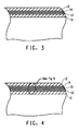
- Fig. 3 shows a hose construction comprising at least one first fibrous reinforcement layer 13 and at least one second fibrous reinforcement layer 14 located between a liner 11 and a cover 12. The yarns of the at least one first fibrous reinforcement layer 13 have a lower modulus than the yarns of the at least one second fibrous reinforcement layer 14.
- Fig. 4 depicts another embodiment of this invention in which at least one intermediate fibrous reinforcement layer 15 is positioned between the at least one first fibrous reinforcement layer 13 and the at least one second fibrous reinforcement layer 14.
- the continuous filament yarns of any at least one intermediate fibrous reinforcement layer have a yarn modulus greater than the continuous filament yarn modulus of the at least one first fibrous reinforcement layer and less than the yarn modulus of the continuous filament yarns of the at least one second fibrous reinforcement layer.
- first fibrous reinforcement layers There may be a plurality of first fibrous reinforcement layers, but the yarn modulus of all yarns comprising the plurality of first reinforcement layers must be the same.
- any one intermediate fibrous reinforcement layer must have a yarn modulus greater than the yarn modulus of the continuous filament yarns of the at least one first fibrous reinforcement layer and less than the yarn modulus of the continuous filament yarns of the at least one second fibrous reinforcement layer.
- Intermediate fibrous reinforcement layers may comprise layers having the same or different moduli.
- the yarns within a layer may have different moduli or all the yarns within one layer may have the same modulus but the moduli between layers may be different.
- a plurality of intermediate fibrous reinforcement layers 15 comprise yarns of a different modulus, the layers must be positioned such that the yarn modulus of an at least one intermediate fibrous layer is no less than yarn modulus of any other at least one intermediate fibrous reinforcement layer positioned closer to the at least one first layer 13.
- Fig. 5 Layers 11 and 12 are as previously stated.
- Fig. 5 shows one first reinforcement layer 13 and two second reinforcement layers 14a and 14b.
- a plurality of intermediate fibrous reinforcement layers are shown as 15a, 15b and 15c.
- the yarns of the first reinforcement layer 13 have the lowest modulus of any reinforcement layer.
- the two layers 14a and 14b of the second reinforcement layer have a higher yarn modulus than the modulus of yarns in layers 15a-15c and 13.
- the yarn modulus of 14a is the same as that of 14b.
- the yarn modulus of the intermediate reinforcement layers 15a, 15b and 15c may all be the same or different with the proviso previously disclosed defining the yarn modulus relationship with the yarns of layers 13 and 14.
- Layer 15a has the highest yarn modulus of layers 15a-15c.
- Layer 15b may have the same or lower yarn modulus than that of 15a or alternatively may have the same or higher modulus than layer 15c.
- the moduli (E) of layers 15a-15c are in the order of E15a ⁇ E15b ⁇ E15c.
- the continuous filament yarns are made of aromatic polyamide or aromatic co-polyamide.
- a preferred aromatic polyamide is p-aramid that is available from E.I. du Pont de Nemours and Company, Wilmington, DE under the tradename Kevlar® or from Teijin Aramid, Conyers, GA under the tradenames Twaron® and Technora®.
- Some suitable fibers are listed in Table 1.
- Table 1 Yarn Type Tensile Modulus (g/dtex) Tenacity (g/dtex) Kevlar® 119 500 27 Kevlar® 29 667 25 Kevlar® 29AP 667 29 Kevlar® 129 833 30 Kevlar® 49 944 24 Kevlar® 49AP 1033 25
- para-aramid filaments means filaments made of para-aramid polymer.
- aramid means a polyamide wherein at least 85% of the amide (-CONH-) linkages are attached directly to two aromatic rings.
- Suitable aramid fibers are described in Man-Made Fibres - Science and Technology, Volume 2, in the section titled Fibre-Forming Aromatic Polyamides, page 297, W. Black et al., Interscience Publishers, 1968 .
- Aramid fibers and their production are, also, disclosed in U.S. Patents 3,767,756 ; 4,172,938 ; 3,869,429 ; 3,869,430 ; 3,819,587 ; 3,673,143 ; 3,354,127 ; and 3,094,511 .
- the preferred para-aramid is poly (p-phenylene terephthalamide) which is called PPD-T.
- PPD-T is meant the homopolymer resulting from mole-for-mole polymerization of p-phenylene diamine and terephthaloyl chloride and, also, copolymers resulting from incorporation of small amounts of other diamines with the p-phenylene diamine and of small amounts of other diacid chlorides with the terephthaloyl chloride.
- PPD-T means copolymers resulting from incorporation of other aromatic diamines and other aromatic diacid chlorides such as, for example, 2, 6-naphthaloyl chloride or chloro- or dichloroterephthaloyl chloride or 3, 4'-diaminodiphenylether.
- the yarns of the fiber - resin composite consist solely of PPD-T filaments; in some preferred embodiments, the layers in the fiber - resin composite consist solely of PPD-T yarns; in other words, in some preferred embodiments all filaments in the fiber - resin composite are PPD-T filaments.
- Additives can be used with the aramid and it has been found that up to as much as 10 percent or more, by weight, of other polymeric material can be blended with the aramid.
- Copolymers can be used having as much as 10 percent or more of other diamine substituted for the diamine of the aramid or as much as 10 percent or more of other diacid chloride substituted for the diacid chloride or the aramid.
- Another suitable fiber is one based on aromatic copolyamide prepared by reaction of terephthaloyl chloride (TPA) with a 50/50 mole ratio of p -phenylene diamine (PPD) and 3, 4'-diaminodiphenyl ether (DPE).
- TPA terephthaloyl chloride
- PPD p -phenylene diamine
- DPE 3, 4'-diaminodiphenyl ether
- Yet another suitable fiber is that formed by polycondensation reaction of two diamines, p-phenylene diamine and 5-amino-2-(p-aminophenyl) benzimidazole with terephthalic acid or anhydrides or acid chloride derivatives of these monomers.
- the multilayer hose as described above can be assembled with end couplings and other fittings into an umbilical suitable for use in deep-sea and other applications.
- Test Method A is similar to ISO test method 1402:2009, Edition 4, dated 30 November 2009 .
- One end of the hose to be tested is connected to a pressure transducer capable of recording 100,000 psi.
- that end is connected to a vent valve to evacuate air from the hose prior to internal pressurization.
- the other hose end is connected to a MaxPro Technologies High Pressure water pump capable of delivering up to 100,000 psi pressure.
- the hose is placed on a track of linear bearings to permit axial contraction and growth.
- the hydrostatic pump is turned on and the vent valve left open to fill the hose with water and vent all air from the system. With the air evacuated, the vent valve is closed and the hose cycled 5 times from 1000 psi to 10,000 psi to pre-strain the hose liner and reinforcing components. After the fifth cycle, the pressure is allowed to decrease to 100 psi, at which point pressure is increased at a rate of 500-600 psi per second until the hose fails.
- Examples of the inventive concept were tested in a 12.7 mm (0.5 inch) internal diameter HCR hose. Examples prepared according to the current invention are indicated by numerical values. Control or Comparative Examples are indicated by letters.
- Each hose comprised, in order, an interlocking carcass, a thermoplastic inner liner, a first fibrous reinforcement braid layer, a second fibrous reinforcement braid layer, and a thermoplastic outer cover.
- the interlocking carcass which is in commercial use, was of stainless steel, had an inner diameter of 12.7 mm and was 1.6 mm thick.
- the inner liner which is also in commercial use, was of Nylon 11, had an inner diameter of 15.9 mm and was 1.3 mm thick.
- the outer cover which is also in commercial use, was of polyurethane and was extruded above the second reinforcement layer.
- the first and second fibrous reinforcement layers were both braids comprising para-aramid Kevlar® 129 yarn from DuPont, having 24 braid plates with each braid plate having a linear density of 32000dtex (28800 denier), a tenacity of 30 g/dtex (27.5 gpd) and a modulus of 833 g/dtex (750 gpd).
- the first fibrous reinforcement layer was a braid comprising para-aramid Kevlar® 119 yarn from DuPont, having 24 braid plates with each braid plate having a linear density of of 20000 dtex ( 18000 denier), a tenacity of 27 g/dtex (24.3 gpd) and a modulus of 500 g/dtex (450 gpd).
- the second fibrous reinforcement layer was a braid comprising para-aramid Kevlar® 49AP yarn from DuPont, having 24 braid plates with each braid plate having a linear density of 18930 dtex (17040 denier), a tenacity of 25 g/dtex (22.5 gpd), and a modulus of 1033 g/dtex (930 gpd).
- Example 1 The hoses of Example 1 and Comparative Example A were subjected to a pressure burst test according to ISO test method 1402:2009, Edition 4, dated 30 November 2009 .
- the test results are shown in Table 3. It is seen that the burst pressure for hose Example 1 exceeds the burst pressure for hose Example A by four percent.
- the first fibrous reinforcement layer was a braid comprising para-aramid Kevlar® 49AP yarn from DuPont, having 24 braid plates with each braid plate having a linear density of 12624 dtex (11360 denier), a tenacity of 25 g/dtex (22.5 gpd) and a modulus of 1033 g/dtex.
- the second fibrous reinforcement layer was a braid comprising para-aramid Kevlar® 49AP yarn from DuPont, having 24 braid plates with each braid plate having a linear density of 18930 dtex (17040 denier), a tenacity of 25 g/dtex (22.5 gpd) and a modulus of 1033 g/dtex.
- the first fibrous reinforcement layer was braid comprising para-aramid Kevlar® 119 yarn from DuPont having 24 braid plates with each braid plate having a linear density of 13360 dtex (12000 denier), a tenacity of 27 g/dtex (24.3 gpd) and a modulus of 500 g/dtex (450 gpd).
- the second fibrous reinforcement layer was a braid comprising para-aramid Kevlar® 49AP yarn from DuPont, having 24 braid plates with each braid plate having a linear density of 18930 dtex (17040 denier), a tenacity of 25 g/dtex (22.5 gpd) and a modulus of 1033 g/dtex.
- Example 2 The hoses of Example 2 and Comparative Example B were subjected to a pressure burst test according to Test Method A previously described. The test results are shown in Table 3. It is seen that the burst pressure for hose Example 2 exceeds the burst pressure for hose Example B by nineteen percent.
- Table 3 Yarn Modulus Layer 1 (g/dtex) Yarn Modulus Layer 2 (g/dtex) Burst Pressure (MPa) Comparative A 855 855 233 Example 1 705 1033 243 Comparative B 1167 1033 148 Example 2 705 1033 176
- Example 1 in which the second layer yarn modulus is greater than the first layer yarn modulus showed a 4 percent improvement in burst pressure when compared with Comparative Example A in which the second layer yarn modulus is not greater than the first layer yarn modulus.
- Example 2 in which the second layer yarn modulus is greater than the first layer yarn modulus showed an 18 percent improvement in burst pressure when compared with Comparative Example B in which the second layer yarn modulus is not greater than the first layer yarn modulus.
Landscapes
- Engineering & Computer Science (AREA)
- General Engineering & Computer Science (AREA)
- Mechanical Engineering (AREA)
- Textile Engineering (AREA)
- Rigid Pipes And Flexible Pipes (AREA)
- Laminated Bodies (AREA)
Abstract
Description
- This invention pertains to a multilayer reinforced hose that is particularly suitable for use in a service umbilical.
- Hoses used in umbilicals contain layers of reinforcing fibers braided over a thermoplastic polymer liner. Umbilicals provide the connecting medium for electrical, hydraulic, chemical injection, and fiber optic connections between topside facilities (ocean and sea surface structures, for example) and various subsea items. A common cause of hose failure is reinforcement failure. There is a need, therefore, to provide solutions that can extend the useful life of reinforcement layers in an umbilical hose.
- This invention pertains to a multilayer hose comprising in order:
- (i) a thermoplastic inner liner,
- (ii) at least one first fibrous reinforcement layer comprising continuous filament yarns having a yarn tenacity of at least 13 grams per dtex,
- (iii) at least one second fibrous reinforcement layer comprising continuous filament yarns having a yarn tenacity of at least 13 grams per dtex, and
- (iv) a thermoplastic outer cover,
- The invention further pertains to a multilayer hose comprising in order:
- (i) a thermoplastic inner liner,
- (ii) at least one first fibrous reinforcement layer comprising continuous filament yarns having a yarn tenacity of at least 13 grams per dtex,
- (iii) at least one second fibrous reinforcement layer comprising continuous filament yarns having a yarn tenacity of at least 13 grams per dtex,
- (iv) at least one intermediate fibrous reinforcement layer comprising continuous filament yarns having a yarn tenacity of at least 13 grams per dtex positioned between the at least one first and the at least one second fibrous reinforcement layers, and
- (v) a thermoplastic outer cover,
wherein- (a) the continuous filament yarns of any at least one intermediate fibrous reinforcement layer have a yarn modulus greater than the yarn modulus of the continuous filament yarns of the at least one first fibrous reinforcement layer and no less than the yarn modulus of the continuous filament yarns of the at least one second fibrous reinforcement layer, and
- (b) the continuous filament yarns of any at least one intermediate fibrous layer have yarn modulus no less than yarn modulus of any other at least one intermediate fibrous reinforcement layer positioned closer to the at least one first layer.
-
-
Figure 1 depicts a cutaway perspective of one embodiment of a hose comprising two fibrous reinforcement layers. -
Figure 2 depicts a cutaway perspective of a hose comprising three fibrous reinforcement layers. -
Figure 3 is a half-sectional longitudinal view of a hose comprising two fibrous reinforcement layers. -
Figure 4 is a half-sectional longitudinal view through a hose comprising three fibrous reinforcement layers. -
Figure 5 is a half-sectional longitudinal view through another embodiment of a hose. - An example of an umbilical thermoplastic hose (hereinafter called 'hose') is shown, generally, at 10 in
Fig. 1 . The hose can have acoupling 16 attached to both ends. The hose comprises a thermoplastic polymericinner liner 11 and a thermoplastic polymericouter cover 12. Located between the liner and cover are two fibrous reinforcement layers, a firstfibrous layer 13 and a secondfibrous layer 14. 'Hydraulic' embodiments of the hose must resist internal hydrostatic pressure only, andliner 11 is the innermost layer. 'HCR' (High Collapse Resistance) embodiments of a hose must withstand both internal and external hydrostatic pressure, and contain an interlocking stainless steel carcass, not shown, as the innermost component. The present invention pertains to fibrous reinforcing layers and applies to both 'hydraulic' and 'HCR' hoses. -
Fig. 2 shows at 20 another embodiment of a hose comprising an intermediatefibrous reinforcement layer 15 located between the firstfibrous layer 13 and the secondfibrous layer 14. - Suitable inner liner hose materials include aliphatic polyamide or polyvinylidenefluoride. A suitable polyamide is Nylon 11.
- Suitable hose outer cover materials include polyethylene, polyurethane, polyethylene, polypropylene, and aliphatic polyamide. A suitable polyamide is Nylon 12.
- The hose comprises a plurality of fibrous reinforcement layers as is shown at 13-14 in
Fig. 1 and at 13-15 inFig. 2 . Preferably, the layers are in the form of a braided fabric, a woven fabric, or a unidirectional fabric. A braided fabric is formed by plaiting several strands of fibrous yarn. The yarns are interlaced diagonally to the axial direction of the hose. - A woven fabric comprises warp and fill yarns, interlaced orthogonally to each other - the warp yarns being parallel to the fabric production direction. The woven fabric can be a plain weave, crowfoot weave, basket weave, satin weave, twill weave, unbalanced weave, or any other weave style.
- All unidirectional fabric reinforcement yarns are aligned in the direction parallel to the fabric production direction. There may be a few lightweight yarns in the fill direction used to help maintain the alignment of the reinforcement yarns. When woven or unidirectional fabrics are used, the fabric width is preferably less than 25 mm, that is to say that the fabrics are considered to be narrow fabrics. The reinforcement layer yarns comprise a plurality of continuous filaments. The terms fiber and filament may be used interchangeably. By continuous, is meant that the fibers have a high length-to-diameter ratio. Typically, a bobbin of continuous filament yarn has a length of several thousand meters. A typical filament diameter is about 0.015 mm.
- In some embodiments, the continuous filament yarns may be twisted or entangled. Twisting is the process of combining two or more singles yarns into a plied yarn or cord. In some embodiments, the twist level as described by a twist multiplier ranges from zero to 2.5. As used here, twist multiplier is as defined in ASTM D123-12. An entangled yarn or cord is one in which at least two single yarns are intermixed with each other without adding twist or otherwise disturbing the parallel relationship of the combined filaments. This is also known as comingling or compacting. Twisting and entangling are well known terms in the textile art.
- The reinforcement layer yarns have a tenacity of at least 13 grams per dtex. In some embodiments, the yarn tenacity is at least 18 grams per dtex or even 25 grams per dtex. The yarns also have an initial modulus of at least 550 grams per dtex or even 750 grams per dtex. In some embodiments, the yarn modulus is at least 900 grams per dtex.
- A requirement of one embodiment of this invention is that the hose comprises at least one first fibrous reinforcement layer and at least one second fibrous reinforcement layer, wherein, the continuous filament yarns of the at least one second fibrous reinforcement layer have a yarn modulus greater than the continuous filament yarn modulus of the at least one first fibrous reinforcement.
Fig. 3 shows a hose construction comprising at least one firstfibrous reinforcement layer 13 and at least one secondfibrous reinforcement layer 14 located between aliner 11 and acover 12. The yarns of the at least one firstfibrous reinforcement layer 13 have a lower modulus than the yarns of the at least one secondfibrous reinforcement layer 14. -
Fig. 4 depicts another embodiment of this invention in which at least one intermediatefibrous reinforcement layer 15 is positioned between the at least one firstfibrous reinforcement layer 13 and the at least one secondfibrous reinforcement layer 14. In this construction, the continuous filament yarns of any at least one intermediate fibrous reinforcement layer have a yarn modulus greater than the continuous filament yarn modulus of the at least one first fibrous reinforcement layer and less than the yarn modulus of the continuous filament yarns of the at least one second fibrous reinforcement layer. - There may be a plurality of first fibrous reinforcement layers, but the yarn modulus of all yarns comprising the plurality of first reinforcement layers must be the same.
- Similarly, there may be a plurality of second fibrous reinforcement layers, but the yarn modulus of all yarns comprising the plurality of second reinforcement layers must be the same.
- In a like manner, there may be a plurality of intermediate fibrous reinforcement layers, but the yarns of any one intermediate fibrous reinforcement layer must have a yarn modulus greater than the yarn modulus of the continuous filament yarns of the at least one first fibrous reinforcement layer and less than the yarn modulus of the continuous filament yarns of the at least one second fibrous reinforcement layer.
- Intermediate fibrous reinforcement layers may comprise layers having the same or different moduli. The yarns within a layer may have different moduli or all the yarns within one layer may have the same modulus but the moduli between layers may be different. If a plurality of intermediate fibrous reinforcement layers 15 comprise yarns of a different modulus, the layers must be positioned such that the yarn modulus of an at least one intermediate fibrous layer is no less than yarn modulus of any other at least one intermediate fibrous reinforcement layer positioned closer to the at least one
first layer 13. As an example of this, refer toFig. 5 .Layers Fig. 5 shows onefirst reinforcement layer 13 and two second reinforcement layers 14a and 14b. A plurality of intermediate fibrous reinforcement layers are shown as 15a, 15b and 15c. In the embodiment ofFig. 5 , the yarns of thefirst reinforcement layer 13 have the lowest modulus of any reinforcement layer. The twolayers 14a and 14b of the second reinforcement layer have a higher yarn modulus than the modulus of yarns in layers 15a-15c and 13. The yarn modulus of 14a is the same as that of 14b.The yarn modulus of theintermediate reinforcement layers layers Layer 15b may have the same or lower yarn modulus than that of 15a or alternatively may have the same or higher modulus thanlayer 15c. In other words, the moduli (E) of layers 15a-15c are in the order of E15a ≥ E15b ≥ E15c. - Preferably, the continuous filament yarns are made of aromatic polyamide or aromatic co-polyamide. A preferred aromatic polyamide is p-aramid that is available from E.I. du Pont de Nemours and Company, Wilmington, DE under the tradename Kevlar® or from Teijin Aramid, Conyers, GA under the tradenames Twaron® and Technora®. Some suitable fibers are listed in Table 1.
Table 1 Yarn Type Tensile Modulus (g/dtex) Tenacity (g/dtex) Kevlar® 119 500 27 Kevlar® 29 667 25 Kevlar® 29AP 667 29 Kevlar® 129 833 30 Kevlar® 49 944 24 Kevlar® 49AP 1033 25 - As used herein, the term para-aramid filaments means filaments made of para-aramid polymer. The term aramid means a polyamide wherein at least 85% of the amide (-CONH-) linkages are attached directly to two aromatic rings. Suitable aramid fibers are described in Man-Made Fibres - Science and Technology, Volume 2, in the section titled Fibre-Forming Aromatic Polyamides, page 297, W. Black et al., Interscience Publishers, 1968. Aramid fibers and their production are, also, disclosed in
U.S. Patents 3,767,756 ;4,172,938 ;3,869,429 ;3,869,430 ;3,819,587 ;3,673,143 ;3,354,127 ; and3,094,511 . - The preferred para-aramid is poly (p-phenylene terephthalamide) which is called PPD-T. By PPD-T is meant the homopolymer resulting from mole-for-mole polymerization of p-phenylene diamine and terephthaloyl chloride and, also, copolymers resulting from incorporation of small amounts of other diamines with the p-phenylene diamine and of small amounts of other diacid chlorides with the terephthaloyl chloride. As a general rule, other diamines and other diacid chlorides can be used in amounts up to as much as about 10 mole percent of the p-phenylene diamine or the terephthaloyl chloride, or perhaps slightly higher, provided only that the other diamines and diacid chlorides have no reactive groups which interfere with the polymerization reaction. PPD-T, also, means copolymers resulting from incorporation of other aromatic diamines and other aromatic diacid chlorides such as, for example, 2, 6-naphthaloyl chloride or chloro- or dichloroterephthaloyl chloride or 3, 4'-diaminodiphenylether. In some preferred embodiments, the yarns of the fiber - resin composite consist solely of PPD-T filaments; in some preferred embodiments, the layers in the fiber - resin composite consist solely of PPD-T yarns; in other words, in some preferred embodiments all filaments in the fiber - resin composite are PPD-T filaments.
- Additives can be used with the aramid and it has been found that up to as much as 10 percent or more, by weight, of other polymeric material can be blended with the aramid. Copolymers can be used having as much as 10 percent or more of other diamine substituted for the diamine of the aramid or as much as 10 percent or more of other diacid chloride substituted for the diacid chloride or the aramid.
- Another suitable fiber is one based on aromatic copolyamide prepared by reaction of terephthaloyl chloride (TPA) with a 50/50 mole ratio of p-phenylene diamine (PPD) and 3, 4'-diaminodiphenyl ether (DPE). Yet another suitable fiberis that formed by polycondensation reaction of two diamines, p-phenylene diamine and 5-amino-2-(p-aminophenyl) benzimidazole with terephthalic acid or anhydrides or acid chloride derivatives of these monomers.
-
Table 2 First Reinforcement Layer(s) Intermediate Reinforcement Layer(s) Second Reinforcement Layer(s) Kevlar® 119 Kevlar® 29 Kevlar® 49 Kevlar® 119 (2 layers) None Kevlar® 29 Kevlar® 119 (2 layers) None Kevlar® 129 Kevlar® 119 (2 layers) None Kevlar® 49 Kevlar® 119 None Kevlar® 29 (2 layers) Kevlar® 119 Kevlar® 29 Kevlar® 129 Kevlar® 119 Kevlar® 29 Kevlar® 49 Kevlar® 119 None Kevlar® 129 (2 layers) Kevlar® 119 Kevlar® 129 Kevlar® 49 Kevlar® 119 None Kevlar® 49 (2 layers) Kevlar® 29 (2 layers) None Kevlar® 129 Kevlar® 29 (2 layers) None Kevlar® 49 Kevlar® 29 Kevlar® 129 (2 layers) Kevlar® 49 Kevlar® 29 None Kevlar® 49 (2 layers) Kevlar® 129 (2 layers) None Kevlar® 49 Kevlar® 129 None Kevlar® 49 (2 layers) Kevlar® 119 Kevlar® 29 Kevlar® 49AP Kevlar® 119 Kevlar® 129 Kevlar® 49AP Kevlar® 129 None Kevlar® 49 (2 layers) Kevlar® 119 None Kevlar® 49 Kevlar® 119 Kevlar® 29 (next to 1st layer) Kevlar® 49 Kevlar® 129 (next to 2nd layer) - The multilayer hose as described above can be assembled with end couplings and other fittings into an umbilical suitable for use in deep-sea and other applications.
- Test Method A is similar to ISO test method 1402:2009, Edition 4, dated 30 November 2009. One end of the hose to be tested is connected to a pressure transducer capable of recording 100,000 psi. In addition, that end is connected to a vent valve to evacuate air from the hose prior to internal pressurization. The other hose end is connected to a MaxPro Technologies High Pressure water pump capable of delivering up to 100,000 psi pressure. The hose is placed on a track of linear bearings to permit axial contraction and growth.
- The hydrostatic pump is turned on and the vent valve left open to fill the hose with water and vent all air from the system. With the air evacuated, the vent valve is closed and the hose cycled 5 times from 1000 psi to 10,000 psi to pre-strain the hose liner and reinforcing components. After the fifth cycle, the pressure is allowed to decrease to 100 psi, at which point pressure is increased at a rate of 500-600 psi per second until the hose fails.
- Examples of the inventive concept were tested in a 12.7 mm (0.5 inch) internal diameter HCR hose. Examples prepared according to the current invention are indicated by numerical values. Control or Comparative Examples are indicated by letters.
- Each hose comprised, in order, an interlocking carcass, a thermoplastic inner liner, a first fibrous reinforcement braid layer, a second fibrous reinforcement braid layer, and a thermoplastic outer cover.
- The interlocking carcass, which is in commercial use, was of stainless steel, had an inner diameter of 12.7 mm and was 1.6 mm thick. The inner liner, which is also in commercial use, was of
Nylon 11, had an inner diameter of 15.9 mm and was 1.3 mm thick. The outer cover, which is also in commercial use, was of polyurethane and was extruded above the second reinforcement layer. - In Comparative Example A, the first and second fibrous reinforcement layers were both braids comprising para-aramid Kevlar® 129 yarn from DuPont, having 24 braid plates with each braid plate having a linear density of 32000dtex (28800 denier), a tenacity of 30 g/dtex (27.5 gpd) and a modulus of 833 g/dtex (750 gpd).
- In Example 1, the first fibrous reinforcement layer was a braid comprising para-aramid Kevlar® 119 yarn from DuPont, having 24 braid plates with each braid plate having a linear density of of 20000 dtex ( 18000 denier), a tenacity of 27 g/dtex (24.3 gpd) and a modulus of 500 g/dtex (450 gpd). The second fibrous reinforcement layer was a braid comprising para-aramid Kevlar® 49AP yarn from DuPont, having 24 braid plates with each braid plate having a linear density of 18930 dtex (17040 denier), a tenacity of 25 g/dtex (22.5 gpd), and a modulus of 1033 g/dtex (930 gpd).
- The hoses of Example 1 and Comparative Example A were subjected to a pressure burst test according to ISO test method 1402:2009, Edition 4, dated 30 November 2009. The test results are shown in Table 3. It is seen that the burst pressure for hose Example 1 exceeds the burst pressure for hose Example A by four percent.
- In Comparative Example B, the first fibrous reinforcement layer was a braid comprising para-aramid Kevlar® 49AP yarn from DuPont, having 24 braid plates with each braid plate having a linear density of 12624 dtex (11360 denier), a tenacity of 25 g/dtex (22.5 gpd) and a modulus of 1033 g/dtex. The second fibrous reinforcement layer was a braid comprising para-aramid Kevlar® 49AP yarn from DuPont, having 24 braid plates with each braid plate having a linear density of 18930 dtex (17040 denier), a tenacity of 25 g/dtex (22.5 gpd) and a modulus of 1033 g/dtex.
- In Example 2, the first fibrous reinforcement layer was braid comprising para-aramid Kevlar® 119 yarn from DuPont having 24 braid plates with each braid plate having a linear density of 13360 dtex (12000 denier), a tenacity of 27 g/dtex (24.3 gpd) and a modulus of 500 g/dtex (450 gpd). The second fibrous reinforcement layer was a braid comprising para-aramid Kevlar® 49AP yarn from DuPont, having 24 braid plates with each braid plate having a linear density of 18930 dtex (17040 denier), a tenacity of 25 g/dtex (22.5 gpd) and a modulus of 1033 g/dtex.
- The hoses of Example 2 and Comparative Example B were subjected to a pressure burst test according to Test Method A previously described. The test results are shown in Table 3. It is seen that the burst pressure for hose Example 2 exceeds the burst pressure for hose Example B by nineteen percent.
Table 3 Yarn Modulus Layer 1 (g/dtex) Yarn Modulus Layer 2 (g/dtex) Burst Pressure (MPa) Comparative A 855 855 233 Example 1 705 1033 243 Comparative B 1167 1033 148 Example 2 705 1033 176 - Example 1 in which the second layer yarn modulus is greater than the first layer yarn modulus showed a 4 percent improvement in burst pressure when compared with Comparative Example A in which the second layer yarn modulus is not greater than the first layer yarn modulus.
- Example 2 in which the second layer yarn modulus is greater than the first layer yarn modulus showed an 18 percent improvement in burst pressure when compared with Comparative Example B in which the second layer yarn modulus is not greater than the first layer yarn modulus.
Claims (8)
- A multilayer hose, comprising in order:(i) a thermoplastic inner liner(ii) at least one first fibrous reinforcement layer comprising continuous filament yarns having a yarn tenacity of at least 13 grams per dtex,(iii) at least one second fibrous reinforcement layer comprising continuous filament yarns having a yarn tenacity of at least 13 grams per dtex, and(iv) a thermoplastic outer cover,wherein the continuous filament yarns of the at least one second fibrous reinforcement layer have a yarn modulus greater than the yarn modulus of the continuous filament yarns of the at least one first fibrous reinforcement.
- A multilayer hose, comprising in order:(i) a thermoplastic inner liner,(ii) at least one first fibrous reinforcement layer comprising continuous filament yarns having a yarn tenacity of at least 13 grams per dtex,(iii) at least one second fibrous reinforcement layer comprising continuous filament yarns having a yarn tenacity of at least 13 grams per dtex,(iv) at least one intermediate fibrous reinforcement layer comprising continuous filament yarns having a yarn tenacity of at least 13 grams per dtex positioned between the at least one first and the at least one second fibrous reinforcement layers, and(v) a thermoplastic outer cover,
wherein(a) the continuous filament yarns of any at least one intermediate fibrous reinforcement layer have a yarn modulus greater than the yarn modulus of the continuous filament yarns of the at least one first fibrous reinforcement layer and no less than the yarn modulus of the continuous filament yarns of the at least one second fibrous reinforcement layer, and(b) the continuous filament yarns of any at least one intermediate fibrous layer have yarn modulus no less than yarn modulus of any other at least one intermediate fibrous reinforcement layer positioned closer to the at least one first layer. - The hose of claim 1 or 2, wherein the continuous filament yarns are of aromatic polyamide or aromatic co-polyamide.
- The hose of claim 1 or 2, wherein the continuous filament yarns are twisted or entangled.
- The hose of claim 1 or 2, wherein the first, second and intermediate fibrous reinforcement layers are in the form of a braid, a woven fabric, or a unidirectional fabric.
- The hose of claim 3, wherein the aromatic polyamide is p-aramid.
- The hose of claim 5, wherein the braid, woven fabric, or unidirectional fabric is impregnated with resin.
- An umbilical, comprising the hose of claim 1 or claim 2.
Applications Claiming Priority (1)
| Application Number | Priority Date | Filing Date | Title |
|---|---|---|---|
| US13/925,081 US9115831B2 (en) | 2013-06-24 | 2013-06-24 | Multilayer reinforced hose |
Publications (1)
| Publication Number | Publication Date |
|---|---|
| EP2818314A1 true EP2818314A1 (en) | 2014-12-31 |
Family
ID=50897478
Family Applications (1)
| Application Number | Title | Priority Date | Filing Date |
|---|---|---|---|
| EP14172030.0A Withdrawn EP2818314A1 (en) | 2013-06-24 | 2014-06-11 | Multilayer reinforced hose |
Country Status (3)
| Country | Link |
|---|---|
| US (1) | US9115831B2 (en) |
| EP (1) | EP2818314A1 (en) |
| BR (1) | BR102014015503A2 (en) |
Families Citing this family (8)
| Publication number | Priority date | Publication date | Assignee | Title |
|---|---|---|---|---|
| US10663666B2 (en) * | 2013-12-05 | 2020-05-26 | United States Of America As Represented By The Secretary Of The Navy | Flexible, low profile kink resistant fiber optic splice tension sleeve |
| JP6103088B2 (en) * | 2015-06-09 | 2017-03-29 | 横浜ゴム株式会社 | Hydrogen filling hose |
| CN105546230B (en) * | 2016-02-02 | 2018-05-15 | 浙江鑫宙竹基复合材料科技有限公司 | A kind of stalk bamboo coiled composite tube and preparation method thereof |
| US9964237B2 (en) | 2016-02-25 | 2018-05-08 | Nlb Corp. | Hose shroud |
| CN106117639A (en) * | 2016-06-29 | 2016-11-16 | 中裕软管科技有限公司 | A kind of ultra-high molecular weight polyethylene strengthens big flow conveying high-pressure flexible pipe and manufacture method thereof |
| US10480690B2 (en) * | 2016-09-13 | 2019-11-19 | Eaton Intelligent Power Limited | Fiber reinforced thermoplastic hoses and methods for forming the same |
| JP6988159B2 (en) * | 2017-05-16 | 2022-01-05 | 横浜ゴム株式会社 | High pressure hose |
| US20260101875A1 (en) * | 2024-10-16 | 2026-04-16 | Darryl Kimble | Pet safety collar device |
Citations (14)
| Publication number | Priority date | Publication date | Assignee | Title |
|---|---|---|---|---|
| US3094511A (en) | 1958-11-17 | 1963-06-18 | Du Pont | Wholly aromatic polyamides |
| US3354127A (en) | 1966-04-18 | 1967-11-21 | Du Pont | Aromatic copolyamides |
| US3673143A (en) | 1970-06-24 | 1972-06-27 | Du Pont | Optically anisotropic spinning dopes of polycarbonamides |
| US3767756A (en) | 1972-06-30 | 1973-10-23 | Du Pont | Dry jet wet spinning process |
| US3819587A (en) | 1969-05-23 | 1974-06-25 | Du Pont | Wholly aromatic carbocyclic polycarbonamide fiber having orientation angle of less than about 45{20 |
| US3869429A (en) | 1971-08-17 | 1975-03-04 | Du Pont | High strength polyamide fibers and films |
| US3869430A (en) | 1971-08-17 | 1975-03-04 | Du Pont | High modulus, high tenacity poly(p-phenylene terephthalamide) fiber |
| US3905398A (en) * | 1974-04-23 | 1975-09-16 | Moore & Co Samuel | Composite reinforced hose wherein the reinforcing material is braided aromatic polyamide filaments |
| US4172938A (en) | 1976-06-23 | 1979-10-30 | Teijin Limited | Process for producing polyamides with lactam or urea solvent and CaCl2 |
| US4273160A (en) * | 1977-09-12 | 1981-06-16 | Parker-Hannifin Corporation | High pressure hose |
| US4699178A (en) * | 1985-01-25 | 1987-10-13 | Parker Hannifin Corporation | Low volumetric expansion hose |
| US5499661A (en) * | 1988-03-02 | 1996-03-19 | Institut Francais Du Petrole | Tube comprising composite layers with different modulii of elasticity |
| US20100326558A1 (en) * | 2008-01-11 | 2010-12-30 | Anh Tuan Do | Flexible pipe for conveying hydrocarbons in deep water |
| WO2012172290A1 (en) * | 2011-06-13 | 2012-12-20 | Oceaneering International Services Limited | Improved umbilical with fatigue resistant fibres |
Family Cites Families (13)
| Publication number | Priority date | Publication date | Assignee | Title |
|---|---|---|---|---|
| US4343333A (en) * | 1979-08-27 | 1982-08-10 | Eaton Corporation | Fatigue resistant high pressure hose |
| US4384595A (en) * | 1981-09-14 | 1983-05-24 | Parker-Hannifin Corporation | Hose construction |
| US5052444A (en) * | 1987-04-30 | 1991-10-01 | The Fluorocarbon Company | Reinforced fluid hose having on-bonded tape |
| JPH05163610A (en) * | 1991-12-18 | 1993-06-29 | Teijin Ltd | Aromatic polyamide flat fiber |
| EP0740098B1 (en) * | 1995-04-28 | 1999-10-27 | The Yokohama Rubber Co., Ltd. | Reinforced pressure hose |
| US6179008B1 (en) * | 1996-02-09 | 2001-01-30 | The Yokohama Rubber Co., Ltd. | Thermoplastic elastomer composition, process for the preparation there of, hose made by using the composition, and process for the production thereof |
| JP4277967B2 (en) * | 1999-04-16 | 2009-06-10 | 横浜ゴム株式会社 | High pressure rubber hose and manufacturing method thereof |
| JP2005114135A (en) * | 2003-10-10 | 2005-04-28 | Toyoda Gosei Co Ltd | Reinforced hose |
| US7572745B2 (en) * | 2006-09-26 | 2009-08-11 | The Gates Corporation | Fluid transfer hose reinforced with hybrid yarn |
| US7757517B2 (en) * | 2007-08-23 | 2010-07-20 | Federal-Mogul Powertrain, Inc. | Protective sleeve with knitted opening and method on construction |
| US8955552B2 (en) * | 2009-07-24 | 2015-02-17 | Parker-Hannifin Corporation | Fire resistant hose assembly |
| CN102561076B (en) * | 2010-12-16 | 2015-02-25 | 杜邦公司 | Composite rope with high breaking force and high elongation at break and relevant enhanced products and use |
| EP3052846A1 (en) * | 2013-10-02 | 2016-08-10 | E. I. du Pont de Nemours and Company | Multilayer reinforced hose |
-
2013
- 2013-06-24 US US13/925,081 patent/US9115831B2/en not_active Expired - Fee Related
-
2014
- 2014-06-11 EP EP14172030.0A patent/EP2818314A1/en not_active Withdrawn
- 2014-06-24 BR BR102014015503A patent/BR102014015503A2/en not_active IP Right Cessation
Patent Citations (14)
| Publication number | Priority date | Publication date | Assignee | Title |
|---|---|---|---|---|
| US3094511A (en) | 1958-11-17 | 1963-06-18 | Du Pont | Wholly aromatic polyamides |
| US3354127A (en) | 1966-04-18 | 1967-11-21 | Du Pont | Aromatic copolyamides |
| US3819587A (en) | 1969-05-23 | 1974-06-25 | Du Pont | Wholly aromatic carbocyclic polycarbonamide fiber having orientation angle of less than about 45{20 |
| US3673143A (en) | 1970-06-24 | 1972-06-27 | Du Pont | Optically anisotropic spinning dopes of polycarbonamides |
| US3869430A (en) | 1971-08-17 | 1975-03-04 | Du Pont | High modulus, high tenacity poly(p-phenylene terephthalamide) fiber |
| US3869429A (en) | 1971-08-17 | 1975-03-04 | Du Pont | High strength polyamide fibers and films |
| US3767756A (en) | 1972-06-30 | 1973-10-23 | Du Pont | Dry jet wet spinning process |
| US3905398A (en) * | 1974-04-23 | 1975-09-16 | Moore & Co Samuel | Composite reinforced hose wherein the reinforcing material is braided aromatic polyamide filaments |
| US4172938A (en) | 1976-06-23 | 1979-10-30 | Teijin Limited | Process for producing polyamides with lactam or urea solvent and CaCl2 |
| US4273160A (en) * | 1977-09-12 | 1981-06-16 | Parker-Hannifin Corporation | High pressure hose |
| US4699178A (en) * | 1985-01-25 | 1987-10-13 | Parker Hannifin Corporation | Low volumetric expansion hose |
| US5499661A (en) * | 1988-03-02 | 1996-03-19 | Institut Francais Du Petrole | Tube comprising composite layers with different modulii of elasticity |
| US20100326558A1 (en) * | 2008-01-11 | 2010-12-30 | Anh Tuan Do | Flexible pipe for conveying hydrocarbons in deep water |
| WO2012172290A1 (en) * | 2011-06-13 | 2012-12-20 | Oceaneering International Services Limited | Improved umbilical with fatigue resistant fibres |
Non-Patent Citations (2)
| Title |
|---|
| "ISO test method 1402:2009", 30 November 2009 |
| W. BLACK ET AL.: "Man-Made Fibres - Science and Technology", vol. 2, 1968, INTERSCIENCE PUBLISHERS, article "Fibre-Forming Aromatic Polyamides", pages: 297 |
Also Published As
| Publication number | Publication date |
|---|---|
| BR102014015503A2 (en) | 2016-08-02 |
| US20140373962A1 (en) | 2014-12-25 |
| US9115831B2 (en) | 2015-08-25 |
Similar Documents
| Publication | Publication Date | Title |
|---|---|---|
| EP2818314A1 (en) | Multilayer reinforced hose | |
| US9188258B2 (en) | Multilayer reinforced hose | |
| US8709562B2 (en) | Hybrid fiber constructions to mitigate creep in composites | |
| TW536617B (en) | Penetration-resistant material comprising fabric with high linear density ratio of two sets of threads | |
| EP2867394B1 (en) | Hybrid tank wall for high performance crash resistant tanks | |
| EP2416953B1 (en) | Ballistic resistant armor articles | |
| AU2008299662A1 (en) | Hose | |
| US8796163B2 (en) | Multi layer fabrics for structural applications having woven and unidirectional portions and methods of fabricating same | |
| KR101290449B1 (en) | Fiber network layers and flexible penetration resistant articles comprising same | |
| AU2012255184A1 (en) | A flexible unbonded pipe | |
| US9377137B2 (en) | Bonded high-pressure rubber hose, particularly for conveying gaseous media | |
| AU2012250336A1 (en) | A flexible unbonded pipe | |
| CN105745511B (en) | Composite and the bulletproof armor product comprising the composite | |
| CA2673061A1 (en) | Flexible ballistic fabric and articles made therefrom | |
| US20130071642A1 (en) | Fabric assembly suitable for resisting ballistic objects and method of manufacture | |
| US7794813B2 (en) | Tubular composite structures | |
| US20100203273A1 (en) | Anti-chafe cable cover | |
| US20170292639A1 (en) | Carbon Fiber Composite Reinforcement With Circumferential And Axial Interlocking | |
| KR20190013817A (en) | Intrinsically viscous material |
Legal Events
| Date | Code | Title | Description |
|---|---|---|---|
| PUAI | Public reference made under article 153(3) epc to a published international application that has entered the european phase |
Free format text: ORIGINAL CODE: 0009012 |
|
| 17P | Request for examination filed |
Effective date: 20140611 |
|
| AK | Designated contracting states |
Kind code of ref document: A1 Designated state(s): AL AT BE BG CH CY CZ DE DK EE ES FI FR GB GR HR HU IE IS IT LI LT LU LV MC MK MT NL NO PL PT RO RS SE SI SK SM TR |
|
| AX | Request for extension of the european patent |
Extension state: BA ME |
|
| R17P | Request for examination filed (corrected) |
Effective date: 20150630 |
|
| RBV | Designated contracting states (corrected) |
Designated state(s): AL AT BE BG CH CY CZ DE DK EE ES FI FR GB GR HR HU IE IS IT LI LT LU LV MC MK MT NL NO PL PT RO RS SE SI SK SM TR |
|
| TPAC | Observations filed by third parties |
Free format text: ORIGINAL CODE: EPIDOSNTIPA |
|
| 17Q | First examination report despatched |
Effective date: 20170317 |
|
| STAA | Information on the status of an ep patent application or granted ep patent |
Free format text: STATUS: THE APPLICATION HAS BEEN WITHDRAWN |
|
| 18W | Application withdrawn |
Effective date: 20170511 |