EP2818285A1 - Boom utilized in a geometric end effector system - Google Patents
Boom utilized in a geometric end effector system Download PDFInfo
- Publication number
- EP2818285A1 EP2818285A1 EP14174630.5A EP14174630A EP2818285A1 EP 2818285 A1 EP2818285 A1 EP 2818285A1 EP 14174630 A EP14174630 A EP 14174630A EP 2818285 A1 EP2818285 A1 EP 2818285A1
- Authority
- EP
- European Patent Office
- Prior art keywords
- boom
- end effector
- carbon fiber
- anchor mount
- feedback mechanism
- Prior art date
- Legal status (The legal status is an assumption and is not a legal conclusion. Google has not performed a legal analysis and makes no representation as to the accuracy of the status listed.)
- Withdrawn
Links
Images

Classifications
-
- B—PERFORMING OPERATIONS; TRANSPORTING
- B25—HAND TOOLS; PORTABLE POWER-DRIVEN TOOLS; MANIPULATORS
- B25J—MANIPULATORS; CHAMBERS PROVIDED WITH MANIPULATION DEVICES
- B25J13/00—Controls for manipulators
- B25J13/08—Controls for manipulators by means of sensing devices, e.g. viewing or touching devices
- B25J13/085—Force or torque sensors
-
- B—PERFORMING OPERATIONS; TRANSPORTING
- B25—HAND TOOLS; PORTABLE POWER-DRIVEN TOOLS; MANIPULATORS
- B25J—MANIPULATORS; CHAMBERS PROVIDED WITH MANIPULATION DEVICES
- B25J9/00—Program-controlled manipulators
- B25J9/0009—Constructional details, e.g. manipulator supports, bases
- B25J9/0012—Constructional details, e.g. manipulator supports, bases making use of synthetic construction materials, e.g. plastics, composites
-
- B—PERFORMING OPERATIONS; TRANSPORTING
- B25—HAND TOOLS; PORTABLE POWER-DRIVEN TOOLS; MANIPULATORS
- B25J—MANIPULATORS; CHAMBERS PROVIDED WITH MANIPULATION DEVICES
- B25J15/00—Gripping heads and other end effectors
- B25J15/0052—Gripping heads and other end effectors multiple gripper units or multiple end effectors
- B25J15/0061—Gripping heads and other end effectors multiple gripper units or multiple end effectors mounted on a modular gripping structure
-
- B—PERFORMING OPERATIONS; TRANSPORTING
- B25—HAND TOOLS; PORTABLE POWER-DRIVEN TOOLS; MANIPULATORS
- B25J—MANIPULATORS; CHAMBERS PROVIDED WITH MANIPULATION DEVICES
- B25J18/00—Arms
-
- B—PERFORMING OPERATIONS; TRANSPORTING
- B25—HAND TOOLS; PORTABLE POWER-DRIVEN TOOLS; MANIPULATORS
- B25J—MANIPULATORS; CHAMBERS PROVIDED WITH MANIPULATION DEVICES
- B25J15/00—Gripping heads and other end effectors
Definitions
- the present disclosure relates to geometric end effector systems used on a robot and, more particularly, to a boom end effector that has integral sensing technology.
- End effectors for use in assembly systems have been known in the prior art for many years.
- devices are used for holding and placing components and parts in a specified place so that a manufacturing, finishing or other intermediate step can be performed on the product being assembled or worked upon.
- These automated assembly systems generally employ many robots that minimize or eliminate the need for manual intervention, thus reducing the cost to the manufacturer of the labor and parts involved.
- the components used and made in such automated systems are typically made or moved by a robot via an arm or wrist all of which are well known methods in the prior art. Some of these methods may include having an end effector attached to the end of a robot arm and acquires a particular part.
- the end effector then either releases the part during the work or holds the part steady in a pre-specified position during the actual operation on the part.
- Other methods include using the robot arm or wrist to hold a tool to actually perform work on a part that is being held by other robots or other components in predetermined positions.
- the present disclosure provides the art with such a device.
- the present disclosure provides electric feedback as to the status of the jig, fixture or end effector built into the system.
- the boom enables jigs, fixtures or end effectors to become an add-on system capable of processing whether or not the operations are being conducted satisfactorily or if the operation is not normal.
- a boom comprises a cylindrical body including a coupling flange at each end.
- the body is manufactured from a carbon fiber material.
- an electronic feedback mechanism is embedded into the carbon fiber.
- the electronic feedback mechanism may be a simple electronic strain gauge.
- the feedback mechanism may include a fiber optic cable woven into the carbon fiber weave.
- a geometric end effector system comprises a platform with a frame secured to the platform.
- a plurality of bases is arranged at predetermined positions on the frame.
- An anchor mount is secured to at least one of the bases.
- a component connects to the anchor mount.
- the component includes a boom.
- the boom includes a cylindrical body including a coupling flange at each end.
- the body is manufactured from a carbon fiber material.
- an electronic feedback mechanism is embedded into the carbon fiber.
- the electronic feedback mechanism may be a simple electronic strain gauge.
- the feedback mechanism may include a fiber optic cable woven into the carbon fiber weave.
- FIGS. 1 through 5 show one contemplated embodiment of the geometric end effector system 10 according to the present invention.
- the end effector system 10 includes a platform 12 that is preferably made of steel, however it should be noted that any other type of metal, plastic, ceramic, or composite may be used for the platform 12.
- the platform 12 will have a variety of orifices therethrough to mate with any of the known robotic arms, robotic wrists or the like.
- the platform 12 may be of any known shape, such as a plate with the orifices therethrough, a circular, square, triangular, or any other shaped plate or any other type of platform known to connect to the end of a robot.
- the platform 12 is attached by any known fastening technique, i.e., chemical, mechanical or the like to a frame 14 which is preferably made of a steel material.
- the frame 14 may be made of any other known material such as any other known metal, plastic, ceramic, composite, natural material or the like.
- the frame 14 may have any known shape. The shape will depend on the environment in which the robotic cell will be used.
- the frame 14 will allow for a plurality of components to be connected thereto such that one robot arm may perform several functions or hold complex geometric parts for operations thereon or movement between stations in a manufacturing environment.
- Each frame 14 will have a plurality of base members 16 secured thereto.
- the base members 16 are secured to the frame 14 by any known mechanical or chemical bonding technique such as welding, fastening or the like.
- Each of the base members 16 will have a plurality of orifices 18 arranged at predetermined positions thereon. In the embodiment shown the orifices 18 are arranged along near or at each end thereof. Some of the orifices 18 may be threaded while some of the orifices may not be threaded. However, in some embodiments all orifices 18 may be threaded and in some other embodiments none of the orifices 18 are threaded.
- the base 16 generally has a rectangular shape with a predetermined thickness.
- three orifices 18 are arranged at or near each end of the base 16. It should be noted that any known shape can be used for the base members 16 depending on the design requirements and space available for the base members 16 on the frame 14.
- the base members 16 are generally made of a steel material, however it should be noted that any other metal, plastic, ceramic, composite or the like may be used for the base members 16 depending on the robotic cell and the environment such robot will be used in.
- the anchor mount 20 Secured to the base member 16 is an anchor mount 20. It should be noted that the anchor mount 20 may be secured to all base members 16 on a robot end effector system frame 14 or on just selected base members 16 depending on the components to be connected to the frame 14 of the robot end effector system 10.
- the anchor mount 20 generally has a base 22 that mimics the shape of the base member 16.
- the anchor mount base 22 in the present embodiment generally has a rectangular shape with a predetermined thickness.
- a plurality of orifices 24 are arranged through the thickness of the anchor mount base 22 to align with and mate with the orifices 18 in the frame base member 16.
- a cylindrically shaped member 26 Extending from generally a midpoint of the anchor mount base 22 on one side thereof is a cylindrically shaped member 26 extending therefrom.
- the cylindrical member 26 is fastened to the face of the anchor mount base 22 via any known fastening technique, such as welding or the like, or it is also contemplated to have cylindrical member 26 cast with the base 22 as one member, or made as an extrusion or machined.
- a circumferential coupling flange 28 Arranged at an end of the cylindrical member 26 is a circumferential coupling flange 28.
- the flange 28 has a predetermined diameter with a predetermined sized bore or orifice through a midpoint thereof.
- a plurality of slots 30 are arranged on the end face of the coupling flange 28. The slots 30 extend a predetermined distance into the face of the flange 28.
- the slots 30 are arranged on the face such that any number of degrees are located between the slots 30. In the embodiment shown four slots 30 are positioned within the face of the flange 28. The slots 30 are arranged at 90° intervals around the ring like face of the flange 28.
- the anchor mount 20 is designed such that a breakaway point 32 occurs generally to where the flange 28 and cylindrical member 26 intersect. This intersectional point 32 between the flange 28 and cylindrical member 26 may be designed by either increasing or decreasing the thickness of the material used at the breakaway point 32 for the anchor mount 20. The reduction of material will create a breakaway point 32 that will fail at a lower force than that of a breakaway point 32 that has a thicker material cross section therethrough.
- breakaway point 32 Other methods of creating a breakaway point 32 are also contemplated such as scoring the intersection between the flange 28 and cylindrical member 26, pre-stressing, placing a plurality of notches there along, arranging a plurality of orifices therearound, using a different material, or any other contemplated and known method of creating a breakaway point 32 that will fail at a particular lower force in comparison to other components connected to the anchor mount 20 and within the end effector system 10.
- the breakaway point 32 will create a specific point at which a predetermined force will break the anchor mount 20 in relation to all other components connected to the anchor mount 20 between the robot and the components being held by the end effector system 10.
- a boom 36 and/or junction member 38 may be secured to the anchor mount 20 via a collar assembly 40.
- the boom 36 which generally has a cylindrical shape with a bore through an entire longitudinal length thereof.
- the boom 36 will include a generally circular coupling flange 42 on both ends thereof.
- the boom 36 can be of any length or incremental length needed within the end effector system 10.
- the boom 36 will also include a plurality of orifices 44 prearranged at predetermined positions such that accessories may be mounted to the boom 36 or the booms 36 may be connected to components connected thereto or to an anchor mount 20 via a safety harness or the like.
- the orifices 44 are predetermined size and arranged at predetermined intervals along the boom 36 depending on the design requirements and the components being held.
- the coupling flange 42 located at each end of the boom 36 have a plurality of slots 46 therein to align with the slots 30 on the anchor mount 20, other junction members 38 or any other components.
- the slots 46 will have the same positioning around the end of the flange 42 and will have the same predetermined depth as that of the anchor mount flange 28.
- the boom 36 may have a predetermined thickness thus creating a part that will be able to absorb forces greater than that at the breakaway point 32 of the anchor mount 20.
- the junction members 38 generally will have at least one circumferential coupling flange 42 thereon but may have any number of coupling flanges 42 and faces thereon such as two face junction members, three face, four face, five face, or the like. These junction members 38 may allow for a connection to the anchor mount 20 at various angles, or with other various components connected thereto.
- Each of the faces of the junction members 38 will include a generally circumferential coupling flange 42 having slots 46 that are arranged in the same manner as those discussed for the anchor mount flange 28.
- Other edge accessory members 48 may also be connected to or used as an end member which connects to a clamp or other component being held by the end effector system 10.
- the edge accessory members 48 will have one circumferential coupling flange 42 arranged thereon but more than one may also be used.
- the flange 42 will include the same slots 46 arranged at the same intervals as those for the anchor mount flange 28.
- the edge accessory components 48 will be capable of holding parts at predetermined angles and/or straight as shown in FIG. 1 .
- the boom 36, junction members 38, edge accessory members 48, other components and anchor mounts 20 are all interconnected with each other and fastened to one another in a multitude of combinations.
- the connections are created via a collar assembly 40.
- the collar assembly 40 includes a first and second collar member 50 and a cross key 52.
- the cross key 52 generally has an X-shape with a predetermined thickness.
- the predetermined thickness will be such that approximately half of the cross key 52 will extend into a slot 30, 46 on any of the coupling flanges 28, 42 while the other half of the cross key 52 will extend into an adjacent coupling flange 28, 42 of the other component being connected thereto
- the cross key 52 is arranged within all four of the slots 30, 46 and thus will secure the components being connected to one another such that no rotation can occur between the components after they are secured to one another with the collar assembly 40.
- the body 60 of the boom 36 is manufactured from a carbon fiber material 62. Additionally, any type of fiber reinforced material may be utilized.
- a feedback sensing element 70 is molded into the fiber reinforced material 62.
- the sensing element 70 may be an electric strain gauge, fiber optic cable 74 or the like.
- the sensing feedback device 70 provides accurate real time information of what is occurring at the jig 76, fixture 78, or end effector 80. This sensing feedback device 70 provides stress and strain of the boom 36 that indicates the deflection and force on the jig, fixture or end effector. This real time determination helps to improve the control of the system 10.
- the fiber reinforced boom 36 enables the jigs, fixtures or end effectors to become add-on systems that determine the process and whether or not the operation are functioning satisfactory or if they are out of control.
- a plurality of wires 72 are connected with the sensing feedback device 70.
- the wires 72 are coupled with the controller (not shown).
Landscapes
- Engineering & Computer Science (AREA)
- Robotics (AREA)
- Mechanical Engineering (AREA)
- Human Computer Interaction (AREA)
- Manipulator (AREA)
Abstract
A boom (36) has a cylindrical body (60) with a coupling flange (42) at each end. The body is manufactured from a carbon fiber material (62). During construction of the carbon fiber body, an electronic feedback mechanism (70) is embedded into the carbon fiber. The electronic feedback mechanism may be a simple electronic strain gauge. Optionally, the feedback mechanism may include a fiber optic cable (74) woven into the carbon fiber weave.
Description
- The present disclosure relates to geometric end effector systems used on a robot and, more particularly, to a boom end effector that has integral sensing technology.
- End effectors for use in assembly systems have been known in the prior art for many years. Generally, in many automated assembly systems, devices are used for holding and placing components and parts in a specified place so that a manufacturing, finishing or other intermediate step can be performed on the product being assembled or worked upon. These automated assembly systems generally employ many robots that minimize or eliminate the need for manual intervention, thus reducing the cost to the manufacturer of the labor and parts involved. The components used and made in such automated systems are typically made or moved by a robot via an arm or wrist all of which are well known methods in the prior art. Some of these methods may include having an end effector attached to the end of a robot arm and acquires a particular part. The end effector then either releases the part during the work or holds the part steady in a pre-specified position during the actual operation on the part. Other methods include using the robot arm or wrist to hold a tool to actually perform work on a part that is being held by other robots or other components in predetermined positions.
- Also,
U.S. Patent No. 7,609,020, issued October 27, 2009 andU.S. Patent No, 7,940,023, issued May 10, 2011 , both entitled "Geometric End Effector System", the specification and drawings of which are expressly incorporated by reference, illustrate an improved modular geometric end effector system that proposes a cost effective method of replacing and repairing each component connected to a robotic cell on the end effector of a robotic arm, wrist or the like. While this type of system utilizes a breakaway column system, it is not possible to determine the stress and strain on the particular end effector. Thus, it would be desirable to gain electronic feedback on the status of the jig, fixture or end effector built with the system. Also, it would be desirable to allow the jigs, fixtures or end effectors to become an add on system that, if possible, can determine if the operations are proceeding as normal or are not normal. - The present disclosure provides the art with such a device. The present disclosure provides electric feedback as to the status of the jig, fixture or end effector built into the system. Also, the boom enables jigs, fixtures or end effectors to become an add-on system capable of processing whether or not the operations are being conducted satisfactorily or if the operation is not normal.
- According to an aspect of the disclosure, a boom comprises a cylindrical body including a coupling flange at each end. The body is manufactured from a carbon fiber material. During construction of the carbon fiber body, an electronic feedback mechanism is embedded into the carbon fiber. The electronic feedback mechanism may be a simple electronic strain gauge. Optionally, the feedback mechanism may include a fiber optic cable woven into the carbon fiber weave.
- Accordingly to a second aspect of the disclosure, a geometric end effector system comprises a platform with a frame secured to the platform. A plurality of bases is arranged at predetermined positions on the frame. An anchor mount is secured to at least one of the bases. A component connects to the anchor mount. The component includes a boom. The boom includes a cylindrical body including a coupling flange at each end. The body is manufactured from a carbon fiber material. During construction of the carbon fiber body, an electronic feedback mechanism is embedded into the carbon fiber. The electronic feedback mechanism may be a simple electronic strain gauge. Optionally, the feedback mechanism may include a fiber optic cable woven into the carbon fiber weave.
- Further areas of applicability will become apparent from the description provided herein. The description and specific examples in this summary are intended for purposes of illustration only and are not intended to limit the scope of the present disclosure.
- The drawings described herein are for illustrative purposes only of selected embodiments and not all possible implementations, and are not intended to limit the scope of the present disclosure.
-
FIG. 1 is a perspective view of a geometric end effector system. -
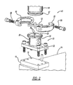
FIG. 2 is an exploded perspective view of a connection. -
FIG. 3 is a plan view of a boom. -
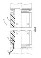
FIG. 4 is a cross-section view ofFIG. 3 . -
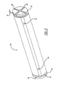
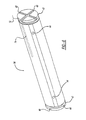
FIG. 5 is a perspective view of the boom. -
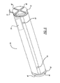
FIG. 6 is a perspective view of the boom of a second embodiment. - Example embodiments will now be described more fully with reference to the accompanying drawings.
-
FIGS. 1 through 5 show one contemplated embodiment of the geometricend effector system 10 according to the present invention. Theend effector system 10 includes aplatform 12 that is preferably made of steel, however it should be noted that any other type of metal, plastic, ceramic, or composite may be used for theplatform 12. Theplatform 12 will have a variety of orifices therethrough to mate with any of the known robotic arms, robotic wrists or the like. Theplatform 12 may be of any known shape, such as a plate with the orifices therethrough, a circular, square, triangular, or any other shaped plate or any other type of platform known to connect to the end of a robot. Theplatform 12 is attached by any known fastening technique, i.e., chemical, mechanical or the like to aframe 14 which is preferably made of a steel material. However, it should be noted that theframe 14 may be made of any other known material such as any other known metal, plastic, ceramic, composite, natural material or the like. Theframe 14 may have any known shape. The shape will depend on the environment in which the robotic cell will be used. Theframe 14 will allow for a plurality of components to be connected thereto such that one robot arm may perform several functions or hold complex geometric parts for operations thereon or movement between stations in a manufacturing environment. - Each
frame 14 will have a plurality ofbase members 16 secured thereto. Thebase members 16 are secured to theframe 14 by any known mechanical or chemical bonding technique such as welding, fastening or the like. Each of thebase members 16 will have a plurality oforifices 18 arranged at predetermined positions thereon. In the embodiment shown theorifices 18 are arranged along near or at each end thereof. Some of theorifices 18 may be threaded while some of the orifices may not be threaded. However, in some embodiments allorifices 18 may be threaded and in some other embodiments none of theorifices 18 are threaded. Thebase 16 generally has a rectangular shape with a predetermined thickness. In the embodiment shown threeorifices 18 are arranged at or near each end of thebase 16. It should be noted that any known shape can be used for thebase members 16 depending on the design requirements and space available for thebase members 16 on theframe 14. Thebase members 16 are generally made of a steel material, however it should be noted that any other metal, plastic, ceramic, composite or the like may be used for thebase members 16 depending on the robotic cell and the environment such robot will be used in. - Secured to the
base member 16 is ananchor mount 20. It should be noted that theanchor mount 20 may be secured to allbase members 16 on a robot endeffector system frame 14 or on just selectedbase members 16 depending on the components to be connected to theframe 14 of the robotend effector system 10. The anchor mount 20 generally has a base 22 that mimics the shape of thebase member 16. Theanchor mount base 22 in the present embodiment generally has a rectangular shape with a predetermined thickness. A plurality oforifices 24 are arranged through the thickness of theanchor mount base 22 to align with and mate with theorifices 18 in theframe base member 16. - Extending from generally a midpoint of the
anchor mount base 22 on one side thereof is a cylindrically shapedmember 26 extending therefrom. Thecylindrical member 26 is fastened to the face of theanchor mount base 22 via any known fastening technique, such as welding or the like, or it is also contemplated to havecylindrical member 26 cast with the base 22 as one member, or made as an extrusion or machined. Arranged at an end of thecylindrical member 26 is acircumferential coupling flange 28. Theflange 28 has a predetermined diameter with a predetermined sized bore or orifice through a midpoint thereof. A plurality ofslots 30 are arranged on the end face of thecoupling flange 28. Theslots 30 extend a predetermined distance into the face of theflange 28. Theslots 30 are arranged on the face such that any number of degrees are located between theslots 30. In the embodiment shown fourslots 30 are positioned within the face of theflange 28. Theslots 30 are arranged at 90° intervals around the ring like face of theflange 28. - The anchor mount 20 is designed such that a
breakaway point 32 occurs generally to where theflange 28 andcylindrical member 26 intersect. Thisintersectional point 32 between theflange 28 andcylindrical member 26 may be designed by either increasing or decreasing the thickness of the material used at thebreakaway point 32 for theanchor mount 20. The reduction of material will create abreakaway point 32 that will fail at a lower force than that of abreakaway point 32 that has a thicker material cross section therethrough. Other methods of creating abreakaway point 32 are also contemplated such as scoring the intersection between theflange 28 andcylindrical member 26, pre-stressing, placing a plurality of notches there along, arranging a plurality of orifices therearound, using a different material, or any other contemplated and known method of creating abreakaway point 32 that will fail at a particular lower force in comparison to other components connected to theanchor mount 20 and within theend effector system 10. Thebreakaway point 32 will create a specific point at which a predetermined force will break theanchor mount 20 in relation to all other components connected to theanchor mount 20 between the robot and the components being held by theend effector system 10. - A
boom 36 and/orjunction member 38 may be secured to theanchor mount 20 via acollar assembly 40. Theboom 36 which generally has a cylindrical shape with a bore through an entire longitudinal length thereof. Theboom 36 will include a generallycircular coupling flange 42 on both ends thereof. Theboom 36 can be of any length or incremental length needed within theend effector system 10. Theboom 36 will also include a plurality oforifices 44 prearranged at predetermined positions such that accessories may be mounted to theboom 36 or thebooms 36 may be connected to components connected thereto or to ananchor mount 20 via a safety harness or the like. Theorifices 44 are predetermined size and arranged at predetermined intervals along theboom 36 depending on the design requirements and the components being held. Thecoupling flange 42 located at each end of theboom 36 have a plurality ofslots 46 therein to align with theslots 30 on theanchor mount 20,other junction members 38 or any other components. Theslots 46 will have the same positioning around the end of theflange 42 and will have the same predetermined depth as that of theanchor mount flange 28. Theboom 36 may have a predetermined thickness thus creating a part that will be able to absorb forces greater than that at thebreakaway point 32 of theanchor mount 20. - The
junction members 38 generally will have at least onecircumferential coupling flange 42 thereon but may have any number ofcoupling flanges 42 and faces thereon such as two face junction members, three face, four face, five face, or the like. Thesejunction members 38 may allow for a connection to theanchor mount 20 at various angles, or with other various components connected thereto. Each of the faces of thejunction members 38 will include a generallycircumferential coupling flange 42 havingslots 46 that are arranged in the same manner as those discussed for theanchor mount flange 28. Otheredge accessory members 48 may also be connected to or used as an end member which connects to a clamp or other component being held by theend effector system 10. Generally, theedge accessory members 48 will have onecircumferential coupling flange 42 arranged thereon but more than one may also be used. Theflange 42 will include thesame slots 46 arranged at the same intervals as those for theanchor mount flange 28. Theedge accessory components 48 will be capable of holding parts at predetermined angles and/or straight as shown inFIG. 1 . - The
boom 36,junction members 38,edge accessory members 48, other components and anchor mounts 20 are all interconnected with each other and fastened to one another in a multitude of combinations. The connections are created via acollar assembly 40. Thecollar assembly 40 includes a first andsecond collar member 50 and across key 52. The cross key 52 generally has an X-shape with a predetermined thickness. The predetermined thickness will be such that approximately half of the cross key 52 will extend into aslot coupling flanges adjacent coupling flange slots collar assembly 40. - The
body 60 of theboom 36 is manufactured from a carbon fiber material 62. Additionally, any type of fiber reinforced material may be utilized. Afeedback sensing element 70 is molded into the fiber reinforced material 62. Thesensing element 70 may be an electric strain gauge,fiber optic cable 74 or the like. Thesensing feedback device 70 provides accurate real time information of what is occurring at thejig 76,fixture 78, or endeffector 80. Thissensing feedback device 70 provides stress and strain of theboom 36 that indicates the deflection and force on the jig, fixture or end effector. This real time determination helps to improve the control of thesystem 10. Thus, the fiber reinforcedboom 36 enables the jigs, fixtures or end effectors to become add-on systems that determine the process and whether or not the operation are functioning satisfactory or if they are out of control. A plurality ofwires 72 are connected with thesensing feedback device 70. Thewires 72 are coupled with the controller (not shown). - The foregoing description of the embodiments has been provided for purposes of illustration and description. It is not intended to be exhaustive or to limit the disclosure. Individual elements or features of a particular embodiment are generally not limited to that particular embodiment, but, where applicable, are interchangeable and can be used in a selected embodiment, even if not specifically shown or described. The same may also be varied in many ways. Such variations are not to be regarded as a departure from the disclosure, and all such modifications are intended to be included within the scope of the disclosure.
Claims (4)
- A boom for an end effector comprising:a cylindrical body including a flange at each end, the body formed from a carbon fiber material; andan electronic feedback mechanism embedded in the carbon fiber material.
- The boom of Claim 1, wherein the electronic feedback mechanism is a strain gauge.
- The boom of Claim 1, wherein the electronic feedback mechanism is a fiber optic cable.
- An effector system comprising:a platform;a frame secured to the platform;a plurality of bases arranged on the frame;an anchor mount secured to at least one of the bases; anda component connected to the anchor mount, the component including a boom according to one of the preceding Claims.
Applications Claiming Priority (2)
| Application Number | Priority Date | Filing Date | Title |
|---|---|---|---|
| US201361840135P | 2013-06-27 | 2013-06-27 | |
| US14/299,297 US9884426B2 (en) | 2013-06-27 | 2014-06-09 | Boom utilized in a geometric end effector system |
Publications (1)
| Publication Number | Publication Date |
|---|---|
| EP2818285A1 true EP2818285A1 (en) | 2014-12-31 |
Family
ID=51210983
Family Applications (1)
| Application Number | Title | Priority Date | Filing Date |
|---|---|---|---|
| EP14174630.5A Withdrawn EP2818285A1 (en) | 2013-06-27 | 2014-06-27 | Boom utilized in a geometric end effector system |
Country Status (4)
| Country | Link |
|---|---|
| US (1) | US9884426B2 (en) |
| EP (1) | EP2818285A1 (en) |
| CA (1) | CA2855036C (en) |
| MX (1) | MX2014007763A (en) |
Citations (6)
| Publication number | Priority date | Publication date | Assignee | Title |
|---|---|---|---|---|
| DE10063030C1 (en) * | 2000-12-18 | 2002-09-05 | Fraunhofer Ges Forschung | Arm for medical robot has composite arm with optical fibre leading to viewing port in arm |
| JP2009160685A (en) * | 2008-01-04 | 2009-07-23 | Nippon Oil Corp | CFRP conveyance member and robot hand using the same |
| US20090248038A1 (en) * | 2008-03-31 | 2009-10-01 | Intuitive Surgical Inc., A Delaware Corporation | Force and torque sensing in a surgical robot setup arm |
| US7609020B2 (en) | 2006-07-11 | 2009-10-27 | Delaware Capital Formation, Inc. | Geometric end effector system |
| EP2116339A1 (en) * | 2008-04-10 | 2009-11-11 | Murata Machinery, Ltd. | Parallel mechanism |
| DE202009008994U1 (en) * | 2009-06-29 | 2010-11-18 | Kuka Systems Gmbh | scaffold construction |
Family Cites Families (18)
| Publication number | Priority date | Publication date | Assignee | Title |
|---|---|---|---|---|
| US4503416A (en) | 1982-12-13 | 1985-03-05 | General Electric Company | Graphite fiber tactile sensor |
| DE19814630B4 (en) | 1998-03-26 | 2011-09-29 | Carl Zeiss | Method and apparatus for manually controlled guiding a tool in a predetermined range of motion |
| EP1168463A1 (en) | 2000-06-23 | 2002-01-02 | DORNIER GmbH | Fiber composite with integrated piezoelectric actor or sensor |
| US6815037B2 (en) | 2001-09-19 | 2004-11-09 | Nippon Mitsubishi Oil Corporation | Carrier member made of a UV resistant fiber-reinforced composite material and process for producing thereof |
| KR100989012B1 (en) | 2002-07-29 | 2010-10-20 | 신닛뽄 세끼유 가부시끼가이샤 | Carbon fiber composite transfer member with reflective surface |
| DE10304019A1 (en) | 2003-02-01 | 2004-11-04 | Kuka Roboter Gmbh | Method for monitoring a machine and such a machine, in particular a robot |
| US8496647B2 (en) | 2007-12-18 | 2013-07-30 | Intuitive Surgical Operations, Inc. | Ribbed force sensor |
| JP2007007762A (en) | 2005-06-29 | 2007-01-18 | Honda Motor Co Ltd | Joint monitoring device for articulated robots |
| ATE449672T1 (en) | 2005-09-16 | 2009-12-15 | Abb Ab | INDUSTRIAL ROBOT WITH SENSOR MEANS IN THE AREA OF A TOOL FLANGE |
| EP1927440A1 (en) | 2006-11-30 | 2008-06-04 | Abb Research Ltd. | Method and device for monitoring the condition of an industrial robot |
| EP1932629B1 (en) | 2006-12-11 | 2019-04-24 | ABB Research Ltd. | A method and a control system for monitoring the condition of an industrial robot |
| EP1955830B1 (en) | 2007-02-06 | 2014-04-09 | Abb Research Ltd. | A method and a control system for monitoring the condition of an industrial robot |
| US20080247857A1 (en) | 2007-04-05 | 2008-10-09 | Ichiro Yuasa | End effector and robot for transporting substrate |
| WO2009034477A2 (en) * | 2007-04-16 | 2009-03-19 | The Governors Of The University Of Calgary | Frame mapping and force feedback methods, devices and systems |
| US8965485B2 (en) * | 2007-11-01 | 2015-02-24 | University Of Utah Research Foundation | Integrated surgical cutting system |
| DE102007063099A1 (en) | 2007-12-28 | 2009-07-02 | Kuka Roboter Gmbh | Robot and method for monitoring the moments on such |
| JP5353500B2 (en) | 2009-07-08 | 2013-11-27 | 株式会社安川電機 | robot |
| US8679125B2 (en) * | 2010-09-22 | 2014-03-25 | Biomet Manufacturing, Llc | Robotic guided femoral head reshaping |
-
2014
- 2014-06-09 US US14/299,297 patent/US9884426B2/en active Active
- 2014-06-24 MX MX2014007763A patent/MX2014007763A/en not_active Application Discontinuation
- 2014-06-25 CA CA2855036A patent/CA2855036C/en active Active
- 2014-06-27 EP EP14174630.5A patent/EP2818285A1/en not_active Withdrawn
Patent Citations (7)
| Publication number | Priority date | Publication date | Assignee | Title |
|---|---|---|---|---|
| DE10063030C1 (en) * | 2000-12-18 | 2002-09-05 | Fraunhofer Ges Forschung | Arm for medical robot has composite arm with optical fibre leading to viewing port in arm |
| US7609020B2 (en) | 2006-07-11 | 2009-10-27 | Delaware Capital Formation, Inc. | Geometric end effector system |
| US7940023B2 (en) | 2006-07-11 | 2011-05-10 | Delaware Capital Formation, Inc. | Geometric end effector system |
| JP2009160685A (en) * | 2008-01-04 | 2009-07-23 | Nippon Oil Corp | CFRP conveyance member and robot hand using the same |
| US20090248038A1 (en) * | 2008-03-31 | 2009-10-01 | Intuitive Surgical Inc., A Delaware Corporation | Force and torque sensing in a surgical robot setup arm |
| EP2116339A1 (en) * | 2008-04-10 | 2009-11-11 | Murata Machinery, Ltd. | Parallel mechanism |
| DE202009008994U1 (en) * | 2009-06-29 | 2010-11-18 | Kuka Systems Gmbh | scaffold construction |
Non-Patent Citations (1)
| Title |
|---|
| "EOAT Interactive Tooling Catalog v1.5", 25 April 2013 (2013-04-25), XP055148957, Retrieved from the Internet <URL:http://www.norgren.com/automationsolutions/downloads/download/23/robot_end_of_arm_tooling_eoat_interactive_catalog> [retrieved on 20141027] * |
Also Published As
| Publication number | Publication date |
|---|---|
| MX2014007763A (en) | 2015-06-22 |
| US9884426B2 (en) | 2018-02-06 |
| CA2855036A1 (en) | 2014-12-27 |
| US20150003947A1 (en) | 2015-01-01 |
| CA2855036C (en) | 2021-08-10 |
Similar Documents
| Publication | Publication Date | Title |
|---|---|---|
| US7609020B2 (en) | Geometric end effector system | |
| JP6527552B2 (en) | Automatic assembly of panel type aircraft fuselage | |
| JP5733968B2 (en) | Method and apparatus for automatic positioning and alignment for aircraft structures using robots | |
| US10173327B2 (en) | Device for use in the handling of a load and method for producing such a device | |
| EP2965876A2 (en) | Clamping feet for an end effector | |
| DE112009004288T5 (en) | Set of multi-axis force and torque sensors and assembly methods | |
| US9032687B2 (en) | System for manufacturing a reinforcement | |
| EP2500149A2 (en) | Robot system | |
| US10035269B2 (en) | Enhanced robotic teaching tool | |
| JP6563271B2 (en) | Assembly manufacturing apparatus and assembly manufacturing method | |
| JP2020059115A (en) | Attaching mechanism, robot apparatus, and attaching method | |
| DE202011000150U1 (en) | change coupling | |
| US20160067868A1 (en) | Modular end effector | |
| DE102014210362A1 (en) | MRK workstation with a jig | |
| JP2022533114A (en) | Adapter replacement system for robotization system | |
| US9884426B2 (en) | Boom utilized in a geometric end effector system | |
| EP3441200A1 (en) | Referencing method and device for industrial robots | |
| US20180236658A1 (en) | Assembly System and Method For Inserting a Terminal Into a Housing | |
| CN107053255B (en) | Clamp assembly for servicing heavy equipment | |
| CA2895735C (en) | Clamping feet for an end effector | |
| DE102016110877A1 (en) | Method for attaching a mobile machine tool and mobile machine tool | |
| EP4015163B1 (en) | Gripping tool | |
| CN221047628U (en) | Error-proofing mechanism for different sleeves | |
| US7246965B2 (en) | Method of assembling a link to a support, and a vibration-damping device manufactured by said method | |
| KR20250012984A (en) | Fixture device for work piece |
Legal Events
| Date | Code | Title | Description |
|---|---|---|---|
| PUAI | Public reference made under article 153(3) epc to a published international application that has entered the european phase |
Free format text: ORIGINAL CODE: 0009012 |
|
| 17P | Request for examination filed |
Effective date: 20140627 |
|
| AK | Designated contracting states |
Kind code of ref document: A1 Designated state(s): AL AT BE BG CH CY CZ DE DK EE ES FI FR GB GR HR HU IE IS IT LI LT LU LV MC MK MT NL NO PL PT RO RS SE SI SK SM TR |
|
| AX | Request for extension of the european patent |
Extension state: BA ME |
|
| RAP1 | Party data changed (applicant data changed or rights of an application transferred) |
Owner name: DE-STA-CO EUROPE GMBH |
|
| STAA | Information on the status of an ep patent application or granted ep patent |
Free format text: STATUS: THE APPLICATION IS DEEMED TO BE WITHDRAWN |
|
| 18D | Application deemed to be withdrawn |
Effective date: 20150701 |