EP2818249B1 - Support assembly for supporting part of a machine and processing apparatus provided with this support assembly - Google Patents
Support assembly for supporting part of a machine and processing apparatus provided with this support assembly Download PDFInfo
- Publication number
- EP2818249B1 EP2818249B1 EP13191478.0A EP13191478A EP2818249B1 EP 2818249 B1 EP2818249 B1 EP 2818249B1 EP 13191478 A EP13191478 A EP 13191478A EP 2818249 B1 EP2818249 B1 EP 2818249B1
- Authority
- EP
- European Patent Office
- Prior art keywords
- machine
- mounting member
- feed conveyor
- respect
- retracted
- Prior art date
- Legal status (The legal status is an assumption and is not a legal conclusion. Google has not performed a legal analysis and makes no representation as to the accuracy of the status listed.)
- Active
Links
Images




Classifications
-
- B—PERFORMING OPERATIONS; TRANSPORTING
- B65—CONVEYING; PACKING; STORING; HANDLING THIN OR FILAMENTARY MATERIAL
- B65G—TRANSPORT OR STORAGE DEVICES, e.g. CONVEYORS FOR LOADING OR TIPPING, SHOP CONVEYOR SYSTEMS OR PNEUMATIC TUBE CONVEYORS
- B65G41/00—Supporting frames or bases for conveyors as a whole, e.g. transportable conveyor frames
- B65G41/001—Supporting frames or bases for conveyors as a whole, e.g. transportable conveyor frames with the conveyor adjustably mounted on the supporting frame or base
-
- B—PERFORMING OPERATIONS; TRANSPORTING
- B65—CONVEYING; PACKING; STORING; HANDLING THIN OR FILAMENTARY MATERIAL
- B65G—TRANSPORT OR STORAGE DEVICES, e.g. CONVEYORS FOR LOADING OR TIPPING, SHOP CONVEYOR SYSTEMS OR PNEUMATIC TUBE CONVEYORS
- B65G21/00—Supporting or protective framework or housings for endless load-carriers or traction elements of belt or chain conveyors
-
- B—PERFORMING OPERATIONS; TRANSPORTING
- B02—CRUSHING, PULVERISING, OR DISINTEGRATING; PREPARATORY TREATMENT OF GRAIN FOR MILLING
- B02C—CRUSHING, PULVERISING, OR DISINTEGRATING IN GENERAL; MILLING GRAIN
- B02C21/00—Disintegrating plant with or without drying of the material
- B02C21/02—Transportable disintegrating plant
- B02C21/026—Transportable disintegrating plant self-propelled
-
- B—PERFORMING OPERATIONS; TRANSPORTING
- B65—CONVEYING; PACKING; STORING; HANDLING THIN OR FILAMENTARY MATERIAL
- B65G—TRANSPORT OR STORAGE DEVICES, e.g. CONVEYORS FOR LOADING OR TIPPING, SHOP CONVEYOR SYSTEMS OR PNEUMATIC TUBE CONVEYORS
- B65G21/00—Supporting or protective framework or housings for endless load-carriers or traction elements of belt or chain conveyors
- B65G21/10—Supporting or protective framework or housings for endless load-carriers or traction elements of belt or chain conveyors movable, or having interchangeable or relatively movable parts; Devices for moving framework or parts thereof
- B65G21/12—Supporting or protective framework or housings for endless load-carriers or traction elements of belt or chain conveyors movable, or having interchangeable or relatively movable parts; Devices for moving framework or parts thereof to allow adjustment of position of load-carrier or traction element as a whole
-
- B—PERFORMING OPERATIONS; TRANSPORTING
- B65—CONVEYING; PACKING; STORING; HANDLING THIN OR FILAMENTARY MATERIAL
- B65G—TRANSPORT OR STORAGE DEVICES, e.g. CONVEYORS FOR LOADING OR TIPPING, SHOP CONVEYOR SYSTEMS OR PNEUMATIC TUBE CONVEYORS
- B65G21/00—Supporting or protective framework or housings for endless load-carriers or traction elements of belt or chain conveyors
- B65G21/10—Supporting or protective framework or housings for endless load-carriers or traction elements of belt or chain conveyors movable, or having interchangeable or relatively movable parts; Devices for moving framework or parts thereof
- B65G21/14—Supporting or protective framework or housings for endless load-carriers or traction elements of belt or chain conveyors movable, or having interchangeable or relatively movable parts; Devices for moving framework or parts thereof to allow adjustment of length or configuration of load-carrier or traction element
-
- B—PERFORMING OPERATIONS; TRANSPORTING
- B65—CONVEYING; PACKING; STORING; HANDLING THIN OR FILAMENTARY MATERIAL
- B65G—TRANSPORT OR STORAGE DEVICES, e.g. CONVEYORS FOR LOADING OR TIPPING, SHOP CONVEYOR SYSTEMS OR PNEUMATIC TUBE CONVEYORS
- B65G41/00—Supporting frames or bases for conveyors as a whole, e.g. transportable conveyor frames
- B65G41/001—Supporting frames or bases for conveyors as a whole, e.g. transportable conveyor frames with the conveyor adjustably mounted on the supporting frame or base
- B65G41/002—Pivotably mounted
-
- B—PERFORMING OPERATIONS; TRANSPORTING
- B65—CONVEYING; PACKING; STORING; HANDLING THIN OR FILAMENTARY MATERIAL
- B65G—TRANSPORT OR STORAGE DEVICES, e.g. CONVEYORS FOR LOADING OR TIPPING, SHOP CONVEYOR SYSTEMS OR PNEUMATIC TUBE CONVEYORS
- B65G41/00—Supporting frames or bases for conveyors as a whole, e.g. transportable conveyor frames
- B65G41/001—Supporting frames or bases for conveyors as a whole, e.g. transportable conveyor frames with the conveyor adjustably mounted on the supporting frame or base
- B65G41/005—Supporting frames or bases for conveyors as a whole, e.g. transportable conveyor frames with the conveyor adjustably mounted on the supporting frame or base mounted for both pivotal and linear movement
-
- B—PERFORMING OPERATIONS; TRANSPORTING
- B65—CONVEYING; PACKING; STORING; HANDLING THIN OR FILAMENTARY MATERIAL
- B65G—TRANSPORT OR STORAGE DEVICES, e.g. CONVEYORS FOR LOADING OR TIPPING, SHOP CONVEYOR SYSTEMS OR PNEUMATIC TUBE CONVEYORS
- B65G41/00—Supporting frames or bases for conveyors as a whole, e.g. transportable conveyor frames
- B65G41/007—Means for moving conveyor frames and control arrangements therefor
- B65G41/008—Means for moving conveyor frames and control arrangements therefor frames mounted on wheels or caterpillar
-
- Y—GENERAL TAGGING OF NEW TECHNOLOGICAL DEVELOPMENTS; GENERAL TAGGING OF CROSS-SECTIONAL TECHNOLOGIES SPANNING OVER SEVERAL SECTIONS OF THE IPC; TECHNICAL SUBJECTS COVERED BY FORMER USPC CROSS-REFERENCE ART COLLECTIONS [XRACs] AND DIGESTS
- Y10—TECHNICAL SUBJECTS COVERED BY FORMER USPC
- Y10T—TECHNICAL SUBJECTS COVERED BY FORMER US CLASSIFICATION
- Y10T403/00—Joints and connections
- Y10T403/32—Articulated members
Definitions
- the present invention relates to a support assembly for a feed conveyor of a material processing apparatus and particularly, but not exclusively, to a support assembly for a feed conveyor of an aggregate processing machine.
- Such machines typically comprise a chassis having one or more material processing devices mounted thereon for screening, separating, crushing and/or washing one or more types of aggregate material, for example rocks, stones, gravel, sand and/or soil, or any other material that is quarried, mined or excavated.
- material processing devices mounted thereon for screening, separating, crushing and/or washing one or more types of aggregate material, for example rocks, stones, gravel, sand and/or soil, or any other material that is quarried, mined or excavated.
- the processing machine is mobile and comprises one or more wheels and/or tracks mounted on the chassis.
- the machine is usually self-propelled incorporating a drive unit, such as an engine, for driving the wheels and/or tracks.
- a feed hopper for receiving material to be processed, the hopper being mounted above a loading end of a feed conveyor, the feed conveyor having a discharge end for delivering the material to the one or more material processing devices.
- the discharge end of the feed conveyor is required to be located at a higher level so that the material can be fed under the action of gravity to said one or more processing devices, such as a crushing device or screening device. Therefore the feed conveyor is typically upwardly inclined. However, if the angle of inclination of the feed conveyor is too steep, the feed conveyor may be unable to deliver heavier material to the one or more processing devices as the material may simply roll down the conveyor. Therefore it is desirable to permit adjustment of the angle of inclination of the feed conveyor to suit the material being processed.
- United States Patent US3552546 discloses a portable belt conveyor with a telescopic support having a first member, a second member and a mounting member which can adjust the angle of the conveyor. It would be desirable to improve on the conveyor of US3552546 .
- the invention provides a material processing machine as claimed in claim 1.
- Preferred embodiments include a support assembly for supporting a part of a machine, the support assembly comprising at least one support member for supporting a part of the machine on a base, the support member being slid ably mounted on a mounting member on the base to be displaceable with respect to the mounting member between a retracted position and an extended position, a jacking leg extending from a lower end of the mounting member to be displaceable between a retracted position and an extended position, a ram acting between the jacking leg and the support member, said ram being operable to move the jacking leg between its retracted and extended positions and to move the support member between its retracted and extended positions to adjust the position of said part of the machine relative to the base.
- Preferred embodiments include a feed conveyor, wherein a loading end of the feed conveyor is support on a support assembly in accordance with the second aspect of the invention.
- Preferred embodiments include a chassis having at least one material processing device mounted thereon and a feed conveyor for feeding material to said at least one material processing device, said feed conveyor having a loading end and a discharge end, the loading end of the feed conveyor being supported on the chassis via a support assembly adapted to enable adjustment the height of the loading end of the feed conveyor with respect to the chassis, and thus adjustment of the angle of inclination of the feed conveyor.
- the apparatus may be embodied as a mobile aggregate processing apparatus comprising in operative combination:
- an aggregate or other material processing machine is configured for performing, by way of example, aggregate or other material screening and, as such, in the example shown comprises a screening plant in particular an aggregate screening plant 12.
- the machine 10 may be configured to perform any one or more of a plurality of processes, such as feeding, screening, separating, crushing and/or washing, on one or more types of aggregate material, for example rocks, stones, gravel, sand and/or soil, or any other material that is quarried, mined or excavated.
- the machine 10 may include one or more material processing plants adapted to perform one or more of the foregoing processes.
- the processing machine 10 is mobile and comprises one or more wheels and/or tracks 11 mounted on a chassis 13.
- the machine 10 may be self-propelled and to this end may comprise a drive system, e.g. comprising an engine, for driving the wheels or tracks 11 as applicable.
- a drive system e.g. comprising an engine
- the machine 10 is usually provided with wheels for this purpose.
- the processing machine 10 comprises a feed conveyor 14 for feeding material to the material processing plant 12, the feed conveyor 14 having loading end, preferably at a rear end of the chassis 13, and a discharge end for feeding material to said material processing plant 12, the feed conveyor 14 being mounted on the chassis 13 such that the conveying surface thereof is inclined upwardly from the loading end to the discharge end of the feed conveyor 14.
- a feed hopper 15 is mounted above the loading end of the feed conveyor 14 for receiving material to be processed.
- the feed conveyor 14 is mounted on the chassis 13 of the machine 10 such that the height of the loading end of the feed conveyor 14, and thus the angle of inclination of the feed conveyor 14, can be adjusted, as will be described in more detail below.
- a pair of jacking legs 16,18 are mounted on either side of the chassis 13 at a rear end thereof, adjacent the feed hopper 15 of the feed conveyor 14.
- the jacking legs 16,18 are mounted on the chassis 13 to be vertically extendable between a retracted or raised position, allowing the machine 10 to be moved over the ground, and an extended or lowered position (shown in Figure 1 ), wherein the jacking legs 16,18 engage the ground to support the rear end of the machine 10.
- the discharge end of the feed conveyor 14 is pivotally mounted on the chassis 13 to allow the feed conveyor 14 to be tilted about a horizontal axis 20 extending transverse to a longitudinal axis of the chassis 13 to enable the angle of inclination of the feed conveyor 14 to be adjusted.
- the loading end of the feed conveyor 14 is supported on a support beam 22, extending transverse to the longitudinal axis of the chassis 13.
- support rollers 23A,23B are mounted on an upper side of the support beam 22, adjacent each end thereof, for supporting a lower side of the feed conveyor 14 thereon.
- the support beam 22 is integrally mounted on the chassis 13 with the jacking legs 16,18, providing a particularly compact and efficient arrangement, as will be described below in more detail.
- each mounting post 24,26 comprising an elongate square section tubular body having a respective flange 25,27 welded on one side thereof at a lower end thereof by means of which the mounting post 24,26 is bolted to a respective side of the chassis 13 such that the tubular body of each mounting post 24,26 extends upwardly from the chassis 13.
- a respective jacking leg 16,18 is slidably located within each mounting post 24,26 to be vertically slideable within the respective mounting post 24,26 between retracted and extended positions, the tubular body of the mounting post 24,26 defining a housing for the jacking leg 16,18 when it is in its retracted position.
- Each jacking leg 16,18 comprises a square section tube having a foot 28A,28B provided at a lower end thereof, said tube being dimensioned to fit within the tubular body of the respective mounting post 24,26.
- the support beam 22 is mounted on the chassis by a pair of elongate vertically arranged tubular support members 30,32 provided at either end of the support beam 22, each support member 30,32 being located over a respective mounting post 24,26 to be slidably received thereon.
- a hydraulic ram 34,36 is mounted within each mounting post 24,26 to act between the respective jacking leg 16,18 and the support member 30,32 of the support beam 22 associated therewith, such that each ram 34,36 can be extended to extend the jacking legs 16,18 to their extended positions and to selectively raise the support members 30,32 of the supper beam with respect to the mounting posts 24,26 to raise the height of the support beam 22, and thus the height of the loading end of the feed conveyor 14.
- a respective tab 38 extends from a side of each mounting post 24,26 to be received with an elongate slot 39 formed in a side of the respective support member 30,32 of the support beam 22, a pair of flanges 40,41 being provided on either side of the slot 39 of each support member 30,32.
- a pin receiving aperture is provided in each tab 38 and aligned pairs of apertures 44,45,46 are provided at vertically spaced locations in the flanges 40,41 on either side of each slot 39, so that the vertical position of the support beam 22 can be fixed in an uppermost or fully raised position, a lowermost or fully lowered position and one or more intermediate positions by inserting an upper locking pin 43 through selected aligned apertures 44,45,46 in the flanges 40,41 and through the pin receiving aperture in the tab 38 of the respective mounting post 24,26.
- locking pins 42 may be provided to be insertable through respectively aligned apertures in the mounting posts 24,26 and the jacking legs 16,18 for locking the jacking legs 16,18 in their retracted or extended positions.
- the lower locking pins 42 are removed and the rams 34,36 are extended to extend the jacking legs 16,18 from their retracted position to their ground engaging extended position.
- the height of the support beam 22 is fixed by means of the locking pins 43 inserted through the appropriate apertures in the flanges 40,41 of the support members 30,32 of the support beam 22 and respective tabs 38 of the mounting posts 24,26, locking the support members 30,32 in position on the support posts 24,26.
- the lower locking pins 42 are subsequently reinserted to lock the jacking legs 16,18 in position.
- the upper locking pins 43 are removed and the rams 34,36 are extended or retracted to raise or lower the support members 30,32,and thus the support beam 22, with respect to the mounting posts 24,26.
- the upper locking pins 43 are inserted through the apertures in the flanges 40,41 of each slot and the aperture in the tab 38 of the mounting post 24,26 aligned therewith to lock the support beam 22 in position with respect to the chassis 13.
Landscapes
- Engineering & Computer Science (AREA)
- Mechanical Engineering (AREA)
- Food Science & Technology (AREA)
- Disintegrating Or Milling (AREA)
Description
- The present invention relates to a support assembly for a feed conveyor of a material processing apparatus and particularly, but not exclusively, to a support assembly for a feed conveyor of an aggregate processing machine.
- It is known to provide mobile self-propelled crushing and screening machines for processing materials, such as aggregates, in a quarry or for recycling demolition waste.
- Such machines typically comprise a chassis having one or more material processing devices mounted thereon for screening, separating, crushing and/or washing one or more types of aggregate material, for example rocks, stones, gravel, sand and/or soil, or any other material that is quarried, mined or excavated.
- Typically, the processing machine is mobile and comprises one or more wheels and/or tracks mounted on the chassis. The machine is usually self-propelled incorporating a drive unit, such as an engine, for driving the wheels and/or tracks.
- Typically a feed hopper is provided for receiving material to be processed, the hopper being mounted above a loading end of a feed conveyor, the feed conveyor having a discharge end for delivering the material to the one or more material processing devices.
- It is desirable to locate the feed hopper at a relatively low level to reduce the need to raise material to be loaded into the feed hopper onto the feed conveyor. The discharge end of the feed conveyor is required to be located at a higher level so that the material can be fed under the action of gravity to said one or more processing devices, such as a crushing device or screening device. Therefore the feed conveyor is typically upwardly inclined. However, if the angle of inclination of the feed conveyor is too steep, the feed conveyor may be unable to deliver heavier material to the one or more processing devices as the material may simply roll down the conveyor. Therefore it is desirable to permit adjustment of the angle of inclination of the feed conveyor to suit the material being processed.
-
- The invention provides a material processing machine as claimed in claim 1.
- Preferred embodiments include a support assembly for supporting a part of a machine, the support assembly comprising at least one support member for supporting a part of the machine on a base, the support member being slid ably mounted on a mounting member on the base to be displaceable with respect to the mounting member between a retracted position and an extended position, a jacking leg extending from a lower end of the mounting member to be displaceable between a retracted position and an extended position, a ram acting between the jacking leg and the support member, said ram being operable to move the jacking leg between its retracted and extended positions and to move the support member between its retracted and extended positions to adjust the position of said part of the machine relative to the base.
- Preferred embodiments include a feed conveyor, wherein a loading end of the feed conveyor is support on a support assembly in accordance with the second aspect of the invention.
- Preferred embodiments include a chassis having at least one material processing device mounted thereon and a feed conveyor for feeding material to said at least one material processing device, said feed conveyor having a loading end and a discharge end, the loading end of the feed conveyor being supported on the chassis via a support assembly adapted to enable adjustment the height of the loading end of the feed conveyor with respect to the chassis, and thus adjustment of the angle of inclination of the feed conveyor.
- The apparatus may be embodied as a mobile aggregate processing apparatus comprising in operative combination:
- a frame having a longitudinal direction:
- at least one material processing plant configured to perform at least one of feeding material, washing material, sorting material into first predetermined material dimension groups and crushing material with a first larger dimension characteristic into material having a first smaller dimension characteristic;
- a feed conveyor having a loading end and a discharge end, material from said discharge end being delivered to said material processing plant, wherein the loading end of the feed conveyor is supported on an elongate support beam extending transverse to the longitudinal direction of the frame;
- a tubular support member being provided at each end of the support beam, each support member being mounted on a respective mounting member provided on each side of the frame to be displaceable with respect to the respective mounting member between a lowered position and a raised position;
- an elongate jacking leg being mounted on each mounting member to be displaceable with respect to the respective mounting member extendable between a retracted position to an extended ground engaging position;
- a ram being associated with each jacking leg, each ram acting between the respective jacking leg and the associated support member such that extension of the rams may extend the jacking legs towards their extended ground engaging position and may extend the support members from their lowered position to their raised position to raise the support beam and thus raise the loading end of the feed conveyor.
- Preferred features of the invention are recited in the dependent claims.
- Further advantageous aspects of the invention will become apparent to those ordinarily skilled in the art upon review of the following description of a preferred embodiment and with reference to the accompanying drawings.
- An embodiment of the invention is now described by way of example and with reference to the accompanying drawings in which:
-
Figure 1 is a side view of a mobile aggregate processing machine including a feed conveyor support assembly embodying the invention; -
Figure 2 is a perspective partial view of the support assembly ofFigure 1 ; -
Figure 3 is a sectional perspective view of the support assembly ofFigure 1 ; -
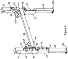
Figure 4 is a perspective partial view of the support assembly ofFigure 1 , showing the jacking legs in their extended position; -
Figure 5 is a perspective partial view of the support structure ofFigures 1 , showing the jacking legs in their extended position and the feed conveyor support beam in its fully raised position; and -
Figure 6 is a sectional perspective view of the support structure ofFigure 1 showing the jacking legs in their extended position and the feed conveyor support beam in its fully raised position. - Referring now to
Figure 1 of the drawings, there is shown, generally indicated as 10, an aggregate or other material processing machine. Theprocessing machine 10 is configured for performing, by way of example, aggregate or other material screening and, as such, in the example shown comprises a screening plant in particular anaggregate screening plant 12. - Alternatively, however, the
machine 10 may be configured to perform any one or more of a plurality of processes, such as feeding, screening, separating, crushing and/or washing, on one or more types of aggregate material, for example rocks, stones, gravel, sand and/or soil, or any other material that is quarried, mined or excavated. To this end, themachine 10 may include one or more material processing plants adapted to perform one or more of the foregoing processes. - Typically, the
processing machine 10 is mobile and comprises one or more wheels and/ortracks 11 mounted on achassis 13. Themachine 10 may be self-propelled and to this end may comprise a drive system, e.g. comprising an engine, for driving the wheels ortracks 11 as applicable. In cases where themachine 10 is towable, it is usually provided with wheels for this purpose. - In the illustrated example, the
processing machine 10 comprises afeed conveyor 14 for feeding material to thematerial processing plant 12, thefeed conveyor 14 having loading end, preferably at a rear end of thechassis 13, and a discharge end for feeding material to saidmaterial processing plant 12, thefeed conveyor 14 being mounted on thechassis 13 such that the conveying surface thereof is inclined upwardly from the loading end to the discharge end of thefeed conveyor 14. Afeed hopper 15 is mounted above the loading end of thefeed conveyor 14 for receiving material to be processed. - The
feed conveyor 14 is mounted on thechassis 13 of themachine 10 such that the height of the loading end of thefeed conveyor 14, and thus the angle of inclination of thefeed conveyor 14, can be adjusted, as will be described in more detail below. In order to provide stability for themachine 10, a pair ofjacking legs chassis 13 at a rear end thereof, adjacent thefeed hopper 15 of thefeed conveyor 14. Thejacking legs chassis 13 to be vertically extendable between a retracted or raised position, allowing themachine 10 to be moved over the ground, and an extended or lowered position (shown inFigure 1 ), wherein thejacking legs machine 10. - The discharge end of the
feed conveyor 14 is pivotally mounted on thechassis 13 to allow thefeed conveyor 14 to be tilted about ahorizontal axis 20 extending transverse to a longitudinal axis of thechassis 13 to enable the angle of inclination of thefeed conveyor 14 to be adjusted. The loading end of thefeed conveyor 14 is supported on asupport beam 22, extending transverse to the longitudinal axis of thechassis 13. As can be seen fromFigure 2 ,support rollers support beam 22, adjacent each end thereof, for supporting a lower side of thefeed conveyor 14 thereon. - The
support beam 22 is integrally mounted on thechassis 13 with thejacking legs - As illustrated in
Figures 2 to 6 , thejacking legs chassis 13 via respective vertically arrangedmounting posts chassis 13 at a rear end thereof, eachmounting post respective flange mounting post chassis 13 such that the tubular body of eachmounting post chassis 13. Arespective jacking leg mounting post respective mounting post mounting post jacking leg - Each
jacking leg foot respective mounting post - The
support beam 22 is mounted on the chassis by a pair of elongate vertically arrangedtubular support members support beam 22, eachsupport member respective mounting post - A
hydraulic ram mounting post respective jacking leg support member support beam 22 associated therewith, such that eachram jacking legs support members mounting posts support beam 22, and thus the height of the loading end of thefeed conveyor 14. - A
respective tab 38 extends from a side of eachmounting post elongate slot 39 formed in a side of therespective support member support beam 22, a pair offlanges slot 39 of eachsupport member - A pin receiving aperture is provided in each
tab 38 and aligned pairs ofapertures flanges slot 39, so that the vertical position of thesupport beam 22 can be fixed in an uppermost or fully raised position, a lowermost or fully lowered position and one or more intermediate positions by inserting anupper locking pin 43 through selectedaligned apertures flanges tab 38 of therespective mounting post - Further (lower)
locking pins 42 may be provided to be insertable through respectively aligned apertures in themounting posts jacking legs jacking legs - In use, when it is desired to extend the
jacking legs machine 10, thelower locking pins 42 are removed and therams jacking legs support beam 22 is fixed by means of thelocking pins 43 inserted through the appropriate apertures in theflanges support members support beam 22 andrespective tabs 38 of themounting posts support members support posts lower locking pins 42 are subsequently reinserted to lock thejacking legs - When it is desired to adjust the vertical position of the loading end of the
feed conveyor 14 with respect to thechassis 13, to adjust the angle of inclination of thefeed conveyor 14, the upper locking pins 43 are removed and therams support members support beam 22, with respect to the mountingposts support beam 22 is at the desired height, the upper locking pins 43 are inserted through the apertures in theflanges tab 38 of the mountingpost support beam 22 in position with respect to thechassis 13.
Claims (13)
- A material processing machine (10) comprising a first part (14), a second part (28A, 28B) and an intermediate part (13), the machine further comprising an apparatus for coupling said first and second parts to said intermediate part, said apparatus comprising a first member (30, 32) connected to said first part (14), said first member being mounted on a mounting member (24, 26) connected to said intermediate part (13) and being movable between an extended position and a retracted position with respect to said mounting member (24,26) to adjust the position of the first part with respect to said intermediate part (13), the apparatus further comprising a second member (16, 18) connected to said second part, said second member (16,18) being mounted on said mounting member (24,26) and being movable between an extended position and a retracted position with respect to said mounting member (24,26) to adjust the position of the second part with respect to said intermediate part, (13), an actuator (34, 36) acting between the first member (30,32) and the second member (16,18), said actuator (34,36) being operable to move the first member (30,32) between its retracted and extended positions and to move the second member (16,18) between its retracted and extended positions.
- A machine as claimed in claim 1, wherein said actuator (34, 36) comprises a linear actuator, said first (30, 32) and second members (16, 18) being arranged for movement between their respective retracted and extended positions along a common axis, said actuator for example comprising a hydraulic ram or pneumatic ram.
- A machine as claimed in claim 1 or claim 2, wherein said first member (30, 32) second member (16, 18) and mounting member (24, 26) are telescopically coupled to one another, and wherein preferably said first, second and mounting members comprise nested tubular members.
- A machine as claimed in any preceding claim, wherein one or more locating means (42, 43) are provided adapted to selectively lock the position of the first and/or second member with respect to the mounting member (24, 26).
- A machine as claimed in any preceding claim, wherein said first member (30, 32) comprises a support member for supporting said first part (14) of the machine, said second member (16, 18) comprises a ground engaging member for supporting or stabilising a body of the machine, and said mounting member (24, 26) is attached to the body (13) of the machine.
- A machine as claimed in claim 1, wherein said apparatus is a support assembly for supporting said first part (14) of the machine, said first member (30, 32) being a support member for supporting said first part of the machine on said intermediate part (13), said intermediate part being a base, the support member being slidably mounted on said mounting member (24, 26) on the base to be displaceable with respect to the mounting member between a retracted position and an extended position, said second member (16, 18) being a jacking leg extending from a lower end of the mounting member to be displaceable between a retracted position and an extended position, said actuator (34, 36) acting between the jacking leg and the support member, said actuator being operable to move the jacking leg between its retracted and extended positions and to move the support member between its retracted and extended positions to adjust the position of said first part of the machine relative to the base.
- A machine as claimed in claim 6, wherein one or more locating means (42, 43) are provided for selectively fixing the position of the support member (30, 32) and/or the jacking leg (16, 18) with respect to the base (13).
- A machine as claimed in claim 7, wherein the or each locating means (42, 43) comprises a respective locking member, such as a locking pin, to be received in aligned receiving apertures (44, 45, 46) provided on cooperating portions (40, 41) of the respective mounting member and support member or jacking leg when the support member or jacking leg is in its retracted and/or extended position and/or one or more intermediate positions with respect to the mounting member.
- A machine as claimed in any one of claims 6 to 8, wherein the support member (30, 32) and jacking leg (16, 18) are arranged to be telescopically extendable with respect to the mounting member (24, 26).
- A machine as claimed in claim 9, wherein the mounting member (24, 26) comprises a tubular body adapted to receive the jacking leg (16, 18) therein in sliding engagement with an inner surface of the tubular body, and wherein, preferably, the support member comprises a tubular body adapted to be received over the mounting member in sliding engagement with an outer surface of the mounting member.
- A machine as claimed in claim 9 or claim 10, wherein the mounting member (24, 26) comprises an elongate tubular post mounted on the base, the jacking leg (16, 18) being received within the mounting member in telescopic manner.
- A machine as claimed in any one of claims 6 to 11, comprising a feed conveyor (14) wherein said first part of the machine comprises a loading end of the feed conveyor.
- A machine as claimed in claim 12, wherein the intermediate part is a chassis (13) having at least one material processing device (12) mounted thereon and said feed conveyor (14) for feeding material to said at least one material processing device, said feed conveyor having said loading end and a discharge end, the loading end of the feed conveyor being supported on the chassis via said support assembly adapted to enable adjustment of the height of the loading end of the feed conveyor with respect to the chassis, and thus adjustment of the angle of inclination of the feed conveyor .
Applications Claiming Priority (1)
| Application Number | Priority Date | Filing Date | Title |
|---|---|---|---|
| GB1220156.2A GB2507767A (en) | 2012-11-08 | 2012-11-08 | Conveyor adjustable input support frame |
Publications (2)
| Publication Number | Publication Date |
|---|---|
| EP2818249A1 EP2818249A1 (en) | 2014-12-31 |
| EP2818249B1 true EP2818249B1 (en) | 2017-01-04 |
Family
ID=47470314
Family Applications (1)
| Application Number | Title | Priority Date | Filing Date |
|---|---|---|---|
| EP13191478.0A Active EP2818249B1 (en) | 2012-11-08 | 2013-11-04 | Support assembly for supporting part of a machine and processing apparatus provided with this support assembly |
Country Status (4)
| Country | Link |
|---|---|
| US (1) | US9260249B2 (en) |
| EP (1) | EP2818249B1 (en) |
| AU (1) | AU2013254926B2 (en) |
| GB (1) | GB2507767A (en) |
Families Citing this family (6)
| Publication number | Priority date | Publication date | Assignee | Title |
|---|---|---|---|---|
| US9643800B2 (en) * | 2013-02-23 | 2017-05-09 | Phillip Douglas | Horizontal support system |
| EP3046404B1 (en) * | 2013-09-09 | 2018-01-10 | Fuji Machine Mfg. Co., Ltd. | Manufacturing work machine |
| CN103968212A (en) * | 2014-05-16 | 2014-08-06 | 苏州新协力特种工业模板有限公司 | Mechanical device installing frame |
| CN106005893A (en) * | 2016-08-22 | 2016-10-12 | 江苏华章物流科技股份有限公司 | Conveyor support |
| DK3612346T3 (en) | 2017-04-20 | 2021-04-12 | Amomatic Oy | MODULE MACHINE AND ASSEMBLY METHOD |
| CN113716287B (en) * | 2021-09-22 | 2023-06-02 | 宁夏天地西北煤机有限公司 | Truss included angle measuring and calculating method and alignment method for movable multi-section truss belt conveyor |
Family Cites Families (20)
| Publication number | Priority date | Publication date | Assignee | Title |
|---|---|---|---|---|
| US3348678A (en) * | 1966-01-10 | 1967-10-24 | Stanley L Flowers | Automatic weight grading apparatus |
| US3552546A (en) * | 1968-11-04 | 1971-01-05 | Pettibone Corp | Portable belt conveyor with radius movement and hydraulic telescoping and raising |
| US4852715A (en) * | 1987-11-18 | 1989-08-01 | London & Egazarian Associates, Inc. | Conveyor system for document-type package distribution |
| US6360876B1 (en) * | 1994-08-11 | 2002-03-26 | Superior Industries, Inc. | Portable telescoping radial stacking conveyor |
| US6227357B1 (en) * | 1998-06-09 | 2001-05-08 | William L. Brown, Sr. | Air lift device |
| US6899511B2 (en) * | 2000-10-19 | 2005-05-31 | Rapid Development Services, Inc, Mo. Corp | Modular robotic device and manufacturing system |
| ITBO20020804A1 (en) * | 2002-12-19 | 2004-06-20 | Marchesini Group Spa | SYSTEM FOR ADJUSTING THE HEIGHT OF THE ITEM FEEDING STATION IN A PACKAGING MACHINE |
| PL1628896T3 (en) * | 2003-05-02 | 2012-12-31 | Metso Minerals Inc | Lateral conveyor and mobile chassis comprising such a lateral conveyor |
| US7328810B1 (en) * | 2003-12-22 | 2008-02-12 | Lester Kent Rhodes | Crane supporting apparatus |
| US20060043718A1 (en) * | 2004-09-01 | 2006-03-02 | Mayer Martin G | Vertical outrigger leg |
| FI118891B (en) * | 2005-05-10 | 2008-04-30 | Sandvik Mining & Constr Oy | Procedure for driving a feeder conveyor, feeder conveyor and crushing device |
| US7234590B1 (en) * | 2006-01-04 | 2007-06-26 | Steris Inc. | Ergonomic load table for washers |
| DE102007035399A1 (en) * | 2007-07-26 | 2009-02-05 | Focke & Co.(Gmbh & Co. Kg) | Method and apparatus for the controlled delivery of a cigarette stream |
| US8210109B1 (en) * | 2007-11-01 | 2012-07-03 | Thomas Gerret Dewees | Pneumatic adjustable-height table |
| US7849999B1 (en) * | 2008-03-24 | 2010-12-14 | The Schebler Co. | Conveyor tensioning system |
| DE102008021484B4 (en) * | 2008-04-29 | 2010-01-28 | Wirtgen Gmbh | Bendable conveyor belt for a construction machine, self-propelled construction machine and method for pivoting a conveyor belt |
| CN201261639Y (en) * | 2008-07-04 | 2009-06-24 | 永城煤电控股集团有限公司 | Elevation type H rack |
| CN202115974U (en) * | 2011-06-24 | 2012-01-18 | 无锡杰思物流设备有限公司 | Support device capable of adjusting belt conveyor |
| US9010542B2 (en) * | 2011-08-10 | 2015-04-21 | Terex Usa, Llc | Screen lift mechanism for variable slope vibrating screens |
| ZA201108941B (en) * | 2011-12-06 | 2012-08-29 | John Dowling | Conveyor roller support arrangement |
-
2012
- 2012-11-08 GB GB1220156.2A patent/GB2507767A/en not_active Withdrawn
-
2013
- 2013-11-04 EP EP13191478.0A patent/EP2818249B1/en active Active
- 2013-11-07 AU AU2013254926A patent/AU2013254926B2/en active Active
- 2013-11-07 US US14/074,352 patent/US9260249B2/en active Active
Non-Patent Citations (1)
| Title |
|---|
| None * |
Also Published As
| Publication number | Publication date |
|---|---|
| US9260249B2 (en) | 2016-02-16 |
| EP2818249A1 (en) | 2014-12-31 |
| GB2507767A (en) | 2014-05-14 |
| AU2013254926B2 (en) | 2017-09-07 |
| US20140124339A1 (en) | 2014-05-08 |
| GB201220156D0 (en) | 2012-12-26 |
| AU2013254926A1 (en) | 2014-05-22 |
Similar Documents
| Publication | Publication Date | Title |
|---|---|---|
| US9260249B2 (en) | Support assembly for supporting part of a machine | |
| EP2837583B1 (en) | Mobile bulk material processing apparatus with slewing conveyor | |
| AU2009322062B2 (en) | Mobile crusher | |
| EP2822707B1 (en) | A mobile screening apparatus | |
| FI127094B (en) | Plant for processing materials | |
| US9061836B2 (en) | Movable process device for mineral material processing | |
| EP2837585B1 (en) | Main frame for mobile bulk processing apparatus | |
| US20130168208A1 (en) | Material processing plant | |
| EP3774085B1 (en) | Mineral material processing plant | |
| EP4329950B1 (en) | Dividing hopper and transportable screening apparatus | |
| CN107949438B (en) | Split frame | |
| CA2697319C (en) | Low profile telescopic conveyor system | |
| WO2007063402A2 (en) | A hopper |
Legal Events
| Date | Code | Title | Description |
|---|---|---|---|
| PUAI | Public reference made under article 153(3) epc to a published international application that has entered the european phase |
Free format text: ORIGINAL CODE: 0009012 |
|
| 17P | Request for examination filed |
Effective date: 20131104 |
|
| AK | Designated contracting states |
Kind code of ref document: A1 Designated state(s): AL AT BE BG CH CY CZ DE DK EE ES FI FR GB GR HR HU IE IS IT LI LT LU LV MC MK MT NL NO PL PT RO RS SE SI SK SM TR |
|
| AX | Request for extension of the european patent |
Extension state: BA ME |
|
| R17P | Request for examination filed (corrected) |
Effective date: 20150622 |
|
| RBV | Designated contracting states (corrected) |
Designated state(s): AL AT BE BG CH CY CZ DE DK EE ES FI FR GB GR HR HU IE IS IT LI LT LU LV MC MK MT NL NO PL PT RO RS SE SI SK SM TR |
|
| 17Q | First examination report despatched |
Effective date: 20160215 |
|
| GRAP | Despatch of communication of intention to grant a patent |
Free format text: ORIGINAL CODE: EPIDOSNIGR1 |
|
| INTG | Intention to grant announced |
Effective date: 20160718 |
|
| STAA | Information on the status of an ep patent application or granted ep patent |
Free format text: STATUS: GRANT OF PATENT IS INTENDED |
|
| GRAS | Grant fee paid |
Free format text: ORIGINAL CODE: EPIDOSNIGR3 |
|
| GRAA | (expected) grant |
Free format text: ORIGINAL CODE: 0009210 |
|
| STAA | Information on the status of an ep patent application or granted ep patent |
Free format text: STATUS: THE PATENT HAS BEEN GRANTED |
|
| AK | Designated contracting states |
Kind code of ref document: B1 Designated state(s): AL AT BE BG CH CY CZ DE DK EE ES FI FR GB GR HR HU IE IS IT LI LT LU LV MC MK MT NL NO PL PT RO RS SE SI SK SM TR |
|
| REG | Reference to a national code |
Ref country code: GB Ref legal event code: FG4D |
|
| REG | Reference to a national code |
Ref country code: CH Ref legal event code: EP |
|
| REG | Reference to a national code |
Ref country code: AT Ref legal event code: REF Ref document number: 858712 Country of ref document: AT Kind code of ref document: T Effective date: 20170115 |
|
| REG | Reference to a national code |
Ref country code: IE Ref legal event code: FG4D |
|
| REG | Reference to a national code |
Ref country code: DE Ref legal event code: R096 Ref document number: 602013016101 Country of ref document: DE |
|
| REG | Reference to a national code |
Ref country code: SE Ref legal event code: TRGR |
|
| REG | Reference to a national code |
Ref country code: LT Ref legal event code: MG4D Ref country code: NL Ref legal event code: MP Effective date: 20170104 |
|
| REG | Reference to a national code |
Ref country code: AT Ref legal event code: MK05 Ref document number: 858712 Country of ref document: AT Kind code of ref document: T Effective date: 20170104 |
|
| PG25 | Lapsed in a contracting state [announced via postgrant information from national office to epo] |
Ref country code: NL Free format text: LAPSE BECAUSE OF FAILURE TO SUBMIT A TRANSLATION OF THE DESCRIPTION OR TO PAY THE FEE WITHIN THE PRESCRIBED TIME-LIMIT Effective date: 20170104 |
|
| PG25 | Lapsed in a contracting state [announced via postgrant information from national office to epo] |
Ref country code: HR Free format text: LAPSE BECAUSE OF FAILURE TO SUBMIT A TRANSLATION OF THE DESCRIPTION OR TO PAY THE FEE WITHIN THE PRESCRIBED TIME-LIMIT Effective date: 20170104 Ref country code: GR Free format text: LAPSE BECAUSE OF FAILURE TO SUBMIT A TRANSLATION OF THE DESCRIPTION OR TO PAY THE FEE WITHIN THE PRESCRIBED TIME-LIMIT Effective date: 20170405 Ref country code: LT Free format text: LAPSE BECAUSE OF FAILURE TO SUBMIT A TRANSLATION OF THE DESCRIPTION OR TO PAY THE FEE WITHIN THE PRESCRIBED TIME-LIMIT Effective date: 20170104 Ref country code: IS Free format text: LAPSE BECAUSE OF FAILURE TO SUBMIT A TRANSLATION OF THE DESCRIPTION OR TO PAY THE FEE WITHIN THE PRESCRIBED TIME-LIMIT Effective date: 20170504 Ref country code: NO Free format text: LAPSE BECAUSE OF FAILURE TO SUBMIT A TRANSLATION OF THE DESCRIPTION OR TO PAY THE FEE WITHIN THE PRESCRIBED TIME-LIMIT Effective date: 20170404 |
|
| PG25 | Lapsed in a contracting state [announced via postgrant information from national office to epo] |
Ref country code: PL Free format text: LAPSE BECAUSE OF FAILURE TO SUBMIT A TRANSLATION OF THE DESCRIPTION OR TO PAY THE FEE WITHIN THE PRESCRIBED TIME-LIMIT Effective date: 20170104 Ref country code: RS Free format text: LAPSE BECAUSE OF FAILURE TO SUBMIT A TRANSLATION OF THE DESCRIPTION OR TO PAY THE FEE WITHIN THE PRESCRIBED TIME-LIMIT Effective date: 20170104 Ref country code: AT Free format text: LAPSE BECAUSE OF FAILURE TO SUBMIT A TRANSLATION OF THE DESCRIPTION OR TO PAY THE FEE WITHIN THE PRESCRIBED TIME-LIMIT Effective date: 20170104 Ref country code: ES Free format text: LAPSE BECAUSE OF FAILURE TO SUBMIT A TRANSLATION OF THE DESCRIPTION OR TO PAY THE FEE WITHIN THE PRESCRIBED TIME-LIMIT Effective date: 20170104 Ref country code: LV Free format text: LAPSE BECAUSE OF FAILURE TO SUBMIT A TRANSLATION OF THE DESCRIPTION OR TO PAY THE FEE WITHIN THE PRESCRIBED TIME-LIMIT Effective date: 20170104 Ref country code: PT Free format text: LAPSE BECAUSE OF FAILURE TO SUBMIT A TRANSLATION OF THE DESCRIPTION OR TO PAY THE FEE WITHIN THE PRESCRIBED TIME-LIMIT Effective date: 20170504 Ref country code: BG Free format text: LAPSE BECAUSE OF FAILURE TO SUBMIT A TRANSLATION OF THE DESCRIPTION OR TO PAY THE FEE WITHIN THE PRESCRIBED TIME-LIMIT Effective date: 20170404 |
|
| REG | Reference to a national code |
Ref country code: DE Ref legal event code: R097 Ref document number: 602013016101 Country of ref document: DE |
|
| PG25 | Lapsed in a contracting state [announced via postgrant information from national office to epo] |
Ref country code: RO Free format text: LAPSE BECAUSE OF FAILURE TO SUBMIT A TRANSLATION OF THE DESCRIPTION OR TO PAY THE FEE WITHIN THE PRESCRIBED TIME-LIMIT Effective date: 20170104 Ref country code: IT Free format text: LAPSE BECAUSE OF FAILURE TO SUBMIT A TRANSLATION OF THE DESCRIPTION OR TO PAY THE FEE WITHIN THE PRESCRIBED TIME-LIMIT Effective date: 20170104 Ref country code: EE Free format text: LAPSE BECAUSE OF FAILURE TO SUBMIT A TRANSLATION OF THE DESCRIPTION OR TO PAY THE FEE WITHIN THE PRESCRIBED TIME-LIMIT Effective date: 20170104 Ref country code: SK Free format text: LAPSE BECAUSE OF FAILURE TO SUBMIT A TRANSLATION OF THE DESCRIPTION OR TO PAY THE FEE WITHIN THE PRESCRIBED TIME-LIMIT Effective date: 20170104 |
|
| PLBE | No opposition filed within time limit |
Free format text: ORIGINAL CODE: 0009261 |
|
| STAA | Information on the status of an ep patent application or granted ep patent |
Free format text: STATUS: NO OPPOSITION FILED WITHIN TIME LIMIT |
|
| PG25 | Lapsed in a contracting state [announced via postgrant information from national office to epo] |
Ref country code: DK Free format text: LAPSE BECAUSE OF FAILURE TO SUBMIT A TRANSLATION OF THE DESCRIPTION OR TO PAY THE FEE WITHIN THE PRESCRIBED TIME-LIMIT Effective date: 20170104 Ref country code: SM Free format text: LAPSE BECAUSE OF FAILURE TO SUBMIT A TRANSLATION OF THE DESCRIPTION OR TO PAY THE FEE WITHIN THE PRESCRIBED TIME-LIMIT Effective date: 20170104 |
|
| 26N | No opposition filed |
Effective date: 20171005 |
|
| PG25 | Lapsed in a contracting state [announced via postgrant information from national office to epo] |
Ref country code: SI Free format text: LAPSE BECAUSE OF FAILURE TO SUBMIT A TRANSLATION OF THE DESCRIPTION OR TO PAY THE FEE WITHIN THE PRESCRIBED TIME-LIMIT Effective date: 20170104 |
|
| PG25 | Lapsed in a contracting state [announced via postgrant information from national office to epo] |
Ref country code: MC Free format text: LAPSE BECAUSE OF FAILURE TO SUBMIT A TRANSLATION OF THE DESCRIPTION OR TO PAY THE FEE WITHIN THE PRESCRIBED TIME-LIMIT Effective date: 20170104 |
|
| PG25 | Lapsed in a contracting state [announced via postgrant information from national office to epo] |
Ref country code: CH Free format text: LAPSE BECAUSE OF NON-PAYMENT OF DUE FEES Effective date: 20171130 Ref country code: LI Free format text: LAPSE BECAUSE OF NON-PAYMENT OF DUE FEES Effective date: 20171130 |
|
| PG25 | Lapsed in a contracting state [announced via postgrant information from national office to epo] |
Ref country code: LU Free format text: LAPSE BECAUSE OF NON-PAYMENT OF DUE FEES Effective date: 20171104 |
|
| REG | Reference to a national code |
Ref country code: FR Ref legal event code: ST Effective date: 20180731 |
|
| PG25 | Lapsed in a contracting state [announced via postgrant information from national office to epo] |
Ref country code: MT Free format text: LAPSE BECAUSE OF NON-PAYMENT OF DUE FEES Effective date: 20171104 |
|
| PG25 | Lapsed in a contracting state [announced via postgrant information from national office to epo] |
Ref country code: FR Free format text: LAPSE BECAUSE OF NON-PAYMENT OF DUE FEES Effective date: 20171130 |
|
| PG25 | Lapsed in a contracting state [announced via postgrant information from national office to epo] |
Ref country code: HU Free format text: LAPSE BECAUSE OF FAILURE TO SUBMIT A TRANSLATION OF THE DESCRIPTION OR TO PAY THE FEE WITHIN THE PRESCRIBED TIME-LIMIT; INVALID AB INITIO Effective date: 20131104 |
|
| PG25 | Lapsed in a contracting state [announced via postgrant information from national office to epo] |
Ref country code: CY Free format text: LAPSE BECAUSE OF FAILURE TO SUBMIT A TRANSLATION OF THE DESCRIPTION OR TO PAY THE FEE WITHIN THE PRESCRIBED TIME-LIMIT Effective date: 20170104 |
|
| PG25 | Lapsed in a contracting state [announced via postgrant information from national office to epo] |
Ref country code: MK Free format text: LAPSE BECAUSE OF FAILURE TO SUBMIT A TRANSLATION OF THE DESCRIPTION OR TO PAY THE FEE WITHIN THE PRESCRIBED TIME-LIMIT Effective date: 20170104 |
|
| PG25 | Lapsed in a contracting state [announced via postgrant information from national office to epo] |
Ref country code: TR Free format text: LAPSE BECAUSE OF FAILURE TO SUBMIT A TRANSLATION OF THE DESCRIPTION OR TO PAY THE FEE WITHIN THE PRESCRIBED TIME-LIMIT Effective date: 20170104 |
|
| PG25 | Lapsed in a contracting state [announced via postgrant information from national office to epo] |
Ref country code: AL Free format text: LAPSE BECAUSE OF FAILURE TO SUBMIT A TRANSLATION OF THE DESCRIPTION OR TO PAY THE FEE WITHIN THE PRESCRIBED TIME-LIMIT Effective date: 20170104 |
|
| P01 | Opt-out of the competence of the unified patent court (upc) registered |
Effective date: 20230530 |
|
| PGFP | Annual fee paid to national office [announced via postgrant information from national office to epo] |
Ref country code: DE Payment date: 20251119 Year of fee payment: 13 |
|
| PGFP | Annual fee paid to national office [announced via postgrant information from national office to epo] |
Ref country code: GB Payment date: 20251121 Year of fee payment: 13 |
|
| PGFP | Annual fee paid to national office [announced via postgrant information from national office to epo] |
Ref country code: FI Payment date: 20251125 Year of fee payment: 13 |
|
| PGFP | Annual fee paid to national office [announced via postgrant information from national office to epo] |
Ref country code: BE Payment date: 20251119 Year of fee payment: 13 |
|
| PGFP | Annual fee paid to national office [announced via postgrant information from national office to epo] |
Ref country code: SE Payment date: 20251119 Year of fee payment: 13 |
|
| PGFP | Annual fee paid to national office [announced via postgrant information from national office to epo] |
Ref country code: IE Payment date: 20251121 Year of fee payment: 13 Ref country code: CZ Payment date: 20251029 Year of fee payment: 13 |