EP2818114B1 - X-ray imaging apparatus - Google Patents
X-ray imaging apparatus Download PDFInfo
- Publication number
- EP2818114B1 EP2818114B1 EP13751245.5A EP13751245A EP2818114B1 EP 2818114 B1 EP2818114 B1 EP 2818114B1 EP 13751245 A EP13751245 A EP 13751245A EP 2818114 B1 EP2818114 B1 EP 2818114B1
- Authority
- EP
- European Patent Office
- Prior art keywords
- ray
- ray imaging
- movement
- imaging member
- revolution
- Prior art date
- Legal status (The legal status is an assumption and is not a legal conclusion. Google has not performed a legal analysis and makes no representation as to the accuracy of the status listed.)
- Not-in-force
Links
- 238000003384 imaging method Methods 0.000 title claims description 177
- 230000033001 locomotion Effects 0.000 claims description 225
- 230000005611 electricity Effects 0.000 claims description 61
- 230000004907 flux Effects 0.000 claims description 33
- 230000001678 irradiating effect Effects 0.000 claims description 30
- 230000005540 biological transmission Effects 0.000 claims description 27
- 238000001514 detection method Methods 0.000 claims description 24
- 238000006243 chemical reaction Methods 0.000 claims description 9
- 238000000034 method Methods 0.000 claims description 7
- 230000008569 process Effects 0.000 claims description 4
- 230000007246 mechanism Effects 0.000 description 42
- 238000002601 radiography Methods 0.000 description 18
- 230000009467 reduction Effects 0.000 description 14
- 238000013170 computed tomography imaging Methods 0.000 description 12
- 230000005855 radiation Effects 0.000 description 11
- 230000008859 change Effects 0.000 description 7
- 230000001133 acceleration Effects 0.000 description 4
- 230000000694 effects Effects 0.000 description 4
- 230000006872 improvement Effects 0.000 description 4
- HBBGRARXTFLTSG-UHFFFAOYSA-N Lithium ion Chemical compound [Li+] HBBGRARXTFLTSG-UHFFFAOYSA-N 0.000 description 3
- 238000003702 image correction Methods 0.000 description 3
- 229910001416 lithium ion Inorganic materials 0.000 description 3
- 210000000352 storage cell Anatomy 0.000 description 3
- 239000003990 capacitor Substances 0.000 description 2
- 239000000470 constituent Substances 0.000 description 2
- 210000002455 dental arch Anatomy 0.000 description 2
- 238000010586 diagram Methods 0.000 description 2
- 229910052751 metal Inorganic materials 0.000 description 2
- 239000002184 metal Substances 0.000 description 2
- 229910004613 CdTe Inorganic materials 0.000 description 1
- PXHVJJICTQNCMI-UHFFFAOYSA-N Nickel Chemical compound [Ni] PXHVJJICTQNCMI-UHFFFAOYSA-N 0.000 description 1
- OJIJEKBXJYRIBZ-UHFFFAOYSA-N cadmium nickel Chemical compound [Ni].[Cd] OJIJEKBXJYRIBZ-UHFFFAOYSA-N 0.000 description 1
- 210000004027 cell Anatomy 0.000 description 1
- 230000005674 electromagnetic induction Effects 0.000 description 1
- 230000006698 induction Effects 0.000 description 1
- 229910000652 nickel hydride Inorganic materials 0.000 description 1
- 230000004044 response Effects 0.000 description 1
- 238000005070 sampling Methods 0.000 description 1
- IFEJLMHZNQJGQU-KXXGZHCCSA-M sodium;(z)-7-[(1r,2r,3r,5s)-2-[(e,3r)-4-(3-chlorophenoxy)-3-hydroxybut-1-enyl]-3,5-dihydroxycyclopentyl]hept-5-enoate Chemical compound [Na+].C([C@H](O)\C=C\[C@@H]1[C@H]([C@@H](O)C[C@H]1O)C\C=C/CCCC([O-])=O)OC1=CC=CC(Cl)=C1 IFEJLMHZNQJGQU-KXXGZHCCSA-M 0.000 description 1
- 230000001052 transient effect Effects 0.000 description 1
Images






Classifications
-
- A—HUMAN NECESSITIES
- A61—MEDICAL OR VETERINARY SCIENCE; HYGIENE
- A61B—DIAGNOSIS; SURGERY; IDENTIFICATION
- A61B6/00—Apparatus or devices for radiation diagnosis; Apparatus or devices for radiation diagnosis combined with radiation therapy equipment
- A61B6/50—Apparatus or devices for radiation diagnosis; Apparatus or devices for radiation diagnosis combined with radiation therapy equipment specially adapted for specific body parts; specially adapted for specific clinical applications
- A61B6/51—Apparatus or devices for radiation diagnosis; Apparatus or devices for radiation diagnosis combined with radiation therapy equipment specially adapted for specific body parts; specially adapted for specific clinical applications for dentistry
-
- A—HUMAN NECESSITIES
- A61—MEDICAL OR VETERINARY SCIENCE; HYGIENE
- A61B—DIAGNOSIS; SURGERY; IDENTIFICATION
- A61B6/00—Apparatus or devices for radiation diagnosis; Apparatus or devices for radiation diagnosis combined with radiation therapy equipment
- A61B6/02—Arrangements for diagnosis sequentially in different planes; Stereoscopic radiation diagnosis
- A61B6/027—Arrangements for diagnosis sequentially in different planes; Stereoscopic radiation diagnosis characterised by the use of a particular data acquisition trajectory, e.g. helical or spiral
-
- A—HUMAN NECESSITIES
- A61—MEDICAL OR VETERINARY SCIENCE; HYGIENE
- A61B—DIAGNOSIS; SURGERY; IDENTIFICATION
- A61B6/00—Apparatus or devices for radiation diagnosis; Apparatus or devices for radiation diagnosis combined with radiation therapy equipment
- A61B6/02—Arrangements for diagnosis sequentially in different planes; Stereoscopic radiation diagnosis
- A61B6/03—Computed tomography [CT]
- A61B6/032—Transmission computed tomography [CT]
-
- A—HUMAN NECESSITIES
- A61—MEDICAL OR VETERINARY SCIENCE; HYGIENE
- A61B—DIAGNOSIS; SURGERY; IDENTIFICATION
- A61B6/00—Apparatus or devices for radiation diagnosis; Apparatus or devices for radiation diagnosis combined with radiation therapy equipment
- A61B6/44—Constructional features of apparatus for radiation diagnosis
- A61B6/4429—Constructional features of apparatus for radiation diagnosis related to the mounting of source units and detector units
-
- A—HUMAN NECESSITIES
- A61—MEDICAL OR VETERINARY SCIENCE; HYGIENE
- A61B—DIAGNOSIS; SURGERY; IDENTIFICATION
- A61B6/00—Apparatus or devices for radiation diagnosis; Apparatus or devices for radiation diagnosis combined with radiation therapy equipment
- A61B6/44—Constructional features of apparatus for radiation diagnosis
- A61B6/4476—Constructional features of apparatus for radiation diagnosis related to motor-assisted motion of the source unit
-
- A—HUMAN NECESSITIES
- A61—MEDICAL OR VETERINARY SCIENCE; HYGIENE
- A61B—DIAGNOSIS; SURGERY; IDENTIFICATION
- A61B6/00—Apparatus or devices for radiation diagnosis; Apparatus or devices for radiation diagnosis combined with radiation therapy equipment
- A61B6/56—Details of data transmission or power supply, e.g. use of slip rings
-
- A—HUMAN NECESSITIES
- A61—MEDICAL OR VETERINARY SCIENCE; HYGIENE
- A61B—DIAGNOSIS; SURGERY; IDENTIFICATION
- A61B6/00—Apparatus or devices for radiation diagnosis; Apparatus or devices for radiation diagnosis combined with radiation therapy equipment
- A61B6/56—Details of data transmission or power supply, e.g. use of slip rings
- A61B6/563—Details of data transmission or power supply, e.g. use of slip rings involving image data transmission via a network
-
- A—HUMAN NECESSITIES
- A61—MEDICAL OR VETERINARY SCIENCE; HYGIENE
- A61B—DIAGNOSIS; SURGERY; IDENTIFICATION
- A61B6/00—Apparatus or devices for radiation diagnosis; Apparatus or devices for radiation diagnosis combined with radiation therapy equipment
- A61B6/58—Testing, adjusting or calibrating thereof
- A61B6/587—Alignment of source unit to detector unit
-
- A—HUMAN NECESSITIES
- A61—MEDICAL OR VETERINARY SCIENCE; HYGIENE
- A61B—DIAGNOSIS; SURGERY; IDENTIFICATION
- A61B6/00—Apparatus or devices for radiation diagnosis; Apparatus or devices for radiation diagnosis combined with radiation therapy equipment
- A61B6/58—Testing, adjusting or calibrating thereof
- A61B6/588—Setting distance between source unit and detector unit
-
- A—HUMAN NECESSITIES
- A61—MEDICAL OR VETERINARY SCIENCE; HYGIENE
- A61B—DIAGNOSIS; SURGERY; IDENTIFICATION
- A61B6/00—Apparatus or devices for radiation diagnosis; Apparatus or devices for radiation diagnosis combined with radiation therapy equipment
- A61B6/06—Diaphragms
-
- A—HUMAN NECESSITIES
- A61—MEDICAL OR VETERINARY SCIENCE; HYGIENE
- A61B—DIAGNOSIS; SURGERY; IDENTIFICATION
- A61B6/00—Apparatus or devices for radiation diagnosis; Apparatus or devices for radiation diagnosis combined with radiation therapy equipment
- A61B6/58—Testing, adjusting or calibrating thereof
- A61B6/589—Setting distance between source unit and patient
Definitions
- the present invention relates to radiographic X-ray equipment that generates an X-ray image of a subject based on image data acquired by an X-ray imaging member that receives an X-ray flux which is radiated from an X-ray irradiating member and transmitted through the subject.
- the radiographic X-ray equipment is used, for example, in dental examination.
- radiographic X-ray equipment for dental examination which is provided with an X-ray irradiating member that irradiates a subject with an X-ray flux, an X-ray imaging member with an acceptance surface provided for receiving the X-ray flux transmitted through the subject, and a driving device that causes the X-ray irradiating member and the X-ray imaging member to perform a revolving movement around the subject, and which can perform CT imaging and panoramic radiography (for example, see Patent Literatures 1, 2).
- European patent application 98117557.3 published as EP 0 904 734 A2 , discloses a panoramic radiographic apparatus having a cassette holder capable of accommodating both a conventional film cassette and a digital sensor cassette loaded with an electric X-ray image detector, one at a time, in a rotary arm.
- the cassette holder When a film cassette is mounted, the cassette holder is mechanically moved in accordance with the rotation of the rotary arm so as to carry out panoramic radiographing.
- the electric X-ray image detector is driven by supplying control signals corresponding to the rotation of the rotary arm to the digital sensor cassette to obtain image signals required for generating a panoramic X-ray image.
- the international application PCT/JP2010/063460 published as WO 2012/020467 A1 , relates to an X-ray photographing device provided with an X-ray irradiation member which irradiates a subject with a slit-shaped X-ray flux from an X-ray source.
- the device includes an X-ray photographing member in which a receiving surface for receiving the X-ray flux transmitted through the subject is provided, a turning drive unit which causes the X-ray irradiation member and the X-ray photographing member to perform a turning motion around the subject with a turning center line as the center, and an auxiliary drive unit which causes the X-ray photographing member to perform a local motion, which is different from the turning motion, within a movement width in a circumferential direction.
- the width of the receiving surface in the circumferential direction is smaller than the movement width, and the local motion is a local rotational motion with the rotation center line as the center.
- radiographic X-ray equipment employs an X-ray imaging member used in CT imaging in order to enable CT imaging and panoramic radiography
- the radiographic X-ray equipment provided with such an X-ray imaging member becomes expensive because an X-ray imaging member for CT imaging has a broad acceptance surface and thus is expensive.
- the present invention has been made in view of these circum stances and firstly makes it an object, in radiographic X-ray equipment provided with an X-ray irradiating member and an X-ray imaging member, to cause the X-ray imaging member to perform a local movement different from a revolving movement to thereby acquire a broad acceptance surface, and to accomplish cost reduction of the radiographic X-ray equipment.
- the present invention secondly makes it an object to suppress generation of bad connection of a cable and/or noises in the case of causing the X-ray imaging member to perform a local movement different from a revolving movement, to thereby improve detection accuracy and increase reliability and durability.
- the invention according to claim 1 provides radiographic X-ray equipment including an X-ray irradiating member that irradiates a subject with an X-ray flux, an X-ray imaging member with an acceptance surface provided for receiving the X-ray flux transmitted through the subject, a revolution driving device that causes the X-ray irradiating member and the X-ray imaging member to perform a revolving movement around the subject with a revolution center line as the center, and a main body control unit that controls the revolution driving device, the radiographic X-ray equipment including: a secondary driving device that is controlled by the main body control unit to cause the X-ray imaging member to perform a local movement different from the revolving movement, with a movement width in a predetermined direction; an electricity storing means that stores electric power to be supplied to the X-ray imaging member; and an electric power supplying means that supplies electric power to the electricity storing means, the X-ray imaging member and the electricity storing means being connected to each other, and the secondary driving device
- an inexpensive X-ray imaging member can be used as compared to an X-ray imaging member having an acceptance surface of a size corresponding to the movement width, thereby enabling a reduction in cost of the radiographic X-ray equipment.
- the electricity storing means that stores electric power to be supplied to the X-ray imaging member is provided, it is possible to stably supply the electric power from the electricity storing means to the X-ray imaging member. Moreover, since the electricity storing means and the X-ray imaging member are caused to perform the local movement as a unit without moving relative to each other, no relative movement is generated at all between the X-ray imaging member and the electricity storing means, thereby making it possible to certainly prevent disconnection and/or bad connection of wires.
- the present invention makes it possible, while causing the X-ray imaging member to perform the local movement different from the revolving movement to thereby acquire a broad acceptance surface and accomplish cost reduction of the radiographic X-ray equipment, to suppress generation of bad connection of a cable and/or noises in the case of causing the X-ray imaging member to perform the local movement different from the revolving movement, and to accomplish improvement in reliability and durability.
- the invention according to claim 2 provides the radiographic X-ray equipment described in claim 1, wherein the electric power supplying means includes a wireless power transmission device that wirelessly transmits electric power to the electricity storing means.
- the invention provides the radiographic X-ray equipment with electric power supplying means including an electricity generating means that is connected by wire with the electricity storing means, and the electricity generating means is provided at a position to perform a local movement as a unit without moving relative to the electricity storing means and the X-ray imaging member.
- the electricity generating means, the electricity storing means and the X-ray imaging member are caused to perform the local movement as a unit without moving relative to one another, it is possible to certainly prevent disconnection and/or bad connection of wires between the X-ray imaging member and the electricity storing means.
- the local movement is a rotational movement
- the electricity generating means utilizes a rotational force by the rotational movement to generate electricity.
- the local movement of the X-ray imaging member is a rotational movement, it is possible to make unnecessary a temporary stop which would be generated when the X-ray imaging member is subjected to an arc movement or a linear movement, and/or an operation for restarting after the temporary stop.
- the electricity generating means may include a photoelectric conversion means that converts light energy into electrical energy.
- the photoelectric conversion means is adopted as the electricity generating means, it is possible to drive the X-ray imaging member even in the case of being unable to utilize a rotational movement to generate electricity, or in the case of running short of electric power generated by a rotational movement.
- the radiographic X-ray equipment may further inlude a data detection circuit that detects an X-ray flux received by the X-ray imaging member, as image data; an image processing device that is provided in the main body control unit and processes the image data detected by the data detection circuit; and a transmitting and receiving device that wirelessly communicates data between the image processing device and the data detection circuit.
- the radiographic X-ray equipment provided with the X-ray irradiating member and the X-ray imaging member firstly makes it possible, in radiographic X-ray equipment provided with an X-ray irradiating member and an X-ray imaging member, to cause the X-ray imaging member to perform a local movement different from a revolving movement to thereby acquire a broad acceptance surface, and to accomplish cost reduction of the radiographic X-ray equipment.
- the radiographic X-ray equipment provided with the X-ray irradiating member and the X-ray imaging member, according to the present invention secondly makes it possible to suppress generation of bad connection of a cable and/or noises in the case of causing the X-ray imaging member to perform a local movement different from a revolving movement, to thereby improve detection accuracy and increase reliability and durability.
- FIGS.1 to 8 a first embodiment of the present invention will be described with reference to FIGS.1 to 8 .
- radiographic X-ray equipment 1 according to the first embodiment is used, with a target as human, in dental examination as medical care.
- the radiographic X-ray equipment 1 is provided with a main body apparatus 200, a supporting apparatus 300 having a frame 310 which supports the main body apparatus 200, a main body control unit 400 provided on the supporting apparatus 300, and a transmitting and receiving device 4that communicates with the main body apparatus 200 and the main body control unit400.
- the supporting apparatus 300 is set up on a structure (not shown) in which the radiographic X-ray equipment 1 is placed, and the frame 310 is adapted to support the main body apparatus 200 position-adjustably in an up-and-down direction in the supporting apparatus 300.
- the main body apparatus 200 may be provided with a mechanism for making itself position-adjustable relative to the frame 310 in the up-and-down direction.
- the main body apparatus 200 is provided with an X-ray irradiating member 10that irradiates a subject K (for example, dental arch, cephalic part including the dental arch) with an X-ray flux Xa, an X-ray imaging member 7 with an acceptance surface7a provided for receiving the X-ray flux Xa transmitted through the subject K, an arm 15 as a supporting member that supports the X-ray irradiating member 10 and the X-ray imaging member 7 which are arranged across the subject K in their radiation direction of the X-ray flux Xa from the X-ray irradiating member 10, a revolution driving device 20that revolves the arm 15 to cause the X-ray irradiating member10 and the X-ray imaging member 7 to perform a revolving movement around the subject K with a revolution center line La as the center, an imaging-side driving device 30 and a rotation mechanism 50 that cause the X-ray imaging member7 as a driven member to perform a local rotational movement which is a
- the transmitting and receiving device 4 is provided with a sensor unit transmitting and receiving device4a provided in the main body apparatus 200, and a main body transmitting and receiving device4b provided in the main body control unit 400, and is adapted to wirelessly communicate data between the main body control unit 400 (image processing device) and the data detection circuit 71.
- the unit that includes the X-ray imaging member 7, the electricity storing means 2, the generator 3 which is an electric power supplying means, the data detection circuit 71 and the sensor unit transmitting and receiving device 4a, is referred to as a sensor unit 210 (see FIG.5 ) .
- the X-ray irradiating member 10 which is supported by an irradiating-side supporting portion 15b of the arm 15 includes an X-ray radiating member 11 having an X-ray source 11a that radiates X-rays, and a slit member 12 as an X-ray flux forming member that forms X-ray flux from the X-ray source 11a into a slit-shaped X-ray flux Xa.
- the slit member 12 includes a radiation unit which is constituted by a collimator 12c that defines their radiation range and irradiation direction of the X-ray flux Xa, and a slit 12a that allows the X-ray flux formed by the collimator 12c to pass there through.
- the collimator 12c and the slit 12a from which the X-ray flux Xa is radiated, and the acceptance surface 7a are located at positions across the subject K in their radiation direction of the X-ray flux Xa in the arm 15 (see also FIGS.7A and 7B ).
- the X-ray radiating member 11 and the slit member 12 are provided on the arm 15 and driven by the driving member 13 that is controlled by the main body control unit 400, so as to perform a rotational movement or a linear movement to be movable relative to the arm 15.
- the driving member 13 causes the X-ray source 11a, the collimator 12c and the slit 12a to move to follow the acceptance surface 7a which performs the local rotational movement, while keeping the state in which the X-ray source 11a, the collimator 12c, the slit 12a, the subject K and the acceptance surface 7a are positioned in alignment with one another.
- the driving member 13 causes the X-ray source 11a, the collimator 12c and the slit 12a to perform the rotational movement with a radiation center line Lb which passes through the X-ray source 11a and is parallel with the revolution center line La, as the center, thereby causing the X-ray source 11a, the collimator 12c and the slit 12a to move in the form of an arc or in the circumferential direction.
- the driving member 13 may cause the X-ray source 11a, the collimator 12c and the slit 12a to perform the linear movement.
- the X-ray imaging member 7 having the acceptance surface 7a is a two-dimensional X-ray imaging member that is constituted by an image sensor such as CMOS sensor, CdTe sensor or CCD sensor, and is a CMOS sensor as an example in the embodiment described below.
- the acceptance surface 7a has an elongated shape in which a width W1in its longitudinal direction is greater than a width W2in the direction perpendicular to the longitudinal direction.
- the longitudinal direction of the acceptance surface 7a is a direction nearly parallel with the revolution center line La in the first embodiment.
- the expression “nearly” includes the case where there is no modifying word “nearly”, and also means the scope with which there is no significant difference with respect to the operation and advantageous effects as compared to the case where there is no modifying word “nearly”, although not strictly identical to the case where there is no modifying word "nearly”.
- the revolution driving device 20 is provided with a servo motor 21 as an actuator for revolution that is provided in the frame 310 and rotates the arm 15, an XY table 22 as a two-dimensional driving device that is rotationally driven by the servo motor 21 and moves the arm 15 on the horizontal plane as a two-dimensional plane which is perpendicular to the revolution center line La, a transmission mechanism 23 that includes a speed reduction mechanism and transmits driving force of the servo motor 21 to the XY table 22, and a connecting shaft 24 as a connecting part that connects the servo motor 21 to the arm 15 via the transmission mechanism 23 and the XY table 22.
- the arm 15 is rotationally driven by the servo motor 21 via the transmission mechanism 23, the XY table 22 and the connecting shaft 24, so as to rotate with the revolution center line La as the center to thereby revolve the X-ray irradiating member 10 and the X-ray imaging member7.
- the "revolution” includes the case of making one or more revolutions and the case of making less than one revolution, with the revolution center line La as the center.
- the speed reduction mechanism included in the transmission mechanism 23, speed reduction mechanisms included in transmission mechanisms 33, 52 as described later, and a speed reduction mechanism 48 are constituted by, for example, a worm gear mechanism.
- the imaging-side driving device 30 provided on the arm 15 is provided with a servo motor 31 which is an imaging-side actuator, a holding member 32 that holds the X-ray imaging member 7, and a transmission mechanism 33 that includes a speed reduction mechanism and transmits driving force of the servo motor 31 to the holding member 32.
- the X-ray imaging member 7 and the acceptance surface 7a are rotationally driven by the servo motor 31 via the transmission mechanism 33 and the holding member 32, so as to perform a local rotational movement (see FIGS.7A and 7B ) with a rotation center line Lc which is a straight line other than the revolution center line La, as the center.
- the local rotational movement is defined based on a distance d1 between the rotation center line Lc and the X-ray imaging member 7 in the radial direction with the rotation center line Lcas the center, or a predetermined distance d2as described later, and becomes a movement within the range of a movement width Mw in a predetermined direction when the predetermined direction is defined by a circumferential direction with the revolution center line La (see FIG.1 ) as the center.
- the width W2 which is a width of the acceptance surface 7a in the circumferential direction which is the predetermined direction, is smaller than the movement width Mw.
- the acceptance surface 7 a rotates with its longitudinal direction being nearly parallel with the revolution center line La, accordingly with an elongated state in the revolution center line direction (also in the up-and-down direction in this embodiment) which is a direction parallel with the revolution center line La.
- the rotation center line Lc is arranged so that the subject K is positioned at all times between the slit 12a of the X-ray irradiating member 10 and the acceptance surface 7a of the X-ray imaging member 7 in their radiation direction of the X-ray flux Xa.
- the holding member 32 is rotatably supported by an imaging-side supporting portion 15c of the arm 15 with the rotation center line Lc as the center, so as to rotate with the rotation center line Lcas the center.
- the X-ray imaging member 7 is rotatably supported by the holding member 32 with a rotation center line Le which is a secondary rotation center line positioned at the predetermined distance d2 from the rotation center line Lc, as the center.
- the holding member 32 is provided with a first base 41that is rotationally driven by the servo motor 31 via the transmission mechanism 33, a second base 42 that rotatably supports the X-ray imaging member 7 with the rotation center line Le as the center and is supported on the first base 41 movably in the radial direction of the rotation center line Lc, a connecting member 43 that connects the first base 41 with the second base 42 and is extendable in the radial direction of the rotation center line Lc, a servo motor 47 as an actuator for distance adjustment that elongates and contracts the connecting member 43 in the radial direction of the rotation center line Lc, and the rotation mechanism 50that rotationally drives the X-ray imaging member7 and the acceptance surface 7a with the rotation center line Le as the center.
- the connecting member 43 defines the predetermined distance d2 between the rotation center line Lc and the rotation center line Le.
- the "local movement” is configured inclusive of the local rotational movement (rotation) by the rotation mechanism 50
- the secondary driving device is configured inclusive of the local rotational movement by the imaging-side driving device 30 and the local rotational movement (rotation) by the rotation mechanism 50.
- the rotation mechanism 50 is provided with a servo motor 51 as an actuator for rotation that is rotatably supported by the first base 41, a transmission mechanism 52 that includes a speed reduction mechanism, and a power transmission mechanism 53 that is rotationally driven by the servo motor 51 via the transmission mechanism 52, so as to rotate the X-ray imaging member 7.
- the power transmission mechanism 53 is provided with a driving pulley 54 as a driving part, a driven pulley 55 as a driven part which is rotatably supported by the second base 42 and to which the X-ray imaging member 7 is provided fixedly, an idle pulley 56which is rotatably supported by the first base 41, and a belt 57 as an endless power transmission belt which is stretched over the sepulleys 54, 55 and 56.
- the idle pulley 56 is urged by a spring 58 as an urging member, to function as a tensioner which gives tension to the belt 57.
- a rotation center line of the driving pulley 54 is coaxial with the rotation center line Lc, but may be parallel with the rotation center line Lc in another example.
- a rotation center line of the driven pulley 55 is the rotation center line Le.
- the connecting member 43 includes a first connecting part 44 which is provided on the first base 41, and a second connecting part 45 which is provided on the second base 42 and is movable linearly relative to the first connecting part 44 in the radial direction of the rotation center line Lc.
- the first connecting part 44 is comprised of a screw rod 44a which is rotatably supported by the first base 41 and is rotationally driven by the servo motor 47.
- the second connecting part 45 is comprised of a female screw part 45a into which the screw rod 44a is screwed, and of a connecting rod 45b which rotatably supports the female screw part 45a serving as a connection part for the screw rod 44a and is fixed on the second base 42 to move together with the female screw part 45a and the second base 42in the radial direction.
- the second connecting part 45 which is connected via the female screw part 45a to the screw rod 44a rotates and moves along the first connecting part 44 in the radial direction of the rotation center line Lc, thereby changing the distance d1 and the predetermined distance d2.
- the connecting member 43, the servo motor 47 and the speed reduction mechanism 48 constitute a distance adjusting mechanism 49 which can change the distance d1 and the predetermined distance d2 between the rotation center line Lc and the acceptance surface 7a of the X-ray imaging member 7.
- the length of the connecting member 43 is constant at an arbitrary position of the X-ray imaging member 7 which performs the local rotational movement, and at an arbitrary revolution position P of the arm 15 which performs the revolving movement.
- the servo motor 51 directs the acceptance surface 7a toward the slit 12a across the subject K in the radiation direction so that the acceptance surface 7a can receive the X-ray flux Xa transmitted through the subject K at all times.
- the servo motor 51 is controlled by a motion control device 60 to thereby rotationally drive the driving pulley 54 and further rotationally drive the driven pulley 55, in synchronization with the local rotational movement of the X-ray imaging member 7.
- Rotational speeds of the driving pulley 54 and the driven pulley 55 are set to be equal to each other in this embodiment, but may be set to be different rotational speeds.
- the acceptance surface 7a driven by the servo motor 51 rotates at an arbitrary position on a movement path M ( FIG.7A shows a schematic outer circumference of the movement path M) by the local rotational movement so that it becomes parallel with a plane perpendicular to a line which passes through the revolution center line La and the rotation center line Lc when viewed from the revolution center line direction.
- the acceptance surface 7a may be rotated to be directed toward the radiation center line Lb at all times.
- a configuration may be adopted in which the rotation mechanism 50 is provided, in place of the servo motor 51, with a cooperative mechanism (for example, constituted by a gear mechanism) that transmits rotation of the servo motor 31 to the driving pulley 54, to thereby cause the servo motor 31 to rotationally drive the driving pulley 54 via the cooperative mechanism, in synchronization with the local rotational movement of the X-ray imaging member 7.
- a cooperative mechanism for example, constituted by a gear mechanism
- FIGS.7A and 7B the arm 15 driven by the revolution driving device 20 (see FIG.1 ) rotates and in the state in which the X-ray irradiating member 10 and the X-ray imaging member 7 occupy the revolution position P, the X-ray imaging member 7 rotates with the rotation center line Lc as the center ( FIG.7A shows the positions at intervals of nearly 90°).
- the X-ray irradiating member 10 is rotationally driven by the driving member 13 (see FIG.1 ) in the circumferential direction with the revolution center line La as the center, to move to the position at which the slit 12a and the acceptance surface 7aface each other across the subject K in their radiation direction of the X-ray flux Xa.
- the electricity storing means 2 is a charging apparatus which is provided on the generator 3 as a unit, stores therein electric power generated by the generator 3, and supplies the electric power to the X-ray imaging member 7, the data detection circuit 71 and the sensor unit transmitting and receiving device 4a which are provided in the sensor unit 210 (see FIG.5 ).
- a rechargeable storage cell can be appropriately adopted, such as a rechargeable lithium-ion battery (lithium-ion storage cell), an electric double layer capacitor, a nickel hydride battery, a nickel-cadmium (NiCd) battery or a lead battery. Since the electric double layer capacitor and the lithium-ion storage cell excel especially in the amount of energy per volume, they make it possible to accomplish weight saving and downsizing.
- the generator 3 which is an electric power supplying means is a device that converts rotational energy into electrical energy to supply the electrical energy to the electricity storing means 2, and as shown in FIG. 3 , is provided with a shaft member 3b to which a stator 3a is fixed, and a rotor 3c which is rotatably attached to the shaft member 3b and is connected with the pulley 55 as a unit.
- the generator 3 utilizes rotational energy which is used to rotate the X-ray imaging member 7 by the servo motor 51, causes the rotor 3c connected with the pulley 55as a unit to rotate around the stator 3a to generate electricity, and supplies the electricity to the electricity storing means 2.
- the present embodiment adopts the generator 3 as the electric power supplying means, it is not limited to the generator 3.
- the present embodiment can also adopt a photoelectric conversion means 3' (see FIG.6A ) that converts light energy into electrical energy, and/or a wireless power transmission system 3" (see FIG.6B ).
- a photo electric conversion element such as a photodiode, a solar cell or the like, is appropriately adopted.
- the wireless power transmission system 3 is a system that wirelessly transmits electric power without using a metal contact and/or a connector.
- various systems making use of a non-contact charging technique utilizing electromagnetic induction and used at close range, an electromagnetic wave resonance technique utilizing resonant induction, a radio wave transmission technique utilizing radio waves to enable a long-distance electric power transmission, and the like, are appropriately adopted depending on the intended use.
- the data detection circuit 71 is a circuit that converts the X-ray flux Xa received at the acceptance surface 7a into image data, and is disposed on the X-ray imaging member 7 as a unit.
- the transmitting and receiving device 4 is provided with the sensor unit transmitting and receiving device 4a that is disposed on the X-ray imaging member 7 as a unit in the main body apparatus 200, and the main body transmitting and receiving device 4b provided in the main body control unit 400, and wirelessly communicates data between the main body control unit 400 (specifically, an image processing device 65 as described later) and the data detection circuit 71.
- wireless means not connecting by means of a cable or the like via a metal contact and/or a connector, and means communicating by means of radio waves and/or infrared rays.
- the transmitting and receiving device 4 wirelessly transmits image data detected by the detection circuit 71, from the sensor unit transmitting and receiving device 4a disposed on the sensor unit 210 (see FIG.5 ) in the main body apparatus 200, to the main body transmitting and receiving device 4b provided in the main body control unit 400, and the transmitted image data is processed in the image processing device 65.
- the transmitting and receiving device 4 receives a sampling clock signal (image acquisition signal) at the sensor unit transmitting and receiving device 4a. More specifically, when the sensor unit transmitting and receiving device 4a wirelessly transmits the image data to the main body transmitting and receiving device 4b, the main body transmitting and receiving device 4b transmits an image acquisition signal (transmission request signal for next image) which informs a receipt of one image, to the sensor unit transmitting and receiving device 4a. Then, the sensor unit transmitting and receiving device 4a responds to the transmission request signal to transmit the next, second image data to the main body transmitting and receiving device 4b.Thus,the sensor unit transmitting and receiving device 4a and the main body transmitting and receiving device 4b repeats the transmitting and receiving.
- image acquisition signal transmission request signal for next image
- the main body control unit400 is provided with a motion control device 60 that controls the revolution driving device 20, the imaging-side driving device 30 and X-ray imaging of the subject K, an image processing device 65 that processes image data acquired by the X-ray imaging member 7, an operation unit 68 that is operated by an operator, the main body transmitting and receiving device 4b that constitutes the transmitting and receiving device 4, and a display unit (not shown) that displays an image detected by the X-ray imaging member 7.
- the motion control device 60 is provided with a detection unit61 including a position detecting means (for example, constituted by an encoder) that detects the revolution position P of the slit 12a and the acceptance surface 7a (accordingly, which is also the revolution position P of the arm 15) and the rotational position (namely, which is the position on the movement path M) of the X-ray imaging member 7 with the rotation center line Lc as the center, respectively, and a motion control unit 62 including a central processing unit.
- the motion control unit 62 controls actuation of each of the servo motors 21, 31, 47 and 51in response to signals set by the operation unit 68 and detection signals from the detection unit 61.
- the image processing device 65 processes image data acquired through X-ray imaging by the X-ray imaging member 7 to generate CT image, panoramic image and cephalic image.
- performed through the operation unit 68 are switching of each radiography mode of CT imaging, panoramic radiography and cephalic radiography of the subject K, settings of the predetermined distance d2, an initial revolution position P of the arm 15 at the start of radiography and a shift revolution amount S as described later, and the like.
- the slit 12a and the acceptance surface 7a (accordingly, the arm 15) occupy a first shift revolution position Ps1 as the initial revolution position in the circumferential direction of the revolution center line La.
- the X-ray imaging member 7 is driven by the servo motor 31 to rotate in the rotational direction(the clockwise direction in FIGS.8A and 8B ) from the first position set as the initial position on the movement path M of the local rotational movement, and moves on the movement path M to make one continuous revolution around the rotation center line Lc.
- the X-ray imaging member 7 detects the X-ray flux Xa via the acceptance surface 7a to perform X-ray imaging, at every position of predetermined intervals (for example, predetermined rotational angles in the local rotational movement), thereby acquiring a shift image data group comprised of multiple image data at each position on the movement path M.
- predetermined intervals for example, predetermined rotational angles in the local rotational movement
- the image processing device 65 performs image correction processing for correcting image data acquired at each position on the movement path M, in order to acquire images for a virtual X-ray imaging member 70 as described later, with the first shift revolution position Ps1 as the start, at a plurality of shift revolution positions Ps while the X-ray imaging member 7 makes one or more revolutions with the revolution center line La as the center.
- the image processing device 65 performs image correction processing with respect to image data acquired by the X-ray imaging member 7, based on a scaling rate N calculated by the following formula.
- Na represents a distance between the X-ray source 11a and an X-ray imaging site in the subject K
- Nb represents a distance between the X-ray source 11a and the acceptance surface 7a
- Nc represents a distance between the X-ray source 11a and the virtual acceptance surface 70a.
- a CT image can be acquired by a similar image correction processing using the scaling rate N.
- the servo motor 21 causes the arm 15 to perform a shift revolution movement in steps of shift revolution amount S, which is smaller than one revolution of the revolution movement, in the revolution direction (the clockwise direction in FIGS.8A and 8B ) so that the slit 12a and the acceptance surface 7a occupy a second shift revolution position Ps2.
- shift revolution movement of the arm 15 the slit 12a and the acceptance surface 7a move from the first shift revolution position Ps1 to the second shift revolution position Ps2.
- the X-ray imaging member 7 continues the local rotational movement without performing a temporary stop and a restart after the temporary stop, but no X-ray imaging is performed.
- the driving devices 20, 30 may be configured to cause the X-ray imaging member 7 to finish X-ray imaging in the revolution range of less than one revolution at the shift revolution position Ps1, and to cause the arm 15 to perform a shift revolving movement to the next shift revolution position Ps in the remaining revolution range of the one revolution.
- the X-ray imaging member 7 continues the local rotational movement until the CT imaging is finished.
- the shift revolution amount S is set to form an overlap range Mo in which circumferential direction movement ranges Mc (equal to the movement width Mw in this embodiment) of the respective local rotational movements at the adjacent shift revolution positions Ps overlap each other in the circumferential direction.
- the motion control device 60 controls the X-ray imaging member 7 to acquire different shift image data groups of the subject K at a plurality of different positions on the movement path M of the X-ray imaging member 7 by the local rotational movement, in the circumferential direction movement range Mc of the local movement at each shift revolution position Ps.
- the respective shift revolution amounts S are set to be a value identical to each other in this embodiment, but may be set to be two or more values different from each other in another example.
- the slit12a and the acceptance surface 7a movefrom the first shift revolution position Ps1 to the second shift revolution position Ps2, and further the slit 12a and the acceptance surface 7a perform a shift revolving movement sequentially in steps of the shift revolution amount S in the revolution direction to make one revolution around the revolution center line La, thereby finishing the CT imaging.
- the image processing device 65 collects the shift image data group at each shift revolution position Ps to generate the entire image.
- the X-ray imaging member 7 that performs the local rotational movement performs the radiography in the same manner as in the CT imaging, at one or more shift revolution positions Ps, by using the XY table 22 as necessary.
- the radiographic X-ray equipment 1 is provided with the imaging-side driving device 30 that causes the X-ray imaging member7 which is a driven member to perform the local movement different from the revolving movement of the arm 15, in the movement width Mw of the acceptance surface 7a when the predetermined direction is defined by the circumferential direction relative to the revolution center line La.
- the width W2of the acceptance surface 7a in the predetermined direction is smaller than the movement width Mw, and the local movement is the local rotational movement with the rotation center line Lc as the center.
- the width W2 of the acceptance surface 7a in the predetermined direction is small as compared to the movement width Mw of the local rotational movement of the acceptance surface 7adriven by the imaging-side driving device 30, an inexpensive X-ray imaging member7 can be used as compared to an X-ray imaging member having an acceptance surface of a size corresponding to the movement width Mw, thereby enabling a reduction in cost of the radiographic X-ray equipment 1.
- the X-ray imaging member 7 performs the rotational movement, it is possible to make unnecessary a temporary stop which would be generated when the X-ray imaging member 7 is subjected to an arc movement or a linear movement, and/or an operation for restarting after the temporary stop. As a result, it is possible to decrease acceleration and deceleration which act on the X-ray imaging member 7, and accordingly to reduce inertial force due to the acceleration and deceleration. Consequently, it is possible to reduce vibration of the driven member due to the inertial force and to improve durability of the X-ray imaging member 7 of an elongated shape.
- the rotation center line Lc is arranged so that the subject K is positioned at all times between the X-ray irradiating member 10 and the X-ray imaging member 7. Accordingingly, at an arbitrary time or in a continuous period in the duration in which the X-ray imaging member 7 makes one revolution with the rotation center line Lc as the center, the X-ray imaging becomes possible by means of the X-ray imaging member 7, which improves an efficiency in the X-ray imaging work
- the revolution driving device 20 causes the X-ray irradiating member 10 and the X-ray imaging member 7 to perform the shift revolution movement in steps of the shift revolution amount S, which is smaller than one revolution of the revolution movement, so that the X-ray irradiating member 10 and the X-ray imaging member 7occupy the shift revolution positionsPs1,Ps2.
- the imaging-side driving device 30 causes the X-ray imaging member 7 to perform the local rotational movement at each shift revolution position Ps1,Ps2.
- the shift revolution positions Ps1,Ps2adjacent to each other in the circumferential direction are positions that form the overlap range Mo in which the circumferential direction movement ranges Mc of the local rotational movement sat the respective positions overlap each other in the circumferential direction.
- the imaging-side driving device 30 is provided with the distance adjusting mechanism 49which can change the distance d1between the rotation center line Lc and the acceptance surface 7a of the X-ray imaging member 7. Accordingly, it is possible to change the radiographic area on the acceptance surface 7a by changing the distance d1 between the rotation center line Lc and the X-ray imaging member 7, without changing the shift revolution amount S, which improves convenience of the radiographic X-ray equipment 1.
- the slit member 12 of the X-ray irradiating member 10 includes the collimator 12cthat defines their radiation range and the irradiation direction of the X-ray flux Xa which is irradiated on the subject K, and the collimator 12cmoves to follow the acceptance surface 7a of the X-ray imaging member 7 which performs the local rotational movement, so as to keep the state in which the collimator 12c, the subject K and the acceptance surface 7a are positioned in alignment with one another.
- the radiographic X-ray equipment 1a ccording to the first embodiment of the present invention causes the electricity storing means 2, the X-ray imaging member 7, the data detection circuit 71 and the sensor unit transmitting and receiving device 4a to perform the local movement (rotation movement) as a unit without moving relative to one another, thereby making it possible to certainly prevent disconnection and/or bad connection of wires between the electricity storing means 2 and the X-ray imaging member 7, the data detection circuit 71 and the sensor unit transmitting and receiving device 4a.
- the radiographic X-ray equipment 1 makes it possible, while causing the X-ray imaging member7 to perform the local movement different from the revolving movement to thereby acquire a broad acceptance surface and accomplish cost reduction of the radiographic X-ray equipment 1, to suppress generation of bad connection of a cable and/or noises in the case of causing the X-ray imaging member7 to perform the local movement different from the revolving movement, and to accomplish improvement in reliability and durability.
- the radiographic X-ray equipment 1 wirelessly performs transmitting and receiving between the data detection circuit 71 and the main body control unit400,thereby making it possible to comprehensively suppress generation of bad connection of a cable and/or noises and to ensure high reliability and durability.
- a modified example of the first embodiment and a second embodiment will be hereinafter described with reference toFIGS.9,10A and 10B.
- the second embodiment differs from the first embodiment in portions of the configuration and has basically the same configuration as to the other portions. Accordingly, description of the same portion is omitted or simplified, and description is given focusing on different portions. Note that, as to the same member as or the member corresponding to the member in the first embodiment, the same reference sign has been used as necessary.
- the servo motor 47 of the distance adjusting mechanism 49 is controlled by the motion control device 60 to change the length of the connecting member 43to thereby change the distance d1 and the predetermined distance d2, depending on the position on the movement path M of the X-ray imaging member 7 by the local rotational movement.
- This flattened circular movement includes, for example, an elliptic movement and an oval movement.
- the oval movement is, unlike the elliptic movement, a movement comprised of a pair of nearly linear movements which face each other across the rotation center line Lc in the radial direction with the revolution center line La as the center, and of a pair of nearly semicircular movements which link to the pair of nearly linear movements, respectively, and face each other in the circumferential direction with the revolution center line La as the center.
- the distance d1 and the predetermined distance d2 are changed by the distance adjusting mechanism 49 depending on the position on the movement path M, thereby making it possible to set the movement path M according to a shape of the subject K.
- the distance adjusting mechanism 49 changes the distance d1 or the predetermined distance d2 depending on the position of the X-ray imaging member 7on the movement path M, thereby making it possible to make the distance d1 or the predetermined distance d2 between the subject K and the X-ray imaging member 7 different depending on the position of the X-ray imaging member 7on the movement path M, during the local rotational movement of the X-ray imaging member 7 or the revolving movement thereof. Accordingly, setting of the movement path M according to a shape of the subject K becomes possible and convenience of the radiography is improved.
- the rotation center line Lc of the local rotational movement is nearly parallel with a specific line Lp ( FIG.10A shows, as an example, a specific line Lp nearly perpendicular to a plane which contains the revolution center line La and the X-ray source 11a)which is parallel with an orthogonal line as a crossed line intersecting with the revolution center line La (namely, a line perpendicular to the revolution center line La).
- the acceptance surface 7a rotates with its longitudinal direction being nearly parallel with the specific line Lp, accordingly with an elongated state in the orthogonal direction relative to the revolution center line La.
- the predetermined direction is the revolution center line direction and accordingly the movement width Mw of the local rotational movement is the width in the revolution center line direction.
- the circumferential direction movement range Mc is equal to the width in the circumferential direction of the acceptance surface 7a, in this example, the width W1in its longitudinal direction.
- the radiographic X-ray equipment 102 of the second embodiment corresponds to the first embodiment and is provided with, as the secondary driving device, an imaging-side driving device 30 2 having basically the same configuration as the imaging-side driving device 30 (see FIGS.2A and 2B ) in the first embodiment.
- the imaging-side driving device 30 2 causes the X-ray imaging member 7 to perform the local rotational movement with the rotation center line Lc which is nearly parallel with the specific line Lp, as the center.
- the time of radiography by the radiographic X-ray equipment may be a time at which the revolution angle by the revolving movement of the arm 15 is 180° or less.
- the rotation center line Lc may be arranged so that the subject K is positioned between the X-ray irradiating member 10 and the X-ray imaging member 7 only in a limited range of less than one revolution.
- the crossed line intersecting with the revolution center line La may intersect with the revolution center line La in the form other than the orthogonal.
- the up porting member supporting the X-ray irradiating member 10 and the X-ray imaging member 7 may be constituted by separate supporting bodies that support the X-ray irradiating member 10 and the X-ray imaging member 7, respectively. Moreover, in this case, the revolution center line La may be set separately for the X-ray irradiating member 10 and the X-ray imaging member 7.
- the radiographic X-ray equipment may be used in medical care other than dental examination.
- the target may be an object other than human and accordingly the radiographic X-ray equipment may be used in examination of the object.
- the third embodiment differs from the first embodiment and the second embodiment in which the local movement is a rotational movement, in that the local movement is an arc-shaped reciprocating movement (arc movement). Likewise even in the case of arc movement, the generator 3 (see FIG.11 ) converts rotational energy by the arc movement into electrical energy to make it possible to drive the X-ray imaging member 7 and the like.
- radiographic X-ray equipment l' according to the third embodiment is provided with an X-ray radiating member 11 having an X-ray source 11a, a slit member 12 that forms X-ray flux from the X-ray source 11a into a slit-shaped X-ray flux Xa, an X-ray imaging member 7that detects the X-ray flux Xa, an arc movement arm 120 that supports the X-ray radiating member 11 and the X-ray imaging member 7, a revolution driving device 20that causes the arc movement arm 120 to rotate around the revolution center line La, an arc movement means 130 by a cam mechanism that causes the X-ray imaging member 7 to perform an arc movement around an arc movement center axis Ld, and a motion control device 60' that controls motions of the revolution driving device 20 and the arc movement means 130 by the cam mechanism.
- the X-ray imaging member 7 is provided on the arc movement arm 120and in the same manner as the first embodiment, the sensor unit transmitting and receiving device 4a and the data detection circuit 71 are provided on the X-ray imaging member 7 as a unit.
- the arc movement arm 120 is rotatably supported by a shaft member 121 arranged on the arc movement center axis Ld.
- the arc movement center axis Ld is arranged coaxially with the X-ray radiating member 11 provided on the arc movement arm 120.
- the generator 3 is attached to the shaft member 121 arranged on the arc movement center axis Ld, and the electricity storing means 2 is provided on the arc movement arm 120.
- the arc movement means 130 by the cam mechanism is provided with a cam roller 132 which is connected to a servo motor 131 and is rotatably supported, a camgroove 133 which is formed on the outer periphery of the cam roller 132, and a camp in 134 which is engaged to move along the camgroove 133.
- the camp in 134 is fixed to project from the arc movement arm 120. Moreover, the arc movement means 130 by the cam mechanism is provided on an arm 150 so that the camp in 134 is engaged with the camgroove 133.
- the radiographic X-ray equipment l' causes the servo motor 131 to rotate the cam roller 132 in an R direction to thereby rotate the arc movement arm 120 with the arc movement center axis Ld as the center and cause the X-ray imaging member 7 toper form the arc movement in an arc movement range ⁇ ( FIG.13A ) so as to detect the X-ray flux Xa transmitted through the subject K, thereby making it possible to have the X-ray imaging member 7 function as a broad two-dimensional X-ray imaging member in the arc movement range ⁇ .
- the generator 3 attached to the shaft member 121 arranged on the arc movement center axis Ld, the electricity storing means 2 and the X-ray imaging member 7 perform the arc movement as a unit, it is possible to certainly prevent disconnection and/or bad connection of wires by driving the X-ray imaging member 7 with the electricity storing means 2.
- the radiographic X-ray equipment 1 and the like according to the present invention supplies electric power from the electric power supplying means such as the generator 3 to the electricity storing means 2to thereby suppress bad connection or the like of a cable in the case of causing the X-ray imaging member 7 to perform a local movement different from a revolving movement
- the present invention is not limited to the electric power supplying means such as the generator 3, nor limited to the time of radiography.
- a configuration maybe adopted in which the main body control unit 400 and the electricity storing means 2 are wired to be able to be disconnected from each other (by a switching circuit, manual operation or the like),and at the time of non-radiography, an external power source or the like that supplies electric power to the main body control unit 400 is used to charge the electricity storing means 2, and at the time of radiography, the external power source or the like that supplies electric power to the main body control unit 400, and the electricity storing means 2 are disconnected from each other to prevent twist of a cable and/or noises.
Landscapes
- Health & Medical Sciences (AREA)
- Life Sciences & Earth Sciences (AREA)
- Engineering & Computer Science (AREA)
- Medical Informatics (AREA)
- Biomedical Technology (AREA)
- Surgery (AREA)
- High Energy & Nuclear Physics (AREA)
- Physics & Mathematics (AREA)
- Nuclear Medicine, Radiotherapy & Molecular Imaging (AREA)
- Optics & Photonics (AREA)
- Pathology (AREA)
- Radiology & Medical Imaging (AREA)
- Veterinary Medicine (AREA)
- Heart & Thoracic Surgery (AREA)
- Molecular Biology (AREA)
- Biophysics (AREA)
- Animal Behavior & Ethology (AREA)
- General Health & Medical Sciences (AREA)
- Public Health (AREA)
- Computer Networks & Wireless Communication (AREA)
- Pulmonology (AREA)
- Theoretical Computer Science (AREA)
- Dentistry (AREA)
- Oral & Maxillofacial Surgery (AREA)
- Apparatus For Radiation Diagnosis (AREA)
Description
- The present invention relates to radiographic X-ray equipment that generates an X-ray image of a subject based on image data acquired by an X-ray imaging member that receives an X-ray flux which is radiated from an X-ray irradiating member and transmitted through the subject. The radiographic X-ray equipment is used, for example, in dental examination.
- For example, there is known radiographic X-ray equipment for dental examination, which is provided with an X-ray irradiating member that irradiates a subject with an X-ray flux, an X-ray imaging member with an acceptance surface provided for receiving the X-ray flux transmitted through the subject, and a driving device that causes the X-ray irradiating member and the X-ray imaging member to perform a revolving movement around the subject, and which can perform CT imaging and panoramic radiography (for example, see
Patent Literatures 1, 2). -
- Patent Literature 1: Japanese Patent Application Publication No.
H10-225455 - Patent Literature 2: Japanese Patent Application Publication No.
2003-175031 - European patent application
98117557.3 EP 0 904 734 A2 , discloses a panoramic radiographic apparatus having a cassette holder capable of accommodating both a conventional film cassette and a digital sensor cassette loaded with an electric X-ray image detector, one at a time, in a rotary arm. When a film cassette is mounted, the cassette holder is mechanically moved in accordance with the rotation of the rotary arm so as to carry out panoramic radiographing. When a digital sensor cassette is mounted, without moving the cassette holder, the electric X-ray image detector is driven by supplying control signals corresponding to the rotation of the rotary arm to the digital sensor cassette to obtain image signals required for generating a panoramic X-ray image. - The international application
PCT/JP2010/063460 WO 2012/020467 A1 , relates to an X-ray photographing device provided with an X-ray irradiation member which irradiates a subject with a slit-shaped X-ray flux from an X-ray source. The device includes an X-ray photographing member in which a receiving surface for receiving the X-ray flux transmitted through the subject is provided, a turning drive unit which causes the X-ray irradiation member and the X-ray photographing member to perform a turning motion around the subject with a turning center line as the center, and an auxiliary drive unit which causes the X-ray photographing member to perform a local motion, which is different from the turning motion, within a movement width in a circumferential direction. The width of the receiving surface in the circumferential direction is smaller than the movement width, and the local motion is a local rotational motion with the rotation center line as the center. - When radiographic X-ray equipment employs an X-ray imaging member used in CT imaging in order to enable CT imaging and panoramic radiography, the radiographic X-ray equipment provided with such an X-ray imaging member becomes expensive because an X-ray imaging member for CT imaging has a broad acceptance surface and thus is expensive.
- Moreover, in the case of causing an X-ray imaging member to perform a local movement at high speed in order to acquire a broad acceptance surface, there are problems that bad connection of a cable via which supply of power to drive the X-ray imaging member and transmitting and receiving of signals are performed, and/or noises are generated.
- The present invention has been made in view of these circum stances and firstly makes it an object, in radiographic X-ray equipment provided with an X-ray irradiating member and an X-ray imaging member, to cause the X-ray imaging member to perform a local movement different from a revolving movement to thereby acquire a broad acceptance surface, and to accomplish cost reduction of the radiographic X-ray equipment.
- The present invention secondly makes it an object to suppress generation of bad connection of a cable and/or noises in the case of causing the X-ray imaging member to perform a local movement different from a revolving movement, to thereby improve detection accuracy and increase reliability and durability.
- The invention according to
claim 1 provides radiographic X-ray equipment including an X-ray irradiating member that irradiates a subject with an X-ray flux, an X-ray imaging member with an acceptance surface provided for receiving the X-ray flux transmitted through the subject, a revolution driving device that causes the X-ray irradiating member and the X-ray imaging member to perform a revolving movement around the subject with a revolution center line as the center, and a main body control unit that controls the revolution driving device, the radiographic X-ray equipment including: a secondary driving device that is controlled by the main body control unit to cause the X-ray imaging member to perform a local movement different from the revolving movement, with a movement width in a predetermined direction; an electricity storing means that stores electric power to be supplied to the X-ray imaging member; and an electric power supplying means that supplies electric power to the electricity storing means, the X-ray imaging member and the electricity storing means being connected to each other, and the secondary driving device causing the electricity storing means and the X-ray imaging member to perform the local movement as a unit without moving relative to each other. - According to this configuration, since the width of the acceptance surface of the X-ray imaging member in the predetermined direction is small as compared to the movement width in the predetermined direction of the X-ray imaging member that is driven by the secondary driving device to perform the local movement, an inexpensive X-ray imaging member can be used as compared to an X-ray imaging member having an acceptance surface of a size corresponding to the movement width, thereby enabling a reduction in cost of the radiographic X-ray equipment.
- Since the electricity storing means that stores electric power to be supplied to the X-ray imaging member is provided, it is possible to stably supply the electric power from the electricity storing means to the X-ray imaging member. Moreover, since the electricity storing means and the X-ray imaging member are caused to perform the local movement as a unit without moving relative to each other, no relative movement is generated at all between the X-ray imaging member and the electricity storing means, thereby making it possible to certainly prevent disconnection and/or bad connection of wires.
- Thus, the present invention makes it possible, while causing the X-ray imaging member to perform the local movement different from the revolving movement to thereby acquire a broad acceptance surface and accomplish cost reduction of the radiographic X-ray equipment, to suppress generation of bad connection of a cable and/or noises in the case of causing the X-ray imaging member to perform the local movement different from the revolving movement, and to accomplish improvement in reliability and durability.
- The invention according to
claim 2 provides the radiographic X-ray equipment described inclaim 1, wherein the electric power supplying means includes a wireless power transmission device that wirelessly transmits electric power to the electricity storing means. - According to this configuration, since electric power is wirelessly transmitted to the electricity storing means and thus there is no wire between the electric power supplying means and the electricity storing means, it is possible to certainly suppress generation of bad connection of a cable and/or noises in the case of causing the X-ray imaging member to perform the local movement different from the revolving movement, and to accomplish improvement in high reliability and durability.
- The invention provides the radiographic X-ray equipment with electric power supplying means including an electricity generating means that is connected by wire with the electricity storing means, and the electricity generating means is provided at a position to perform a local movement as a unit without moving relative to the electricity storing means and the X-ray imaging member.
- According to this configuration, since the electricity generating means, the electricity storing means and the X-ray imaging member are caused to perform the local movement as a unit without moving relative to one another, it is possible to certainly prevent disconnection and/or bad connection of wires between the X-ray imaging member and the electricity storing means.
- The local movement is a rotational movement, and the electricity generating means utilizes a rotational force by the rotational movement to generate electricity.
- According to this configuration, since the rotational movement of the radiographic X-ray equipment is utilized to generate electricity and the electricity can be generated near the X-ray imaging member, it becomes easy to cause the electricity generating means, the electricity storing means and the X-ray imaging member to perform the local movement as a unit without moving relative to one another. Consequently, it is possible to certainly prevent disconnection and/or bad connection of wires between the X-ray imaging member and the electricity storing means.
- Moreover, since the local movement of the X-ray imaging member is a rotational movement, it is possible to make unnecessary a temporary stop which would be generated when the X-ray imaging member is subjected to an arc movement or a linear movement, and/or an operation for restarting after the temporary stop. As a result, it is possible to decrease acceleration and deceleration which act on the X-ray imaging member, and accordingly to reduce inertial force due to the acceleration and deceleration. Consequently, it is possible to reduce vibration of the X-ray imaging member due to the inertial force and to improve durability of the X-ray imaging member. Furthermore, it is possible to suppress a decrease in speed due to a temporary stop of the X-ray imaging member for the duration of the start to the end of the X-ray imaging, and/or an operation for restarting, and accordingly to improve an efficiency in X-ray imaging work by speed-up of the driven member.
- The electricity generating means may include a photoelectric conversion means that converts light energy into electrical energy.
- According to this configuration, since the photoelectric conversion means is adopted as the electricity generating means, it is possible to drive the X-ray imaging member even in the case of being unable to utilize a rotational movement to generate electricity, or in the case of running short of electric power generated by a rotational movement.
- The radiographic X-ray equipment may further inlude a data detection circuit that detects an X-ray flux received by the X-ray imaging member, as image data; an image processing device that is provided in the main body control unit and processes the image data detected by the data detection circuit; and a transmitting and receiving device that wirelessly communicates data between the image processing device and the data detection circuit.
- According to this configuration, since transmitting and receiving between the data detection circuit and the main body control unit are wirelessly carried out and, in addition to transmission of electric power by wireless, transmitting and receiving of data are also wirelessly carried out, it is possible to comprehensively suppress generation of bad connection of a cable and/or noises and to ensure high reliability and durability.
- The radiographic X-ray equipment provided with the X-ray irradiating member and the X-ray imaging member, according to the present invention, firstly makes it possible, in radiographic X-ray equipment provided with an X-ray irradiating member and an X-ray imaging member, to cause the X-ray imaging member to perform a local movement different from a revolving movement to thereby acquire a broad acceptance surface, and to accomplish cost reduction of the radiographic X-ray equipment.
- The radiographic X-ray equipment provided with the X-ray irradiating member and the X-ray imaging member, according to the present invention, secondly makes it possible to suppress generation of bad connection of a cable and/or noises in the case of causing the X-ray imaging member to perform a local movement different from a revolving movement, to thereby improve detection accuracy and increase reliability and durability.
-
-
FIG.1 is a front view in a schematic view showing main parts in radiographic X-ray equipment according to a first embodiment of the present invention. -
FIGS.2A and 2B are schematic views showing main parts near an X-ray imaging member of the radiographic X-ray equipment inFIG. 1 , whereFIG.2A is a side view inclusive of a cross-sectional view andFIG.2B is a bottom plan view showing the main parts inFIG.2A . -
FIG.3 is a cross-sectional view showing a configuration of a sensor unit around the X-ray imaging member. -
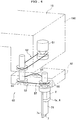
FIG.4 is a schematic perspective view showing a motion of an electricity generating device. -
FIG. 5 is a block diagram showing a relationship between the sensor unit and a main body control unit. -
FIGS.6A and 6B are views illustrating a modified example of the first embodiment of the present invention, whereFIG.6A is a perspective view showing an example which adopts a photoelectric conversion means, andFIG.6B is a block diagram showing an example which adopts wireless power transmission. -
FIGS.7A and 7B are schematic views for explaining a local rotational movement of the X-ray imaging member when an arm of the radiographic X-ray equipment inFIG.1 occupies one revolution position, whereFIG. 7A is a top plan view andFIG. 7B is a front view. -
FIG. 8 is a top plan view in a schematic view showing main parts for explaining the revolving movement and the local rotational movement when CT imaging is performed by the radiographic X-ray equipment inFIG.1 . -
FIG.9 is a view illustrating a first modified example of the first embodiment of the present invention and corresponding toFIG.7A . -
FIGS.10A and 10B are views illustrating a second embodiment of the present invention, whereFIG.10A corresponds toFIG.7A andFIG.10B corresponds toFIG.7B . -
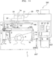
FIG.11 is a front view showing an example of application, in the case where the local movement is an arc movement, of an X-ray imaging member according to a third embodiment of the present invention. -
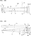
FIGS.12A and 12B are enlarged views showing main parts in the third embodiment of the present invention, whereFIG.12A is a front view andFIG.12B is a side view. -
FIGS.13A to 13C are bottom views showing motions of the arc movement means according to the third embodiment of the present invention, whereFIG.13A shows a position at one end in the arc movement range of the arc movement means,FIG.13B shows a position at the center therein, andFIG.13C shows a position at another end there in. -
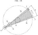
FIG.14 is a plan view showing a motion of the X-ray imaging member according to the third embodiment of the present invention. - Herein after, a first embodiment of the present invention will be described with reference to
FIGS.1 to 8 . - Referring to
FIG.1 ,radiographic X-ray equipment 1 according to the first embodiment is used, with a target as human, in dental examination as medical care. - The
radiographic X-ray equipment 1 is provided with amain body apparatus 200, a supportingapparatus 300 having aframe 310 which supports themain body apparatus 200, a mainbody control unit 400 provided on the supportingapparatus 300, and a transmitting and receiving device 4that communicates with themain body apparatus 200 and the main body control unit400. - The supporting
apparatus 300 is set up on a structure (not shown) in which theradiographic X-ray equipment 1 is placed, and theframe 310 is adapted to support themain body apparatus 200 position-adjustably in an up-and-down direction in the supportingapparatus 300. As another example, themain body apparatus 200 may be provided with a mechanism for making itself position-adjustable relative to theframe 310 in the up-and-down direction. - The
main body apparatus 200 is provided with an X-ray irradiating member 10that irradiates a subject K (for example, dental arch, cephalic part including the dental arch) with an X-ray flux Xa, anX-ray imaging member 7 with an acceptance surface7a provided for receiving the X-ray flux Xa transmitted through the subject K, anarm 15 as a supporting member that supports theX-ray irradiating member 10 and theX-ray imaging member 7 which are arranged across the subject K in their radiation direction of the X-ray flux Xa from theX-ray irradiating member 10, a revolution driving device 20that revolves thearm 15 to cause the X-ray irradiating member10 and theX-ray imaging member 7 to perform a revolving movement around the subject K with a revolution center line La as the center, an imaging-side driving device 30 and arotation mechanism 50 that cause the X-ray imaging member7 as a driven member to perform a local rotational movement which is a rotational movement as a local movement different from the revolving movement, an electricity storing means2that stores electric power required for driving theX-ray imaging member 7, agenerator 3 which is an electric power supplying means that supplies electric power to the electricity storing means 2, and adata detection circuit 71 that detects image data acquired by theX-ray imaging member 7. Here, therevolution driving device 20, a secondary driving device constituted by the imaging-side driving device 30 and therotation mechanism 50 in this embodiment, and a drivingmember 13 as described later, constitute a driving device of theradiographic X-ray equipment 1. - The transmitting and receiving device 4is provided with a sensor unit transmitting and receiving device4a provided in the
main body apparatus 200, and a main body transmitting and receiving device4b provided in the mainbody control unit 400, and is adapted to wirelessly communicate data between the main body control unit 400 (image processing device) and thedata detection circuit 71. - In the
main body apparatus 200, for convenience, the unit that includes theX-ray imaging member 7, the electricity storing means 2, thegenerator 3 which is an electric power supplying means, thedata detection circuit 71 and the sensor unit transmitting and receivingdevice 4a, is referred to as a sensor unit 210 (seeFIG.5 ) . - The
X-ray irradiating member 10 which is supported by an irradiating-side supporting portion 15b of thearm 15 includes anX-ray radiating member 11 having anX-ray source 11a that radiates X-rays, and aslit member 12 as an X-ray flux forming member that forms X-ray flux from theX-ray source 11a into a slit-shaped X-ray flux Xa. Theslit member 12 includes a radiation unit which is constituted by acollimator 12c that defines their radiation range and irradiation direction of the X-ray flux Xa, and aslit 12a that allows the X-ray flux formed by thecollimator 12c to pass there through. Accordingly, thecollimator 12c and theslit 12a from which the X-ray flux Xa is radiated, and theacceptance surface 7a, are located at positions across the subject K in their radiation direction of the X-ray flux Xa in the arm 15 (see alsoFIGS.7A and 7B ). - The
X-ray radiating member 11 and theslit member 12 are provided on thearm 15 and driven by the drivingmember 13 that is controlled by the mainbody control unit 400, so as to perform a rotational movement or a linear movement to be movable relative to thearm 15. - More specifically, the driving
member 13 causes theX-ray source 11a, thecollimator 12c and theslit 12a to move to follow theacceptance surface 7a which performs the local rotational movement, while keeping the state in which theX-ray source 11a, thecollimator 12c, theslit 12a, the subject K and theacceptance surface 7a are positioned in alignment with one another. In the present embodiment, the drivingmember 13 causes theX-ray source 11a, thecollimator 12c and theslit 12a to perform the rotational movement with a radiation center line Lb which passes through theX-ray source 11a and is parallel with the revolution center line La, as the center, thereby causing theX-ray source 11a, thecollimator 12c and theslit 12a to move in the form of an arc or in the circumferential direction. As another example, the drivingmember 13 may cause theX-ray source 11a, thecollimator 12c and theslit 12a to perform the linear movement. - The
X-ray imaging member 7 having theacceptance surface 7a is a two-dimensional X-ray imaging member that is constituted by an image sensor such as CMOS sensor, CdTe sensor or CCD sensor, and is a CMOS sensor as an example in the embodiment described below. - As shown in
FIGS.2A and 2B , theacceptance surface 7a has an elongated shape in which a width W1in its longitudinal direction is greater than a width W2in the direction perpendicular to the longitudinal direction. With theX-ray imaging member 7 being supported by thearm 15, the longitudinal direction of theacceptance surface 7a is a direction nearly parallel with the revolution center line La in the first embodiment. - Note that in the description and the claims, the expression "nearly" includes the case where there is no modifying word "nearly", and also means the scope with which there is no significant difference with respect to the operation and advantageous effects as compared to the case where there is no modifying word "nearly", although not strictly identical to the case where there is no modifying word "nearly".
- Referring to
FIG.1 , therevolution driving device 20 is provided with aservo motor 21 as an actuator for revolution that is provided in theframe 310 and rotates thearm 15, an XY table 22 as a two-dimensional driving device that is rotationally driven by theservo motor 21 and moves thearm 15 on the horizontal plane as a two-dimensional plane which is perpendicular to the revolution center line La, atransmission mechanism 23 that includes a speed reduction mechanism and transmits driving force of theservo motor 21 to the XY table 22, and a connectingshaft 24 as a connecting part that connects theservo motor 21 to thearm 15 via thetransmission mechanism 23 and the XY table 22. Thearm 15 is rotationally driven by theservo motor 21 via thetransmission mechanism 23, the XY table 22 and the connectingshaft 24, so as to rotate with the revolution center line La as the center to thereby revolve theX-ray irradiating member 10 and the X-ray imaging member7. - Here, the "revolution" includes the case of making one or more revolutions and the case of making less than one revolution, with the revolution center line La as the center. Moreover, the speed reduction mechanism included in the
transmission mechanism 23, speed reduction mechanisms included intransmission mechanisms FIGS.2A and 2B ) are constituted by, for example, a worm gear mechanism. - Referring to
FIG.1 ,FIGS.2A and 2B , the imaging-side driving device 30 provided on thearm 15 is provided with aservo motor 31 which is an imaging-side actuator, a holdingmember 32 that holds theX-ray imaging member 7, and atransmission mechanism 33 that includes a speed reduction mechanism and transmits driving force of theservo motor 31 to the holdingmember 32. TheX-ray imaging member 7 and theacceptance surface 7a are rotationally driven by theservo motor 31 via thetransmission mechanism 33 and the holdingmember 32, so as to perform a local rotational movement (seeFIGS.7A and 7B ) with a rotation center line Lc which is a straight line other than the revolution center line La, as the center. - Referring to
FIGS. 7A and 7B additionally, the local rotational movement is defined based on a distance d1 between the rotation center line Lc and theX-ray imaging member 7 in the radial direction with the rotation center line Lcas the center, or a predetermined distance d2as described later, and becomes a movement within the range of a movement width Mw in a predetermined direction when the predetermined direction is defined by a circumferential direction with the revolution center line La (seeFIG.1 ) as the center. The width W2, which is a width of theacceptance surface 7a in the circumferential direction which is the predetermined direction, is smaller than the movement width Mw. Also, in the local rotational movement, theacceptance surface 7 a rotates with its longitudinal direction being nearly parallel with the revolution center line La, accordingly with an elongated state in the revolution center line direction (also in the up-and-down direction in this embodiment) which is a direction parallel with the revolution center line La. - Moreover, when the X-ray imaging member 7makes one revolution around the rotation center line Lc relative to the
arm 15, the rotation center line Lc is arranged so that the subject K is positioned at all times between theslit 12a of theX-ray irradiating member 10 and theacceptance surface 7a of theX-ray imaging member 7 in their radiation direction of the X-ray flux Xa. - Referring to
FIGS. 2A and 2B , the holdingmember 32 is rotatably supported by an imaging-side supporting portion 15c of thearm 15 with the rotation center line Lc as the center, so as to rotate with the rotation center line Lcas the center. Moreover, theX-ray imaging member 7 is rotatably supported by the holdingmember 32 with a rotation center line Le which is a secondary rotation center line positioned at the predetermined distance d2 from the rotation center line Lc, as the center. - More specifically, the holding
member 32 is provided with a first base 41that is rotationally driven by theservo motor 31 via thetransmission mechanism 33,asecond base 42 that rotatably supports theX-ray imaging member 7 with the rotation center line Le as the center and is supported on thefirst base 41 movably in the radial direction of the rotation center line Lc, a connectingmember 43 that connects thefirst base 41 with thesecond base 42 and is extendable in the radial direction of the rotation center line Lc, aservo motor 47 as an actuator for distance adjustment that elongates and contracts the connectingmember 43 in the radial direction of the rotation center line Lc, and the rotation mechanism 50that rotationally drives the X-ray imaging member7 and theacceptance surface 7a with the rotation center line Le as the center. The connectingmember 43 defines the predetermined distance d2 between the rotation center line Lc and the rotation center line Le. - Here, in the present embodiment, the "local movement" is configured inclusive of the local rotational movement (rotation) by the
rotation mechanism 50, and the secondary driving device is configured inclusive of the local rotational movement by the imaging-side driving device 30 and the local rotational movement (rotation) by therotation mechanism 50. - The
rotation mechanism 50 is provided with aservo motor 51 as an actuator for rotation that is rotatably supported by thefirst base 41, atransmission mechanism 52 that includes a speed reduction mechanism, and apower transmission mechanism 53 that is rotationally driven by theservo motor 51 via thetransmission mechanism 52, so as to rotate theX-ray imaging member 7. - Moreover, the power transmission mechanism 53is provided with a driving
pulley 54 as a driving part, a drivenpulley 55 as a driven part which is rotatably supported by thesecond base 42 and to which theX-ray imaging member 7 is provided fixedly, an idle pulley 56which is rotatably supported by thefirst base 41, and abelt 57 as an endless power transmission belt which is stretched over thesepulleys idle pulley 56 is urged by aspring 58 as an urging member, to function as a tensioner which gives tension to thebelt 57. - A rotation center line of the driving
pulley 54 is coaxial with the rotation center line Lc, but may be parallel with the rotation center line Lc in another example. Moreover, a rotation center line of the drivenpulley 55 is the rotation center line Le. - The connecting
member 43 includes a first connectingpart 44 which is provided on thefirst base 41, and a second connectingpart 45 which is provided on thesecond base 42 and is movable linearly relative to the first connectingpart 44 in the radial direction of the rotation center line Lc. In the present embodiment, the first connectingpart 44 is comprised of ascrew rod 44a which is rotatably supported by thefirst base 41 and is rotationally driven by theservo motor 47. Also, the second connectingpart 45 is comprised of afemale screw part 45a into which thescrew rod 44a is screwed, and of a connectingrod 45b which rotatably supports thefemale screw part 45a serving as a connection part for thescrew rod 44a and is fixed on thesecond base 42 to move together with thefemale screw part 45a and the second base 42in the radial direction. - When the
servo motor 47 rotationally drives thescrew rod 44a via a speed reduction mechanism 48as a transmission mechanism, the second connectingpart 45 which is connected via thefemale screw part 45a to thescrew rod 44a rotates and moves along the first connectingpart 44 in the radial direction of the rotation center line Lc, thereby changing the distance d1 and the predetermined distance d2. - Accordingly, the connecting
member 43, theservo motor 47 and thespeed reduction mechanism 48 constitute adistance adjusting mechanism 49 which can change the distance d1 and the predetermined distance d2 between the rotation center line Lc and theacceptance surface 7a of theX-ray imaging member 7. - Therefore, it is possible to change the movement width Mw (see
FIG.7A ) by changing the length of the connectingmember 43 with actuation of the servo motor 47tochange the distance d1 and the predetermined distance d2, and it is possible to change radiographic area on theacceptance surface 7a which performs the local rotational movement without changing a revolution position P (seeFIG.7A ,FIGS.8A and 8B ) of thearm 15. For example, by making the connectingmember 43 longer than the state shown inFIGS. 2A and 2B , the movement width Mw and the radiographic area on theacceptance surface 7a become larger than the movement width Mw and the radiographic area in the case shown inFIG.7A . - Note, in the first embodiment, the length of the connecting
member 43 is constant at an arbitrary position of theX-ray imaging member 7 which performs the local rotational movement, and at an arbitrary revolution position P of thearm 15 which performs the revolving movement. - Referring to
FIGS.7A and 7B additionally, theservo motor 51 directs theacceptance surface 7a toward theslit 12a across the subject K in the radiation direction so that theacceptance surface 7a can receive the X-ray flux Xa transmitted through the subject K at all times. To this end, theservo motor 51 is controlled by amotion control device 60 to thereby rotationally drive the drivingpulley 54 and further rotationally drive the drivenpulley 55, in synchronization with the local rotational movement of theX-ray imaging member 7. Rotational speeds of the drivingpulley 54 and the drivenpulley 55 are set to be equal to each other in this embodiment, but may be set to be different rotational speeds. - The
acceptance surface 7a driven by theservo motor 51 rotates at an arbitrary position on a movement path M (FIG.7A shows a schematic outer circumference of the movement path M) by the local rotational movement so that it becomes parallel with a plane perpendicular to a line which passes through the revolution center line La and the rotation center line Lc when viewed from the revolution center line direction. As another example, theacceptance surface 7a may be rotated to be directed toward the radiation center line Lb at all times. - Moreover, as still another example, a configuration may be adopted in which the
rotation mechanism 50 is provided, in place of theservo motor 51, with a cooperative mechanism (for example, constituted by a gear mechanism) that transmits rotation of theservo motor 31 to the drivingpulley 54, to thereby cause theservo motor 31 to rotationally drive the drivingpulley 54 via the cooperative mechanism, in synchronization with the local rotational movement of theX-ray imaging member 7. This configuration makes it possible to avoid twist of an electric wire of theservo motor 51 by mechanically transmitting the rotation of theservo motor 31, without using theservo motor 51 to which electric power must be supplied. - Accordingly, as shown in
FIGS.7A and 7B , thearm 15 driven by the revolution driving device 20 (seeFIG.1 ) rotates and in the state in which theX-ray irradiating member 10 and theX-ray imaging member 7 occupy the revolution position P, theX-ray imaging member 7 rotates with the rotation center line Lc as the center (FIG.7A shows the positions at intervals of nearly 90°). Moreover, depending on a rotational position of theacceptance surface 7a, theX-ray irradiating member 10 is rotationally driven by the driving member 13 (seeFIG.1 ) in the circumferential direction with the revolution center line La as the center, to move to the position at which theslit 12a and the acceptance surface 7aface each other across the subject K in their radiation direction of the X-ray flux Xa. - The electricity storing means 2 is a charging apparatus which is provided on the
generator 3 as a unit, stores therein electric power generated by thegenerator 3, and supplies the electric power to theX-ray imaging member 7, thedata detection circuit 71 and the sensor unit transmitting and receivingdevice 4a which are provided in the sensor unit 210 (seeFIG.5 ). As the charging apparatus, a rechargeable storage cell can be appropriately adopted, such as a rechargeable lithium-ion battery (lithium-ion storage cell), an electric double layer capacitor, a nickel hydride battery, a nickel-cadmium (NiCd) battery or a lead battery. Since the electric double layer capacitor and the lithium-ion storage cell excel especially in the amount of energy per volume, they make it possible to accomplish weight saving and downsizing. - The
generator 3 which is an electric power supplying means is a device that converts rotational energy into electrical energy to supply the electrical energy to the electricity storing means 2, and as shown inFIG. 3 , is provided with ashaft member 3b to which astator 3a is fixed, and arotor 3c which is rotatably attached to theshaft member 3b and is connected with thepulley 55 as a unit. - As shown in
FIG.4 , thegenerator 3 utilizes rotational energy which is used to rotate theX-ray imaging member 7 by theservo motor 51, causes therotor 3c connected with the pulley 55as a unit to rotate around thestator 3a to generate electricity, and supplies the electricity to the electricity storing means 2. - By this configuration, since the
rotor 3c of thegenerator 3, the electricity storing means 2 and theX-ray imaging member 7 are rotated as a unit, it is possible to certainly prevent disconnection and/or bad connection of wires in the case of causing the X-ray imaging member7 to perform the local movement different from the revolving movement. - Note that although the present embodiment adopts the
generator 3 as the electric power supplying means, it is not limited to thegenerator 3. The present embodiment can also adopt a photoelectric conversion means 3' (seeFIG.6A ) that converts light energy into electrical energy, and/or a wirelesspower transmission system 3" (seeFIG.6B ). - As the photoelectric conversion means 3', a photo electric conversion element such as a photodiode, a solar cell or the like, is appropriately adopted.
- The wireless
power transmission system 3" is a system that wirelessly transmits electric power without using a metal contact and/or a connector. As the wirelesspower transmission system 3", various systems making use of a non-contact charging technique utilizing electromagnetic induction and used at close range, an electromagnetic wave resonance technique utilizing resonant induction, a radio wave transmission technique utilizing radio waves to enable a long-distance electric power transmission, and the like, are appropriately adopted depending on the intended use. - The
data detection circuit 71 is a circuit that converts the X-ray flux Xa received at theacceptance surface 7a into image data, and is disposed on theX-ray imaging member 7 as a unit. - The transmitting and receiving device 4is provided with the sensor unit transmitting and receiving
device 4a that is disposed on theX-ray imaging member 7 as a unit in themain body apparatus 200, and the main body transmitting and receivingdevice 4b provided in the mainbody control unit 400, and wirelessly communicates data between the main body control unit 400 (specifically, animage processing device 65 as described later) and the data detection circuit 71.Note that "wireless" means not connecting by means of a cable or the like via a metal contact and/or a connector, and means communicating by means of radio waves and/or infrared rays. - The transmitting and receiving device 4wirelessly transmits image data detected by the
detection circuit 71, from the sensor unit transmitting and receivingdevice 4a disposed on the sensor unit 210 (seeFIG.5 ) in themain body apparatus 200, to the main body transmitting and receivingdevice 4b provided in the mainbody control unit 400, and the transmitted image data is processed in theimage processing device 65. - Moreover, the transmitting and receiving device 4receivesa sampling clock signal (image acquisition signal) at the sensor unit transmitting and receiving
device 4a. More specifically, when the sensor unit transmitting and receivingdevice 4a wirelessly transmits the image data to the main body transmitting and receivingdevice 4b, the main body transmitting and receivingdevice 4b transmits an image acquisition signal (transmission request signal for next image) which informs a receipt of one image, to the sensor unit transmitting and receivingdevice 4a. Then, the sensor unit transmitting and receivingdevice 4a responds to the transmission request signal to transmit the next, second image data to the main body transmitting and receiving device 4b.Thus,the sensor unit transmitting and receivingdevice 4a and the main body transmitting and receivingdevice 4b repeats the transmitting and receiving. - The main body control unit400is provided with a
motion control device 60 that controls therevolution driving device 20, the imaging-side driving device 30 and X-ray imaging of the subject K, animage processing device 65 that processes image data acquired by theX-ray imaging member 7, anoperation unit 68 that is operated by an operator, the main body transmitting and receivingdevice 4b that constitutes the transmitting and receivingdevice 4, and a display unit (not shown) that displays an image detected by theX-ray imaging member 7. - The
motion control device 60 is provided with a detection unit61 including a position detecting means (for example, constituted by an encoder) that detects the revolution position P of theslit 12a and theacceptance surface 7a (accordingly, which is also the revolution position P of the arm 15) and the rotational position (namely, which is the position on the movement path M) of theX-ray imaging member 7 with the rotation center line Lc as the center, respectively, and a motion control unit 62including a central processing unit. Themotion control unit 62 controls actuation of each of theservo motors operation unit 68 and detection signals from thedetection unit 61. - The
image processing device 65 processes image data acquired through X-ray imaging by theX-ray imaging member 7 to generate CT image, panoramic image and cephalic image. - Moreover, performed through the
operation unit 68 are switching of each radiography mode of CT imaging, panoramic radiography and cephalic radiography of the subject K, settings of the predetermined distance d2, an initial revolution position P of thearm 15 at the start of radiography and a shift revolution amount S as described later, and the like. - Next, the motion of the
radiographic X-ray equipment 1 will be described, giving an example of the case of performing CT imaging by means of theradiographic X-ray equipment 1, with reference toFIGS.1 and8 . - When the CT imaging is selected by the
operation unit 68, theslit 12a and theacceptance surface 7a (accordingly, the arm 15) occupy a first shift revolution position Ps1 as the initial revolution position in the circumferential direction of the revolution center line La. At the first shift revolution position Ps1, the X-ray imaging member 7is driven by theservo motor 31 to rotate in the rotational direction(the clockwise direction inFIGS.8A and 8B ) from the first position set as the initial position on the movement path M of the local rotational movement, and moves on the movement path M to make one continuous revolution around the rotation center line Lc. Meanwhile, under control of themotion control device 60, theX-ray imaging member 7 detects the X-ray flux Xa via theacceptance surface 7a to perform X-ray imaging, at every position of predetermined intervals (for example, predetermined rotational angles in the local rotational movement), thereby acquiring a shift image data group comprised of multiple image data at each position on the movement path M. - The
image processing device 65 performs image correction processing for correcting image data acquired at each position on the movement path M, in order to acquire images for a virtualX-ray imaging member 70 as described later, with the first shift revolution position Ps1 as the start, at a plurality of shift revolution positions Ps while theX-ray imaging member 7 makes one or more revolutions with the revolution center line La as the center. - As shown in
FIG.8 , when the virtualX-ray imaging member 70 has aplanate acceptance surface 70a (hereinafter referred to as "virtual acceptance surface 70a") with a circumferential direction width (a width in the predetermined direction) equal to, for example, the movement width Mw, theimage processing device 65 performs image correction processing with respect to image data acquired by theX-ray imaging member 7, based on a scaling rate N calculated by the following formula.
- Here, Na represents a distance between the
X-ray source 11a and an X-ray imaging site in the subject K; Nb represents a distance between theX-ray source 11a and theacceptance surface 7a; and Nc represents a distance between theX-ray source 11a and thevirtual acceptance surface 70a. - Note that, also in the case where the virtual
X-ray imaging member 70 has an arc-shaped acceptance surface 7awith the radiation center line Lb as the center, a CT image can be acquired by a similar image correction processing using the scaling rate N. - Moreover, when the
X-ray imaging member 7 makes one revolution around the rotation center line Lc as the center, theservo motor 21 causes thearm 15 to perform a shift revolution movement in steps of shift revolution amount S, which is smaller than one revolution of the revolution movement, in the revolution direction (the clockwise direction inFIGS.8A and 8B ) so that theslit 12a and theacceptance surface 7a occupy a second shift revolution position Ps2. By the shift revolution movement of thearm 15, theslit 12a and theacceptance surface 7a move from the first shift revolution position Ps1 to the second shift revolution position Ps2. - Here, in the transient duration in which the
slit 12a and theacceptance surface 7a move from the first shift revolution position Ps1 to the second shift revolution position Ps2, theX-ray imaging member 7 continues the local rotational movement without performing a temporary stop and a restart after the temporary stop, but no X-ray imaging is performed. Note that, as another example, the drivingdevices X-ray imaging member 7 to finish X-ray imaging in the revolution range of less than one revolution at the shift revolution position Ps1, and to cause thearm 15 to perform a shift revolving movement to the next shift revolution position Ps in the remaining revolution range of the one revolution. Thus, theX-ray imaging member 7 continues the local rotational movement until the CT imaging is finished. - Referring to
FIG. 8 ,in the shift revolution positions Ps adjacent to each other in the circumferential direction, the shift revolution amount S is set to form an overlap range Mo in which circumferential direction movement ranges Mc (equal to the movement width Mw in this embodiment) of the respective local rotational movements at the adjacent shift revolution positions Ps overlap each other in the circumferential direction. Themotion control device 60 controls theX-ray imaging member 7 to acquire different shift image data groups of the subject K at a plurality of different positions on the movement path M of theX-ray imaging member 7 by the local rotational movement, in the circumferential direction movement range Mc of the local movement at each shift revolution position Ps. - Here, the respective shift revolution amounts S are set to be a value identical to each other in this embodiment, but may be set to be two or more values different from each other in another example.
- The slit12a and the acceptance surface 7amovefrom the first shift revolution position Ps1 to the second shift revolution position Ps2, and further the
slit 12a and theacceptance surface 7a perform a shift revolving movement sequentially in steps of the shift revolution amount S in the revolution direction to make one revolution around the revolution center line La, thereby finishing the CT imaging. - Then, the
image processing device 65 collects the shift image data group at each shift revolution position Ps to generate the entire image. - Note that, also in the case where the
radiographic X-ray equipment 1 performs panoramic radiography and cephalic radiography, theX-ray imaging member 7 that performs the local rotational movement performs the radiography in the same manner as in the CT imaging, at one or more shift revolution positions Ps, by using the XY table 22 as necessary. - Next, description is given of the operation and advantageous effects of the first embodiment configured as described above.
- The
radiographic X-ray equipment 1 is provided with the imaging-side driving device 30 that causes the X-ray imaging member7 which is a driven member to perform the local movement different from the revolving movement of thearm 15, in the movement width Mw of theacceptance surface 7a when the predetermined direction is defined by the circumferential direction relative to the revolution center line La. The width W2of theacceptance surface 7a in the predetermined direction is smaller than the movement width Mw, and the local movement is the local rotational movement with the rotation center line Lc as the center. - According to this configuration, since the width W2 of the
acceptance surface 7a in the predetermined direction is small as compared to the movement width Mw of the local rotational movement of the acceptance surface 7adriven by the imaging-side driving device 30,an inexpensive X-ray imaging member7 can be used as compared to an X-ray imaging member having an acceptance surface of a size corresponding to the movement width Mw, thereby enabling a reduction in cost of theradiographic X-ray equipment 1. - Moreover, since the
X-ray imaging member 7 performs the rotational movement, it is possible to make unnecessary a temporary stop which would be generated when theX-ray imaging member 7 is subjected to an arc movement or a linear movement, and/or an operation for restarting after the temporary stop. As a result, it is possible to decrease acceleration and deceleration which act on theX-ray imaging member 7, and accordingly to reduce inertial force due to the acceleration and deceleration. Consequently, it is possible to reduce vibration of the driven member due to the inertial force and to improve durability of theX-ray imaging member 7 of an elongated shape. Furthermore, it is possible to suppress a decrease in speed due to a temporary stop of theX-ray imaging member 7 for the duration of the start to the end of the X-ray imaging, and/or an operation for restarting, and accordingly to improve an efficiency in X-ray imaging work by speed-up of theX-ray imaging member 7. - When the
X-ray imaging member 7 makes one revolution with the rotation center line Lc as the center, the rotation center line Lc is arranged so that the subject K is positioned at all times between theX-ray irradiating member 10 and the X-ray imaging member 7.Accordingly, at an arbitrary time or in a continuous period in the duration in which theX-ray imaging member 7 makes one revolution with the rotation center line Lc as the center, the X-ray imaging becomes possible by means of theX-ray imaging member 7, which improves an efficiency in the X-ray imaging work - The revolution driving device 20causes the
X-ray irradiating member 10 and theX-ray imaging member 7 to perform the shift revolution movement in steps of the shift revolution amount S, which is smaller than one revolution of the revolution movement, so that theX-ray irradiating member 10 and the X-ray imaging member 7occupy the shift revolution positionsPs1,Ps2.The imaging-side driving device 30causes theX-ray imaging member 7 to perform the local rotational movement at each shift revolution position Ps1,Ps2.The shift revolution positions Ps1,Ps2adjacent to each other in the circumferential direction are positions that form the overlap range Mo in which the circumferential direction movement ranges Mc of the local rotational movement sat the respective positions overlap each other in the circumferential direction. - This makes it possible to perform CT imaging, panoramic radiography and cephalic radiography, using the
X-ray imaging member 7 in which the width of theacceptance surface 7a in the above predetermined direction is smaller than the movement width Mw of theX-ray imaging member 7. - The imaging-
side driving device 30 is provided with the distance adjusting mechanism 49which can change the distance d1between the rotation center line Lc and theacceptance surface 7a of theX-ray imaging member 7. Accordingly, it is possible to change the radiographic area on theacceptance surface 7a by changing the distance d1 between the rotation center line Lc and theX-ray imaging member 7, without changing the shift revolution amount S, which improves convenience of theradiographic X-ray equipment 1. - The
slit member 12 of theX-ray irradiating member 10 includes the collimator 12cthat defines their radiation range and the irradiation direction of the X-ray flux Xa which is irradiated on the subject K, and the collimator 12cmoves to follow theacceptance surface 7a of theX-ray imaging member 7 which performs the local rotational movement, so as to keep the state in which thecollimator 12c, the subject K and theacceptance surface 7a are positioned in alignment with one another. - By this configuration, since the
collimator 12c moves to follow theacceptance surface 7a while keeping the state in which thecollimator 12c, the subject K and theacceptance surface 7a are positioned in alignment with one another, it is possible to accurately direct the X-ray flux Xa in the irradiation range and the irradiation direction defined by thecollimator 12c, toward the subject K and theacceptance surface 7a, and thus to improve accuracy of the radiography. - Moreover, the radiographic X-ray equipment 1a ccording to the first embodiment of the present invention causes the electricity storing means 2, the
X-ray imaging member 7, thedata detection circuit 71 and the sensor unit transmitting and receivingdevice 4a to perform the local movement (rotation movement) as a unit without moving relative to one another, thereby making it possible to certainly prevent disconnection and/or bad connection of wires between the electricity storing means 2 and theX-ray imaging member 7, thedata detection circuit 71 and the sensor unit transmitting and receivingdevice 4a. - Accordingly, the
radiographic X-ray equipment 1 according to the first embodiment of the present invention makes it possible, while causing the X-ray imaging member7 to perform the local movement different from the revolving movement to thereby acquire a broad acceptance surface and accomplish cost reduction of theradiographic X-ray equipment 1, to suppress generation of bad connection of a cable and/or noises in the case of causing the X-ray imaging member7 to perform the local movement different from the revolving movement, and to accomplish improvement in reliability and durability. - In addition, the
radiographic X-ray equipment 1 according to the first embodiment of the present invention wirelessly performs transmitting and receiving between thedata detection circuit 71 and the main body control unit400,thereby making it possible to comprehensively suppress generation of bad connection of a cable and/or noises and to ensure high reliability and durability. - A modified example of the first embodiment and a second embodiment will be hereinafter described with reference toFIGS.9,10A and 10B.The second embodiment differs from the first embodiment in portions of the configuration and has basically the same configuration as to the other portions. Accordingly, description of the same portion is omitted or simplified, and description is given focusing on different portions. Note that, as to the same member as or the member corresponding to the member in the first embodiment, the same reference sign has been used as necessary.
- According to the modified example of the first embodiment and the second embodiment, it is possible to accomplish the like operation and advantageous effects as in the first embodiment, based on the like configuration as in the first embodiment.
- Referring to
FIGS.2A, 2B and9 , in theX-ray imaging member 7 of aradiographic X-ray equipment 11 according to a first modified example of the first embodiment, theservo motor 47 of thedistance adjusting mechanism 49 is controlled by themotion control device 60 to change the length of the connecting member 43to thereby change the distance d1 and the predetermined distance d2, depending on the position on the movement path M of theX-ray imaging member 7 by the local rotational movement. This makes the local rotational movement of theX-ray imaging member 7, for example, a circular movement which is flattened in the radial direction or in the irradiation direction with the revolution center line La as the center. This flattened circular movement includes, for example, an elliptic movement and an oval movement. Here, the oval movement is, unlike the elliptic movement, a movement comprised of a pair of nearly linear movements which face each other across the rotation center line Lc in the radial direction with the revolution center line La as the center, and of a pair of nearly semicircular movements which link to the pair of nearly linear movements, respectively, and face each other in the circumferential direction with the revolution center line La as the center. - Moreover, the distance d1 and the predetermined distance d2 are changed by the
distance adjusting mechanism 49 depending on the position on the movement path M, thereby making it possible to set the movement path M according to a shape of the subject K. - Thus, the distance adjusting mechanism 49changes the distance d1 or the predetermined distance d2 depending on the position of the X-ray imaging member 7on the movement path M, thereby making it possible to make the distance d1 or the predetermined distance d2 between the subject K and the
X-ray imaging member 7 different depending on the position of the X-ray imaging member 7on the movement path M, during the local rotational movement of theX-ray imaging member 7 or the revolving movement thereof. Accordingly, setting of the movement path M according to a shape of the subject K becomes possible and convenience of the radiography is improved. - Moreover, by making the local rotational movement of the
X-ray imaging member 7 the circular movement which is flattened in the irradiation direction, it is possible to reduce a fluctuating range of the scaling rate N for correcting image data acquired by theX-ray imaging member 7 and accordingly an improvement in accuracy of the radiography becomes possible. - The second embodiment will be described with reference to
FIGS.10A and 10B . - In
radiographic X-ray equipment 102 according to the second embodiment, the rotation center line Lc of the local rotational movement is nearly parallel with a specific line Lp (FIG.10A shows, as an example, a specific line Lp nearly perpendicular to a plane which contains the revolution center line La and theX-ray source 11a)which is parallel with an orthogonal line as a crossed line intersecting with the revolution center line La (namely, a line perpendicular to the revolution center line La).Accordingly, in the local rotational movement, theacceptance surface 7a rotates with its longitudinal direction being nearly parallel with the specific line Lp, accordingly with an elongated state in the orthogonal direction relative to the revolution center line La. - Moreover, in the
radiographic X-ray equipment 102, the predetermined direction is the revolution center line direction and accordingly the movement width Mw of the local rotational movement is the width in the revolution center line direction. Also, the circumferential direction movement range Mc is equal to the width in the circumferential direction of theacceptance surface 7a, in this example, the width W1in its longitudinal direction. - Referring toFIGS.10A and 10B, the
radiographic X-ray equipment 102 of the second embodiment corresponds to the first embodiment and is provided with, as the secondary driving device, an imaging-side driving device 302 having basically the same configuration as the imaging-side driving device 30 (seeFIGS.2A and 2B ) in the first embodiment. The imaging-side driving device 302 causes theX-ray imaging member 7 to perform the local rotational movement with the rotation center line Lc which is nearly parallel with the specific line Lp, as the center. - Hereinafter, description is given of modified configuration of embodiments which could be implemented by modifying portions of the configuration of the embodiments described above.
- The time of radiography by the radiographic X-ray equipment may be a time at which the revolution angle by the revolving movement of the
arm 15 is 180° or less. - When the driven member makes one revolution with the rotation center line Lc as the center, the rotation center line Lc may be arranged so that the subject K is positioned between the
X-ray irradiating member 10 and theX-ray imaging member 7 only in a limited range of less than one revolution. - In the second embodiment, the crossed line intersecting with the revolution center line La may intersect with the revolution center line La in the form other than the orthogonal.
- The up porting member supporting the
X-ray irradiating member 10 and theX-ray imaging member 7 may be constituted by separate supporting bodies that support theX-ray irradiating member 10 and theX-ray imaging member 7, respectively. Moreover, in this case, the revolution center line La may be set separately for theX-ray irradiating member 10 and theX-ray imaging member 7. - The radiographic X-ray equipment may be used in medical care other than dental examination. Moreover, the target may be an object other than human and accordingly the radiographic X-ray equipment may be used in examination of the object.
- The third embodiment differs from the first embodiment and the second embodiment in which the local movement is a rotational movement, in that the local movement is an arc-shaped reciprocating movement (arc movement). Likewise even in the case of arc movement, the generator 3 (see
FIG.11 ) converts rotational energy by the arc movement into electrical energy to make it possible to drive theX-ray imaging member 7 and the like. - Accordingly, in the description below, description is given of constituent elements primarily associated with the arc movement different from the first embodiment, and the like constituent element as in the first embodiment is given the same reference sign and detailed description thereof is omitted.
- As shown in
FIG. 11 , radiographic X-ray equipment l'according to the third embodiment is provided with anX-ray radiating member 11 having anX-ray source 11a,aslit member 12 that forms X-ray flux from theX-ray source 11a into a slit-shaped X-ray flux Xa, an X-ray imaging member 7that detects the X-ray flux Xa, anarc movement arm 120 that supports theX-ray radiating member 11 and theX-ray imaging member 7, a revolution driving device 20that causes thearc movement arm 120 to rotate around the revolution center line La, an arc movement means 130 by a cam mechanism that causes theX-ray imaging member 7 to perform an arc movement around an arc movement center axis Ld, and a motion control device 60' that controls motions of therevolution driving device 20 and the arc movement means 130 by the cam mechanism. - The
X-ray imaging member 7 is provided on the arc movement arm 120and in the same manner as the first embodiment, the sensor unit transmitting and receivingdevice 4a and thedata detection circuit 71 are provided on theX-ray imaging member 7 as a unit. - The
arc movement arm 120 is rotatably supported by ashaft member 121 arranged on the arc movement center axis Ld. The arc movement center axis Ld is arranged coaxially with theX-ray radiating member 11 provided on thearc movement arm 120. - Moreover, the
generator 3 is attached to theshaft member 121 arranged on the arc movement center axis Ld, and the electricity storing means 2 is provided on thearc movement arm 120. - As shown in
FIG.12B , the arc movement means 130 by the cam mechanism is provided with acam roller 132 which is connected to aservo motor 131 and is rotatably supported, acamgroove 133 which is formed on the outer periphery of thecam roller 132, and a camp in 134 which is engaged to move along thecamgroove 133. - The camp in 134 is fixed to project from the
arc movement arm 120. Moreover, the arc movement means 130 by the cam mechanism is provided on anarm 150 so that the camp in 134 is engaged with thecamgroove 133. - By this configuration, as shown in
FIGS.13A to 13C , the radiographic X-ray equipment l'according to the third embodiment causes theservo motor 131 to rotate thecam roller 132 in an R direction to thereby rotate thearc movement arm 120 with the arc movement center axis Ld as the center and cause theX-ray imaging member 7 toper form the arc movement in an arc movement range δ(FIG.13A ) so as to detect the X-ray flux Xa transmitted through the subject K, thereby making it possible to have theX-ray imaging member 7 function as a broad two-dimensional X-ray imaging member in the arc movement range δ. - Moreover, since the
generator 3 attached to theshaft member 121 arranged on the arc movement center axis Ld, the electricity storing means 2 and theX-ray imaging member 7 perform the arc movement as a unit, it is possible to certainly prevent disconnection and/or bad connection of wires by driving theX-ray imaging member 7 with the electricity storing means 2. - Note that although in the third embodiment too, description has been given of the example adopting the
generator 3 as the electric power supplying means, it is also possible to adopt the photoelectric conversion means 3'and/or the wirelesspower transmission system 3"in the same manner as the first embodiment. - Moreover, although the
radiographic X-ray equipment 1 and the like according to the present invention supplies electric power from the electric power supplying means such as thegenerator 3 to the electricity storing means 2to thereby suppress bad connection or the like of a cable in the case of causing theX-ray imaging member 7 to perform a local movement different from a revolving movement, the present invention is not limited to the electric power supplying means such as thegenerator 3, nor limited to the time of radiography. For example, a configuration maybe adopted in which the mainbody control unit 400 and the electricity storing means 2 are wired to be able to be disconnected from each other (by a switching circuit, manual operation or the like),and at the time of non-radiography, an external power source or the like that supplies electric power to the mainbody control unit 400 is used to charge the electricity storing means 2, and at the time of radiography, the external power source or the like that supplies electric power to the mainbody control unit 400, and the electricity storing means 2 are disconnected from each other to prevent twist of a cable and/or noises. -
- 1, 1', 11, 102
- Radiographic X-ray equipment
- 2
- Electricity storing means
- 3
- Generator
- 3'
- Photoelectric conversion means
- 3"
- Wireless power transmission system
- 4
- Transmitting and receiving device
- 4a
- Sensor unit transmitting and receiving device
- 4b
- Main body transmitting and receiving device
- 7
- X-ray imaging member
- 7a
- Acceptance surface
- 10
- X-ray irradiating member
- 13
- Driving member
- 15
- Arm
- 20
- Revolution driving device
- 22
- XY table
- 30, 302
- Imaging-side driving device
- 60, 60'
- Motion control device
- 61
- Detection unit
- 62
- Motion control unit
- 65
- Image processing device
- 68
- Operation unit
- 200
- Main body apparatus
- 210
- Sensor unit
- 300
- Supporting apparatus
- 400
- Main body control unit
- La
- Revolution center line
- Lc
- Rotation center line
- M
- Movement path
- Mw
- Movement width
- Ps
- Shift revolution position
- S
- Shift revolution amount
- Mc
- Circumferential direction movement range
- Mo
- Overlap range
- K
- Subject
- Xa
- X-ray flux
Claims (4)
- Radiographic X-ray equipment (1, 1', 11, 102) including an X-ray irradiating member (10) that irradiates a subject (K) with an X-ray flux (Xa), an X-ray imaging member (7) with an acceptance surface (7a) provided for receiving the X-ray flux (Xa) transmitted through the subject (K), a revolution driving device (20) that causes the X-ray irradiating member (10) and the X-ray imaging member (7) to perform a revolving movement around the subject (K) with a revolution center line (La) as the center, and a main body control unit (400) that controls the revolution driving device (20), the radiographic X-ray equipment (1, 1', 11, 102) comprising:a secondary driving device that is controlled by the main body control unit (400) to cause the X-ray imaging member (7) to perform a local movement different from the revolving movement, with a movement width (Mw) in a predetermined direction;an electricity storing means (2) that stores electric power to be supplied to the X-ray imaging member (7); andan electric power supplying means (3) that supplies electric power to the electricity storing means (2),the X-ray imaging member (7) and the electricity storing means (2) being connected to each other, and the secondary driving device causing the electricity storing means (2) and the X-ray imaging member (7) to perform the local movement as a unit without moving relative to each other,characterized in that
the electric power supplying means (3) includes an electricity generating means that is connected by wire with the electricity storing means (2), and
the electricity generating means is provided at a position to perform a local movement as a unit without moving relative to the electricity storing means (2) and the X-ray imaging member (7), wherein the local movement is a rotational movement, and
the electricity generating means utilizes a rotational force by the rotational movement to generate electricity. - The radiographic X-ray equipment (1, 1', 11, 102) according to claim 1, wherein the electric power supplying means (3) includes a wireless power transmission device (3") that wirelessly transmits electric power to the electricity storing means (2).
- The radiographic X-ray equipment (1, 1', 11, 102) according to claim 1, wherein the electricity generating means includes a photoelectric conversion means (3') that converts light energy into electrical energy.
- The radiographic X-ray equipment (1, 1', 11, 102) according to any one of claims 1 to 3, further comprising:a data detection circuit (71) that detects an X-ray flux (Xa) received by the X-ray imaging member (7), as image data;an image processing device (65) that is provided in the main body control unit (400) and processes the image data detected by the data detection circuit (71); anda transmitting and receiving device (4) that wirelessly communicates data between the image processing device (65) and the data detection circuit (71).
Applications Claiming Priority (2)
| Application Number | Priority Date | Filing Date | Title |
|---|---|---|---|
| JP2012034925A JP5746990B2 (en) | 2012-02-21 | 2012-02-21 | X-ray equipment |
| PCT/JP2013/052946 WO2013125361A1 (en) | 2012-02-21 | 2013-02-07 | X-ray imaging apparatus |
Publications (3)
| Publication Number | Publication Date |
|---|---|
| EP2818114A1 EP2818114A1 (en) | 2014-12-31 |
| EP2818114A4 EP2818114A4 (en) | 2015-11-11 |
| EP2818114B1 true EP2818114B1 (en) | 2017-10-25 |
Family
ID=49005549
Family Applications (1)
| Application Number | Title | Priority Date | Filing Date |
|---|---|---|---|
| EP13751245.5A Not-in-force EP2818114B1 (en) | 2012-02-21 | 2013-02-07 | X-ray imaging apparatus |
Country Status (4)
| Country | Link |
|---|---|
| US (1) | US9510795B2 (en) |
| EP (1) | EP2818114B1 (en) |
| JP (1) | JP5746990B2 (en) |
| WO (1) | WO2013125361A1 (en) |
Families Citing this family (13)
| Publication number | Priority date | Publication date | Assignee | Title |
|---|---|---|---|---|
| JP6370297B2 (en) * | 2012-09-07 | 2018-08-08 | トロフィー | Device for partial CT imaging |
| WO2015125589A1 (en) * | 2014-02-21 | 2015-08-27 | 株式会社テレシステムズ | X-ray imaging apparatus |
| JP6521648B2 (en) * | 2014-02-26 | 2019-05-29 | タカラテレシステムズ株式会社 | X-ray imaging device |
| KR20150130795A (en) * | 2014-05-14 | 2015-11-24 | 주식회사바텍 | X-ray photographing apparatus using power supply by wireless |
| WO2016135526A1 (en) * | 2015-02-27 | 2016-09-01 | Trophy | Bite block for cbct imaging device |
| JP6476013B2 (en) * | 2015-02-27 | 2019-02-27 | 日本光電工業株式会社 | Slide device for medical device |
| US9820708B2 (en) * | 2015-03-30 | 2017-11-21 | Medtronic Navigation, Inc. | Apparatus and method for mechanically providing power to a generator on a continuous rotatable rotor of an X-ray scanner |
| CN107638185B (en) * | 2016-07-21 | 2024-03-22 | 瑞地玛医学科技有限公司 | A C-arm imaging system |
| CN107773258A (en) * | 2016-08-31 | 2018-03-09 | 通用电气公司 | X-ray imaging device and X-ray imaging system |
| JP6894870B2 (en) * | 2018-06-08 | 2021-06-30 | 株式会社モリタ製作所 | X-ray CT imaging device |
| DE102018222595A1 (en) * | 2018-12-20 | 2020-06-25 | Siemens Healthcare Gmbh | Process for image processing of an image data set of a patient, medical imaging device, computer program and electronically readable data carrier |
| JP7324505B2 (en) * | 2019-11-18 | 2023-08-10 | 株式会社吉田製作所 | X-ray dose control system and X-ray dose control method |
| JP2024098329A (en) * | 2023-01-10 | 2024-07-23 | 株式会社島津製作所 | X-ray imaging device and subject holding mechanism |
Family Cites Families (10)
| Publication number | Priority date | Publication date | Assignee | Title |
|---|---|---|---|---|
| JP3807833B2 (en) | 1996-12-10 | 2006-08-09 | 株式会社モリタ製作所 | X-ray equipment |
| JP3650515B2 (en) * | 1997-09-30 | 2005-05-18 | 株式会社モリタ製作所 | Digital sensor cassette for panoramic X-ray equipment |
| EP0904734A3 (en) * | 1997-09-30 | 2000-03-29 | Kabushikikaisha Morita Seisakusho | Panoramic radiographic apparatus and digital sensor cassette used for same apparatus |
| JP2003175031A (en) | 2001-10-02 | 2003-06-24 | Morita Mfg Co Ltd | Digital X-ray panoramic imaging device |
| JP2008134057A (en) | 2005-03-10 | 2008-06-12 | Konica Minolta Medical & Graphic Inc | Radiation image detector and radiation image photographing system |
| WO2011027381A1 (en) * | 2009-09-01 | 2011-03-10 | 株式会社島津製作所 | Mobile radiation imaging device |
| JP5758617B2 (en) * | 2010-02-23 | 2015-08-05 | 富士フイルム株式会社 | Radiation imaging apparatus and power supply method for radiation imaging apparatus |
| US8798236B2 (en) | 2010-01-29 | 2014-08-05 | Fujifilm Corporation | Radiographic image capturing apparatus and radiographic image capturing system |
| JP2012029844A (en) * | 2010-07-30 | 2012-02-16 | Fujifilm Corp | Moving power source vehicle and power supply method |
| JP5395958B2 (en) * | 2010-08-09 | 2014-01-22 | 株式会社吉田製作所 | X-ray equipment |
-
2012
- 2012-02-21 JP JP2012034925A patent/JP5746990B2/en not_active Expired - Fee Related
-
2013
- 2013-02-07 WO PCT/JP2013/052946 patent/WO2013125361A1/en not_active Ceased
- 2013-02-07 EP EP13751245.5A patent/EP2818114B1/en not_active Not-in-force
- 2013-02-07 US US14/378,508 patent/US9510795B2/en not_active Expired - Fee Related
Non-Patent Citations (1)
| Title |
|---|
| None * |
Also Published As
| Publication number | Publication date |
|---|---|
| US20150036800A1 (en) | 2015-02-05 |
| WO2013125361A1 (en) | 2013-08-29 |
| EP2818114A1 (en) | 2014-12-31 |
| JP2013169329A (en) | 2013-09-02 |
| US9510795B2 (en) | 2016-12-06 |
| EP2818114A4 (en) | 2015-11-11 |
| JP5746990B2 (en) | 2015-07-08 |
Similar Documents
| Publication | Publication Date | Title |
|---|---|---|
| US9510795B2 (en) | Radiographic X-ray equipment | |
| EP2863803B1 (en) | Multi-plane x-ray imaging system and method | |
| US6428206B1 (en) | X-ray diagnostic imaging apparatus | |
| EP2599439B1 (en) | X-ray CT imaging device | |
| JP6927049B2 (en) | Motor and motor manufacturing method | |
| JP4481392B2 (en) | X-ray diagnostic equipment | |
| KR101838420B1 (en) | X-ray device having an adjusting apparatus | |
| US20120069960A1 (en) | Portable radiation imaging system, portable radiation source holder used therein, and set of instruments for radiation imaging | |
| JPWO2010150719A1 (en) | X-ray equipment | |
| JP2010035984A (en) | X-ray imaging apparatus | |
| CN102835971A (en) | CT (computed tomography) scanning device, rotary CT system and examination method | |
| CN107982646B (en) | A CBCT reconstruction method and radiotherapy device | |
| WO2014024887A1 (en) | X-ray image capture device | |
| JP2012050562A (en) | Radiation image capturing apparatus, radiation image capturing method, and program | |
| CN109091159B (en) | Portable limb joint cone beam CT imaging system | |
| CN103637761A (en) | Internal robot for gastrointestinal tract | |
| KR20100043334A (en) | A dental x-ray equipment | |
| JP6068081B2 (en) | X-ray computed tomography system | |
| JP2004141656A (en) | Tomography equipment | |
| KR102023025B1 (en) | X-ray photographing apparatus | |
| JP2011004857A (en) | Radiographic imaging system | |
| CN106659445A (en) | X-ray photographing apparatus adopting wireless power supply manner | |
| JP2014064958A (en) | X-ray imaging apparatus, c-arm imaging apparatus, control method and program | |
| CN211409114U (en) | X-ray beam limiting device and X-ray diagnostic device | |
| KR20120090290A (en) | Medical radiography system |
Legal Events
| Date | Code | Title | Description |
|---|---|---|---|
| PUAI | Public reference made under article 153(3) epc to a published international application that has entered the european phase |
Free format text: ORIGINAL CODE: 0009012 |
|
| 17P | Request for examination filed |
Effective date: 20140916 |
|
| AK | Designated contracting states |
Kind code of ref document: A1 Designated state(s): AL AT BE BG CH CY CZ DE DK EE ES FI FR GB GR HR HU IE IS IT LI LT LU LV MC MK MT NL NO PL PT RO RS SE SI SK SM TR |
|
| AX | Request for extension of the european patent |
Extension state: BA ME |
|
| DAX | Request for extension of the european patent (deleted) | ||
| RA4 | Supplementary search report drawn up and despatched (corrected) |
Effective date: 20151012 |
|
| GRAP | Despatch of communication of intention to grant a patent |
Free format text: ORIGINAL CODE: EPIDOSNIGR1 |
|
| STAA | Information on the status of an ep patent application or granted ep patent |
Free format text: STATUS: GRANT OF PATENT IS INTENDED |
|
| RIC1 | Information provided on ipc code assigned before grant |
Ipc: A61B 6/14 20060101AFI20170315BHEP Ipc: A61B 6/02 20060101ALI20170315BHEP Ipc: A61B 6/00 20060101ALI20170315BHEP Ipc: A61B 6/03 20060101ALI20170315BHEP Ipc: A61B 6/06 20060101ALI20170315BHEP |
|
| INTG | Intention to grant announced |
Effective date: 20170406 |
|
| RIN1 | Information on inventor provided before grant (corrected) |
Inventor name: TAKEMOTO, TERUMI Inventor name: TOMOE, TAKESHI |
|
| GRAJ | Information related to disapproval of communication of intention to grant by the applicant or resumption of examination proceedings by the epo deleted |
Free format text: ORIGINAL CODE: EPIDOSDIGR1 |
|
| STAA | Information on the status of an ep patent application or granted ep patent |
Free format text: STATUS: REQUEST FOR EXAMINATION WAS MADE |
|
| INTC | Intention to grant announced (deleted) | ||
| GRAS | Grant fee paid |
Free format text: ORIGINAL CODE: EPIDOSNIGR3 |
|
| STAA | Information on the status of an ep patent application or granted ep patent |
Free format text: STATUS: GRANT OF PATENT IS INTENDED |
|
| GRAP | Despatch of communication of intention to grant a patent |
Free format text: ORIGINAL CODE: EPIDOSNIGR1 |
|
| GRAA | (expected) grant |
Free format text: ORIGINAL CODE: 0009210 |
|
| STAA | Information on the status of an ep patent application or granted ep patent |
Free format text: STATUS: THE PATENT HAS BEEN GRANTED |
|
| INTG | Intention to grant announced |
Effective date: 20170831 |
|
| AK | Designated contracting states |
Kind code of ref document: B1 Designated state(s): AL AT BE BG CH CY CZ DE DK EE ES FI FR GB GR HR HU IE IS IT LI LT LU LV MC MK MT NL NO PL PT RO RS SE SI SK SM TR |
|
| REG | Reference to a national code |
Ref country code: GB Ref legal event code: FG4D |
|
| REG | Reference to a national code |
Ref country code: CH Ref legal event code: EP |
|
| REG | Reference to a national code |
Ref country code: AT Ref legal event code: REF Ref document number: 939122 Country of ref document: AT Kind code of ref document: T Effective date: 20171115 |
|
| REG | Reference to a national code |
Ref country code: IE Ref legal event code: FG4D |
|
| REG | Reference to a national code |
Ref country code: DE Ref legal event code: R096 Ref document number: 602013028420 Country of ref document: DE |
|
| REG | Reference to a national code |
Ref country code: FR Ref legal event code: PLFP Year of fee payment: 6 |
|
| REG | Reference to a national code |
Ref country code: NL Ref legal event code: MP Effective date: 20171025 |
|
| REG | Reference to a national code |
Ref country code: LT Ref legal event code: MG4D |
|
| REG | Reference to a national code |
Ref country code: AT Ref legal event code: MK05 Ref document number: 939122 Country of ref document: AT Kind code of ref document: T Effective date: 20171025 |
|
| PG25 | Lapsed in a contracting state [announced via postgrant information from national office to epo] |
Ref country code: NL Free format text: LAPSE BECAUSE OF FAILURE TO SUBMIT A TRANSLATION OF THE DESCRIPTION OR TO PAY THE FEE WITHIN THE PRESCRIBED TIME-LIMIT Effective date: 20171025 |
|
| PG25 | Lapsed in a contracting state [announced via postgrant information from national office to epo] |
Ref country code: LT Free format text: LAPSE BECAUSE OF FAILURE TO SUBMIT A TRANSLATION OF THE DESCRIPTION OR TO PAY THE FEE WITHIN THE PRESCRIBED TIME-LIMIT Effective date: 20171025 Ref country code: NO Free format text: LAPSE BECAUSE OF FAILURE TO SUBMIT A TRANSLATION OF THE DESCRIPTION OR TO PAY THE FEE WITHIN THE PRESCRIBED TIME-LIMIT Effective date: 20180125 Ref country code: SE Free format text: LAPSE BECAUSE OF FAILURE TO SUBMIT A TRANSLATION OF THE DESCRIPTION OR TO PAY THE FEE WITHIN THE PRESCRIBED TIME-LIMIT Effective date: 20171025 Ref country code: ES Free format text: LAPSE BECAUSE OF FAILURE TO SUBMIT A TRANSLATION OF THE DESCRIPTION OR TO PAY THE FEE WITHIN THE PRESCRIBED TIME-LIMIT Effective date: 20171025 |
|
| PG25 | Lapsed in a contracting state [announced via postgrant information from national office to epo] |
Ref country code: AT Free format text: LAPSE BECAUSE OF FAILURE TO SUBMIT A TRANSLATION OF THE DESCRIPTION OR TO PAY THE FEE WITHIN THE PRESCRIBED TIME-LIMIT Effective date: 20171025 Ref country code: GR Free format text: LAPSE BECAUSE OF FAILURE TO SUBMIT A TRANSLATION OF THE DESCRIPTION OR TO PAY THE FEE WITHIN THE PRESCRIBED TIME-LIMIT Effective date: 20180126 Ref country code: LV Free format text: LAPSE BECAUSE OF FAILURE TO SUBMIT A TRANSLATION OF THE DESCRIPTION OR TO PAY THE FEE WITHIN THE PRESCRIBED TIME-LIMIT Effective date: 20171025 Ref country code: BG Free format text: LAPSE BECAUSE OF FAILURE TO SUBMIT A TRANSLATION OF THE DESCRIPTION OR TO PAY THE FEE WITHIN THE PRESCRIBED TIME-LIMIT Effective date: 20180125 Ref country code: HR Free format text: LAPSE BECAUSE OF FAILURE TO SUBMIT A TRANSLATION OF THE DESCRIPTION OR TO PAY THE FEE WITHIN THE PRESCRIBED TIME-LIMIT Effective date: 20171025 Ref country code: RS Free format text: LAPSE BECAUSE OF FAILURE TO SUBMIT A TRANSLATION OF THE DESCRIPTION OR TO PAY THE FEE WITHIN THE PRESCRIBED TIME-LIMIT Effective date: 20171025 Ref country code: IS Free format text: LAPSE BECAUSE OF FAILURE TO SUBMIT A TRANSLATION OF THE DESCRIPTION OR TO PAY THE FEE WITHIN THE PRESCRIBED TIME-LIMIT Effective date: 20180225 |
|
| REG | Reference to a national code |
Ref country code: DE Ref legal event code: R097 Ref document number: 602013028420 Country of ref document: DE |
|
| PG25 | Lapsed in a contracting state [announced via postgrant information from national office to epo] |
Ref country code: SK Free format text: LAPSE BECAUSE OF FAILURE TO SUBMIT A TRANSLATION OF THE DESCRIPTION OR TO PAY THE FEE WITHIN THE PRESCRIBED TIME-LIMIT Effective date: 20171025 Ref country code: DK Free format text: LAPSE BECAUSE OF FAILURE TO SUBMIT A TRANSLATION OF THE DESCRIPTION OR TO PAY THE FEE WITHIN THE PRESCRIBED TIME-LIMIT Effective date: 20171025 Ref country code: CZ Free format text: LAPSE BECAUSE OF FAILURE TO SUBMIT A TRANSLATION OF THE DESCRIPTION OR TO PAY THE FEE WITHIN THE PRESCRIBED TIME-LIMIT Effective date: 20171025 Ref country code: CY Free format text: LAPSE BECAUSE OF FAILURE TO SUBMIT A TRANSLATION OF THE DESCRIPTION OR TO PAY THE FEE WITHIN THE PRESCRIBED TIME-LIMIT Effective date: 20171025 Ref country code: EE Free format text: LAPSE BECAUSE OF FAILURE TO SUBMIT A TRANSLATION OF THE DESCRIPTION OR TO PAY THE FEE WITHIN THE PRESCRIBED TIME-LIMIT Effective date: 20171025 |
|
| PG25 | Lapsed in a contracting state [announced via postgrant information from national office to epo] |
Ref country code: PL Free format text: LAPSE BECAUSE OF FAILURE TO SUBMIT A TRANSLATION OF THE DESCRIPTION OR TO PAY THE FEE WITHIN THE PRESCRIBED TIME-LIMIT Effective date: 20171025 Ref country code: SM Free format text: LAPSE BECAUSE OF FAILURE TO SUBMIT A TRANSLATION OF THE DESCRIPTION OR TO PAY THE FEE WITHIN THE PRESCRIBED TIME-LIMIT Effective date: 20171025 Ref country code: RO Free format text: LAPSE BECAUSE OF FAILURE TO SUBMIT A TRANSLATION OF THE DESCRIPTION OR TO PAY THE FEE WITHIN THE PRESCRIBED TIME-LIMIT Effective date: 20171025 Ref country code: IT Free format text: LAPSE BECAUSE OF FAILURE TO SUBMIT A TRANSLATION OF THE DESCRIPTION OR TO PAY THE FEE WITHIN THE PRESCRIBED TIME-LIMIT Effective date: 20171025 |
|
| PLBE | No opposition filed within time limit |
Free format text: ORIGINAL CODE: 0009261 |
|
| STAA | Information on the status of an ep patent application or granted ep patent |
Free format text: STATUS: NO OPPOSITION FILED WITHIN TIME LIMIT |
|
| REG | Reference to a national code |
Ref country code: CH Ref legal event code: PL |
|
| PG25 | Lapsed in a contracting state [announced via postgrant information from national office to epo] |
Ref country code: MC Free format text: LAPSE BECAUSE OF FAILURE TO SUBMIT A TRANSLATION OF THE DESCRIPTION OR TO PAY THE FEE WITHIN THE PRESCRIBED TIME-LIMIT Effective date: 20171025 |
|
| 26N | No opposition filed |
Effective date: 20180726 |
|
| GBPC | Gb: european patent ceased through non-payment of renewal fee |
Effective date: 20180207 |
|
| REG | Reference to a national code |
Ref country code: IE Ref legal event code: MM4A |
|
| REG | Reference to a national code |
Ref country code: BE Ref legal event code: MM Effective date: 20180228 |
|
| PG25 | Lapsed in a contracting state [announced via postgrant information from national office to epo] |
Ref country code: LU Free format text: LAPSE BECAUSE OF NON-PAYMENT OF DUE FEES Effective date: 20180207 Ref country code: SI Free format text: LAPSE BECAUSE OF FAILURE TO SUBMIT A TRANSLATION OF THE DESCRIPTION OR TO PAY THE FEE WITHIN THE PRESCRIBED TIME-LIMIT Effective date: 20171025 Ref country code: LI Free format text: LAPSE BECAUSE OF NON-PAYMENT OF DUE FEES Effective date: 20180228 Ref country code: CH Free format text: LAPSE BECAUSE OF NON-PAYMENT OF DUE FEES Effective date: 20180228 |
|
| PG25 | Lapsed in a contracting state [announced via postgrant information from national office to epo] |
Ref country code: IE Free format text: LAPSE BECAUSE OF NON-PAYMENT OF DUE FEES Effective date: 20180207 |
|
| PG25 | Lapsed in a contracting state [announced via postgrant information from national office to epo] |
Ref country code: BE Free format text: LAPSE BECAUSE OF NON-PAYMENT OF DUE FEES Effective date: 20180228 Ref country code: GB Free format text: LAPSE BECAUSE OF NON-PAYMENT OF DUE FEES Effective date: 20180207 |
|
| PG25 | Lapsed in a contracting state [announced via postgrant information from national office to epo] |
Ref country code: MT Free format text: LAPSE BECAUSE OF NON-PAYMENT OF DUE FEES Effective date: 20180207 |
|
| PG25 | Lapsed in a contracting state [announced via postgrant information from national office to epo] |
Ref country code: TR Free format text: LAPSE BECAUSE OF FAILURE TO SUBMIT A TRANSLATION OF THE DESCRIPTION OR TO PAY THE FEE WITHIN THE PRESCRIBED TIME-LIMIT Effective date: 20171025 |
|
| PG25 | Lapsed in a contracting state [announced via postgrant information from national office to epo] |
Ref country code: PT Free format text: LAPSE BECAUSE OF FAILURE TO SUBMIT A TRANSLATION OF THE DESCRIPTION OR TO PAY THE FEE WITHIN THE PRESCRIBED TIME-LIMIT Effective date: 20171025 Ref country code: HU Free format text: LAPSE BECAUSE OF FAILURE TO SUBMIT A TRANSLATION OF THE DESCRIPTION OR TO PAY THE FEE WITHIN THE PRESCRIBED TIME-LIMIT; INVALID AB INITIO Effective date: 20130207 |
|
| PG25 | Lapsed in a contracting state [announced via postgrant information from national office to epo] |
Ref country code: MK Free format text: LAPSE BECAUSE OF NON-PAYMENT OF DUE FEES Effective date: 20171025 |
|
| PG25 | Lapsed in a contracting state [announced via postgrant information from national office to epo] |
Ref country code: AL Free format text: LAPSE BECAUSE OF FAILURE TO SUBMIT A TRANSLATION OF THE DESCRIPTION OR TO PAY THE FEE WITHIN THE PRESCRIBED TIME-LIMIT Effective date: 20171025 |
|
| PGFP | Annual fee paid to national office [announced via postgrant information from national office to epo] |
Ref country code: FI Payment date: 20220217 Year of fee payment: 10 |
|
| PGFP | Annual fee paid to national office [announced via postgrant information from national office to epo] |
Ref country code: FR Payment date: 20220216 Year of fee payment: 10 |
|
| PGFP | Annual fee paid to national office [announced via postgrant information from national office to epo] |
Ref country code: DE Payment date: 20220428 Year of fee payment: 10 |
|
| REG | Reference to a national code |
Ref country code: DE Ref legal event code: R119 Ref document number: 602013028420 Country of ref document: DE |
|
| PG25 | Lapsed in a contracting state [announced via postgrant information from national office to epo] |
Ref country code: FI Free format text: LAPSE BECAUSE OF NON-PAYMENT OF DUE FEES Effective date: 20230207 |
|
| PG25 | Lapsed in a contracting state [announced via postgrant information from national office to epo] |
Ref country code: FR Free format text: LAPSE BECAUSE OF NON-PAYMENT OF DUE FEES Effective date: 20230228 Ref country code: DE Free format text: LAPSE BECAUSE OF NON-PAYMENT OF DUE FEES Effective date: 20230901 |