EP2817709B1 - Three-dimensional printing - Google Patents
Three-dimensional printing Download PDFInfo
- Publication number
- EP2817709B1 EP2817709B1 EP13752184.5A EP13752184A EP2817709B1 EP 2817709 B1 EP2817709 B1 EP 2817709B1 EP 13752184 A EP13752184 A EP 13752184A EP 2817709 B1 EP2817709 B1 EP 2817709B1
- Authority
- EP
- European Patent Office
- Prior art keywords
- components
- computing device
- dimensional
- functionality
- dimensional printing
- Prior art date
- Legal status (The legal status is an assumption and is not a legal conclusion. Google has not performed a legal analysis and makes no representation as to the accuracy of the status listed.)
- Active
Links
- 238000010146 3D printing Methods 0.000 title claims description 37
- 238000000034 method Methods 0.000 claims description 41
- 238000012545 processing Methods 0.000 claims description 28
- 230000007246 mechanism Effects 0.000 claims description 23
- 230000008569 process Effects 0.000 claims description 2
- 238000003860 storage Methods 0.000 description 25
- 238000004891 communication Methods 0.000 description 9
- 239000000463 material Substances 0.000 description 9
- 239000000758 substrate Substances 0.000 description 9
- 230000006870 function Effects 0.000 description 7
- 238000007639 printing Methods 0.000 description 7
- 238000004519 manufacturing process Methods 0.000 description 6
- 230000003287 optical effect Effects 0.000 description 5
- 230000015572 biosynthetic process Effects 0.000 description 4
- 230000003993 interaction Effects 0.000 description 4
- 239000007788 liquid Substances 0.000 description 4
- 230000004044 response Effects 0.000 description 3
- 239000000654 additive Substances 0.000 description 2
- 230000000996 additive effect Effects 0.000 description 2
- 238000010586 diagram Methods 0.000 description 2
- 238000009826 distribution Methods 0.000 description 2
- 238000005516 engineering process Methods 0.000 description 2
- 239000000976 ink Substances 0.000 description 2
- 230000002093 peripheral effect Effects 0.000 description 2
- 229920000642 polymer Polymers 0.000 description 2
- 239000011347 resin Substances 0.000 description 2
- 229920005989 resin Polymers 0.000 description 2
- 238000000110 selective laser sintering Methods 0.000 description 2
- 239000004065 semiconductor Substances 0.000 description 2
- 238000003491 array Methods 0.000 description 1
- 239000011230 binding agent Substances 0.000 description 1
- 230000001413 cellular effect Effects 0.000 description 1
- 230000008859 change Effects 0.000 description 1
- 238000007796 conventional method Methods 0.000 description 1
- 230000008878 coupling Effects 0.000 description 1
- 238000010168 coupling process Methods 0.000 description 1
- 238000005859 coupling reaction Methods 0.000 description 1
- 230000001419 dependent effect Effects 0.000 description 1
- 230000008021 deposition Effects 0.000 description 1
- 238000013461 design Methods 0.000 description 1
- 238000012938 design process Methods 0.000 description 1
- 238000007519 figuring Methods 0.000 description 1
- 238000007667 floating Methods 0.000 description 1
- 230000036541 health Effects 0.000 description 1
- 238000007641 inkjet printing Methods 0.000 description 1
- 239000011344 liquid material Substances 0.000 description 1
- 230000008018 melting Effects 0.000 description 1
- 238000002844 melting Methods 0.000 description 1
- 230000003278 mimic effect Effects 0.000 description 1
- 238000012986 modification Methods 0.000 description 1
- 230000004048 modification Effects 0.000 description 1
- 230000002085 persistent effect Effects 0.000 description 1
- 239000000843 powder Substances 0.000 description 1
- 238000000926 separation method Methods 0.000 description 1
- 230000008054 signal transmission Effects 0.000 description 1
- 229910052710 silicon Inorganic materials 0.000 description 1
- 239000010703 silicon Substances 0.000 description 1
- 238000007711 solidification Methods 0.000 description 1
- 230000008023 solidification Effects 0.000 description 1
- 230000002123 temporal effect Effects 0.000 description 1
- 238000012546 transfer Methods 0.000 description 1
- 230000009466 transformation Effects 0.000 description 1
- 230000007723 transport mechanism Effects 0.000 description 1
Images


Classifications
-
- B—PERFORMING OPERATIONS; TRANSPORTING
- B29—WORKING OF PLASTICS; WORKING OF SUBSTANCES IN A PLASTIC STATE IN GENERAL
- B29C—SHAPING OR JOINING OF PLASTICS; SHAPING OF MATERIAL IN A PLASTIC STATE, NOT OTHERWISE PROVIDED FOR; AFTER-TREATMENT OF THE SHAPED PRODUCTS, e.g. REPAIRING
- B29C64/00—Additive manufacturing, i.e. manufacturing of three-dimensional [3D] objects by additive deposition, additive agglomeration or additive layering, e.g. by 3D printing, stereolithography or selective laser sintering
- B29C64/30—Auxiliary operations or equipment
- B29C64/386—Data acquisition or data processing for additive manufacturing
-
- B—PERFORMING OPERATIONS; TRANSPORTING
- B33—ADDITIVE MANUFACTURING TECHNOLOGY
- B33Y—ADDITIVE MANUFACTURING, i.e. MANUFACTURING OF THREE-DIMENSIONAL [3-D] OBJECTS BY ADDITIVE DEPOSITION, ADDITIVE AGGLOMERATION OR ADDITIVE LAYERING, e.g. BY 3-D PRINTING, STEREOLITHOGRAPHY OR SELECTIVE LASER SINTERING
- B33Y50/00—Data acquisition or data processing for additive manufacturing
- B33Y50/02—Data acquisition or data processing for additive manufacturing for controlling or regulating additive manufacturing processes
-
- B—PERFORMING OPERATIONS; TRANSPORTING
- B29—WORKING OF PLASTICS; WORKING OF SUBSTANCES IN A PLASTIC STATE IN GENERAL
- B29C—SHAPING OR JOINING OF PLASTICS; SHAPING OF MATERIAL IN A PLASTIC STATE, NOT OTHERWISE PROVIDED FOR; AFTER-TREATMENT OF THE SHAPED PRODUCTS, e.g. REPAIRING
- B29C64/00—Additive manufacturing, i.e. manufacturing of three-dimensional [3D] objects by additive deposition, additive agglomeration or additive layering, e.g. by 3D printing, stereolithography or selective laser sintering
- B29C64/10—Processes of additive manufacturing
- B29C64/106—Processes of additive manufacturing using only liquids or viscous materials, e.g. depositing a continuous bead of viscous material
-
- B—PERFORMING OPERATIONS; TRANSPORTING
- B33—ADDITIVE MANUFACTURING TECHNOLOGY
- B33Y—ADDITIVE MANUFACTURING, i.e. MANUFACTURING OF THREE-DIMENSIONAL [3-D] OBJECTS BY ADDITIVE DEPOSITION, ADDITIVE AGGLOMERATION OR ADDITIVE LAYERING, e.g. BY 3-D PRINTING, STEREOLITHOGRAPHY OR SELECTIVE LASER SINTERING
- B33Y50/00—Data acquisition or data processing for additive manufacturing
Description
- Economies of scale are leveraged, conventionally, to lower the cost of producing goods. To do so may involve a significant capital outlay in equipment, facilities, and so on to produce the goods. Additionally, this may also involve locating those facilities at a significant distance from a potential consumer. Thus, use of these conventional techniques to leverage economies of scale may also result in inefficiencies, such as in the distribution of those goods to potential consumers, production of unused or unwanted goods, and so on.
-
US 2009/0173443 relates to a technique for building a three dimensional object containing an identification tag insert. A build operation is performed to form layers of the three dimensional object using a layer-based additive technique. The identification tag insert is placed on at least a portion of the layers during the build operation. Information is read from the identification tag insert. -
US 5,173,220 relates to a technique for producing a three dimensional plastic article having an insert. The three dimensional plastic article is formed by exposing a liquid photopolymer or other material capable of selective solidification or curing to a source of energy, preferably a laser beam. A portion of the three dimensional plastic article is formed by selectively exposing portions of the surface of the liquid photopolymer to the laser beam. The insert is placed onto the partially formed article, and the remainder of the article is formed by selectively exposing additional portions of the surface of the liquid polymer to the laser beam, creating successive layers, whereupon a plurality of the layers form the three dimensional article. The insert becomes an integral part of the completed three dimensional article. - It is the object of the present invention to improve prior art systems.
- This object is solved by the subject matter of the independent claim.
- Preferred embodiments are defined in the dependent claims.
- Three-dimensional printing techniques are described. In one or more implementations, a system includes a three-dimensional printer and a computing device. The three-dimensional printer has a three-dimensional printing mechanism that is configured to form a physical object in three dimensions. The computing device is communicatively coupled to the three-dimensional printer and includes a three-dimensional printing module implemented at least partially in hardware to cause the three-dimensional printer to form the physical object in three dimensions as having functionality configured to communicate with a computing device.
- In one or more implementations, a plurality of objects are caused to be printed in three-dimensions by a computing device, each of the objects representative of a respective item of data accessible to the one or more computing devices. A physical arrangement of the plurality of objects is monitored by the computing device. A logical relationship is formed between the items of data that is based on the monitored physical arrangement of the plurality of objects, respectively, by the computing device.
- In one or more implementations, one or more computer-readable storage media comprise instruction stored thereon that, responsive to execution by a computing device, causes the computing device to perform operations. The operations include output of a user interface having representations of functionality that is selectable for inclusion in an object to be formed by a three-dimensional printer, the representations not including indications of components that are to be included as part of the object to provide the functionality. The operations also include computing an arrangement of the corresponding components as part of the object to provide the functionality responsive to selection of a plurality of the representations of functionality.
- This Summary is provided to introduce a selection of concepts in a simplified form that are further described below in the Detailed Description. This Summary is not intended to identify key features or essential features of the claimed subject matter, nor is it intended to be used as an aid in determining the scope of the claimed subject matter.
- The detailed description is described with reference to the accompanying figures. In the figures, the left-most digit(s) of a reference number identifies the figure in which the reference number first appears. The use of the same reference numbers in different instances in the description and the figures may indicate similar or identical items. Entities represented in the figures may be indicative of one or more entities and thus reference may be made interchangeably to single or plural forms of the entities in the discussion.
-
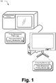
FIG. 1 is an illustration of an environment in an example implementation that is operable to perform three-dimensional printing of an object. -
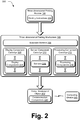
FIG. 2 is an illustration of a system in an example implementation showing a three-dimensional printing module and a three-dimensional printing mechanism ofFIG. 1 in greater detail. -
FIG. 3 depicts a system in an example implementation in which a three-dimensional object ofFIG. 2 is configured as sticky notes that are arranged on a surface. -
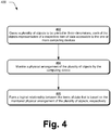
FIG. 4 is a flow diagram depicting a procedure in an example implementation in which a physical relationship of printed objects is used to define a logical relationship to items of data that are represented by the objects. -
FIG. 5 is a flow diagram depicting a procedure in an example implementation in which a user interface is output to select functionality, the functionality used as a basis to compute an arrangement and select components to be included in a three-dimensional printed object. -
FIG. 6 illustrates an example system including various components of an example device that can be implemented as any type of computing device as described with reference toFIGS. 1 and2 to implement embodiments of the techniques described herein. - Economies of scale may be leveraged to reduce cost of producing goods. However, use of these techniques may involve inefficiencies of their own, such as distribution of the goods, production of goods that go unwanted, and so forth.
- Three-dimensional printing techniques are described. In one or more implementations, a three-dimensional printer is leveraged to form objects that may be leveraged for use with a computing device. The three-dimensional printer, for instance, may be configured to form a substrate, e.g., out of a plastic or resin material. The printer may also be configured to set and interconnect components in the substrate to provide desired functionality. Examples of such components include display components (e.g., LEDs), processing components, sensor components, and so on. In this way, the three-dimensional printer may be used to form objects as desired.
- Further, in one or more additional implementations these objects may be used to extend a user's experience in interacting with a computing device. The objects, for instance, may be configured to represent items of data that are accessible to the computing device, such as documents, appointments, a to-do list, workflow, and so on. Physical arrangement of the items may then be used to define a logical arrangement of the represented items of data, such as to group the items, order the items, and so on. Further discussion of these features may be found in relation to
FIG. 3 . - In the following discussion, an example environment is first described that may employ the techniques described herein. Example procedures are then described which may be performed in the example environment as well as other environments. Consequently, performance of the example procedures is not limited to the example environment and the example environment is not limited to performance of the example procedures.
-
FIG. 1 is an illustration of anenvironment 100 in an example implementation that is operable to employ techniques described herein. The illustratedenvironment 100 includes acomputing device 102 that is communicatively coupled to a three-dimensional printer 104. Although thecomputing device 102 is illustrated as a desktop computer, thecomputing device 102 may be configured in a variety of ways, such as through a plurality of servers, distributed "via the cloud," handheld computing devices, and so on. Thus, thecomputing device 102 may be communicatively coupled to the three-dimensional printer 104 in a variety of ways, including local or remote (e.g., Internet) connections. Further, although illustrated separately the three-dimensional printer 104 may incorporate the functionality described for thecomputing device 102, e.g., to function as a stand-alone device. - The
computing device 102 is further illustrated as including a three-dimensional printing module 106. This module is representative of functionality to specify an object to be printed by the three-dimensional printer 104. The three-dimensional printing module 106, for instance, may include functionality to model an object to be formed. - The three-
dimensional printing module 106 may also be configured to output a user interface, which may be used to support a variety of different user interactions. For example, a user may specify criteria to be used to form the object by the three-dimensional printer 104, which may include a size, shape, and/or color of the object. In another example, a user may select from a variety of pre-defined objects, which may be customizable by the user, such as to a particular size of an item to be worn by the user. - According to the invention, the user interface may provide representations of functionality to be included in the object. The user interface, for instance, may include representations of functionality but not describe how that functionality is to be implemented, e.g., components that are used to implement the functionality and/or how those components are interconnected. A user, for instance, may select an option to include health sensing functionality are part of the object, such as a bracelet to be worn by the user that is usable to detect the user's heartbeat. If that option is selected, according to the invention the three-
dimension printing module 106 determines which components are to be used to implement that functionality as well as how those components are interconnected as part of the three-dimensional object. Thus, in this instance a user may select functionality to be included in the object without "figuring out" how that functionality is to be implemented. - The three-
dimensional printer 104 is illustrated as including a three-dimensional printing mechanism 108. The three-dimensional printing mechanism 108 is representative of functionality to form a three-dimensional object, which may be performed in a variety of ways. The three-dimensional printing mechanism 108, for instance, may use techniques to form the object using a plurality of layers of material, such as plastic or resins, using additive manufacturing techniques. - Examples of this include selective laser sintering (SLS) and fused deposition modeling (FDM) which use melting or softening of material to form the layers. Another example involves curing a liquid material, such as to use digital light processing (DLP) in which a liquid polymer is exposed to light from a DLP projector to form the layers. A further example involves use of inkjet printing techniques to create layers from a powder onto which a binder is printed by the three-
dimensional printing mechanism 108. A variety of other examples are also contemplated without departing from the scope thereof to form a substrate of an object. The three-dimensional printing mechanism 108 may also be configured to arrange components in the substrate to provide desired functionality, further discussion of which may be found in relation toFIG. 2 . - Generally, functions described herein can be implemented using software, firmware, hardware (e.g., fixed logic circuitry), or a combination of these implementations. The terms "module," "functionality," and "logic" as used herein generally represent software, firmware, hardware, or a combination thereof. In the case of a software implementation, the module, functionality, or logic represents program code that performs specified tasks when executed on a processor (e.g., CPU or CPUs). The program code can be stored in one or more computer readable memory devices. Thus, in this case a module and so on may be implemented at least partially in hardware. The features of the techniques described below are platform-independent, meaning that the techniques may be implemented on a variety of commercial computing platforms having a variety of processors.
- For example, the
computing device 102 may also include an entity (e.g., software) that causes hardware of thecomputing device 102 to perform operations, e.g., processors, functional blocks, and so on. For example, thecomputing device 102 may include a computer-readable medium that may be configured to maintain instructions that cause the computing device, and more particularly hardware of thecomputing device 102 to perform operations. Thus, the instructions function to configure the hardware to perform the operations and in this way result in transformation of the hardware to perform functions. The instructions may be provided by the computer-readable medium to thecomputing device 102 through a variety of different configurations. - One such configuration of a computer-readable medium is signal bearing medium and thus is configured to transmit the instructions (e.g., as a carrier wave) to the hardware of the computing device, such as via a network. The computer-readable medium may also be configured as a computer-readable storage medium and thus is not a signal bearing medium. Examples of a computer-readable storage medium include a random-access memory (RAM), read-only memory (ROM), an optical disc, flash memory, hard disk memory, and other memory devices that may use magnetic, optical, and other techniques to store instructions and other data.
-
FIG. 2 is an illustration of asystem 200 in an example implementation showing the three-dimensional printing module 106 and the three-dimensional printing mechanism 108 in greater detail. The three-dimensional printing mechanism 108 in this instance is illustrated as forming a three-dimensional object 202 based on printinginstructions 204 received from the three-dimensional printing module 106. As previously stated, the printinginstructions 204 may originate in a variety of ways, such as through interaction by a user with a user interface output by the three-dimensional printing module 106. - The three-
dimensional printing mechanism 108 may then be used to form the three-dimensional object 202 according to theprinting instructions 204. This may include forming asubstrate material 206 to have a specified size and shape, which may be performed in a variety of ways as previously described in relation toFIG. 1 . - Formation of the three-
dimensional object 202 may also include arranging one or more components in thesubstrate material 206, which may be preconfigured or formed by the three-dimensional printing mechanism 108, itself. Components may be thought of as preconfigured in that such components are not formed by the three-dimensional printing mechanism 108 itself, e.g., printed from thesubstrate material 206, a conductive ink, and so forth. On the other hand, components may also be formed by the three-dimensional printing mechanism 108 itself, such as to print electrical connections, form antennas and sensors, and so forth. - In the
system 200 ofFIG. 2 , the three-dimensional printing mechanism 108 may include a plurality of cartridges that include different types of components which may be preconfigured and/or configured for formation by theprinting mechanism 108 itself. Illustrated examples of these cartridges include adisplay component cartridge 208, asensor component cartridge 210, and aprocessing component cartridge 212 that includedisplay components 214,sensors 216, and processing components 218 respectively. Other examples are also contemplated, such as a communication component cartridge having communication components 220 that are configured to enable the three-dimensional object 202 to communicate with another object, acomputing device 222, and so on. - A variety of
different display components 214 may be included within thedisplay component cartridge 208, such as light emitting diodes (LEDs), light emitting inks, and so on. Likewise, a variety ofdifferent sensors 216 may be included within thesensor component cartridge 210 for use in forming the three-dimensional object 202. Examples ofsensors 216 include biometric sensors, such as sensors to detect biometric characteristics of a user of the three-dimensional object 202. Additional examples includesensors 216 that are configured to detect characteristics of the three-dimensional object 202 itself,sensors 216 that are configured to act as an input device (e.g., touch sensitive capacitive sensors that may be printed on the substrate material 206), and so on. - The
processing component cartridge 212 may include processing components 218 that are configured to perform one or more operations. Processing components 218 may include integrated circuits, functional blocks, system on a chip (SoC), floating point grid arrays, and so on. Further, the processing components 218 may include one or more computer-readable storage media that may be programmed with instructions to cause the processing components 218 to perform the operations. - In one or more implementations, the printing
instructions 204 may include instructions that are to be programmed on the processing components 218 to configure the processing components to perform desired operations. As described previously, in an example a user may select functionality to be included as part of the three-dimensional object 202. In response, the processing components 218 may be programmed to support that functionality, such as to interact with one or more other components, e.g., process signals from thesensors 216. Thus, the processing components 218 may be configured as part of a general purpose token that may be configured for specific operations by the three-dimensional printing mechanism 108 as part of the formation of the three-dimensional object 202. Thus, the general purpose token may be used to support a variety of functionality for implementation by a variety of different devices formed by the three-dimensional printer 104. - Accordingly, the three-
dimensional object 202 may be configured in a variety of different ways to provide a variety of different functionality. This may include functionality for medical uses (e.g., identification, medical sensors), mechanical uses, made to be wearable by a user, work as an output device, and so forth. - For example, the three-
dimensional object 202 may be configured to expand interactions involved in a user experience between a user and acomputing device 222. As illustrated, the three-dimensional object 202 may include communication components 220 that support communication with acomputing device 222. The communication components 220 may be leveraged to support a variety of functionality, e.g., the three-dimensional object 202 may include one or more sensors and communicate signals obtained from those sensors for processing by thecomputing device 222. - The three-
dimensional object 202 may also be configured as a physical representation of an item of data that is accessible by thecomputing device 222, such as an item of data stored on thecomputing device 222, available via a network connection, and so on. The three-dimensional object 202, for instance, may be configured as electronic paper such that a single "page" may be utilized to view a plurality of pages. Accordingly, a user may make changes using the object and cause those changes to be communicated back tocomputing device 222. A variety of other examples are also contemplated, such as to define a logical relationship between items of data based on a physical relationship of objects, an example of which is described in relation to the following figure. -
FIG. 3 depicts asystem 300 in an example implementation in which the three-dimensional object 202 ofFIG. 2 is configured assticky notes surface 312. The sticky notes 302-310 may be formed to include a variety of features. For example, the sticky notes 302-310 may be formed with one or more sensors that are configured to detect writing on a surface of the note. In another example, the "writing" may be formed by the three-dimensional printer 104 itself, such as to identify a respective item of data that is represented by the note. - The sticky notes 302-310 may also be configured to include functionality that may be used to determine a physical arrangement of the notes in relation to each other. This functionality may include a RFID tag that is readable by a
computing device 222, sensors for communication between the objects themselves (e.g., contact sensors, proximity sensors), and so forth. Thus, these sensors may be used to define the physical arrangement of the devices, one to another. - This physical arrangement of the objects may then be used to define a corresponding logical relationship of the items of data that are represented by the objects. In the illustrated example, the sticky notes 302-310 are representative of appointments, which in this case are steps in a product design process. The overall arrangement of the sticky notes 302-310, one to another, may be used to define an order of the appointments. Further, location on the
surface 312 may also be used to indicate timing, such as particular days in this example. This physical arrangement of the sticky notes 302-310 may thus be used to define a logical relationship of the items of data represented by the objects, e.g., the appointments. A variety of other examples are also contemplated. - For instance, objects (e.g., sticky notes 304-308) may be stacked to form a group. Thus, the group may be formed logically to include items of data represented by the notes, e.g., that design specs include a display and case. Similar techniques may be used to separate items, such as to separate stacked items into individual groups. In this way, the physical objects may be used to extend a user's experience with a
computing device 222. Although sticky notes were described, the three-dimensional object 202 may be representative of a wide variety of different types of data, such as a document, pages of a document, image, song, multimedia, appointments, items in a To-Do list, variables in a formula, contacts, tasks, notes, and so forth. - The following discussion describes three-dimensional printing techniques that may be implemented utilizing the previously described systems and devices. Aspects of each of the procedures may be implemented in hardware, firmware, or software, or a combination thereof. The procedures are shown as a set of blocks that specify operations performed by one or more devices and are not necessarily limited to the orders shown for performing the operations by the respective blocks. In portions of the following discussion, reference will be made to the
environment 100 ofFIG. 1 and thesystems FIGS. 2 and3 , respectively. -
FIG. 4 depicts aprocedure 400 in an example implementation in which a physical relationship of printed objects is used to define a logical relationship to items of data that are represented by the objects. A plurality of objects are caused to be printed in three-dimensions by a computing device, each of the objects representative of a respective item of data accessible to the one or more computing devices (block 402). As previously described, the three-dimensional object 202 may be printed in a variety of ways by the three-dimensional printing mechanism 108 of the three-dimensional printer 104. Further, these items may be representative of a variety of different items of data, such as notes, a document, pages of a document, image, song, multimedia, appointments, items in a To-Do list, variables in a formula, contacts, tasks, notes, and so forth. - A physical arrangement of the plurality of objects is monitored by the computing device (block 404). This arrangement may be monitored by the objects themselves (e.g., proximity or contact sensors), by a
computing device 222 that is communicatively coupled to the objects via one or more communication components 220, and so forth. - A logical relationship is formed between the items of data that is based on the monitored physical arrangement of the plurality of objects, respectively, by the computing device (block 406). This may include formation of groups, ordering, temporal relationships that are formed based on tracked movement of the objects (e.g., to compose an animation, mimic a manufacturing process, etc.), separation of items from a group, and so on. Thus, the objects may extend a computing experience through a physical representation of items of data. Other examples are also contemplated, such as to modify the objects and have similar modifications made to the respective items of data.
-
FIG. 5 depicts aprocedure 500 in an example implementation in which a user interface is output to select functionality, the functionality used as a basis to compute an arrangement and select components to be included in a three-dimensional printed object. A user interface is output having representations of functionality that is selectable for inclusion in an object to be formed by a three-dimensional printer, the representations not including indications of components that are to be included as part of the object to provide the functionality (block 502). The functionality, for example, may refer to operations that are to be performed by the object, such as medical operations (e.g., monitor heartbeat or temperature), provide authentication (e.g., provide a key in response to a query to access a premises, vehicle, or computing device), display techniques (e.g., change color to notify a user of a sensed condition), and so forth. - Responsive to selection of a plurality of the representations of functionality, an arrangement of the corresponding components is computed as part of the object to provide the functionality (block 504). The three-
dimensional printing module 106, for instance, may determine which components are to be formed (e.g., printed) by the three-dimensional printing mechanism 108 as well as preconfigured components that are to be included in the object. The mechanism may then compute an arrangement for the components to be included as part of the object. - This may be performed in conjunction with a variety of other inputs. For example, a camera (e.g., depth sensing camera) or other sensors may be used to detect physical characteristics of an intended user of the object. Thus, the object may also be customized for a particular user. A variety of other examples are also contemplated.
- Instructions are output describing a result of the computing by the computing device to a three-dimensional printer to cause the three-dimensional printer to form the object (block 506). The
printing instruction 204, for instance, may describe how to form a substrate and components (e.g., sensors, antennas, interconnection) of the object, where to place preconfigured components, and so forth. A variety of other examples are also contemplated. -
FIG. 6 illustrates an example system generally at 600 that includes anexample computing device 602 that is representative of one or more computing systems and/or devices that may implement the various techniques described herein. Thecomputing device 602 may be, for example, a server of a service provider, a device associated with a client (e.g., a client device), an on-chip system, and/or any other suitable computing device or computing system. Thus, thecomputing device 602 may correspond to thecomputing devices dimensional object 202 may be formed for communicative coupling to thecomputing device 602, such as a peripheral device (e.g., stylus), inclusion of one or more sensors, and so forth. - The
example computing device 602 as illustrated includes aprocessing system 604, one or more computer-readable media 606, and one or more I/O interface 608 that are communicatively coupled, one to another. Although not shown, thecomputing device 602 may further include a system bus or other data and command transfer system that couples the various components, one to another. A system bus can include any one or combination of different bus structures, such as a memory bus or memory controller, a peripheral bus, a universal serial bus, and/or a processor or local bus that utilizes any of a variety of bus architectures. A variety of other examples are also contemplated, such as control and data lines. - The
processing system 604 is representative of functionality to perform one or more operations using hardware. Accordingly, theprocessing system 604 is illustrated as includinghardware element 610 that may be configured as processors, functional blocks, and so forth. This may include implementation in hardware as an application specific integrated circuit or other logic device formed using one or more semiconductors. Thehardware elements 610 are not limited by the materials from which they are formed or the processing mechanisms employed therein. For example, processors may be comprised of semiconductor(s) and/or transistors (e.g., electronic integrated circuits (ICs)). In such a context, processor-executable instructions may be electronically-executable instructions. - The computer-
readable storage media 606 is illustrated as including memory/storage 612. The memory/storage 612 represents memory/storage capacity associated with one or more computer-readable media. The memory/storage component 612 may include volatile media (such as random access memory (RAM)) and/or nonvolatile media (such as read only memory (ROM), Flash memory, optical disks, magnetic disks, and so forth). The memory/storage component 612 may include fixed media (e.g., RAM, ROM, a fixed hard drive, and so on) as well as removable media (e.g., Flash memory, a removable hard drive, an optical disc, and so forth). The computer-readable media 606 may be configured in a variety of other ways as further described below. - Input/output interface(s) 608 are representative of functionality to allow a user to enter commands and information to
computing device 602, and also allow information to be presented to the user and/or other components or devices using various input/output devices. Examples of input devices include a keyboard, a cursor control device (e.g., a mouse), a microphone, a scanner, touch functionality (e.g., capacitive or other sensors that are configured to detect physical touch), a camera (e.g., which may employ visible or non-visible wavelengths such as infrared frequencies to recognize movement as gestures that do not involve touch), and so forth. Examples of output devices include a display device (e.g., a monitor or projector), speakers, a printer, a network card, tactile-response device, and so forth. Thus, thecomputing device 602 may be configured in a variety of ways as further described below to support user interaction. - Various techniques may be described herein in the general context of software, hardware elements, or program modules. Generally, such modules include routines, programs, objects, elements, components, data structures, and so forth that perform particular tasks or implement particular abstract data types. The terms "module," "functionality," and "component" as used herein generally represent software, firmware, hardware, or a combination thereof. The features of the techniques described herein are platform-independent, meaning that the techniques may be implemented on a variety of commercial computing platforms having a variety of processors.
- An implementation of the described modules and techniques may be stored on or transmitted across some form of computer-readable media. The computer-readable media may include a variety of media that may be accessed by the
computing device 602. By way of example, and not limitation, computer-readable media may include "computer-readable storage media" and "computer-readable signal media." - "Computer-readable storage media" may refer to media and/or devices that enable persistent and/or non-transitory storage of information in contrast to mere signal transmission, carrier waves, or signals per se. Thus, computer-readable storage media refers to non-signal bearing media. The computer-readable storage media includes hardware such as volatile and non-volatile, removable and non-removable media and/or storage devices implemented in a method or technology suitable for storage of information such as computer readable instructions, data structures, program modules, logic elements/circuits, or other data. Examples of computer-readable storage media may include, but are not limited to, RAM, ROM, EEPROM, flash memory or other memory technology, CD-ROM, digital versatile disks (DVD) or other optical storage, hard disks, magnetic cassettes, magnetic tape, magnetic disk storage or other magnetic storage devices, or other storage device, tangible media, or article of manufacture suitable to store the desired information and which may be accessed by a computer.
- "Computer-readable signal media" may refer to a signal-bearing medium that is configured to transmit instructions to the hardware of the
computing device 602, such as via a network. Signal media typically may embody computer readable instructions, data structures, program modules, or other data in a modulated data signal, such as carrier waves, data signals, or other transport mechanism. Signal media also include any information delivery media. The term "modulated data signal" means a signal that has one or more of its characteristics set or changed in such a manner as to encode information in the signal. By way of example, and not limitation, communication media include wired media such as a wired network or direct-wired connection, and wireless media such as acoustic, RF, infrared, and other wireless media. - As previously described,
hardware elements 610 and computer-readable media 606 are representative of modules, programmable device logic and/or fixed device logic implemented in a hardware form that may be employed in some embodiments to implement at least some aspects of the techniques described herein, such as to perform one or more instructions. Hardware may include components of an integrated circuit or on-chip system, an application-specific integrated circuit (ASIC), a field-programmable gate array (FPGA), a complex programmable logic device (CPLD), and other implementations in silicon or other hardware. In this context, hardware may operate as a processing device that performs program tasks defined by instructions and/or logic embodied by the hardware as well as a hardware utilized to store instructions for execution, e.g., the computer-readable storage media described previously. - Combinations of the foregoing may also be employed to implement various techniques described herein. Accordingly, software, hardware, or executable modules may be implemented as one or more instructions and/or logic embodied on some form of computer-readable storage media and/or by one or
more hardware elements 610. Thecomputing device 602 may be configured to implement particular instructions and/or functions corresponding to the software and/or hardware modules. Accordingly, implementation of a module that is executable by thecomputing device 602 as software may be achieved at least partially in hardware, e.g., through use of computer-readable storage media and/orhardware elements 610 of theprocessing system 604. The instructions and/or functions may be executable/operable by one or more articles of manufacture (for example, one ormore computing devices 602 and/or processing systems 604) to implement techniques, modules, and examples described herein. - As further illustrated in
FIG. 6 , theexample system 600 enables ubiquitous environments for a seamless user experience when running applications on a personal computer (PC), a television device, and/or a mobile device. Services and applications run substantially similar in all three environments for a common user experience when transitioning from one device to the next while utilizing an application, playing a video game, watching a video, and so on. - In the
example system 600, multiple devices are interconnected through a central computing device. The central computing device may be local to the multiple devices or may be located remotely from the multiple devices. In one embodiment, the central computing device may be a cloud of one or more server computers that are connected to the multiple devices through a network, the Internet, or other data communication link. - In one embodiment, this interconnection architecture enables functionality to be delivered across multiple devices to provide a common and seamless experience to a user of the multiple devices. Each of the multiple devices may have different physical requirements and capabilities, and the central computing device uses a platform to enable the delivery of an experience to the device that is both tailored to the device and yet common to all devices. In one embodiment, a class of target devices is created and experiences are tailored to the generic class of devices. A class of devices may be defined by physical features, types of usage, or other common characteristics of the devices.
- In various implementations, the
computing device 602 may assume a variety of different configurations, such as forcomputer 614, mobile 616, andtelevision 618 uses. Each of these configurations includes devices that may have generally different constructs and capabilities, and thus thecomputing device 602 may be configured according to one or more of the different device classes. For instance, thecomputing device 602 may be implemented as thecomputer 614 class of a device that includes a personal computer, desktop computer, a multi-screen computer, laptop computer, netbook, and so on. - The
computing device 602 may also be implemented as the mobile 616 class of device that includes mobile devices, such as a mobile phone, portable music player, portable gaming device, a tablet computer, a multi-screen computer, and so on. Thecomputing device 602 may also be implemented as thetelevision 618 class of device that includes devices having or connected to generally larger screens in casual viewing environments. These devices include televisions, set-top boxes, gaming consoles, and so on. - The techniques described herein may be supported by these various configurations of the
computing device 602 and are not limited to the specific examples of the techniques described herein. This functionality may also be implemented all or in part through use of a distributed system, such as over a "cloud" 620 via aplatform 622 as described below. - The
cloud 620 includes and/or is representative of aplatform 622 forresources 624. Theplatform 622 abstracts underlying functionality of hardware (e.g., servers) and software resources of thecloud 620. Theresources 624 may include applications and/or data that can be utilized while computer processing is executed on servers that are remote from thecomputing device 602.Resources 624 can also include services provided over the Internet and/or through a subscriber network, such as a cellular or Wi-Fi network. - The
platform 622 may abstract resources and functions to connect thecomputing device 602 with other computing devices. Theplatform 622 may also serve to abstract scaling of resources to provide a corresponding level of scale to encountered demand for theresources 624 that are implemented via theplatform 622. Accordingly, in an interconnected device embodiment, implementation of functionality described herein may be distributed throughout thesystem 600. For example, the functionality may be implemented in part on thecomputing device 602 as well as via theplatform 622 that abstracts the functionality of thecloud 620.
Claims (8)
- A system comprising:a three-dimensional printer (104) having a three-dimensional printing mechanism (108) that is configured to form a physical object (202) in three dimensions; anda first computing device (102) communicatively coupled to the three-dimensional printer,the first computing device including a three-dimensional printing module (106) implemented at least partially in hardware to cause the three-dimensional printer to form the physical object in three dimensions as having functionality configured to communicate with a second computing device (222),characterized in thatthe three-dimensional printing module is configured to:output a user interface having a plurality of different options for predefined functionality that is includable in the object that is formable by the three-dimensional printer;determine which components are to be included in the object to provide selected said functionality; andcompute an arrangement of the components for inclusion as part of the object.
- A system as described in claim 1, wherein the three-dimensional printing mechanism (108) is configured to place the components as preconfigured components within the object as part of forming the object.
- A system as described in claim 2, wherein the preconfigured component is a processing system and the three-dimensional printing module (106) is configured to program the processing system to perform one or more operations.
- A system as described in claim 3, wherein the processing system of the object is configured to communicate a result of performance of the one or more operations to the second computing device (222) for further processing by the second computing device.
- A system as described in claim 4, wherein the processing system is programming to process signals received from one or more other preconfigured components of the object that are configured as sensors.
- A system as described in claim 1, wherein the three-dimensional printer includes a plurality of cartridges, each pertaining to a different type of component.
- A system as described in claim 6, wherein the types include display components, sensor components, or processing components.
- A system as described in claim 6, wherein the three-dimensional printing mechanism is configured to communicatively couple a plurality of components as preconfigured components, one to another, as part of the forming of the object.
Applications Claiming Priority (2)
| Application Number | Priority Date | Filing Date | Title |
|---|---|---|---|
| US13/401,227 US8665479B2 (en) | 2012-02-21 | 2012-02-21 | Three-dimensional printing |
| PCT/US2013/025480 WO2013126223A1 (en) | 2012-02-21 | 2013-02-11 | Three-dimensional printing |
Publications (3)
| Publication Number | Publication Date |
|---|---|
| EP2817709A1 EP2817709A1 (en) | 2014-12-31 |
| EP2817709A4 EP2817709A4 (en) | 2015-10-28 |
| EP2817709B1 true EP2817709B1 (en) | 2017-05-03 |
Family
ID=48982071
Family Applications (1)
| Application Number | Title | Priority Date | Filing Date |
|---|---|---|---|
| EP13752184.5A Active EP2817709B1 (en) | 2012-02-21 | 2013-02-11 | Three-dimensional printing |
Country Status (7)
| Country | Link |
|---|---|
| US (1) | US8665479B2 (en) |
| EP (1) | EP2817709B1 (en) |
| JP (1) | JP6206927B2 (en) |
| KR (1) | KR102055465B1 (en) |
| CN (1) | CN104137047B (en) |
| ES (1) | ES2635238T3 (en) |
| WO (1) | WO2013126223A1 (en) |
Families Citing this family (27)
| Publication number | Priority date | Publication date | Assignee | Title |
|---|---|---|---|---|
| KR20150023971A (en) * | 2013-08-23 | 2015-03-06 | 김현재 | System for selling merchandise related to 3D printer |
| US10611098B2 (en) | 2014-01-17 | 2020-04-07 | G6 Materials Corp. | Fused filament fabrication using multi-segment filament |
| KR101641252B1 (en) * | 2014-04-08 | 2016-07-29 | 엘지전자 주식회사 | Control device for 3d printer |
| KR102223280B1 (en) * | 2014-07-16 | 2021-03-05 | 엘지전자 주식회사 | Mobile terminal |
| KR102223281B1 (en) * | 2014-07-23 | 2021-03-05 | 엘지전자 주식회사 | Mobile terminal and method for controlling the same |
| US10727537B2 (en) | 2014-09-02 | 2020-07-28 | G6 Materials Corp. | Electrochemical devices comprising nanoscopic carbon materials made by additive manufacturing |
| TWI531486B (en) | 2014-10-01 | 2016-05-01 | 國立臺灣科技大學 | Colored three-dimensional printing apparatus and colored three-dimensional printing method |
| BR112017008412A2 (en) * | 2014-10-23 | 2017-12-19 | Facebook Inc | Methods for Generating 3D Printed Substrates for Modularly Assembled Electronics |
| WO2016085474A1 (en) | 2014-11-25 | 2016-06-02 | Hewlett Packard Enterprise Development Lp | Distress signal device |
| JP6163702B2 (en) * | 2014-12-09 | 2017-07-19 | インテル・コーポレーション | Method for manufacturing package substrate or device |
| KR20160082215A (en) * | 2014-12-31 | 2016-07-08 | 주식회사 후본 | Output system for using 3 dimentional printer and the method |
| EP3242575A1 (en) * | 2015-01-06 | 2017-11-15 | Koninklijke Philips N.V. | A system and method for making a template |
| CA2978556C (en) | 2015-03-02 | 2022-02-15 | Graphene 3D Lab Inc. | Thermoplastic composites comprising water-soluble peo graft polymers useful for 3-dimensional additive manufacturing |
| US20160284122A1 (en) * | 2015-03-26 | 2016-09-29 | Intel Corporation | 3d model recognition apparatus and method |
| KR20160132283A (en) | 2015-05-08 | 2016-11-17 | 조선대학교산학협력단 | Method for minimizing the bending phenomenon of 3D printing |
| CA2993799C (en) | 2015-07-29 | 2023-10-03 | Graphene 3D Lab Inc. | Thermoplastic polymer composites and methods for preparing, collecting, and tempering 3d printable materials and articles from same |
| GB2542397B (en) | 2015-09-18 | 2019-09-25 | Reckitt Benckiser Brands Ltd | Spraying device and method of using same |
| JP6932479B2 (en) * | 2015-11-18 | 2021-09-08 | キヤノン株式会社 | Information processing terminal, management system, control method, program |
| US10259081B2 (en) | 2016-02-08 | 2019-04-16 | Board Of Regents, The University Of Texas System | Connecting metal foils/wires and components in 3D printed substrates with wire bonding |
| US10569464B2 (en) | 2016-02-08 | 2020-02-25 | Board Of Regents, The University Of Texas System | Connecting metal foils/wires at different layers in 3D printed substrates with wire spanning |
| CN106126130A (en) * | 2016-06-21 | 2016-11-16 | 重庆市光学机械研究所 | A kind of controllable visualization online 3D print system |
| WO2018057784A1 (en) * | 2016-09-22 | 2018-03-29 | University Of South Alabama | Method and apparatus for 3d printing |
| WO2018151706A1 (en) * | 2017-02-14 | 2018-08-23 | Hewlett-Packard Development Company, L.P. | 3d printed object with embedded sensing device |
| US10234848B2 (en) | 2017-05-24 | 2019-03-19 | Relativity Space, Inc. | Real-time adaptive control of additive manufacturing processes using machine learning |
| US11548228B2 (en) * | 2018-06-11 | 2023-01-10 | Hewlett-Packard Development Company, L.P. | Soft-proof of three-dimensional (3D) printed parts |
| CN109874091B (en) * | 2019-01-31 | 2021-05-18 | 歌尔股份有限公司 | Preparation method of sound absorbing piece, sound absorbing piece and loudspeaker module |
| WO2020209873A1 (en) * | 2019-04-12 | 2020-10-15 | Hewlett-Packard Development Company, L.P. | Accelerometer-based object pose determination |
Family Cites Families (16)
| Publication number | Priority date | Publication date | Assignee | Title |
|---|---|---|---|---|
| US5173220A (en) | 1991-04-26 | 1992-12-22 | Motorola, Inc. | Method of manufacturing a three-dimensional plastic article |
| JP2001001409A (en) * | 1999-06-17 | 2001-01-09 | Yaskawa Electric Corp | Manufacture of actuator by stereo lithography |
| JP2002251209A (en) * | 2001-02-23 | 2002-09-06 | Minolta Co Ltd | Data processor, data processing method, recording medium and its program |
| US20030151167A1 (en) | 2002-01-03 | 2003-08-14 | Kritchman Eliahu M. | Device, system and method for accurate printing of three dimensional objects |
| AU2003279508A1 (en) * | 2002-11-12 | 2004-06-03 | Objet Geometries Ltd. | Three-dimensional object printing |
| US7729506B2 (en) * | 2004-05-06 | 2010-06-01 | Keith Carlson | Apparatus and method for creating three dimensional relief tiles |
| US7824001B2 (en) * | 2004-09-21 | 2010-11-02 | Z Corporation | Apparatus and methods for servicing 3D printers |
| EP1898326A4 (en) | 2005-06-24 | 2009-07-29 | Fujitsu Ltd | Device design support method, program, and system |
| US8858856B2 (en) * | 2008-01-08 | 2014-10-14 | Stratasys, Inc. | Method for building and using three-dimensional objects containing embedded identification-tag inserts |
| JP5286352B2 (en) * | 2008-03-28 | 2013-09-11 | テルモ株式会社 | Biological tissue solid model and manufacturing method thereof |
| US8243334B2 (en) | 2008-06-06 | 2012-08-14 | Virginia Venture Industries, Llc | Methods and apparatuses for printing three dimensional images |
| GB201003065D0 (en) | 2010-02-23 | 2010-04-07 | Simpleware Ltd | Image processing method and method of three-dimensional printing incorporating the same |
| US20110222081A1 (en) | 2010-03-15 | 2011-09-15 | Chen Yi | Printing Three-Dimensional Objects Using Hybrid Format Data |
| US9156204B2 (en) | 2010-05-17 | 2015-10-13 | Synerdyne Corporation | Hybrid scanner fabricator |
| DE102011109368A1 (en) * | 2011-08-04 | 2013-02-07 | Arburg Gmbh + Co Kg | Process for producing a three-dimensional article of solidifiable material and article produced therewith |
| JP5408207B2 (en) * | 2011-08-25 | 2014-02-05 | コニカミノルタ株式会社 | Solid object shaping apparatus and control program |
-
2012
- 2012-02-21 US US13/401,227 patent/US8665479B2/en active Active
-
2013
- 2013-02-11 EP EP13752184.5A patent/EP2817709B1/en active Active
- 2013-02-11 WO PCT/US2013/025480 patent/WO2013126223A1/en active Application Filing
- 2013-02-11 JP JP2014557700A patent/JP6206927B2/en active Active
- 2013-02-11 KR KR1020147023208A patent/KR102055465B1/en active IP Right Grant
- 2013-02-11 CN CN201380010340.6A patent/CN104137047B/en active Active
- 2013-02-11 ES ES13752184.5T patent/ES2635238T3/en active Active
Also Published As
| Publication number | Publication date |
|---|---|
| EP2817709A4 (en) | 2015-10-28 |
| CN104137047B (en) | 2017-03-08 |
| US8665479B2 (en) | 2014-03-04 |
| JP2015508720A (en) | 2015-03-23 |
| WO2013126223A1 (en) | 2013-08-29 |
| KR102055465B1 (en) | 2019-12-12 |
| ES2635238T3 (en) | 2017-10-03 |
| KR20140130133A (en) | 2014-11-07 |
| CN104137047A (en) | 2014-11-05 |
| EP2817709A1 (en) | 2014-12-31 |
| US20130215454A1 (en) | 2013-08-22 |
| JP6206927B2 (en) | 2017-10-04 |
Similar Documents
| Publication | Publication Date | Title |
|---|---|---|
| EP2817709B1 (en) | Three-dimensional printing | |
| US10906247B2 (en) | Method and system for generating and printing three dimensional barcodes | |
| CN107580695A (en) | Embroidery formula sensor suite | |
| CN104203547B (en) | Networking 3 D-printing | |
| Okwudire et al. | Distributed manufacturing for and by the masses | |
| US10775769B2 (en) | Information processing apparatus, control method, and storage medium | |
| US8792142B2 (en) | Methods and systems for creating structural documents having contact information for utilizing product information | |
| CN106796480A (en) | Many finger touch pad gestures | |
| US10576688B2 (en) | Management system and control method of 3D printer | |
| CN105518566A (en) | Display rotation management | |
| CN103677806B (en) | Method and system for system administration | |
| US20210073871A1 (en) | Search Result-Based Listing Generation In A Single View | |
| CN107436694A (en) | Force snesor with the uniform response along axle | |
| Song et al. | Performance analysis of CyberManufacturing systems | |
| Ward et al. | Real-time vision-based multiple object tracking of a production process: Industrial digital twin case study | |
| CN104106040A (en) | Visual representation of chart scaling | |
| Paul et al. | Manufacturing of smart goods: Current state, future potential, and research recommendations | |
| JP2018034441A (en) | Information processor, control method, and program | |
| CN107844645B (en) | BIM-based collaboration initiating method and device | |
| CN104462631B (en) | Circuit diagram generating device and circuit diagram generating method | |
| CN109712221A (en) | Three-dimensional visualization rendering method and device | |
| US11687708B2 (en) | Generator for synthesizing templates | |
| WO2020166389A1 (en) | Method for collecting and using ideas pertaining to product | |
| US10354101B1 (en) | System for providing an alternative control interface to specialty devices | |
| US9058143B1 (en) | System for providing an alternative control interface to specialty printing devices |
Legal Events
| Date | Code | Title | Description |
|---|---|---|---|
| PUAI | Public reference made under article 153(3) epc to a published international application that has entered the european phase |
Free format text: ORIGINAL CODE: 0009012 |
|
| 17P | Request for examination filed |
Effective date: 20140811 |
|
| AK | Designated contracting states |
Kind code of ref document: A1 Designated state(s): AL AT BE BG CH CY CZ DE DK EE ES FI FR GB GR HR HU IE IS IT LI LT LU LV MC MK MT NL NO PL PT RO RS SE SI SK SM TR |
|
| AX | Request for extension of the european patent |
Extension state: BA ME |
|
| RAP1 | Party data changed (applicant data changed or rights of an application transferred) |
Owner name: MICROSOFT TECHNOLOGY LICENSING, LLC |
|
| DAX | Request for extension of the european patent (deleted) | ||
| RA4 | Supplementary search report drawn up and despatched (corrected) |
Effective date: 20150925 |
|
| RIC1 | Information provided on ipc code assigned before grant |
Ipc: G06F 3/12 20060101AFI20150921BHEP Ipc: B29C 67/00 20060101ALI20150921BHEP |
|
| GRAP | Despatch of communication of intention to grant a patent |
Free format text: ORIGINAL CODE: EPIDOSNIGR1 |
|
| INTG | Intention to grant announced |
Effective date: 20161130 |
|
| GRAS | Grant fee paid |
Free format text: ORIGINAL CODE: EPIDOSNIGR3 |
|
| GRAA | (expected) grant |
Free format text: ORIGINAL CODE: 0009210 |
|
| AK | Designated contracting states |
Kind code of ref document: B1 Designated state(s): AL AT BE BG CH CY CZ DE DK EE ES FI FR GB GR HR HU IE IS IT LI LT LU LV MC MK MT NL NO PL PT RO RS SE SI SK SM TR |
|
| REG | Reference to a national code |
Ref country code: GB Ref legal event code: FG4D |
|
| REG | Reference to a national code |
Ref country code: AT Ref legal event code: REF Ref document number: 890685 Country of ref document: AT Kind code of ref document: T Effective date: 20170515 Ref country code: CH Ref legal event code: EP |
|
| REG | Reference to a national code |
Ref country code: IE Ref legal event code: FG4D |
|
| REG | Reference to a national code |
Ref country code: DE Ref legal event code: R096 Ref document number: 602013020644 Country of ref document: DE |
|
| REG | Reference to a national code |
Ref country code: NL Ref legal event code: FP |
|
| REG | Reference to a national code |
Ref country code: AT Ref legal event code: MK05 Ref document number: 890685 Country of ref document: AT Kind code of ref document: T Effective date: 20170503 |
|
| REG | Reference to a national code |
Ref country code: LT Ref legal event code: MG4D |
|
| REG | Reference to a national code |
Ref country code: ES Ref legal event code: FG2A Ref document number: 2635238 Country of ref document: ES Kind code of ref document: T3 Effective date: 20171003 |
|
| PG25 | Lapsed in a contracting state [announced via postgrant information from national office to epo] |
Ref country code: HR Free format text: LAPSE BECAUSE OF FAILURE TO SUBMIT A TRANSLATION OF THE DESCRIPTION OR TO PAY THE FEE WITHIN THE PRESCRIBED TIME-LIMIT Effective date: 20170503 Ref country code: GR Free format text: LAPSE BECAUSE OF FAILURE TO SUBMIT A TRANSLATION OF THE DESCRIPTION OR TO PAY THE FEE WITHIN THE PRESCRIBED TIME-LIMIT Effective date: 20170804 Ref country code: AT Free format text: LAPSE BECAUSE OF FAILURE TO SUBMIT A TRANSLATION OF THE DESCRIPTION OR TO PAY THE FEE WITHIN THE PRESCRIBED TIME-LIMIT Effective date: 20170503 Ref country code: LT Free format text: LAPSE BECAUSE OF FAILURE TO SUBMIT A TRANSLATION OF THE DESCRIPTION OR TO PAY THE FEE WITHIN THE PRESCRIBED TIME-LIMIT Effective date: 20170503 Ref country code: FI Free format text: LAPSE BECAUSE OF FAILURE TO SUBMIT A TRANSLATION OF THE DESCRIPTION OR TO PAY THE FEE WITHIN THE PRESCRIBED TIME-LIMIT Effective date: 20170503 Ref country code: NO Free format text: LAPSE BECAUSE OF FAILURE TO SUBMIT A TRANSLATION OF THE DESCRIPTION OR TO PAY THE FEE WITHIN THE PRESCRIBED TIME-LIMIT Effective date: 20170803 |
|
| PG25 | Lapsed in a contracting state [announced via postgrant information from national office to epo] |
Ref country code: BG Free format text: LAPSE BECAUSE OF FAILURE TO SUBMIT A TRANSLATION OF THE DESCRIPTION OR TO PAY THE FEE WITHIN THE PRESCRIBED TIME-LIMIT Effective date: 20170803 Ref country code: SE Free format text: LAPSE BECAUSE OF FAILURE TO SUBMIT A TRANSLATION OF THE DESCRIPTION OR TO PAY THE FEE WITHIN THE PRESCRIBED TIME-LIMIT Effective date: 20170503 Ref country code: PL Free format text: LAPSE BECAUSE OF FAILURE TO SUBMIT A TRANSLATION OF THE DESCRIPTION OR TO PAY THE FEE WITHIN THE PRESCRIBED TIME-LIMIT Effective date: 20170503 Ref country code: IS Free format text: LAPSE BECAUSE OF FAILURE TO SUBMIT A TRANSLATION OF THE DESCRIPTION OR TO PAY THE FEE WITHIN THE PRESCRIBED TIME-LIMIT Effective date: 20170903 Ref country code: RS Free format text: LAPSE BECAUSE OF FAILURE TO SUBMIT A TRANSLATION OF THE DESCRIPTION OR TO PAY THE FEE WITHIN THE PRESCRIBED TIME-LIMIT Effective date: 20170503 Ref country code: LV Free format text: LAPSE BECAUSE OF FAILURE TO SUBMIT A TRANSLATION OF THE DESCRIPTION OR TO PAY THE FEE WITHIN THE PRESCRIBED TIME-LIMIT Effective date: 20170503 |
|
| REG | Reference to a national code |
Ref country code: FR Ref legal event code: PLFP Year of fee payment: 6 |
|
| PG25 | Lapsed in a contracting state [announced via postgrant information from national office to epo] |
Ref country code: RO Free format text: LAPSE BECAUSE OF FAILURE TO SUBMIT A TRANSLATION OF THE DESCRIPTION OR TO PAY THE FEE WITHIN THE PRESCRIBED TIME-LIMIT Effective date: 20170503 Ref country code: SK Free format text: LAPSE BECAUSE OF FAILURE TO SUBMIT A TRANSLATION OF THE DESCRIPTION OR TO PAY THE FEE WITHIN THE PRESCRIBED TIME-LIMIT Effective date: 20170503 Ref country code: DK Free format text: LAPSE BECAUSE OF FAILURE TO SUBMIT A TRANSLATION OF THE DESCRIPTION OR TO PAY THE FEE WITHIN THE PRESCRIBED TIME-LIMIT Effective date: 20170503 Ref country code: CZ Free format text: LAPSE BECAUSE OF FAILURE TO SUBMIT A TRANSLATION OF THE DESCRIPTION OR TO PAY THE FEE WITHIN THE PRESCRIBED TIME-LIMIT Effective date: 20170503 Ref country code: EE Free format text: LAPSE BECAUSE OF FAILURE TO SUBMIT A TRANSLATION OF THE DESCRIPTION OR TO PAY THE FEE WITHIN THE PRESCRIBED TIME-LIMIT Effective date: 20170503 |
|
| REG | Reference to a national code |
Ref country code: DE Ref legal event code: R097 Ref document number: 602013020644 Country of ref document: DE |
|
| PG25 | Lapsed in a contracting state [announced via postgrant information from national office to epo] |
Ref country code: SM Free format text: LAPSE BECAUSE OF FAILURE TO SUBMIT A TRANSLATION OF THE DESCRIPTION OR TO PAY THE FEE WITHIN THE PRESCRIBED TIME-LIMIT Effective date: 20170503 |
|
| PLBE | No opposition filed within time limit |
Free format text: ORIGINAL CODE: 0009261 |
|
| STAA | Information on the status of an ep patent application or granted ep patent |
Free format text: STATUS: NO OPPOSITION FILED WITHIN TIME LIMIT |
|
| 26N | No opposition filed |
Effective date: 20180206 |
|
| PG25 | Lapsed in a contracting state [announced via postgrant information from national office to epo] |
Ref country code: SI Free format text: LAPSE BECAUSE OF FAILURE TO SUBMIT A TRANSLATION OF THE DESCRIPTION OR TO PAY THE FEE WITHIN THE PRESCRIBED TIME-LIMIT Effective date: 20170503 |
|
| REG | Reference to a national code |
Ref country code: CH Ref legal event code: PL |
|
| PG25 | Lapsed in a contracting state [announced via postgrant information from national office to epo] |
Ref country code: MC Free format text: LAPSE BECAUSE OF FAILURE TO SUBMIT A TRANSLATION OF THE DESCRIPTION OR TO PAY THE FEE WITHIN THE PRESCRIBED TIME-LIMIT Effective date: 20170503 |
|
| REG | Reference to a national code |
Ref country code: IE Ref legal event code: MM4A |
|
| REG | Reference to a national code |
Ref country code: BE Ref legal event code: MM Effective date: 20180228 |
|
| PG25 | Lapsed in a contracting state [announced via postgrant information from national office to epo] |
Ref country code: LU Free format text: LAPSE BECAUSE OF NON-PAYMENT OF DUE FEES Effective date: 20180211 Ref country code: LI Free format text: LAPSE BECAUSE OF NON-PAYMENT OF DUE FEES Effective date: 20180228 Ref country code: CH Free format text: LAPSE BECAUSE OF NON-PAYMENT OF DUE FEES Effective date: 20180228 |
|
| PG25 | Lapsed in a contracting state [announced via postgrant information from national office to epo] |
Ref country code: IE Free format text: LAPSE BECAUSE OF NON-PAYMENT OF DUE FEES Effective date: 20180211 |
|
| PG25 | Lapsed in a contracting state [announced via postgrant information from national office to epo] |
Ref country code: BE Free format text: LAPSE BECAUSE OF NON-PAYMENT OF DUE FEES Effective date: 20180228 |
|
| PG25 | Lapsed in a contracting state [announced via postgrant information from national office to epo] |
Ref country code: MT Free format text: LAPSE BECAUSE OF NON-PAYMENT OF DUE FEES Effective date: 20180211 |
|
| PG25 | Lapsed in a contracting state [announced via postgrant information from national office to epo] |
Ref country code: TR Free format text: LAPSE BECAUSE OF FAILURE TO SUBMIT A TRANSLATION OF THE DESCRIPTION OR TO PAY THE FEE WITHIN THE PRESCRIBED TIME-LIMIT Effective date: 20170503 |
|
| PG25 | Lapsed in a contracting state [announced via postgrant information from national office to epo] |
Ref country code: HU Free format text: LAPSE BECAUSE OF FAILURE TO SUBMIT A TRANSLATION OF THE DESCRIPTION OR TO PAY THE FEE WITHIN THE PRESCRIBED TIME-LIMIT; INVALID AB INITIO Effective date: 20130211 Ref country code: PT Free format text: LAPSE BECAUSE OF FAILURE TO SUBMIT A TRANSLATION OF THE DESCRIPTION OR TO PAY THE FEE WITHIN THE PRESCRIBED TIME-LIMIT Effective date: 20170503 |
|
| PG25 | Lapsed in a contracting state [announced via postgrant information from national office to epo] |
Ref country code: CY Free format text: LAPSE BECAUSE OF FAILURE TO SUBMIT A TRANSLATION OF THE DESCRIPTION OR TO PAY THE FEE WITHIN THE PRESCRIBED TIME-LIMIT Effective date: 20170503 Ref country code: MK Free format text: LAPSE BECAUSE OF NON-PAYMENT OF DUE FEES Effective date: 20170503 |
|
| PG25 | Lapsed in a contracting state [announced via postgrant information from national office to epo] |
Ref country code: AL Free format text: LAPSE BECAUSE OF FAILURE TO SUBMIT A TRANSLATION OF THE DESCRIPTION OR TO PAY THE FEE WITHIN THE PRESCRIBED TIME-LIMIT Effective date: 20170503 |
|
| PGFP | Annual fee paid to national office [announced via postgrant information from national office to epo] |
Ref country code: GB Payment date: 20221230 Year of fee payment: 11 |
|
| PGFP | Annual fee paid to national office [announced via postgrant information from national office to epo] |
Ref country code: FR Payment date: 20230110 Year of fee payment: 11 Ref country code: ES Payment date: 20230314 Year of fee payment: 11 |
|
| PGFP | Annual fee paid to national office [announced via postgrant information from national office to epo] |
Ref country code: IT Payment date: 20230110 Year of fee payment: 11 Ref country code: DE Payment date: 20221230 Year of fee payment: 11 |
|
| P01 | Opt-out of the competence of the unified patent court (upc) registered |
Effective date: 20230505 |
|
| PGFP | Annual fee paid to national office [announced via postgrant information from national office to epo] |
Ref country code: NL Payment date: 20230113 Year of fee payment: 11 |
|
| PGFP | Annual fee paid to national office [announced via postgrant information from national office to epo] |
Ref country code: NL Payment date: 20240123 Year of fee payment: 12 |
|
| PGFP | Annual fee paid to national office [announced via postgrant information from national office to epo] |
Ref country code: ES Payment date: 20240301 Year of fee payment: 12 |