EP2817102B1 - Dispenser comprising actuating piston and outlet check valve - Google Patents
Dispenser comprising actuating piston and outlet check valve Download PDFInfo
- Publication number
- EP2817102B1 EP2817102B1 EP13708884.5A EP13708884A EP2817102B1 EP 2817102 B1 EP2817102 B1 EP 2817102B1 EP 13708884 A EP13708884 A EP 13708884A EP 2817102 B1 EP2817102 B1 EP 2817102B1
- Authority
- EP
- European Patent Office
- Prior art keywords
- valve
- container
- valved
- seal
- container assembly
- Prior art date
- Legal status (The legal status is an assumption and is not a legal conclusion. Google has not performed a legal analysis and makes no representation as to the accuracy of the status listed.)
- Active
Links
Images


Classifications
-
- A—HUMAN NECESSITIES
- A61—MEDICAL OR VETERINARY SCIENCE; HYGIENE
- A61M—DEVICES FOR INTRODUCING MEDIA INTO, OR ONTO, THE BODY; DEVICES FOR TRANSDUCING BODY MEDIA OR FOR TAKING MEDIA FROM THE BODY; DEVICES FOR PRODUCING OR ENDING SLEEP OR STUPOR
- A61M3/00—Medical syringes, e.g. enemata; Irrigators
- A61M3/02—Enemata; Irrigators
- A61M3/0279—Cannula; Nozzles; Tips; their connection means
-
- A—HUMAN NECESSITIES
- A61—MEDICAL OR VETERINARY SCIENCE; HYGIENE
- A61M—DEVICES FOR INTRODUCING MEDIA INTO, OR ONTO, THE BODY; DEVICES FOR TRANSDUCING BODY MEDIA OR FOR TAKING MEDIA FROM THE BODY; DEVICES FOR PRODUCING OR ENDING SLEEP OR STUPOR
- A61M15/00—Inhalators
- A61M15/0028—Inhalators using prepacked dosages, one for each application, e.g. capsules to be perforated or broken-up
- A61M15/003—Inhalators using prepacked dosages, one for each application, e.g. capsules to be perforated or broken-up using capsules, e.g. to be perforated or broken-up
-
- A—HUMAN NECESSITIES
- A61—MEDICAL OR VETERINARY SCIENCE; HYGIENE
- A61M—DEVICES FOR INTRODUCING MEDIA INTO, OR ONTO, THE BODY; DEVICES FOR TRANSDUCING BODY MEDIA OR FOR TAKING MEDIA FROM THE BODY; DEVICES FOR PRODUCING OR ENDING SLEEP OR STUPOR
- A61M15/00—Inhalators
- A61M15/08—Inhaling devices inserted into the nose
-
- A—HUMAN NECESSITIES
- A61—MEDICAL OR VETERINARY SCIENCE; HYGIENE
- A61M—DEVICES FOR INTRODUCING MEDIA INTO, OR ONTO, THE BODY; DEVICES FOR TRANSDUCING BODY MEDIA OR FOR TAKING MEDIA FROM THE BODY; DEVICES FOR PRODUCING OR ENDING SLEEP OR STUPOR
- A61M31/00—Devices for introducing or retaining media, e.g. remedies, in cavities of the body
-
- A—HUMAN NECESSITIES
- A61—MEDICAL OR VETERINARY SCIENCE; HYGIENE
- A61M—DEVICES FOR INTRODUCING MEDIA INTO, OR ONTO, THE BODY; DEVICES FOR TRANSDUCING BODY MEDIA OR FOR TAKING MEDIA FROM THE BODY; DEVICES FOR PRODUCING OR ENDING SLEEP OR STUPOR
- A61M39/00—Tubes, tube connectors, tube couplings, valves, access sites or the like, specially adapted for medical use
- A61M39/22—Valves or arrangement of valves
- A61M39/24—Check- or non-return valves
-
- B—PERFORMING OPERATIONS; TRANSPORTING
- B05—SPRAYING OR ATOMISING IN GENERAL; APPLYING FLUENT MATERIALS TO SURFACES, IN GENERAL
- B05B—SPRAYING APPARATUS; ATOMISING APPARATUS; NOZZLES
- B05B11/00—Single-unit hand-held apparatus in which flow of contents is produced by the muscular force of the operator at the moment of use
- B05B11/0005—Components or details
- B05B11/0062—Outlet valves actuated by the pressure of the fluid to be sprayed
- B05B11/007—Outlet valves actuated by the pressure of the fluid to be sprayed being opened by deformation of a sealing element made of resiliently deformable material, e.g. flaps, skirts, duck-bill valves
-
- B—PERFORMING OPERATIONS; TRANSPORTING
- B05—SPRAYING OR ATOMISING IN GENERAL; APPLYING FLUENT MATERIALS TO SURFACES, IN GENERAL
- B05B—SPRAYING APPARATUS; ATOMISING APPARATUS; NOZZLES
- B05B11/00—Single-unit hand-held apparatus in which flow of contents is produced by the muscular force of the operator at the moment of use
- B05B11/01—Single-unit hand-held apparatus in which flow of contents is produced by the muscular force of the operator at the moment of use characterised by the means producing the flow
- B05B11/02—Membranes or pistons acting on the contents inside the container, e.g. follower pistons
-
- B—PERFORMING OPERATIONS; TRANSPORTING
- B05—SPRAYING OR ATOMISING IN GENERAL; APPLYING FLUENT MATERIALS TO SURFACES, IN GENERAL
- B05B—SPRAYING APPARATUS; ATOMISING APPARATUS; NOZZLES
- B05B7/00—Spraying apparatus for discharge of liquids or other fluent materials from two or more sources, e.g. of liquid and air, of powder and gas
- B05B7/24—Spraying apparatus for discharge of liquids or other fluent materials from two or more sources, e.g. of liquid and air, of powder and gas with means, e.g. a container, for supplying liquid or other fluent material to a discharge device
-
- B—PERFORMING OPERATIONS; TRANSPORTING
- B65—CONVEYING; PACKING; STORING; HANDLING THIN OR FILAMENTARY MATERIAL
- B65D—CONTAINERS FOR STORAGE OR TRANSPORT OF ARTICLES OR MATERIALS, e.g. BAGS, BARRELS, BOTTLES, BOXES, CANS, CARTONS, CRATES, DRUMS, JARS, TANKS, HOPPERS, FORWARDING CONTAINERS; ACCESSORIES, CLOSURES, OR FITTINGS THEREFOR; PACKAGING ELEMENTS; PACKAGES
- B65D47/00—Closures with filling and discharging, or with discharging, devices
- B65D47/04—Closures with discharging devices other than pumps
- B65D47/20—Closures with discharging devices other than pumps comprising hand-operated members for controlling discharge
- B65D47/2018—Closures with discharging devices other than pumps comprising hand-operated members for controlling discharge comprising a valve or like element which is opened or closed by deformation of the container or closure
- B65D47/2025—Flexible bung-type elements
-
- B—PERFORMING OPERATIONS; TRANSPORTING
- B65—CONVEYING; PACKING; STORING; HANDLING THIN OR FILAMENTARY MATERIAL
- B65D—CONTAINERS FOR STORAGE OR TRANSPORT OF ARTICLES OR MATERIALS, e.g. BAGS, BARRELS, BOTTLES, BOXES, CANS, CARTONS, CRATES, DRUMS, JARS, TANKS, HOPPERS, FORWARDING CONTAINERS; ACCESSORIES, CLOSURES, OR FITTINGS THEREFOR; PACKAGING ELEMENTS; PACKAGES
- B65D83/00—Containers or packages with special means for dispensing contents
- B65D83/14—Containers for dispensing liquid or semi-liquid contents by internal gaseous pressure, i.e. aerosol containers comprising propellant
-
- B—PERFORMING OPERATIONS; TRANSPORTING
- B65—CONVEYING; PACKING; STORING; HANDLING THIN OR FILAMENTARY MATERIAL
- B65D—CONTAINERS FOR STORAGE OR TRANSPORT OF ARTICLES OR MATERIALS, e.g. BAGS, BARRELS, BOTTLES, BOXES, CANS, CARTONS, CRATES, DRUMS, JARS, TANKS, HOPPERS, FORWARDING CONTAINERS; ACCESSORIES, CLOSURES, OR FITTINGS THEREFOR; PACKAGING ELEMENTS; PACKAGES
- B65D83/00—Containers or packages with special means for dispensing contents
- B65D83/76—Containers or packages with special means for dispensing contents for dispensing fluent contents by means of a piston
-
- A—HUMAN NECESSITIES
- A61—MEDICAL OR VETERINARY SCIENCE; HYGIENE
- A61M—DEVICES FOR INTRODUCING MEDIA INTO, OR ONTO, THE BODY; DEVICES FOR TRANSDUCING BODY MEDIA OR FOR TAKING MEDIA FROM THE BODY; DEVICES FOR PRODUCING OR ENDING SLEEP OR STUPOR
- A61M11/00—Sprayers or atomisers specially adapted for therapeutic purposes
- A61M11/006—Sprayers or atomisers specially adapted for therapeutic purposes operated by applying mechanical pressure to the liquid to be sprayed or atomised
- A61M11/007—Syringe-type or piston-type sprayers or atomisers
-
- A—HUMAN NECESSITIES
- A61—MEDICAL OR VETERINARY SCIENCE; HYGIENE
- A61M—DEVICES FOR INTRODUCING MEDIA INTO, OR ONTO, THE BODY; DEVICES FOR TRANSDUCING BODY MEDIA OR FOR TAKING MEDIA FROM THE BODY; DEVICES FOR PRODUCING OR ENDING SLEEP OR STUPOR
- A61M15/00—Inhalators
- A61M15/0028—Inhalators using prepacked dosages, one for each application, e.g. capsules to be perforated or broken-up
- A61M15/003—Inhalators using prepacked dosages, one for each application, e.g. capsules to be perforated or broken-up using capsules, e.g. to be perforated or broken-up
- A61M15/0043—Non-destructive separation of the package, e.g. peeling
-
- A—HUMAN NECESSITIES
- A61—MEDICAL OR VETERINARY SCIENCE; HYGIENE
- A61M—DEVICES FOR INTRODUCING MEDIA INTO, OR ONTO, THE BODY; DEVICES FOR TRANSDUCING BODY MEDIA OR FOR TAKING MEDIA FROM THE BODY; DEVICES FOR PRODUCING OR ENDING SLEEP OR STUPOR
- A61M5/00—Devices for bringing media into the body in a subcutaneous, intra-vascular or intramuscular way; Accessories therefor, e.g. filling or cleaning devices, arm-rests
- A61M5/178—Syringes
- A61M5/31—Details
- A61M2005/3128—Incorporating one-way valves, e.g. pressure-relief or non-return valves
-
- A—HUMAN NECESSITIES
- A61—MEDICAL OR VETERINARY SCIENCE; HYGIENE
- A61M—DEVICES FOR INTRODUCING MEDIA INTO, OR ONTO, THE BODY; DEVICES FOR TRANSDUCING BODY MEDIA OR FOR TAKING MEDIA FROM THE BODY; DEVICES FOR PRODUCING OR ENDING SLEEP OR STUPOR
- A61M39/00—Tubes, tube connectors, tube couplings, valves, access sites or the like, specially adapted for medical use
- A61M39/22—Valves or arrangement of valves
- A61M39/24—Check- or non-return valves
- A61M2039/242—Check- or non-return valves designed to open when a predetermined pressure or flow rate has been reached, e.g. check valve actuated by fluid
-
- A—HUMAN NECESSITIES
- A61—MEDICAL OR VETERINARY SCIENCE; HYGIENE
- A61M—DEVICES FOR INTRODUCING MEDIA INTO, OR ONTO, THE BODY; DEVICES FOR TRANSDUCING BODY MEDIA OR FOR TAKING MEDIA FROM THE BODY; DEVICES FOR PRODUCING OR ENDING SLEEP OR STUPOR
- A61M2202/00—Special media to be introduced, removed or treated
- A61M2202/04—Liquids
- A61M2202/0468—Liquids non-physiological
-
- A—HUMAN NECESSITIES
- A61—MEDICAL OR VETERINARY SCIENCE; HYGIENE
- A61M—DEVICES FOR INTRODUCING MEDIA INTO, OR ONTO, THE BODY; DEVICES FOR TRANSDUCING BODY MEDIA OR FOR TAKING MEDIA FROM THE BODY; DEVICES FOR PRODUCING OR ENDING SLEEP OR STUPOR
- A61M2210/00—Anatomical parts of the body
- A61M2210/06—Head
- A61M2210/0618—Nose
Definitions
- This invention relates to a valved container assembly, and in particular to a valved container assembly having a self opening valve.
- GB2400040 (Bespak plc) describes a closure member for a container, such as a vial, that seeks to facilitate the delivery of a metered dose of medicament, for example, in a nasal dispenser.
- GB2400040 describes a container or vial for a fluid, the container comprising a casing defining an interior for storage of the fluid and a closure member.
- the closure member comprises a body and at least one resilient projection to seal in a storage condition an outlet of the casing, wherein upon an increase in the pressure of the interior of the container the at least one resilient projection is deflected to accommodate outflow of fluid through the outlet.
- the closure member has a sealing portion that seals the closure member to the container about the circumference of the closure member, and pressure in the interior of the container is increased by displacing the closure member into the container.
- the container is part of a dispensing apparatus. In this embodiment, however, the sealing portion is separate to the closure member and forms a bung that is displaceable in the interior of the container to increase the pressure therein.
- valved container assembly comprising:
- the resilient seal preferably comprises one or more flexible elements, wherein, preferably, said one or more flexible elements partly extends circumferentially around said valve and the remainder of the valve forms a seal with the container circumferentially around said one or more flexible elements.
- said one or more flexible elements extends entirely circumferentially around said valve.
- the resilient seal may comprise at least two flexible elements, wherein the at least two flexible elements may be axially aligned with one another.
- the channel preferably comprises at least one axial channel part and at least one additional channel part arranged substantially perpendicularly to said at least one axial channel and in fluid communication therewith.
- the permanent seal comprises at least one flange projecting outwardly from said valve about the entire perimeter of the valve.
- the permanent seal preferably comprises at least two flanges projecting outwardly from said valve about the entire perimeter of the valve, wherein the at least two flanges are arranged in axial alignment with one another.
- Said plunger element preferably comprises a plunger stopper and a plunger rod connected to the plunger stopper for axially moving the plunger stopper in the container.
- Said valve may comprise elastomeric material.
- Said permanent seal may comprise a weld between the valve and the container.
- said weld is a radio frequency (RF) weld.
- said weld is a heat weld.
- said permanent seal includes an adhesive join between the valve and the container.
- forward axial movement of the valve relative to the container is inhibited by one or more formations projecting radially inwardly from an interior surface of the container at an axial location that is axially forwards of the permanent seal.
- the valved container assembly may further comprise one or more formations projecting radially inwardly from an interior surface of the container at an axial location that is axially rearwards of the permanent seal.
- a nasal dispenser comprising the valved container assembly of the first aspect of the present invention.
- a method of using a valved container assembly comprising the steps of:
- FIGS 1A to 1C show the various stages of operation of a valved container assembly 10 in accordance with one embodiment of the present invention.
- the valved container assembly 10 comprises a container 12 that is preferably cylindrical, a valve 14 disposed in the container 12 and a plunger element 32 disposed in the container 12.
- the container 12 extends along a longitudinal axis between an open front end 12a and an open rear end 12b.
- references to "forward” or “front” or the like are in reference to the open front end 12a of the container 12
- references to “rearward” or “rear” or the like are in reference to the open rear end 12b of the container 12
- references to "axial” or the like are considered to denote directions parallel to the longitudinal axis of the container.
- the valve 14 is disposed in the container 12 at or near the open front end 12a and comprises a permanent seal 16 that forms a fluid tight seal with the interior of the container 12 around the entire periphery of the valve 14.
- the permanent seal 16 may be formed by a permanent fixation between the valve 14 and the container such as a radio frequency (RF) weld or heat weld, or by an alternative fixing means such as a suitable adhesive.
- RF radio frequency
- the valve 14 may be elastomeric and the permanent seal 16 may be formed by the elastomeric nature of the valve 14, with the permanent seal 16 bearing against the container 12.
- the valve 14 must be retained axially within the container 12 so that it does not move axially forwardly, and certainly does not exit the container 12 through the open front end 12a.
- the valve 14 may be prevented from moving axially forwardly relative to the container 12 so that the permanent seal 16 no longer seals between the valve 14 and the container 12.
- ribs 13 projecting radially inwardly from the interior surface of the container inhibit forward axial movement of the valve 14 relative to the container 12.
- One or more ribs 13 or alternative formations may be employed to prevent forward axial movement of the valve 14 relative to the container 12.
- the ribs 13 or alternative formations may extend partly or entirely around the inner circumference of the container 12.
- further ribs or alternative formations may be disposed axially rearward of the permanent seal 16 so as to inhibit axially rearward movement of the valve 14 relative to the container 12.
- the valve 14 has a resilient seal 22 that is formed of a pair of axially aligned flexible elements 22a,22b that extend radially from the valve 14 and extend around the entire periphery of the valve 14.
- the resilient seal 22 is moveable between a sealing configuration (as shown in figure 1A ) and an open configuration (as shown in Figure 1 B) , where in the sealing configuration, the resilient seal 22 fluidly seals the valve 14 to the container 12, and in the open configuration, the resilient seal 22 does not fluidly seal the valve 14 to the container 12.
- a first volume 24 that can contain a fluid such as a fluidic medicament.
- a channel 18 passes through the valve 14 and has a first opening 20a which vents to the atmosphere outside of the container 12 and two second openings 20b that are each selectively sealed from the first volume 24 by the resilient seal 22.
- the channel 18 has a first axial channel part 18a and a second channel part 18b arranged substantially perpendicularly to the first axial channel part 18a.
- the first opening 20a is associated with the first axial channel part 18a and the two second openings 20b are associated with the second channel part 18b.
- the channel 18 is T-shaped in cross-section.
- the resilient seal 22 When the resilient seal 22 is in the sealing configuration, the first volume 24 is fluidly sealed within the container by the valve 14. Conversely, when the resilient seal 22 is in the open configuration the first volume 24 is in fluid communication with the atmosphere via the channel 18. Thus, since the resilient seal 22 is moveable between the sealing configuration and the open configuration, so too is the valve 14 as a whole, since it selectively fluidly isolates and fluidly connects the first volume 24 to the atmosphere via the channel 18 depending on the configuration of the resilient seal 22.
- the resilient seal 22 is moved from the sealing configuration to the open configuration when a force incident on the resilient seal 22 exceeds at predetermined threshold.
- a force incident on the resilient seal 22 exceeds at predetermined threshold.
- a force incident on the resilient seal 22 exceeds at predetermined threshold.
- the fluid pressure of a fluid acting on the resilient seal 22 exceeds a predetermined threshold.
- the resilient seal 22 would move from the sealing configuration to the open configuration when the pressure of the fluid exceeded the predetermined threshold.
- the flexible elements 22a,22b of the resilient seal 22 flex or deflect so as to move away from the container 12 and open a fluid pathway allowing fluid to bypass the resilient seal 22.
- Alternative components may form the resilient seal 22 in place of the flexible elements 22a,22b that deform, deflect, flex or otherwise move to open a fluid pathway between the valve 14 and the container 12 upon application of a predetermined force.
- the flexible elements 22a,22b are shown to be flexed or deflected in a forward direction, such as one might expect to result from the pressure of a fluid in the first volume exceeding the predetermined pressure threshold.
- the permanent seal 16 remains in place and maintains a seal between the valve 14 and the container 12 axially forwards of the resilient seal 22.
- a fluid connection is only formed between the first volume 24 and the atmosphere when the resilient seal 22 is in the open configuration.
- fluid must flow along several axes in order to bypass the permanent seal 16 through the channel 18.
- This arrangement therefore provides a labyrinth pathway between the first volume 24 and the atmosphere, as opposed to a straight channel.
- a benefit of the labyrinth arrangement is that the likelihood of fluid flow from the first volume to the atmosphere is substantially reduced in the event that the resilient seal 22 is inadvertently moved to the open configuration for a short period of time.
- One advantage of having the resilient seal 22 acting between the valve 14 and the container 12 is that this provides a low friction arrangement (particularly when the internal surface of the container 12 is siliconised, which it often is) making the resilient seal 22 more reliable at opening when desired, since friction will have less influence of the predetermined pressure threshold.
- Figure 1A shows the valved container assembly 10 prior to actuation.
- the first volume 24 contains a fluid and the resilient seal 22 is in its sealing configuration.
- the user applies a axially forward force to the plunger element 32 to increase the pressure of the fluid above the predetermined threshold.
- the valve 14 is axially fixed in the container 12, it remains axially stationary and is acted upon by the force applied to the plunger element 32 due to the incompressible nature of fluid.
- the resilient seal 22 is therefore acted upon by the fluid which is above the predetermined threshold, and the resilient seal moves from the sealing configuration to the open configuration.
- the plunger element 32 may be accessed through the open rear end 12b of the container 12 and may additionally include a plunger rod or the like to facilitate its axial movement within the container 12.
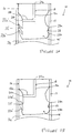
- valved container assembly 10 comprises an alternative valve 14'.
- the valved container assembly 10 is otherwise identical to that described above in relation to Figures 1A to 1C .
- the ribs or alternative formations described above in relation to Figure 3 may also be employed on the embodiment described in relation to Figures 2A and 2B .
- the alternative valve 14' has a permanent seal 16 identical to that described above in relation to Figures 1A to 1C , and comprises a resilient seal 22.
- the resilient seal 22 depicted in Figures 2A and 2B is formed of a pair of flexible elements 22a',22b' each extending radially from the valve 14' and arranged in axial alignment with one another.
- the resilient seal 22' of Figures 2A and 2B does not extend entirely circumferentially around the valve 14' but is otherwise identical to resilient seal 22. Instead, the resilient seal 22' extends partly around the circumference of the valve 14' and a second permanent seal 28 formed of a pair of flanges 28a,28b extending radially from the valve 14' extend around the remainder of the circumference of the valve 14' The second permanent seal 28 maintains a permanent seal between the valve 14' and the container 12 across the extent of the circumference that it extends.
- the valve 14' has a channel 18 that bypasses the permanent seal 16 and is formed of a first axial channel part 18a and a second channel part 18b arranged substantially perpendicularly to the first axial channel part 18a.
- a first opening 20a is associated with the first axial channel part 18a and a single second opening 20b is associated with the second channel part 18b.
- the channel 18 of Figures 2A and 2B is L-shaped in cross section, in contrast to the channel 18 of Figures 1A to 1C which is T-shaped in cross section.
- either channel arrangement may be used in either embodiment.
- other channel arrangements may be employed that bypass the permanent seal 16 from an outer radial position via an inner radial position that is radially inwards of the permanent seal 16.
- valve 14,14' is made from a deformable elastomeric material that is able to achieve a fluid tight seal with the container 12.
- the resilient seal 22' and the second permanent seal 28 are arranged relative to one another such that when the resilient seal 22' is in the sealing configuration (as shown in Figure 2A ) the combination of the resilient seal 22' and the second permanent seal 28 fluidly isolate the second opening 20b of the channel 18 from the first volume 24, and hence fluidly isolate the first volume 24 from the atmosphere.
- the resilient seal 22' permits a fluid pathway that fluidly connects the first volume 24 to an annulus circumferentially surrounding the valve 14' between the axial positions of the permanent seal 16 and the second permanent seal 28.
- axial ribs or similar formations may be arranged on the valve 14' on either side of the second opening 20b in each circumferential direction so as to form an axial channel that forms a circumferential boundary around the second opening 20b and seals with the container 12.
- the axial channel would be bound at a forward end by the permanent seal 16 and the axial channel would be bound at a rear end by resilient seal 22'. Since the second opening 20b is disposed within the bound axial channel, the second permanent seal 28 would not be necessary, however it is preferable that it still be present to minimise the risk of inadvertent fluid flow from the first volume 24 to the atmosphere.
- the valved container assembly 10 of the present invention may be formed by fixing the valve 14 in place in the container 12 by one of the methods described above. A fluid may then be introduced into the container 12 and the plunger element 32 may then be inserted to contain the fluid in the first volume 24 between the plunger element 32 and the valve 14.
- the first opening 20a of the valve may be provided with a spray head, nozzle or other suitable applicator to distribute the fluid exiting therefrom.
- valves 14,14' may be included in the container axially rearward of the first valve 14,14' to permit the separation and subsequent expulsion (which may be sequential) of two or more substances from the container.
- the substance contained in the first volume 24 is only in contact with a limited number of materials, for example the valve 14 and the container 12. With limited contact between the materials of the valved container assembly 10 and the substance contained in the first volume 24, it is easier to determine extractables and leachables.
- the container assembly 10 of the present invention affords easy and cost effective manufacture and does not necessarily require any specialist filling or assembly apparatus.
Landscapes
- Health & Medical Sciences (AREA)
- Engineering & Computer Science (AREA)
- Heart & Thoracic Surgery (AREA)
- Animal Behavior & Ethology (AREA)
- Public Health (AREA)
- Anesthesiology (AREA)
- Biomedical Technology (AREA)
- Veterinary Medicine (AREA)
- Hematology (AREA)
- Life Sciences & Earth Sciences (AREA)
- General Health & Medical Sciences (AREA)
- Pulmonology (AREA)
- Bioinformatics & Cheminformatics (AREA)
- Otolaryngology (AREA)
- Mechanical Engineering (AREA)
- Chemical & Material Sciences (AREA)
- Dispersion Chemistry (AREA)
- Containers And Packaging Bodies Having A Special Means To Remove Contents (AREA)
- Infusion, Injection, And Reservoir Apparatuses (AREA)
- Details Of Reciprocating Pumps (AREA)
- Medicinal Preparation (AREA)
- Filling Or Discharging Of Gas Storage Vessels (AREA)
Priority Applications (2)
| Application Number | Priority Date | Filing Date | Title |
|---|---|---|---|
| SI201330723T SI2817102T1 (sl) | 2012-02-22 | 2013-02-22 | Dispenzer,obsegajoč aktivacijski bat in izhodni protipovratni ventil |
| PL13708884T PL2817102T3 (pl) | 2012-02-22 | 2013-02-22 | Dozownik zawierający uruchamiający tłok i zewnętrzny kontrolny zawór |
Applications Claiming Priority (2)
| Application Number | Priority Date | Filing Date | Title |
|---|---|---|---|
| GB1203014.4A GB2499611B (en) | 2012-02-22 | 2012-02-22 | Valved container assembly |
| PCT/GB2013/050439 WO2013124670A1 (en) | 2012-02-22 | 2013-02-22 | Dispenser comprising actuating piston and outlet check valve |
Publications (2)
| Publication Number | Publication Date |
|---|---|
| EP2817102A1 EP2817102A1 (en) | 2014-12-31 |
| EP2817102B1 true EP2817102B1 (en) | 2017-07-19 |
Family
ID=45939985
Family Applications (1)
| Application Number | Title | Priority Date | Filing Date |
|---|---|---|---|
| EP13708884.5A Active EP2817102B1 (en) | 2012-02-22 | 2013-02-22 | Dispenser comprising actuating piston and outlet check valve |
Country Status (17)
| Country | Link |
|---|---|
| US (2) | US9833558B2 (enExample) |
| EP (1) | EP2817102B1 (enExample) |
| JP (1) | JP6182162B2 (enExample) |
| CN (1) | CN104136133B (enExample) |
| AU (1) | AU2013223805B2 (enExample) |
| CA (1) | CA2864418C (enExample) |
| CY (1) | CY1119395T1 (enExample) |
| DK (1) | DK2817102T3 (enExample) |
| ES (1) | ES2635873T3 (enExample) |
| GB (1) | GB2499611B (enExample) |
| HU (1) | HUE034891T2 (enExample) |
| IN (1) | IN2014DN07271A (enExample) |
| LT (1) | LT2817102T (enExample) |
| PL (1) | PL2817102T3 (enExample) |
| PT (1) | PT2817102T (enExample) |
| SI (1) | SI2817102T1 (enExample) |
| WO (1) | WO2013124670A1 (enExample) |
Families Citing this family (7)
| Publication number | Priority date | Publication date | Assignee | Title |
|---|---|---|---|---|
| GB2503028B (en) * | 2012-06-15 | 2018-10-24 | Consort Medical Plc | Valved container assembly |
| DE102018208110A1 (de) * | 2018-05-23 | 2019-11-28 | F. Holzer Gmbh | Abgabekopf und Abgabevorrichtung zur dosierten Abgabe flüssiger Präparate sowie Verwendungsmöglichkeiten |
| CN112426578B (zh) * | 2020-10-30 | 2022-02-08 | 中国人民解放军陆军军医大学第一附属医院 | 一种医用清洗结构 |
| DK4135830T3 (da) | 2020-12-23 | 2024-10-28 | Tolmar International Ltd | Systemer og fremgangsmåder til blanding af sprøjteventilanordninger |
| USD1029245S1 (en) | 2022-06-22 | 2024-05-28 | Tolmar International Limited | Syringe connector |
| DE102022129137A1 (de) | 2022-11-04 | 2024-05-08 | Fischerwerke Gmbh & Co. Kg | Mehrkammerkartusche |
| GB2628631A (en) * | 2023-03-31 | 2024-10-02 | Consort Medical Ltd | Improvements relating to the stoppering of containers |
Family Cites Families (10)
| Publication number | Priority date | Publication date | Assignee | Title |
|---|---|---|---|---|
| ATE19950T1 (de) * | 1982-12-20 | 1986-06-15 | Meditec Sa | Spritzampulle. |
| US5601077A (en) * | 1991-08-07 | 1997-02-11 | Becton, Dickinson And Company | Nasal syringe sprayer with removable dose limiting structure |
| US5405333A (en) * | 1992-12-28 | 1995-04-11 | Richmond; Frank M. | Liquid medicament bag with needleless connector fitting using boat assembly |
| FR2750051A1 (fr) | 1996-06-21 | 1997-12-26 | Debiotech Sa | Seringue medicale a piston libre |
| FR2780051B1 (fr) | 1998-06-23 | 2000-08-04 | Renault | Installation automatique de remplissage des reservoirs de carburant des vehicules automobiles |
| FR2793708B1 (fr) * | 1999-05-21 | 2001-08-03 | Valois Sa | Dispositif de distribution de produit fluide |
| GB0302536D0 (en) * | 2003-02-04 | 2003-03-12 | Bespak Plc | Container |
| US7874467B2 (en) * | 2005-11-03 | 2011-01-25 | Reseal International Limited Partnership | Metered drop push button dispenser system |
| US8016794B2 (en) * | 2006-03-09 | 2011-09-13 | Interrad Medical, Inc. | Anchor device and method |
| GB2441329B (en) * | 2006-09-04 | 2011-06-29 | Bespak Plc | Seal for a dispensing apparatus |
-
2012
- 2012-02-22 GB GB1203014.4A patent/GB2499611B/en not_active Expired - Fee Related
-
2013
- 2013-02-22 ES ES13708884.5T patent/ES2635873T3/es active Active
- 2013-02-22 WO PCT/GB2013/050439 patent/WO2013124670A1/en not_active Ceased
- 2013-02-22 SI SI201330723T patent/SI2817102T1/sl unknown
- 2013-02-22 US US14/380,241 patent/US9833558B2/en active Active
- 2013-02-22 CN CN201380010445.1A patent/CN104136133B/zh active Active
- 2013-02-22 IN IN7271DEN2014 patent/IN2014DN07271A/en unknown
- 2013-02-22 HU HUE13708884A patent/HUE034891T2/hu unknown
- 2013-02-22 PL PL13708884T patent/PL2817102T3/pl unknown
- 2013-02-22 JP JP2014558209A patent/JP6182162B2/ja active Active
- 2013-02-22 CA CA2864418A patent/CA2864418C/en active Active
- 2013-02-22 AU AU2013223805A patent/AU2013223805B2/en active Active
- 2013-02-22 DK DK13708884.5T patent/DK2817102T3/en active
- 2013-02-22 PT PT137088845T patent/PT2817102T/pt unknown
- 2013-02-22 LT LTEP13708884.5T patent/LT2817102T/lt unknown
- 2013-02-22 EP EP13708884.5A patent/EP2817102B1/en active Active
-
2017
- 2017-07-31 CY CY20171100822T patent/CY1119395T1/el unknown
- 2017-11-30 US US15/826,918 patent/US10646639B2/en active Active
Non-Patent Citations (1)
| Title |
|---|
| None * |
Also Published As
| Publication number | Publication date |
|---|---|
| GB201203014D0 (en) | 2012-04-04 |
| WO2013124670A1 (en) | 2013-08-29 |
| US20180078701A1 (en) | 2018-03-22 |
| AU2013223805B2 (en) | 2017-04-13 |
| GB2499611A (en) | 2013-08-28 |
| IN2014DN07271A (enExample) | 2015-04-24 |
| US20150045747A1 (en) | 2015-02-12 |
| ES2635873T3 (es) | 2017-10-05 |
| GB2499611B (en) | 2015-09-16 |
| LT2817102T (lt) | 2017-10-10 |
| CA2864418C (en) | 2020-07-14 |
| CY1119395T1 (el) | 2018-02-14 |
| CA2864418A1 (en) | 2013-08-29 |
| PL2817102T3 (pl) | 2017-12-29 |
| SI2817102T1 (sl) | 2017-11-30 |
| EP2817102A1 (en) | 2014-12-31 |
| HUE034891T2 (hu) | 2018-03-28 |
| US10646639B2 (en) | 2020-05-12 |
| PT2817102T (pt) | 2017-08-10 |
| JP6182162B2 (ja) | 2017-08-16 |
| CN104136133A (zh) | 2014-11-05 |
| US9833558B2 (en) | 2017-12-05 |
| CN104136133B (zh) | 2016-11-16 |
| AU2013223805A1 (en) | 2014-09-11 |
| JP2015516178A (ja) | 2015-06-11 |
| DK2817102T3 (en) | 2017-08-28 |
Similar Documents
| Publication | Publication Date | Title |
|---|---|---|
| US10646639B2 (en) | Valved container assembly | |
| US10080882B2 (en) | Valved container assembly | |
| EP2817043B1 (en) | Improved syringe assembly | |
| US9757750B2 (en) | Medicinal device with container | |
| KR980008348A (ko) | 매체 분배기 | |
| HK1242239A1 (en) | Improved mixing syringe assembly |
Legal Events
| Date | Code | Title | Description |
|---|---|---|---|
| PUAI | Public reference made under article 153(3) epc to a published international application that has entered the european phase |
Free format text: ORIGINAL CODE: 0009012 |
|
| 17P | Request for examination filed |
Effective date: 20140912 |
|
| AK | Designated contracting states |
Kind code of ref document: A1 Designated state(s): AL AT BE BG CH CY CZ DE DK EE ES FI FR GB GR HR HU IE IS IT LI LT LU LV MC MK MT NL NO PL PT RO RS SE SI SK SM TR |
|
| AX | Request for extension of the european patent |
Extension state: BA ME |
|
| DAX | Request for extension of the european patent (deleted) | ||
| GRAP | Despatch of communication of intention to grant a patent |
Free format text: ORIGINAL CODE: EPIDOSNIGR1 |
|
| RIC1 | Information provided on ipc code assigned before grant |
Ipc: A61M 15/00 20060101ALI20170221BHEP Ipc: B05B 11/02 20060101ALI20170221BHEP Ipc: B05B 11/00 20060101AFI20170221BHEP |
|
| INTG | Intention to grant announced |
Effective date: 20170314 |
|
| GRAS | Grant fee paid |
Free format text: ORIGINAL CODE: EPIDOSNIGR3 |
|
| GRAA | (expected) grant |
Free format text: ORIGINAL CODE: 0009210 |
|
| AK | Designated contracting states |
Kind code of ref document: B1 Designated state(s): AL AT BE BG CH CY CZ DE DK EE ES FI FR GB GR HR HU IE IS IT LI LT LU LV MC MK MT NL NO PL PT RO RS SE SI SK SM TR |
|
| REG | Reference to a national code |
Ref country code: GB Ref legal event code: FG4D |
|
| REG | Reference to a national code |
Ref country code: CH Ref legal event code: EP |
|
| REG | Reference to a national code |
Ref country code: IE Ref legal event code: FG4D Ref country code: RO Ref legal event code: EPE |
|
| REG | Reference to a national code |
Ref country code: PT Ref legal event code: SC4A Ref document number: 2817102 Country of ref document: PT Date of ref document: 20170810 Kind code of ref document: T Free format text: AVAILABILITY OF NATIONAL TRANSLATION Effective date: 20170804 |
|
| REG | Reference to a national code |
Ref country code: AT Ref legal event code: REF Ref document number: 909874 Country of ref document: AT Kind code of ref document: T Effective date: 20170815 |
|
| REG | Reference to a national code |
Ref country code: NL Ref legal event code: FP |
|
| REG | Reference to a national code |
Ref country code: DK Ref legal event code: T3 Effective date: 20170822 |
|
| REG | Reference to a national code |
Ref country code: SE Ref legal event code: TRGR |
|
| REG | Reference to a national code |
Ref country code: DE Ref legal event code: R096 Ref document number: 602013023691 Country of ref document: DE |
|
| REG | Reference to a national code |
Ref country code: CH Ref legal event code: NV Representative=s name: MICHELI AND CIE SA, CH |
|
| REG | Reference to a national code |
Ref country code: ES Ref legal event code: FG2A Ref document number: 2635873 Country of ref document: ES Kind code of ref document: T3 Effective date: 20171005 |
|
| REG | Reference to a national code |
Ref country code: EE Ref legal event code: FG4A Ref document number: E014260 Country of ref document: EE Effective date: 20170804 |
|
| REG | Reference to a national code |
Ref country code: NO Ref legal event code: T2 Effective date: 20170719 |
|
| REG | Reference to a national code |
Ref country code: SK Ref legal event code: T3 Ref document number: E 24993 Country of ref document: SK |
|
| PG25 | Lapsed in a contracting state [announced via postgrant information from national office to epo] |
Ref country code: HR Free format text: LAPSE BECAUSE OF FAILURE TO SUBMIT A TRANSLATION OF THE DESCRIPTION OR TO PAY THE FEE WITHIN THE PRESCRIBED TIME-LIMIT Effective date: 20170719 |
|
| REG | Reference to a national code |
Ref country code: FR Ref legal event code: PLFP Year of fee payment: 6 |
|
| PG25 | Lapsed in a contracting state [announced via postgrant information from national office to epo] |
Ref country code: RS Free format text: LAPSE BECAUSE OF FAILURE TO SUBMIT A TRANSLATION OF THE DESCRIPTION OR TO PAY THE FEE WITHIN THE PRESCRIBED TIME-LIMIT Effective date: 20170719 Ref country code: IS Free format text: LAPSE BECAUSE OF FAILURE TO SUBMIT A TRANSLATION OF THE DESCRIPTION OR TO PAY THE FEE WITHIN THE PRESCRIBED TIME-LIMIT Effective date: 20171119 |
|
| REG | Reference to a national code |
Ref country code: GR Ref legal event code: EP Ref document number: 20170402516 Country of ref document: GR Effective date: 20180309 |
|
| REG | Reference to a national code |
Ref country code: HU Ref legal event code: AG4A Ref document number: E034891 Country of ref document: HU |
|
| REG | Reference to a national code |
Ref country code: DE Ref legal event code: R097 Ref document number: 602013023691 Country of ref document: DE |
|
| PGFP | Annual fee paid to national office [announced via postgrant information from national office to epo] |
Ref country code: NO Payment date: 20180216 Year of fee payment: 6 |
|
| PLBE | No opposition filed within time limit |
Free format text: ORIGINAL CODE: 0009261 |
|
| STAA | Information on the status of an ep patent application or granted ep patent |
Free format text: STATUS: NO OPPOSITION FILED WITHIN TIME LIMIT |
|
| PG25 | Lapsed in a contracting state [announced via postgrant information from national office to epo] |
Ref country code: SM Free format text: LAPSE BECAUSE OF FAILURE TO SUBMIT A TRANSLATION OF THE DESCRIPTION OR TO PAY THE FEE WITHIN THE PRESCRIBED TIME-LIMIT Effective date: 20170719 |
|
| PGFP | Annual fee paid to national office [announced via postgrant information from national office to epo] |
Ref country code: MC Payment date: 20180131 Year of fee payment: 6 |
|
| 26N | No opposition filed |
Effective date: 20180420 |
|
| REG | Reference to a national code |
Ref country code: NO Ref legal event code: MMEP |
|
| PG25 | Lapsed in a contracting state [announced via postgrant information from national office to epo] |
Ref country code: MC Free format text: LAPSE BECAUSE OF NON-PAYMENT OF DUE FEES Effective date: 20190228 Ref country code: NO Free format text: LAPSE BECAUSE OF NON-PAYMENT OF DUE FEES Effective date: 20190228 |
|
| PG25 | Lapsed in a contracting state [announced via postgrant information from national office to epo] |
Ref country code: MT Free format text: LAPSE BECAUSE OF NON-PAYMENT OF DUE FEES Effective date: 20180222 |
|
| REG | Reference to a national code |
Ref country code: AT Ref legal event code: UEP Ref document number: 909874 Country of ref document: AT Kind code of ref document: T Effective date: 20170719 |
|
| PG25 | Lapsed in a contracting state [announced via postgrant information from national office to epo] |
Ref country code: MK Free format text: LAPSE BECAUSE OF NON-PAYMENT OF DUE FEES Effective date: 20170719 |
|
| PG25 | Lapsed in a contracting state [announced via postgrant information from national office to epo] |
Ref country code: AL Free format text: LAPSE BECAUSE OF FAILURE TO SUBMIT A TRANSLATION OF THE DESCRIPTION OR TO PAY THE FEE WITHIN THE PRESCRIBED TIME-LIMIT Effective date: 20170719 |
|
| P01 | Opt-out of the competence of the unified patent court (upc) registered |
Effective date: 20230317 |
|
| PGFP | Annual fee paid to national office [announced via postgrant information from national office to epo] |
Ref country code: BG Payment date: 20250114 Year of fee payment: 13 |
|
| PGFP | Annual fee paid to national office [announced via postgrant information from national office to epo] |
Ref country code: SI Payment date: 20250127 Year of fee payment: 13 |
|
| PGFP | Annual fee paid to national office [announced via postgrant information from national office to epo] |
Ref country code: ES Payment date: 20250512 Year of fee payment: 13 |
|
| PGFP | Annual fee paid to national office [announced via postgrant information from national office to epo] |
Ref country code: DK Payment date: 20251223 Year of fee payment: 14 |
|
| REG | Reference to a national code |
Ref country code: CH Ref legal event code: U11 Free format text: ST27 STATUS EVENT CODE: U-0-0-U10-U11 (AS PROVIDED BY THE NATIONAL OFFICE) Effective date: 20260301 |
|
| PGFP | Annual fee paid to national office [announced via postgrant information from national office to epo] |
Ref country code: LU Payment date: 20260204 Year of fee payment: 14 Ref country code: NL Payment date: 20260205 Year of fee payment: 14 |
|
| PGFP | Annual fee paid to national office [announced via postgrant information from national office to epo] |
Ref country code: HU Payment date: 20260127 Year of fee payment: 14 |
|
| PGFP | Annual fee paid to national office [announced via postgrant information from national office to epo] |
Ref country code: SE Payment date: 20260129 Year of fee payment: 14 |
|
| PGFP | Annual fee paid to national office [announced via postgrant information from national office to epo] |
Ref country code: GB Payment date: 20260213 Year of fee payment: 14 Ref country code: LT Payment date: 20260123 Year of fee payment: 14 |
|
| PGFP | Annual fee paid to national office [announced via postgrant information from national office to epo] |
Ref country code: DE Payment date: 20260206 Year of fee payment: 14 Ref country code: IE Payment date: 20260206 Year of fee payment: 14 |
|
| PGFP | Annual fee paid to national office [announced via postgrant information from national office to epo] |
Ref country code: AT Payment date: 20260206 Year of fee payment: 14 |
|
| PGFP | Annual fee paid to national office [announced via postgrant information from national office to epo] |
Ref country code: RO Payment date: 20260126 Year of fee payment: 14 Ref country code: BE Payment date: 20260204 Year of fee payment: 14 Ref country code: FI Payment date: 20260209 Year of fee payment: 14 Ref country code: IT Payment date: 20260130 Year of fee payment: 14 |
|
| PGFP | Annual fee paid to national office [announced via postgrant information from national office to epo] |
Ref country code: FR Payment date: 20260213 Year of fee payment: 14 |
|
| PGFP | Annual fee paid to national office [announced via postgrant information from national office to epo] |
Ref country code: TR Payment date: 20260129 Year of fee payment: 14 |
|
| PGFP | Annual fee paid to national office [announced via postgrant information from national office to epo] |
Ref country code: PT Payment date: 20260213 Year of fee payment: 14 Ref country code: CZ Payment date: 20260123 Year of fee payment: 14 Ref country code: CH Payment date: 20260301 Year of fee payment: 14 |
|
| PGFP | Annual fee paid to national office [announced via postgrant information from national office to epo] |
Ref country code: GR Payment date: 20260206 Year of fee payment: 14 Ref country code: PL Payment date: 20260128 Year of fee payment: 14 Ref country code: CY Payment date: 20260126 Year of fee payment: 14 |
|
| PGFP | Annual fee paid to national office [announced via postgrant information from national office to epo] |
Ref country code: EE Payment date: 20260210 Year of fee payment: 14 Ref country code: SK Payment date: 20260123 Year of fee payment: 14 Ref country code: LV Payment date: 20260206 Year of fee payment: 14 |