EP2817088B1 - Microcanal avec dispositif d'ouverture et/ou fermeture et/ou pompage - Google Patents
Microcanal avec dispositif d'ouverture et/ou fermeture et/ou pompage Download PDFInfo
- Publication number
- EP2817088B1 EP2817088B1 EP13707596.6A EP13707596A EP2817088B1 EP 2817088 B1 EP2817088 B1 EP 2817088B1 EP 13707596 A EP13707596 A EP 13707596A EP 2817088 B1 EP2817088 B1 EP 2817088B1
- Authority
- EP
- European Patent Office
- Prior art keywords
- microchannel
- substrate
- polymer
- hydrogel
- film
- Prior art date
- Legal status (The legal status is an assumption and is not a legal conclusion. Google has not performed a legal analysis and makes no representation as to the accuracy of the status listed.)
- Active
Links
Images



Classifications
-
- F—MECHANICAL ENGINEERING; LIGHTING; HEATING; WEAPONS; BLASTING
- F16—ENGINEERING ELEMENTS AND UNITS; GENERAL MEASURES FOR PRODUCING AND MAINTAINING EFFECTIVE FUNCTIONING OF MACHINES OR INSTALLATIONS; THERMAL INSULATION IN GENERAL
- F16K—VALVES; TAPS; COCKS; ACTUATING-FLOATS; DEVICES FOR VENTING OR AERATING
- F16K99/00—Subject matter not provided for in other groups of this subclass
- F16K99/0001—Microvalves
- F16K99/0003—Constructional types of microvalves; Details of the cutting-off member
- F16K99/0026—Valves using channel deformation
-
- B—PERFORMING OPERATIONS; TRANSPORTING
- B01—PHYSICAL OR CHEMICAL PROCESSES OR APPARATUS IN GENERAL
- B01L—CHEMICAL OR PHYSICAL LABORATORY APPARATUS FOR GENERAL USE
- B01L3/00—Containers or dishes for laboratory use, e.g. laboratory glassware; Droppers
- B01L3/50—Containers for the purpose of retaining a material to be analysed, e.g. test tubes
- B01L3/502—Containers for the purpose of retaining a material to be analysed, e.g. test tubes with fluid transport, e.g. in multi-compartment structures
- B01L3/5027—Containers for the purpose of retaining a material to be analysed, e.g. test tubes with fluid transport, e.g. in multi-compartment structures by integrated microfluidic structures, i.e. dimensions of channels and chambers are such that surface tension forces are important, e.g. lab-on-a-chip
- B01L3/50273—Containers for the purpose of retaining a material to be analysed, e.g. test tubes with fluid transport, e.g. in multi-compartment structures by integrated microfluidic structures, i.e. dimensions of channels and chambers are such that surface tension forces are important, e.g. lab-on-a-chip characterised by the means or forces applied to move the fluids
-
- B—PERFORMING OPERATIONS; TRANSPORTING
- B01—PHYSICAL OR CHEMICAL PROCESSES OR APPARATUS IN GENERAL
- B01L—CHEMICAL OR PHYSICAL LABORATORY APPARATUS FOR GENERAL USE
- B01L3/00—Containers or dishes for laboratory use, e.g. laboratory glassware; Droppers
- B01L3/50—Containers for the purpose of retaining a material to be analysed, e.g. test tubes
- B01L3/502—Containers for the purpose of retaining a material to be analysed, e.g. test tubes with fluid transport, e.g. in multi-compartment structures
- B01L3/5027—Containers for the purpose of retaining a material to be analysed, e.g. test tubes with fluid transport, e.g. in multi-compartment structures by integrated microfluidic structures, i.e. dimensions of channels and chambers are such that surface tension forces are important, e.g. lab-on-a-chip
- B01L3/502738—Containers for the purpose of retaining a material to be analysed, e.g. test tubes with fluid transport, e.g. in multi-compartment structures by integrated microfluidic structures, i.e. dimensions of channels and chambers are such that surface tension forces are important, e.g. lab-on-a-chip characterised by integrated valves
-
- F—MECHANICAL ENGINEERING; LIGHTING; HEATING; WEAPONS; BLASTING
- F04—POSITIVE - DISPLACEMENT MACHINES FOR LIQUIDS; PUMPS FOR LIQUIDS OR ELASTIC FLUIDS
- F04B—POSITIVE-DISPLACEMENT MACHINES FOR LIQUIDS; PUMPS
- F04B19/00—Machines or pumps having pertinent characteristics not provided for in, or of interest apart from, groups F04B1/00 - F04B17/00
- F04B19/006—Micropumps
-
- F—MECHANICAL ENGINEERING; LIGHTING; HEATING; WEAPONS; BLASTING
- F16—ENGINEERING ELEMENTS AND UNITS; GENERAL MEASURES FOR PRODUCING AND MAINTAINING EFFECTIVE FUNCTIONING OF MACHINES OR INSTALLATIONS; THERMAL INSULATION IN GENERAL
- F16K—VALVES; TAPS; COCKS; ACTUATING-FLOATS; DEVICES FOR VENTING OR AERATING
- F16K99/00—Subject matter not provided for in other groups of this subclass
- F16K99/0001—Microvalves
- F16K99/0003—Constructional types of microvalves; Details of the cutting-off member
- F16K99/0032—Constructional types of microvalves; Details of the cutting-off member using phase transition or influencing viscosity
-
- F—MECHANICAL ENGINEERING; LIGHTING; HEATING; WEAPONS; BLASTING
- F16—ENGINEERING ELEMENTS AND UNITS; GENERAL MEASURES FOR PRODUCING AND MAINTAINING EFFECTIVE FUNCTIONING OF MACHINES OR INSTALLATIONS; THERMAL INSULATION IN GENERAL
- F16K—VALVES; TAPS; COCKS; ACTUATING-FLOATS; DEVICES FOR VENTING OR AERATING
- F16K99/00—Subject matter not provided for in other groups of this subclass
- F16K99/0001—Microvalves
- F16K99/0034—Operating means specially adapted for microvalves
- F16K99/0036—Operating means specially adapted for microvalves operated by temperature variations
-
- F—MECHANICAL ENGINEERING; LIGHTING; HEATING; WEAPONS; BLASTING
- F16—ENGINEERING ELEMENTS AND UNITS; GENERAL MEASURES FOR PRODUCING AND MAINTAINING EFFECTIVE FUNCTIONING OF MACHINES OR INSTALLATIONS; THERMAL INSULATION IN GENERAL
- F16K—VALVES; TAPS; COCKS; ACTUATING-FLOATS; DEVICES FOR VENTING OR AERATING
- F16K99/00—Subject matter not provided for in other groups of this subclass
- F16K99/0001—Microvalves
- F16K99/0034—Operating means specially adapted for microvalves
- F16K99/0036—Operating means specially adapted for microvalves operated by temperature variations
- F16K99/0038—Operating means specially adapted for microvalves operated by temperature variations using shape memory alloys
-
- F—MECHANICAL ENGINEERING; LIGHTING; HEATING; WEAPONS; BLASTING
- F16—ENGINEERING ELEMENTS AND UNITS; GENERAL MEASURES FOR PRODUCING AND MAINTAINING EFFECTIVE FUNCTIONING OF MACHINES OR INSTALLATIONS; THERMAL INSULATION IN GENERAL
- F16K—VALVES; TAPS; COCKS; ACTUATING-FLOATS; DEVICES FOR VENTING OR AERATING
- F16K99/00—Subject matter not provided for in other groups of this subclass
- F16K99/0001—Microvalves
- F16K99/0034—Operating means specially adapted for microvalves
- F16K99/0042—Electric operating means therefor
- F16K99/0049—Electric operating means therefor using an electroactive polymer [EAP]
-
- F—MECHANICAL ENGINEERING; LIGHTING; HEATING; WEAPONS; BLASTING
- F16—ENGINEERING ELEMENTS AND UNITS; GENERAL MEASURES FOR PRODUCING AND MAINTAINING EFFECTIVE FUNCTIONING OF MACHINES OR INSTALLATIONS; THERMAL INSULATION IN GENERAL
- F16K—VALVES; TAPS; COCKS; ACTUATING-FLOATS; DEVICES FOR VENTING OR AERATING
- F16K99/00—Subject matter not provided for in other groups of this subclass
- F16K99/0001—Microvalves
- F16K99/0034—Operating means specially adapted for microvalves
- F16K99/0055—Operating means specially adapted for microvalves actuated by fluids
- F16K99/0061—Operating means specially adapted for microvalves actuated by fluids actuated by an expanding gas or liquid volume
-
- B—PERFORMING OPERATIONS; TRANSPORTING
- B01—PHYSICAL OR CHEMICAL PROCESSES OR APPARATUS IN GENERAL
- B01L—CHEMICAL OR PHYSICAL LABORATORY APPARATUS FOR GENERAL USE
- B01L2200/00—Solutions for specific problems relating to chemical or physical laboratory apparatus
- B01L2200/10—Integrating sample preparation and analysis in single entity, e.g. lab-on-a-chip concept
-
- B—PERFORMING OPERATIONS; TRANSPORTING
- B01—PHYSICAL OR CHEMICAL PROCESSES OR APPARATUS IN GENERAL
- B01L—CHEMICAL OR PHYSICAL LABORATORY APPARATUS FOR GENERAL USE
- B01L2300/00—Additional constructional details
- B01L2300/08—Geometry, shape and general structure
- B01L2300/0809—Geometry, shape and general structure rectangular shaped
- B01L2300/0816—Cards, e.g. flat sample carriers usually with flow in two horizontal directions
-
- B—PERFORMING OPERATIONS; TRANSPORTING
- B01—PHYSICAL OR CHEMICAL PROCESSES OR APPARATUS IN GENERAL
- B01L—CHEMICAL OR PHYSICAL LABORATORY APPARATUS FOR GENERAL USE
- B01L2300/00—Additional constructional details
- B01L2300/08—Geometry, shape and general structure
- B01L2300/0861—Configuration of multiple channels and/or chambers in a single devices
-
- B—PERFORMING OPERATIONS; TRANSPORTING
- B01—PHYSICAL OR CHEMICAL PROCESSES OR APPARATUS IN GENERAL
- B01L—CHEMICAL OR PHYSICAL LABORATORY APPARATUS FOR GENERAL USE
- B01L2300/00—Additional constructional details
- B01L2300/08—Geometry, shape and general structure
- B01L2300/0861—Configuration of multiple channels and/or chambers in a single devices
- B01L2300/0867—Multiple inlets and one sample wells, e.g. mixing, dilution
-
- B—PERFORMING OPERATIONS; TRANSPORTING
- B01—PHYSICAL OR CHEMICAL PROCESSES OR APPARATUS IN GENERAL
- B01L—CHEMICAL OR PHYSICAL LABORATORY APPARATUS FOR GENERAL USE
- B01L2300/00—Additional constructional details
- B01L2300/08—Geometry, shape and general structure
- B01L2300/0861—Configuration of multiple channels and/or chambers in a single devices
- B01L2300/087—Multiple sequential chambers
-
- B—PERFORMING OPERATIONS; TRANSPORTING
- B01—PHYSICAL OR CHEMICAL PROCESSES OR APPARATUS IN GENERAL
- B01L—CHEMICAL OR PHYSICAL LABORATORY APPARATUS FOR GENERAL USE
- B01L2300/00—Additional constructional details
- B01L2300/16—Surface properties and coatings
- B01L2300/161—Control and use of surface tension forces, e.g. hydrophobic, hydrophilic
-
- B—PERFORMING OPERATIONS; TRANSPORTING
- B01—PHYSICAL OR CHEMICAL PROCESSES OR APPARATUS IN GENERAL
- B01L—CHEMICAL OR PHYSICAL LABORATORY APPARATUS FOR GENERAL USE
- B01L2400/00—Moving or stopping fluids
- B01L2400/04—Moving fluids with specific forces or mechanical means
- B01L2400/0403—Moving fluids with specific forces or mechanical means specific forces
- B01L2400/0415—Moving fluids with specific forces or mechanical means specific forces electrical forces, e.g. electrokinetic
- B01L2400/0421—Moving fluids with specific forces or mechanical means specific forces electrical forces, e.g. electrokinetic electrophoretic flow
-
- B—PERFORMING OPERATIONS; TRANSPORTING
- B01—PHYSICAL OR CHEMICAL PROCESSES OR APPARATUS IN GENERAL
- B01L—CHEMICAL OR PHYSICAL LABORATORY APPARATUS FOR GENERAL USE
- B01L2400/00—Moving or stopping fluids
- B01L2400/04—Moving fluids with specific forces or mechanical means
- B01L2400/0475—Moving fluids with specific forces or mechanical means specific mechanical means and fluid pressure
- B01L2400/0481—Moving fluids with specific forces or mechanical means specific mechanical means and fluid pressure squeezing of channels or chambers
-
- B—PERFORMING OPERATIONS; TRANSPORTING
- B01—PHYSICAL OR CHEMICAL PROCESSES OR APPARATUS IN GENERAL
- B01L—CHEMICAL OR PHYSICAL LABORATORY APPARATUS FOR GENERAL USE
- B01L2400/00—Moving or stopping fluids
- B01L2400/06—Valves, specific forms thereof
- B01L2400/0677—Valves, specific forms thereof phase change valves; Meltable, freezing, dissolvable plugs; Destructible barriers
-
- B—PERFORMING OPERATIONS; TRANSPORTING
- B01—PHYSICAL OR CHEMICAL PROCESSES OR APPARATUS IN GENERAL
- B01L—CHEMICAL OR PHYSICAL LABORATORY APPARATUS FOR GENERAL USE
- B01L3/00—Containers or dishes for laboratory use, e.g. laboratory glassware; Droppers
- B01L3/50—Containers for the purpose of retaining a material to be analysed, e.g. test tubes
- B01L3/502—Containers for the purpose of retaining a material to be analysed, e.g. test tubes with fluid transport, e.g. in multi-compartment structures
- B01L3/5027—Containers for the purpose of retaining a material to be analysed, e.g. test tubes with fluid transport, e.g. in multi-compartment structures by integrated microfluidic structures, i.e. dimensions of channels and chambers are such that surface tension forces are important, e.g. lab-on-a-chip
- B01L3/502769—Containers for the purpose of retaining a material to be analysed, e.g. test tubes with fluid transport, e.g. in multi-compartment structures by integrated microfluidic structures, i.e. dimensions of channels and chambers are such that surface tension forces are important, e.g. lab-on-a-chip characterised by multiphase flow arrangements
- B01L3/502776—Containers for the purpose of retaining a material to be analysed, e.g. test tubes with fluid transport, e.g. in multi-compartment structures by integrated microfluidic structures, i.e. dimensions of channels and chambers are such that surface tension forces are important, e.g. lab-on-a-chip characterised by multiphase flow arrangements specially adapted for focusing or laminating flows
-
- B—PERFORMING OPERATIONS; TRANSPORTING
- B01—PHYSICAL OR CHEMICAL PROCESSES OR APPARATUS IN GENERAL
- B01L—CHEMICAL OR PHYSICAL LABORATORY APPARATUS FOR GENERAL USE
- B01L7/00—Heating or cooling apparatus; Heat insulating devices
- B01L7/52—Heating or cooling apparatus; Heat insulating devices with provision for submitting samples to a predetermined sequence of different temperatures, e.g. for treating nucleic acid samples
-
- F—MECHANICAL ENGINEERING; LIGHTING; HEATING; WEAPONS; BLASTING
- F16—ENGINEERING ELEMENTS AND UNITS; GENERAL MEASURES FOR PRODUCING AND MAINTAINING EFFECTIVE FUNCTIONING OF MACHINES OR INSTALLATIONS; THERMAL INSULATION IN GENERAL
- F16K—VALVES; TAPS; COCKS; ACTUATING-FLOATS; DEVICES FOR VENTING OR AERATING
- F16K99/00—Subject matter not provided for in other groups of this subclass
- F16K2099/0073—Fabrication methods specifically adapted for microvalves
- F16K2099/0078—Fabrication methods specifically adapted for microvalves using moulding or stamping
-
- F—MECHANICAL ENGINEERING; LIGHTING; HEATING; WEAPONS; BLASTING
- F16—ENGINEERING ELEMENTS AND UNITS; GENERAL MEASURES FOR PRODUCING AND MAINTAINING EFFECTIVE FUNCTIONING OF MACHINES OR INSTALLATIONS; THERMAL INSULATION IN GENERAL
- F16K—VALVES; TAPS; COCKS; ACTUATING-FLOATS; DEVICES FOR VENTING OR AERATING
- F16K99/00—Subject matter not provided for in other groups of this subclass
- F16K2099/0073—Fabrication methods specifically adapted for microvalves
- F16K2099/008—Multi-layer fabrications
-
- F—MECHANICAL ENGINEERING; LIGHTING; HEATING; WEAPONS; BLASTING
- F16—ENGINEERING ELEMENTS AND UNITS; GENERAL MEASURES FOR PRODUCING AND MAINTAINING EFFECTIVE FUNCTIONING OF MACHINES OR INSTALLATIONS; THERMAL INSULATION IN GENERAL
- F16K—VALVES; TAPS; COCKS; ACTUATING-FLOATS; DEVICES FOR VENTING OR AERATING
- F16K99/00—Subject matter not provided for in other groups of this subclass
- F16K2099/0082—Microvalves adapted for a particular use
- F16K2099/0094—Micropumps
-
- Y—GENERAL TAGGING OF NEW TECHNOLOGICAL DEVELOPMENTS; GENERAL TAGGING OF CROSS-SECTIONAL TECHNOLOGIES SPANNING OVER SEVERAL SECTIONS OF THE IPC; TECHNICAL SUBJECTS COVERED BY FORMER USPC CROSS-REFERENCE ART COLLECTIONS [XRACs] AND DIGESTS
- Y10—TECHNICAL SUBJECTS COVERED BY FORMER USPC
- Y10T—TECHNICAL SUBJECTS COVERED BY FORMER US CLASSIFICATION
- Y10T137/00—Fluid handling
- Y10T137/206—Flow affected by fluid contact, energy field or coanda effect [e.g., pure fluid device or system]
- Y10T137/218—Means to regulate or vary operation of device
- Y10T137/2191—By non-fluid energy field affecting input [e.g., transducer]
-
- Y—GENERAL TAGGING OF NEW TECHNOLOGICAL DEVELOPMENTS; GENERAL TAGGING OF CROSS-SECTIONAL TECHNOLOGIES SPANNING OVER SEVERAL SECTIONS OF THE IPC; TECHNICAL SUBJECTS COVERED BY FORMER USPC CROSS-REFERENCE ART COLLECTIONS [XRACs] AND DIGESTS
- Y10—TECHNICAL SUBJECTS COVERED BY FORMER USPC
- Y10T—TECHNICAL SUBJECTS COVERED BY FORMER US CLASSIFICATION
- Y10T137/00—Fluid handling
- Y10T137/206—Flow affected by fluid contact, energy field or coanda effect [e.g., pure fluid device or system]
- Y10T137/218—Means to regulate or vary operation of device
- Y10T137/2191—By non-fluid energy field affecting input [e.g., transducer]
- Y10T137/2196—Acoustical or thermal energy
Definitions
- the present invention relates to the field of microfluidic systems, and more particularly a microchannel, and to its manufacturing method, comprising an opening and / or closing and / or pumping device.
- Microfluidic systems are more and more used in fields as varied as chemistry, biology, physics, analysis, diagnosis, screening ....
- the substrates used are made of solid material chosen from glass, silicon, metal, polymers, or a combination of all these materials.
- microchannels can be etched into the substrate by any known method. A solid piece or a thin layer then covers the substrate, thus delimiting the geometry of the microchannels.
- the microchannels can also be obtained by molding an elastomer in a suitable mold and then placed on a substrate. These microchannels can be arranged to form a network in which fluids circulate.
- valves and pumps In order to be able to control the movements of fluids, it is often advantageous to integrate valves and pumps in the microfluidic network.
- the stimulus in question is applied to the pillars, which has the effect of causing the layer to swell until the microsystem is closed.
- the patent US 7,988,685 implements, as in the patent US 6,408,878 , two networks of micochannels separated by a membrane but the control is ensured not by a variation of the pressure in one of the two networks but by the swelling caused by a hydrogel present in the microchannel of control, which deforms the membrane and comes to close the channel.
- WO 01/075060 A2 and DE 101 57 317 A1 also proposes a process for manufacturing microvalves used to close or open microchannels.
- the present invention therefore aims to overcome one or more of the drawbacks of the prior art by proposing an opening and / or closing and / or pumping microchannel device.
- the device is simple to implement and does not require a complex step in its production.
- the present invention provides a microchannel formed at the interface of two layers of material, at least one of the two materials being a substrate, a polymer film being fixed on the substrate layer in a volume of the microchannel; said polymer film being formed of a hydrogel type material capable of undergoing volume variations under the action of an external stimulus, the layer of hydrogel type polymer being grafted onto the substrate by covalent bond.
- the presence of the hydrogel in the microchannels makes it possible, under the effect of one of the stimuli described, to close or open the microchannels. It is therefore the layer of polymer grafted in the microchannel which plays the role of microvalves or micropumps at the microchannel level.
- the covalent bond allows vertical swelling, and overcomes the mechanical shear stresses between the hydrogel and the surface of the substrate to which it is attached.
- the hydrogel type polymer is chosen from those sensitive to variations in temperature, light, electric field or pH.
- the invention also relates to a microfluidic system characterized in that it comprises at least one microchannel according to the invention.
- the invention also relates to a manufacturing method comprising at least one step of covalent bonding of a hydrogel-type polymer on a substrate, the hydrogel-type polymer being capable of undergoing volume variations under the action of an external stimulus, on one face of a substrate arranged in the volume of a microchannel formed at the interface of two layers of material, at least one of the two materials being the substrate.
- the step of fixing the hydrogel-type polymer on the substrate is carried out outside the microchannel.
- the grafting step comprises two phases, a phase of chemical modification of the hydrogel-type polymer and a phase of modification of the surface chemical properties of the substrate.
- the grafting step is preceded by a phase of synthesis of the hydrogel type polymer.
- the hydrogel type polymer is synthesized by crosslinking between functionalized polymer chains, the synthesis of the polymer chains being carried out by radical copolymerization.
- the chemical modification of the polymers is an amidation by means of an amine comprising at least one vinyl group.
- microchannels concerned by the present invention are made by a step of shaping a material.
- this shaping step can be carried out by etching, by micro-machining of glass or silicon, by different molding techniques with polymers: thermoforming or hot molding, ablation of polymer, or molding of polymer.
- the materials used can be any type of polymer, and for example polymers such as polystyrene (PS), polycarbonate (PC), polyvinyl chloride (PVC), Cyclic Olefin Copolymers (COC), Poly (Metyl methacrylate) (PMMA), Thermoset Polyester (TPE), Polyurethane Methacrylate (PUMA), or Acrylonitrile Butadiene Styrenes.
- polymers such as polystyrene (PS), polycarbonate (PC), polyvinyl chloride (PVC), Cyclic Olefin Copolymers (COC), Poly (Metyl methacrylate) (PMMA), Thermoset Polyester (TPE), Polyurethane Methacrylate (PUMA), or Acrylonitrile Butadiene Styrenes.
- PS polystyrene
- PC polycarbonate
- PVC polyvinyl chloride
- COC Cyclic Olefin Copolymers
- PMMA Poly (Mety
- the materials can also be chosen from photocrosslinkable or photosensitive liquids or glues, for example Norland Optical Adhesive (NOA).
- NOA Norland Optical Adhesive
- the material is positioned on a layer of a flat substrate on which a layer of a hydrogel-type polymer is covalently grafted.
- the molded material is positioned so that the recess, created by molding, etching or machining, forms a microfluidic channel on the side of the hydrogel.
- microchannel (7, 17) ( figures 5 and 9 ) is thus formed at the interface of two layers of material, at least one of the two materials being a substrate (9, 14, 15, 16). A volume of the microchannel is contained in the recess formed in the material.
- the hydrogel-type polymer to be grafted used in the context of the present invention and contained in the volume of the microchannel, is a polymer insoluble in water and capable of constituting a gel with high absorbency in the presence of a liquid or fluid. These polymers have a high degree of flexibility. Indeed, it is possible to increase their volume under the action of a stimulus of the type variation of temperature, light, pH, electric field.
- the hydrogel-type polymer to be grafted is grafted so as to be able to expand perpendicular to its plane of attachment, that is to say to be able to swell vertically. The stresses on the hydrogel-type polymer are therefore perpendicular to the surface and are not likely to cause breaks in the attachment to the support.
- the hydrogel type polymer is grafted with covalent bonds on a support in the microchannel.
- the hydrogel type polymer is grafted onto the support before its insertion into the microchannel, that is to say outside the microchannel.
- the hydrogel type polymer is grafted onto the support when the support is already in the microchannel.
- the purpose of the grafted polymer (hydrogel) in the microchannels is to allow, under the effect of one of the stimuli described, to close or open said microchannels. It is therefore the layer of polymer grafted in the microchannel which plays the role of microvalves or micropumps at the microchannel level.
- the polymer grafted as a layer on the substrate is simple to implement and does not require any particular technique. In particular, it is not necessary, as is the case in the prior art, to hollow out the substrate at the level of the microchannels to include therein the hydrogel-type polymer.
- microchannels according to the invention thus differ from those of the prior art in that they comprise a layer of hydrogel deposited on the substrate in contact with the opening forming the channel.
- a first mold (5) is manufactured by any known method: micro-machining, photolithography, laser ablation, micro-injection, etc. and has a protrusion (6).
- the elastomer (8) is then removed from the mold (5), as illustrated in the figure 4 , then positioned above the flat substrate (9) on which the hydrogel-type polymer (10) is covalently grafted ( figure 5 ).
- the elastomer structure (8) is then bonded to the substrate (9) on the hydrogel side (10), the recess (7) thus forming a microfluidic channel into which fluids can be brought through holes (11) drilled either on the substrate ( figure 6A ) or on the elastomer ( figure 6B ).
- the elastomer structure can be bonded reversibly to the substrate, or irreversibly. It is possible to superimpose on this system another layer of elastomer in which a charged fluid can be circulated, serving as a liquid electrode when it is desired to use an electric field as a stimulus.
- This technique allows, if one wishes to use an electric field as stimulus, to superimpose on this system another layer of elastomer in which one can circulate a charged fluid, serving as liquid electrode.
- FIGS 7 and 8 illustrate a second embodiment of the method according to the invention.
- This second embodiment uses a mold, called a stamp, made of an elastomeric material (12) and comprising a profile complementary (13) to that of the microchannel which it is desired to produce.
- the mold is constructed according to the method described above.
- a first flat substrate (14) made of solid material is placed parallel to this stamp (12).
- a sufficient quantity of photocrosslinkable or photosensitive liquid (15) is deposited on the substrate (14).
- the stamp (12) is placed on the substrate (14).
- the liquid (15) occupies the hollow spaces of the elastomer stamp.
- the liquid is then treated by irradiation or by heating until it crosslinks.
- the patch is removed from the system consisting of the first substrate (14) and the crosslinked material (15).
- Said system is deposited on a second substrate (16), a second substrate on which the hydrogel is grafted.
- the microchannel (17) can be separated from the first substrate (14) by a thin layer of crosslinked material (15) as shown on the figure 9B , or can be in contact with the first substrate (14) as shown on the figure 9A .
- the material forming the microchannels can be fixed or glued reversibly or irreversibly on the substrate, which can be advantageous when high pressures have to be applied.
- microvalves or micropumps integrated into the microchannels, and formed by the hydrogel film requires at least: a phase of synthesis of a polymer, a step of grafting the polymer.
- the grafting step comprising a phase of chemical modification of the polymer and a phase of modification of the surface chemical properties of the substrate.
- copolymers in particular copolymers having acrylic acid units such as those known under the name of PAA, which allow the functionalization necessary for the formation of the hydrogel and for its grafting on the surface.
- the chemical modification of polymers can be carried out in several ways. This modification step is necessary in order to be able to graft the hydrogels inside the microfluidic systems.
- the chemical modification can, for example, be an amidation by means of an amine comprising a vinyl group. A functionalized polymer is thus obtained.
- the chemical modifications of the surface of the substrate allowing the grafting of the hydrogel are carried out by different methods.
- the purpose of this step is to graft the functionalized polymer onto a modified microsystem surface by forming a self-assembled monolayer (SAM) carrying thiol groups on which the functionalized polymer, mixed with a crosslinker, is deposited on said modified surface.
- SAM self-assembled monolayer
- the functionalized polymer used in the context of the invention can be deposited on the substrate by mechanical deposition such as spinning deposition, immersion deposition, rolling deposition, spray deposition, casting of solvent and particles (solvent casting), leaching, etc.
- the hydrogel layer is thus formed on the substrate by grafting with covalent bond.
- the functionalized polymer is deposited on the entire surface of the substrate or on only part of the surface of the substrate.
- the part of the surface of the substrate covered by the hydrogel is for example between 1 nm 2 and 1 mm 2 .
- the anhydrous graft polymer has a thickness of, for example, between 1 nanometer and 10 microns.
- the hydrated graft polymer has a thickness of, for example, between 10 nanometers and 1 millimeter.
- the microchannels have a length for example between 0.1 nanometer and 5 millimeters, and preferably between 1 nanometer and 1 millimeter.
- the microchannels have a width of for example between 0.1 nanometer and 5 millimeter, and preferably between 1 nanometer and 1 millimeter.
- the microchannels have a height of, for example, between 0.1 nanometer and 5 millimeter, and preferably between 1 nanometer and 1 millimeter.
- the substrate is, for example, a solid material such as glass, silicon, a metal, a polymer, or even a combination of all these materials.
- the substrate is covered with a gold film.
- the substrate is transparent to infrared rays.
- the substrate is chosen from the family of Acrylonitrile Butadiene Styrene.
- the invention also relates to a microfluidic system (117) formed by, at least, a microchannel according to the invention.
- microvalves or micropumps comprises: a phase of synthesis of the polymer to be grafted, a phase of chemical modification of the polymer to be grafted and a phase of modification of the surface chemical properties of the substrate.
- one or more monomers and a reaction initiator are introduced into a solution and a radical copolymerization method is used.
- a PAA-co-PNIPAM copolymer with 90% of NIPAM unit is obtained after mixing 90% of NIPAM and 10% of AA.
- the polymer After dialysis and lyophilization, the polymer is obtained in solid form.
- the chemical modification of the polymer to be grafted can be an amidation, that is to say a reaction between an amine having a vinyl group and a part of the acrylic acid units.
- part of the acrylic acid groups can be modified by grafting an allylamine to them.
- a stoichiometric amount of allylamine is introduced relative to the amount of acrylic acid units which it is desired to modify.
- SAM self-assembled monolayer
- a microchannel is manufactured according to the methods described on the figures 2 to 9 .
- said surface is subjected to a solution containing a thiol compound and a solvent. This surface is then rinsed with the same solvent.
- the solution can be a mixture of dithiolerytrhitol at 0.3 millimolar in chloroform and the solvent used in this case to rinse the surface is chloroform.
- the hydrogel on the substrate In order to graft the hydrogel on the substrate, it is solubilized in a mixture of solvent and crosslinker and this solution is introduced into the microsystem. After crosslinking, the system is rinsed with this same solvent.
- the hydrogel is previously grafted onto a surface of a substrate and a microchannel is then manufactured from this substrate according to the methods described on the figures 2 to 9 .
- This first step is carried out by silanization, in the case of a glass substrate, by the liquid route by immersing the glass in question in a 3% mixture of Mercaptopropyltrimethoxysilane in toluene.
- the next step is carried out by mechanical deposition.
- the polymer initially functionalized in solid form is dissolved in a mixture of solvent, for example butanol, and of a thiol, for example dithiolerythritol.
- the solution thus prepared is deposited with a spinner on the silanized glass.
- the stimulus is temperature
- they are copolymers of acrylic acid (AA) and N-isopropylacrylamide (NIPAM) units which undergoes a reversible transition around its LCST typically of the order of 32 ° C.
- LCST typically of the order of 32 ° C.
- this copolymer is hydrophilic and unfolded in aqueous solution, whereas at a higher temperature it becomes hydrophobic and folds back on itself.
- the synthesis of the copolymer is carried out according to one of the two methods described above.
- a random copolymer is obtained in which the monomer units are distributed randomly in the chain.
- the NIPAM function is that which is responsible for activation by temperature, the AA function is used, after modification, for grafting the polymer onto the surface.
- the polymer used is a P (AA-co-NIPAM) with 10% of AA unit.
- the modification of the copolymer is also carried out according to the method described above.
- the modification of the glass slide which is used as a substrate is carried out by silanization according to the method described above.
- the thickness of the film can be characterized as a function of temperature by ellipsometry.
- the thickness of the hydrogel film decreases when the temperature increases as shown on the figure 10 .
- the microchannels are made of a hard material, called NOA (Norland Optical Adhesive), according to one of the methods described above.
- NOA Norland Optical Adhesive
- a system is obtained having three NOA walls and a glass wall treated with the hydrogel.
- the height of the microchannels can be between 1 and 10 microns, and preferably between 4 and 7 microns.
- the temperature variation is obtained in any known manner.
- to heat one can illuminate the polymer by electromagnetic radiation at frequencies corresponding to absorption peaks or else use a resistance traversed by an electric current.
- To cool it is possible to use for example a Peltier effect module.
- the figure 11 is an illustration of the principle implemented in a microvalve during the thermal activation of the hydrogel. If the pressure in the microchannel is kept constant, the variations in volume of the hydrogel induce a change in the resistance of the microchannel and therefore in the flow rate of the fluid which circulates there. It should be noted that the measurement of the flow rate in the microchannel makes it possible to deduce the thickness of the hydrogel. So the figure 11A illustrates a closed microchannel, at a temperature below 32 ° C, and the figure 11B an open microchannel, at a temperature above 32 ° C.
- the figure 12 shows the evolution of the flow Q (normalized by a reference flow Q f ) along a microchannel 4 microns high, subjected to a pressure difference of 0.3 MP.
- a reference flow Q f normalized by a reference flow Q f
- several measurement cycles were carried out, each represented by a symbol.
- the figure 13 is a curve showing the evolution of the hydrodynamic resistance of the system as a function of temperature in a microchannel 7 microns high. With such a height used, the microchannel is not completely closed when the hydrogel is at its maximum swelling.
- curve A shows the temperature cycles between 29 ° C and 34 ° C and curve B the evolution of the corresponding flow. It can be seen that the flow of the fluid takes place with a slight delay with respect to the temperature variation.
- the device according to the invention makes it possible to produce pumping systems by carrying out cycles of raising and lowering of the temperature.
- liquid or solid electrodes for example in the form of thin films on the two surfaces which face each other inside the microsystem.
- the treatment of the substrate with the hydrogel can be done once the microsystem is closed or can be done before and be integrated later.
Landscapes
- Engineering & Computer Science (AREA)
- Chemical & Material Sciences (AREA)
- General Engineering & Computer Science (AREA)
- Dispersion Chemistry (AREA)
- Mechanical Engineering (AREA)
- Health & Medical Sciences (AREA)
- Analytical Chemistry (AREA)
- General Health & Medical Sciences (AREA)
- Hematology (AREA)
- Clinical Laboratory Science (AREA)
- Chemical Kinetics & Catalysis (AREA)
- Metallurgy (AREA)
- Micromachines (AREA)
- Physical Or Chemical Processes And Apparatus (AREA)
Description
- La présente invention concerne le domaine des systèmes microfluidiques, et plus particulièrement un microcanal, et son procédé de fabrication, comportant un dispositif d'ouverture et/ou fermeture et/ou pompage.
- Les système microfluidiques sont de plus en plus utilisés dans des domaines aussi variés que la chimie, la biologie, la physique, l'analyse, le diagnostic, le criblage .... Il en existe différents types, et notamment ceux mettant en œuvre un substrat servant de socle ou support. Les substrats utilisées sont en matériau massif choisi parmi le verre, le silicium, le métal, les polymères, ou une combinaison de tous ces matériaux.
- Dans ce type de systèmes microfluidiques des microcanaux peuvent être gravés dans le substrat par toute méthode connue. Une pièce massive ou en couche mince vient ensuite recouvrir le substrat, délimitant ainsi la géométrie des microcanaux. Les microcanaux peuvent également être obtenus par moulage d'un élastomère dans un moule approprié puis disposés sur un substrat. Ces microcanaux peuvent être agencés pour former un réseau dans lequel des fluides circulent.
- Afin de pouvoir contrôler les mouvements des fluides, il est souvent avantageux d'intégrer des vannes et des pompes dans le réseau microfluidique.
- Toutefois, pour permettre l'intégration des vannes et des pompes, de nombreux obstacles doivent être surmontés. De plus, les systèmes de vannes connus présentent des limitations importantes.
- Par exemple, lors du processus de fabrication des systèmes de vannes, de nombreuses étapes sont nécessaires et elles requièrent fréquemment la mise en oeuvre de matériaux spécifiques qui en limitent l'applicabilité.
- Un autre inconvénient des systèmes de vannes connus est leur taille, typiquement supérieure à 50 microns, ce qui en limite leur nombre sur un système microfluidique.
- Diverses solutions ont été proposées dans le passé pour tenter de résoudre ces problèmes.
- Ainsi, le brevet
US 6,408,878 propose un procédé de fabrication d'une structure en élastomère moulée pour former des microvannes utilisées pour fermer ou ouvrir des microcanaux d'un système microfluidique. Le procédé comprenant les étapes suivantes: - formation d'une première couche d'élastomère au dessus d'un premier moule micro-usiné, ce premier moule ayant une protrusion sur sa face supérieure qui crée un renfoncement sur la surface inférieure de ladite première couche d'élastomère,
- formation d'une seconde couche d'élastomère au dessus d'un second moule micro-usiné, ce second moule ayant une protrusion sur sa face supérieure qui crée un renfoncement sur la surface inférieure de la ladite seconde couche d'élastomère,
- application de la surface inférieure de la seconde couche d'élastomère sur la surface supérieure de la première couche d'élastomère de sorte qu'un premier canal soit formé dans le renfoncement entre la première et la seconde couche d'élastomère,
- positionnement de la première couche d'élastomère au dessus d'un substrat plat de telle sorte qu'un second canal fluidique soit créé dans le renfoncement entre la première couche d'élastomère et le substrat.
- De cette manière, en appliquant par l'intermédiaire d'un fluide liquide ou gazeux une pression dans le premier canal, on déforme la surface supérieure de la première couche et on ferme ainsi le second canal fluidique.
- Ces dispositifs possèdent néanmoins de nombreux inconvénients et en particulier:
- ils nécessitent des circuits externes, comprenant tubes et vannes, pour alimenter et commander les pressions dans les canaux microfluidiques de contrôle. Ces circuits externes sont d'autant plus complexes que le nombre de vannes intégrées sur le système microfluidique est élevé.
- la fabrication de vannes submicrométriques suivant le procédé est longue et couteuse. Une telle fabrication nécessite des masques de précision submicrométrique et des membranes d'élastomère d'épaisseur très faible. En effet, c'est la déformation de cette membrane à l'intérieur du canal à contrôler qui en assure la fermeture ou l'ouverture. Or, cette fermeture n'est réalisée que si la membrane déformée vient obstruer dans son intégralité la section du microcanal en question. Cela impose des épaisseurs très petites devant les dimensions de la section du microcanal et donc une grande fragilité. De plus, le contrôle de la pression du fluide dans le premier canal doit être très faible et le contrôle de cette pression très précis.
- enfin, le procédé impose d'utiliser un élastomère comme matériau, ce qui en limite les domaines d'application.
- Le brevet
US 6,488,872 , propose également un procédé de fabrication de microvannes utilisées pour fermer ou ouvrir des microcanaux d'un système microfluidique. Le procédé comprend les étapes suivantes: - dans une étape préliminaire on positionne des piliers dans les microcanaux,
- on remplit les microcanaux par une solution de monomères photoréticulables,
- on soumet, à travers un masque par exemple obtenu par un procédé photolithographique, la dite solution de monomères à un rayonnement UV autour des piliers. Sous l'effet de ce rayonnement la polymérisation/réticulation des monomères en solution s'effectue autour des piliers, qui se recouvrent alors d'une couche solide de polymère. On choisit un monomère tel que la dite couche solide possède la propriété de changer de volume en présence d'un stimulus (par exemple une variation de pH ou de température du fluide autour des dits piliers),
- Ainsi, pour actionner les microvannes, on applique le stimulus en question au niveau des piliers, ce qui a pour effet de faire gonfler la couche jusqu'à obturer le microsystème.
- Ces dispositifs possèdent également de nombreux inconvénients et en particulier:
- la fabrication nécessite de nombreuses étapes: remplissage, photopolymerisation, rinçage,
- l'étape de photopolymérisation nécessite une précision micrométrique pour pouvoir aligner le masque avec les piliers. De plus, le système optique permettant l'illumination doit permettre d'éviter les phénomènes de réflexion et de diffusion des rayons UV. En effet, de tels phénomènes auraient un effet destructeur en provoquant des polymérisations à des endroits non souhaités, ce qui aurait pour effet de boucher les microcanaux aux dits endroits non souhaités,
- l'adhésion des polymères sur les piliers est faible et incontrôlée, ce qui entraine beaucoup d'inconvénients.
- Le brevet
US 7,988,685 met en œuvre, comme dans le brevetUS 6,408,878 , deux réseaux de micocanaux séparés par une membrane mais la commande est assurée non par une variation de la pression dans l'un des deux réseaux mais par le gonflement provoqué d'un hydrogel présent dans le microcanal de contrôle, ce qui déforme la membrane et vient fermer le canal.WO 01/075060 A2 DE 101 57 317 A1 propose également un procédé de fabrication de microvannes utilisées pour fermer ou ouvrir des microcanaux. - Ces dispositifs cumulent néanmoins les inconvénients décrits ci-dessus à propos des deux premiers brevets cités: utilisation d'un élastomère, difficultés de fabrication, impossibilité de réduire les dimensions dans le domaine submicronique, etc.
- La présente invention a donc pour objet de pallier un ou plusieurs des inconvénients de l'art antérieur en proposant un dispositif d'ouverture et/ou fermeture et/ou pompage de microcanal. Le dispositif est simple à mettre en ouvre et ne nécessite pas d'étape complexe dans sa réalisation.
- Pour cela la présente invention propose un microcanal formé à l'interface de deux couches de matériau, au moins un des deux matériaux étant un substrat un film de polymère étant fixé sur la couche de substrat dans un volume du microcanal ; ledit film de polymère étant formé d'un matériau de type hydrogel susceptible de subir des variations de volume sous l'action d'un stimulus extérieur,la couche de polymère de type hydrogel étant greffée sur le substrat par liaison covalente.
- La présence de l'hydrogel dans les microcanaux permet, sous l'effet d'un des stimuli décrits, de fermer ou d'ouvrir les microcanaux. C'est donc la couche de polymère greffé dans le microcanal qui joue le rôle de microvannes ou de micropompes au niveau du microcanal. La liaison covalente permet un gonflement vertical, et permet de s'affranchir des contraintes mécaniques de cisaillement entre l'hydrogel et la surface du substrat sur laquelle il est attaché.
- Selon un mode de réalisation de l'invention, le polymère de type hydrogel est choisi parmi ceux sensibles aux variations de température, de lumière, de champ électrique ou de pH.
- L'invention concerne également un système microfluidique caractérisé en ce qu'il comporte au moins un microcanal selon l'invention.
- L'invention concerne également, un procédé de fabrication comprenant au moins une étape de fixation par liaison covalente d'un polymère de type hydrogel sur un substrat, le polymère de type hydrogel étant susceptible de subir des variations de volume sous l'action d'un stimulus extérieur, sur une face d'un substrat disposé dans le volume d'un microcanal formé à l'interface de deux couches de matériau, au moins un des deux matériaux étant le substrat.
- Selon un mode de réalisation de l'invention, l'étape de fixation du polymère de type hydrogel sur le substrat est réalisée hors du microcanal.
- Selon un mode de réalisation de l'invention, l'étape de greffage comprend deux phases, une phase de modification chimique du polymère de type hydrogel et une phase de modification des propriétés chimiques de surface du substrat.
- Selon un mode de réalisation de l'invention, l'étape de greffage est précédée d'une phase de synthèse du polymère de type hydrogel.
- Selon un mode de réalisation de l'invention, le polymère de type hydrogel est synthétisé par réticulation entre chaines de polymère fonctionnalisées, la synthèse des chaînes de polymère étant faite par copolymérisation radicalaire.
- Selon un mode de réalisation de l'invention, la modification chimique des polymères est une amidification au moyen d'une amine comportant au moins un groupe vinylique.
- D'autres buts, caractéristiques et avantages de l'invention seront mieux compris et apparaîtront plus clairement à la lecture de la description faite, ci-après, en se référant aux figures annexées et données à titre d'exemple :
- la
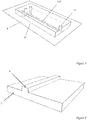
figure 1 est une vue de dessus d'un exemple de réseau de microcanaux, - les
figures 2 à 4 décrivent les dispositifs mis en œuvre à différentes étapes d'un exemple de procédé de fabrication de microcanaux : - la
figure 2 représente un exemple de moule micro-usiné, - la
figure 3 représente le moulage d'une couche d'élastomère sur le moule micro-usiné, - la
figure 4 représente la couche d'élastomère séparée du moule micro-usiné, - la
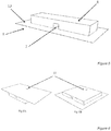
figure 5 représente un microcanal formé par la superposition de la couche d'élastomère et d'un substrat, - les
figures 6A et 6B présentent deux exemples d'un microcanal selon un mode de réalisation de l'invention, - la
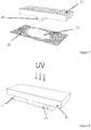
figure 7 représente un moule en élastomère au-dessus d'un substrat sur lequel est déposée une goutte de liquide photoréticulable, - la
figure 8 représente la superposition du moule en élastomère et du substrat sur lequel est déposée une goutte de liquide photoréticulable, et l'illumination UV destinée à produire la réticulation du liquide photoréticulable, - les
figures 9A et 9B représentent le microsystème obtenu après superposition du premier substrat et du matériau réticulé avec le second substrat, - la
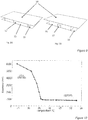
figure 10 représente une modification de l'épaisseur du film d'hydrogel en fonction de la température, - la
figure 11 est une illustration du principe de vannes créé par l'activation thermique de l'hydrogel : lafigure 11A est une vue en coupe du microsystème pour une température inférieure à 32°C, l'hydrogel est déplié et obstrue le microcanal, lafigure 11B est une vue en coupe du microsystème pour une température supérieure à 32°, l'hydrogel est replié et le microcanal est ouvert, - la
figure 12 montre l'évolution du débit (normalisé par un débit de référence Qf) le long d'un microcanal de 4 microns de haut, soumis à une différence de pression de 3bars. Chaque symbole correspond à des expériences réalisées dans les mêmes conditions, - la
figure 13 montre un exemple d'évolution de la résistance hydrodynamique normalisée d'un microcanal en fonction de la température dans un canal de 7 microns de haut, - la
figure 14 montre comment la réalisation d'une micropompe par activation thermique de l'hydrogel. - Les microcanaux concernés par la présente invention (dont un exemple est illustré
figure 1 ) sont réalisés par une étape de mise en forme d'un matériau. Par exemple, cette étape de mise en forme peut être réalisée par gravure, par micro-usinage de verre ou de silicium, par différentes techniques de moulage avec des polymères : thermoformage ou moulage à chaud, ablation de polymère, ou moulage de polymère. - Selon la technique utilisée les matériaux mis en œuvre peuvent être tout types de polymères, et par exemple des polymères tels que le polystyrène (PS), le polycarbonate (PC), le polyvinyl chloride (PVC), des Cyclic Olefin Copolymers (COC), le Poly(Metyl methacrylate) (PMMA), le thermoset Polyester (TPE), le Polyurethane Methacrylate (PUMA), ou encore des Acrylonitrile Butadiène Styrènes.
- Les matériaux peuvent également être choisis parmi les liquides ou colles photoréticulables ou photosensibles, par exemple la Norland Optical Adhesive (NOA).
- Une fois la mise en forme du matériau réalisée, le matériau est positionné sur une couche d'un substrat plat sur lequel une couche d'un polymère de type hydrogel est greffée de manière covalente. Le matériau moulé est positionné de façon à ce que le renfoncement, créé par le moulage, la gravure ou l'usinage, forme un canal microfluidique du côté de l'hydrogel.
- Le microcanal (7, 17) (
figures 5 et9 ) est ainsi formé à l'interface de deux couches de matériau, au moins un des deux matériaux étant un substrat (9, 14, 15, 16). Un volume du microcanal est contenu dans le renfoncement formé dans le matériau. - Le polymère de type hydrogel à greffer, utilisé dans le cadre de la présente invention et contenu dans le volume du microcanal, est un polymère insoluble dans l'eau et capable de constituer un gel avec un grand pouvoir absorbant en présence d'un liquide ou fluide. Ces polymères possèdent un haut degré de flexibilité. En effet, il est possible d'augmenter leur volume sous l'action d'un stimulus de type variation de température, de lumière, de pH, de champ électrique. Le polymère de type hydrogel à greffer est greffé de façon à pouvoir à s'expandre perpendiculairement à son plan de fixation, c'est-à-dire pouvoir gonfler verticalement. Les contraintes sur le polymère de type hydrogel sont donc perpendiculaires à la surface et ne risquent pas de provoquer des ruptures de l'attachement au support.
- Dans le cadre de l'invention, le polymère de type hydrogel est greffé avec des liaisons covalentes sur un support dans le microcanal.
- Selon un mode de réalisation de l'invention, le polymère de type hydrogel est greffé sur le support avant son insertion dans le microcanal, c'est-à-dire hors du microcanal.
- Selon un mode de réalisation de l'invention, le polymère de type hydrogel est greffé sur le support lorsque le support est déjà dans le microcanal.
- La présence du polymère greffé (hydrogel) dans les microcanaux a pour but de permettre, sous l'effet d'un des stimuli décrits, de fermer ou d'ouvrir lesdits microcanaux. C'est donc la couche de polymère greffé dans le microcanal qui joue le rôle de microvannes ou de micropompes au niveau du microcanal.
- Le polymère greffé sous forme de couche sur le substrat est simple à mettre en œuvre et ne nécessite pas de technique particulière. Notamment, il n'est pas nécessaire, comme cela est le cas dans l'art antérieur, de creuser le substrat au niveau des microcanaux pour y inclure le polymère de type hydrogel.
- Les microcanaux selon l'invention se différencient ainsi de ceux de l'art antérieur par le fait qu'ils comportent une couche d'hydrogel déposé sur le substrat en contact avec l'ouverture formant le canal.
- Les
figures 2 à 5 illustrent une premier mode de réalisation d'un microcanal selon l'invention. Un premier moule (5) est fabriqué par toute méthode connue : micro-usinage, photolithographie, ablation laser, micro-injection, etc. et possède une protrusion (6). - Un élastomère (8) est coulé sur ce moule (
figure 2 ), puis solidifié thermiquement, de telle sorte qu'un renfoncement (7) soit créé dans l'élastomère (8), correspondant à l'image inversée de la protrusion (6) (figure 3 ). - L'élastomère (8) est ensuite retiré du moule (5), comme illustré sur la
figure 4 , puis positionné au-dessus du substrat plat (9) sur lequel le polymère de type hydrogel (10) est greffé de manière covalente (figure 5 ). - La structure en élastomère (8) est ensuite collée au substrat (9) du côté de l'hydrogel (10), le renfoncement (7) formant ainsi un canal microfluidique dans lequel des fluides peuvent être amenés par des trous (11) percés soit sur le substrat (
figure 6A ) soit sur l'élastomère (figure 6B ). - La structure en élastomère peut être collée de manière réversible sur le substrat, ou de manière irréversible. Il est possible de superposer à ce système une autre couche d'élastomère dans laquelle on peut faire circuler un fluide chargé, servant d'électrode liquide lorsque l'on désire utiliser un champ électrique comme stimulus.
- Cette technique permet, si on désire utiliser un champ électrique comme stimulus, de superposer à ce système une autre couche d'élastomère dans laquelle on peut faire circuler un fluide chargé, servant d'électrode liquide.
- Les
figures 7 et 8 illustrent un deuxième mode de réalisation du procédé selon l'invention. Ce deuxième mode de réalisation utilise un moule, appelé timbre, fait dans un matériau élastomère (12) et comprenant un profil complémentaire (13) de celui du microcanal que l'on veut réaliser. Le moule est construit selon la méthode décrite précédemment. - Un premier substrat plat (14) en matériau solide est placé de manière parallèle à ce timbre (12). Un liquide photoréticulable ou photosensible (15) en quantité suffisante est déposé sur le substrat (14). Le timbre (12) est placé sur le substrat (14). Comme illustré sur la
figure 8 , en exerçant une pression sur le timbre (12), le liquide (15) occupe les espaces creux du timbre en élastomère. Le liquide est ensuite traité par irradiation ou par chauffage jusqu'à sa réticulation. Le timbre est retiré du système constitué du premier substrat (14) et du matériau réticulé (15). Ledit système est déposé sur un second substrat (16), second substrat sur lequel est greffé l'hydrogel. - Avec cette technique, le microcanal (17) peut être séparé du premier substrat (14) par une fine couche de matériau réticulé (15) comme montré sur la
figure 9B , ou peut être en contact avec le premier substrat (14) comme montré sur lafigure 9A . - Le matériau formant les microcanaux peut être fixé ou collé de manière réversible ou irréversible, sur le substrat, ce qui peut être avantageux lorsque de fortes pressions doivent être appliquées.
- La réalisation des microvannes ou micropompes intégrées aux microcanaux, et formées par le film d'hydrogel, nécessite au moins : une phase de synthèse d'un polymère, une étape de greffage du polymère. L'étape de greffage comportant une phase de modification chimique du polymère et une phase de modification des propriétés chimiques de surface du substrat.
- Pour la synthèse du polymère à greffer, qui peut se faire de différentes méthodes, de nombreux monomères peuvent être utilisés. Le choix du monomère, pour une application donnée, est conditionné par le type de stimulus qui sera utilisé pour actionner la microvanne ou la micropompe. Le polymère à greffer peut ainsi être choisi parmi ceux sensibles aux variations de température, de lumière, de champ électrique ou de pH.
- Si le stimulus est la variation de température, on pourra choisir de faire des polymères à température critique de dissolution inférieure (LCST pour Lower Critical Solution Temperature selon la terminologie anglaise) ou à température critique de dissolution supérieure (UCST pour Upper Critical Solution Temperature selon la terminologie anglaise), et par exemple le Poly N-isopropylacrylamide (PNIPAM),
- Si le stimulus est la variation de lumière on pourra utiliser des polymères du type de ceux sensibles à la température sur lesquels on aura greffé un groupement chromophore, par exemple un groupement azobenzène,
- Si le stimulus est la variation de pH on pourra utiliser des polyélectrolytes faibles, par exemple le Poly(acide acrylique) (PAA), le Poly(méthacrylate de diméthylamino éthyle)(PMADAME) ou encore des polyampholytes faibles, par exemple un PAA-co-PMADAME,
- Si le stimulus est la variation de champ électrique on pourra utiliser des polyélectrolytes par exemple le Poly(acrylamido methyl propane sulfonate) (PAMPS).
- Il peut être avantageux d'utiliser des copolymères, en particulier des copolymères possédant des motifs acide acrylique tels que ceux connus sous le nom de PAA, qui permettent la fonctionnalisation nécessaire à la formation de l'hydrogel et à son greffage sur la surface.
- La modification chimique des polymères peut être réalisée de plusieurs façons. Cette étape de modification est nécessaire pour pouvoir greffer les hydrogels à l'intérieur des systèmes microfluidiques. La modification chimique peut, par exemple, être une amidification au moyen d'une amine comportant un groupe vinylique. On obtient ainsi un polymère fonctionnalisé.
- Les modifications chimiques de la surface du substrat permettant le greffage de l'hydrogel sont réalisées par différentes méthodes. Le but de cette étape est de greffer le polymère fonctionnalisé sur une surface du microsystème modifiée en formant une monocouche auto assemblée (SAM) portant des groupements thiols sur laquelle le polymère fonctionnalisé, mélangé avec un réticulant, est déposé sur ladite surface modifiée.
- Lorsque le polymère fonctionnalisé est greffé sur le substrat, et hydraté, il est ainsi possible d'exploiter son augmentation de volume ou gonflement vertical dans un microcanal sous l'effet d'un stimulus. Un tel gonflement vertical de l'hydrogel peut avoir trois effets selon la géométrie du système et les conditions d'application du stimulus :
- il permet de modifier la résistance hydrodynamique du microcanal si celui-ci est plus grand que le gonflement maximal de l'hydrogel,
- il permet d'ouvrir et de fermer le microcanal de manière réversible si sa section est plus petite que la dimension maximale de l'hydrogel gonflé, ce qui crée un système de vannes,
- il permet d'ouvrir et de fermer le microcanal entraînant le déplacement du fluide à l'intérieur du microsystème, ce qui crée un système de pompage de très petite dimension.
- Le polymère fonctionnalisé utilisé dans le cadre de l'invention peut être déposé sur le substrat par dépôt mécanique tel que dépôt à la tournette, dépôt par immersion, dépôt par laminage, dépôt par pulvérisation, coulée de solvant et de particules (solvant casting), lixiviation, etc. Dans tous les cas, la couche d'hydrogel est ainsi formée sur le substrat par greffage avec liaison covalente.
- Le polymère fonctionnalisé est déposé sur toute la surface du substrat ou sur seulement une partie de la surface du substrat. La partie de la surface du substrat recouverte par l'hydrogel est comprise par exemple entre 1 nm2 et 1 mm2.
- Le polymère greffé anhydre a une épaisseur comprise par exemple entre 1 nanomètre et 10 microns. Le polymère greffé hydraté a une épaisseur comprise par exemple entre 10 nanomètres et 1 millimètre.
- Les microcanaux ont une longueur comprise par exemple entre 0,1 nanomètre et 5 millimètres, et de préférence entre 1 nanomètre et 1 millimètre.
- Les microcanaux ont une largeur comprise par exemple entre 0,1 nanomètre et 5 millimètre, et de préférence entre 1 nanomètre et 1 millimètre.
- Les microcanaux ont une hauteur comprise par exemple entre 0,1 nanomètre et 5 millimètre, et de préférence entre 1 nanomètre et 1 millimètre.
- Le substrat est, par exemple, un matériau massif tel que du verre, du silicium, un métal, un polymère, ou encore une combinaison de tous ces matériaux.
- Selon une variante, le substrat est recouvert d'un film d'or.
- Selon une autre variante, le substrat est transparent aux rayons infrarouges.
- Selon une variante, le substrat est choisi dans la famille des Acrylonitrile Butadiène Styrène.
- L'invention concerne également un système microfluidique (117) formé par, au moins, un microcanal selon l'invention.
- L'invention va maintenant être illustrée avec les exemples suivants non limitatifs.
- La réalisation des microvannes ou micropompes comprend: une phase de synthèse du polymère à greffer, une phase modification chimique du polymère à greffer et une phase de modification des propriétés chimiques de surface du substrat.
- Pour réaliser la synthèse du polymère de type hydrogel, un ou plusieurs monomères et un initiateur de réaction sont introduits dans une solution et une méthode de copolymérisation radicalaire est utilisée.
- Pour la synthèse d'un copolymère à base d'acide acrylique et de N-isopropylacrylamide (PAA-co-PNIPAM) on utilise un système d'amorçage réducteur-oxydant avec pour couple le persulfate d'ammonium et le métabisulfite de sodium : (NH4)2S2O8/Na2S2O5.
- Un copolymère PAA-co-PNIPAM à 90% de motif NIPAM est obtenu après mélange de 90% de NIPAM et 10% de AA.
- On introduit ensuite des solutions de (NH4)2S2O8 et de Na2S2O5 et on active la polymérisation en présence du système redox.
- Après dialyse et lyophilisation on obtient le polymère sous forme solide.
- La modification chimique du polymère à greffer peut être une amidification, c'est à dire une réaction entre une amine possédant un groupe vinylique et une partie des motifs acide acrylique.
- Dans le cas d'un PAA-co-PNIPAM à 10% de motifs AA, on peut modifier une partie des groupements acides acryliques en leur greffant un allylamine.
- Pour cela on introduit une quantité stœchiométrique d'allylamine par rapport à la quantité de motifs acide acrylique que l'on veut modifier.
- On mélange le PAA-co-PNIPAM, l'allylamine ainsi que le chlorhydrate de 1-(3-diméthylaminopropyl)-3-éthyl carbodiimide noté EDC.
- En présence d'EDC, les fonctions carboxyliques du squelette du PAA permettent le greffage des fonctions amines sur ces dernières.
- Une fois la synthèse terminée, on dialyse et lyophilise. On obtient ainsi le polymère fonctionnalisé sous forme solide.
- Sont décrits ici deux exemples de méthode permettant de greffer l'hydrogel sur une surface du microsystème modifiée en formant une monocouche auto assemblée (SAM) permettant de greffer des groupements thiols sur laquelle le polymère fonctionnalisé, mélangé avec un réticulant, est déposé .
- Un microcanal est fabriqué selon les méthodes décrites sur les
figures 2 à 9 . Pour modifier la surface, sur laquelle le polymère de type hydrogel va être greffé, on soumet ladite surface à une solution contenant un composé thiolé et un solvant. On rince ensuite cette surface avec ce même solvant. - Par exemple, si la surface est recouverte d'or la solution peut être un mélange de dithiolerytrhitol à 0,3 millimolaire dans du chloroforme et le solvant utilisé dans ce cas pour rincer la surface est du chloroforme.
- Afin de réaliser le greffage de l'hydrogel sur le substrat, on le solubilise dans un mélange de solvant et de réticulant et on introduit cette solution dans le microsystème. Après réticulation, le système est rincé avec ce même solvant.
- Dans cet exemple, l'hydrogel est préalablement greffé sur une surface d'un substrat et Un microcanal est ensuite fabriqué à partir de ce substrat selon les méthodes décrites sur les
figures 2 à 9 . - Pour cela il est nécessaire de tout d'abord modifier la surface puis de greffer l'hydrogel.
- Cette première étape est réalisée par silanisation, dans le cas d'un substrat de verre, par voie liquide en immergeant le verre en question dans un mélange à 3% de Mercaptopropyltrimethoxysilane dans du toluène.
- L'étape suivante est réalisée par dépôt mécanique. Par exemple, le polymère fonctionnalisé initialement sous forme solide est solubilisé dans un mélange de solvant, par exemple du butanol, et d'un thiol, par exemple du dithiolerythritol. La solution ainsi élaborée est déposée à la tournette sur le verre silanisé.
- Comme cela a déjà été expliqué, plusieurs types de monomères et de réticulant, dans différentes proportions peuvent être choisis selon le stimulus choisi.
- Si le stimulus est la température, il s'agit de copolymères de motifs acide acrylique (AA) et N-isopropylacrylamide(NIPAM) qui subit une transition réversible autour de sa LCST typiquement de l'ordre de 32°C. A une température inférieure ce copolymère est hydrophile et déplié en solution aqueuse alors qu'à une température supérieure il devient hydrophobe et se replie sur lui-même.
- La synthèse du copolymère est réalisée selon une des deux méthodes décrites précédemment. On obtient un copolymère statistique dans lequel les unités monomères sont réparties de manière aléatoire dans la chaîne.
- La fonction NIPAM est celle qui est responsable de l'activation par la température, la fonction AA sert elle, après modification, au greffage du polymère sur la surface. Dans ce cas le polymère utilisé est un P(AA-co-NIPAM) à 10% de motif AA.
- La modification du copolymère est également réalisée selon la méthode décrite précédemment. La modification de la lame de verre que l'on utilise comme substrat est réalisée par silanisation selon la méthode décrite précédemment
- Une fois cette surface traitée, un mélange de PAA-co-PNIPAM, butanol, dithiol, est déposé à la tournette sur celle-ci.
- L'épaisseur du film peut être caractérisée en fonction de la température par ellipsométrie. Dans cet exemple, l'épaisseur du film d'hydrogel décroît lorsque la température croit comme montré sur la
figure 10 . - Les microcanaux sont réalisés dans un matériau dur, appelé NOA (Norland Optical Adhesive), selon l'une des méthodes décrites précédemment. On obtient un système possédant trois parois en NOA et une paroi en verre traitée avec l'hydrogel.
- Dans cet exemple, la hauteur des microcanaux peut être comprise entre 1 et 10 microns, et de préférence entre 4 et 7 microns.
- La variation de température est obtenue de toute manière connue. Ainsi, pour chauffer on peut illuminer le polymère par un rayonnement électromagnétique à des fréquences correspondant à des pics d'absorption ou encore utiliser une résistance parcourue par un courant électrique. Pour refroidir il est possible d'utiliser par exemple un module à effet Peltier.
- La
figure 11 est une illustration du principe mis en œuvre dans une microvanne lors de l'activation thermique de l'hydrogel. Si la pression dans le microcanal est maintenue constante, les variations de volume de l'hydrogel induisent un changement de la résistance du microcanal et donc du débit du fluide qui y circule. Il est à noter que la mesure du débit dans le microcanal permet de déduire l'épaisseur de l'hydrogel. Ainsi lafigure 11A illustre un microcanal fermé, à une température inférieure à 32°C, et lafigure 11B un microcanal ouvert, à une température supérieure à 32°C. - La
figure 12 montre l'évolution du débit Q (normalisé par un débit de référence Qf) le long d'un microcanal de 4 microns de haut, soumis à une différence de pression de 0,3 MP. Afin de vérifier la répétabilité des gonflements on a effectué plusieurs cycles de mesure, chacun étant représenté par un symbole. - La
figure 13 est une courbe montrant l'évolution de la résistance hydrodynamique du système en fonction de la température dans un microcanal de 7 microns de haut. Avec une telle hauteur utilisée le microcanal n'est pas totalement fermé quand l'hydrogel est à son maximum de gonflement. - Sur la
figure 14 la courbe A montre les cycles de température entre 29°C et 34°C et la courbe B l'évolution du débit correspondante. On peut constater que l'écoulement du fluide se fait avec un léger retard par rapport à la variation de température. - Ainsi, le dispositif selon l'invention permet de réaliser des systèmes de pompage en effectuant des cycles d'élévation et diminution de la température.
- Il résulte de ce qui vient d'être décrit, qu'il est possible d'utiliser une large gamme de matériaux: élastomère, verre, silicium, polymère, etc . Il est également possible de réaliser des dispositifs adaptés à de larges gammes de pression, d'avoir des propriétés de surfaces adaptées aux applications visées, de choisir le stimulus bien adapté à chaque application considérée.
- Il est possible de choisir comme substrat un matériau bon conducteur de la chaleur si le stimulus concerné est la température.
- De même, on peut choisir de déposer des électrodes liquides ou solides, par exemple sous forme de films minces sur les deux surfaces qui se font face à l'intérieur du microsystème.
- De même, on peut utiliser un matériau transparent aux longueurs d'ondes permettant d'activer le polymère dans le cas ou le stimulus est la lumière.
- Le traitement du substrat avec l'hydrogel peut être fait une fois le microsystème fermé ou être fait avant et être intégré ultérieurement.
- La portée de la présente invention ne se limite pas aux détails donnés ci-dessus et permet des modes de réalisation sous de nombreuses autres formes spécifiques sans s'éloigner du domaine d'application de l'invention. Par conséquent, les présents modes de réalisation doivent être considérés à titre d'illustration, et peuvent être modifiés sans toutefois sortir de la portée définie par les revendications.
Claims (9)
- Procédé de fabrication d'un microcanal, caractérisé en ce qu'il comprend au moins :- une étape de fixation par liaison covalente d'un polymère de type hydrogel sur une face d'un substrat, le polymère de type hydrogel étant susceptible de subir des variations de volume sous l'action d'un stimulus extérieur ;- une étape de formation dudit microcanal à l'interface de deux couches de matériau, au moins un des deux matériaux étant le substrat, de manière que le polymère est disposé dans le volume dudit microcanal ;et en ce que :- l'étape de fixation du polymère est réalisée avant l'étape de formation du microcanal ;- ladite face du substrat est plate ;- lesdites variations de volume étant réalisées perpendiculairement à ladite face du substrat ;- le polymère modifiant la résistance hydrodynamique du microcanal de manière réversible.
- Procédé selon la revendication 1, dans lequel l'étape de greffage comprend deux phases, une phase de modification chimique du polymère de type hydrogel et une phase de modification des propriétés chimiques de surface du substrat.
- Procédé selon une des revendications 1 ou 2, dans lequel l'étape de greffage est précédée d'une phase de synthèse du polymère de type hydrogel.
- Procédé selon la revendication 3, dans lequel le polymère de type hydrogel est synthétisé par réticulation entre chaines de polymère fonctionnalisées, la synthèse des chaînes de polymère étant faite par copolymérisation radicalaire.
- Procédé selon une des revendications 2 à 5, dans lequel la modification chimique des polymères est une amidification au moyen d'une amine comportant au moins un groupe vinylique
- Microcanal (7, 17) formé à l'interface de deux couches de matériau à l'aide du procédé selon l'une quelconque des revendications précédentes, au moins un des deux matériaux étant un substrat (9, 14, 15, 16), un film (10) de polymère étant fixé sur la couche de substrat dans un volume du microcanal (7, 17), ledit film de polymère étant formé d'un matériau de type hydrogel susceptible de subir des variations de volume sous l'action d'un stimulus extérieur,
caractérisé en ce que :- le substrat du film est plat ;- le film est greffé sur le substrat plat par liaison covalente ;- le film est adapté pour modifier de manière réversible la résistance hydrodynamique du microcanal en gonflant perpendiculairement à son substrat ;- ledit microcanal est configuré pour être ouvert et fermé de manière réversible par les variations de volume du film perpendiculairement à son substrat. - Microcanal selon la revendication 6, dans lequel le polymère de type hydrogel est choisi parmi ceux sensibles aux variations de température, de lumière, de champ électrique ou de pH.
- Microcanal selon l'une quelconque des revendications 6 ou 7, caractérisé en ce qu'il est configuré pour déplacer un fluide en ouvrant en fermant par biais des variations de volume du film.
- Système microfluidique, caractérisé en ce qu'il comporte au moins un microcanal selon une quelconque des revendications 6 à 8.
Applications Claiming Priority (2)
| Application Number | Priority Date | Filing Date | Title |
|---|---|---|---|
| FR1251722A FR2987282B1 (fr) | 2012-02-24 | 2012-02-24 | Microcanal avec dispositif d'ouverture et/ou fermeture et/ou pompage |
| PCT/EP2013/053612 WO2013124448A1 (fr) | 2012-02-24 | 2013-02-22 | Microcanal avec dispositif d'ouverture et/ou fermeture et/ou pompage |
Publications (2)
| Publication Number | Publication Date |
|---|---|
| EP2817088A1 EP2817088A1 (fr) | 2014-12-31 |
| EP2817088B1 true EP2817088B1 (fr) | 2020-07-01 |
Family
ID=47827170
Family Applications (1)
| Application Number | Title | Priority Date | Filing Date |
|---|---|---|---|
| EP13707596.6A Active EP2817088B1 (fr) | 2012-02-24 | 2013-02-22 | Microcanal avec dispositif d'ouverture et/ou fermeture et/ou pompage |
Country Status (8)
| Country | Link |
|---|---|
| US (1) | US9512935B2 (fr) |
| EP (1) | EP2817088B1 (fr) |
| JP (1) | JP6148259B2 (fr) |
| KR (1) | KR20140134296A (fr) |
| CN (1) | CN104349836A (fr) |
| ES (1) | ES2818539T3 (fr) |
| FR (1) | FR2987282B1 (fr) |
| WO (1) | WO2013124448A1 (fr) |
Families Citing this family (14)
| Publication number | Priority date | Publication date | Assignee | Title |
|---|---|---|---|---|
| CA2263890C (fr) | 1996-08-23 | 2013-05-14 | Ludwig Institute For Cancer Research | Facteur d recombinant de croissance des cellules endotheliales vasculaires (vegf-d) |
| EP3177920B1 (fr) * | 2014-08-05 | 2021-03-31 | Sanwa Biotech Ltd. | Système de diagnostic sur site et procédé correspondant |
| GB2533386B (en) * | 2014-12-18 | 2019-09-11 | Smiths Detection Watford Ltd | A detection apparatus with pneumatic interface |
| KR101597936B1 (ko) * | 2015-04-16 | 2016-02-25 | 고려대학교 산학협력단 | 이온 채널 소자 |
| CN105388126A (zh) * | 2015-10-16 | 2016-03-09 | 北京农业信息技术研究中心 | 一种基于相位变化检测pH值的传感装置 |
| KR101868221B1 (ko) * | 2016-03-14 | 2018-06-15 | 고려대학교 산학협력단 | 이온 채널 압력 센서 및 이의 제조방법 |
| US11148389B2 (en) | 2016-03-20 | 2021-10-19 | Massachusetts Institute Of Technology | Hydrogel-elastomer hybrids |
| CN106903681A (zh) * | 2017-03-28 | 2017-06-30 | 徐州乐泰机电科技有限公司 | 一种软体机器人 |
| JP7071641B2 (ja) * | 2018-10-18 | 2022-05-19 | 日本電信電話株式会社 | 積層体、積層体の製造方法および形状制御デバイス |
| ES2887874B2 (es) * | 2020-06-23 | 2022-11-18 | Consejo Superior Investigacion | Valvula microfluidica, procedimiento de fabricacion y usos de la misma |
| KR20220126586A (ko) | 2021-03-09 | 2022-09-16 | 삼성전자주식회사 | 잉크젯 프린트 헤드 |
| US12529637B2 (en) * | 2023-02-21 | 2026-01-20 | Halliburton Energy Services, Inc. | Measurement of water chemistry by altering the resonant frequency of a vibrating element with hydrophilic hydrogels |
| WO2024218855A1 (fr) * | 2023-04-18 | 2024-10-24 | 日本電信電話株式会社 | Procédé de production de stratifié et stratifié |
| JPWO2024218854A1 (fr) * | 2023-04-18 | 2024-10-24 |
Citations (1)
| Publication number | Priority date | Publication date | Assignee | Title |
|---|---|---|---|---|
| US20070280858A1 (en) * | 2006-05-30 | 2007-12-06 | Fuji Xerox Co., Ltd. | Microchannel device |
Family Cites Families (15)
| Publication number | Priority date | Publication date | Assignee | Title |
|---|---|---|---|---|
| NZ533466A (en) | 1999-06-28 | 2005-10-28 | California Inst Of Techn | Microfabricated elastomeric valve and pump systems |
| AU6117700A (en) * | 1999-07-23 | 2001-02-13 | Board Of Trustees Of The University Of Illinois, The | Microfabricated devices and method of manufacturing the same |
| JP2002066999A (ja) * | 2000-08-30 | 2002-03-05 | Kawamura Inst Of Chem Res | 微小バルブ機構及びその製造方法 |
| US6626417B2 (en) * | 2001-02-23 | 2003-09-30 | Becton, Dickinson And Company | Microfluidic valve and microactuator for a microvalve |
| US7988685B2 (en) | 2001-11-01 | 2011-08-02 | Regents Of The University Of Minnesota | Hydrogel compositions, devices, and microscale components |
| DE10157317A1 (de) * | 2001-11-23 | 2003-06-05 | Gesim Ges Fuer Silizium Mikros | Grundelement eines Mikrofluidik-Prozessors |
| AU2003285849A1 (en) * | 2002-03-20 | 2004-03-29 | Advanced Sensor Technologies, Inc. | Personal monitor to detect exposure to toxic agents |
| CN1784605B (zh) * | 2003-10-15 | 2011-11-23 | 松下电器产业株式会社 | 毛细管芯片中流体的流通方法、使用该方法的流通控制装置 |
| DE102004062893A1 (de) * | 2004-12-20 | 2006-06-29 | Technische Universität Dresden | Elektronisch steuerbare Mikropumpe auf Hydrogelbasis |
| US20070196820A1 (en) * | 2005-04-05 | 2007-08-23 | Ravi Kapur | Devices and methods for enrichment and alteration of cells and other particles |
| JP2007170469A (ja) * | 2005-12-20 | 2007-07-05 | Kawamura Inst Of Chem Res | 温度応答性バルブおよびその製造方法 |
| DE102006051535A1 (de) * | 2006-10-27 | 2008-12-18 | Andreas Dr. Richter | Automatischer Mikrofluidik-Prozessor |
| EP1977687A1 (fr) * | 2007-04-05 | 2008-10-08 | Koninklijke Philips Electronics N.V. | Dispositif à base d'hydrogel pour détecter l'état de l'environnement |
| JP5513370B2 (ja) * | 2007-04-20 | 2014-06-04 | ベクトン・ディキンソン・アンド・カンパニー | ヒドロゲル組成物 |
| WO2011075575A1 (fr) * | 2009-12-17 | 2011-06-23 | Bayer Healthcare Llc | Systèmes, dispositifs et procédés transdermiques pour l'analyse optique d'une substance à analyser |
-
2012
- 2012-02-24 FR FR1251722A patent/FR2987282B1/fr active Active
-
2013
- 2013-02-22 WO PCT/EP2013/053612 patent/WO2013124448A1/fr not_active Ceased
- 2013-02-22 JP JP2014558130A patent/JP6148259B2/ja active Active
- 2013-02-22 KR KR1020147026339A patent/KR20140134296A/ko not_active Ceased
- 2013-02-22 US US14/376,432 patent/US9512935B2/en active Active
- 2013-02-22 CN CN201380021707.4A patent/CN104349836A/zh active Pending
- 2013-02-22 ES ES13707596T patent/ES2818539T3/es active Active
- 2013-02-22 EP EP13707596.6A patent/EP2817088B1/fr active Active
Patent Citations (1)
| Publication number | Priority date | Publication date | Assignee | Title |
|---|---|---|---|---|
| US20070280858A1 (en) * | 2006-05-30 | 2007-12-06 | Fuji Xerox Co., Ltd. | Microchannel device |
Also Published As
| Publication number | Publication date |
|---|---|
| WO2013124448A1 (fr) | 2013-08-29 |
| FR2987282B1 (fr) | 2017-12-29 |
| JP6148259B2 (ja) | 2017-06-14 |
| US20140373952A1 (en) | 2014-12-25 |
| KR20140134296A (ko) | 2014-11-21 |
| CN104349836A (zh) | 2015-02-11 |
| US9512935B2 (en) | 2016-12-06 |
| EP2817088A1 (fr) | 2014-12-31 |
| JP2015511181A (ja) | 2015-04-16 |
| ES2818539T3 (es) | 2021-04-13 |
| FR2987282A1 (fr) | 2013-08-30 |
Similar Documents
| Publication | Publication Date | Title |
|---|---|---|
| EP2817088A1 (fr) | Microcanal avec dispositif d'ouverture et/ou fermeture et/ou pompage | |
| Trantidou et al. | Hydrophilic surface modification of PDMS for droplet microfluidics using a simple, quick, and robust method via PVA deposition | |
| Kuckling | Responsive hydrogel layers—from synthesis to applications | |
| US20080138248A1 (en) | Method for improving the bonding properties of microstructured substrates, and devices prepared with this method | |
| US8715446B2 (en) | Latent solvent-based microfluidic apparatus, methods, and applications | |
| WO2008009803A2 (fr) | Fabrication de dispositifs microfluidiques polymeriques par impression photo- et/ou thermo-assistee | |
| Fatona et al. | One-step in-mould modification of PDMS surfaces and its application in the fabrication of self-driven microfluidic channels | |
| KR20070119624A (ko) | 액정 디스플레이에서 사용되는 낮은 표면 에너지 고분자물질 | |
| MX2010013204A (es) | Estructura de hoja de microfluido para la medicion de fluidos. | |
| FR2846906A1 (fr) | Procede de realisation d'un composant comportant un micro-joint et composant realise par ce procede | |
| KR100961850B1 (ko) | 친수성 필름을 이용한 무동력 미세 유체 칩 | |
| CN1902293A (zh) | 层压微流体结构与制造方法 | |
| Roy et al. | High performance of cyclic olefin copolymer-based capillary electrophoretic chips | |
| Huyen et al. | Flexible capillary microfluidic devices based on surface-energy modified polydimethylsiloxane and polymethylmethacrylate with room-temperature chemical bonding | |
| WO2004112961A1 (fr) | Procede de collage de substrats micro-structures | |
| Li et al. | Autonomous capillary microfluidic devices with constant flow rate and temperature-controlled valving | |
| Kuroki et al. | Tunable ultrathin membranes with nonvolatile pore shape memory | |
| Gu et al. | A hybrid microfluidic chip with electrowetting functionality using ultraviolet (UV)-curable polymer | |
| Beh et al. | PDMS–glass bonding using grafted polymeric adhesive–alternative process flow for compatibility with patterned biological molecules | |
| JP2005114414A (ja) | フローセル | |
| Banuprasad et al. | Thermally programmable dynamic capillarity in nanofluidic channels grafted with smart elastomeric layers | |
| Samuel et al. | Tailormade microfluidic devices through photochemical surface modification | |
| Kim et al. | Fabrication of triple-parted stomata-inspired membrane with stimulus-responsive functions | |
| FR3087763A1 (fr) | Puce microfluidique reversible | |
| KR20130069304A (ko) | 미세 유체 소자 및 그 제조방법 |
Legal Events
| Date | Code | Title | Description |
|---|---|---|---|
| PUAI | Public reference made under article 153(3) epc to a published international application that has entered the european phase |
Free format text: ORIGINAL CODE: 0009012 |
|
| 17P | Request for examination filed |
Effective date: 20140818 |
|
| AK | Designated contracting states |
Kind code of ref document: A1 Designated state(s): AL AT BE BG CH CY CZ DE DK EE ES FI FR GB GR HR HU IE IS IT LI LT LU LV MC MK MT NL NO PL PT RO RS SE SI SK SM TR |
|
| AX | Request for extension of the european patent |
Extension state: BA ME |
|
| DAX | Request for extension of the european patent (deleted) | ||
| STAA | Information on the status of an ep patent application or granted ep patent |
Free format text: STATUS: EXAMINATION IS IN PROGRESS |
|
| 17Q | First examination report despatched |
Effective date: 20170512 |
|
| RAP1 | Party data changed (applicant data changed or rights of an application transferred) |
Owner name: ECOLE SUPERIEURE DE PHYSIQUE ET DE CHIMIE INDUSTRI Owner name: CENTRE NATIONAL DE LA RECHERCHE SCIENTIFIQUE - CNR |
|
| GRAP | Despatch of communication of intention to grant a patent |
Free format text: ORIGINAL CODE: EPIDOSNIGR1 |
|
| STAA | Information on the status of an ep patent application or granted ep patent |
Free format text: STATUS: GRANT OF PATENT IS INTENDED |
|
| INTG | Intention to grant announced |
Effective date: 20200409 |
|
| GRAS | Grant fee paid |
Free format text: ORIGINAL CODE: EPIDOSNIGR3 |
|
| GRAA | (expected) grant |
Free format text: ORIGINAL CODE: 0009210 |
|
| STAA | Information on the status of an ep patent application or granted ep patent |
Free format text: STATUS: THE PATENT HAS BEEN GRANTED |
|
| AK | Designated contracting states |
Kind code of ref document: B1 Designated state(s): AL AT BE BG CH CY CZ DE DK EE ES FI FR GB GR HR HU IE IS IT LI LT LU LV MC MK MT NL NO PL PT RO RS SE SI SK SM TR |
|
| REG | Reference to a national code |
Ref country code: AT Ref legal event code: REF Ref document number: 1285627 Country of ref document: AT Kind code of ref document: T Effective date: 20200715 Ref country code: CH Ref legal event code: EP |
|
| REG | Reference to a national code |
Ref country code: DE Ref legal event code: R096 Ref document number: 602013070300 Country of ref document: DE |
|
| REG | Reference to a national code |
Ref country code: IE Ref legal event code: FG4D Free format text: LANGUAGE OF EP DOCUMENT: FRENCH |
|
| REG | Reference to a national code |
Ref country code: DK Ref legal event code: T3 Effective date: 20200930 |
|
| REG | Reference to a national code |
Ref country code: NL Ref legal event code: FP |
|
| REG | Reference to a national code |
Ref country code: SE Ref legal event code: TRGR |
|
| REG | Reference to a national code |
Ref country code: LT Ref legal event code: MG4D |
|
| PG25 | Lapsed in a contracting state [announced via postgrant information from national office to epo] |
Ref country code: BG Free format text: LAPSE BECAUSE OF FAILURE TO SUBMIT A TRANSLATION OF THE DESCRIPTION OR TO PAY THE FEE WITHIN THE PRESCRIBED TIME-LIMIT Effective date: 20201001 |
|
| REG | Reference to a national code |
Ref country code: AT Ref legal event code: MK05 Ref document number: 1285627 Country of ref document: AT Kind code of ref document: T Effective date: 20200701 |
|
| PG25 | Lapsed in a contracting state [announced via postgrant information from national office to epo] |
Ref country code: FI Free format text: LAPSE BECAUSE OF FAILURE TO SUBMIT A TRANSLATION OF THE DESCRIPTION OR TO PAY THE FEE WITHIN THE PRESCRIBED TIME-LIMIT Effective date: 20200701 Ref country code: GR Free format text: LAPSE BECAUSE OF FAILURE TO SUBMIT A TRANSLATION OF THE DESCRIPTION OR TO PAY THE FEE WITHIN THE PRESCRIBED TIME-LIMIT Effective date: 20201002 Ref country code: NO Free format text: LAPSE BECAUSE OF FAILURE TO SUBMIT A TRANSLATION OF THE DESCRIPTION OR TO PAY THE FEE WITHIN THE PRESCRIBED TIME-LIMIT Effective date: 20201001 Ref country code: PT Free format text: LAPSE BECAUSE OF FAILURE TO SUBMIT A TRANSLATION OF THE DESCRIPTION OR TO PAY THE FEE WITHIN THE PRESCRIBED TIME-LIMIT Effective date: 20201102 Ref country code: CZ Free format text: LAPSE BECAUSE OF FAILURE TO SUBMIT A TRANSLATION OF THE DESCRIPTION OR TO PAY THE FEE WITHIN THE PRESCRIBED TIME-LIMIT Effective date: 20200701 Ref country code: HR Free format text: LAPSE BECAUSE OF FAILURE TO SUBMIT A TRANSLATION OF THE DESCRIPTION OR TO PAY THE FEE WITHIN THE PRESCRIBED TIME-LIMIT Effective date: 20200701 Ref country code: AT Free format text: LAPSE BECAUSE OF FAILURE TO SUBMIT A TRANSLATION OF THE DESCRIPTION OR TO PAY THE FEE WITHIN THE PRESCRIBED TIME-LIMIT Effective date: 20200701 Ref country code: LT Free format text: LAPSE BECAUSE OF FAILURE TO SUBMIT A TRANSLATION OF THE DESCRIPTION OR TO PAY THE FEE WITHIN THE PRESCRIBED TIME-LIMIT Effective date: 20200701 |
|
| PG25 | Lapsed in a contracting state [announced via postgrant information from national office to epo] |
Ref country code: IS Free format text: LAPSE BECAUSE OF FAILURE TO SUBMIT A TRANSLATION OF THE DESCRIPTION OR TO PAY THE FEE WITHIN THE PRESCRIBED TIME-LIMIT Effective date: 20201101 Ref country code: LV Free format text: LAPSE BECAUSE OF FAILURE TO SUBMIT A TRANSLATION OF THE DESCRIPTION OR TO PAY THE FEE WITHIN THE PRESCRIBED TIME-LIMIT Effective date: 20200701 Ref country code: PL Free format text: LAPSE BECAUSE OF FAILURE TO SUBMIT A TRANSLATION OF THE DESCRIPTION OR TO PAY THE FEE WITHIN THE PRESCRIBED TIME-LIMIT Effective date: 20200701 Ref country code: RS Free format text: LAPSE BECAUSE OF FAILURE TO SUBMIT A TRANSLATION OF THE DESCRIPTION OR TO PAY THE FEE WITHIN THE PRESCRIBED TIME-LIMIT Effective date: 20200701 |
|
| REG | Reference to a national code |
Ref country code: DE Ref legal event code: R097 Ref document number: 602013070300 Country of ref document: DE |
|
| REG | Reference to a national code |
Ref country code: ES Ref legal event code: FG2A Ref document number: 2818539 Country of ref document: ES Kind code of ref document: T3 Effective date: 20210413 |
|
| PG25 | Lapsed in a contracting state [announced via postgrant information from national office to epo] |
Ref country code: EE Free format text: LAPSE BECAUSE OF FAILURE TO SUBMIT A TRANSLATION OF THE DESCRIPTION OR TO PAY THE FEE WITHIN THE PRESCRIBED TIME-LIMIT Effective date: 20200701 Ref country code: SM Free format text: LAPSE BECAUSE OF FAILURE TO SUBMIT A TRANSLATION OF THE DESCRIPTION OR TO PAY THE FEE WITHIN THE PRESCRIBED TIME-LIMIT Effective date: 20200701 Ref country code: RO Free format text: LAPSE BECAUSE OF FAILURE TO SUBMIT A TRANSLATION OF THE DESCRIPTION OR TO PAY THE FEE WITHIN THE PRESCRIBED TIME-LIMIT Effective date: 20200701 |
|
| PLBE | No opposition filed within time limit |
Free format text: ORIGINAL CODE: 0009261 |
|
| STAA | Information on the status of an ep patent application or granted ep patent |
Free format text: STATUS: NO OPPOSITION FILED WITHIN TIME LIMIT |
|
| PG25 | Lapsed in a contracting state [announced via postgrant information from national office to epo] |
Ref country code: AL Free format text: LAPSE BECAUSE OF FAILURE TO SUBMIT A TRANSLATION OF THE DESCRIPTION OR TO PAY THE FEE WITHIN THE PRESCRIBED TIME-LIMIT Effective date: 20200701 |
|
| 26N | No opposition filed |
Effective date: 20210406 |
|
| PG25 | Lapsed in a contracting state [announced via postgrant information from national office to epo] |
Ref country code: SK Free format text: LAPSE BECAUSE OF FAILURE TO SUBMIT A TRANSLATION OF THE DESCRIPTION OR TO PAY THE FEE WITHIN THE PRESCRIBED TIME-LIMIT Effective date: 20200701 |
|
| PG25 | Lapsed in a contracting state [announced via postgrant information from national office to epo] |
Ref country code: SI Free format text: LAPSE BECAUSE OF FAILURE TO SUBMIT A TRANSLATION OF THE DESCRIPTION OR TO PAY THE FEE WITHIN THE PRESCRIBED TIME-LIMIT Effective date: 20200701 |
|
| PG25 | Lapsed in a contracting state [announced via postgrant information from national office to epo] |
Ref country code: MC Free format text: LAPSE BECAUSE OF FAILURE TO SUBMIT A TRANSLATION OF THE DESCRIPTION OR TO PAY THE FEE WITHIN THE PRESCRIBED TIME-LIMIT Effective date: 20200701 |
|
| PG25 | Lapsed in a contracting state [announced via postgrant information from national office to epo] |
Ref country code: LU Free format text: LAPSE BECAUSE OF NON-PAYMENT OF DUE FEES Effective date: 20210222 |
|
| REG | Reference to a national code |
Ref country code: DE Ref legal event code: R079 Ref document number: 602013070300 Country of ref document: DE Free format text: PREVIOUS MAIN CLASS: B01F0005060000 Ipc: B01F0025400000 |
|
| PG25 | Lapsed in a contracting state [announced via postgrant information from national office to epo] |
Ref country code: HU Free format text: LAPSE BECAUSE OF FAILURE TO SUBMIT A TRANSLATION OF THE DESCRIPTION OR TO PAY THE FEE WITHIN THE PRESCRIBED TIME-LIMIT; INVALID AB INITIO Effective date: 20130222 |
|
| PG25 | Lapsed in a contracting state [announced via postgrant information from national office to epo] |
Ref country code: CY Free format text: LAPSE BECAUSE OF FAILURE TO SUBMIT A TRANSLATION OF THE DESCRIPTION OR TO PAY THE FEE WITHIN THE PRESCRIBED TIME-LIMIT Effective date: 20200701 |
|
| PG25 | Lapsed in a contracting state [announced via postgrant information from national office to epo] |
Ref country code: MK Free format text: LAPSE BECAUSE OF FAILURE TO SUBMIT A TRANSLATION OF THE DESCRIPTION OR TO PAY THE FEE WITHIN THE PRESCRIBED TIME-LIMIT Effective date: 20200701 |
|
| PG25 | Lapsed in a contracting state [announced via postgrant information from national office to epo] |
Ref country code: MT Free format text: LAPSE BECAUSE OF FAILURE TO SUBMIT A TRANSLATION OF THE DESCRIPTION OR TO PAY THE FEE WITHIN THE PRESCRIBED TIME-LIMIT Effective date: 20200701 |
|
| PGFP | Annual fee paid to national office [announced via postgrant information from national office to epo] |
Ref country code: NL Payment date: 20250218 Year of fee payment: 13 |
|
| PGFP | Annual fee paid to national office [announced via postgrant information from national office to epo] |
Ref country code: DK Payment date: 20250224 Year of fee payment: 13 |
|
| PGFP | Annual fee paid to national office [announced via postgrant information from national office to epo] |
Ref country code: IE Payment date: 20250220 Year of fee payment: 13 |
|
| PGFP | Annual fee paid to national office [announced via postgrant information from national office to epo] |
Ref country code: BE Payment date: 20250218 Year of fee payment: 13 |
|
| PGFP | Annual fee paid to national office [announced via postgrant information from national office to epo] |
Ref country code: ES Payment date: 20250331 Year of fee payment: 13 |
|
| PG25 | Lapsed in a contracting state [announced via postgrant information from national office to epo] |
Ref country code: TR Free format text: LAPSE BECAUSE OF FAILURE TO SUBMIT A TRANSLATION OF THE DESCRIPTION OR TO PAY THE FEE WITHIN THE PRESCRIBED TIME-LIMIT Effective date: 20200701 |
|
| REG | Reference to a national code |
Ref country code: CH Ref legal event code: U11 Free format text: ST27 STATUS EVENT CODE: U-0-0-U10-U11 (AS PROVIDED BY THE NATIONAL OFFICE) Effective date: 20260301 |
|
| PGFP | Annual fee paid to national office [announced via postgrant information from national office to epo] |
Ref country code: SE Payment date: 20260223 Year of fee payment: 14 |
|
| PGFP | Annual fee paid to national office [announced via postgrant information from national office to epo] |
Ref country code: GB Payment date: 20260223 Year of fee payment: 14 |
|
| PGFP | Annual fee paid to national office [announced via postgrant information from national office to epo] |
Ref country code: DE Payment date: 20260224 Year of fee payment: 14 |
|
| PGFP | Annual fee paid to national office [announced via postgrant information from national office to epo] |
Ref country code: IT Payment date: 20260224 Year of fee payment: 14 |
|
| PGFP | Annual fee paid to national office [announced via postgrant information from national office to epo] |
Ref country code: FR Payment date: 20260223 Year of fee payment: 14 |
|
| PGFP | Annual fee paid to national office [announced via postgrant information from national office to epo] |
Ref country code: CH Payment date: 20260301 Year of fee payment: 14 |