EP2817065B1 - Medical apparatus - Google Patents
Medical apparatus Download PDFInfo
- Publication number
- EP2817065B1 EP2817065B1 EP13703874.1A EP13703874A EP2817065B1 EP 2817065 B1 EP2817065 B1 EP 2817065B1 EP 13703874 A EP13703874 A EP 13703874A EP 2817065 B1 EP2817065 B1 EP 2817065B1
- Authority
- EP
- European Patent Office
- Prior art keywords
- patient
- radiation
- worn
- medical apparatus
- radiation source
- Prior art date
- Legal status (The legal status is an assumption and is not a legal conclusion. Google has not performed a legal analysis and makes no representation as to the accuracy of the status listed.)
- Active
Links
- 230000005855 radiation Effects 0.000 claims description 73
- 230000001419 dependent effect Effects 0.000 claims 1
- 238000011282 treatment Methods 0.000 description 44
- 210000001508 eye Anatomy 0.000 description 29
- 238000012544 monitoring process Methods 0.000 description 14
- 230000001815 facial effect Effects 0.000 description 11
- 230000010355 oscillation Effects 0.000 description 10
- 238000005259 measurement Methods 0.000 description 9
- 210000003128 head Anatomy 0.000 description 8
- 206010012689 Diabetic retinopathy Diseases 0.000 description 6
- 210000004204 blood vessel Anatomy 0.000 description 6
- 230000006870 function Effects 0.000 description 6
- 238000000034 method Methods 0.000 description 6
- 210000001331 nose Anatomy 0.000 description 6
- 210000004027 cell Anatomy 0.000 description 5
- 230000008569 process Effects 0.000 description 5
- 210000001525 retina Anatomy 0.000 description 5
- 230000004300 dark adaptation Effects 0.000 description 4
- 210000000744 eyelid Anatomy 0.000 description 4
- 230000008901 benefit Effects 0.000 description 3
- 238000004891 communication Methods 0.000 description 3
- 238000013461 design Methods 0.000 description 3
- 230000005670 electromagnetic radiation Effects 0.000 description 3
- 230000036541 health Effects 0.000 description 3
- QVGXLLKOCUKJST-UHFFFAOYSA-N atomic oxygen Chemical compound [O] QVGXLLKOCUKJST-UHFFFAOYSA-N 0.000 description 2
- 230000005540 biological transmission Effects 0.000 description 2
- 239000008280 blood Substances 0.000 description 2
- 210000004369 blood Anatomy 0.000 description 2
- 230000036760 body temperature Effects 0.000 description 2
- 238000004364 calculation method Methods 0.000 description 2
- 230000008859 change Effects 0.000 description 2
- 239000002537 cosmetic Substances 0.000 description 2
- 208000011325 dry age related macular degeneration Diseases 0.000 description 2
- 230000006698 induction Effects 0.000 description 2
- 229910052760 oxygen Inorganic materials 0.000 description 2
- 239000001301 oxygen Substances 0.000 description 2
- 238000001126 phototherapy Methods 0.000 description 2
- 239000011505 plaster Substances 0.000 description 2
- 208000012672 seasonal affective disease Diseases 0.000 description 2
- 239000004065 semiconductor Substances 0.000 description 2
- VXXBCDUYUQKWCK-UHFFFAOYSA-N 1,2,3,4,5-pentachloro-6-(3,4,5-trichlorophenyl)benzene Chemical compound ClC1=C(Cl)C(Cl)=CC(C=2C(=C(Cl)C(Cl)=C(Cl)C=2Cl)Cl)=C1 VXXBCDUYUQKWCK-UHFFFAOYSA-N 0.000 description 1
- ZLGYJAIAVPVCNF-UHFFFAOYSA-N 1,2,4-trichloro-5-(3,5-dichlorophenyl)benzene Chemical compound ClC1=CC(Cl)=CC(C=2C(=CC(Cl)=C(Cl)C=2)Cl)=C1 ZLGYJAIAVPVCNF-UHFFFAOYSA-N 0.000 description 1
- 208000035143 Bacterial infection Diseases 0.000 description 1
- 201000004569 Blindness Diseases 0.000 description 1
- 229920000742 Cotton Polymers 0.000 description 1
- 206010012688 Diabetic retinal oedema Diseases 0.000 description 1
- 229930091371 Fructose Natural products 0.000 description 1
- RFSUNEUAIZKAJO-ARQDHWQXSA-N Fructose Chemical compound OC[C@H]1O[C@](O)(CO)[C@@H](O)[C@@H]1O RFSUNEUAIZKAJO-ARQDHWQXSA-N 0.000 description 1
- 239000005715 Fructose Substances 0.000 description 1
- WQZGKKKJIJFFOK-GASJEMHNSA-N Glucose Natural products OC[C@H]1OC(O)[C@H](O)[C@@H](O)[C@@H]1O WQZGKKKJIJFFOK-GASJEMHNSA-N 0.000 description 1
- 206010025421 Macule Diseases 0.000 description 1
- 208000037581 Persistent Infection Diseases 0.000 description 1
- 206010038933 Retinopathy of prematurity Diseases 0.000 description 1
- 208000000208 Wet Macular Degeneration Diseases 0.000 description 1
- 206010052428 Wound Diseases 0.000 description 1
- 208000027418 Wounds and injury Diseases 0.000 description 1
- 239000000654 additive Substances 0.000 description 1
- 208000022362 bacterial infectious disease Diseases 0.000 description 1
- 210000002469 basement membrane Anatomy 0.000 description 1
- 238000005452 bending Methods 0.000 description 1
- 230000015572 biosynthetic process Effects 0.000 description 1
- 210000004155 blood-retinal barrier Anatomy 0.000 description 1
- 230000004378 blood-retinal barrier Effects 0.000 description 1
- 230000001413 cellular effect Effects 0.000 description 1
- 150000001875 compounds Chemical group 0.000 description 1
- 238000000586 desensitisation Methods 0.000 description 1
- 206010012601 diabetes mellitus Diseases 0.000 description 1
- 201000011190 diabetic macular edema Diseases 0.000 description 1
- 238000007599 discharging Methods 0.000 description 1
- 201000010099 disease Diseases 0.000 description 1
- 208000037265 diseases, disorders, signs and symptoms Diseases 0.000 description 1
- 239000003814 drug Substances 0.000 description 1
- 210000005069 ears Anatomy 0.000 description 1
- 238000005516 engineering process Methods 0.000 description 1
- 208000030533 eye disease Diseases 0.000 description 1
- 230000004438 eyesight Effects 0.000 description 1
- 210000000887 face Anatomy 0.000 description 1
- 239000012530 fluid Substances 0.000 description 1
- 239000008103 glucose Substances 0.000 description 1
- 208000006454 hepatitis Diseases 0.000 description 1
- 231100000283 hepatitis Toxicity 0.000 description 1
- 201000001421 hyperglycemia Diseases 0.000 description 1
- 230000002102 hyperpolarization Effects 0.000 description 1
- 230000001771 impaired effect Effects 0.000 description 1
- 230000006872 improvement Effects 0.000 description 1
- 238000007689 inspection Methods 0.000 description 1
- 150000002632 lipids Chemical class 0.000 description 1
- 239000007788 liquid Substances 0.000 description 1
- 238000004519 manufacturing process Methods 0.000 description 1
- 239000000463 material Substances 0.000 description 1
- 230000037323 metabolic rate Effects 0.000 description 1
- 238000012986 modification Methods 0.000 description 1
- 230000004048 modification Effects 0.000 description 1
- 230000008450 motivation Effects 0.000 description 1
- 210000004279 orbit Anatomy 0.000 description 1
- 230000036284 oxygen consumption Effects 0.000 description 1
- 210000003668 pericyte Anatomy 0.000 description 1
- 230000000737 periodic effect Effects 0.000 description 1
- 238000012545 processing Methods 0.000 description 1
- 210000001747 pupil Anatomy 0.000 description 1
- 230000003716 rejuvenation Effects 0.000 description 1
- 230000002207 retinal effect Effects 0.000 description 1
- 210000001210 retinal vessel Anatomy 0.000 description 1
- 230000035945 sensitivity Effects 0.000 description 1
- 239000000126 substance Chemical group 0.000 description 1
- 230000001225 therapeutic effect Effects 0.000 description 1
- 230000008719 thickening Effects 0.000 description 1
Images


Classifications
-
- A—HUMAN NECESSITIES
- A61—MEDICAL OR VETERINARY SCIENCE; HYGIENE
- A61N—ELECTROTHERAPY; MAGNETOTHERAPY; RADIATION THERAPY; ULTRASOUND THERAPY
- A61N5/00—Radiation therapy
- A61N5/06—Radiation therapy using light
- A61N5/0613—Apparatus adapted for a specific treatment
-
- A—HUMAN NECESSITIES
- A61—MEDICAL OR VETERINARY SCIENCE; HYGIENE
- A61F—FILTERS IMPLANTABLE INTO BLOOD VESSELS; PROSTHESES; DEVICES PROVIDING PATENCY TO, OR PREVENTING COLLAPSING OF, TUBULAR STRUCTURES OF THE BODY, e.g. STENTS; ORTHOPAEDIC, NURSING OR CONTRACEPTIVE DEVICES; FOMENTATION; TREATMENT OR PROTECTION OF EYES OR EARS; BANDAGES, DRESSINGS OR ABSORBENT PADS; FIRST-AID KITS
- A61F9/00—Methods or devices for treatment of the eyes; Devices for putting in contact-lenses; Devices to correct squinting; Apparatus to guide the blind; Protective devices for the eyes, carried on the body or in the hand
- A61F9/02—Goggles
- A61F9/029—Additional functions or features, e.g. protection for other parts of the face such as ears, nose or mouth; Screen wipers or cleaning devices
-
- A—HUMAN NECESSITIES
- A61—MEDICAL OR VETERINARY SCIENCE; HYGIENE
- A61F—FILTERS IMPLANTABLE INTO BLOOD VESSELS; PROSTHESES; DEVICES PROVIDING PATENCY TO, OR PREVENTING COLLAPSING OF, TUBULAR STRUCTURES OF THE BODY, e.g. STENTS; ORTHOPAEDIC, NURSING OR CONTRACEPTIVE DEVICES; FOMENTATION; TREATMENT OR PROTECTION OF EYES OR EARS; BANDAGES, DRESSINGS OR ABSORBENT PADS; FIRST-AID KITS
- A61F9/00—Methods or devices for treatment of the eyes; Devices for putting in contact-lenses; Devices to correct squinting; Apparatus to guide the blind; Protective devices for the eyes, carried on the body or in the hand
- A61F9/04—Eye-masks ; Devices to be worn on the face, not intended for looking through; Eye-pads for sunbathing
-
- A—HUMAN NECESSITIES
- A61—MEDICAL OR VETERINARY SCIENCE; HYGIENE
- A61N—ELECTROTHERAPY; MAGNETOTHERAPY; RADIATION THERAPY; ULTRASOUND THERAPY
- A61N5/00—Radiation therapy
- A61N5/06—Radiation therapy using light
- A61N2005/0626—Monitoring, verifying, controlling systems and methods
-
- A—HUMAN NECESSITIES
- A61—MEDICAL OR VETERINARY SCIENCE; HYGIENE
- A61N—ELECTROTHERAPY; MAGNETOTHERAPY; RADIATION THERAPY; ULTRASOUND THERAPY
- A61N5/00—Radiation therapy
- A61N5/06—Radiation therapy using light
- A61N2005/0635—Radiation therapy using light characterised by the body area to be irradiated
- A61N2005/0643—Applicators, probes irradiating specific body areas in close proximity
- A61N2005/0645—Applicators worn by the patient
- A61N2005/0647—Applicators worn by the patient the applicator adapted to be worn on the head
- A61N2005/0648—Applicators worn by the patient the applicator adapted to be worn on the head the light being directed to the eyes
-
- A—HUMAN NECESSITIES
- A61—MEDICAL OR VETERINARY SCIENCE; HYGIENE
- A61N—ELECTROTHERAPY; MAGNETOTHERAPY; RADIATION THERAPY; ULTRASOUND THERAPY
- A61N5/00—Radiation therapy
- A61N5/06—Radiation therapy using light
- A61N2005/065—Light sources therefor
- A61N2005/0651—Diodes
- A61N2005/0653—Organic light emitting diodes
-
- A—HUMAN NECESSITIES
- A61—MEDICAL OR VETERINARY SCIENCE; HYGIENE
- A61N—ELECTROTHERAPY; MAGNETOTHERAPY; RADIATION THERAPY; ULTRASOUND THERAPY
- A61N5/00—Radiation therapy
- A61N5/06—Radiation therapy using light
- A61N2005/0658—Radiation therapy using light characterised by the wavelength of light used
- A61N2005/0662—Visible light
-
- A—HUMAN NECESSITIES
- A61—MEDICAL OR VETERINARY SCIENCE; HYGIENE
- A61N—ELECTROTHERAPY; MAGNETOTHERAPY; RADIATION THERAPY; ULTRASOUND THERAPY
- A61N5/00—Radiation therapy
- A61N5/06—Radiation therapy using light
- A61N5/0613—Apparatus adapted for a specific treatment
- A61N5/0618—Psychological treatment
Definitions
- the present invention relates to a medical apparatus.
- the present invention relates to a medical apparatus such as a facial mask, bandage or plaster for directing radiation into a patient's eyes or other area requiring treatment.
- Phototherapy has been used for various therapeutic and cosmetic purposes. It generally involves the use of specific wavelengths of light radiation being administered to a patient. Phototherapy may be used to treat chronic infections such as hepatitis (A, B or C), bacterial infections, wounds, precancer conditions, seasonal affective disorder (SAD), various dermatological and cosmetic purposes such as skin rejuvenation, and various eye diseases such as diabetic macular edema, retinopathy of prematurity, wet or dry age-related macular degeneration and diabetic retinopathy, for example.
- chronic infections such as hepatitis (A, B or C)
- bacterial infections such as bacterial infections, wounds, precancer conditions
- seasonal affective disorder (SAD) seasonal affective disorder
- various dermatological and cosmetic purposes such as skin rejuvenation
- various eye diseases such as diabetic macular edema, retinopathy of prematurity, wet or dry age-related macular degeneration and diabetic retinopathy, for example.
- Diabetic retinopathy is a condition in which damage to the retina in the eye occurs and is caused by diabetes. More specifically, diabetic retinopathy is the result of microvascular retinal changes where hyperglycemia-induced intramural pericyte death and thickening of the basement membrane cause damage to the wall of blood vessels in the eye. This damage changes the formation of the blood-retinal barrier and also makes the retinal blood vessels become more permeable. Small blood vessels, such as those in the eye, are particularly vulnerable to poor blood sugar control. An overaccumulation of glucose and/or fructose damages the blood vessels in the retina. Damaged blood vessels are likely to leak fluid and lipids onto the macula. This condition can therefore lead to impaired vision and ultimately blindness.
- the condition can be treated by preventing the complete dark adaptation of the eye by providing some degree of light radiation to the eyes or eyelids during sleep. This is because, during dark adaptation, the eye requires an increased oxygen level, and thus the blood vessels must work harder during dark adaptation. Therefore by preventing complete dark adaptation of the eye, the blood vessels are less stressed and can rejuvenate over time.
- light having a wavelength of between around 460 to 550 nm is administered to the eyes or eyelids, which corresponds to the scotopic sensitivity of the eye.
- other wavelength ranges may be useful.
- the radiation acts to stimulate the rods of the eye leading to hyperpolarization and desensitization of the rod cells, which lowers their metabolic rates and hence results in a drop in oxygen consumption in the retina.
- WO2011/135362 discloses a radiation treatment apparatus for directing electromagnetic radiation into a patient's eyes. Radiation treatment may be started or stopped by a patient input (on/off switch) to switch at least one organic semiconductor radiation emitting device on or off.
- the or each organic semiconductor radiation emitting device comprises an organic light emitting diode (OLED).
- OLED organic light emitting diode
- the heat output from an OLED is less that that generated by a conventional light emitting diode (LED).
- LEDs also emit light over a larger surface area than conventional LEDs, which assists in ensuring that radiation is directed correctly through the patient's eyelids and pupil to reach the retina of the eye.
- the or each OLED is mounted in a mask, goggles or a visor so that the electromagnetic radiation emitted by the or each OLED is directed into at least one eye of the patient, with the or each OLED in a predetermined position relative to the or each eye of the patient.
- the mask, goggles or visor are provided with a securing strap or other means for securing the or each OLED to the patients face or head.
- the radiation treatment apparatus disclosed WO2011/135362 may include a power supply and a controller for controlling the supply of power to the OLEDs. This provides the flexibility to vary the time and intensity of radiation exposure as part of a treatment regime. The duration and conditions of operation of the OLEDs may be recorded in a memory.
- sensor means may be provided to sense the surroundings of the apparatus, for instance to deactivate the OLEDs during daylight, or to take account of the body temperature or movement of the patient.
- the present invention seeks to at least partly mitigate the above-mentioned problems.
- Certain embodiments of the present invention provide the advantage that the apparatus can itself determine an indication of how long the apparatus has been used by the patient.
- Certain embodiments of the present invention provide the advantage that a patient's usage of the apparatus can be recorded and/or transmitted for monitoring by a doctor or other monitoring service.
- compliance by the patient with a treatment regime can be determined.
- a patient having knowledge that such compliance is being monitored will have a higher motivation to actually follow the treatment regime, thereby improving compliance with the instructed treatment regime.
- Certain embodiments of the invention provide the advantage that data corresponding to a patient's usage of the apparatus can be stored, and/or transmitted continuously, intermittently or upon request to a receiver (such as a computer operated by the patient's doctor).
- an exploded perspective view of a radiation treatment apparatus 2 as disclosed in WO2011/135362 comprises supports (or mounts) 4, 6 to be located adjacent to the eyes of a patient, the supports 4, 6 each supporting a respective OLED 14, 16.
- supports or mounts
- OLEDs are particularly advantageous for the reasons given above. It has been found that OLEDs emitting radiation within the range 460 nm to 550 nm, centred at 480 nm to 500 nm, are particularly suitable for treatment of diabetic retinopathy.
- the radiation centred at about 510 nm reaches the retinas of the patient, which is particularly efficacious for the treatment of diabetic retinopathy.
- radiation centres at about 670 nm may be useful for the treatment of dry AMD, for example.
- the dosage regime for light radiation will also likely include the time period for which radiation treatment occurs, the frequency of the periods, and luminance of the light radiation (measured by candela per metre squared - cd/m 2 ). Other conditions will of course require different dosage regimes.
- An adjustable strap 12 couples the supports 4, 6 together so that the spacing between the OLEDs 14, 16 can be matched to the spacing between a patient's eyes.
- a securing strap 18 secures the apparatus to the patients head.
- the OLEDs 14, 16 are powered by at least one battery 20 housed in at least one recess 22 and activated by a switch 24.
- WO2011/135362 discloses a range of alternative embodiments, for instance mounting the OLEDs in a face mask.
- the face mask may be formed from a flexible material.
- the face mask may be secured by a strap similar to strap 18 shown in Figure 1 , or it may, for instance, be adhesively mounted to the patient's eye socket or face.
- the OLEDs could be integrated into a visor mounted to the patient's head via a head strap.
- Figure 2 illustrates an alternative radiation treatment apparatus disclosed in WO2011/135362 that takes the form of a mask.
- the mask comprises a flexible portion 30 to conform to the shape of the patient's face.
- the flexible portion 30 extends to form straps 32 which extend either around the patient's head or are secured by the patient's ears passing through apertures 34.
- the OLEDs 14, 16 are incorporated into the flexible mask such that they are brought into close proximity to the patient's eyes.
- Figure 2 further illustrates one or more sensors 36, for instance to sense ambient light levels, body temperature or movement of the patient for use in controlling the operation of the apparatus to minimise disturbance to the user's sleep.
- the present invention provides a radiation treatment apparatus comprising an improvement to the radiation treatment apparatuses disclosed in WO2011/135362 .
- some patients may not correctly follow a treatment regime prescribed by a doctor. Specifically, some patients may not correctly wear the apparatus or may not wear the apparatus at all, for instance removing the apparatus before the full prescribed radiation exposure has been reached for that treatment session.
- the present invention allows compliance with a treatment regime to be monitored by detecting when or for how long the apparatus is worn. This allows a determination to be made whether the correct radiation exposure has been delivered to the patient.
- FIG. 3 this schematically illustrates components of an apparatus 100 in accordance with an embodiment of the present invention.
- the apparatus 100 comprises at least one radiation source 102, for instance at least one electroluminescent emitter, in this case an OLED.
- the radiation source 102 or each radiation source may be positioned in or on a mask, goggles or visor, or other such support structure or mount so as to be placed in a predetermined position relative to a patient's eye (or other area to be treated).
- the support structure may be for example as generally shown in Figures 1 and 2 and as described in WO2011/135362 , and so will not be further described here.
- the apparatus further comprises a processor 104 and a battery 106 (or other source of power, for instance a power supply socket allowing a power supply wire to be coupled to the apparatus 100).
- the battery 106 is coupled to the processor 104 and the radiation source 102 so as to enable the supply of power to both.
- the processor 104 is coupled to the radiation source 102 so as to control the operation of the radiation source, and in particular to turn the radiation source 102 on and off in accordance with a prescribed treatment regime.
- the apparatus further comprises a memory 108 coupled to the processor 104.
- the memory 108 is arranged to store instructions for controlling the processor 104 and data relating to the treatment regime, for instance intensity of electromagnetic radiation emitted by the radiation source 102.
- Figure 3 further illustrates a compliance sensor 110 coupled to the processor 104.
- the compliance sensor is arranged to provide a signal to the processor 104 indicative of whether the apparatus 100 is being worn by the patient.
- the compliance sensor 110 comprises a capacitive sensor arranged to provide a signal to the processor 104 indicative of the capacitance at the sensor, which can be interpreted to determine whether the sensor is close to or in contact with skin (indicating that the apparatus 100 is being worn) or whether the sensor is close to or in contact with air (indicating that the apparatus 100 is not being worn).
- Figure 3 further illustrates a clock circuit 112 coupled to the processor 104.
- the clock circuit 112 is arranged to provide a timing signal allowing the processor 104 to calculate the duration for which the apparatus 100 has been worn, or the times at which the apparatus is put on or taken off, or both.
- Data relating to when and / or for how long the apparatus has been worn may be stored in memory 108.
- the compliance data may be passed from the processor 104 to an output circuit 114 for transmission to another device.
- the output circuit may be a radio frequency (RF) transmitter arranged to transmit compliance data wirelessly to a patient's computer, or directly or indirectly to a doctor's computer to allow compliance of the patient with a treatment regime to be monitored.
- the output 114 could be used to download compliance data periodically from the memory, for instance when the patient visits the doctor.
- RF radio frequency
- the signal from the compliance sensor 110 may be used to assist the processor 104 in controlling the radiation source. This may be to ensure that the radiation source 102 is only activated when the apparatus 100 is being worn. Additionally, the processor 104 may be adapted to monitor the duration of radiation exposure while the apparatus 100 is being worn such that further exposure is prevented, i.e. the radiation source is switched off, once the prescribed dosage for that dosage session has been reached. Data relating to the duration of use, that is data recording the patient's radiation exposure from the OLED whilst wearing the mask may form part of the compliance data.
- embodiments of the present invention provide an apparatus capable of autonomously delivering a specific radiation dosage according to a predetermined treatment regime to the eye, or eyes, or other area of a patient.
- Embodiments of the present invention further provide the ability to make records of, and monitor, compliance with a predetermined treatment regime.
- a capacitive sensor such as may be used to form the compliance sensor 110, is operated by taking a first measurement of the capacitance of the sensor at a first time and at a second, later, time taking a second measurement of the capacitance of the sensor.
- a capacitive sensor is exposed to air the capacitance varies significantly due to natural variations in the surroundings of the sensor.
- the capacitance remains more stable. Consequently, if the first and second measurements of the capacitance of the sensor are close to one another (within a predetermined tolerance) then this indicates that the sensor is in contact with or close to the patient's skin (and hence indicates that the apparatus is being worn).
- a capacitive sensor periodically charges and discharges at a frequency determined by its capacitance (which, as noted above varies according to the surroundings of the sensor).
- the capacitive sensor may transmit this periodic signal to the processor 104.
- the frequency of the signal from the sensor can be determined and compared with earlier readings to determine whether the apparatus is being worn.
- capacitive sensors to form the compliance sensor 110 include thermal sensors, ultrasonic sensors, photodiodes, a strain gauge that is for example coupled to an apparatus securing strap (to measure strain as the strap is stretched when pulling on the apparatus) or coupled to another portion of the apparatus and capable of measuring bending as the apparatus is put on, and a blood oxygen monitor.
- a capacitive sensor in particular, is used it can be desirable to use multiple capacitive sensors such as two sensors, one on either side of a mask, three sensors, or four sensors spaced apart around a mask to accommodate variations in the shape of patient's faces. For instance, for some patients not all of the sensors may contact the patient's face.
- facial shapes due to genetics and origin.
- compliance data may be stored within the apparatus 100 in memory 108, or compliance data may be transmitted from the apparatus 100 continuously or intermittently, or both.
- the method of sending data, e.g. compliance data, to a device may be known as machine-to-machine monitoring (M2M).
- M2M machine-to-machine monitoring
- the output circuit 114 may be an RFID chip such that compliance data stored in memory 108 may be retrieved wirelessly from the apparatus periodically, for instance when the patient visits their doctor.
- the apparatus may optionally include a recharging element using an induction to power the RFID chip by induction (rather than using battery 106).
- output circuit 114 may comprise a Bluetooth (RTM) transmitter arranged to transmit compliance data to an associated device such as a mobile telephone or a computer, where that data may be stored or further transmitted, for instance ultimately to a doctor or other person responsible for monitoring the patient's compliance with the treatment regime.
- RTM Bluetooth
- Wired connections may, for example, be via USB, FireWireTM, ThunderboltTM or LightningTM.
- data may be communicated via "Li-Fi" (the transmission of communication using visible light).
- An application (or 'app') specifically created to interact with the mask may be installed on a mobile telephone (cellular phone), which may be programmed to store information relating to the use of the mask.
- the application may be configured to log mask wear history (e.g. including total duration of wear and specific times of wear) and/or set reminders to tell the patient when they need to wear the mask.
- the application may also further transmit data to a doctor or other person responsible for monitoring the patient's compliance with the treatment regime.
- software of similar capabilities may provide the same function when installed on any PC, tablet or other suitable electronic device.
- the data from the mask may be transmitted to the application and/or the software (installed on any suitable electronic device) via any wireless or wired means.
- M2M monitoring may use short range wireless communication (for example in homes and hospitals) which may be via personal area networks (e.g. BluetoothTM, ZigbeeTM, MyWiTM) or local area networks (e.g. Wi-Fi).
- personal area networks e.g. BluetoothTM, ZigbeeTM, MyWiTM
- local area networks e.g. Wi-Fi
- Telehealth refers to the delivery of health-related services and/or information via telecommunication technologies (and it is appreciated that this may be known by other names elsewhere). Telecare is a similar system in which a patient is connected with a monitoring centre through which an alarm is raised if the patient requires assistance.
- the mask of the present invention may be integrated with such systems to monitor health and/or transmit data to any required locations. For example, for long range monitoring (e.g. from a home to a doctor in a different location), these systems may be utilized to provide communication via the internet.
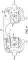
- Figure 4 there is shown a partially cut away view of a radiation treatment apparatus according to an embodiment of the present invention.
- Figure 4 illustrates a printed circuit board (PCB) 120 supporting the OLEDs 102 (for an apparatus having two OLEDs, one for each eye) and shaped to fit on or in an eye mask generally of the form illustrated in Figure 2 , 8 or 9 .
- the area A indicates generally where the user's nose may be when the mask is fitted to the user's face.
- Figure 4 shows a processor 104 and four separate capacitive sensors 110, forming compliance sensors, spaced apart around the periphery of the PCB 120.
- the capacitive sensors extend from the PCB as flaps that may be folded against a user's face.
- the PCB shown in Figure 4 may, as a whole, be considered as a mount for positioning the various elements with respect to the user.
- the PCB can be incorporated into the design of a mask as in Figure 2 , within the mask structure or adhered onto a mask structure. Therefore the mask structure itself may be considered the mount. Forming the main electronic components onto a PCB structure may help enable a simpler, more cost effective manufacturing process.
- the PCB or mount may be of any suitable shape to fit together with any suitable facial mask.
- the PCB or mount may have a different layout and design when used in a bandage or plaster, for example.
- this illustrates in the form of a flow chart the process of determining whether the patient is wearing the apparatus 100 by interpreting the output from a capacitive compliance sensor 110 in a processor 104.
- the processor 104 switches on a small current to the capacitive sensor 110, the current being supplied to a processor pin coupled to one terminal of the capacitive sensor 110.
- a timer controlled by the clock circuit 112 is reset and started.
- the processor waits 30 mS (milliseconds) while counting the number of oscillations of the voltage charging and discharging across the capacitive sensor.
- the timer is stopped once 30 mS is reached and the number of oscillations is read.
- step S14 the status of the sensor is set to OFF.
- This change of state may be used to update information held in the memory 108 or sent to the output 114 indicating when and / or for how long the patient has worn the apparatus.
- the running average is reset and a new average calculation begun with the new reading.
- the power supply to the capacitive sensor is turned off to conserve power. In order to conserve power the compliance monitoring functions may be set to only operate periodically, for instance once per second, such that for the majority of the time the apparatus is in a reduced power mode.
- step S12 If at step S12 it is determined that the count of oscillations is not significantly less than the average value (or is the same, or higher) it is determined that the patient continues to not be wearing the apparatus.
- step S20 the average number of oscillations in a 30 mS period is updated. That is, the average of a predetermined number of previous measurements is updated with the new measurement allowing the sensor to keep track of gradually changing capacitive conditions. The process then returns to step S18.
- step S10 it is determined that the current states of the sensor is OFF (indicating that the patient was wearing the apparatus when the sensor was last checked) then at step S22 a check is made whether the number of oscillations counted in the 30 mS period of time is significantly higher than the average of previous measurements. If the answer is yes then this indicates that the patient has removed the apparatus. Therefore at step S24 the status of the sensor is set to ON. At step S16 the running average is reset and a new average calculation begun with the new reading and at step S18 the power supply to the capacitive sensor is turned off to conserve power.
- step S22 If at step S22 it is determined that the count of oscillations is not significantly higher than the average value (or is the same, or lower) it is determined that the patient continues to be wearing the apparatus.
- step S26 the average number of oscillations in a 30 mS period is updated and the process returns to step S18.
- FIG. 6 this illustrates in the form of a flow chart the main processing loop of a radiation treatment apparatus according to an embodiment of the present invention.
- the flow chart in Figure 6 operates as a continuous loop until the power supply is lost, as is the case for the flow chart of Figure 5 .
- the operation of Figure 6 is designed to conserve power by powering down approximately once per second and by using a lower power and relatively slow 32 kHz clock.
- the processor Upon powering up each cycle the processor is arranged to read the capacitive sensors as described in Figure 5 , update the stored compliance data (or transmit new compliance data) and then power down again.
- the processor checks if the OLED or each OLED is currently on. If the OLEDs are on then the apparatus cannot be powered down, so at step S32 the processor waits 1.1 S. If power down is possible (i.e. the OLED is not switched on) then at step S34 the processor powers down for 1.1 S before turning on and measuring the or each capacitive sensors at step S36. At step S38 the processor determines whether at least one sensor on the left of the apparatus mask and at least one sensor on the right are indicating that the apparatus is being worn. The processor also determines if further radiation emissions are necessary to meet the prescribed radiation emission for that dosage session. If the answer to both questions is yes then at step S40 the or each OLED is switched on or remains on.
- step S42 the or each OLED is switched off.
- step S44 the process updates the timers recording the duration and / or times at which the mask was worn and / or radiation was emitted while the mask was worn. The process then returns to step S30.
- Apparatus 200 incorporates the general principles of the embodiments described above, but is arranged to be worn as a bandage over any area of a user as required.
- the apparatus is used on the arm 201 of a patient.
- the bandage may be tied or adhered to the arm 201 in a known manner.
- the apparatus 200 includes a flexible outer layer 202, which may be soft cotton for example for patient comfort.
- the apparatus 200 also includes a radiation source 204, which in this example is an OLED, on the skin-facing side of the apparatus in use.
- the radiation source is linked to a controller (not shown) which may function in the same way as the processor 104 described above.
- the controller is also linked to a compliance sensor for monitoring the usage of the apparatus 200, in a similar manner as described above.
- the OLED 204, controller and sensor may be formed on a PCB 205 that can effectively be laminated onto the outer layer 202. Compliance can be monitored in the same way with respect to Figures 5 and 6 .
- a further inner layer may be included to help improve patient comfort. Aptly this layer would be transparent at least in the area of the OLED so as to not interfere with the radiation emission.
- the radiation source has been described above as an OLED, this may be any electroluminescent emitter, light emitting device, light emitting cell (LEC), light emitting electrochemical cell (LEEC), LED or similar device.
- the apparatus of the present invention when embodied as a facial mask may take the general form as shown in Figure 1 or Figure 2 , or other similar form to appropriately locate the radiation source in the eye region and encompass the above-described features of the invention.
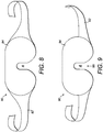
- Figure 8 shows another configuration of a facial mask 80 having a strap or straps 82 and a facial portion 84 for holding the components of the invention described above.
- Figure 9 shows a yet further configuration of a facial mask 90 having a strap or straps 92 and a facial portion 94.
- the strap(s) 92 connect with the facial portion 94 at a lower position on the portion 94 (in the orientation shown on the drawing and in normal use) compared with the mask 80.
- the strap(s) By lowering the relative position of the strap(s) 92, the strap(s) is provided closer to an opening 96 to the area A where a user's nose may be located in use. As such, upon positioning the mask 90 on the head, the tension of the strap(s) 92 acts to increase the width of the opening 96. This may be useful for users with larger than average noses and/or heads.
- the apparatus of the present invention may include one or more moisture detector for detecting the presence of liquid on the apparatus.
- An internal moisture detector may be used to determine whether a user has exposed the apparatus to a wet environment, for example dropping the apparatus in a drink or bath tub, thereby helping to identify the liability for damage to the apparatus.
- a medical apparatus may be provided in which an additional sensor is provided, such as a capacitance sensor, as a user input control on the apparatus.
- the capacitance sensor may be in the form of a button that a user presses to initiate start-up of the apparatus. Then, within a predetermined time length such as 10 seconds from pushing the button, the user should put the apparatus in place on the area to be treated (as confirmed by the other capacitance sensors 110).
- the apparatus then requires a deliberate act by the user to switch on the apparatus prior to the monitoring. This may help positively confirm when the device should be turned on to emit radiation (i.e. an extra check), and may also help positively reinforce to the user the need to comply with the specified treatment regime.
- the sensor element of the apparatus may be in the form of a light emitter and receiver arrangement, for example including an infrared light emitter at one location of the apparatus and a photodetector or diode located at another location of the apparatus.
- the emitter and receiver may be respectively located on either side of a nose locating area of a facial mask, such that by placement of the mask on a user's face, the user's nose will block any infrared light from the emitter being received at the receiver. That is, the "line of sight" of the infrared radiation is blocked by the nose when the mask is being worn.
- the receiver will be able to provide an indication (e.g.
- a signal to monitor whether the mask is in place on the user's face, and optionally also for how long the mask is in place on the user's face by providing a signal to a controller in a similar manner as described above.
- Such an arrangement may be used instead of the compliance sensor 110 described above, or may be used as an addition to one or more compliance sensor, such as the capacitance sensor described above. Provision of such an arrangement may help to prevent a user purposely or inadvertently 'cheating the system', for example where a facial mask is worn or rides up above the eye area but is still in contact with the skin.
- apparatus may also be programmed with a specified, predetermined dosage regime, e.g. treatment time length and number of treatments (e.g. 8 hours treatment for 10 days), and light intensity/luminance level.
- a specified, predetermined dosage regime e.g. treatment time length and number of treatments (e.g. 8 hours treatment for 10 days), and light intensity/luminance level.
- the intensity may be variable, for instance at a less bright level at the beginning of a treatment period (as the user gets used to the apparatus or begins to fall asleep) and increases to a further brightness level for a next part of the treatment period.
- the apparatus of the invention may be designed to receive instructions on a dosage regime that may be set by a doctor or other instructor.
- the steps for receiving instructions may be opposite to the above-described sending of information from the apparatus.
- a RF receiver may be included that receives an input and sends the signal to processor 104.
- the processor may then control the radiation source 107 in accordance with the instructions. This may be useful if the dosage regime for a patient needs to be changed over time, for example as their health improves.
- a dosage scheme of radiation can be automatically delivered to a patient when the apparatus is secured in place on the patient.
- the apparatus By monitoring when and for how long the patient wears the apparatus it can be monitored whether the full dosage scheme is delivered to the patient: that is, the patient's compliance with the dosage scheme can be monitored.
Landscapes
- Health & Medical Sciences (AREA)
- Engineering & Computer Science (AREA)
- Biomedical Technology (AREA)
- Animal Behavior & Ethology (AREA)
- Public Health (AREA)
- Veterinary Medicine (AREA)
- General Health & Medical Sciences (AREA)
- Life Sciences & Earth Sciences (AREA)
- Vascular Medicine (AREA)
- Ophthalmology & Optometry (AREA)
- Heart & Thoracic Surgery (AREA)
- Pathology (AREA)
- Nuclear Medicine, Radiotherapy & Molecular Imaging (AREA)
- Radiology & Medical Imaging (AREA)
- Otolaryngology (AREA)
- Radiation-Therapy Devices (AREA)
- Measuring And Recording Apparatus For Diagnosis (AREA)
- Apparatus For Radiation Diagnosis (AREA)
Description
- The present invention relates to a medical apparatus. In particular, but not exclusively, the present invention relates to a medical apparatus such as a facial mask, bandage or plaster for directing radiation into a patient's eyes or other area requiring treatment.
- Phototherapy has been used for various therapeutic and cosmetic purposes. It generally involves the use of specific wavelengths of light radiation being administered to a patient. Phototherapy may be used to treat chronic infections such as hepatitis (A, B or C), bacterial infections, wounds, precancer conditions, seasonal affective disorder (SAD), various dermatological and cosmetic purposes such as skin rejuvenation, and various eye diseases such as diabetic macular edema, retinopathy of prematurity, wet or dry age-related macular degeneration and diabetic retinopathy, for example.
- Diabetic retinopathy is a condition in which damage to the retina in the eye occurs and is caused by diabetes. More specifically, diabetic retinopathy is the result of microvascular retinal changes where hyperglycemia-induced intramural pericyte death and thickening of the basement membrane cause damage to the wall of blood vessels in the eye. This damage changes the formation of the blood-retinal barrier and also makes the retinal blood vessels become more permeable. Small blood vessels, such as those in the eye, are particularly vulnerable to poor blood sugar control. An overaccumulation of glucose and/or fructose damages the blood vessels in the retina. Damaged blood vessels are likely to leak fluid and lipids onto the macula. This condition can therefore lead to impaired vision and ultimately blindness. The condition can be treated by preventing the complete dark adaptation of the eye by providing some degree of light radiation to the eyes or eyelids during sleep. This is because, during dark adaptation, the eye requires an increased oxygen level, and thus the blood vessels must work harder during dark adaptation. Therefore by preventing complete dark adaptation of the eye, the blood vessels are less stressed and can rejuvenate over time. For diabetic retinopathy, preferably light having a wavelength of between around 460 to 550 nm is administered to the eyes or eyelids, which corresponds to the scotopic sensitivity of the eye. Of course for other diseases or conditions, other wavelength ranges may be useful.
- It has been found useful to administer the radiation to the eye area by providing a mask type of device for a patient to wear during sleep, the mask configured to be secured over the patient's head to cover the eye area, and adapted to include light emitting sources in the region of the eyes. The light sources may be electroluminescent emitters, light emitting devices, light emitting cells (LECs), light emitting electrochemical cells (LEECs), LEDs or OLEDs, for example, and are arranged to emit light towards the eye area. The radiation acts to stimulate the rods of the eye leading to hyperpolarization and desensitization of the rod cells, which lowers their metabolic rates and hence results in a drop in oxygen consumption in the retina.
-
WO2011/135362 discloses a radiation treatment apparatus for directing electromagnetic radiation into a patient's eyes. Radiation treatment may be started or stopped by a patient input (on/off switch) to switch at least one organic semiconductor radiation emitting device on or off. Preferably the or each organic semiconductor radiation emitting device comprises an organic light emitting diode (OLED). Advantageously, the heat output from an OLED is less that that generated by a conventional light emitting diode (LED). OLEDs also emit light over a larger surface area than conventional LEDs, which assists in ensuring that radiation is directed correctly through the patient's eyelids and pupil to reach the retina of the eye. The or each OLED is mounted in a mask, goggles or a visor so that the electromagnetic radiation emitted by the or each OLED is directed into at least one eye of the patient, with the or each OLED in a predetermined position relative to the or each eye of the patient. Preferably, the mask, goggles or visor are provided with a securing strap or other means for securing the or each OLED to the patients face or head. - The radiation treatment apparatus disclosed
WO2011/135362 may include a power supply and a controller for controlling the supply of power to the OLEDs. This provides the flexibility to vary the time and intensity of radiation exposure as part of a treatment regime. The duration and conditions of operation of the OLEDs may be recorded in a memory. In addition, sensor means may be provided to sense the surroundings of the apparatus, for instance to deactivate the OLEDs during daylight, or to take account of the body temperature or movement of the patient. - However, it is generally known that some patients do not adhere to the instructions of their doctor, physician or other advisor in terms of following the instructed treatment dosage and/or treatment regime, and/or follow the instructions on the patient information leaflet accompanying a medicine or apparatus.
- In terms of a radiation treatment apparatus as described in
WO2011/135362 , the actual usage of the device by a patient in the correct manner (e.g. for the correct period of time and for the correct number of days, etc.), as prescribed by a doctor for example, cannot be guaranteed. - The present invention seeks to at least partly mitigate the above-mentioned problems.
- According to a first aspect of the present invention there is provided a medical apparatus as described in claim 1.
- Certain embodiments of the present invention provide the advantage that the apparatus can itself determine an indication of how long the apparatus has been used by the patient.
- Certain embodiments of the present invention provide the advantage that a patient's usage of the apparatus can be recorded and/or transmitted for monitoring by a doctor or other monitoring service. Thus, compliance by the patient with a treatment regime can be determined. In some cases, a patient having knowledge that such compliance is being monitored will have a higher motivation to actually follow the treatment regime, thereby improving compliance with the instructed treatment regime.
- Certain embodiments of the invention provide the advantage that data corresponding to a patient's usage of the apparatus can be stored, and/or transmitted continuously, intermittently or upon request to a receiver (such as a computer operated by the patient's doctor).
- Embodiments of the invention are further described hereinafter with reference to the accompanying drawings, in which:
-
Figure 1 illustrates an exploded perspective view of a radiation treatment apparatus; -
Figure 2 illustrates an alternative radiation treatment apparatus; -
Figure 3 schematically illustrates a radiation treatment apparatus according to an embodiment of the present invention; -
Figure 4 is a partially cut away view of a radiation treatment apparatus according to an embodiment of the present invention; -
Figure 5 is a flow chart describing how capacitive sensors are used within a radiation treatment apparatus according to an embodiment of the present invention; -
Figure 6 is a flow chart describing the operation of a radiation treatment apparatus according to an embodiment of the present invention; and -
Figures 7a and 7b illustrate an alternative radiation treatment apparatus. - In the drawings like reference numerals refer to like parts.
- Certain elements of the apparatus described in
WO2011/135362 may be used with the present invention. - As illustrated in
Figure 1 , an exploded perspective view of aradiation treatment apparatus 2 as disclosed inWO2011/135362 comprises supports (or mounts) 4, 6 to be located adjacent to the eyes of a patient, the supports 4, 6 each supporting arespective OLED eyelids adjustable strap 12 couples the supports 4, 6 together so that the spacing between theOLEDs securing strap 18 secures the apparatus to the patients head. TheOLEDs battery 20 housed in at least onerecess 22 and activated by aswitch 24. -
WO2011/135362 discloses a range of alternative embodiments, for instance mounting the OLEDs in a face mask. The face mask may be formed from a flexible material. The face mask may be secured by a strap similar tostrap 18 shown inFigure 1 , or it may, for instance, be adhesively mounted to the patient's eye socket or face. Alternatively, the OLEDs could be integrated into a visor mounted to the patient's head via a head strap.Figure 2 illustrates an alternative radiation treatment apparatus disclosed inWO2011/135362 that takes the form of a mask. The mask comprises aflexible portion 30 to conform to the shape of the patient's face. Theflexible portion 30 extends to formstraps 32 which extend either around the patient's head or are secured by the patient's ears passing throughapertures 34. TheOLEDs Figure 2 further illustrates one ormore sensors 36, for instance to sense ambient light levels, body temperature or movement of the patient for use in controlling the operation of the apparatus to minimise disturbance to the user's sleep. - The present invention provides a radiation treatment apparatus comprising an improvement to the radiation treatment apparatuses disclosed in
WO2011/135362 . As noted above, some patients may not correctly follow a treatment regime prescribed by a doctor. Specifically, some patients may not correctly wear the apparatus or may not wear the apparatus at all, for instance removing the apparatus before the full prescribed radiation exposure has been reached for that treatment session. The present invention allows compliance with a treatment regime to be monitored by detecting when or for how long the apparatus is worn. This allows a determination to be made whether the correct radiation exposure has been delivered to the patient. - Referring now to
Figure 3 , this schematically illustrates components of anapparatus 100 in accordance with an embodiment of the present invention. It will be appreciated that the purpose ofFigure 3 is to present the main functional units of an apparatus in accordance with an embodiment of the present invention, and places no limitation on the actual structure of the apparatus. However, one such structure would be a structure as depicted inFigure 1 orFigure 2 , for example. Theapparatus 100 comprises at least oneradiation source 102, for instance at least one electroluminescent emitter, in this case an OLED. Theradiation source 102 or each radiation source may be positioned in or on a mask, goggles or visor, or other such support structure or mount so as to be placed in a predetermined position relative to a patient's eye (or other area to be treated). The support structure may be for example as generally shown inFigures 1 and2 and as described inWO2011/135362 , and so will not be further described here. The apparatus further comprises aprocessor 104 and a battery 106 (or other source of power, for instance a power supply socket allowing a power supply wire to be coupled to the apparatus 100). Thebattery 106 is coupled to theprocessor 104 and theradiation source 102 so as to enable the supply of power to both. Theprocessor 104 is coupled to theradiation source 102 so as to control the operation of the radiation source, and in particular to turn theradiation source 102 on and off in accordance with a prescribed treatment regime. The apparatus further comprises amemory 108 coupled to theprocessor 104. Thememory 108 is arranged to store instructions for controlling theprocessor 104 and data relating to the treatment regime, for instance intensity of electromagnetic radiation emitted by theradiation source 102. -
Figure 3 further illustrates acompliance sensor 110 coupled to theprocessor 104. The compliance sensor is arranged to provide a signal to theprocessor 104 indicative of whether theapparatus 100 is being worn by the patient. In one embodiment, to be described in greater detail below, thecompliance sensor 110 comprises a capacitive sensor arranged to provide a signal to theprocessor 104 indicative of the capacitance at the sensor, which can be interpreted to determine whether the sensor is close to or in contact with skin (indicating that theapparatus 100 is being worn) or whether the sensor is close to or in contact with air (indicating that theapparatus 100 is not being worn).Figure 3 further illustrates aclock circuit 112 coupled to theprocessor 104. Theclock circuit 112 is arranged to provide a timing signal allowing theprocessor 104 to calculate the duration for which theapparatus 100 has been worn, or the times at which the apparatus is put on or taken off, or both. Data relating to when and / or for how long the apparatus has been worn (hereinafter compliance data) may be stored inmemory 108. Alternatively, or in addition, the compliance data may be passed from theprocessor 104 to anoutput circuit 114 for transmission to another device. For instance, the output circuit may be a radio frequency (RF) transmitter arranged to transmit compliance data wirelessly to a patient's computer, or directly or indirectly to a doctor's computer to allow compliance of the patient with a treatment regime to be monitored. Alternatively, theoutput 114 could be used to download compliance data periodically from the memory, for instance when the patient visits the doctor. - In addition to passively recording when and / or for how long the patient has worn the apparatus, the signal from the
compliance sensor 110 may be used to assist theprocessor 104 in controlling the radiation source. This may be to ensure that theradiation source 102 is only activated when theapparatus 100 is being worn. Additionally, theprocessor 104 may be adapted to monitor the duration of radiation exposure while theapparatus 100 is being worn such that further exposure is prevented, i.e. the radiation source is switched off, once the prescribed dosage for that dosage session has been reached. Data relating to the duration of use, that is data recording the patient's radiation exposure from the OLED whilst wearing the mask may form part of the compliance data. By monitoring when the apparatus is worn, embodiments of the present invention provide an apparatus capable of autonomously delivering a specific radiation dosage according to a predetermined treatment regime to the eye, or eyes, or other area of a patient. Embodiments of the present invention further provide the ability to make records of, and monitor, compliance with a predetermined treatment regime. - A capacitive sensor, such as may be used to form the
compliance sensor 110, is operated by taking a first measurement of the capacitance of the sensor at a first time and at a second, later, time taking a second measurement of the capacitance of the sensor. When a capacitive sensor is exposed to air the capacitance varies significantly due to natural variations in the surroundings of the sensor. Conversely, when a capacitive sensor is in contact with, or in close proximity to, a patient's skin the capacitance remains more stable. Consequently, if the first and second measurements of the capacitance of the sensor are close to one another (within a predetermined tolerance) then this indicates that the sensor is in contact with or close to the patient's skin (and hence indicates that the apparatus is being worn). If the two measurements are further apart than the predetermined tolerance, then this indicates that the apparatus is not being worn. In one embodiment a capacitive sensor periodically charges and discharges at a frequency determined by its capacitance (which, as noted above varies according to the surroundings of the sensor). The capacitive sensor may transmit this periodic signal to theprocessor 104. By comparison to a regular timing signal received from theclock 112, the frequency of the signal from the sensor can be determined and compared with earlier readings to determine whether the apparatus is being worn. - Alternatives to capacitive sensors to form the
compliance sensor 110 include thermal sensors, ultrasonic sensors, photodiodes, a strain gauge that is for example coupled to an apparatus securing strap (to measure strain as the strap is stretched when pulling on the apparatus) or coupled to another portion of the apparatus and capable of measuring bending as the apparatus is put on, and a blood oxygen monitor. Indeed, any sensor known in the art capable of providing an indication whether the apparatus is being worn may be used. Where a capacitive sensor, in particular, is used it can be desirable to use multiple capacitive sensors such as two sensors, one on either side of a mask, three sensors, or four sensors spaced apart around a mask to accommodate variations in the shape of patient's faces. For instance, for some patients not all of the sensors may contact the patient's face. There are surprisingly large variations in facial shapes due to genetics and origin. In some embodiments it may be sufficient for one capacitive sensor to register that it is in contact with, or in close proximity to, the patient's skin to determine that the apparatus is being correctly worn. Alternatively, it may be necessary that every sensor, or a predetermined number of sensors, register that they are in contact with, or in close proximity to, the patient's skin to determine that the apparatus is being correctly worn. The higher number of sensors may help to obtain a more reliable result. - As noted above, compliance data may be stored within the
apparatus 100 inmemory 108, or compliance data may be transmitted from theapparatus 100 continuously or intermittently, or both. The method of sending data, e.g. compliance data, to a device (for example a computer), may be known as machine-to-machine monitoring (M2M). In a first exemplary embodiment, theoutput circuit 114 may be an RFID chip such that compliance data stored inmemory 108 may be retrieved wirelessly from the apparatus periodically, for instance when the patient visits their doctor. The apparatus may optionally include a recharging element using an induction to power the RFID chip by induction (rather than using battery 106). - In a second exemplary embodiment,
output circuit 114 may comprise a Bluetooth (RTM) transmitter arranged to transmit compliance data to an associated device such as a mobile telephone or a computer, where that data may be stored or further transmitted, for instance ultimately to a doctor or other person responsible for monitoring the patient's compliance with the treatment regime. It will be appreciated that further variations are possible, for instance using a wired connection to the apparatus. Wired connections may, for example, be via USB, FireWire™, Thunderbolt™ or Lightning™. Alternatively, data may be communicated via "Li-Fi" (the transmission of communication using visible light). - An application (or 'app') specifically created to interact with the mask may be installed on a mobile telephone (cellular phone), which may be programmed to store information relating to the use of the mask. For example, the application may be configured to log mask wear history (e.g. including total duration of wear and specific times of wear) and/or set reminders to tell the patient when they need to wear the mask. The application may also further transmit data to a doctor or other person responsible for monitoring the patient's compliance with the treatment regime. It will be appreciated that software of similar capabilities may provide the same function when installed on any PC, tablet or other suitable electronic device. The data from the mask may be transmitted to the application and/or the software (installed on any suitable electronic device) via any wireless or wired means.
- M2M monitoring may use short range wireless communication (for example in homes and hospitals) which may be via personal area networks (e.g. Bluetooth™, Zigbee™, MyWi™) or local area networks (e.g. Wi-Fi).
- Telehealth refers to the delivery of health-related services and/or information via telecommunication technologies (and it is appreciated that this may be known by other names elsewhere). Telecare is a similar system in which a patient is connected with a monitoring centre through which an alarm is raised if the patient requires assistance. The mask of the present invention may be integrated with such systems to monitor health and/or transmit data to any required locations. For example, for long range monitoring (e.g. from a home to a doctor in a different location), these systems may be utilized to provide communication via the internet.
- Referring now to
Figure 4 , there is shown a partially cut away view of a radiation treatment apparatus according to an embodiment of the present invention. Specifically,Figure 4 illustrates a printed circuit board (PCB) 120 supporting the OLEDs 102 (for an apparatus having two OLEDs, one for each eye) and shaped to fit on or in an eye mask generally of the form illustrated inFigure 2 ,8 or 9 . The area A indicates generally where the user's nose may be when the mask is fitted to the user's face.Figure 4 shows aprocessor 104 and four separatecapacitive sensors 110, forming compliance sensors, spaced apart around the periphery of thePCB 120. The capacitive sensors extend from the PCB as flaps that may be folded against a user's face. There is also shown a powersupply transistor chip 122 for controlling the supply of power to the OLEDs and theprocessor 104. In the embodiment shown inFigure 4 there is asingle processor 104, which additionally implements the functions of theclock 112,memory 108 andoutput 114 shown inFigure 3 . It will be appreciated that the PCB shown inFigure 4 may, as a whole, be considered as a mount for positioning the various elements with respect to the user. The PCB can be incorporated into the design of a mask as inFigure 2 , within the mask structure or adhered onto a mask structure. Therefore the mask structure itself may be considered the mount. Forming the main electronic components onto a PCB structure may help enable a simpler, more cost effective manufacturing process. Of course it will be realised that the PCB or mount may be of any suitable shape to fit together with any suitable facial mask. The PCB or mount may have a different layout and design when used in a bandage or plaster, for example. - Referring now to
Figure 5 , this illustrates in the form of a flow chart the process of determining whether the patient is wearing theapparatus 100 by interpreting the output from acapacitive compliance sensor 110 in aprocessor 104. At step S2 theprocessor 104 switches on a small current to thecapacitive sensor 110, the current being supplied to a processor pin coupled to one terminal of thecapacitive sensor 110. At step S4 a timer controlled by theclock circuit 112 is reset and started. At step S6 the processor waits 30 mS (milliseconds) while counting the number of oscillations of the voltage charging and discharging across the capacitive sensor. At step S8 the timer is stopped once 30 mS is reached and the number of oscillations is read. At step S10 a check is made whether the capacitive sensor is turned on. That is, a check is made whether the previous readings from the capacitive sensor indicate that the apparatus is being worn. If the capacitive sensor is ON this indicates that the previous recorded state of the sensor is that the apparatus is not being worn (the sensor is not in contact with skin. If the capacitive sensor is on then at step S12 a check is made whether the number of oscillations counted in the 30 mS period of time is significantly lower than the average of previous measurements. When a capacitive sensor is in contact with, or in close proximity to, skin the capacitive load is increased, which lowers the number of oscillations. The processor checks to see whether the oscillation count is lower than the average by a predetermined proportion or amount. If the answer is yes then this indicates that the patient has put the apparatus on, thereby bringing the sensor into contact with skin. Therefore at step S14 the status of the sensor is set to OFF. This change of state may be used to update information held in thememory 108 or sent to theoutput 114 indicating when and / or for how long the patient has worn the apparatus. Given the change of state, at step S16 the running average is reset and a new average calculation begun with the new reading. At step S18 the power supply to the capacitive sensor is turned off to conserve power. In order to conserve power the compliance monitoring functions may be set to only operate periodically, for instance once per second, such that for the majority of the time the apparatus is in a reduced power mode. If at step S12 it is determined that the count of oscillations is not significantly less than the average value (or is the same, or higher) it is determined that the patient continues to not be wearing the apparatus. At step S20 the average number of oscillations in a 30 mS period is updated. That is, the average of a predetermined number of previous measurements is updated with the new measurement allowing the sensor to keep track of gradually changing capacitive conditions. The process then returns to step S18. - Similarly, if at step S10 it is determined that the current states of the sensor is OFF (indicating that the patient was wearing the apparatus when the sensor was last checked) then at step S22 a check is made whether the number of oscillations counted in the 30 mS period of time is significantly higher than the average of previous measurements. If the answer is yes then this indicates that the patient has removed the apparatus. Therefore at step S24 the status of the sensor is set to ON. At step S16 the running average is reset and a new average calculation begun with the new reading and at step S18 the power supply to the capacitive sensor is turned off to conserve power. If at step S22 it is determined that the count of oscillations is not significantly higher than the average value (or is the same, or lower) it is determined that the patient continues to be wearing the apparatus. At step S26 the average number of oscillations in a 30 mS period is updated and the process returns to step S18.
- Referring now to
Figure 6 , this illustrates in the form of a flow chart the main processing loop of a radiation treatment apparatus according to an embodiment of the present invention. The flow chart inFigure 6 operates as a continuous loop until the power supply is lost, as is the case for the flow chart ofFigure 5 . Similar toFigure 5 , the operation ofFigure 6 is designed to conserve power by powering down approximately once per second and by using a lower power and relatively slow 32 kHz clock. Upon powering up each cycle the processor is arranged to read the capacitive sensors as described inFigure 5 , update the stored compliance data (or transmit new compliance data) and then power down again. - At step S30 the processor checks if the OLED or each OLED is currently on. If the OLEDs are on then the apparatus cannot be powered down, so at step S32 the processor waits 1.1 S. If power down is possible (i.e. the OLED is not switched on) then at step S34 the processor powers down for 1.1 S before turning on and measuring the or each capacitive sensors at step S36. At step S38 the processor determines whether at least one sensor on the left of the apparatus mask and at least one sensor on the right are indicating that the apparatus is being worn. The processor also determines if further radiation emissions are necessary to meet the prescribed radiation emission for that dosage session. If the answer to both questions is yes then at step S40 the or each OLED is switched on or remains on. If the answer to at least one question is no then at step S42 the or each OLED is switched off. At step S44 the process updates the timers recording the duration and / or times at which the mask was worn and / or radiation was emitted while the mask was worn. The process then returns to step S30.
- A further embodiment of the present invention is shown in
Figures 7a and 7b .Apparatus 200 incorporates the general principles of the embodiments described above, but is arranged to be worn as a bandage over any area of a user as required. Here the apparatus is used on thearm 201 of a patient. The bandage may be tied or adhered to thearm 201 in a known manner. As shown in the cross-sectional view ofFigure 7b , theapparatus 200 includes a flexibleouter layer 202, which may be soft cotton for example for patient comfort. Theapparatus 200 also includes aradiation source 204, which in this example is an OLED, on the skin-facing side of the apparatus in use. The radiation source is linked to a controller (not shown) which may function in the same way as theprocessor 104 described above. In turn, the controller is also linked to a compliance sensor for monitoring the usage of theapparatus 200, in a similar manner as described above. For ease, theOLED 204, controller and sensor may be formed on aPCB 205 that can effectively be laminated onto theouter layer 202. Compliance can be monitored in the same way with respect toFigures 5 and6 . Optionally, a further inner layer may be included to help improve patient comfort. Aptly this layer would be transparent at least in the area of the OLED so as to not interfere with the radiation emission. - Various modifications to the detailed designs as described above are possible. For example at least some of the separate functional components illustrated in
Figure 3 may be reduced in number by combining their functions into a single processor. The skilled person will appreciate that the present invention may be implemented in hardware or software as required. - Although the radiation source has been described above as an OLED, this may be any electroluminescent emitter, light emitting device, light emitting cell (LEC), light emitting electrochemical cell (LEEC), LED or similar device.
- Although discrete, intermittent measurements have been described above, it will be realised that continuous monitoring of radiation emission or wear by the user may be possible.
- The apparatus of the present invention when embodied as a facial mask may take the general form as shown in
Figure 1 orFigure 2 , or other similar form to appropriately locate the radiation source in the eye region and encompass the above-described features of the invention.Figure 8 shows another configuration of afacial mask 80 having a strap or straps 82 and afacial portion 84 for holding the components of the invention described above.Figure 9 shows a yet further configuration of afacial mask 90 having a strap or straps 92 and afacial portion 94. The strap(s) 92 connect with thefacial portion 94 at a lower position on the portion 94 (in the orientation shown on the drawing and in normal use) compared with themask 80. By lowering the relative position of the strap(s) 92, the strap(s) is provided closer to anopening 96 to the area A where a user's nose may be located in use. As such, upon positioning themask 90 on the head, the tension of the strap(s) 92 acts to increase the width of theopening 96. This may be useful for users with larger than average noses and/or heads. - As an optional additional feature, the apparatus of the present invention may include one or more moisture detector for detecting the presence of liquid on the apparatus. An internal moisture detector may be used to determine whether a user has exposed the apparatus to a wet environment, for example dropping the apparatus in a drink or bath tub, thereby helping to identify the liability for damage to the apparatus.
- As an alternative to the above-described arrangement, a medical apparatus may be provided in which an additional sensor is provided, such as a capacitance sensor, as a user input control on the apparatus. The capacitance sensor may be in the form of a button that a user presses to initiate start-up of the apparatus. Then, within a predetermined time length such as 10 seconds from pushing the button, the user should put the apparatus in place on the area to be treated (as confirmed by the other capacitance sensors 110). By incorporating such a user-operated sensor, the apparatus then requires a deliberate act by the user to switch on the apparatus prior to the monitoring. This may help positively confirm when the device should be turned on to emit radiation (i.e. an extra check), and may also help positively reinforce to the user the need to comply with the specified treatment regime.
- In another alternative arrangement, the sensor element of the apparatus may be in the form of a light emitter and receiver arrangement, for example including an infrared light emitter at one location of the apparatus and a photodetector or diode located at another location of the apparatus. Aptly, the emitter and receiver may be respectively located on either side of a nose locating area of a facial mask, such that by placement of the mask on a user's face, the user's nose will block any infrared light from the emitter being received at the receiver. That is, the "line of sight" of the infrared radiation is blocked by the nose when the mask is being worn. Thereby, the receiver will be able to provide an indication (e.g. a signal) to monitor whether the mask is in place on the user's face, and optionally also for how long the mask is in place on the user's face by providing a signal to a controller in a similar manner as described above. Such an arrangement may be used instead of the
compliance sensor 110 described above, or may be used as an addition to one or more compliance sensor, such as the capacitance sensor described above. Provision of such an arrangement may help to prevent a user purposely or inadvertently 'cheating the system', for example where a facial mask is worn or rides up above the eye area but is still in contact with the skin. - In addition to the above-described functions, apparatus according to the invention may also be programmed with a specified, predetermined dosage regime, e.g. treatment time length and number of treatments (e.g. 8 hours treatment for 10 days), and light intensity/luminance level. Aptly the intensity may be variable, for instance at a less bright level at the beginning of a treatment period (as the user gets used to the apparatus or begins to fall asleep) and increases to a further brightness level for a next part of the treatment period.
- In a further variation, the apparatus of the invention may be designed to receive instructions on a dosage regime that may be set by a doctor or other instructor. The steps for receiving instructions may be opposite to the above-described sending of information from the apparatus. For example, a RF receiver may be included that receives an input and sends the signal to
processor 104. The processor may then control theradiation source 107 in accordance with the instructions. This may be useful if the dosage regime for a patient needs to be changed over time, for example as their health improves. - With the above-described invention, a dosage scheme of radiation can be automatically delivered to a patient when the apparatus is secured in place on the patient. By monitoring when and for how long the patient wears the apparatus it can be monitored whether the full dosage scheme is delivered to the patient: that is, the patient's compliance with the dosage scheme can be monitored.
- It will be clear to a person skilled in the art that features described in relation to any of the embodiments described above can be applicable interchangeably between the different embodiments. The embodiments described above are examples to illustrate various features of the invention.
- Throughout the description and claims of this specification, the words "comprise" and "contain" and variations of them mean "including but not limited to", and they are not intended to (and do not) exclude other moieties, additives, components, integers or steps. Throughout the description and claims of this specification, the singular encompasses the plural unless the context otherwise requires. In particular, where the indefinite article is used, the specification is to be understood as contemplating plurality as well as singularity, unless the context requires otherwise.
- Features, integers, characteristics, compounds, chemical moieties or groups described in conjunction with a particular aspect, embodiment or example of the invention are to be understood to be applicable to any other aspect, embodiment or example described herein unless incompatible therewith. All of the features disclosed in this specification (including any accompanying claims and drawings), may be combined in any combination, except combinations where at least some of such features and/or steps are mutually exclusive. The invention is not restricted to the details of any foregoing embodiments.
- The reader's attention is directed to all papers and documents which are filed concurrently with or previous to this specification in connection with this application and which are open to public inspection with this specification.
Claims (12)
- A medical apparatus, comprising:a radiation source for emitting radiation towards at least one eye of a patient;a mount element arranged to be worn by the patient for positioning the radiation source in a predetermined position relative to the at least one eye, wherein the mount element comprises a mask, goggles or a visor arranged to be attached to the patient's face or head, for positioning the radiation source in a predetermined position relative to the at least one eye of the patient;a sensor element arranged to provide a signal indicative of whether the apparatus is being worn by the patient; andat least one controller arranged to receive the signal from the sensor, and to determine whether the apparatus is being worn by the patient, and to determine and record duration data indicative of the duration for which the radiation source emits radiation whilst the apparatus is being worn by the patient.
- A medical apparatus as claimed in claim 1, wherein the controller is further arranged to control the operation of the radiation source.
- A medical apparatus as claimed in claim 2 wherein the controller is arranged to control the operation of the radiation source such that radiation is emitted when the signal received from the sensor element indicates that the apparatus is being worn by the patient.
- A medical apparatus according to any preceding claim, wherein the radiation source comprises an organic light emitting diode (OLED).
- A medical apparatus according to claim 4 when dependent on claim 4, wherein the radiation source comprises a pair of OLEDs supported by the mount such that when the apparatus is used by a patient each OLED is in a predetermined position relative to at least one eye of the patient.
- A medical apparatus as claimed in any preceding claim further comprising at least one further sensor element arranged to provide a signal indicative of whether the apparatus is being worn by the patient.
- A medical apparatus according to any preceding claim, wherein the or each sensor element comprises a capacitive sensor supported by the mount such that when the apparatus is worn by a patient the capacitive sensor is in close proximity to the patient's skin.
- A medical apparatus according to any preceding claim, wherein the or each sensor element comprises a light emitter and receiver arrangement supported by the mount such that when the apparatus is worn by a patient the receiver is prevented from receiving light from the light emitter.
- A medical apparatus according to any preceding claim, wherein the controller is arranged to control the radiation source such that radiation is emitted when the signal received from the sensor element indicates that the apparatus is being worn by the patient only if a predetermined radiation emission dosage has not been exceeded.
- A medical apparatus according to any preceding claim, further comprising a memory component arranged to store the duration data.
- A medical apparatus according to any preceding claim, further comprising an output circuit arranged to transmit the duration data.
- A medical apparatus according to claim 9, wherein the output circuit comprises an RFID circuit arranged to transmit the duration data to an associated RFID receiver.
Applications Claiming Priority (2)
| Application Number | Priority Date | Filing Date | Title |
|---|---|---|---|
| GBGB1203005.2A GB201203005D0 (en) | 2012-02-22 | 2012-02-22 | Medical apparatus and method |
| PCT/GB2013/050254 WO2013124615A1 (en) | 2012-02-22 | 2013-02-04 | Medical apparatus and method |
Publications (2)
| Publication Number | Publication Date |
|---|---|
| EP2817065A1 EP2817065A1 (en) | 2014-12-31 |
| EP2817065B1 true EP2817065B1 (en) | 2017-04-05 |
Family
ID=45939977
Family Applications (1)
| Application Number | Title | Priority Date | Filing Date |
|---|---|---|---|
| EP13703874.1A Active EP2817065B1 (en) | 2012-02-22 | 2013-02-04 | Medical apparatus |
Country Status (14)
| Country | Link |
|---|---|
| US (2) | US20150018900A1 (en) |
| EP (1) | EP2817065B1 (en) |
| JP (1) | JP2015509399A (en) |
| KR (1) | KR102024412B1 (en) |
| CN (1) | CN104245047B (en) |
| AU (1) | AU2013223846B2 (en) |
| BR (1) | BR112014020761B1 (en) |
| CA (1) | CA2865374C (en) |
| DK (1) | DK2817065T3 (en) |
| ES (1) | ES2632055T3 (en) |
| GB (1) | GB201203005D0 (en) |
| IN (1) | IN2014DN07524A (en) |
| MX (1) | MX358673B (en) |
| WO (1) | WO2013124615A1 (en) |
Cited By (4)
| Publication number | Priority date | Publication date | Assignee | Title |
|---|---|---|---|---|
| CN110227009A (en) * | 2019-06-11 | 2019-09-13 | 郭小香 | A kind of adjustable type protective device for medical ophthalmology |
| US11253352B2 (en) | 2016-10-03 | 2022-02-22 | California Institute Of Technology | Radioluminescent phototherapy eye device |
| US11400307B2 (en) | 2018-01-31 | 2022-08-02 | California Institute Of Technology | Controllable ocular phototherapy |
| US11850444B2 (en) | 2012-02-22 | 2023-12-26 | Polyphotonix Limited | Medical apparatus and method |
Families Citing this family (14)
| Publication number | Priority date | Publication date | Assignee | Title |
|---|---|---|---|---|
| AT516326B1 (en) | 2014-09-29 | 2016-07-15 | Pocket Sky Og | Device for signal transmission to the eye |
| KR102415906B1 (en) | 2015-04-14 | 2022-07-01 | 엘지이노텍 주식회사 | Wearable device and method for operating thereof |
| CN105125338A (en) * | 2015-08-06 | 2015-12-09 | 成都康拓邦科技有限公司 | Medical instrument for relieving eyeground vasculopathy and control method of medical instrument |
| EP3437695A4 (en) * | 2016-03-29 | 2019-12-04 | Double H Ltd. | Wearable device for reducing body fat using leds and method for operating same |
| US10405800B2 (en) | 2016-07-13 | 2019-09-10 | Capsule Technologies, Inc. | Methods, systems, and apparatuses for detecting activation of an electronic device |
| US10610179B2 (en) * | 2017-06-05 | 2020-04-07 | Biosense Webster (Israel) Ltd. | Augmented reality goggles having X-ray protection |
| US11290818B1 (en) * | 2018-07-11 | 2022-03-29 | Apple Inc. | Wearable electronic device with speakers and sensors |
| CN108783778A (en) * | 2018-07-24 | 2018-11-13 | 北京夏禾科技有限公司 | wearable OLED device |
| KR20200133071A (en) * | 2019-05-16 | 2020-11-26 | 주식회사 엘지생활건강 | A face care device and a mask sheet |
| CN111310143A (en) * | 2020-02-17 | 2020-06-19 | Oppo广东移动通信有限公司 | User identification method, user identification device, electronic device, and storage medium |
| EP3888530A1 (en) * | 2020-03-30 | 2021-10-06 | Oxama S.r.l. | Facial device for monitoring biomedical parameters of a user |
| US20230364420A1 (en) * | 2020-09-17 | 2023-11-16 | Cosmoaesthetics Pty Ltd | A headset for ocular dermal therapy |
| US20220105356A1 (en) * | 2020-10-01 | 2022-04-07 | Osram Opto Semiconductors Gmbh | Portable device for treating a patient with light and method for operating the portable device |
| CN114225219B (en) * | 2022-01-26 | 2022-09-30 | 云南贝泰妮生物科技集团股份有限公司 | Domestic radio frequency beauty instrument self-starting system and domestic radio frequency beauty equipment |
Family Cites Families (27)
| Publication number | Priority date | Publication date | Assignee | Title |
|---|---|---|---|---|
| JPS5932411A (en) | 1982-06-25 | 1984-02-21 | 松下電工株式会社 | Hair dryer |
| JPS639453A (en) * | 1986-06-30 | 1988-01-16 | 株式会社 日本医用レ−ザ−研究所 | Laser medical apparatus |
| US5441528A (en) | 1992-09-25 | 1995-08-15 | Symtonic, S.A. | Method and system for applying low energy emission therapy |
| US5585871A (en) * | 1995-05-26 | 1996-12-17 | Linden; Harry | Multi-function display apparatus |
| US6514200B1 (en) * | 2000-05-17 | 2003-02-04 | Brava, Llc | Patient compliance monitor |
| JP2002197200A (en) | 2000-12-27 | 2002-07-12 | Suzuken Co Ltd | Disease management system utilizing internet |
| US20070038206A1 (en) | 2004-12-09 | 2007-02-15 | Palomar Medical Technologies, Inc. | Photocosmetic device |
| KR20050086590A (en) * | 2002-11-12 | 2005-08-30 | 팔로마 메디칼 테크놀로지스, 인코포레이티드 | Apparatus for performing optical dermatology |
| JP4242195B2 (en) * | 2003-04-10 | 2009-03-18 | 俊夫 大城 | Light therapy device |
| WO2004101069A1 (en) * | 2003-05-14 | 2004-11-25 | Spectracure Ab | System and method for therapy and diagnosis comprising translatory distributor for distribution of radiation |
| WO2005043224A2 (en) * | 2003-11-03 | 2005-05-12 | Ophthocare Ltd | Liquid-crystal eyeglass system |
| US20060206171A1 (en) * | 2005-03-14 | 2006-09-14 | Michael Gertner | Devices, methods and kits for radiation treatment via a target body surface |
| US20080177357A1 (en) * | 2005-05-10 | 2008-07-24 | Thomas Perez | Uv light irradiation machine for veterinary use |
| JP5199888B2 (en) * | 2006-02-06 | 2013-05-15 | コーニンクレッカ フィリップス エレクトロニクス エヌ ヴィ | Body cover, eyeglasses and / or at least partial head cover, method for radiating at least part of human body and use of body cover |
| WO2008051800A2 (en) * | 2006-10-19 | 2008-05-02 | Second Sight Medical Products, Inc. | Visual prosthesis |
| WO2008061197A2 (en) * | 2006-11-15 | 2008-05-22 | National Biological Corporation | Controlled protocol timer |
| WO2008131343A1 (en) * | 2007-04-19 | 2008-10-30 | Mergenet Medical, Inc. | Temporal control in phototherapy |
| US20090143842A1 (en) * | 2007-11-02 | 2009-06-04 | Cumbie William E | Phototherapy Treatment and Device for Infections, Diseases, and Disorders |
| US20100121419A1 (en) | 2008-11-13 | 2010-05-13 | Ryan Douglas | Control of light sources for light therapies |
| EP2384225B1 (en) * | 2008-12-30 | 2014-10-15 | Koninklijke Philips N.V. | System for administering light therapy |
| US20140063055A1 (en) * | 2010-02-28 | 2014-03-06 | Osterhout Group, Inc. | Ar glasses specific user interface and control interface based on a connected external device type |
| GB201007256D0 (en) | 2010-04-30 | 2010-06-16 | Polyphotonix Ltd | Radiation treatment apparatus |
| KR101431366B1 (en) * | 2010-07-20 | 2014-08-19 | 엠파이어 테크놀로지 디벨롭먼트 엘엘씨 | Augmented reality proximity sensing |
| JP2013541383A (en) | 2010-10-22 | 2013-11-14 | ジョン, ビー. シュナイダー, | Medical equipment |
| US9248309B2 (en) * | 2011-02-04 | 2016-02-02 | Johnson & Johnson Vision Care, Inc. | Light therapy system including spectacle frames and contact lenses |
| GB201104369D0 (en) * | 2011-03-15 | 2011-04-27 | English Stuart G | Light treatment cartridge |
| GB201203005D0 (en) | 2012-02-22 | 2012-04-04 | Polyphotonix Ltd | Medical apparatus and method |
-
2012
- 2012-02-22 GB GBGB1203005.2A patent/GB201203005D0/en not_active Ceased
-
2013
- 2013-02-04 KR KR1020147026308A patent/KR102024412B1/en active IP Right Grant
- 2013-02-04 BR BR112014020761-5A patent/BR112014020761B1/en active IP Right Grant
- 2013-02-04 ES ES13703874.1T patent/ES2632055T3/en active Active
- 2013-02-04 EP EP13703874.1A patent/EP2817065B1/en active Active
- 2013-02-04 CA CA2865374A patent/CA2865374C/en active Active
- 2013-02-04 MX MX2014009997A patent/MX358673B/en active IP Right Grant
- 2013-02-04 JP JP2014558196A patent/JP2015509399A/en active Pending
- 2013-02-04 US US14/380,255 patent/US20150018900A1/en not_active Abandoned
- 2013-02-04 IN IN7524DEN2014 patent/IN2014DN07524A/en unknown
- 2013-02-04 DK DK13703874.1T patent/DK2817065T3/en active
- 2013-02-04 WO PCT/GB2013/050254 patent/WO2013124615A1/en active Application Filing
- 2013-02-04 AU AU2013223846A patent/AU2013223846B2/en active Active
- 2013-02-04 CN CN201380021123.7A patent/CN104245047B/en active Active
-
2020
- 2020-06-04 US US16/893,247 patent/US11850444B2/en active Active
Cited By (5)
| Publication number | Priority date | Publication date | Assignee | Title |
|---|---|---|---|---|
| US11850444B2 (en) | 2012-02-22 | 2023-12-26 | Polyphotonix Limited | Medical apparatus and method |
| US11253352B2 (en) | 2016-10-03 | 2022-02-22 | California Institute Of Technology | Radioluminescent phototherapy eye device |
| US11400307B2 (en) | 2018-01-31 | 2022-08-02 | California Institute Of Technology | Controllable ocular phototherapy |
| CN110227009A (en) * | 2019-06-11 | 2019-09-13 | 郭小香 | A kind of adjustable type protective device for medical ophthalmology |
| CN110227009B (en) * | 2019-06-11 | 2021-04-06 | 曲明轩 | Adjustable protective device for medical ophthalmology |
Also Published As
| Publication number | Publication date |
|---|---|
| JP2015509399A (en) | 2015-03-30 |
| WO2013124615A1 (en) | 2013-08-29 |
| CN104245047A (en) | 2014-12-24 |
| MX358673B (en) | 2018-08-31 |
| US20150018900A1 (en) | 2015-01-15 |
| BR112014020761A2 (en) | 2017-06-20 |
| AU2013223846A1 (en) | 2014-09-25 |
| BR112014020761B1 (en) | 2021-11-30 |
| CN104245047B (en) | 2019-12-17 |
| US20200384286A1 (en) | 2020-12-10 |
| MX2014009997A (en) | 2014-11-21 |
| CA2865374A1 (en) | 2013-08-29 |
| GB201203005D0 (en) | 2012-04-04 |
| EP2817065A1 (en) | 2014-12-31 |
| DK2817065T3 (en) | 2017-07-24 |
| CA2865374C (en) | 2021-11-30 |
| KR102024412B1 (en) | 2019-09-23 |
| ES2632055T3 (en) | 2017-09-08 |
| KR20140132740A (en) | 2014-11-18 |
| IN2014DN07524A (en) | 2015-04-24 |
| AU2013223846B2 (en) | 2017-09-14 |
| US11850444B2 (en) | 2023-12-26 |
Similar Documents
| Publication | Publication Date | Title |
|---|---|---|
| US11850444B2 (en) | Medical apparatus and method | |
| US20160008625A1 (en) | Medical apparatus, system and method | |
| JP7232184B2 (en) | Smart electrode components for transcutaneous electrical nerve stimulation (TENS) | |
| RU2545904C2 (en) | System and method for phototherapy | |
| EP2686066B1 (en) | Cartridge and medical apparatus | |
| US11376432B2 (en) | Non-invasive periocular device for dry-eye treatment | |
| WO2014162271A2 (en) | Light therapy device and method | |
| EP4013287B1 (en) | Non-invasive periocular device for dry-eye treatment | |
| GB2619011A (en) | Apparatus and method for causing vasoconstriction by electrical stimulation |
Legal Events
| Date | Code | Title | Description |
|---|---|---|---|
| PUAI | Public reference made under article 153(3) epc to a published international application that has entered the european phase |
Free format text: ORIGINAL CODE: 0009012 |
|
| 17P | Request for examination filed |
Effective date: 20140905 |
|
| AK | Designated contracting states |
Kind code of ref document: A1 Designated state(s): AL AT BE BG CH CY CZ DE DK EE ES FI FR GB GR HR HU IE IS IT LI LT LU LV MC MK MT NL NO PL PT RO RS SE SI SK SM TR |
|
| AX | Request for extension of the european patent |
Extension state: BA ME |
|
| DAX | Request for extension of the european patent (deleted) | ||
| GRAP | Despatch of communication of intention to grant a patent |
Free format text: ORIGINAL CODE: EPIDOSNIGR1 |
|
| INTG | Intention to grant announced |
Effective date: 20161014 |
|
| GRAS | Grant fee paid |
Free format text: ORIGINAL CODE: EPIDOSNIGR3 |
|
| STAA | Information on the status of an ep patent application or granted ep patent |
Free format text: STATUS: GRANT OF PATENT IS INTENDED |
|
| GRAA | (expected) grant |
Free format text: ORIGINAL CODE: 0009210 |
|
| STAA | Information on the status of an ep patent application or granted ep patent |
Free format text: STATUS: THE PATENT HAS BEEN GRANTED |
|
| AK | Designated contracting states |
Kind code of ref document: B1 Designated state(s): AL AT BE BG CH CY CZ DE DK EE ES FI FR GB GR HR HU IE IS IT LI LT LU LV MC MK MT NL NO PL PT RO RS SE SI SK SM TR |
|
| REG | Reference to a national code |
Ref country code: GB Ref legal event code: FG4D |
|
| REG | Reference to a national code |
Ref country code: CH Ref legal event code: EP |
|
| REG | Reference to a national code |
Ref country code: AT Ref legal event code: REF Ref document number: 881233 Country of ref document: AT Kind code of ref document: T Effective date: 20170415 |
|
| REG | Reference to a national code |
Ref country code: IE Ref legal event code: FG4D |
|
| REG | Reference to a national code |
Ref country code: DE Ref legal event code: R096 Ref document number: 602013019404 Country of ref document: DE |
|
| REG | Reference to a national code |
Ref country code: NL Ref legal event code: FP |
|
| REG | Reference to a national code |
Ref country code: CH Ref legal event code: NV Representative=s name: MICHELI AND CIE SA, CH |
|
| REG | Reference to a national code |
Ref country code: DK Ref legal event code: T3 Effective date: 20170712 |
|
| REG | Reference to a national code |
Ref country code: SE Ref legal event code: TRGR |
|
| REG | Reference to a national code |
Ref country code: LT Ref legal event code: MG4D |
|
| REG | Reference to a national code |
Ref country code: ES Ref legal event code: FG2A Ref document number: 2632055 Country of ref document: ES Kind code of ref document: T3 Effective date: 20170908 |
|
| REG | Reference to a national code |
Ref country code: AT Ref legal event code: MK05 Ref document number: 881233 Country of ref document: AT Kind code of ref document: T Effective date: 20170405 |
|
| PG25 | Lapsed in a contracting state [announced via postgrant information from national office to epo] |
Ref country code: LT Free format text: LAPSE BECAUSE OF FAILURE TO SUBMIT A TRANSLATION OF THE DESCRIPTION OR TO PAY THE FEE WITHIN THE PRESCRIBED TIME-LIMIT Effective date: 20170405 Ref country code: HR Free format text: LAPSE BECAUSE OF FAILURE TO SUBMIT A TRANSLATION OF THE DESCRIPTION OR TO PAY THE FEE WITHIN THE PRESCRIBED TIME-LIMIT Effective date: 20170405 Ref country code: NO Free format text: LAPSE BECAUSE OF FAILURE TO SUBMIT A TRANSLATION OF THE DESCRIPTION OR TO PAY THE FEE WITHIN THE PRESCRIBED TIME-LIMIT Effective date: 20170705 Ref country code: AT Free format text: LAPSE BECAUSE OF FAILURE TO SUBMIT A TRANSLATION OF THE DESCRIPTION OR TO PAY THE FEE WITHIN THE PRESCRIBED TIME-LIMIT Effective date: 20170405 Ref country code: FI Free format text: LAPSE BECAUSE OF FAILURE TO SUBMIT A TRANSLATION OF THE DESCRIPTION OR TO PAY THE FEE WITHIN THE PRESCRIBED TIME-LIMIT Effective date: 20170405 Ref country code: GR Free format text: LAPSE BECAUSE OF FAILURE TO SUBMIT A TRANSLATION OF THE DESCRIPTION OR TO PAY THE FEE WITHIN THE PRESCRIBED TIME-LIMIT Effective date: 20170706 |
|
| PG25 | Lapsed in a contracting state [announced via postgrant information from national office to epo] |
Ref country code: BG Free format text: LAPSE BECAUSE OF FAILURE TO SUBMIT A TRANSLATION OF THE DESCRIPTION OR TO PAY THE FEE WITHIN THE PRESCRIBED TIME-LIMIT Effective date: 20170705 Ref country code: LV Free format text: LAPSE BECAUSE OF FAILURE TO SUBMIT A TRANSLATION OF THE DESCRIPTION OR TO PAY THE FEE WITHIN THE PRESCRIBED TIME-LIMIT Effective date: 20170405 Ref country code: IS Free format text: LAPSE BECAUSE OF FAILURE TO SUBMIT A TRANSLATION OF THE DESCRIPTION OR TO PAY THE FEE WITHIN THE PRESCRIBED TIME-LIMIT Effective date: 20170805 Ref country code: PL Free format text: LAPSE BECAUSE OF FAILURE TO SUBMIT A TRANSLATION OF THE DESCRIPTION OR TO PAY THE FEE WITHIN THE PRESCRIBED TIME-LIMIT Effective date: 20170405 Ref country code: RS Free format text: LAPSE BECAUSE OF FAILURE TO SUBMIT A TRANSLATION OF THE DESCRIPTION OR TO PAY THE FEE WITHIN THE PRESCRIBED TIME-LIMIT Effective date: 20170405 |
|
| REG | Reference to a national code |
Ref country code: DE Ref legal event code: R097 Ref document number: 602013019404 Country of ref document: DE |
|
| PG25 | Lapsed in a contracting state [announced via postgrant information from national office to epo] |
Ref country code: EE Free format text: LAPSE BECAUSE OF FAILURE TO SUBMIT A TRANSLATION OF THE DESCRIPTION OR TO PAY THE FEE WITHIN THE PRESCRIBED TIME-LIMIT Effective date: 20170405 Ref country code: SK Free format text: LAPSE BECAUSE OF FAILURE TO SUBMIT A TRANSLATION OF THE DESCRIPTION OR TO PAY THE FEE WITHIN THE PRESCRIBED TIME-LIMIT Effective date: 20170405 Ref country code: RO Free format text: LAPSE BECAUSE OF FAILURE TO SUBMIT A TRANSLATION OF THE DESCRIPTION OR TO PAY THE FEE WITHIN THE PRESCRIBED TIME-LIMIT Effective date: 20170405 |
|
| PLBE | No opposition filed within time limit |
Free format text: ORIGINAL CODE: 0009261 |
|
| STAA | Information on the status of an ep patent application or granted ep patent |
Free format text: STATUS: NO OPPOSITION FILED WITHIN TIME LIMIT |
|
| PG25 | Lapsed in a contracting state [announced via postgrant information from national office to epo] |
Ref country code: SM Free format text: LAPSE BECAUSE OF FAILURE TO SUBMIT A TRANSLATION OF THE DESCRIPTION OR TO PAY THE FEE WITHIN THE PRESCRIBED TIME-LIMIT Effective date: 20170405 |
|
| 26N | No opposition filed |
Effective date: 20180108 |
|
| PG25 | Lapsed in a contracting state [announced via postgrant information from national office to epo] |
Ref country code: SI Free format text: LAPSE BECAUSE OF FAILURE TO SUBMIT A TRANSLATION OF THE DESCRIPTION OR TO PAY THE FEE WITHIN THE PRESCRIBED TIME-LIMIT Effective date: 20170405 |
|
| REG | Reference to a national code |
Ref country code: FR Ref legal event code: PLFP Year of fee payment: 6 |
|
| PG25 | Lapsed in a contracting state [announced via postgrant information from national office to epo] |
Ref country code: MC Free format text: LAPSE BECAUSE OF FAILURE TO SUBMIT A TRANSLATION OF THE DESCRIPTION OR TO PAY THE FEE WITHIN THE PRESCRIBED TIME-LIMIT Effective date: 20170405 |
|
| REG | Reference to a national code |
Ref country code: IE Ref legal event code: MM4A |
|
| PG25 | Lapsed in a contracting state [announced via postgrant information from national office to epo] |
Ref country code: LU Free format text: LAPSE BECAUSE OF NON-PAYMENT OF DUE FEES Effective date: 20180204 |
|
| PG25 | Lapsed in a contracting state [announced via postgrant information from national office to epo] |
Ref country code: IE Free format text: LAPSE BECAUSE OF NON-PAYMENT OF DUE FEES Effective date: 20180204 |
|
| PG25 | Lapsed in a contracting state [announced via postgrant information from national office to epo] |
Ref country code: MT Free format text: LAPSE BECAUSE OF NON-PAYMENT OF DUE FEES Effective date: 20180204 |
|
| PG25 | Lapsed in a contracting state [announced via postgrant information from national office to epo] |
Ref country code: TR Free format text: LAPSE BECAUSE OF FAILURE TO SUBMIT A TRANSLATION OF THE DESCRIPTION OR TO PAY THE FEE WITHIN THE PRESCRIBED TIME-LIMIT Effective date: 20170405 |
|
| PG25 | Lapsed in a contracting state [announced via postgrant information from national office to epo] |
Ref country code: HU Free format text: LAPSE BECAUSE OF FAILURE TO SUBMIT A TRANSLATION OF THE DESCRIPTION OR TO PAY THE FEE WITHIN THE PRESCRIBED TIME-LIMIT; INVALID AB INITIO Effective date: 20130204 Ref country code: PT Free format text: LAPSE BECAUSE OF FAILURE TO SUBMIT A TRANSLATION OF THE DESCRIPTION OR TO PAY THE FEE WITHIN THE PRESCRIBED TIME-LIMIT Effective date: 20170405 |
|
| PG25 | Lapsed in a contracting state [announced via postgrant information from national office to epo] |
Ref country code: CY Free format text: LAPSE BECAUSE OF FAILURE TO SUBMIT A TRANSLATION OF THE DESCRIPTION OR TO PAY THE FEE WITHIN THE PRESCRIBED TIME-LIMIT Effective date: 20170405 Ref country code: MK Free format text: LAPSE BECAUSE OF NON-PAYMENT OF DUE FEES Effective date: 20170405 |
|
| PG25 | Lapsed in a contracting state [announced via postgrant information from national office to epo] |
Ref country code: AL Free format text: LAPSE BECAUSE OF FAILURE TO SUBMIT A TRANSLATION OF THE DESCRIPTION OR TO PAY THE FEE WITHIN THE PRESCRIBED TIME-LIMIT Effective date: 20170405 |
|
| PGFP | Annual fee paid to national office [announced via postgrant information from national office to epo] |
Ref country code: NL Payment date: 20220816 Year of fee payment: 10 |
|
| PGFP | Annual fee paid to national office [announced via postgrant information from national office to epo] |
Ref country code: SE Payment date: 20220803 Year of fee payment: 10 Ref country code: DK Payment date: 20220803 Year of fee payment: 10 |
|
| PGFP | Annual fee paid to national office [announced via postgrant information from national office to epo] |
Ref country code: BE Payment date: 20220805 Year of fee payment: 10 |
|
| REG | Reference to a national code |
Ref country code: DK Ref legal event code: EBP Effective date: 20230228 |
|
| REG | Reference to a national code |
Ref country code: CH Ref legal event code: PL |
|
| REG | Reference to a national code |
Ref country code: SE Ref legal event code: EUG |
|
| REG | Reference to a national code |
Ref country code: NL Ref legal event code: MM Effective date: 20230301 |
|
| REG | Reference to a national code |
Ref country code: BE Ref legal event code: MM Effective date: 20230228 |
|
| PG25 | Lapsed in a contracting state [announced via postgrant information from national office to epo] |
Ref country code: SE Free format text: LAPSE BECAUSE OF NON-PAYMENT OF DUE FEES Effective date: 20230205 Ref country code: LI Free format text: LAPSE BECAUSE OF NON-PAYMENT OF DUE FEES Effective date: 20230228 Ref country code: CH Free format text: LAPSE BECAUSE OF NON-PAYMENT OF DUE FEES Effective date: 20230228 |
|
| PG25 | Lapsed in a contracting state [announced via postgrant information from national office to epo] |
Ref country code: NL Free format text: LAPSE BECAUSE OF NON-PAYMENT OF DUE FEES Effective date: 20230301 |
|
| PG25 | Lapsed in a contracting state [announced via postgrant information from national office to epo] |
Ref country code: LI Free format text: LAPSE BECAUSE OF NON-PAYMENT OF DUE FEES Effective date: 20230228 Ref country code: DK Free format text: LAPSE BECAUSE OF NON-PAYMENT OF DUE FEES Effective date: 20230228 Ref country code: CH Free format text: LAPSE BECAUSE OF NON-PAYMENT OF DUE FEES Effective date: 20230228 |
|
| PGRI | Patent reinstated in contracting state [announced from national office to epo] |
Ref country code: LI Effective date: 20231107 Ref country code: CH Effective date: 20231107 |
|
| PG25 | Lapsed in a contracting state [announced via postgrant information from national office to epo] |
Ref country code: BE Free format text: LAPSE BECAUSE OF NON-PAYMENT OF DUE FEES Effective date: 20230228 |
|
| PGFP | Annual fee paid to national office [announced via postgrant information from national office to epo] |
Ref country code: DE Payment date: 20240828 Year of fee payment: 12 |
|
| PGFP | Annual fee paid to national office [announced via postgrant information from national office to epo] |
Ref country code: GB Payment date: 20240827 Year of fee payment: 12 |
|
| PGFP | Annual fee paid to national office [announced via postgrant information from national office to epo] |
Ref country code: FR Payment date: 20240828 Year of fee payment: 12 |
|
| PGFP | Annual fee paid to national office [announced via postgrant information from national office to epo] |
Ref country code: ES Payment date: 20240829 Year of fee payment: 12 Ref country code: CH Payment date: 20240828 Year of fee payment: 12 |
|
| PGFP | Annual fee paid to national office [announced via postgrant information from national office to epo] |
Ref country code: CZ Payment date: 20240726 Year of fee payment: 12 |
|
| PGFP | Annual fee paid to national office [announced via postgrant information from national office to epo] |
Ref country code: IT Payment date: 20240827 Year of fee payment: 12 |