EP2816938B1 - Flexible conveyor belt wrapper - Google Patents
Flexible conveyor belt wrapper Download PDFInfo
- Publication number
- EP2816938B1 EP2816938B1 EP13752253.8A EP13752253A EP2816938B1 EP 2816938 B1 EP2816938 B1 EP 2816938B1 EP 13752253 A EP13752253 A EP 13752253A EP 2816938 B1 EP2816938 B1 EP 2816938B1
- Authority
- EP
- European Patent Office
- Prior art keywords
- belt
- protrusion
- conveyor belt
- face
- wrapper
- Prior art date
- Legal status (The legal status is an assumption and is not a legal conclusion. Google has not performed a legal analysis and makes no representation as to the accuracy of the status listed.)
- Active
Links
Images



Classifications
-
- B—PERFORMING OPERATIONS; TRANSPORTING
- B65—CONVEYING; PACKING; STORING; HANDLING THIN OR FILAMENTARY MATERIAL
- B65G—TRANSPORT OR STORAGE DEVICES, e.g. CONVEYORS FOR LOADING OR TIPPING, SHOP CONVEYOR SYSTEMS OR PNEUMATIC TUBE CONVEYORS
- B65G15/00—Conveyors having endless load-conveying surfaces, i.e. belts and like continuous members, to which tractive effort is transmitted by means other than endless driving elements of similar configuration
- B65G15/30—Belts or like endless load-carriers
-
- B—PERFORMING OPERATIONS; TRANSPORTING
- B65—CONVEYING; PACKING; STORING; HANDLING THIN OR FILAMENTARY MATERIAL
- B65G—TRANSPORT OR STORAGE DEVICES, e.g. CONVEYORS FOR LOADING OR TIPPING, SHOP CONVEYOR SYSTEMS OR PNEUMATIC TUBE CONVEYORS
- B65G15/00—Conveyors having endless load-conveying surfaces, i.e. belts and like continuous members, to which tractive effort is transmitted by means other than endless driving elements of similar configuration
- B65G15/30—Belts or like endless load-carriers
- B65G15/32—Belts or like endless load-carriers made of rubber or plastics
-
- B—PERFORMING OPERATIONS; TRANSPORTING
- B65—CONVEYING; PACKING; STORING; HANDLING THIN OR FILAMENTARY MATERIAL
- B65G—TRANSPORT OR STORAGE DEVICES, e.g. CONVEYORS FOR LOADING OR TIPPING, SHOP CONVEYOR SYSTEMS OR PNEUMATIC TUBE CONVEYORS
- B65G23/00—Driving gear for endless conveyors; Belt- or chain-tensioning arrangements
- B65G23/02—Belt- or chain-engaging elements
- B65G23/14—Endless driving elements extending parallel to belt or chain
Definitions
- This invention relates generally to the use of a belt wrapper in overlying combination with a metal belt in cooking or heating operations.
- Conveyor belts are known for a variety of uses, such as in food cooking applications where the belt is used to convey objects continuously through a cooking or heating zone of high temperatures.
- a flexible belt is as a belt wrapper in a contact toaster device such as the one shown in U.S. Patent 5,960,704 , that incorporate a metal-linked conveyer belt to convey food objects, such as buns, along and against a heated platen to toast the buns.
- the buns may be undesirably marked by the heated metal belt or overly compressed against the platen.
- US 6,919,122 discloses the use of a flexible belt wrapper in combination with a continuous conveyor belt according to the preamble of claim 1.
- Silicone rubber-coated fiberglass fabrics and polytetrafluoroethylene (“PTFE”) coated and/or laminated fiberglass fabrics are commonly used in conveyor belts for diverse applications. Smooth polymer coated belts are capable of eliminating markings, but typically do not exert sufficient lateral force to move food objects consistently and reliably through the toasting device. Silicone belts have been used in overlapping combination with metal-linked conveyor belts, such as using molded flights on both sides of the silicone belt to interact with the food on one side and the metal conveyor belt on the opposing side. However, over time, grease buildup and/or molded flight wear can increase slipping of the silicone belt with respect to the metal belt. In addition, the flexibility of the belts can provide tracking issues, resulting in an off-center and damaged belt. There is a continuing need for improved belting for cooking and heating operations.
- the invention provides the use of a flexible belt wrapper in combination with a continuous conveyor belt, the conveyor belt comprising a chain, wire or crossbar belt, and provides grip to objects, such as food items, to transport the food items through vertical or horizontal cooking, toasting, or heating machines.
- the belt wrapper used in this invention desirably reduces or eliminates belt slipping and lateral tracking issues that can occur with existing belt wrappers.
- the belt wrapper used in this invention has two faces, with a first face that contacts the food item and a second face that contacts the metal drive belt and is capable of being driven by the metal drive belt.
- the second face does not need to be coated or tacky, but the face is desirably cleanable.
- the first face can be smooth with a tacky coating, textured, or contain molded flights or ribs.
- the belt wrapper used in this invention includes a hook or clip protrusion that provides positive drive for, and prevents slipping of, the wrapper on the drive belt. Also, the protrusion, which secures or fixes the belt wrapper to the drive belt, reduces or eliminates poor tracking of the belt wrapper, thus enabling the belt wrapper to remain centered on the metal drive belt.
- the protrusion can be molded, pressed, formed, or bent in order for it to assume the shape necessary to correspond with the drive belt.
- the protrusion can be attached to the belt wrapper by molding, gluing, or mechanical fastening such as rivets or screws.
- the protrusion can be manufactured from metal, engineered resin, or any other high-temperature polymer capable of withstanding the operating temperatures of about 232,22 to 315,56° C (450 to 600° F), and more preferably about 260 to 315,56° C (500 to 600° F).
- a general object of the invention can be attained, at least in part, through the use of a flexible belt wrapper in combination with a continuous conveyor belt, the conveyor belt comprising a chain, wire or crossbar belt, the flexible belt wrapper comprising a flexible substrate having a first face and a second face opposite the first face, a coating on the first face of the flexible substrate, and a protrusion attached to the flexible substrate.
- the protrusion includes an engagement surface adapted to secure the protrusion to a portion of the conveyor belt to drive the belt wrapper at a same speed as the conveyor belt.
- the flexible substrate can be formed of fiberglass, nylon, polyester polyethylene, aramid, polyimide, polyphenylene sulfide, polyethersulfone, polyetheretherketone (PEET), or combinations thereof.
- the coating can be or include a fluoropolymer such as a fluoroplastic (e.g., PTFE) or fluoroelastomer, silicone rubber, urethane rubber, or combinations thereof.
- Optional flights or ribs can be raised above the coating on the first face, and can either extend across the face or be discontinuous across the first face.
- the engagement surface of the protrusion is disposed facing a direction that is parallel to the second face.
- the engagement surface can additionally or alternatively include a concave or curved portion, such as where the conveyor belt comprises a chain, wire, or crossbar belt to which the curved portion connects.
- the engagement surface can include a curvature at least as large as a curvature of a wire or crossbar of the conveyor belt to facilitate attachment.
- the protrusion can be or include a hook, clip, and can be formed of metal or a high-temperature resistant polymer.
- the protrusion can be molded, adhered, or mechanically fastened to the flexible substrate.
- the protrusion comprises a base fixed to the flexible substrate and a hook extending from the base.
- the protrusion can also include two engagement surfaces, such as two opposing hooks, to form a clip.
- the flexible belt has a leading end and a trailing end. At least one protrusion is attached to the flexible substrate at a leading end to secure the leading end to a conveyor belt. A second protrusion is attached to the flexible substrate at the trailing end to secure the trailing end to the conveyor belt.
- the flexible belt wrapper does not require additional elements, such as the conventional metal lacings connected together by a pin, to connect the two ends around the conveyor belt. By not having to thread a long pin in a small lacing in the tight space near the hot toaster platen, the invention improves safety issues for the user of the toaster.
- the invention further includes the use of a flexible belt wrapper in combination with a continuous conveyor belt, the conveyor belt comprising a chain, wire or crossbar belt, the flexible belt wrapper comprising a flexible substrate having a first face and a second face opposite the first face, a coating on the first face of the flexible substrate, and a protrusion extending from the flexible substrate.
- the protrusion includes a hook adapted to engage with a portion of the conveyor belt.
- the protrusion can be attached to the flexible substrate by at least one mechanical fastener.
- the protrusion can be embodied as a clip, such as including two oppositely facing hooks.
- a first hook can extend from a first edge of a base and a second hook can extend from a second side edge of the base that is opposite the first side edge.
- the flexible belt wrapper is used in combination with a continuous wire belt of a cooking device, wherein the belt wrapper overlays the wire belt and the one or "more hook is hooked onto a wire of the wire belt.
- the invention still further includes the use of a flexible belt wrapper in combination with a continuous conveyor belt, the conveyor belt comprising a chain, wire or crossbar belt; the flexible belt wrapper comprising a flexible substrate having a first face and a second face opposite the first face, a coating on the first face of the flexible substrate, ribs extending from the coating on the first face, each of a first plurality of the ribs laterally aligned with and separated by a spacing from one of a second plurality of the ribs, and a protrusion attached to the flexible substrate.
- the protrusion includes an engagement surface adapted to secure the protrusion to a portion of the conveyor belt to drive the belt wrapper at a same speed as the conveyor belt.
- the flexible belt wrapper has a leading end and a trailing end, and a first protrusion can be disposed at the leading end to secure the leading end to the conveyor belt, and a second protrusion can be disposed and attached to the flexible substrate at the trailing end to secure the trailing end to the conveyor belt.
- Each of the first protrusion and the second protrusion can be formed as a clip including two opposing engagement surfaces.
- the present invention provides the use of a flexible belt wrapper in combination with a continuous conveyor belt, the conveyor belt comprising a chain, wire or crossbar belt.
- the belt wrapper is made of a flexible material, or a flexible coated and/or laminate material, and can be used as a conveyor belt alone or in combination with another conveyor belt.
- the flexible belt wrapper includes a connection element for connecting the flexible belt wrapper to an underlying conveyor belt, thereby providing a secure connection between the connected belts to allow the belts to travel together at the same speed without belt slippage.
- the belts of this invention can be used, for example, in the food industry in conjunction with high temperature food processing, ranging from about 148,89°C to 315,56°C (300°F to 600°F), and more preferable 260°C to 315,56°C (500°F to 600°F), at least for short durations.
- Figs. 1-3 illustrate a flexible belt wrapper 30 to be used according to one embodiment of this invention, which includes a flexible substrate 32 having a first face 34 and a second face 36 that is opposite the first face.
- the flexible substrate 32 can be formed from any suitable flexible conveyor belt material, such as fiberglass, nylon, polyester polyethylene, aramid, polyimide, polyphenylene sulfide, polyethersulfone, polyetheretherketone (PEET), or combinations thereof.
- the flexible substrate can be woven, nonwoven, or a film layer.
- the flexible belt wrapper 30 includes a coating 40 on at least the first face 34.
- the coating can be formed of one or more layers of suitable polymers.
- Exemplary coating polymers include fluoropolymers, such as a fluoroplastic or fiuoroelastomer, silicone rubbers, urethane rubbers, or combinations thereof.
- the coating is tacky and/or can optionally include a plurality of flights or ribs 42 raised above the coated face, in a regular, repeating, natural, random, or cyclical pattern, such as described in U.S. Patent 6,919,122 .
- the second face 36 can include a coating and/or flights as well, and can be identical to or different from the first face 34.
- the flexible substrate 32 is coated in the entirety, such as by dip-coating, and the coating 40 is applied as a second or further coating on the coated flexible substrate.
- the coating on the second face 36 is a sliding or non-tacky coating, having a low coefficient of friction to provide a sliding surface. It has been unexpectedly discovered that the non-tacky second face 36 in combination with the protrusions of this invention, desirably reduces or eliminates belt gathering and/or "jumping" as the belt travels through the rollers of at least some types of cooking devices.
- the flexible belt wrapper 30 includes two protrusions 46 attached to the flexible substrate 32.
- Each of the protrusions 46 include an engagement surface 48 adapted to secure the protrusion 46 to a portion of an underlying conveyor belt to drive the belt wrapper at a same speed as the conveyor belt.
- the engagement surface 48 is disposed facing a direction that is parallel to the second face 34, and is designed to hook or otherwise hold onto a portion of the bottom conveyor belt.
- the engagement surface 48 has a curved and/or concave portion that can hook or clip onto a conveyor belt formed of or including a chain, wire, or crossbar. To accomplish a secure connection it is desirable that the engagement surface has a shape and/or curvature that correspondingly matches a curvature of a wire, crossbar, or other portion of the underlying conveyor belt.
- the protrusions 46 each include a second engagement surface 48' that faces an opposite direction from the first engagement surface 48.
- the protrusions 46 each include a base 50 that is fastened or otherwise attached to the flexible substrate, and the two engagement surfaces 48 and 48' extend from opposing side edges of the base 50.
- the protrusions in Figs. 2 and 3 are thus embodied as a clip that secures, such as by a snap fitment, to or around two wires, crossbars, or other portions of the underlying conveyor belt.
- Figs. 4-6 illustrate, without limitation, various and alternative embodiments of a protrusion as in the use according to this invention and Figs. 7 to 10 illustrate alternative embodiments of a protrusion that are not part of the claimed invention.
- Fig.4 includes a single, longer clip 46 as an alternative to the two smaller, spaced-apart clips shown in Fig. 2 .
- Fig. 5 illustrates an embodiment with two clips 46 that each extends out from a side edge of the belt 30 to clip onto the underlying conveyor belt or another conveyor device element.
- Fig. 6 illustrates a hook protrusion 46 with a curved or concave surface extending from only one side edge of a base fastened to the flexible substrate.
- FIG. 7 illustrates a lug 46 that can include threads or other attachment element, such as a cotter pin.
- Fig. 8 illustrates an exemplary peg 46 that can be hooked or snapped onto wires or bars of a belt.
- Fig. 9 illustrates a snap protrusion 46 with a male portion on one of the belt wrapper 30 or the underlying belt, and a female portion on the other of the belt wrapper or the underlying belt.
- Fig. 10 illustrates a hook and loop fastener protrusion 46, which is desirably a stainless steel hook and loop fastener.
- the protrusion(s) can be formed of various and alternative materials, such as metal or a high-temperature resistant polymer.
- the protrusions can be molded to/from, adhered to, and/or mechanically fastened to the flexible substrate. As shown in Fig. 2 , the protrusions 46 are mechanically fastened by rivet 52 through an opening in base 50. Other mechanical fastener possibilities include screws and bolts.
- Fig. 11 illustrates the belt wrapper 30 in combination with a representatively shown contact toaster device 70.
- the toaster device 70 includes a housing 72 with an inlet 74 for receiving the bun 76 halves to be toasted.
- a platen 80 is disposed through the middle of housing 72 and includes resistance heating elements so that its opposing surfaces are heated. To facilitate movement of the bun 76 across platen 80, the platen 80 surfaces should have smooth, non-stick surfaces.
- Two link conveyor belts 82 and 84, each having cross- wires or bars, are positioned on opposite sides of platen 80. Each conveyor belt 82 and 84 is looped around a pair of sprocket wheels 86. Each of the conveyor belts 82 and 84 is also tensioned by a spring mounted idler roller 88.
- One of the belt wrapper 30 is secured around each of the conveyor belts 82 and 84 by connecting the two opposing end lacings 60 (which are held secured and/or reinforced over the coating 40 by material strip 62) by a pin, and with the clips 46 clipped onto two adjacent cross-bars 85 of the conveyor belts 82 and 84, respectively.
- the halves of bun 76 are placed into the toaster 70 and pass along and against platen 80, propelled by conveyor belts 82 or 84 with the overlying belt wrappers 30 moving without slipping at the same speed of the corresponding conveyor belts 82 and 84.
- Ribs 42 on the belt wrapper 30 assist in moving bun 76 against the platen 80.
- the ribs 42 are discontinuous as shown in Fig.
- Figs. 12 and 13 illustrate the use of a flexible belt wrapper in combination with a continuous conveyor belt, the conveyor belt comprising a chain, wire or crossbar belt according to another embodiment of the invention.
- the flexible belt wrapper 130 includes a flexible substrate 132 having a first face 134 and a second face 136 that is opposite the first face 134.
- the flexible belt wrapper 130 includes a coating 140, with or without ribs or flights, on the first face 134.
- the flexible substrate and coating can be formed as discussed above.
- the flexible belt wrapper 130 includes a first set of protrusions 146 attached to a first end 148 of the flexible substrate 132.
- the flexible belt wrapper 130 further includes a second set of protrusions 150 attached to a second end 152 of the flexible substrate 132.
- the protrusions 146 and 150 can be embodied as various and alternative protrusions, such as described above, and are each shown as clips, which as shown in Fig. 13 , each including two opposing curved engagement surfaces 154 that clip around two adjacent chains, wires, or crossbars 160 of a representatively shown conveyor belt.
- Exemplary alternative clips for use as the protrusions 146 and/or 150 include at least 2-4 longer dimensioned clips per belt end, such as shown in Figs. 14 and 15 , or the single clip extending across each belt end as shown in Fig. 16 .
- the protrusions 146 and 150 secure the leading end 148 adjacent to the trailing end 152 of belt 130 without the need for additional lacings, such as shown in Figs. 1-3 .
- a flap 170 of material is sintered or otherwise attached to the flexible substrate 132 to cover the seam or spacing 172 between the leading edge 148 and trailing edge 152.
- This embodiment has particular advantage in making the belt wrapper easier and less time-consuming to apply to a conveyor belt. Also, in restaurant settings, the belt wrapper is typically changed by restaurant employees, and inserting the lacing pin can be difficult and, due to metal edges and hot cooking devices, has been known to cause minor injuries.
- the invention provides the use of an improved belt wrapper with an enhanced connection to a metal wire or similar conveyor belt.
- the protrusions on the belt wrapper secure the belt wrapper and reduce or eliminate belt wrapper slipping on the metal belt, and keep the belt wrapper centered and properly tracking on the metal belt.
- the belt wrapper of this invention also facilitates easier and safer belt wrapper replacement.
Landscapes
- Engineering & Computer Science (AREA)
- Mechanical Engineering (AREA)
- Belt Conveyors (AREA)
Description
- This invention relates generally to the use of a belt wrapper in overlying combination with a metal belt in cooking or heating operations.
- Conveyor belts are known for a variety of uses, such as in food cooking applications where the belt is used to convey objects continuously through a cooking or heating zone of high temperatures. One particularly useful application of a flexible belt is as a belt wrapper in a contact toaster device such as the one shown in
U.S. Patent 5,960,704 , that incorporate a metal-linked conveyer belt to convey food objects, such as buns, along and against a heated platen to toast the buns. The buns may be undesirably marked by the heated metal belt or overly compressed against the platen.US 6,919,122 discloses the use of a flexible belt wrapper in combination with a continuous conveyor belt according to the preamble of claim 1. - Silicone rubber-coated fiberglass fabrics and polytetrafluoroethylene ("PTFE") coated and/or laminated fiberglass fabrics, are commonly used in conveyor belts for diverse applications. Smooth polymer coated belts are capable of eliminating markings, but typically do not exert sufficient lateral force to move food objects consistently and reliably through the toasting device. Silicone belts have been used in overlapping combination with metal-linked conveyor belts, such as using molded flights on both sides of the silicone belt to interact with the food on one side and the metal conveyor belt on the opposing side. However, over time, grease buildup and/or molded flight wear can increase slipping of the silicone belt with respect to the metal belt. In addition, the flexibility of the belts can provide tracking issues, resulting in an off-center and damaged belt. There is a continuing need for improved belting for cooking and heating operations.
- The invention provides the use of a flexible belt wrapper in combination with a continuous conveyor belt, the conveyor belt comprising a chain, wire or crossbar belt, and provides grip to objects, such as food items, to transport the food items through vertical or horizontal cooking, toasting, or heating machines. The belt wrapper used in this invention desirably reduces or eliminates belt slipping and lateral tracking issues that can occur with existing belt wrappers. The belt wrapper used in this invention has two faces, with a first face that contacts the food item and a second face that contacts the metal drive belt and is capable of being driven by the metal drive belt. The second face does not need to be coated or tacky, but the face is desirably cleanable. The first face can be smooth with a tacky coating, textured, or contain molded flights or ribs.
- The belt wrapper used in this invention includes a hook or clip protrusion that provides positive drive for, and prevents slipping of, the wrapper on the drive belt. Also, the protrusion, which secures or fixes the belt wrapper to the drive belt, reduces or eliminates poor tracking of the belt wrapper, thus enabling the belt wrapper to remain centered on the metal drive belt. The protrusion can be molded, pressed, formed, or bent in order for it to assume the shape necessary to correspond with the drive belt. The protrusion can be attached to the belt wrapper by molding, gluing, or mechanical fastening such as rivets or screws. The protrusion can be manufactured from metal, engineered resin, or any other high-temperature polymer capable of withstanding the operating temperatures of about 232,22 to 315,56° C (450 to 600° F), and more preferably about 260 to 315,56° C (500 to 600° F). A general object of the invention can be attained, at least in part, through the use of a flexible belt wrapper in combination with a continuous conveyor belt, the conveyor belt comprising a chain, wire or crossbar belt, the flexible belt wrapper comprising a flexible substrate having a first face and a second face opposite the first face, a coating on the first face of the flexible substrate, and a protrusion attached to the flexible substrate. The protrusion includes an engagement surface adapted to secure the protrusion to a portion of the conveyor belt to drive the belt wrapper at a same speed as the conveyor belt. The flexible substrate can be formed of fiberglass, nylon, polyester polyethylene, aramid, polyimide, polyphenylene sulfide, polyethersulfone, polyetheretherketone (PEET), or combinations thereof. The coating can be or include a fluoropolymer such as a fluoroplastic (e.g., PTFE) or fluoroelastomer, silicone rubber, urethane rubber, or combinations thereof. Optional flights or ribs can be raised above the coating on the first face, and can either extend across the face or be discontinuous across the first face.
- In one embodiment of this invention, the engagement surface of the protrusion is disposed facing a direction that is parallel to the second face. The engagement surface can additionally or alternatively include a concave or curved portion, such as where the conveyor belt comprises a chain, wire, or crossbar belt to which the curved portion connects. The engagement surface can include a curvature at least as large as a curvature of a wire or crossbar of the conveyor belt to facilitate attachment.
- The protrusion can be or include a hook, clip, and can be formed of metal or a high-temperature resistant polymer. The protrusion can be molded, adhered, or mechanically fastened to the flexible substrate. In one embodiment, the protrusion comprises a base fixed to the flexible substrate and a hook extending from the base. The protrusion can also include two engagement surfaces, such as two opposing hooks, to form a clip.
- In one embodiment of this invention, the flexible belt has a leading end and a trailing end. At least one protrusion is attached to the flexible substrate at a leading end to secure the leading end to a conveyor belt. A second protrusion is attached to the flexible substrate at the trailing end to secure the trailing end to the conveyor belt. In such an embodiment, the flexible belt wrapper does not require additional elements, such as the conventional metal lacings connected together by a pin, to connect the two ends around the conveyor belt. By not having to thread a long pin in a small lacing in the tight space near the hot toaster platen, the invention improves safety issues for the user of the toaster.
- The invention further includes the use of a flexible belt wrapper in combination with a continuous conveyor belt, the conveyor belt comprising a chain, wire or crossbar belt, the flexible belt wrapper comprising a flexible substrate having a first face and a second face opposite the first face, a coating on the first face of the flexible substrate, and a protrusion extending from the flexible substrate. The protrusion includes a hook adapted to engage with a portion of the conveyor belt. The protrusion can be attached to the flexible substrate by at least one mechanical fastener. The protrusion can be embodied as a clip, such as including two oppositely facing hooks. A first hook can extend from a first edge of a base and a second hook can extend from a second side edge of the base that is opposite the first side edge. The flexible belt wrapper is used in combination with a continuous wire belt of a cooking device, wherein the belt wrapper overlays the wire belt and the one or "more hook is hooked onto a wire of the wire belt.
- The invention still further includes the use of a flexible belt wrapper in combination with a continuous conveyor belt, the conveyor belt comprising a chain, wire or crossbar belt; the flexible belt wrapper comprising a flexible substrate having a first face and a second face opposite the first face, a coating on the first face of the flexible substrate, ribs extending from the coating on the first face, each of a first plurality of the ribs laterally aligned with and separated by a spacing from one of a second plurality of the ribs, and a protrusion attached to the flexible substrate. The protrusion includes an engagement surface adapted to secure the protrusion to a portion of the conveyor belt to drive the belt wrapper at a same speed as the conveyor belt. The flexible belt wrapper has a leading end and a trailing end, and a first protrusion can be disposed at the leading end to secure the leading end to the conveyor belt, and a second protrusion can be disposed and attached to the flexible substrate at the trailing end to secure the trailing end to the conveyor belt. Each of the first protrusion and the second protrusion can be formed as a clip including two opposing engagement surfaces.
- Other features, objects, and advantages will be apparent to those skilled in the art from the following detailed description taken in conjunction with the appended claims and drawings.
-
-
Fig. 1 is a top planar view of a belt wrapper used as in one embodiment of this invention. -
Fig. 2 is a bottom view of the belt wrapper ofFig. 1 . -
Fig. 3 is a partial and sectional view taken along lines 3-3 inFig. 2 . -
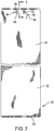
Figs. 4-6 each illustrate an exemplary alternative embodiment of a protrusion. -
Figs. 7-10 each illustrate an exemplary alternative embodiment of a protrusion that is not part of this invention. -
Fig. 11 generally illustrates the use of a flexible belt wrapper in combination with a continuous conveyor belt, the conveyor belt comprising a chain, wire or crossbar belt in combination with a contact toaster, according to one embodiment of this invention. -
Fig. 12 is a planar view of use of a belt wrapper according to another embodiment of this invention, having no lacing. -
Fig. 13 generally illustrates the connection of the belt wrapper ofFig. 12 to a metal link conveyor belt. - The present invention provides the use of a flexible belt wrapper in combination with a continuous conveyor belt, the conveyor belt comprising a chain, wire or crossbar belt. The belt wrapper is made of a flexible material, or a flexible coated and/or laminate material, and can be used as a conveyor belt alone or in combination with another conveyor belt. The flexible belt wrapper includes a connection element for connecting the flexible belt wrapper to an underlying conveyor belt, thereby providing a secure connection between the connected belts to allow the belts to travel together at the same speed without belt slippage. The belts of this invention can be used, for example, in the food industry in conjunction with high temperature food processing, ranging from about 148,89°C to 315,56°C (300°F to 600°F), and more preferable 260°C to 315,56°C (500°F to 600°F), at least for short durations.
-
Figs. 1-3 illustrate aflexible belt wrapper 30 to be used according to one embodiment of this invention, which includes aflexible substrate 32 having afirst face 34 and asecond face 36 that is opposite the first face. Theflexible substrate 32 can be formed from any suitable flexible conveyor belt material, such as fiberglass, nylon, polyester polyethylene, aramid, polyimide, polyphenylene sulfide, polyethersulfone, polyetheretherketone (PEET), or combinations thereof. The flexible substrate can be woven, nonwoven, or a film layer. - The
flexible belt wrapper 30 includes acoating 40 on at least thefirst face 34. The coating can be formed of one or more layers of suitable polymers. Exemplary coating polymers include fluoropolymers, such as a fluoroplastic or fiuoroelastomer, silicone rubbers, urethane rubbers, or combinations thereof. In one embodiment of this invention, the coating is tacky and/or can optionally include a plurality of flights orribs 42 raised above the coated face, in a regular, repeating, natural, random, or cyclical pattern, such as described inU.S. Patent 6,919,122 . Thesecond face 36 can include a coating and/or flights as well, and can be identical to or different from thefirst face 34. In one embodiment, theflexible substrate 32 is coated in the entirety, such as by dip-coating, and thecoating 40 is applied as a second or further coating on the coated flexible substrate. In one embodiment, the coating on thesecond face 36 is a sliding or non-tacky coating, having a low coefficient of friction to provide a sliding surface. It has been unexpectedly discovered that the non-tackysecond face 36 in combination with the protrusions of this invention, desirably reduces or eliminates belt gathering and/or "jumping" as the belt travels through the rollers of at least some types of cooking devices. - As shown in
Figs. 2 and3 , theflexible belt wrapper 30 includes twoprotrusions 46 attached to theflexible substrate 32. Each of theprotrusions 46 include anengagement surface 48 adapted to secure theprotrusion 46 to a portion of an underlying conveyor belt to drive the belt wrapper at a same speed as the conveyor belt. Theengagement surface 48 is disposed facing a direction that is parallel to thesecond face 34, and is designed to hook or otherwise hold onto a portion of the bottom conveyor belt. As shown in the embodiment ofFigs. 2 and3 , theengagement surface 48 has a curved and/or concave portion that can hook or clip onto a conveyor belt formed of or including a chain, wire, or crossbar. To accomplish a secure connection it is desirable that the engagement surface has a shape and/or curvature that correspondingly matches a curvature of a wire, crossbar, or other portion of the underlying conveyor belt. - In one embodiment of this invention, as shown in
Figs.2 and3 , theprotrusions 46 each include a second engagement surface 48' that faces an opposite direction from thefirst engagement surface 48. Theprotrusions 46 each include a base 50 that is fastened or otherwise attached to the flexible substrate, and the twoengagement surfaces 48 and 48' extend from opposing side edges of thebase 50. The protrusions inFigs. 2 and3 are thus embodied as a clip that secures, such as by a snap fitment, to or around two wires, crossbars, or other portions of the underlying conveyor belt. -
Figs. 4-6 illustrate, without limitation, various and alternative embodiments of a protrusion as in the use according to this invention andFigs. 7 to 10 illustrate alternative embodiments of a protrusion that are not part of the claimed invention.Fig.4 includes a single,longer clip 46 as an alternative to the two smaller, spaced-apart clips shown inFig. 2 .Fig. 5 illustrates an embodiment with twoclips 46 that each extends out from a side edge of thebelt 30 to clip onto the underlying conveyor belt or another conveyor device element.Fig. 6 illustrates ahook protrusion 46 with a curved or concave surface extending from only one side edge of a base fastened to the flexible substrate.Fig. 7 illustrates alug 46 that can include threads or other attachment element, such as a cotter pin.Fig. 8 illustrates anexemplary peg 46 that can be hooked or snapped onto wires or bars of a belt.Fig. 9 illustrates asnap protrusion 46 with a male portion on one of thebelt wrapper 30 or the underlying belt, and a female portion on the other of the belt wrapper or the underlying belt.Fig. 10 illustrates a hook andloop fastener protrusion 46, which is desirably a stainless steel hook and loop fastener. - The protrusion(s) can be formed of various and alternative materials, such as metal or a high-temperature resistant polymer.
- The protrusions can be molded to/from, adhered to, and/or mechanically fastened to the flexible substrate. As shown in
Fig. 2 , theprotrusions 46 are mechanically fastened byrivet 52 through an opening inbase 50. Other mechanical fastener possibilities include screws and bolts. -
Fig. 11 illustrates thebelt wrapper 30 in combination with a representatively showncontact toaster device 70. Thetoaster device 70 includes ahousing 72 with aninlet 74 for receiving thebun 76 halves to be toasted. - A
platen 80 is disposed through the middle ofhousing 72 and includes resistance heating elements so that its opposing surfaces are heated. To facilitate movement of thebun 76 acrossplaten 80, theplaten 80 surfaces should have smooth, non-stick surfaces. Twolink conveyor belts platen 80. Eachconveyor belt sprocket wheels 86. Each of theconveyor belts idler roller 88. One of thebelt wrapper 30 is secured around each of theconveyor belts coating 40 by material strip 62) by a pin, and with theclips 46 clipped onto twoadjacent cross-bars 85 of theconveyor belts bun 76 are placed into thetoaster 70 and pass along and againstplaten 80, propelled byconveyor belts overlying belt wrappers 30 moving without slipping at the same speed of thecorresponding conveyor belts Ribs 42 on thebelt wrapper 30 assist in movingbun 76 against theplaten 80. In one embodiment of this invention, theribs 42 are discontinuous as shown inFig. 1 , with aspacing 64 between a first plurality ofribs 66 on one side ofbelt 30 and a second plurality ofribs 68 on an opposing lateral side ofbelt 30. The spacing is provided, for example, to allow a smooth path for tensioningidle roller 88. -
Figs. 12 and 13 illustrate the use of a flexible belt wrapper in combination with a continuous conveyor belt, the conveyor belt comprising a chain, wire or crossbar belt according to another embodiment of the invention. Theflexible belt wrapper 130 includes aflexible substrate 132 having afirst face 134 and asecond face 136 that is opposite thefirst face 134. Theflexible belt wrapper 130 includes acoating 140, with or without ribs or flights, on thefirst face 134. The flexible substrate and coating can be formed as discussed above. Theflexible belt wrapper 130 includes a first set ofprotrusions 146 attached to afirst end 148 of theflexible substrate 132. Theflexible belt wrapper 130 further includes a second set ofprotrusions 150 attached to asecond end 152 of theflexible substrate 132. Theprotrusions Fig. 13 , each including two opposing curved engagement surfaces 154 that clip around two adjacent chains, wires, orcrossbars 160 of a representatively shown conveyor belt. Exemplary alternative clips for use as theprotrusions 146 and/or 150 include at least 2-4 longer dimensioned clips per belt end, such as shown inFigs. 14 and 15 , or the single clip extending across each belt end as shown inFig. 16 . - As shown in
Fig. 13 , theprotrusions leading end 148 adjacent to the trailingend 152 ofbelt 130 without the need for additional lacings, such as shown inFigs. 1-3 . Aflap 170 of material is sintered or otherwise attached to theflexible substrate 132 to cover the seam or spacing 172 between theleading edge 148 and trailingedge 152. This embodiment has particular advantage in making the belt wrapper easier and less time-consuming to apply to a conveyor belt. Also, in restaurant settings, the belt wrapper is typically changed by restaurant employees, and inserting the lacing pin can be difficult and, due to metal edges and hot cooking devices, has been known to cause minor injuries. - Thus, the invention provides the use of an improved belt wrapper with an enhanced connection to a metal wire or similar conveyor belt. The protrusions on the belt wrapper secure the belt wrapper and reduce or eliminate belt wrapper slipping on the metal belt, and keep the belt wrapper centered and properly tracking on the metal belt. The belt wrapper of this invention also facilitates easier and safer belt wrapper replacement.
- The invention illustratively disclosed herein suitably may be practiced in the absence of any element, part, step, component, or ingredient which is not specifically disclosed herein.
- While in the foregoing detailed description this invention has been described in relation to certain preferred embodiments thereof, and many details have been set forth for purposes of illustration, it will be apparent to those skilled in the art that the invention is susceptible to additional embodiments and that certain of the details described herein can be varied considerably without departing from the scope of the invention which is defined by the scope of the claims.
Claims (9)
- Use of a flexible belt wrapper (30, 130) in combination with a continuous conveyor belt (82, 84), the conveyor belt (82, 84) comprising a chain, wire or crossbar belt; the flexible belt wrapper comprising:
a flexible substrate (32, 132) having a first face (34, 134) and a second face (36, 136) opposite the first face (34, 134) that contacts the conveyor belt (82, 84); a coating (40) on the first face (34, 134) of the flexible substrate (32, 132) ; and a protrusion (46, 146, 150) attached to the second face (46, 146) of the flexible substrate (32, 132) and including an engagement surface (48, 154) adapted to secure the protrusion (46, 146, 150) to a portion of the conveyor belt (82, 84) to drive the belt wrapper (30, 130) at a same speed as the conveyor belt (82, 84), characterized in that the protrusion (46, 146, 150) is either embodied as a clip including a second engagement surface (48') that faces an opposite direction from the first engagement surface (48), each of the two engagement surfaces (48, 48') including a curved or concave surface, and a base (50) fastened to the second face (36, 136) of the flexible substrate (32, 132), and wherein the two engagement surfaces extend from opposing side edges of the base (50) so that said clip is securing by a snap fitment to or around two wires, crossbars or other portions of the underlying conveyor belt to drive the belt wrapper (30) at a same speed as the conveyor belt (82, 84), or the protrusion (46) comprises a base fastened to the second face (36, 136) of the flexible substrate (32, 132) and a hook protrusion with a curved or concave surface extending from only one side edge of the base, said hook protrusion being designed to hook onto a portion (160) of the conveyor belt (82, 84) to drive the belt wrapper (30) at a same speed as the conveyor belt (82, 84). - The use according to claim 1, characterized in that the flexible substrate (32, 132) comprises fiberglass, nylon, polyester polyethylene, aramid, polyimide, polyphenylene sulfide, polyethersulfone, polyetheretherketone (PEET), or combinations thereof and the coating (40) comprises a fluoroplastic, fluoroelastomer, silicone rubber, urethane rubber, or combinations thereof.
- The use according to claim 1 or 2, characterized in that the engagement surface (48) is disposed in a direction that is parallel to the second face (36, 136).
- The use according to one of the preceding claims, wherein the flexible belt wrapper (30, 130) includes a leading end (148) and a trailing end (152), the protrusion (146) is disposed at the leading end (148) to secure the leading end (148) to the conveyor belt (82, 84), and further comprising a second protrusion (150) attached to the flexible substrate (32, 132) at the trailing end (152) to secure the trailing end (152) to the conveyor belt (82, 84).
- The use according to one of the preceding claims, further comprising ribs (42, 66, 68) raised above the coating (40) on the first face (34, 134).
- The use according to Claim 5, wherein each of the ribs (42, 66, 68) is discontinuous across the first face (34, 134).
- The use according to one of the preceding claims, wherein the protrusion is attached to the flexible substrate (32, 132) by at least one mechanical fastener.
- The use according to one of the preceding claims, wherein the protrusion (46, 146, 150) comprises metal or a high-temperature resistant polymer.
- The use according to one of the preceding claims, in combination with a continuous wire belt of a cooking device, wherein the belt wrapper (30, 130) overlays the wire belt and the protrusion (46, 146, 150) is secured to a wire of the wire belt.
Priority Applications (1)
| Application Number | Priority Date | Filing Date | Title |
|---|---|---|---|
| PL13752253T PL2816938T3 (en) | 2012-02-24 | 2013-02-22 | Flexible conveyor belt wrapper |
Applications Claiming Priority (2)
| Application Number | Priority Date | Filing Date | Title |
|---|---|---|---|
| US201261603020P | 2012-02-24 | 2012-02-24 | |
| PCT/US2013/027344 WO2013126717A1 (en) | 2012-02-24 | 2013-02-22 | Flexible conveyor belt wrapper |
Publications (3)
| Publication Number | Publication Date |
|---|---|
| EP2816938A1 EP2816938A1 (en) | 2014-12-31 |
| EP2816938A4 EP2816938A4 (en) | 2015-12-30 |
| EP2816938B1 true EP2816938B1 (en) | 2018-08-01 |
Family
ID=49006243
Family Applications (1)
| Application Number | Title | Priority Date | Filing Date |
|---|---|---|---|
| EP13752253.8A Active EP2816938B1 (en) | 2012-02-24 | 2013-02-22 | Flexible conveyor belt wrapper |
Country Status (6)
| Country | Link |
|---|---|
| US (2) | US10308431B2 (en) |
| EP (1) | EP2816938B1 (en) |
| CA (1) | CA2864931C (en) |
| MX (1) | MX361854B (en) |
| PL (1) | PL2816938T3 (en) |
| WO (1) | WO2013126717A1 (en) |
Families Citing this family (8)
| Publication number | Priority date | Publication date | Assignee | Title |
|---|---|---|---|---|
| WO2013126717A1 (en) * | 2012-02-24 | 2013-08-29 | Advanced Flexible Composites, Inc. | Flexible conveyor belt wrapper |
| WO2014074242A1 (en) * | 2012-09-28 | 2014-05-15 | Btu International, Inc. | High temperature conveyor belt |
| GB2522884B (en) * | 2014-02-07 | 2018-06-20 | Blackman & White Ltd | Support surface for a cutting machine |
| CN104129594A (en) * | 2014-07-23 | 2014-11-05 | 安徽嘉木橡塑工业有限公司 | Fan-shaped pattern impact-resistant conveyer belt |
| WO2019067493A1 (en) * | 2017-09-28 | 2019-04-04 | Saint-Gobain Performance Plastics Corporation | Conveyor belt clip |
| WO2022120180A1 (en) * | 2020-12-03 | 2022-06-09 | Afc Specialty Coatings Group, Inc. | Non-stick belt with improved adhesion, puncture, conformability and flex properties |
| EP4408763A4 (en) * | 2021-10-01 | 2025-12-03 | Clayton Cooper | SYSTEM FOR THE MANUFACTURING OF PACKAGING MATERIAL |
| US20250072664A1 (en) * | 2023-08-30 | 2025-03-06 | Stearns Product Development Corporation | Contact toaster with belt |
Citations (1)
| Publication number | Priority date | Publication date | Assignee | Title |
|---|---|---|---|---|
| US3329256A (en) * | 1965-06-18 | 1967-07-04 | Belson Corp | Conveyor belt |
Family Cites Families (39)
| Publication number | Priority date | Publication date | Assignee | Title |
|---|---|---|---|---|
| DE179623C (en) | ||||
| US1493313A (en) | 1923-02-09 | 1924-05-06 | Young Joseph | Fastener for machine belts |
| GB310394A (en) | 1928-01-24 | 1929-04-24 | Harry Ewart Partridge | Improvements in conveyor belts |
| US2514429A (en) | 1945-06-27 | 1950-07-11 | Dayton Rubber Company | Double cog belt |
| US2459770A (en) * | 1945-09-06 | 1949-01-18 | Screw Conveyor Corp | Conveyer cover clamping and dustsealing means |
| US2718004A (en) * | 1953-09-21 | 1955-09-20 | Steinmetz Lawrence | Fastener applying machine |
| GB842859A (en) | 1955-12-08 | 1960-07-27 | Charrold Ltd | Improvements relating to belt conveyors |
| US3280847A (en) | 1961-09-19 | 1966-10-25 | Dow Chemical Co | Extrusion die |
| US3708382A (en) * | 1971-06-24 | 1973-01-02 | American Velcro Inc | Hooked surface of a hook and loop type fastener |
| DE2320921C3 (en) * | 1973-04-25 | 1979-10-18 | Draadindustrie Jonge Poerink B.V., Borne (Niederlande) | Link conveyor belt |
| US4282971A (en) * | 1979-10-05 | 1981-08-11 | Joy Manufacturing Company | Conveyor belt chain and method for its use |
| US4286870A (en) | 1980-01-10 | 1981-09-01 | Xerox Corporation | Document belt with discrete vacuum areas |
| JPS5842509A (en) | 1981-09-08 | 1983-03-12 | Nakura Seisakusho:Kk | Conveyer |
| US4541154A (en) * | 1981-11-12 | 1985-09-17 | Yoshida Kogyo K.K. | Hooked fabric fastener tape |
| US4922304A (en) | 1988-03-11 | 1990-05-01 | Imagitek | Reproduction machine fuser belt |
| US5232771A (en) * | 1991-09-12 | 1993-08-03 | Manville Corporation | Process for molding a fiberglass reinforced article |
| US5231738A (en) * | 1991-12-12 | 1993-08-03 | Kuraray Co., Ltd. | Mixed hook/loop separable fastener and process for its production |
| US5339499A (en) * | 1993-02-16 | 1994-08-23 | Velcro Industries B.V. | Hook design for a hook and loop fastener |
| US5586371A (en) * | 1994-11-08 | 1996-12-24 | The Procter & Gamble Company | Method for manufacturing refastenable fastening systems including a female loop fastening component and the product produced therefrom |
| US5588354A (en) | 1995-09-21 | 1996-12-31 | Marshall Air Systems, Inc. | Apparatus for conveyorized griddle-like cooking of food products |
| US5591796A (en) * | 1995-10-02 | 1997-01-07 | Rheox, Inc. | Pumpable anti-abrasion ink additives and printing inks containing such additives |
| US6329987B1 (en) * | 1996-12-09 | 2001-12-11 | Phil Gottfried | Lenticular image and method |
| US5960704A (en) * | 1998-01-29 | 1999-10-05 | A.J. Antunes & Co. | Contact toaster |
| US6035765A (en) | 1998-12-23 | 2000-03-14 | Welbilt Corporation | Conveyorized bun griller with non-marking belts |
| US6919122B2 (en) | 1999-07-08 | 2005-07-19 | Saint-Gobain Performance Plastics Corporation | Flexible composites with integral flights for use in high-temperature food processing equipment and methods for producing the same |
| US6352150B1 (en) | 2000-01-10 | 2002-03-05 | William J. Lewis | Coated endless belt |
| US6756327B2 (en) * | 2000-10-31 | 2004-06-29 | Kimberly-Clark Worldwide, Inc. | Loop fastening component made from thermally retracted materials |
| US6648127B2 (en) * | 2002-02-28 | 2003-11-18 | Joseph J. Molinaro | Conveyor belt with advertising and method of making same |
| US20030224137A1 (en) * | 2002-05-31 | 2003-12-04 | Han Bong Chung | Fastener and method of manufacturing the same |
| US7004311B2 (en) | 2003-01-31 | 2006-02-28 | Fenner U.S., Inc. | Non-slip conveyor and method for producing same |
| AU2003274825A1 (en) | 2003-10-23 | 2005-05-11 | Joan Anton Halbesma | Flexible conveyor for conveying exceptionally heavy loads |
| JP2006000703A (en) | 2004-06-15 | 2006-01-05 | Taiheiyo Cement Corp | Method of producing endless belt-like member, and belt-like member with hook and loop fastener |
| CN101115653A (en) * | 2004-12-17 | 2008-01-30 | 布兰顿·斯蒂尔·约翰斯顿 | conveyor belt covering |
| PL1838600T3 (en) * | 2005-01-19 | 2012-01-31 | Thermodrive Llc | Low friction, direct drive conveyor belt |
| US8025144B2 (en) | 2005-02-11 | 2011-09-27 | Advanced Flexible Composites, Inc. | Conveyor belts with thin film sensor-activating coating |
| DE102006015100B4 (en) * | 2006-03-31 | 2008-04-30 | Reinz-Dichtungs-Gmbh | mounting device |
| US7493676B2 (en) * | 2006-04-13 | 2009-02-24 | Ykk Corporation | Hook fastener structures |
| US9174142B2 (en) * | 2010-03-19 | 2015-11-03 | Hyung-Gon Lee | Fastening structure |
| WO2013126717A1 (en) * | 2012-02-24 | 2013-08-29 | Advanced Flexible Composites, Inc. | Flexible conveyor belt wrapper |
-
2013
- 2013-02-22 WO PCT/US2013/027344 patent/WO2013126717A1/en not_active Ceased
- 2013-02-22 CA CA2864931A patent/CA2864931C/en active Active
- 2013-02-22 EP EP13752253.8A patent/EP2816938B1/en active Active
- 2013-02-22 MX MX2014010062A patent/MX361854B/en active IP Right Grant
- 2013-02-22 US US13/774,283 patent/US10308431B2/en active Active
- 2013-02-22 PL PL13752253T patent/PL2816938T3/en unknown
-
2017
- 2017-09-13 US US15/703,425 patent/US10611573B2/en active Active
Patent Citations (1)
| Publication number | Priority date | Publication date | Assignee | Title |
|---|---|---|---|---|
| US3329256A (en) * | 1965-06-18 | 1967-07-04 | Belson Corp | Conveyor belt |
Also Published As
| Publication number | Publication date |
|---|---|
| US10308431B2 (en) | 2019-06-04 |
| EP2816938A4 (en) | 2015-12-30 |
| CA2864931A1 (en) | 2013-08-29 |
| PL2816938T3 (en) | 2018-12-31 |
| MX361854B (en) | 2018-12-18 |
| US10611573B2 (en) | 2020-04-07 |
| CA2864931C (en) | 2019-11-12 |
| WO2013126717A1 (en) | 2013-08-29 |
| US20180065810A1 (en) | 2018-03-08 |
| EP2816938A1 (en) | 2014-12-31 |
| MX2014010062A (en) | 2015-03-06 |
| US20130240333A1 (en) | 2013-09-19 |
Similar Documents
| Publication | Publication Date | Title |
|---|---|---|
| US10611573B2 (en) | Toaster with conveyor and belt wrapper | |
| US9481522B2 (en) | Conveyors and transmission belts | |
| US10273089B2 (en) | Conveyor belt slat | |
| JP2009525243A (en) | Conveyor with trough-type low friction positive drive belt | |
| US7284657B2 (en) | Modular conveyor belt with unique link capture means | |
| US9908708B1 (en) | Conveyor belt link with coupling mechanism | |
| US9694979B2 (en) | Plate conveyor belt | |
| US20080135383A1 (en) | Gapless side guard | |
| US20220144553A1 (en) | Modular link conveyor with features for enhancing the efficient conveyance of articles | |
| MXPA06004080A (en) | Side-flexing conveyor chain having twin transverse connectors. | |
| US11724886B2 (en) | Safety device for push conveyor | |
| CA3017516C (en) | Apparatus and method for driving low coefficient of friction belting | |
| US20110168527A1 (en) | Multi-belt conveyor having link belts | |
| US10696482B2 (en) | Modular link conveyor with features for enhancing efficient article conveyance | |
| WO2007076532A2 (en) | Composite conveyor with serrated intermediate links | |
| WO2007085446A1 (en) | Conveyor belt system, and device for preparation of food comprising such a conveyor belt system | |
| US20180178983A1 (en) | Flights and fasteners for compact-grid conveyor belts | |
| EP3494074B1 (en) | Conveyor section | |
| CN118302614A (en) | Fastening systems for conveyor belts | |
| EP1532061A1 (en) | Conveyor | |
| JPH0638013Y2 (en) | Article conveyor with toothed belt | |
| CA3198101A1 (en) | Non-stick belt with improved adhesion, puncture, conformability and flex properties |
Legal Events
| Date | Code | Title | Description |
|---|---|---|---|
| PUAI | Public reference made under article 153(3) epc to a published international application that has entered the european phase |
Free format text: ORIGINAL CODE: 0009012 |
|
| 17P | Request for examination filed |
Effective date: 20140827 |
|
| AK | Designated contracting states |
Kind code of ref document: A1 Designated state(s): AL AT BE BG CH CY CZ DE DK EE ES FI FR GB GR HR HU IE IS IT LI LT LU LV MC MK MT NL NO PL PT RO RS SE SI SK SM TR |
|
| AX | Request for extension of the european patent |
Extension state: BA ME |
|
| DAX | Request for extension of the european patent (deleted) | ||
| RA4 | Supplementary search report drawn up and despatched (corrected) |
Effective date: 20151201 |
|
| RIC1 | Information provided on ipc code assigned before grant |
Ipc: A47J 37/08 20060101AFI20151125BHEP Ipc: B65G 15/32 20060101ALI20151125BHEP Ipc: B65G 15/30 20060101ALI20151125BHEP Ipc: A21B 1/46 20060101ALI20151125BHEP Ipc: B65G 23/14 20060101ALI20151125BHEP Ipc: B65G 15/56 20060101ALI20151125BHEP |
|
| STAA | Information on the status of an ep patent application or granted ep patent |
Free format text: STATUS: EXAMINATION IS IN PROGRESS |
|
| 17Q | First examination report despatched |
Effective date: 20161209 |
|
| GRAP | Despatch of communication of intention to grant a patent |
Free format text: ORIGINAL CODE: EPIDOSNIGR1 |
|
| STAA | Information on the status of an ep patent application or granted ep patent |
Free format text: STATUS: GRANT OF PATENT IS INTENDED |
|
| INTG | Intention to grant announced |
Effective date: 20180321 |
|
| GRAS | Grant fee paid |
Free format text: ORIGINAL CODE: EPIDOSNIGR3 |
|
| GRAA | (expected) grant |
Free format text: ORIGINAL CODE: 0009210 |
|
| STAA | Information on the status of an ep patent application or granted ep patent |
Free format text: STATUS: THE PATENT HAS BEEN GRANTED |
|
| AK | Designated contracting states |
Kind code of ref document: B1 Designated state(s): AL AT BE BG CH CY CZ DE DK EE ES FI FR GB GR HR HU IE IS IT LI LT LU LV MC MK MT NL NO PL PT RO RS SE SI SK SM TR |
|
| REG | Reference to a national code |
Ref country code: GB Ref legal event code: FG4D |
|
| REG | Reference to a national code |
Ref country code: AT Ref legal event code: REF Ref document number: 1023317 Country of ref document: AT Kind code of ref document: T Effective date: 20180815 Ref country code: CH Ref legal event code: EP |
|
| REG | Reference to a national code |
Ref country code: IE Ref legal event code: FG4D |
|
| REG | Reference to a national code |
Ref country code: DE Ref legal event code: R096 Ref document number: 602013041213 Country of ref document: DE |
|
| REG | Reference to a national code |
Ref country code: NL Ref legal event code: FP |
|
| REG | Reference to a national code |
Ref country code: SE Ref legal event code: TRGR |
|
| REG | Reference to a national code |
Ref country code: LT Ref legal event code: MG4D |
|
| REG | Reference to a national code |
Ref country code: AT Ref legal event code: MK05 Ref document number: 1023317 Country of ref document: AT Kind code of ref document: T Effective date: 20180801 |
|
| PG25 | Lapsed in a contracting state [announced via postgrant information from national office to epo] |
Ref country code: AT Free format text: LAPSE BECAUSE OF FAILURE TO SUBMIT A TRANSLATION OF THE DESCRIPTION OR TO PAY THE FEE WITHIN THE PRESCRIBED TIME-LIMIT Effective date: 20180801 Ref country code: IS Free format text: LAPSE BECAUSE OF FAILURE TO SUBMIT A TRANSLATION OF THE DESCRIPTION OR TO PAY THE FEE WITHIN THE PRESCRIBED TIME-LIMIT Effective date: 20181201 Ref country code: GR Free format text: LAPSE BECAUSE OF FAILURE TO SUBMIT A TRANSLATION OF THE DESCRIPTION OR TO PAY THE FEE WITHIN THE PRESCRIBED TIME-LIMIT Effective date: 20181102 Ref country code: NO Free format text: LAPSE BECAUSE OF FAILURE TO SUBMIT A TRANSLATION OF THE DESCRIPTION OR TO PAY THE FEE WITHIN THE PRESCRIBED TIME-LIMIT Effective date: 20181101 Ref country code: BG Free format text: LAPSE BECAUSE OF FAILURE TO SUBMIT A TRANSLATION OF THE DESCRIPTION OR TO PAY THE FEE WITHIN THE PRESCRIBED TIME-LIMIT Effective date: 20181101 Ref country code: FI Free format text: LAPSE BECAUSE OF FAILURE TO SUBMIT A TRANSLATION OF THE DESCRIPTION OR TO PAY THE FEE WITHIN THE PRESCRIBED TIME-LIMIT Effective date: 20180801 Ref country code: RS Free format text: LAPSE BECAUSE OF FAILURE TO SUBMIT A TRANSLATION OF THE DESCRIPTION OR TO PAY THE FEE WITHIN THE PRESCRIBED TIME-LIMIT Effective date: 20180801 Ref country code: LT Free format text: LAPSE BECAUSE OF FAILURE TO SUBMIT A TRANSLATION OF THE DESCRIPTION OR TO PAY THE FEE WITHIN THE PRESCRIBED TIME-LIMIT Effective date: 20180801 |
|
| PG25 | Lapsed in a contracting state [announced via postgrant information from national office to epo] |
Ref country code: LV Free format text: LAPSE BECAUSE OF FAILURE TO SUBMIT A TRANSLATION OF THE DESCRIPTION OR TO PAY THE FEE WITHIN THE PRESCRIBED TIME-LIMIT Effective date: 20180801 Ref country code: HR Free format text: LAPSE BECAUSE OF FAILURE TO SUBMIT A TRANSLATION OF THE DESCRIPTION OR TO PAY THE FEE WITHIN THE PRESCRIBED TIME-LIMIT Effective date: 20180801 Ref country code: AL Free format text: LAPSE BECAUSE OF FAILURE TO SUBMIT A TRANSLATION OF THE DESCRIPTION OR TO PAY THE FEE WITHIN THE PRESCRIBED TIME-LIMIT Effective date: 20180801 |
|
| PG25 | Lapsed in a contracting state [announced via postgrant information from national office to epo] |
Ref country code: RO Free format text: LAPSE BECAUSE OF FAILURE TO SUBMIT A TRANSLATION OF THE DESCRIPTION OR TO PAY THE FEE WITHIN THE PRESCRIBED TIME-LIMIT Effective date: 20180801 Ref country code: CZ Free format text: LAPSE BECAUSE OF FAILURE TO SUBMIT A TRANSLATION OF THE DESCRIPTION OR TO PAY THE FEE WITHIN THE PRESCRIBED TIME-LIMIT Effective date: 20180801 Ref country code: EE Free format text: LAPSE BECAUSE OF FAILURE TO SUBMIT A TRANSLATION OF THE DESCRIPTION OR TO PAY THE FEE WITHIN THE PRESCRIBED TIME-LIMIT Effective date: 20180801 Ref country code: ES Free format text: LAPSE BECAUSE OF FAILURE TO SUBMIT A TRANSLATION OF THE DESCRIPTION OR TO PAY THE FEE WITHIN THE PRESCRIBED TIME-LIMIT Effective date: 20180801 |
|
| REG | Reference to a national code |
Ref country code: DE Ref legal event code: R097 Ref document number: 602013041213 Country of ref document: DE |
|
| PG25 | Lapsed in a contracting state [announced via postgrant information from national office to epo] |
Ref country code: SM Free format text: LAPSE BECAUSE OF FAILURE TO SUBMIT A TRANSLATION OF THE DESCRIPTION OR TO PAY THE FEE WITHIN THE PRESCRIBED TIME-LIMIT Effective date: 20180801 Ref country code: DK Free format text: LAPSE BECAUSE OF FAILURE TO SUBMIT A TRANSLATION OF THE DESCRIPTION OR TO PAY THE FEE WITHIN THE PRESCRIBED TIME-LIMIT Effective date: 20180801 Ref country code: SK Free format text: LAPSE BECAUSE OF FAILURE TO SUBMIT A TRANSLATION OF THE DESCRIPTION OR TO PAY THE FEE WITHIN THE PRESCRIBED TIME-LIMIT Effective date: 20180801 |
|
| PLBE | No opposition filed within time limit |
Free format text: ORIGINAL CODE: 0009261 |
|
| STAA | Information on the status of an ep patent application or granted ep patent |
Free format text: STATUS: NO OPPOSITION FILED WITHIN TIME LIMIT |
|
| 26N | No opposition filed |
Effective date: 20190503 |
|
| PG25 | Lapsed in a contracting state [announced via postgrant information from national office to epo] |
Ref country code: SI Free format text: LAPSE BECAUSE OF FAILURE TO SUBMIT A TRANSLATION OF THE DESCRIPTION OR TO PAY THE FEE WITHIN THE PRESCRIBED TIME-LIMIT Effective date: 20180801 |
|
| REG | Reference to a national code |
Ref country code: CH Ref legal event code: PL |
|
| PG25 | Lapsed in a contracting state [announced via postgrant information from national office to epo] |
Ref country code: LU Free format text: LAPSE BECAUSE OF NON-PAYMENT OF DUE FEES Effective date: 20190222 Ref country code: MC Free format text: LAPSE BECAUSE OF FAILURE TO SUBMIT A TRANSLATION OF THE DESCRIPTION OR TO PAY THE FEE WITHIN THE PRESCRIBED TIME-LIMIT Effective date: 20180801 |
|
| REG | Reference to a national code |
Ref country code: BE Ref legal event code: MM Effective date: 20190228 |
|
| PG25 | Lapsed in a contracting state [announced via postgrant information from national office to epo] |
Ref country code: CH Free format text: LAPSE BECAUSE OF NON-PAYMENT OF DUE FEES Effective date: 20190228 Ref country code: LI Free format text: LAPSE BECAUSE OF NON-PAYMENT OF DUE FEES Effective date: 20190228 |
|
| PG25 | Lapsed in a contracting state [announced via postgrant information from national office to epo] |
Ref country code: BE Free format text: LAPSE BECAUSE OF NON-PAYMENT OF DUE FEES Effective date: 20190228 |
|
| PG25 | Lapsed in a contracting state [announced via postgrant information from national office to epo] |
Ref country code: TR Free format text: LAPSE BECAUSE OF FAILURE TO SUBMIT A TRANSLATION OF THE DESCRIPTION OR TO PAY THE FEE WITHIN THE PRESCRIBED TIME-LIMIT Effective date: 20180801 |
|
| PGFP | Annual fee paid to national office [announced via postgrant information from national office to epo] |
Ref country code: IE Payment date: 20200219 Year of fee payment: 8 Ref country code: SE Payment date: 20200224 Year of fee payment: 8 Ref country code: IT Payment date: 20200221 Year of fee payment: 8 |
|
| PG25 | Lapsed in a contracting state [announced via postgrant information from national office to epo] |
Ref country code: PT Free format text: LAPSE BECAUSE OF FAILURE TO SUBMIT A TRANSLATION OF THE DESCRIPTION OR TO PAY THE FEE WITHIN THE PRESCRIBED TIME-LIMIT Effective date: 20181201 Ref country code: MT Free format text: LAPSE BECAUSE OF NON-PAYMENT OF DUE FEES Effective date: 20190222 |
|
| PGFP | Annual fee paid to national office [announced via postgrant information from national office to epo] |
Ref country code: NL Payment date: 20210218 Year of fee payment: 9 Ref country code: FR Payment date: 20210217 Year of fee payment: 9 |
|
| PG25 | Lapsed in a contracting state [announced via postgrant information from national office to epo] |
Ref country code: CY Free format text: LAPSE BECAUSE OF FAILURE TO SUBMIT A TRANSLATION OF THE DESCRIPTION OR TO PAY THE FEE WITHIN THE PRESCRIBED TIME-LIMIT Effective date: 20180801 |
|
| PG25 | Lapsed in a contracting state [announced via postgrant information from national office to epo] |
Ref country code: HU Free format text: LAPSE BECAUSE OF FAILURE TO SUBMIT A TRANSLATION OF THE DESCRIPTION OR TO PAY THE FEE WITHIN THE PRESCRIBED TIME-LIMIT; INVALID AB INITIO Effective date: 20130222 |
|
| REG | Reference to a national code |
Ref country code: SE Ref legal event code: EUG |
|
| PG25 | Lapsed in a contracting state [announced via postgrant information from national office to epo] |
Ref country code: SE Free format text: LAPSE BECAUSE OF NON-PAYMENT OF DUE FEES Effective date: 20210223 |
|
| PG25 | Lapsed in a contracting state [announced via postgrant information from national office to epo] |
Ref country code: IE Free format text: LAPSE BECAUSE OF NON-PAYMENT OF DUE FEES Effective date: 20210222 |
|
| PG25 | Lapsed in a contracting state [announced via postgrant information from national office to epo] |
Ref country code: IT Free format text: LAPSE BECAUSE OF NON-PAYMENT OF DUE FEES Effective date: 20210222 |
|
| PG25 | Lapsed in a contracting state [announced via postgrant information from national office to epo] |
Ref country code: MK Free format text: LAPSE BECAUSE OF FAILURE TO SUBMIT A TRANSLATION OF THE DESCRIPTION OR TO PAY THE FEE WITHIN THE PRESCRIBED TIME-LIMIT Effective date: 20180801 |
|
| REG | Reference to a national code |
Ref country code: NL Ref legal event code: MM Effective date: 20220301 |
|
| PG25 | Lapsed in a contracting state [announced via postgrant information from national office to epo] |
Ref country code: NL Free format text: LAPSE BECAUSE OF NON-PAYMENT OF DUE FEES Effective date: 20220301 Ref country code: FR Free format text: LAPSE BECAUSE OF NON-PAYMENT OF DUE FEES Effective date: 20220228 |
|
| P01 | Opt-out of the competence of the unified patent court (upc) registered |
Effective date: 20230522 |
|
| REG | Reference to a national code |
Ref country code: DE Ref legal event code: R082 Ref document number: 602013041213 Country of ref document: DE Representative=s name: KBN IP PATENTANWAELTE PARTNERSCHAFT MBB, DE |
|
| PGFP | Annual fee paid to national office [announced via postgrant information from national office to epo] |
Ref country code: PL Payment date: 20250307 Year of fee payment: 13 |
|
| PGFP | Annual fee paid to national office [announced via postgrant information from national office to epo] |
Ref country code: GB Payment date: 20260317 Year of fee payment: 14 |
|
| PGFP | Annual fee paid to national office [announced via postgrant information from national office to epo] |
Ref country code: DE Payment date: 20260224 Year of fee payment: 14 |