EP2816698A1 - Systems and methods for tuning the control of a shunt active power filter over a variable frequency - Google Patents
Systems and methods for tuning the control of a shunt active power filter over a variable frequency Download PDFInfo
- Publication number
- EP2816698A1 EP2816698A1 EP14173260.2A EP14173260A EP2816698A1 EP 2816698 A1 EP2816698 A1 EP 2816698A1 EP 14173260 A EP14173260 A EP 14173260A EP 2816698 A1 EP2816698 A1 EP 2816698A1
- Authority
- EP
- European Patent Office
- Prior art keywords
- power signal
- harmonics
- active power
- source power
- shunt active
- Prior art date
- Legal status (The legal status is an assumption and is not a legal conclusion. Google has not performed a legal analysis and makes no representation as to the accuracy of the status listed.)
- Granted
Links
Images

Classifications
-
- H—ELECTRICITY
- H02—GENERATION; CONVERSION OR DISTRIBUTION OF ELECTRIC POWER
- H02J—ELECTRIC POWER NETWORKS; CIRCUIT ARRANGEMENTS OR SYSTEMS FOR SUPPLYING OR DISTRIBUTING ELECTRIC POWER; SYSTEMS FOR STORING ELECTRIC ENERGY
- H02J3/00—Circuit arrangements for AC mains or AC distribution networks
- H02J3/01—Arrangements for reducing harmonics or ripples
-
- Y—GENERAL TAGGING OF NEW TECHNOLOGICAL DEVELOPMENTS; GENERAL TAGGING OF CROSS-SECTIONAL TECHNOLOGIES SPANNING OVER SEVERAL SECTIONS OF THE IPC; TECHNICAL SUBJECTS COVERED BY FORMER USPC CROSS-REFERENCE ART COLLECTIONS [XRACs] AND DIGESTS
- Y02—TECHNOLOGIES OR APPLICATIONS FOR MITIGATION OR ADAPTATION AGAINST CLIMATE CHANGE
- Y02E—REDUCTION OF GREENHOUSE GAS [GHG] EMISSIONS, RELATED TO ENERGY GENERATION, TRANSMISSION OR DISTRIBUTION
- Y02E40/00—Technologies for an efficient electrical power generation, transmission or distribution
- Y02E40/20—Active power filtering [APF]
Definitions
- the present teachings relate to systems and methods for tuning the control of a shunt active power filter over a variable frequency, and more particularly, to platforms and techniques for tuning the harmonic values which are dampened in a shunt active power filter using selectable feedback gain over variable source frequencies.
- a rectifier connected to a 3-phase AC voltage source generates undesired current harmonics, which can include at least the 5th, 7th, 11th, 13th, 17th, and 19 th harmonics, which can introduce noise and other artifacts in the power circuit.
- a shunt active power filter designed to operate on source voltages which are variable, such as between 360-800 Hz.
- source voltages which are variable, such as between 360-800 Hz
- the range and amplitude of potential harmonics of the source current can be significant. Providing a way to selectively tune to, and dampen, those harmonics has not been established.
- Embodiments of the present teachings relate to systems and methods for tuning the control of a shunt active power filter over a variable frequency. More particularly, embodiments relate to platforms and techniques for introducing a shunt active power filter to a power supply network.
- the shunt active power filter can be configured to selectively target undesirable harmonics generated over a variable frequency range in an alternating power source.
- the shunt active power filter can employ a set of resonant regulators in a parallel or stacked arrangement, which each resonant regulator tuned to a particular harmonic over the desired or target frequency range of the power source.
- FIG. 1 illustrates an overall shunt active power filter system 100 which can be used as a component in which systems and methods for tuning the control of a shunt active power filter over a variable frequency can operate, according to aspects.
- the system 100 can generally include a voltage source 102 coupled to an inductor element 104 through which a source current (Is) flows.
- the voltage source 102 can be or include a three-phase voltage or other power source.
- the voltage source can be coupled at voltage Vpcc to a load 106 and a network 108 to produce filtering effects.
- the load 106 can receive a load current (IL), and as shown, include a set of inductive, resistive, and capacitive elements to permit tuneability or adjustability to various frequencies.
- IL load current
- the network 108 can receive a filter current (If) and provide an output voltage (Vdc) which can be supplied to the load 106, such as a motorized load or other load.
- a filter current If
- Vdc output voltage
- two or more elements similar to that of system 100 can be incorporated in an overall shunt active power filter having multiple tuned frequencies, to permit the selective damping of particular harmonics and/or frequencies.
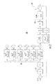
- an overall system 200 can receive a source voltage (not shown), and couple the source voltage and/or current to a set of resonant regulators 202.
- Each of the set of resonant regulators can be configured to operate at a particular harmonic of the source voltage or current.
- those harmonics can be or include the 5 th , 7 th , 11 th , 13 th , 17 th , and 19 th harmonics, but it will be appreciated that other harmonics can be used in addition to or instead of those illustrated.
- a local gain value (k5, k7, etc.) can be set to 1 for each resonant regulator, the outputs of which are summed and coupled to a plant 204 having a characteristic function (1/(LS +R)).
- a current output is produced at 208, which is coupled to the set of resonant regulators 202 via a gain value 206 at a sum point 210.
- the overall system 200 allows for harmonic control of output current by tuning the gain value 206 (K).
- the chosen gain value 206 (K) will determine how fast the set of resonant regulators 202 will eliminate the harmonics in multiples of the fundamental frequency, for a given source current frequency.
- the source current frequency can, again, be selected in the range of 360 - 800 Hz, although other ranges can be used.
- the root locus technique can be used to observe the closed loop poles of the overall system 200 as K varies from zero to infinity (or an arbitrarily large number).
- the root locus behavior can be generated and/or observed using, for instance, conventional software applications which calculate and plot the poles of a transfer function behavior, as a function of gain or other variables. Values of K which target the desired source harmonics by creating a notch filter at those harmonic frequencies, as a function of current source frequency, can be selected.
Landscapes
- Engineering & Computer Science (AREA)
- Power Engineering (AREA)
- Supply And Distribution Of Alternating Current (AREA)
- Inverter Devices (AREA)
Abstract
Description
- The present teachings relate to systems and methods for tuning the control of a shunt active power filter over a variable frequency, and more particularly, to platforms and techniques for tuning the harmonic values which are dampened in a shunt active power filter using selectable feedback gain over variable source frequencies.
- In the field of power systems, it has been known to connect a rectifier to an alternating current (AC) power source to derive a direct current (DC) for motors or other loads. A rectifier connected to a 3-phase AC voltage source, however, generates undesired current harmonics, which can include at least the 5th, 7th, 11th, 13th, 17th, and 19th harmonics, which can introduce noise and other artifacts in the power circuit.
- To address that undesirable harmonic content, it has been known to use a shunt active power filter.
- Moreover, the application of a shunt active power filter to a variable frequency system has not been demonstrated. In a shunt active power filter designed to operate on source voltages which are variable, such as between 360-800 Hz, the range and amplitude of potential harmonics of the source current can be significant. Providing a way to selectively tune to, and dampen, those harmonics has not been established.
- It may be desirable to provide methods and systems for tuning the control of a shunt active power filter over a variable frequency, in which harmonics generated at any point over a range of power source frequencies can be selectively tuned-for and dampened to prevent spurious output voltages to loads..
- The accompanying drawings, which are incorporated in and constitute a part of this specification, illustrate embodiments of the present teachings and together with the description, serve to explain the principles of the present teachings. In the figures:
-
FIG. 1 illustrates a shunt active power filter, according to various embodiments; -
FIG. 2 illustrates an overall active power filter system consistent with systems and methods for tuning the control of a shunt active power filter over a variable frequency, according to various embodiments; and -
FIG. 3 illustrates a Bode diagram of certain output characteristics of systems and methods for tuning the control of a shunt active power filter over a variable frequency, according to various aspects. - Embodiments of the present teachings relate to systems and methods for tuning the control of a shunt active power filter over a variable frequency. More particularly, embodiments relate to platforms and techniques for introducing a shunt active power filter to a power supply network. In aspects, the shunt active power filter can be configured to selectively target undesirable harmonics generated over a variable frequency range in an alternating power source. According to aspects, the shunt active power filter can employ a set of resonant regulators in a parallel or stacked arrangement, which each resonant regulator tuned to a particular harmonic over the desired or target frequency range of the power source.
- Reference will now be made in detail to exemplary embodiments of the present teachings, which are illustrated in the accompanying drawings. Where possible the same reference numbers will be used throughout the drawings to refer to the same or like parts.
-
FIG. 1 illustrates an overall shunt active power filter system 100 which can be used as a component in which systems and methods for tuning the control of a shunt active power filter over a variable frequency can operate, according to aspects. In aspects as shown, the system 100 can generally include avoltage source 102 coupled to aninductor element 104 through which a source current (Is) flows. In implementations, thevoltage source 102 can be or include a three-phase voltage or other power source. The voltage source can be coupled at voltage Vpcc to aload 106 and anetwork 108 to produce filtering effects. Theload 106 can receive a load current (IL), and as shown, include a set of inductive, resistive, and capacitive elements to permit tuneability or adjustability to various frequencies. Thenetwork 108 can receive a filter current (If) and provide an output voltage (Vdc) which can be supplied to theload 106, such as a motorized load or other load. In implementations, two or more elements similar to that of system 100 can be incorporated in an overall shunt active power filter having multiple tuned frequencies, to permit the selective damping of particular harmonics and/or frequencies. - More specifically and as for instance illustrated in
FIG. 2 , anoverall system 200 according to aspects of the present teachings can receive a source voltage (not shown), and couple the source voltage and/or current to a set ofresonant regulators 202. Each of the set of resonant regulators can be configured to operate at a particular harmonic of the source voltage or current. In implementations as shown, those harmonics can be or include the 5th, 7th, 11th, 13th, 17th, and 19th harmonics, but it will be appreciated that other harmonics can be used in addition to or instead of those illustrated. According to aspects, a local gain value (k5, k7, etc.) can be set to 1 for each resonant regulator, the outputs of which are summed and coupled to aplant 204 having a characteristic function (1/(LS +R)). A current output is produced at 208, which is coupled to the set ofresonant regulators 202 via again value 206 at a sum point 210. - In implementations, the
overall system 200 allows for harmonic control of output current by tuning the gain value 206 (K). The chosen gain value 206 (K) will determine how fast the set ofresonant regulators 202 will eliminate the harmonics in multiples of the fundamental frequency, for a given source current frequency. The source current frequency can, again, be selected in the range of 360 - 800 Hz, although other ranges can be used. In terms of damping effect, if thegain value 206 or K = ½, then the harmonics will be eliminated in about two fundamental periods. According to aspects, in order to set the value of K, the root locus technique can be used to observe the closed loop poles of theoverall system 200 as K varies from zero to infinity (or an arbitrarily large number). The root locus behavior can be generated and/or observed using, for instance, conventional software applications which calculate and plot the poles of a transfer function behavior, as a function of gain or other variables. Values of K which target the desired source harmonics by creating a notch filter at those harmonic frequencies, as a function of current source frequency, can be selected. - As a result, and as for example shown in the Bode diagram of
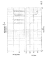
FIG. 3 , a characteristic behavior of the source current (Is) divided by the load current (IL) as a complex function of (s) is achieved, in which that function exhibits notch filter behavior corresponding to selected harmonic frequencies (again, which can include odd harmonics such as the 5th, 7th, 11th, 13th, 17th and 19th. Phase effects as shown are also produced - The foregoing description is illustrative, and variations in configuration and implementation may occur to persons skilled in the art. As noted, while the set of
resonant regulators 202 has been described in terms of a set of regulators tuned to the 5th, 7th, 11th, 13th, 17th and 19th harmonics, again other harmonics can be used instead of, or in addition to, those harmonics. For further example, while embodiments have been described in which one output voltage is produced, in implementations, multiple voltage outputs, which can be of different values, can be produced. Other resources described as singular or integrated can in embodiments be plural or distributed, and resources described as multiple or distributed can in embodiments be combined. The scope of the present teachings is accordingly intended to be limited only by the following claims.
Claims (15)
- A shunt active power filter system, comprising:a first interface to a source power signal having a selectable frequency;a set of resonant regulators coupled to the source power signal;a second interface configured to couple an output power signal from the set of resonant regulators to a load;a feedback loop, coupled between the source power signal and the set of resonant regulators, having a selectable gain value;wherein the selectable gain value is selected to dampen a set of harmonics associated with the source power signal at a selected frequency based on a set of closed loop poles of the shunt active power filter system associated with the selected gain value.
- The system of claim 1, wherein the source power signal comprises an alternating current signal.
- The system of claim 2, wherein a frequency of the source power signal comprises a range of 360 to 800 Hz.
- The system of claim 3, wherein the set of harmonics comprises at least a set of 5th, 7th, 11th, 13th, 17th, and 19th harmonics.
- The system of claim 1, wherein the set of resonant regulators are connected in a parallel configuration.
- The system of claim 1, wherein the load comprises a rectified load.
- The system of claim 1, wherein the selectable gain value determines a rate of decay of the set of harmonics.
- The system of claim 7, wherein the rate of decay is at least approximately equal to an inverse of the gain multiplied by a fundamental period of the source power signal.
- A method of generating a power signal, comprising:receiving a source power signal in a shunt active power filter;coupling the source power signal to a set of resonant regulators;coupling an output power signal from the set of resonant regulators to a load;coupling the output power signal to the set of resonant regulators via a feedback loop having a selectable gain value;selecting a frequency of the source power signal;selecting the selectable gain value to dampen a set of harmonics associated with the source power signal at the selected frequency based on a set of closed loop poles of the shunt active power filter associated with the selected gain value.
- The method of claim 9, wherein the source power signal comprises an alternating current signal.
- The method of claim 10, wherein a frequency of the source power signal comprises a range of 360 to 800 Hz.
- The method of claim 11, wherein the set of harmonics comprises at least a set of 5th, 7th, 11th, 13th, 17th, and 19th harmonics.
- The method of claim 9, wherein the set of resonant regulators are connected in a parallel configuration.
- The method of claim 9, wherein the load comprises a rectified load
- The method of claim 9, wherein the selectable gain value determines a rate of decay of the set of harmonics.
Applications Claiming Priority (1)
| Application Number | Priority Date | Filing Date | Title |
|---|---|---|---|
| US13/923,807 US9225172B2 (en) | 2013-06-21 | 2013-06-21 | Systems and methods for tuning the control of a shunt active power filter over a variable frequency |
Publications (2)
| Publication Number | Publication Date |
|---|---|
| EP2816698A1 true EP2816698A1 (en) | 2014-12-24 |
| EP2816698B1 EP2816698B1 (en) | 2019-05-15 |
Family
ID=51022742
Family Applications (1)
| Application Number | Title | Priority Date | Filing Date |
|---|---|---|---|
| EP14173260.2A Active EP2816698B1 (en) | 2013-06-21 | 2014-06-20 | Systems and methods for tuning the control of a shunt active power filter over a variable frequency |
Country Status (2)
| Country | Link |
|---|---|
| US (1) | US9225172B2 (en) |
| EP (1) | EP2816698B1 (en) |
Cited By (2)
| Publication number | Priority date | Publication date | Assignee | Title |
|---|---|---|---|---|
| CN107623450A (en) * | 2017-05-22 | 2018-01-23 | 北方工业大学 | A dual-frequency single-phase PWM rectifier |
| CN113629730A (en) * | 2021-07-29 | 2021-11-09 | 西南交通大学 | Harmonic power adjustment-based low-frequency oscillation suppression method for high-speed rail car network coupling system |
Families Citing this family (2)
| Publication number | Priority date | Publication date | Assignee | Title |
|---|---|---|---|---|
| CN109995034B (en) * | 2019-01-28 | 2021-01-19 | 西安交通大学 | Regional power grid harmonic comprehensive treatment method considering harmonic coupling characteristics |
| CN110021937B (en) * | 2019-03-11 | 2020-09-25 | 广东美的制冷设备有限公司 | Control method of household appliance and household appliance |
Citations (4)
| Publication number | Priority date | Publication date | Assignee | Title |
|---|---|---|---|---|
| US3849677A (en) * | 1973-06-26 | 1974-11-19 | Westinghouse Electric Corp | Hybrid power filters employing both active and passive elements |
| EP0645866A1 (en) * | 1993-09-20 | 1995-03-29 | Asea Brown Boveri Ab | Method for monitoring and control of a component connected to an electric power network |
| US20090102436A1 (en) * | 2007-10-18 | 2009-04-23 | Gerardo Escobar Valderrama | Controller for the three-phase cascade multilevel converter used as shunt active filter in unbalanced operation with guaranteed capacitors voltages balance |
| JP2013085435A (en) * | 2011-09-29 | 2013-05-09 | Daihen Corp | Control circuit for power conversion circuit, and system interconnection inverter system and three-phase pwm converter system using the control circuit |
Family Cites Families (10)
| Publication number | Priority date | Publication date | Assignee | Title |
|---|---|---|---|---|
| JPH0834669B2 (en) * | 1986-06-26 | 1996-03-29 | 三菱電機株式会社 | Harmonic suppressor |
| US5225741A (en) * | 1989-03-10 | 1993-07-06 | Bruce Industries, Inc. | Electronic ballast and power controller |
| US5005115A (en) * | 1989-07-28 | 1991-04-02 | Westinghouse Electric Corp. | Forced-commutated current-source converter and AC motor drive using the same |
| US5329221A (en) * | 1992-08-12 | 1994-07-12 | Electric Power Research Institute | Advanced static var compensator control system |
| US5465203A (en) * | 1993-06-18 | 1995-11-07 | Electric Power Research Institute, Inc. | Hybrid series active/parallel passive power line conditioner with controlled harmonic injection |
| US6154379A (en) * | 1998-07-16 | 2000-11-28 | Tdk Corporation | Electric power conversion device |
| US6166929A (en) * | 2000-02-29 | 2000-12-26 | Rockwell Technologies, Llc | CSI based drive having active damping control |
| US7248120B2 (en) * | 2004-06-23 | 2007-07-24 | Peregrine Semiconductor Corporation | Stacked transistor method and apparatus |
| US7142140B2 (en) * | 2004-07-27 | 2006-11-28 | Silicon Laboratories Inc. | Auto scanning ADC for DPWM |
| US7696715B2 (en) * | 2006-09-26 | 2010-04-13 | The Boeing Company | Power control for induction motors using variable frequency AC power |
-
2013
- 2013-06-21 US US13/923,807 patent/US9225172B2/en active Active
-
2014
- 2014-06-20 EP EP14173260.2A patent/EP2816698B1/en active Active
Patent Citations (4)
| Publication number | Priority date | Publication date | Assignee | Title |
|---|---|---|---|---|
| US3849677A (en) * | 1973-06-26 | 1974-11-19 | Westinghouse Electric Corp | Hybrid power filters employing both active and passive elements |
| EP0645866A1 (en) * | 1993-09-20 | 1995-03-29 | Asea Brown Boveri Ab | Method for monitoring and control of a component connected to an electric power network |
| US20090102436A1 (en) * | 2007-10-18 | 2009-04-23 | Gerardo Escobar Valderrama | Controller for the three-phase cascade multilevel converter used as shunt active filter in unbalanced operation with guaranteed capacitors voltages balance |
| JP2013085435A (en) * | 2011-09-29 | 2013-05-09 | Daihen Corp | Control circuit for power conversion circuit, and system interconnection inverter system and three-phase pwm converter system using the control circuit |
Cited By (3)
| Publication number | Priority date | Publication date | Assignee | Title |
|---|---|---|---|---|
| CN107623450A (en) * | 2017-05-22 | 2018-01-23 | 北方工业大学 | A dual-frequency single-phase PWM rectifier |
| CN107623450B (en) * | 2017-05-22 | 2020-09-08 | 北方工业大学 | Double-frequency single-phase PWM rectifier |
| CN113629730A (en) * | 2021-07-29 | 2021-11-09 | 西南交通大学 | Harmonic power adjustment-based low-frequency oscillation suppression method for high-speed rail car network coupling system |
Also Published As
| Publication number | Publication date |
|---|---|
| US9225172B2 (en) | 2015-12-29 |
| EP2816698B1 (en) | 2019-05-15 |
| US20140376284A1 (en) | 2014-12-25 |
Similar Documents
| Publication | Publication Date | Title |
|---|---|---|
| Wang et al. | A series-LC-filtered active damper with grid disturbance rejection for AC power-electronics-based power systems | |
| Jayalath et al. | Generalized LCL-filter design algorithm for grid-connected voltage-source inverter | |
| Lang et al. | A novel design method of LCL type utility interface for three-phase voltage source rectifier | |
| EP3058646B1 (en) | Control method for electrical converter with lc filter | |
| RU2460197C2 (en) | Uninterrupted power supply source (ups) with clean inputs, with quick-acting control of rectifier and increased service life of accumulator battery | |
| US6882549B2 (en) | Active filter for power distribution system with selectable harmonic elimination | |
| Wang et al. | An active damper to suppress multiple resonances with unknown frequencies | |
| Xing et al. | Optimal damping of EMI filter input impedance | |
| KR20100137549A (en) | DC bus voltage harmonic reduction | |
| US7502238B2 (en) | Rectifier for reducing current harmonics from unbalanced source | |
| WO2013046805A1 (en) | Power converter | |
| EP2816698B1 (en) | Systems and methods for tuning the control of a shunt active power filter over a variable frequency | |
| Büyük et al. | Analysis and comparison of passive damping methods for shunt active power filter with output LCL filter | |
| EP2950433A1 (en) | Regulated ac-dc hybrid rectifier | |
| Huang et al. | Virtual RLC active damping for grid-connected inverters with LCL filters | |
| EP2816697B1 (en) | Systems and method for selecting circuit element values for a hybrid active power filter operating over a variable frequency | |
| CN112103970B (en) | Method and device for suppressing inter-harmonic oscillation of grid-connected converter | |
| Nascimento Filho et al. | Design methodology of P-res controllers with harmonic compensation for three-phase DC-AC grid-tie inverters with LCL output filter | |
| Ghamri et al. | Comparative study between different controllers used in three-phase four-wire shunt active filter | |
| Nazir et al. | An adaptive repetitive controller for three-phase PWM regenerative rectifiers | |
| JP6747756B2 (en) | Power conversion system | |
| Escobar et al. | Implementation of repetitive controllers subject to fractional delays | |
| Formentini et al. | Optimal control of matrix converters | |
| Moranchel et al. | Circulating current elimination in Modular Multilevel Converter with repetitive controllers | |
| EP2023474B1 (en) | Apparatus for providing AC voltage |
Legal Events
| Date | Code | Title | Description |
|---|---|---|---|
| PUAI | Public reference made under article 153(3) epc to a published international application that has entered the european phase |
Free format text: ORIGINAL CODE: 0009012 |
|
| 17P | Request for examination filed |
Effective date: 20140620 |
|
| AK | Designated contracting states |
Kind code of ref document: A1 Designated state(s): AL AT BE BG CH CY CZ DE DK EE ES FI FR GB GR HR HU IE IS IT LI LT LU LV MC MK MT NL NO PL PT RO RS SE SI SK SM TR |
|
| AX | Request for extension of the european patent |
Extension state: BA ME |
|
| RIN1 | Information on inventor provided before grant (corrected) |
Inventor name: RODRIGUEZ, FERNANDO Inventor name: BLASKO, VLADIMIR |
|
| R17P | Request for examination filed (corrected) |
Effective date: 20150622 |
|
| RBV | Designated contracting states (corrected) |
Designated state(s): AL AT BE BG CH CY CZ DE DK EE ES FI FR GB GR HR HU IE IS IT LI LT LU LV MC MK MT NL NO PL PT RO RS SE SI SK SM TR |
|
| STAA | Information on the status of an ep patent application or granted ep patent |
Free format text: STATUS: EXAMINATION IS IN PROGRESS |
|
| 17Q | First examination report despatched |
Effective date: 20170517 |
|
| GRAP | Despatch of communication of intention to grant a patent |
Free format text: ORIGINAL CODE: EPIDOSNIGR1 |
|
| STAA | Information on the status of an ep patent application or granted ep patent |
Free format text: STATUS: GRANT OF PATENT IS INTENDED |
|
| INTG | Intention to grant announced |
Effective date: 20180711 |
|
| GRAJ | Information related to disapproval of communication of intention to grant by the applicant or resumption of examination proceedings by the epo deleted |
Free format text: ORIGINAL CODE: EPIDOSDIGR1 |
|
| STAA | Information on the status of an ep patent application or granted ep patent |
Free format text: STATUS: EXAMINATION IS IN PROGRESS |
|
| GRAP | Despatch of communication of intention to grant a patent |
Free format text: ORIGINAL CODE: EPIDOSNIGR1 |
|
| STAA | Information on the status of an ep patent application or granted ep patent |
Free format text: STATUS: GRANT OF PATENT IS INTENDED |
|
| INTC | Intention to grant announced (deleted) | ||
| INTG | Intention to grant announced |
Effective date: 20181210 |
|
| GRAS | Grant fee paid |
Free format text: ORIGINAL CODE: EPIDOSNIGR3 |
|
| GRAA | (expected) grant |
Free format text: ORIGINAL CODE: 0009210 |
|
| STAA | Information on the status of an ep patent application or granted ep patent |
Free format text: STATUS: THE PATENT HAS BEEN GRANTED |
|
| AK | Designated contracting states |
Kind code of ref document: B1 Designated state(s): AL AT BE BG CH CY CZ DE DK EE ES FI FR GB GR HR HU IE IS IT LI LT LU LV MC MK MT NL NO PL PT RO RS SE SI SK SM TR |
|
| REG | Reference to a national code |
Ref country code: CH Ref legal event code: EP Ref country code: GB Ref legal event code: FG4D |
|
| REG | Reference to a national code |
Ref country code: DE Ref legal event code: R096 Ref document number: 602014046704 Country of ref document: DE |
|
| REG | Reference to a national code |
Ref country code: IE Ref legal event code: FG4D |
|
| REG | Reference to a national code |
Ref country code: NL Ref legal event code: MP Effective date: 20190515 |
|
| REG | Reference to a national code |
Ref country code: LT Ref legal event code: MG4D |
|
| PG25 | Lapsed in a contracting state [announced via postgrant information from national office to epo] |
Ref country code: LT Free format text: LAPSE BECAUSE OF FAILURE TO SUBMIT A TRANSLATION OF THE DESCRIPTION OR TO PAY THE FEE WITHIN THE PRESCRIBED TIME-LIMIT Effective date: 20190515 Ref country code: NO Free format text: LAPSE BECAUSE OF FAILURE TO SUBMIT A TRANSLATION OF THE DESCRIPTION OR TO PAY THE FEE WITHIN THE PRESCRIBED TIME-LIMIT Effective date: 20190815 Ref country code: FI Free format text: LAPSE BECAUSE OF FAILURE TO SUBMIT A TRANSLATION OF THE DESCRIPTION OR TO PAY THE FEE WITHIN THE PRESCRIBED TIME-LIMIT Effective date: 20190515 Ref country code: NL Free format text: LAPSE BECAUSE OF FAILURE TO SUBMIT A TRANSLATION OF THE DESCRIPTION OR TO PAY THE FEE WITHIN THE PRESCRIBED TIME-LIMIT Effective date: 20190515 Ref country code: PT Free format text: LAPSE BECAUSE OF FAILURE TO SUBMIT A TRANSLATION OF THE DESCRIPTION OR TO PAY THE FEE WITHIN THE PRESCRIBED TIME-LIMIT Effective date: 20190915 Ref country code: ES Free format text: LAPSE BECAUSE OF FAILURE TO SUBMIT A TRANSLATION OF THE DESCRIPTION OR TO PAY THE FEE WITHIN THE PRESCRIBED TIME-LIMIT Effective date: 20190515 Ref country code: AL Free format text: LAPSE BECAUSE OF FAILURE TO SUBMIT A TRANSLATION OF THE DESCRIPTION OR TO PAY THE FEE WITHIN THE PRESCRIBED TIME-LIMIT Effective date: 20190515 Ref country code: SE Free format text: LAPSE BECAUSE OF FAILURE TO SUBMIT A TRANSLATION OF THE DESCRIPTION OR TO PAY THE FEE WITHIN THE PRESCRIBED TIME-LIMIT Effective date: 20190515 Ref country code: HR Free format text: LAPSE BECAUSE OF FAILURE TO SUBMIT A TRANSLATION OF THE DESCRIPTION OR TO PAY THE FEE WITHIN THE PRESCRIBED TIME-LIMIT Effective date: 20190515 |
|
| PG25 | Lapsed in a contracting state [announced via postgrant information from national office to epo] |
Ref country code: BG Free format text: LAPSE BECAUSE OF FAILURE TO SUBMIT A TRANSLATION OF THE DESCRIPTION OR TO PAY THE FEE WITHIN THE PRESCRIBED TIME-LIMIT Effective date: 20190815 Ref country code: GR Free format text: LAPSE BECAUSE OF FAILURE TO SUBMIT A TRANSLATION OF THE DESCRIPTION OR TO PAY THE FEE WITHIN THE PRESCRIBED TIME-LIMIT Effective date: 20190816 Ref country code: LV Free format text: LAPSE BECAUSE OF FAILURE TO SUBMIT A TRANSLATION OF THE DESCRIPTION OR TO PAY THE FEE WITHIN THE PRESCRIBED TIME-LIMIT Effective date: 20190515 Ref country code: RS Free format text: LAPSE BECAUSE OF FAILURE TO SUBMIT A TRANSLATION OF THE DESCRIPTION OR TO PAY THE FEE WITHIN THE PRESCRIBED TIME-LIMIT Effective date: 20190515 |
|
| REG | Reference to a national code |
Ref country code: AT Ref legal event code: MK05 Ref document number: 1134553 Country of ref document: AT Kind code of ref document: T Effective date: 20190515 |
|
| REG | Reference to a national code |
Ref country code: DE Ref legal event code: R119 Ref document number: 602014046704 Country of ref document: DE |
|
| PG25 | Lapsed in a contracting state [announced via postgrant information from national office to epo] |
Ref country code: EE Free format text: LAPSE BECAUSE OF FAILURE TO SUBMIT A TRANSLATION OF THE DESCRIPTION OR TO PAY THE FEE WITHIN THE PRESCRIBED TIME-LIMIT Effective date: 20190515 Ref country code: AT Free format text: LAPSE BECAUSE OF FAILURE TO SUBMIT A TRANSLATION OF THE DESCRIPTION OR TO PAY THE FEE WITHIN THE PRESCRIBED TIME-LIMIT Effective date: 20190515 Ref country code: CZ Free format text: LAPSE BECAUSE OF FAILURE TO SUBMIT A TRANSLATION OF THE DESCRIPTION OR TO PAY THE FEE WITHIN THE PRESCRIBED TIME-LIMIT Effective date: 20190515 Ref country code: RO Free format text: LAPSE BECAUSE OF FAILURE TO SUBMIT A TRANSLATION OF THE DESCRIPTION OR TO PAY THE FEE WITHIN THE PRESCRIBED TIME-LIMIT Effective date: 20190515 Ref country code: DK Free format text: LAPSE BECAUSE OF FAILURE TO SUBMIT A TRANSLATION OF THE DESCRIPTION OR TO PAY THE FEE WITHIN THE PRESCRIBED TIME-LIMIT Effective date: 20190515 Ref country code: SK Free format text: LAPSE BECAUSE OF FAILURE TO SUBMIT A TRANSLATION OF THE DESCRIPTION OR TO PAY THE FEE WITHIN THE PRESCRIBED TIME-LIMIT Effective date: 20190515 |
|
| REG | Reference to a national code |
Ref country code: CH Ref legal event code: PL |
|
| PG25 | Lapsed in a contracting state [announced via postgrant information from national office to epo] |
Ref country code: IT Free format text: LAPSE BECAUSE OF FAILURE TO SUBMIT A TRANSLATION OF THE DESCRIPTION OR TO PAY THE FEE WITHIN THE PRESCRIBED TIME-LIMIT Effective date: 20190515 Ref country code: SM Free format text: LAPSE BECAUSE OF FAILURE TO SUBMIT A TRANSLATION OF THE DESCRIPTION OR TO PAY THE FEE WITHIN THE PRESCRIBED TIME-LIMIT Effective date: 20190515 Ref country code: MC Free format text: LAPSE BECAUSE OF FAILURE TO SUBMIT A TRANSLATION OF THE DESCRIPTION OR TO PAY THE FEE WITHIN THE PRESCRIBED TIME-LIMIT Effective date: 20190515 |
|
| PLBE | No opposition filed within time limit |
Free format text: ORIGINAL CODE: 0009261 |
|
| STAA | Information on the status of an ep patent application or granted ep patent |
Free format text: STATUS: NO OPPOSITION FILED WITHIN TIME LIMIT |
|
| REG | Reference to a national code |
Ref country code: BE Ref legal event code: MM Effective date: 20190630 |
|
| PG25 | Lapsed in a contracting state [announced via postgrant information from national office to epo] |
Ref country code: TR Free format text: LAPSE BECAUSE OF FAILURE TO SUBMIT A TRANSLATION OF THE DESCRIPTION OR TO PAY THE FEE WITHIN THE PRESCRIBED TIME-LIMIT Effective date: 20190515 |
|
| 26N | No opposition filed |
Effective date: 20200218 |
|
| PG25 | Lapsed in a contracting state [announced via postgrant information from national office to epo] |
Ref country code: IE Free format text: LAPSE BECAUSE OF NON-PAYMENT OF DUE FEES Effective date: 20190620 Ref country code: PL Free format text: LAPSE BECAUSE OF FAILURE TO SUBMIT A TRANSLATION OF THE DESCRIPTION OR TO PAY THE FEE WITHIN THE PRESCRIBED TIME-LIMIT Effective date: 20190515 Ref country code: DE Free format text: LAPSE BECAUSE OF NON-PAYMENT OF DUE FEES Effective date: 20200101 |
|
| PG25 | Lapsed in a contracting state [announced via postgrant information from national office to epo] |
Ref country code: LI Free format text: LAPSE BECAUSE OF NON-PAYMENT OF DUE FEES Effective date: 20190630 Ref country code: LU Free format text: LAPSE BECAUSE OF NON-PAYMENT OF DUE FEES Effective date: 20190620 Ref country code: SI Free format text: LAPSE BECAUSE OF FAILURE TO SUBMIT A TRANSLATION OF THE DESCRIPTION OR TO PAY THE FEE WITHIN THE PRESCRIBED TIME-LIMIT Effective date: 20190515 Ref country code: BE Free format text: LAPSE BECAUSE OF NON-PAYMENT OF DUE FEES Effective date: 20190630 Ref country code: CH Free format text: LAPSE BECAUSE OF NON-PAYMENT OF DUE FEES Effective date: 20190630 |
|
| PG25 | Lapsed in a contracting state [announced via postgrant information from national office to epo] |
Ref country code: CY Free format text: LAPSE BECAUSE OF FAILURE TO SUBMIT A TRANSLATION OF THE DESCRIPTION OR TO PAY THE FEE WITHIN THE PRESCRIBED TIME-LIMIT Effective date: 20190515 |
|
| PG25 | Lapsed in a contracting state [announced via postgrant information from national office to epo] |
Ref country code: IS Free format text: LAPSE BECAUSE OF FAILURE TO SUBMIT A TRANSLATION OF THE DESCRIPTION OR TO PAY THE FEE WITHIN THE PRESCRIBED TIME-LIMIT Effective date: 20190915 |
|
| PG25 | Lapsed in a contracting state [announced via postgrant information from national office to epo] |
Ref country code: MT Free format text: LAPSE BECAUSE OF FAILURE TO SUBMIT A TRANSLATION OF THE DESCRIPTION OR TO PAY THE FEE WITHIN THE PRESCRIBED TIME-LIMIT Effective date: 20190515 Ref country code: HU Free format text: LAPSE BECAUSE OF FAILURE TO SUBMIT A TRANSLATION OF THE DESCRIPTION OR TO PAY THE FEE WITHIN THE PRESCRIBED TIME-LIMIT; INVALID AB INITIO Effective date: 20140620 |
|
| PG25 | Lapsed in a contracting state [announced via postgrant information from national office to epo] |
Ref country code: MK Free format text: LAPSE BECAUSE OF FAILURE TO SUBMIT A TRANSLATION OF THE DESCRIPTION OR TO PAY THE FEE WITHIN THE PRESCRIBED TIME-LIMIT Effective date: 20190515 |
|
| P01 | Opt-out of the competence of the unified patent court (upc) registered |
Effective date: 20230522 |
|
| PGFP | Annual fee paid to national office [announced via postgrant information from national office to epo] |
Ref country code: GB Payment date: 20250520 Year of fee payment: 12 |
|
| PGFP | Annual fee paid to national office [announced via postgrant information from national office to epo] |
Ref country code: FR Payment date: 20250520 Year of fee payment: 12 |