EP2816631A1 - Battery reinforcement method - Google Patents
Battery reinforcement method Download PDFInfo
- Publication number
- EP2816631A1 EP2816631A1 EP13748485.3A EP13748485A EP2816631A1 EP 2816631 A1 EP2816631 A1 EP 2816631A1 EP 13748485 A EP13748485 A EP 13748485A EP 2816631 A1 EP2816631 A1 EP 2816631A1
- Authority
- EP
- European Patent Office
- Prior art keywords
- battery
- battery cell
- external packaging
- edge
- reinforcing part
- Prior art date
- Legal status (The legal status is an assumption and is not a legal conclusion. Google has not performed a legal analysis and makes no representation as to the accuracy of the status listed.)
- Granted
Links
Images


Classifications
-
- H—ELECTRICITY
- H01—ELECTRIC ELEMENTS
- H01M—PROCESSES OR MEANS, e.g. BATTERIES, FOR THE DIRECT CONVERSION OF CHEMICAL ENERGY INTO ELECTRICAL ENERGY
- H01M50/00—Constructional details or processes of manufacture of the non-active parts of electrochemical cells other than fuel cells, e.g. hybrid cells
- H01M50/10—Primary casings; Jackets or wrappings
- H01M50/116—Primary casings; Jackets or wrappings characterised by the material
- H01M50/121—Organic material
-
- H—ELECTRICITY
- H01—ELECTRIC ELEMENTS
- H01M—PROCESSES OR MEANS, e.g. BATTERIES, FOR THE DIRECT CONVERSION OF CHEMICAL ENERGY INTO ELECTRICAL ENERGY
- H01M50/00—Constructional details or processes of manufacture of the non-active parts of electrochemical cells other than fuel cells, e.g. hybrid cells
- H01M50/10—Primary casings; Jackets or wrappings
- H01M50/102—Primary casings; Jackets or wrappings characterised by their shape or physical structure
- H01M50/105—Pouches or flexible bags
-
- H—ELECTRICITY
- H01—ELECTRIC ELEMENTS
- H01M—PROCESSES OR MEANS, e.g. BATTERIES, FOR THE DIRECT CONVERSION OF CHEMICAL ENERGY INTO ELECTRICAL ENERGY
- H01M50/00—Constructional details or processes of manufacture of the non-active parts of electrochemical cells other than fuel cells, e.g. hybrid cells
- H01M50/10—Primary casings; Jackets or wrappings
- H01M50/116—Primary casings; Jackets or wrappings characterised by the material
- H01M50/117—Inorganic material
- H01M50/119—Metals
-
- H—ELECTRICITY
- H01—ELECTRIC ELEMENTS
- H01M—PROCESSES OR MEANS, e.g. BATTERIES, FOR THE DIRECT CONVERSION OF CHEMICAL ENERGY INTO ELECTRICAL ENERGY
- H01M50/00—Constructional details or processes of manufacture of the non-active parts of electrochemical cells other than fuel cells, e.g. hybrid cells
- H01M50/10—Primary casings; Jackets or wrappings
- H01M50/116—Primary casings; Jackets or wrappings characterised by the material
- H01M50/124—Primary casings; Jackets or wrappings characterised by the material having a layered structure
-
- H—ELECTRICITY
- H01—ELECTRIC ELEMENTS
- H01M—PROCESSES OR MEANS, e.g. BATTERIES, FOR THE DIRECT CONVERSION OF CHEMICAL ENERGY INTO ELECTRICAL ENERGY
- H01M50/00—Constructional details or processes of manufacture of the non-active parts of electrochemical cells other than fuel cells, e.g. hybrid cells
- H01M50/10—Primary casings; Jackets or wrappings
- H01M50/14—Primary casings; Jackets or wrappings for protecting against damage caused by external factors
-
- H—ELECTRICITY
- H01—ELECTRIC ELEMENTS
- H01M—PROCESSES OR MEANS, e.g. BATTERIES, FOR THE DIRECT CONVERSION OF CHEMICAL ENERGY INTO ELECTRICAL ENERGY
- H01M50/00—Constructional details or processes of manufacture of the non-active parts of electrochemical cells other than fuel cells, e.g. hybrid cells
- H01M50/50—Current conducting connections for cells or batteries
- H01M50/543—Terminals
- H01M50/547—Terminals characterised by the disposition of the terminals on the cells
- H01M50/55—Terminals characterised by the disposition of the terminals on the cells on the same side of the cell
-
- H—ELECTRICITY
- H01—ELECTRIC ELEMENTS
- H01M—PROCESSES OR MEANS, e.g. BATTERIES, FOR THE DIRECT CONVERSION OF CHEMICAL ENERGY INTO ELECTRICAL ENERGY
- H01M50/00—Constructional details or processes of manufacture of the non-active parts of electrochemical cells other than fuel cells, e.g. hybrid cells
- H01M50/50—Current conducting connections for cells or batteries
- H01M50/543—Terminals
- H01M50/552—Terminals characterised by their shape
- H01M50/553—Terminals adapted for prismatic, pouch or rectangular cells
- H01M50/557—Plate-shaped terminals
-
- Y—GENERAL TAGGING OF NEW TECHNOLOGICAL DEVELOPMENTS; GENERAL TAGGING OF CROSS-SECTIONAL TECHNOLOGIES SPANNING OVER SEVERAL SECTIONS OF THE IPC; TECHNICAL SUBJECTS COVERED BY FORMER USPC CROSS-REFERENCE ART COLLECTIONS [XRACs] AND DIGESTS
- Y02—TECHNOLOGIES OR APPLICATIONS FOR MITIGATION OR ADAPTATION AGAINST CLIMATE CHANGE
- Y02E—REDUCTION OF GREENHOUSE GAS [GHG] EMISSIONS, RELATED TO ENERGY GENERATION, TRANSMISSION OR DISTRIBUTION
- Y02E60/00—Enabling technologies; Technologies with a potential or indirect contribution to GHG emissions mitigation
- Y02E60/10—Energy storage using batteries
-
- Y—GENERAL TAGGING OF NEW TECHNOLOGICAL DEVELOPMENTS; GENERAL TAGGING OF CROSS-SECTIONAL TECHNOLOGIES SPANNING OVER SEVERAL SECTIONS OF THE IPC; TECHNICAL SUBJECTS COVERED BY FORMER USPC CROSS-REFERENCE ART COLLECTIONS [XRACs] AND DIGESTS
- Y10—TECHNICAL SUBJECTS COVERED BY FORMER USPC
- Y10T—TECHNICAL SUBJECTS COVERED BY FORMER US CLASSIFICATION
- Y10T29/00—Metal working
- Y10T29/49—Method of mechanical manufacture
- Y10T29/49002—Electrical device making
- Y10T29/49108—Electric battery cell making
- Y10T29/4911—Electric battery cell making including sealing
Definitions
- the present invention relates to a battery reinforcement method.
- Patent Document 1 Japanese Laid-Open Patent Application No. 7-183357
- the external packaging is formed from a laminate that is produced by coating aluminum sheet with resin, and so the ends of the external packages are not as hard as the substrates. Consequently, when the method according to patent document 1 is used, and a battery cell is fit into a groove in the holding member, there is the risk that the external packaging will be damaged.
- the present invention was developed in light of such circumstances, and it is an object of the invention to provide a battery reinforcement method for reinforcing the ends of battery cells so as to prevent damage.
- the battery reinforcement method is a method for reinforcing a rectangular battery cell in which a battery element is disposed in a rectangular external packaging.
- the external packaging is formed by enclosing the battery element between two rectangular external packaging sheets and sealing the resulting assembly with a sealing part that runs along each of the edges of the rectangular form.
- the battery reinforcement method includes a step in which a reinforcing part is formed to the outside of the sealing part in the external packaging.
- a reinforcing part is formed to the outside, separate from a sealing part. Consequently, the sealing part can be protected by the reinforcing part during battery cell transport or the like.
- the present invention relates to a battery reinforcement method for reinforcing a battery cell.
- the configuration of the battery that is to be reinforced will be described prior to describing the battery reinforcement method.
- FIG. 1 is an oblique view showing the exterior of a battery cell.
- FIG. 2 is a diagram showing a plan view and side view of the battery cell.
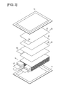
- FIG. 3 is an exploded oblique view of the battery cell.
- the battery cell 10 has a flattened rectangular shape, with a positive electrode lead 11 and a negative lead 12 exiting from the same end of an external packaging 13.
- the external packaging 13, for example, is produced by applying a resin coating to the surface of an aluminum sheet.
- the interior of the external packaging 13 contains electrolyte and an electricity-generating element (battery element) 15 whereby the charging and discharging reactions occur.
- the electricity-generating element 15 is formed by alternately layering positive electrodes 30 and negative electrodes 40, with sheet-form separators 20 interposed therebetween. In some cases, air, gas, or the like remains in the battery element 15 (separator 20) after the electricity-generating element 15 has been disposed in the external packaging 13, or after the electrolyte has been added.
- a positive active substance layer 32 is formed on both surfaces of a sheet-form positive electrode collector.
- the positive active substance layer 32 is not formed on the tab portions 34 of the positive electrodes 30.
- the respective tab portions 34 of the positive electrodes 30 are disposed at overlapping positions as seen from the layering direction in the electricity-generating element 15.
- the tab portions 34 connect with a positive electrode lead 11.
- a negative electrode active substance layer 42 is formed on both surfaces of a sheet-form negative electrode collector.
- the negative active substance layer 42 is not formed on the tab portions 44 of the negative electrodes 40.
- the respective tab portions 44 of the negative electrodes 40 are disposed at overlapping positions as seen from the direction of layering of the electricity-generating element 15 and are disposed so as not to overlap with the tab portions 34 of the positive electrodes 30.
- the tab portions 44 are connected to a negative electrode lead 12.
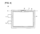
- FIG. 4 is a diagram showing the reinforcing part in the battery cell.
- the sealing part 16 indicated by the slanted lines in the drawing is shown for purposes of describing its position, but cannot actually be seen from outside the battery cell 10.
- the external packaging 13 of the battery cell 10 contains a battery element 15 between two sheets of rectangular laminated sheet (external packaging sheet).
- the packaging is formed so as to be sealed by a sealing part 16 that runs along each edge of the rectangular form.
- Adhesion of the external packaging 13 can be achieved, for example, by heat-fusing of the resin that coats the external packaging 13 or by adhesion using an adhesive.
- the sealing part 16 is formed at a location that is at a prescribed separation from each edge of the battery cell 10. Specifically, the sealing part is smaller all around than the external shape of the battery cell 10.
- the sealing part 16 is formed in the shape of an open box so as to approach one portion of the edge 17.
- one edge of the battery cell 10 is used as a gas extraction opening 18 for discharging air or gas in the external packaging 13.
- the edge 17 of the battery cell 10 is cut off at the location indicated by the dotted line A in the drawing, and when this is done, the gas extraction opening 18 passes through the inner and outer parts of the external packaging 13. Gas or the like in the external packaging 13 is discharged through the gas extraction opening 18. Subsequently, the external packaging 13 is adhered in the portion of the gas extraction opening 18, thereby resealing the battery cell 10.
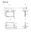
- FIG. 5 is a diagram showing the elements involved in transport and carrying of the battery cell.
- FIG. 5(A) shows a plan view of the elements of the battery cell 10.
- FIG. 5(B) shows the elements as viewed from the direction of arrow 5B in FIG. 5(A) .
- the battery cell 10 is transported by a transport device 50.
- the transport device 50 in this embodiment transports the battery cell 10 through the air with the battery cell suspended in a state in which the short edge of the rectangular form of the battery cell 10 is standing vertically.
- the transport device 50 for example, is a transport robot that transports the battery cell by sandwiching the upper part of the flat surface of the battery cell 10 from both sides with gripping parts 52.
- the transport device 50 transports the battery cells 10 to various processing or treatment steps, transfers the battery cells 10 to other devices, and removes the battery cells from other devices.
- Examples of other devices include receiving stands for temporarily carrying the battery cells 10, storage devices for storing the battery cells 10, and transport devices for transporting the battery cells 10 that employ methods other than those of the transport device 50.
- these may be processing devices or processing stands for carrying out prescribed processes on the battery cells 10. A case is described below in which the battery cell 10 is transferred to a receiving stand 60 shown in the bottom of the drawing.
- the receiving stand 60 has a support part 62 that supports the battery cell 10 from both surfaces.
- the battery cell 10 is transported over the receiving stand 60 by the transport device 50, and the battery cell 10 is inserted between the supports parts 62 of the receiving stand 60 when the transport device 50 approaches the receiving stand 60.
- the transport device 50 releases the gripping parts 52, the battery cell 10 is stored in the receiving stand 60.
- the transport device 50 approaches the receiving stand 60, and the battery cell 10 is gripped by the gripping parts 52. By raising the transport device 50, the battery cell 10 is removed from the receiving stand 60.
- the battery cell 10 is transported in a state of being positioned over the gas extraction opening 18 and is stored in the receiving stand 60 from the opposite edge from the gas extraction opening 18. Consequently, the edge of the battery cell 10 opposite the gas extraction opening 18 often contacts other devices such as the receiving stand 60.
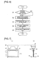
- FIG. 6 is a flow chart showing the sequence of the battery reinforcement method.
- FIG. 7 is a diagram showing the elements involved in checking battery cell deformation.
- FIG. 8 is a diagram showing the elements involved in forming the reinforcing part.
- FIG. 9 is a diagram showing the reinforcing part formed in the battery cell.
- FIG. 10 is a diagram showing the elements involved in rounding the reinforcing part.
- the battery cell 10 is transported by the transport device 50 to a prescribed position, and a check is performed to determine whether there is deformation such as bending at locations on the battery cell 10 to be reinforced (step S1).
- the sensor 70 shown in FIG. 7 detects deformation.
- the sensor 70 for example, is a pair of photoelectric sensors which can check for deformation of the external packaging 13 of the battery cell 10 by using one to detect the amount of light that has been emitted from the other.
- the external packaging 13, as shown in FIG. 5 often contacts other devices at the edge that is positioned downward in the drawing, and, in particular, is often deformed at the corners. Consequently, for example, it is desirable to detect bending at the corner portions of the external packaging 13 represented by the dotted lines in FIG. 7 .
- step S2 When bending of the external packaging 13 is detected by the sensor 70 (step S1: YES), deformation is corrected (step S2). Bend correction, for example, involves a pressing roller that evens out the external packaging 13 by pressing so as to be perfectly straight. However, deformation of the external packaging 13 may be corrected by any method.
- step S3 the battery cell 10 is then subjected to reinforcing part formation.
- the lower part of the external packaging 13 of the battery cell 10 is thermally fused by a heat-fusing device 72.
- the heat-fusing device 72 has a pair of blocks that abut the part of the external packaging 13 where the reinforcing part is to be formed, pressing it while heating from both sides, thereby fusing the resin of the external packaging 13. As shown in FIG.
- the reinforcing part 80 is formed outwards from the sealing part 16 of the battery cell 10 on an edge 19 that is different from the edge 17 on which the gas extraction opening 18 has been formed.
- the sealing part 16 that seals the external packaging 13 can be formed by heat-fusing
- the reinforcing part 80 can be formed by heat-fusing with a different degree of precision than used for the sealing part 16.
- the sealing part 16 can be formed by high-precision heat-fusing
- the reinforcing part 80 can be formed by comparatively low-precision heat-fusing.
- step S4 the corners of the reinforcing part 80 that has been formed in the battery cell 10 are rounded (step S4).
- the reinforcing part 80 as shown in FIG. 10 , is rounded using scissors 74.
- the scissors 74 approach the corners of the battery cell 10 that is carried on the receiving stand 60 or the like, and the corners are cut off. The portions drawn in black in FIGS. 9 and 10 are cut away.
- step S4 the battery cell 10 is transported to various devices for processing or the like. At this time, the battery cell 10 is placed in and removed from the receiving stand 60 or storage. After completion of the primary and other processes for the battery cell 10, but prior to shipping the battery cell 10 product, the reinforcing part 80 is cut away from the battery cell 10 (step S5). The reinforcing part 80 is cut away at the location indicated by the dotted line B in FIG. 9 .
- a reinforcing part 80 is formed on the edge 19 that is different from the edge 17 on which has been formed the gas extraction opening 18 that is used for gas discharge.
- the edge 19 that is not the edge 17, as described above, often comes into contact with other devices such as transport devices 50 or receiving stands 60 when transporting the battery cell 10 or when supporting the battery cells for processing. Consequently, by reinforcing the edge 19, deformation of the external packaging 13 of the battery cell 10 due to contact with other devices can be prevented.
- the reinforcing part 80 can be formed without the addition of other members, and so the prevention of deformation can be realized at low cost without excess costs required for the reinforcing part 80.
- the reinforcing part 80 is formed outwards and separately from the laminated sheet sealing part 16 of the external packaging 13. Consequently, the reinforcing part 80 can be formed with different standards or at a different precision from the sealing part 16. Because the reinforcing part 80 is formed separate from the sealing part 16, the sealing part 16 can be protected by the reinforcing part 80 during transport of the battery cell 10 or in other circumstances.
- sealing part 16 and the reinforcing part 80 can be achieved separately from the other by heat-fusing of the resin on the laminated sheet. Consequently, the sealing part 16 and the reinforcing part 80 can be formed separately using laminated sheets having the same configuration.
- deformation of the external packaging 13 is checked with the sensor 70, and thus deformation of the edge can be reliably detected.
- the reinforcing part 80 is formed on the edge 19 of the battery cell 10 that is in contact with other devices such as the receiving stand 60, and thus deformation of the external packaging 13 of the battery cell 10 due to contact with other devices can be prevented.
- edge 19 that has been reinforced by the reinforcing part 80 has rounded corners, distribution of load to the corners and deformation of the edge 19 can be prevented when the battery cell 10 is inserted from the reinforced edge 19 into other devices such as a receiving stand 60.
- the reinforcing part 80 is provided in a step such as processing of the battery cell 10, and deformation of the external packaging 13 of the battery cell 10 is prevented, with the reinforcing part 80 being then cut away in the end. Consequently, the reinforcing part 80 that has incurred some scratching in processing or other steps while reinforcing the battery cell will not remain on the battery cell 10 in the final product. A battery cell 10 is thus obtained that has absolutely no scratching.
- FIG. 11 is a diagram showing a battery cell in which another reinforcing part has been formed.
- the reinforcing part 80 was formed along an edge 19 of the battery cell 10, but the invention is not limited thereby.
- reinforcing parts 81, 82 may be formed on the edges that stand vertically.
- the method for forming the reinforcing parts 81, 82 may be the same as described above, i.e., formation by thermocompression-bonding of the resin in the laminated sheets.
- the reinforcing part 81 Prior to shipping the battery cell 10, the reinforcing part 81 may be cut off at the location indicated by the dotted line C.
- a reinforcing part 82 was formed also on the edge where the positive lead 11 and the negative lead 12 exit, but the reinforcing part 82 may remain as it cannot be cut off.
- the positive electrode lead 11 and the like are present on the same side as the reinforcing part 82, and excessive damage will not occur, so there will not be any problems with leaving the reinforcing part 82.
Landscapes
- Chemical & Material Sciences (AREA)
- Chemical Kinetics & Catalysis (AREA)
- Electrochemistry (AREA)
- General Chemical & Material Sciences (AREA)
- Inorganic Chemistry (AREA)
- Sealing Battery Cases Or Jackets (AREA)
Abstract
Description
- The present invention relates to a battery reinforcement method.
- Technologies are known in which multiple workpieces are stored in a rack, and the pitch of the multiple workpieces that are arranged in the rack is adjusted in accordance with the workpiece treatment step (for example, refer to patent document 1). With the invention according to
patent document 1, the workpieces are substrates, and the workpieces are held in grooves that are formed in a substrate holding member in a state in which the ends of the substrates fit therein. - On the other hand, with steps that involve processing battery cells, multiple battery cells are stored in the rack and are taken out and transported after adjusting the pitch as necessary.
- Patent Document 1: Japanese Laid-Open Patent Application No.
7-183357 - However, with battery cells, for example, the external packaging is formed from a laminate that is produced by coating aluminum sheet with resin, and so the ends of the external packages are not as hard as the substrates. Consequently, when the method according to
patent document 1 is used, and a battery cell is fit into a groove in the holding member, there is the risk that the external packaging will be damaged. - Even if the workpiece is not held in a state of fitting into the groove of the holding member as in
patent document 1, there is the risk that the external packaging of the battery cell will be damaged when the battery cell is stored in and removed from the predetermined rack or the like. - The present invention was developed in light of such circumstances, and it is an object of the invention to provide a battery reinforcement method for reinforcing the ends of battery cells so as to prevent damage.
- The battery reinforcement method is a method for reinforcing a rectangular battery cell in which a battery element is disposed in a rectangular external packaging. The external packaging is formed by enclosing the battery element between two rectangular external packaging sheets and sealing the resulting assembly with a sealing part that runs along each of the edges of the rectangular form. The battery reinforcement method includes a step in which a reinforcing part is formed to the outside of the sealing part in the external packaging. Effect of the Invention
- With the battery reinforcement method, a reinforcing part is formed to the outside, separate from a sealing part. Consequently, the sealing part can be protected by the reinforcing part during battery cell transport or the like.
-
- [
FIG. 1 ] Oblique view showing the exterior of the battery cell. - [
FIG. 2 ] Diagram showing a plan view and side view of the battery cell. - [
FIG. 3 ] Exploded perspective view of the battery cell. - [
FIG. 4 ] Diagram showing the sealing part inside the battery cell. - [
FIG. 5 ] Diagram showing the elements involved in transporting and carrying the battery cell. - [
FIG. 6 ] Flow chart showing the sequence of the battery reinforcement method. - [
FIG. 7 ] Diagram showing the elements involving in checking for deformation of the battery cell. - [
FIG. 8 ] Diagram showing the elements involved in forming the reinforcing part. - [
FIG. 9 ] Diagram showing the reinforcing part that is formed in the battery cell. - [
FIG. 10 ] Diagram showing the elements involved in rounding the reinforcing part. - [
FIG. 11 ] Diagram showing an additional battery cell in which a reinforcing part has been formed. - Embodiments of the present invention are described below with reference to the accompanying drawings. In the descriptions of the drawings, the same symbols refer to the same elements, and duplicate descriptions are thus not made. The dimensional ratios in the drawings may be exaggerated in order to aid in description and thus may differ from the true ratios in some instances.
- The present invention relates to a battery reinforcement method for reinforcing a battery cell. The configuration of the battery that is to be reinforced will be described prior to describing the battery reinforcement method.
-
FIG. 1 is an oblique view showing the exterior of a battery cell.FIG. 2 is a diagram showing a plan view and side view of the battery cell.FIG. 3 is an exploded oblique view of the battery cell. - As shown in
FIG. 1 andFIG. 2 , thebattery cell 10 has a flattened rectangular shape, with apositive electrode lead 11 and anegative lead 12 exiting from the same end of anexternal packaging 13. Theexternal packaging 13, for example, is produced by applying a resin coating to the surface of an aluminum sheet. - As shown in
FIG. 3 , the interior of theexternal packaging 13 contains electrolyte and an electricity-generating element (battery element) 15 whereby the charging and discharging reactions occur. The electricity-generatingelement 15 is formed by alternately layeringpositive electrodes 30 and negative electrodes 40, with sheet-form separators 20 interposed therebetween. In some cases, air, gas, or the like remains in the battery element 15 (separator 20) after the electricity-generatingelement 15 has been disposed in theexternal packaging 13, or after the electrolyte has been added. - With the
positive electrodes 30, a positiveactive substance layer 32 is formed on both surfaces of a sheet-form positive electrode collector. The positiveactive substance layer 32 is not formed on thetab portions 34 of thepositive electrodes 30. Therespective tab portions 34 of thepositive electrodes 30 are disposed at overlapping positions as seen from the layering direction in the electricity-generatingelement 15. Thetab portions 34 connect with apositive electrode lead 11. - With the negative electrodes 40, a negative electrode active substance layer 42 is formed on both surfaces of a sheet-form negative electrode collector. The negative active substance layer 42 is not formed on the
tab portions 44 of the negative electrodes 40. Therespective tab portions 44 of the negative electrodes 40 are disposed at overlapping positions as seen from the direction of layering of the electricity-generatingelement 15 and are disposed so as not to overlap with thetab portions 34 of thepositive electrodes 30. Thetab portions 44 are connected to anegative electrode lead 12. -
FIG. 4 is a diagram showing the reinforcing part in the battery cell. The sealingpart 16 indicated by the slanted lines in the drawing is shown for purposes of describing its position, but cannot actually be seen from outside thebattery cell 10. - The
external packaging 13 of thebattery cell 10 contains abattery element 15 between two sheets of rectangular laminated sheet (external packaging sheet). The packaging is formed so as to be sealed by a sealingpart 16 that runs along each edge of the rectangular form. For example, in the region indicated by the slanted lines inFIG. 4 , theexternal packaging 13 is adhered, forming a sealingpart 16. Adhesion of theexternal packaging 13 can be achieved, for example, by heat-fusing of the resin that coats theexternal packaging 13 or by adhesion using an adhesive. The sealingpart 16 is formed at a location that is at a prescribed separation from each edge of thebattery cell 10. Specifically, the sealing part is smaller all around than the external shape of thebattery cell 10. However, on oneedge 17 of thebattery cell 10, the sealingpart 16 is formed in the shape of an open box so as to approach one portion of theedge 17. With theedge 17, one edge of thebattery cell 10 is used as a gas extraction opening 18 for discharging air or gas in theexternal packaging 13. Theedge 17 of thebattery cell 10 is cut off at the location indicated by the dotted line A in the drawing, and when this is done, the gas extraction opening 18 passes through the inner and outer parts of theexternal packaging 13. Gas or the like in theexternal packaging 13 is discharged through thegas extraction opening 18. Subsequently, theexternal packaging 13 is adhered in the portion of thegas extraction opening 18, thereby resealing thebattery cell 10. - The elements involved in transporting and storing the
battery cells 10 will now be described. -
FIG. 5 is a diagram showing the elements involved in transport and carrying of the battery cell.FIG. 5(A) shows a plan view of the elements of thebattery cell 10.FIG. 5(B) shows the elements as viewed from the direction of arrow 5B inFIG. 5(A) . - As shown in
FIG. 5 , thebattery cell 10 is transported by atransport device 50. Thetransport device 50 in this embodiment transports thebattery cell 10 through the air with the battery cell suspended in a state in which the short edge of the rectangular form of thebattery cell 10 is standing vertically. Thetransport device 50, for example, is a transport robot that transports the battery cell by sandwiching the upper part of the flat surface of thebattery cell 10 from both sides withgripping parts 52. - The
transport device 50 transports thebattery cells 10 to various processing or treatment steps, transfers thebattery cells 10 to other devices, and removes the battery cells from other devices. Examples of other devices include receiving stands for temporarily carrying thebattery cells 10, storage devices for storing thebattery cells 10, and transport devices for transporting thebattery cells 10 that employ methods other than those of thetransport device 50. Alternatively, these may be processing devices or processing stands for carrying out prescribed processes on thebattery cells 10. A case is described below in which thebattery cell 10 is transferred to a receivingstand 60 shown in the bottom of the drawing. - The receiving
stand 60 has asupport part 62 that supports thebattery cell 10 from both surfaces. Thebattery cell 10 is transported over the receivingstand 60 by thetransport device 50, and thebattery cell 10 is inserted between thesupports parts 62 of the receivingstand 60 when thetransport device 50 approaches the receivingstand 60. When thetransport device 50 releases thegripping parts 52, thebattery cell 10 is stored in the receivingstand 60. When thebattery cell 10 is to be removed from the receivingstand 60, thetransport device 50 approaches the receivingstand 60, and thebattery cell 10 is gripped by thegripping parts 52. By raising thetransport device 50, thebattery cell 10 is removed from the receivingstand 60. - As described above, in this embodiment, the
battery cell 10 is transported in a state of being positioned over thegas extraction opening 18 and is stored in the receivingstand 60 from the opposite edge from thegas extraction opening 18. Consequently, the edge of thebattery cell 10 opposite thegas extraction opening 18 often contacts other devices such as the receivingstand 60. - The method for reinforcing the
battery cell 10 in the state prior to opening of thegas extraction opening 18, i.e., the state shown inFIG. 4 , is described in detail below. -
FIG. 6 is a flow chart showing the sequence of the battery reinforcement method.FIG. 7 is a diagram showing the elements involved in checking battery cell deformation.FIG. 8 is a diagram showing the elements involved in forming the reinforcing part.FIG. 9 is a diagram showing the reinforcing part formed in the battery cell.FIG. 10 is a diagram showing the elements involved in rounding the reinforcing part. - First, the
battery cell 10 is transported by thetransport device 50 to a prescribed position, and a check is performed to determine whether there is deformation such as bending at locations on thebattery cell 10 to be reinforced (step S1). Thesensor 70 shown inFIG. 7 detects deformation. Thesensor 70, for example, is a pair of photoelectric sensors which can check for deformation of theexternal packaging 13 of thebattery cell 10 by using one to detect the amount of light that has been emitted from the other. Theexternal packaging 13, as shown inFIG. 5 , often contacts other devices at the edge that is positioned downward in the drawing, and, in particular, is often deformed at the corners. Consequently, for example, it is desirable to detect bending at the corner portions of theexternal packaging 13 represented by the dotted lines inFIG. 7 . - When bending of the
external packaging 13 is detected by the sensor 70 (step S1: YES), deformation is corrected (step S2). Bend correction, for example, involves a pressing roller that evens out theexternal packaging 13 by pressing so as to be perfectly straight. However, deformation of theexternal packaging 13 may be corrected by any method. - Next, if no bending is found (step S1: NO), or when bending has been corrected (step S2), the
battery cell 10 is then subjected to reinforcing part formation (step S3). When forming the reinforcing part, as shown inFIG. 8 , the lower part of theexternal packaging 13 of thebattery cell 10 is thermally fused by a heat-fusingdevice 72. The heat-fusingdevice 72 has a pair of blocks that abut the part of theexternal packaging 13 where the reinforcing part is to be formed, pressing it while heating from both sides, thereby fusing the resin of theexternal packaging 13. As shown inFIG. 9 , the reinforcingpart 80 is formed outwards from the sealingpart 16 of thebattery cell 10 on anedge 19 that is different from theedge 17 on which thegas extraction opening 18 has been formed. Although the sealingpart 16 that seals theexternal packaging 13 can be formed by heat-fusing, the reinforcingpart 80 can be formed by heat-fusing with a different degree of precision than used for the sealingpart 16. For example, the sealingpart 16 can be formed by high-precision heat-fusing, whereas the reinforcingpart 80 can be formed by comparatively low-precision heat-fusing. - Next, the corners of the reinforcing
part 80 that has been formed in thebattery cell 10 are rounded (step S4). The reinforcingpart 80, as shown inFIG. 10 , is rounded usingscissors 74. Thescissors 74 approach the corners of thebattery cell 10 that is carried on the receivingstand 60 or the like, and the corners are cut off. The portions drawn in black inFIGS. 9 and10 are cut away. - After step S4, the
battery cell 10 is transported to various devices for processing or the like. At this time, thebattery cell 10 is placed in and removed from the receivingstand 60 or storage. After completion of the primary and other processes for thebattery cell 10, but prior to shipping thebattery cell 10 product, the reinforcingpart 80 is cut away from the battery cell 10 (step S5). The reinforcingpart 80 is cut away at the location indicated by the dotted line B inFIG. 9 . - As described above, in this embodiment, a reinforcing
part 80 is formed on theedge 19 that is different from theedge 17 on which has been formed thegas extraction opening 18 that is used for gas discharge. Theedge 19 that is not theedge 17, as described above, often comes into contact with other devices such astransport devices 50 or receiving stands 60 when transporting thebattery cell 10 or when supporting the battery cells for processing. Consequently, by reinforcing theedge 19, deformation of theexternal packaging 13 of thebattery cell 10 due to contact with other devices can be prevented. In addition, the reinforcingpart 80 can be formed without the addition of other members, and so the prevention of deformation can be realized at low cost without excess costs required for the reinforcingpart 80. - In addition, the reinforcing
part 80 is formed outwards and separately from the laminatedsheet sealing part 16 of theexternal packaging 13. Consequently, the reinforcingpart 80 can be formed with different standards or at a different precision from the sealingpart 16. Because the reinforcingpart 80 is formed separate from the sealingpart 16, the sealingpart 16 can be protected by the reinforcingpart 80 during transport of thebattery cell 10 or in other circumstances. - Formation of the sealing
part 16 and the reinforcingpart 80 can be achieved separately from the other by heat-fusing of the resin on the laminated sheet. Consequently, the sealingpart 16 and the reinforcingpart 80 can be formed separately using laminated sheets having the same configuration. - In addition, because deformation of the
external packaging 13 is corrected prior to formation of the reinforcingpart 80, unnecessary curling or creasing can be prevented at the edges by forming the reinforcingpart 80 with the edges of theexternal packaging 13 having been deformed. - Prior to forming the reinforcing
part 80, deformation of theexternal packaging 13 is checked with thesensor 70, and thus deformation of the edge can be reliably detected. - The reinforcing
part 80 is formed on theedge 19 of thebattery cell 10 that is in contact with other devices such as the receivingstand 60, and thus deformation of theexternal packaging 13 of thebattery cell 10 due to contact with other devices can be prevented. - Because the
edge 19 that has been reinforced by the reinforcingpart 80 has rounded corners, distribution of load to the corners and deformation of theedge 19 can be prevented when thebattery cell 10 is inserted from the reinforcededge 19 into other devices such as a receivingstand 60. - The reinforcing
part 80 is provided in a step such as processing of thebattery cell 10, and deformation of theexternal packaging 13 of thebattery cell 10 is prevented, with the reinforcingpart 80 being then cut away in the end. Consequently, the reinforcingpart 80 that has incurred some scratching in processing or other steps while reinforcing the battery cell will not remain on thebattery cell 10 in the final product. Abattery cell 10 is thus obtained that has absolutely no scratching. - The present invention was described above in relation to embodiments, but the present invention is not limited to these embodiments, as various modifications are possible.
-
FIG. 11 is a diagram showing a battery cell in which another reinforcing part has been formed. - In the embodiments described above, the reinforcing
part 80 was formed along anedge 19 of thebattery cell 10, but the invention is not limited thereby. As shown inFIG. 11 , reinforcingparts parts battery cell 10, the reinforcingpart 81 may be cut off at the location indicated by the dotted line C. InFIG. 11 , a reinforcingpart 82 was formed also on the edge where thepositive lead 11 and thenegative lead 12 exit, but the reinforcingpart 82 may remain as it cannot be cut off. Thepositive electrode lead 11 and the like are present on the same side as the reinforcingpart 82, and excessive damage will not occur, so there will not be any problems with leaving the reinforcingpart 82. - In addition, in the embodiment described above, an example was described in which the
battery cell 10 was carried on the receivingstand 60, and thebattery cell 10 was removed from the receivingstand 60, but such an arrangement is not provided by way of limitation. Reinforcement of thebattery cell 10 is effective, even in cases where thebattery cell 10 is transferred to a storage rack that storesmultiple battery cells 10, whereupon the battery cells are then removed from the storage rack. - This application is based on Patent Application
2012-28515 -
- 10
- Battery cell
- 11
- Positive electrode lead
- 12
- Negative electrode lead
- 13
- External packaging
- 15
- Battery element
- 16
- Sealing part
- 17, 19
- Edge
- 18
- Gas extraction opening
- 20
- Separator
- 30
- Positive electrode
- 40
- Negative electrode
- 50
- Transport device
- 52
- Gripping part
- 60
- Receiving stand
- 62
- Support part
- 70
- Sensor
- 72
- Heat-fusing device
- 74
- Scissors
- 80, 81, 82
- Reinforcing part
Claims (8)
- A battery reinforcement method for reinforcing a rectangular battery cell in which a battery element is disposed in a rectangular external packaging, wherein the method comprises forming the external packaging by enclosing the battery element between two rectangular external packaging sheets and sealing the resulting assembly with a sealing part that runs along the edges of the rectangular form; and comprises a step of forming a reinforcing part to the outside of the sealing part in the external packaging.
- The battery reinforcement method according to claim 1, wherein the reinforcing part is formed on at least a part of an edge of the external packaging sheet that is different from an edge of the rectangular form that is used for discharging gas.
- The battery reinforcement method according to claim 1 or claim 2, wherein the external packaging sheets are formed by coating a metal sheet with a resin, and the sealing part and reinforcing part are formed independently from each other by thermocompression-bonding the resin that coats the two external packaging sheets.
- The battery reinforcement method according to any of claims 1 to 3, further comprising a step for correcting deformation of a portion of the edge on which the reinforcing part is to be formed, the deformation-correcting step being carried out prior to the step for forming the reinforcing part on at least a part of an edge of the battery cell.
- The battery reinforcement method according to any of claims 1 to 4, further comprising a step for detecting defonnation of the portion of the edge on which the reinforcing part is to be formed, the deformation-detecting step being carried out prior to the step for forming the reinforcing part on at least part of an edge of the battery cell.
- The battery reinforcement method according to any of claims 1 to 5, wherein the reinforcing part is formed on an edge of the battery cell that is to be in contact with another device when the battery cell is transferred to or receive from the another device.
- The battery reinforcement method according to any of claims 1 to 6, further comprising a step for rounding the corners of an edge that has been reinforced by the reinforcing part.
- The battery reinforcement method according to any of claims 1 to 7, further comprising a step for cutting a portion of the edge of the battery cell on which the reinforcing part has been formed.
Applications Claiming Priority (2)
| Application Number | Priority Date | Filing Date | Title |
|---|---|---|---|
| JP2012028515A JP5909378B2 (en) | 2012-02-13 | 2012-02-13 | Battery reinforcement method |
| PCT/JP2013/053381 WO2013122097A1 (en) | 2012-02-13 | 2013-02-13 | Battery reinforcement method |
Publications (3)
| Publication Number | Publication Date |
|---|---|
| EP2816631A1 true EP2816631A1 (en) | 2014-12-24 |
| EP2816631A4 EP2816631A4 (en) | 2015-07-29 |
| EP2816631B1 EP2816631B1 (en) | 2021-03-24 |
Family
ID=48984206
Family Applications (1)
| Application Number | Title | Priority Date | Filing Date |
|---|---|---|---|
| EP13748485.3A Active EP2816631B1 (en) | 2012-02-13 | 2013-02-13 | Battery reinforcement method |
Country Status (5)
| Country | Link |
|---|---|
| US (1) | US9553285B2 (en) |
| EP (1) | EP2816631B1 (en) |
| JP (1) | JP5909378B2 (en) |
| CN (1) | CN104115302B (en) |
| WO (1) | WO2013122097A1 (en) |
Cited By (1)
| Publication number | Priority date | Publication date | Assignee | Title |
|---|---|---|---|---|
| EP4120446A4 (en) * | 2020-11-09 | 2024-03-06 | LG Energy Solution, Ltd. | SECONDARY BATTERY |
Families Citing this family (1)
| Publication number | Priority date | Publication date | Assignee | Title |
|---|---|---|---|---|
| US9837682B1 (en) | 2016-08-29 | 2017-12-05 | Microsoft Technology Licensing, Llc | Variable layer thickness in curved battery cell |
Family Cites Families (12)
| Publication number | Priority date | Publication date | Assignee | Title |
|---|---|---|---|---|
| GB2087779B (en) * | 1980-11-20 | 1985-05-15 | Rhodes Joseph Ltd | Metal trimmer |
| JPH07183357A (en) | 1993-12-22 | 1995-07-21 | Dainippon Screen Mfg Co Ltd | Substrate arrangement pitch converter |
| JP3709134B2 (en) * | 2000-11-22 | 2005-10-19 | 松下電器産業株式会社 | Square battery |
| EP1747439B1 (en) * | 2004-05-12 | 2012-03-21 | PIRELLI TYRE S.p.A. | Method for determining a force at the hub of a wheel of a vehicle whilst traveling and wheel suitable for allowing said method to be carried out |
| JP4744816B2 (en) * | 2004-06-03 | 2011-08-10 | 株式会社東芝 | Thin non-aqueous electrolyte secondary battery |
| WO2006098242A1 (en) * | 2005-03-17 | 2006-09-21 | Nec Corporation | Film enclosed electric device and production method therefor |
| JP5108411B2 (en) * | 2007-08-03 | 2012-12-26 | パナソニック株式会社 | Battery can, manufacturing method and manufacturing apparatus |
| US20090169977A1 (en) * | 2007-12-31 | 2009-07-02 | Apple Inc. | Systems and methods for monitoring and responding to forces influencing a battery |
| DE102008047615A1 (en) * | 2008-09-17 | 2010-04-15 | Li-Tec Battery Gmbh | accumulator |
| JP2010198988A (en) * | 2009-02-26 | 2010-09-09 | Sumitomo Chemical Co Ltd | Film case type power storage device |
| US8771866B2 (en) | 2010-03-30 | 2014-07-08 | Samsung Sdi Co., Ltd. | Pouch type secondary battery and the fabrication method thereof |
| JP2012204002A (en) * | 2011-03-23 | 2012-10-22 | Nec Tokin Corp | Power storage device |
-
2012
- 2012-02-13 JP JP2012028515A patent/JP5909378B2/en active Active
-
2013
- 2013-02-13 US US14/376,649 patent/US9553285B2/en active Active
- 2013-02-13 CN CN201380008850.XA patent/CN104115302B/en active Active
- 2013-02-13 WO PCT/JP2013/053381 patent/WO2013122097A1/en not_active Ceased
- 2013-02-13 EP EP13748485.3A patent/EP2816631B1/en active Active
Cited By (1)
| Publication number | Priority date | Publication date | Assignee | Title |
|---|---|---|---|---|
| EP4120446A4 (en) * | 2020-11-09 | 2024-03-06 | LG Energy Solution, Ltd. | SECONDARY BATTERY |
Also Published As
| Publication number | Publication date |
|---|---|
| EP2816631B1 (en) | 2021-03-24 |
| CN104115302A (en) | 2014-10-22 |
| JP5909378B2 (en) | 2016-04-26 |
| US20150026969A1 (en) | 2015-01-29 |
| WO2013122097A1 (en) | 2013-08-22 |
| JP2013165038A (en) | 2013-08-22 |
| CN104115302B (en) | 2017-12-01 |
| US9553285B2 (en) | 2017-01-24 |
| EP2816631A4 (en) | 2015-07-29 |
Similar Documents
| Publication | Publication Date | Title |
|---|---|---|
| EP2985805B1 (en) | Curved secondary battery and method of manufacturing the same | |
| EP3588653B1 (en) | Method for producing mono-cell | |
| EP2884560B1 (en) | Flexible secondary battery | |
| EP3955355A1 (en) | Multi-plate laminating device for lithium battery cell and laminating method thereof | |
| CN107646153B (en) | Sheet attachment device for battery pack | |
| EP4120410A1 (en) | Unit cell manufacturing device and method | |
| US10297868B2 (en) | Method for manufacturing electrode assembly for secondary battery | |
| US20060127732A1 (en) | Fuel cell stacking method and fuel cell tracking device | |
| JP2011181395A (en) | Laminated lithium ion secondary battery, and method and device of manufacturing the same | |
| EP4109610A1 (en) | Apparatus and method for manufacturing unit cell | |
| JP6642072B2 (en) | Secondary battery manufacturing apparatus and secondary battery manufacturing method | |
| US9685648B2 (en) | Bus bar attachment device and bus bar attachment method | |
| KR20210110556A (en) | Battery Case Having Buffering Recess Portion formed at Connection Portion Between Two Receiving parts | |
| KR20150056932A (en) | Apparatus for Attaching the Adhesion Member for Fixing Battery Assembly | |
| EP2816631A1 (en) | Battery reinforcement method | |
| JPWO2020110207A1 (en) | Positioning transfer device and positioning transfer method | |
| JP2012185976A (en) | Laminated battery | |
| KR20130112773A (en) | Tab lead packing container and tab lead package | |
| CN220290878U (en) | Device for manufacturing unit cell | |
| EP4254577B1 (en) | Secondary battery manufacturing system and manufacturing method | |
| KR102263450B1 (en) | Battery Cell Comprising Protection Pad Applied on Outer Surface of Battery Case | |
| KR20250135404A (en) | Pressurization device for a secondary battery, a secondary battery manufactured using the device, and a method for manufacturing the same | |
| KR200286113Y1 (en) | Roll folding apparatus of polymer battery | |
| KR20260054213A (en) | Cell aligning apparatus and cell stacking apparatus including the same |
Legal Events
| Date | Code | Title | Description |
|---|---|---|---|
| PUAI | Public reference made under article 153(3) epc to a published international application that has entered the european phase |
Free format text: ORIGINAL CODE: 0009012 |
|
| 17P | Request for examination filed |
Effective date: 20140801 |
|
| AK | Designated contracting states |
Kind code of ref document: A1 Designated state(s): AL AT BE BG CH CY CZ DE DK EE ES FI FR GB GR HR HU IE IS IT LI LT LU LV MC MK MT NL NO PL PT RO RS SE SI SK SM TR |
|
| AX | Request for extension of the european patent |
Extension state: BA ME |
|
| DAX | Request for extension of the european patent (deleted) | ||
| RA4 | Supplementary search report drawn up and despatched (corrected) |
Effective date: 20150625 |
|
| RIC1 | Information provided on ipc code assigned before grant |
Ipc: H01M 2/06 20060101ALI20150619BHEP Ipc: H01M 2/02 20060101AFI20150619BHEP |
|
| STAA | Information on the status of an ep patent application or granted ep patent |
Free format text: STATUS: EXAMINATION IS IN PROGRESS |
|
| 17Q | First examination report despatched |
Effective date: 20171220 |
|
| RAP1 | Party data changed (applicant data changed or rights of an application transferred) |
Owner name: ENVISION AESC JAPAN LTD. |
|
| GRAP | Despatch of communication of intention to grant a patent |
Free format text: ORIGINAL CODE: EPIDOSNIGR1 |
|
| STAA | Information on the status of an ep patent application or granted ep patent |
Free format text: STATUS: GRANT OF PATENT IS INTENDED |
|
| INTG | Intention to grant announced |
Effective date: 20201021 |
|
| GRAS | Grant fee paid |
Free format text: ORIGINAL CODE: EPIDOSNIGR3 |
|
| GRAA | (expected) grant |
Free format text: ORIGINAL CODE: 0009210 |
|
| STAA | Information on the status of an ep patent application or granted ep patent |
Free format text: STATUS: THE PATENT HAS BEEN GRANTED |
|
| AK | Designated contracting states |
Kind code of ref document: B1 Designated state(s): AL AT BE BG CH CY CZ DE DK EE ES FI FR GB GR HR HU IE IS IT LI LT LU LV MC MK MT NL NO PL PT RO RS SE SI SK SM TR |
|
| REG | Reference to a national code |
Ref country code: GB Ref legal event code: FG4D |
|
| REG | Reference to a national code |
Ref country code: CH Ref legal event code: EP |
|
| REG | Reference to a national code |
Ref country code: DE Ref legal event code: R096 Ref document number: 602013076437 Country of ref document: DE |
|
| REG | Reference to a national code |
Ref country code: IE Ref legal event code: FG4D |
|
| REG | Reference to a national code |
Ref country code: AT Ref legal event code: REF Ref document number: 1375408 Country of ref document: AT Kind code of ref document: T Effective date: 20210415 |
|
| REG | Reference to a national code |
Ref country code: LT Ref legal event code: MG9D |
|
| PG25 | Lapsed in a contracting state [announced via postgrant information from national office to epo] |
Ref country code: GR Free format text: LAPSE BECAUSE OF FAILURE TO SUBMIT A TRANSLATION OF THE DESCRIPTION OR TO PAY THE FEE WITHIN THE PRESCRIBED TIME-LIMIT Effective date: 20210625 Ref country code: FI Free format text: LAPSE BECAUSE OF FAILURE TO SUBMIT A TRANSLATION OF THE DESCRIPTION OR TO PAY THE FEE WITHIN THE PRESCRIBED TIME-LIMIT Effective date: 20210324 Ref country code: HR Free format text: LAPSE BECAUSE OF FAILURE TO SUBMIT A TRANSLATION OF THE DESCRIPTION OR TO PAY THE FEE WITHIN THE PRESCRIBED TIME-LIMIT Effective date: 20210324 Ref country code: BG Free format text: LAPSE BECAUSE OF FAILURE TO SUBMIT A TRANSLATION OF THE DESCRIPTION OR TO PAY THE FEE WITHIN THE PRESCRIBED TIME-LIMIT Effective date: 20210624 Ref country code: NO Free format text: LAPSE BECAUSE OF FAILURE TO SUBMIT A TRANSLATION OF THE DESCRIPTION OR TO PAY THE FEE WITHIN THE PRESCRIBED TIME-LIMIT Effective date: 20210624 |
|
| PG25 | Lapsed in a contracting state [announced via postgrant information from national office to epo] |
Ref country code: LV Free format text: LAPSE BECAUSE OF FAILURE TO SUBMIT A TRANSLATION OF THE DESCRIPTION OR TO PAY THE FEE WITHIN THE PRESCRIBED TIME-LIMIT Effective date: 20210324 Ref country code: RS Free format text: LAPSE BECAUSE OF FAILURE TO SUBMIT A TRANSLATION OF THE DESCRIPTION OR TO PAY THE FEE WITHIN THE PRESCRIBED TIME-LIMIT Effective date: 20210324 Ref country code: SE Free format text: LAPSE BECAUSE OF FAILURE TO SUBMIT A TRANSLATION OF THE DESCRIPTION OR TO PAY THE FEE WITHIN THE PRESCRIBED TIME-LIMIT Effective date: 20210324 |
|
| REG | Reference to a national code |
Ref country code: NL Ref legal event code: MP Effective date: 20210324 |
|
| REG | Reference to a national code |
Ref country code: AT Ref legal event code: MK05 Ref document number: 1375408 Country of ref document: AT Kind code of ref document: T Effective date: 20210324 |
|
| PG25 | Lapsed in a contracting state [announced via postgrant information from national office to epo] |
Ref country code: NL Free format text: LAPSE BECAUSE OF FAILURE TO SUBMIT A TRANSLATION OF THE DESCRIPTION OR TO PAY THE FEE WITHIN THE PRESCRIBED TIME-LIMIT Effective date: 20210324 |
|
| PG25 | Lapsed in a contracting state [announced via postgrant information from national office to epo] |
Ref country code: SM Free format text: LAPSE BECAUSE OF FAILURE TO SUBMIT A TRANSLATION OF THE DESCRIPTION OR TO PAY THE FEE WITHIN THE PRESCRIBED TIME-LIMIT Effective date: 20210324 Ref country code: AT Free format text: LAPSE BECAUSE OF FAILURE TO SUBMIT A TRANSLATION OF THE DESCRIPTION OR TO PAY THE FEE WITHIN THE PRESCRIBED TIME-LIMIT Effective date: 20210324 Ref country code: LT Free format text: LAPSE BECAUSE OF FAILURE TO SUBMIT A TRANSLATION OF THE DESCRIPTION OR TO PAY THE FEE WITHIN THE PRESCRIBED TIME-LIMIT Effective date: 20210324 Ref country code: CZ Free format text: LAPSE BECAUSE OF FAILURE TO SUBMIT A TRANSLATION OF THE DESCRIPTION OR TO PAY THE FEE WITHIN THE PRESCRIBED TIME-LIMIT Effective date: 20210324 Ref country code: EE Free format text: LAPSE BECAUSE OF FAILURE TO SUBMIT A TRANSLATION OF THE DESCRIPTION OR TO PAY THE FEE WITHIN THE PRESCRIBED TIME-LIMIT Effective date: 20210324 |
|
| PG25 | Lapsed in a contracting state [announced via postgrant information from national office to epo] |
Ref country code: ES Free format text: LAPSE BECAUSE OF FAILURE TO SUBMIT A TRANSLATION OF THE DESCRIPTION OR TO PAY THE FEE WITHIN THE PRESCRIBED TIME-LIMIT Effective date: 20210324 Ref country code: PL Free format text: LAPSE BECAUSE OF FAILURE TO SUBMIT A TRANSLATION OF THE DESCRIPTION OR TO PAY THE FEE WITHIN THE PRESCRIBED TIME-LIMIT Effective date: 20210324 Ref country code: PT Free format text: LAPSE BECAUSE OF FAILURE TO SUBMIT A TRANSLATION OF THE DESCRIPTION OR TO PAY THE FEE WITHIN THE PRESCRIBED TIME-LIMIT Effective date: 20210726 Ref country code: SK Free format text: LAPSE BECAUSE OF FAILURE TO SUBMIT A TRANSLATION OF THE DESCRIPTION OR TO PAY THE FEE WITHIN THE PRESCRIBED TIME-LIMIT Effective date: 20210324 Ref country code: RO Free format text: LAPSE BECAUSE OF FAILURE TO SUBMIT A TRANSLATION OF THE DESCRIPTION OR TO PAY THE FEE WITHIN THE PRESCRIBED TIME-LIMIT Effective date: 20210324 Ref country code: IS Free format text: LAPSE BECAUSE OF FAILURE TO SUBMIT A TRANSLATION OF THE DESCRIPTION OR TO PAY THE FEE WITHIN THE PRESCRIBED TIME-LIMIT Effective date: 20210724 |
|
| REG | Reference to a national code |
Ref country code: DE Ref legal event code: R097 Ref document number: 602013076437 Country of ref document: DE |
|
| PG25 | Lapsed in a contracting state [announced via postgrant information from national office to epo] |
Ref country code: AL Free format text: LAPSE BECAUSE OF FAILURE TO SUBMIT A TRANSLATION OF THE DESCRIPTION OR TO PAY THE FEE WITHIN THE PRESCRIBED TIME-LIMIT Effective date: 20210324 Ref country code: DK Free format text: LAPSE BECAUSE OF FAILURE TO SUBMIT A TRANSLATION OF THE DESCRIPTION OR TO PAY THE FEE WITHIN THE PRESCRIBED TIME-LIMIT Effective date: 20210324 |
|
| PLBE | No opposition filed within time limit |
Free format text: ORIGINAL CODE: 0009261 |
|
| STAA | Information on the status of an ep patent application or granted ep patent |
Free format text: STATUS: NO OPPOSITION FILED WITHIN TIME LIMIT |
|
| PG25 | Lapsed in a contracting state [announced via postgrant information from national office to epo] |
Ref country code: SI Free format text: LAPSE BECAUSE OF FAILURE TO SUBMIT A TRANSLATION OF THE DESCRIPTION OR TO PAY THE FEE WITHIN THE PRESCRIBED TIME-LIMIT Effective date: 20210324 |
|
| 26N | No opposition filed |
Effective date: 20220104 |
|
| PG25 | Lapsed in a contracting state [announced via postgrant information from national office to epo] |
Ref country code: IS Free format text: LAPSE BECAUSE OF FAILURE TO SUBMIT A TRANSLATION OF THE DESCRIPTION OR TO PAY THE FEE WITHIN THE PRESCRIBED TIME-LIMIT Effective date: 20210724 |
|
| PG25 | Lapsed in a contracting state [announced via postgrant information from national office to epo] |
Ref country code: MC Free format text: LAPSE BECAUSE OF FAILURE TO SUBMIT A TRANSLATION OF THE DESCRIPTION OR TO PAY THE FEE WITHIN THE PRESCRIBED TIME-LIMIT Effective date: 20210324 |
|
| REG | Reference to a national code |
Ref country code: CH Ref legal event code: PL |
|
| REG | Reference to a national code |
Ref country code: BE Ref legal event code: MM Effective date: 20220228 |
|
| PG25 | Lapsed in a contracting state [announced via postgrant information from national office to epo] |
Ref country code: LU Free format text: LAPSE BECAUSE OF NON-PAYMENT OF DUE FEES Effective date: 20220213 |
|
| PG25 | Lapsed in a contracting state [announced via postgrant information from national office to epo] |
Ref country code: LI Free format text: LAPSE BECAUSE OF NON-PAYMENT OF DUE FEES Effective date: 20220228 Ref country code: IT Free format text: LAPSE BECAUSE OF FAILURE TO SUBMIT A TRANSLATION OF THE DESCRIPTION OR TO PAY THE FEE WITHIN THE PRESCRIBED TIME-LIMIT Effective date: 20210324 Ref country code: IE Free format text: LAPSE BECAUSE OF NON-PAYMENT OF DUE FEES Effective date: 20220213 Ref country code: CH Free format text: LAPSE BECAUSE OF NON-PAYMENT OF DUE FEES Effective date: 20220228 |
|
| PG25 | Lapsed in a contracting state [announced via postgrant information from national office to epo] |
Ref country code: BE Free format text: LAPSE BECAUSE OF NON-PAYMENT OF DUE FEES Effective date: 20220228 |
|
| P01 | Opt-out of the competence of the unified patent court (upc) registered |
Effective date: 20230330 |
|
| PG25 | Lapsed in a contracting state [announced via postgrant information from national office to epo] |
Ref country code: HU Free format text: LAPSE BECAUSE OF FAILURE TO SUBMIT A TRANSLATION OF THE DESCRIPTION OR TO PAY THE FEE WITHIN THE PRESCRIBED TIME-LIMIT; INVALID AB INITIO Effective date: 20130213 |
|
| PG25 | Lapsed in a contracting state [announced via postgrant information from national office to epo] |
Ref country code: MK Free format text: LAPSE BECAUSE OF FAILURE TO SUBMIT A TRANSLATION OF THE DESCRIPTION OR TO PAY THE FEE WITHIN THE PRESCRIBED TIME-LIMIT Effective date: 20210324 Ref country code: CY Free format text: LAPSE BECAUSE OF FAILURE TO SUBMIT A TRANSLATION OF THE DESCRIPTION OR TO PAY THE FEE WITHIN THE PRESCRIBED TIME-LIMIT Effective date: 20210324 |
|
| PG25 | Lapsed in a contracting state [announced via postgrant information from national office to epo] |
Ref country code: MT Free format text: LAPSE BECAUSE OF FAILURE TO SUBMIT A TRANSLATION OF THE DESCRIPTION OR TO PAY THE FEE WITHIN THE PRESCRIBED TIME-LIMIT Effective date: 20210324 |
|
| PG25 | Lapsed in a contracting state [announced via postgrant information from national office to epo] |
Ref country code: TR Free format text: LAPSE BECAUSE OF FAILURE TO SUBMIT A TRANSLATION OF THE DESCRIPTION OR TO PAY THE FEE WITHIN THE PRESCRIBED TIME-LIMIT Effective date: 20210324 |
|
| PGFP | Annual fee paid to national office [announced via postgrant information from national office to epo] |
Ref country code: GB Payment date: 20260128 Year of fee payment: 14 |
|
| PGFP | Annual fee paid to national office [announced via postgrant information from national office to epo] |
Ref country code: DE Payment date: 20260121 Year of fee payment: 14 |
|
| PGFP | Annual fee paid to national office [announced via postgrant information from national office to epo] |
Ref country code: FR Payment date: 20260121 Year of fee payment: 14 |