EP2816369B1 - Detection system with multiple simultaneous emissions and detection method - Google Patents
Detection system with multiple simultaneous emissions and detection method Download PDFInfo
- Publication number
- EP2816369B1 EP2816369B1 EP14171667.0A EP14171667A EP2816369B1 EP 2816369 B1 EP2816369 B1 EP 2816369B1 EP 14171667 A EP14171667 A EP 14171667A EP 2816369 B1 EP2816369 B1 EP 2816369B1
- Authority
- EP
- European Patent Office
- Prior art keywords
- transmission
- sub
- codes
- array
- aggregation
- Prior art date
- Legal status (The legal status is an assumption and is not a legal conclusion. Google has not performed a legal analysis and makes no representation as to the accuracy of the status listed.)
- Active
Links
- 238000001514 detection method Methods 0.000 title claims description 48
- 230000005540 biological transmission Effects 0.000 claims description 61
- 238000002592 echocardiography Methods 0.000 claims description 14
- 238000007476 Maximum Likelihood Methods 0.000 claims description 7
- 238000000034 method Methods 0.000 claims description 3
- 238000004220 aggregation Methods 0.000 claims 12
- 230000002776 aggregation Effects 0.000 claims 12
- 238000003491 array Methods 0.000 claims 6
- 238000011282 treatment Methods 0.000 description 19
- 230000015572 biosynthetic process Effects 0.000 description 8
- 230000006835 compression Effects 0.000 description 8
- 238000007906 compression Methods 0.000 description 8
- 238000004364 calculation method Methods 0.000 description 6
- 238000001914 filtration Methods 0.000 description 5
- 241000861223 Issus Species 0.000 description 4
- 238000002310 reflectometry Methods 0.000 description 4
- 240000008042 Zea mays Species 0.000 description 3
- 230000003044 adaptive effect Effects 0.000 description 2
- 230000003247 decreasing effect Effects 0.000 description 2
- 238000010586 diagram Methods 0.000 description 2
- 230000000694 effects Effects 0.000 description 2
- 238000000605 extraction Methods 0.000 description 2
- 238000005259 measurement Methods 0.000 description 2
- 230000001869 rapid Effects 0.000 description 2
- 241001644893 Entandrophragma utile Species 0.000 description 1
- 241000680160 Opisthoproctidae Species 0.000 description 1
- 230000033228 biological regulation Effects 0.000 description 1
- 230000001427 coherent effect Effects 0.000 description 1
- 230000001934 delay Effects 0.000 description 1
- 230000008030 elimination Effects 0.000 description 1
- 238000003379 elimination reaction Methods 0.000 description 1
- 229940082150 encore Drugs 0.000 description 1
- 230000007274 generation of a signal involved in cell-cell signaling Effects 0.000 description 1
- 238000009413 insulation Methods 0.000 description 1
- 239000011159 matrix material Substances 0.000 description 1
- 230000035945 sensitivity Effects 0.000 description 1
- 230000001629 suppression Effects 0.000 description 1
Images


Classifications
-
- G—PHYSICS
- G01—MEASURING; TESTING
- G01S—RADIO DIRECTION-FINDING; RADIO NAVIGATION; DETERMINING DISTANCE OR VELOCITY BY USE OF RADIO WAVES; LOCATING OR PRESENCE-DETECTING BY USE OF THE REFLECTION OR RERADIATION OF RADIO WAVES; ANALOGOUS ARRANGEMENTS USING OTHER WAVES
- G01S7/00—Details of systems according to groups G01S13/00, G01S15/00, G01S17/00
- G01S7/02—Details of systems according to groups G01S13/00, G01S15/00, G01S17/00 of systems according to group G01S13/00
- G01S7/41—Details of systems according to groups G01S13/00, G01S15/00, G01S17/00 of systems according to group G01S13/00 using analysis of echo signal for target characterisation; Target signature; Target cross-section
- G01S7/414—Discriminating targets with respect to background clutter
-
- G—PHYSICS
- G01—MEASURING; TESTING
- G01S—RADIO DIRECTION-FINDING; RADIO NAVIGATION; DETERMINING DISTANCE OR VELOCITY BY USE OF RADIO WAVES; LOCATING OR PRESENCE-DETECTING BY USE OF THE REFLECTION OR RERADIATION OF RADIO WAVES; ANALOGOUS ARRANGEMENTS USING OTHER WAVES
- G01S13/00—Systems using the reflection or reradiation of radio waves, e.g. radar systems; Analogous systems using reflection or reradiation of waves whose nature or wavelength is irrelevant or unspecified
- G01S13/02—Systems using reflection of radio waves, e.g. primary radar systems; Analogous systems
- G01S13/06—Systems determining position data of a target
- G01S13/42—Simultaneous measurement of distance and other co-ordinates
-
- G—PHYSICS
- G01—MEASURING; TESTING
- G01S—RADIO DIRECTION-FINDING; RADIO NAVIGATION; DETERMINING DISTANCE OR VELOCITY BY USE OF RADIO WAVES; LOCATING OR PRESENCE-DETECTING BY USE OF THE REFLECTION OR RERADIATION OF RADIO WAVES; ANALOGOUS ARRANGEMENTS USING OTHER WAVES
- G01S13/00—Systems using the reflection or reradiation of radio waves, e.g. radar systems; Analogous systems using reflection or reradiation of waves whose nature or wavelength is irrelevant or unspecified
- G01S13/02—Systems using reflection of radio waves, e.g. primary radar systems; Analogous systems
- G01S13/06—Systems determining position data of a target
- G01S13/46—Indirect determination of position data
- G01S13/48—Indirect determination of position data using multiple beams at emission or reception
-
- G—PHYSICS
- G01—MEASURING; TESTING
- G01S—RADIO DIRECTION-FINDING; RADIO NAVIGATION; DETERMINING DISTANCE OR VELOCITY BY USE OF RADIO WAVES; LOCATING OR PRESENCE-DETECTING BY USE OF THE REFLECTION OR RERADIATION OF RADIO WAVES; ANALOGOUS ARRANGEMENTS USING OTHER WAVES
- G01S13/00—Systems using the reflection or reradiation of radio waves, e.g. radar systems; Analogous systems using reflection or reradiation of waves whose nature or wavelength is irrelevant or unspecified
- G01S13/02—Systems using reflection of radio waves, e.g. primary radar systems; Analogous systems
- G01S13/50—Systems of measurement based on relative movement of target
- G01S13/58—Velocity or trajectory determination systems; Sense-of-movement determination systems
- G01S13/583—Velocity or trajectory determination systems; Sense-of-movement determination systems using transmission of continuous unmodulated waves, amplitude-, frequency-, or phase-modulated waves and based upon the Doppler effect resulting from movement of targets
- G01S13/584—Velocity or trajectory determination systems; Sense-of-movement determination systems using transmission of continuous unmodulated waves, amplitude-, frequency-, or phase-modulated waves and based upon the Doppler effect resulting from movement of targets adapted for simultaneous range and velocity measurements
Definitions
- the present invention relates to a multiple simultaneous emission detection system. It also relates to a detection method using simultaneous multiple transmissions.
- the invention applies in particular in the field of multiple simultaneous emission radars also called MIMO ("Multiple Input Multiple Output”) radars or MISO (“Multiple Input Single Output”) radars. It can be terrestrial, naval, airborne or space-based radars. The invention can also be applied to active sonars.
- MIMO Multiple Input Multiple Output
- MISO Multiple Input Single Output
- a function is to detect slow objects and low reflectivity, such as drones in particular.
- To detect slow objects in the presence of clutter it is necessary to have a good Doppler resolution so a consistent long observation time.
- one solution is to use an expanded transmit beam and a receive beam cluster that covers the entire transmit beam.
- the beam is widened by a phase law.
- this solution does not provide the necessary insulation between the desired target of low reflectivity and low speed, such as a drone, and ground vehicles, the same speed and much stronger reflectivity.
- Another solution is to widen the beam by simultaneous multiple broadcasts; this solution is described below. It will be seen that it responds only partially to the need, indeed some side lobes can be reduced but they are still too high or too large.
- Simultaneous multiple emission also called color transmission, consists in transmitting different signals depending on the subnetworks of the transmitting antenna, and thus performing a spatiotemporal coding of the space. These signals combine spatially with phase games or delays that depend on the intended direction. The result is an overall signal that differs from one direction to the other.
- the processing performs a filtering adapted to the signal associated with this direction. This filter is not adapted to signals from other directions since the signal is no longer the same in these other directions. However, the signals of the different directions are all from the same elementary signals. This results in a correlation that makes the one-directional filter do not produce a perfect zero when it receives a signal from another direction. This level corresponds to a secondary lobe of the ambiguity function.
- a problem to be solved for these MIMO or MISO type radars is therefore the reduction of the secondary lobes of the angle-distance-Doppler ambiguity function.
- a document US 6,977,610 B2 aiming at increasing the radar detection sensitivity presents a solution using the combination of two radars that transmit simultaneously to the same target and both receive the echoes from the two transmissions and associate them.
- the solution does not indicate how to suppress echoes from side lobes;
- a document EP 2434310 A1 describes a reception processing, by beamforming by calculation, aimed at optimally exploiting various antenna subnetworks.
- the document specifies that this treatment can be associated with a simultaneous multiple emission or colored emission.
- the solution described in this document does not deal with the reduction of the sidelobes of the angle-distance-Doppler ambiguity function.
- said at least two emission codes are consecutive. Said at least two codes are for example repeated within said series of bursts.
- the association is done for example according to a treatment of the type "Compressed Sensing" or according to a treatment of the maximum likelihood type.
- a code of simultaneous multiple transmissions is for example made by allocating to each transmission subnetwork a frequency sub-band.
- the phase centers of said transmission subareas are aligned along an axis.
- Said system comprising several reception subnetworks, said subnetworks are not collocated, each reception subnetwork receiving the signals from the different transmissions produced by said transmission subnetworks.
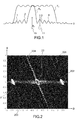
- the figure 1 illustrates the ambiguous side lobes of a simultaneous multiple-emission radar.
- the term "ambiguity function" is associated with a function that depends on at least two variables, distance and Doppler, for example.
- the figure 1 only describes one variable. In other words, the figure 1 describes the phenomenon with respect to the angle.
- the figure 2 below will describe more fully the phenomenon that actually plays on angle and distance.
- the figure 1 shows the amplitude of the emission beam Tx corresponding to an antenna sub-network, as a function of the angle ⁇ .
- the width of the beam depending on the size of the antenna sub-network, has a given width.
- the figure 1 also shows a receiving beam Rx in a direction defined by an angle ⁇ 0 , narrower.
- the multiple simultaneous transmission consists in transmitting different signals, a signal being associated with each sub-network that transmits from a given position in the antenna. These signals combine in space to provide a global signal that differs from one direction to another. The signal in a given direction results from a combination of signals from different subnets. The signal in another direction results from another combination of the same signals from different subnets.
- the processing performs a filtering adapted to the signal associated with this direction.
- the signals of the other directions are all from the same elementary signals.
- the filter adapted to the direction ⁇ 0 does not produce a perfect zero when it receives a signal in a other direction.
- This reception level corresponds to a secondary lobe 1, 2, 3, 4.
- the figure 1 illustrates the disadvantages of these side lobes. Indeed, a target 11 of large radar equivalent area (SER), present in a secondary lobe, can be detected as a low SER target present in the main reception lobe.
- SER radar equivalent area
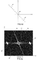
- the figure 2 presents, for a simultaneous multiple transmission code, the main lobe 20 in reception flanked by two secondary lobes 201, 202 in the range-angle range, the abscissas representing the distance to the target and the ordinates representing the reception angle, that is, the direction.
- the coding used to get as close as possible to the objective of elimination or at least strong reduction of the sidelobes, however reveals secondary lobes that are too high in certain zones (angle-direction) 203, 204, 205.
- the figure 3 illustrates a case corresponding to some codes which make it possible to approach the constraints on the sidelobes but at the price of a main lobe 300 strongly widened thus non discriminating.
- the Figures 1 to 3 illustrate the limits of multiple simultaneous emissions according to the prior art.
- the Figures 4a to 4d illustrate the principle of the invention using a particular and simple case.
- the solution according to the invention consists in transmitting not a single multiple transmission code but successively different codes, from one burst to another, and combine the responses obtained using a non-linear processing. It is possible to predict that the code does not vary between two successive bursts but among more than 2 bursts, not necessarily successive.
- the figure 4a has an antenna array 41 comprising, for example, eight antenna subnetworks 42.
- An antenna subnetwork may consist of a single antenna or a plurality of elementary antennas or antenna elements, radiating elements for example . These can be aligned.
- Each subnet issues according to a code.
- a code is assigned to each subnet 42.
- Each code is assigned to a subnet and to one.
- the figure 4a illustrates the coding of the emission for a burst of order M.
- first sub-network A 1 transmits according to a code C 1
- a second sub-network A 2 transmits according to a code C 2 and so on until the last sub-network A 8 which transmits according to a code C 8 .
- a code Ci corresponds to the allocation of a sub-frequency band 43, to a sub-network.
- the figure 4b shows the ambiguity function of the received signals corresponding to the emission of the figure 4a , represented in the range-angle range.
- the main lobe 44 is located at the origin of the axes.
- the side lobes 45 are aligned on each side of this main lobe 44 at a distance that increases linearly as a function of the angle ⁇ .
- the figure 4c illustrates the coding of the emission at the next burst, M + 1, for the same network as that of the figure 4a .
- the assignment of the codes Ci that is to say the sub-bands 43, with respect to the position of the sub-networks is reversed. Consequently, the first subnet A 1 transmits according to the code C 8 , the second subnet A 2 according to the code C 7 and so on, the eighth subnet A 8 emitting according to the code C1.
- the figure 4d shows the ambiguity function of the received signals corresponding to the emission of the figure 4c in the same range-angles range as that of the figure 4b .
- the alignment is oriented differently, it is symmetrical to the previous alignment with respect to the axis of the angles.
- the code of the burst M + 2 is the same as for the burst M, the code of the burst M + 3 being the same as that of the burst M + 1 And so on.
- the invention uses a principle similar to that used to remove ambiguities distance-doppler.
- the emission of several bursts with different ambiguities is carried out and then the association of the signals of the different bursts by nonlinear processing.
- the simplest and most commonly used treatment requires detection in the same distance-doppler cell over at least two bursts.
- the The simplest treatment requires detection in the same angle-distance-doppler cell over at least two bursts.
- the succession of different multiple emissions has the advantage of being very well combined with the variation of ambiguities distance and Doppler from burst to burst. This is based on a variation, from burst to burst, of the recurrence period of recurrence and possibly of the emission frequency.
- the solution proposed by the invention is to vary, in addition, the simultaneous multiple emission code as illustrated by the simple case of Figures 4a to 4d .
- the combination bursts processing, in order to suppress the sidelobes, may remain unchanged once the filters adapted to the codes emitted by each burst have been carried out. This treatment involves the detection of at least two bursts in the same angle-distance-doppler cell.
- compressed sensing It is thus possible to use compressed acquisition type treatments known elsewhere according to the English expression "compressed sensing". These "compressed sensing" type of processing make it possible to build a signal from a reduced number of measurements.
- the detection signal of a target is constructed from the measurements made in each direction for the successive multiple transmission codes.
- the invention thus notably realizes, in a simultaneous multiple-emission radar, the emission of different burst burst codes and effects the association of the different bursts by a non-linear processing, for example of the "2 on N” type, " K on N, "compressed sensing", Capon or Maximum likelihood.
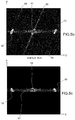
- the figures 5a , 5b and 5c illustrate a result obtained by the implementation of the invention.
- several transmission elements each transmit several codes successively, thus obtaining a succession of multiple simultaneous transmissions according to different codes.
- the succession of codes is established on two bursts.
- the figure 5a illustrates the functions of ambiguities for a first code sent in the burst of order M and the figure 5b illustrates the ambiguity functions for a second code transmitted in the burst of order M + 1.
- These ambiguity functions corresponding to secondary lobes are represented in the angle-distance domain.
- the figure 5a has a main lobe 51 and two first side lobes 52, 53 and a multitude of secondary lobes along three lines 54 passing through the previous lobes and oriented in the same direction.
- the figure 5b has the main lobe 51 and the first two secondary lobes 52, 53 and a multitude of secondary lobes along three lines 55 passing through these three lobes 51,52, 53 and oriented in another direction.
- FIG. 5a and 5b corresponds to the emission of two successive codes.
- a "2 out of 2" criterion is to take, at each point, the 2nd largest signal among the 2 available signals, that is to say to take the minimum signal.
- the figure 5c illustrates the effectiveness of the invention. It can indeed be seen that the invention greatly reduces the angle-distance range where a strong echo can disturb the detection of a weak echo. In the example of the figure 5c it appears that the residual lobes 57 are almost all on the distance axis. It is possible to solve these side lobes according to the state of the art.
- the basic treatment for suppressing side lobes from one burst to another is of type "K on N".
- We can implement two chains of association of the signals, one for the detection of fast targets, with K 2, and the other for the detection of slow targets, with K> 2.
- code families are used to easily obtain the operational objective. It is thus possible to choose a constraint that imposes few or localized secondary lobes, such as the secondary lobes 54 and 55 of the figures 5a and 5b , accepting that they are relatively high. Being few and localized, their suppression by a K on N criterion is effective and does not affect the detection of other targets. Codes satisfying this constraint are numerous and easy to synthesize. Some examples will be given later.
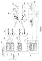
- the figure 6 illustrates a possible embodiment of a radar according to the invention.
- the equipment needed to emit multiple emissions different from one burst to another is essentially the same as for a single multiple issue code. In particular, it is necessary to provide for the digital memorization of the codes and their commands, which is simple to implement.
- the radar comprises an antenna consisting of Q transmit subarrays A 1 , A 2 ... A Q.
- Each sub-network has a signal generator 611, 612 ... 61Q, for example programmable, capable of emitting a different emission characteristic burst burst.
- An amplifier 621, 622, 62Q amplifies the signals from the generators 611, 612 ... 61Q before passing through the sub-networks.
- a local oscillator 10 provides a basic frequency to the frequency generators.
- the signal generators are controlled by control means 63 memorizing the different codes assigned to each sub-network A 1 , ... A Q for each burst.
- These storage means and commands codes are for example integrated in the radar processing means.
- the transmission comprises three successive encodings 67, instead of two in the example of Figures 5a to 5d .
- the storage means 63 must therefore at least memorize 3xQ different codes.
- the antenna thus emits a succession of simultaneous multiple signals, in a period of three bursts.
- the radar receives a succession of 68 target responses.
- a signal 681 corresponding to the coding of the burst M is received, a signal 682 corresponding to the coding of the burst M + 1 and a signal 683 corresponding to the coding of the burst M + 2.
- a second target 60 ' another set of signals 681', 682 ', 683' is received.
- the radar comprises at least one AR antenna as well as reception means 64, 65 comprising at least one low noise amplifier 64 and a digital receiver per antenna sub-network.
- the Figures 7a to 7d illustrate examples of space coding, by simultaneous multiple transmissions, by examples of frequency allocation to antenna sub-networks distributed over a single axis.
- the allocated frequency subbands are represented according to the position of the subnetworks. More particularly, the allocated frequencies are represented by squares 71, 72, 73, 74. The dimensions of each square represent the frequency sub-band along the ordinate axis and the dimension of the sub-network along the abscissa axis. These squares form elements of a matrix with a single element per row and column.
- the figure 7a corresponds to a coding similar to that of the figure 4a .
- the frequencies increase linearly with the position of the subnets.
- the squares 72 of the figure 7b are regularly aligned according to three increasing ramps shifted in frequency.
- the squares 73 are aligned regularly according to three decreasing ramps frequency shifted.
- the squares 74 are grouped in pairs, the pairs being themselves regularly aligned in decreasing ramps.
- a pair consists of two contiguous squares along one of their diagonals. Many other arrangements of squares, and therefore other coding by sub-network frequency allocation, are of course possible.
- the invention has been described for simultaneous multiple-emission radars.
- the invention can also advantageously be applied for active sonars operating according to the same principle of multiple transmissions.
Landscapes
- Engineering & Computer Science (AREA)
- Radar, Positioning & Navigation (AREA)
- Remote Sensing (AREA)
- Computer Networks & Wireless Communication (AREA)
- Physics & Mathematics (AREA)
- General Physics & Mathematics (AREA)
- Radar Systems Or Details Thereof (AREA)
Description
La présente invention concerne un système de détection à émissions multiples simultanées. Elle se rapporte également à un procédé de détection utilisant les émissions multiples simultanées.The present invention relates to a multiple simultaneous emission detection system. It also relates to a detection method using simultaneous multiple transmissions.
L'invention s'applique notamment dans le domaine des radars à émissions multiples simultanées encore appelés radars MIMO (« Multiple Input Multiple Output ») ou radars MISO (« Multiple Input Single Output »). Il peut s'agir de radars terrestres, navals, aéroportés ou spatiaux. L'invention peut également s'appliquer aux sonars actifs.The invention applies in particular in the field of multiple simultaneous emission radars also called MIMO ("Multiple Input Multiple Output") radars or MISO ("Multiple Input Single Output") radars. It can be terrestrial, naval, airborne or space-based radars. The invention can also be applied to active sonars.
Parmi les fonctions diverses d'un radar, une fonction est de détecter des objets lents et de faible réflectivité, comme des drones notamment. Pour détecter des objets lents en présence de fouillis, il faut avoir une bonne résolution Doppler donc une grande durée d'observation cohérente. Pour conserver une bonne précision angulaire, une solution consiste à employer un faisceau d'émission élargi et une grappe de faisceaux de réception qui couvre l'ensemble du faisceau d'émission. Dans une solution classique on élargit le faisceau par une loi de phase. Cependant cette solution ne permet pas d'obtenir l'isolation nécessaire entre la cible recherchée de faible réflectivité et de faible vitesse, par exemple un drone, et les véhicules au sol, de même vitesse et de réflectivité nettement plus forte. Une autre solution consiste à élargir le faisceau par émissions multiples simultanées ; cette solution est décrite ci-dessous. On verra qu'elle ne répond que partiellement au besoin, en effet certains lobes secondaires peuvent être réduits mais ils restent encore trop élevés ou en trop grande quantité.Among the various functions of a radar, a function is to detect slow objects and low reflectivity, such as drones in particular. To detect slow objects in the presence of clutter, it is necessary to have a good Doppler resolution so a consistent long observation time. In order to maintain good angular accuracy, one solution is to use an expanded transmit beam and a receive beam cluster that covers the entire transmit beam. In a conventional solution, the beam is widened by a phase law. However, this solution does not provide the necessary insulation between the desired target of low reflectivity and low speed, such as a drone, and ground vehicles, the same speed and much stronger reflectivity. Another solution is to widen the beam by simultaneous multiple broadcasts; this solution is described below. It will be seen that it responds only partially to the need, indeed some side lobes can be reduced but they are still too high or too large.
L'émission multiple simultanée, encore appelée émission colorée, consiste à émettre des signaux différents en fonction des sous-réseaux de l'antenne d'émission, et à réaliser ainsi un codage spatio-temporel de l'espace. Ces signaux se combinent dans l'espace selon des jeux de phase ou des retards qui dépendent de la direction visée. Il en résulte un signal global qui diffère d'une direction à l'autre. A la réception, pour détecter un signal issu d'une direction donnée, le traitement effectue un filtrage adapté au signal associé à cette direction. Ce filtre n'est pas adapté aux signaux issus des autres directions puisque le signal n'est plus le même dans ces autres directions. Cependant les signaux des différentes directions sont tous issus des mêmes signaux élémentaires. Il en résulte une corrélation qui fait que le filtre adapté à une direction ne produit pas un zéro parfait lorsqu'il reçoit un signal provenant d'une autre direction. Ce niveau correspond à un lobe secondaire de la fonction d'ambiguïté.Simultaneous multiple emission, also called color transmission, consists in transmitting different signals depending on the subnetworks of the transmitting antenna, and thus performing a spatiotemporal coding of the space. These signals combine spatially with phase games or delays that depend on the intended direction. The result is an overall signal that differs from one direction to the other. At the reception, to detect a signal coming from a given direction, the processing performs a filtering adapted to the signal associated with this direction. This filter is not adapted to signals from other directions since the signal is no longer the same in these other directions. However, the signals of the different directions are all from the same elementary signals. This results in a correlation that makes the one-directional filter do not produce a perfect zero when it receives a signal from another direction. This level corresponds to a secondary lobe of the ambiguity function.
Des analyses effectuées sur une grande variété de codes montrent que la plupart des codes analysés produisent des lobes secondaires dont le niveau dépasse le niveau souhaité dans certaines zones de l'espace angle-distance-Doppler. Les rares codes qui atteignent presque l'objectif de réduction de niveau élargissent significativement le lobe principal, ce qui les rend finalement peu utiles en raison du manque de discrimination que cela entraîne. En conclusion, aucun des codes d'émissions multiples simultanées analysés ne satisfait le besoin opérationnel.Analyzes performed on a wide variety of codes show that most of the codes analyzed produce secondary lobes whose level exceeds the desired level in certain areas of the angle-distance-Doppler space. The few codes that almost reach the goal of downsizing significantly widen the main lobe, making them ultimately of little use because of the lack of discrimination that entails. In conclusion, none of the simultaneous multiple emissions codes analyzed satisfies the operational requirement.
Un problème à résoudre pour ces radars de type MIMO ou MISO est donc la réduction des lobes secondaires de la fonction d'ambiguïté angle-distance-Doppler.A problem to be solved for these MIMO or MISO type radars is therefore the reduction of the secondary lobes of the angle-distance-Doppler ambiguity function.
Un document
Un document
Un document
Un but de l'invention est notamment de réduire le plus possible les lobes secondaires de la fonction d'ambiguïté notamment d'un radar à émissions multiples simultanées. A cet effet, l'invention a pour objet un système de détection à émissions multiples simultanées comportant une antenne composée de sous-réseaux d'émission éclairant une même zone de l'espace et au moins un sous-réseau de réception, chaque sous-réseau ayant une position donnée dans ledit réseau, chaque sous-réseau d'émission émettant un signal ayant une caractéristique propre, l'ensemble des caractéristiques propres à chaque sous-réseau formant le code d'émissions multiples simultanées, la détection de cibles étant réalisée par l'émission d'une suite de rafales d'émissions multiples, ladite suite comportant au moins deux codes d'émission différents, des échos étant présents dans lobe principal et dans des lobes secondaires de la fonction d'ambiguïté, ledit système :
- émettant des codes différents parmi au moins deux rafales, ladite émission conservant le lobe principal de la fonction d'ambiguïté mais orientant lesdits lobes secondaires de ladite fonction d'ambiguïté dans des directions différentes de rafale à rafale ;
- détectant les signaux issus de chaque direction ;
- effectuant l'association des différents signaux détectés dans chaque direction pour lesdites au moins deux rafales, ladite association réduisant le niveau des échos présents dans lesdits lobes secondaires, variables de rafale à rafale, de la fonction d'ambiguïté.
- emitting different codes among at least two bursts, said transmission retaining the main lobe of the ambiguity function but orienting said secondary lobes of said ambiguity function in different directions of burst gust;
- detecting signals from each direction;
- effecting the association of the different signals detected in each direction for said at least two bursts, said association reducing the level of the echoes present in said sidelobes, gust burst variables, of the ambiguity function.
Dans un mode de réalisation particulier, lesdits au moins deux codes d'émission sont consécutifs. Lesdits au moins deux codes sont par exemple répétés à l'intérieur de ladite suite de rafales.In a particular embodiment, said at least two emission codes are consecutive. Said at least two codes are for example repeated within said series of bursts.
L'émission comportant N codes différents, un par rafale, l'association est par exemple réalisée selon un critère « 2 sur N » ou selon un critère « K sur N », K étant supérieur à 2.The transmission comprising N different codes, one by burst, the association is for example carried out according to a criterion "2 on N" or according to a criterion "K on N", K being greater than 2.
L'association se fait par exemple selon un traitement du type « Compressed Sensing » ou selon un traitement du type maximum de vraisemblance.The association is done for example according to a treatment of the type "Compressed Sensing" or according to a treatment of the maximum likelihood type.
Un code d'émissions multiples simultanées est par exemple réalisé en attribuant à chaque sous-réseau d'émission une sous-bande de fréquence. Dans un mode de réalisation possible, les centres de phase desdits sous-réseaux d'émission sont alignés selon un axe.A code of simultaneous multiple transmissions is for example made by allocating to each transmission subnetwork a frequency sub-band. In one possible embodiment, the phase centers of said transmission subareas are aligned along an axis.
Ledit système comportant plusieurs sous-réseaux de réception, lesdits sous-réseaux ne sont pas colocalisés, chaque sous-réseau de réception recevant les signaux issus des différentes émissions produites par lesdits sous-réseaux d'émission.Said system comprising several reception subnetworks, said subnetworks are not collocated, each reception subnetwork receiving the signals from the different transmissions produced by said transmission subnetworks.
L'invention a également pour objet un procédé de détection à émissions multiples simultanées utilisant une antenne composée de sous-réseaux d'émission éclairant une même zone de l'espace et au moins un sous-réseau de réception, chaque sous-réseau ayant une position donnée dans ledit réseau, procédé dans lequel :
- on attribue à chaque sous-réseau d'émission un signal d'émission ayant une caractéristique propre, l'ensemble des caractéristiques propres à chaque sous-réseau formant le code d'émissions multiples simultanées, la détection de cibles étant réalisée par l'émission d'une suite de rafales d'émissions multiples, ladite suite comportant au moins deux codes d'émission différents, des échos étant présents dans lobe principal et dans des lobes secondaires de la fonction d'ambiguïté,
- on émet des codes différents parmi au moins deux rafales, ladite émission conservant le lobe principal de la fonction d'ambiguïté mais orientant les lobes secondaires de ladite fonction d'ambiguïté dans des directions différentes de rafale à rafale ;
- on détecte les signaux issus de chaque direction;
- on effectue l'association des différents signaux détectés dans chaque direction pour lesdites au moins deux rafales, ladite association réduisant le niveau des échos présents dans les lobes secondaires, variables de rafale à rafale, de la fonction d'ambiguïté.
- each transmission sub-network is assigned a transmission signal having a characteristic of its own, the set of characteristics specific to each sub-network forming the simultaneous multiple-emission code, the detection of targets being carried out by the transmission a sequence of multiple emission bursts, said sequence comprising at least two different emission codes, echoes being present in the main lobe and in secondary lobes of the ambiguity function,
- different codes are emitted from at least two bursts, said emission retaining the main lobe of the ambiguity function but orienting the secondary lobes of said ambiguity function in different directions from burst to burst;
- the signals coming from each direction are detected;
- the combination of the different signals detected in each direction for the said at least two bursts is performed, the said association reducing the level of the echoes present in the side lobes, gust burst variables, of the ambiguity function.
D'autres caractéristiques et avantages de l'invention apparaîtront à l'aide de la description qui suit, faite en regard de dessins annexés qui représentent :
- la
figure 1 , une illustration des lobes secondaires d'ambiguïté d'un radar à émissions multiples simultanées ; - la
figure 2 , un exemple de lobe principal et de lobes secondaires correspondant à un code d'émissions multiples simultanées ; - la
figure 3 , un exemple de lobe principal et de lobes secondaires correspondant à un code d'émissions multiples simultanées permettant de réduire les lobes secondaires ; - les
figures 4a à 4d , une illustration du principe de l'invention; - les
figures 5a à 5c , une illustration d'un résultat obtenu par l'invention ; - la
figure 6 , un exemple de réalisation possible d'un radar selon l'invention ; - les
figures 7a à 7b , des exemples de codage d'émissions multiples simultanées pouvant être mises en oeuvre par l'invention.
- the
figure 1 , an illustration of the ambiguous side lobes of a simultaneous multiple-emission radar; - the
figure 2 an example of a main lobe and secondary lobes corresponding to a simultaneous multiple emission code; - the
figure 3 an example of a main lobe and secondary lobes corresponding to a simultaneous multiple emission code for reducing side lobes; - the
Figures 4a to 4d an illustration of the principle of the invention; - the
Figures 5a to 5c an illustration of a result obtained by the invention; - the
figure 6 an example embodiment of a radar according to the invention; - the
Figures 7a to 7b examples of simultaneous multiple emission coding that can be implemented by the invention.
La
Dans une structure selon l'art antérieur, plusieurs éléments d'émission émettent chacun un signal caractéristique. Un ou plusieurs éléments de réception effectuent un traitement qui exploite la connaissance du signal rayonné en fonction de la direction, donc du codage de l'espace.In a structure according to the prior art, several transmission elements each emit a characteristic signal. One or more receiving elements perform a processing which exploits the knowledge of the radiated signal as a function of the direction, therefore of the coding of the space.
Plus particulièrement, la
La
A la réception, pour détecter un signal issu d'une direction donnée θ0, le traitement effectue un filtrage adapté au signal associé à cette direction. Cependant les signaux des autres directions sont tous issus des mêmes signaux élémentaires. Par un effet de corrélation, le filtre adapté à la direction θ0 ne produit pas un zéro parfait lorsqu'il reçoit un signal dans une autre direction. Ce niveau de réception correspond à un lobe secondaire 1, 2, 3, 4. La
La
La
Les
La
Chaque sous-réseau émet selon un code. Un code est affecté à chaque sous-réseau 42. Chaque code est affecté à un sous-réseau et à un seul. La
La
La
La
On peut alors par un traitement adapté supprimer les lobes secondaires 45, 47 qui ne sont pas positionnés aux même endroits d'une rafale à l'autre et ne conserver que le lobe principal 44, 46. Dans un cas de mise en oeuvre où les changements de codes se font d'une rafale à l'autre, le code de la rafale M+2 est le même que pour la rafale M, le code de la rafale M+3 étant le même que celui de la rafale M+1 et ainsi de suite.It is then possible, by a suitable treatment, to eliminate the
Avantageusement, l'invention utilise un principe semblable à celui en usage pour lever les ambiguïtés distance-Doppler. Dans ce dernier cas, on effectue l'émission de plusieurs rafales avec des ambiguïtés différentes puis l'association des signaux des différentes rafales par un traitement non linéaire. Le traitement le plus simple et le plus couramment utilisé demande la détection, dans une même cellule distance-Doppler sur au moins deux rafales. Dans le cas des émissions multiples successives selon l'invention, le traitement le plus simple demande la détection dans une même cellule angle-distance-Doppler sur au moins deux rafales.Advantageously, the invention uses a principle similar to that used to remove ambiguities distance-doppler. In the latter case, the emission of several bursts with different ambiguities is carried out and then the association of the signals of the different bursts by nonlinear processing. The simplest and most commonly used treatment requires detection in the same distance-doppler cell over at least two bursts. In the case of successive multiple transmissions according to the invention, the The simplest treatment requires detection in the same angle-distance-doppler cell over at least two bursts.
La succession d'émissions multiples différentes présente l'avantage de très bien se combiner avec la variation d'ambiguïtés distance et Doppler de rafale à rafale. Celle-ci s'appuie sur une variation, de rafale à rafale, de la période de récurrence de récurrence et éventuellement de la fréquence d'émission. La solution proposée par l'invention consiste à faire varier, en plus, le code d'émission multiple simultanée comme illustré par le cas simple des
L'exemple illustré par les
On peut ainsi utiliser des traitements de type acquisition comprimée connus par ailleurs selon l'expression anglaise « compressed sensing ». Ces traitement de type « compressed sensing » permettent de construire un signal à partir d'un nombre réduit de mesures. Dans l'application à la présente association, on construit le signal de détection d'une cible à partir des mesures effectuées dans chaque direction, pour les codes d'émission multiple successifs.It is thus possible to use compressed acquisition type treatments known elsewhere according to the English expression "compressed sensing". These "compressed sensing" type of processing make it possible to build a signal from a reduced number of measurements. In the application to the present association, the detection signal of a target is constructed from the measurements made in each direction for the successive multiple transmission codes.
Ces traitements appliqués aux formes d'ondes proposées permettent d'obtenir des performances supérieures à celles du critère 2 sur N ou même du critère K sur N. Ils optimisent la détection simultanée d'un ensemble de cibles. Des exemples de traitement du type « compressed sensing » sont notamment décrit dans le document
On peut aussi envisager des traitements adaptatifs, par exemple du type Capon ou maximum de vraisemblance.It is also possible to envisage adaptive treatments, for example of the capon or maximum likelihood type.
L'invention réalise donc notamment, dans un radar à émissions multiples simultanées, l'émission de codes différents de rafales à rafale et effectue l'association des différentes rafales par un traitement non linéaire, par exemple du type « 2 sur N », « K sur N », « compressed sensing », Capon ou Maximum de vraisemblance.The invention thus notably realizes, in a simultaneous multiple-emission radar, the emission of different burst burst codes and effects the association of the different bursts by a non-linear processing, for example of the "2 on N" type, " K on N, "compressed sensing", Capon or Maximum likelihood.
Les
La
En réception, un ou plusieurs éléments de réception effectuent:
- un traitement qui exploite la connaissance du signal rayonné en fonction de la direction pour chaque émission multiple simultanée, au moyen d'un filtrage adapté . Ce traitement peut être effectué en sortie de la fonction de Formation de Faisceau par le Calcul (avec un filtre adapté par faisceau, dont les coefficients sont associés à la direction du faisceau), ou être effectué avant la Formation de Faisceau par le Calcul (avec un ensemble de filtres adaptés, chacun étant associé à l'une des directions des faisceaux que produit la FFC);
- Puis un traitement qui associe les réponses issues des émissions successives, ce traitement étant par exemple de type « 2 sur N », « K sur N » , « Compressed sensing », « Capon » ou « Maximum de Vraisemblance ».
- a processing which exploits the knowledge of the signal radiated as a function of the direction for each simultaneous multiple transmission, by means of a matched filtering. This processing can be performed at the output of the Beam Formation function by the Calculation (with a beam-adapted filter, the coefficients of which are associated with the beam direction), or be performed before the Beam Formation by the Calculation (with a set of adapted filters, each associated with one of the beam directions produced by the FFC);
- Then a treatment that combines the responses from successive emissions, this treatment being for example of the type "2 of N", "K on N", "Compressed sensing", "Capon" or "Maximum Likelihood".
L'exemple des
La fonction d'ambiguïté issue de cette association est illustrée par la
La
Le traitement de base de suppression des lobes secondaires d'une rafale à l'autre est de type « K sur N ». La valeur K = 2 est habituellement utilisée pour les cibles rapides tandis qu'une valeur supérieure est mieux adaptée pour la détection de cibles lentes et de faible réflectivité, étant en première trace de distance et vitesse, ils ne sont pas occultés par les éclipses distance et vitesse, et sont donc visibles sur les N rafales. On peut mettre en oeuvre deux chaînes d'association des signaux, l'une pour la détection de cibles rapides, avec K = 2, et l'autre pour la détection des cibles lentes, avec K > 2.The basic treatment for suppressing side lobes from one burst to another is of type "K on N". The value K = 2 is usually used for fast targets while a higher value is better suited for the detection of slow targets and low reflectivity, being in first trace distance and speed, they are not obscured by eclipses distance and speed, and are therefore visible on the N bursts. We can implement two chains of association of the signals, one for the detection of fast targets, with K = 2, and the other for the detection of slow targets, with K> 2.
Plusieurs familles de codes d'émission multiple simultanée peuvent être utilisées. De préférence, on utilise des familles de codes permettant d'obtenir facilement l'objectif opérationnel. On peut ainsi choisir une contrainte qui impose des lobes secondaires peu nombreux ou localisés, comme par exemple les lobes secondaires 54 et 55 des
Les figures qui suivent présentent des modes de réalisations possibles pour la génération des signaux et le traitement numérique des échos issus des émissions simultanées successives.The following figures show possible embodiments for signal generation and digital processing of echoes from successive simultaneous transmissions.
La
L'antenne émet ainsi une succession de signaux multiples simultanés, selon une période de trois rafales.The antenna thus emits a succession of simultaneous multiple signals, in a period of three bursts.
A partir de cette succession de signaux d'émissions multiples simultanés, le radar reçoit une succession 68 de réponses de cibles. Pour une première cible 60 on reçoit un signal 681 correspondant au codage de la rafale M, un signal 682 correspondant au codage de la rafale M+1 et un signal 683 correspondant au codage de la rafale M+2. Pour une deuxième cible 60', on reçoit une autre série de signaux 681', 682', 683'.From this succession of simultaneous multiple transmit signals, the radar receives a succession of 68 target responses. For a
A la réception, le radar comporte au moins une antenne AR ainsi que des moyens de réception 64, 65 comprenant au moins un amplificateur faible bruit 64 et un récepteur numérique par sous-réseau d'antenne.At the reception, the radar comprises at least one AR antenna as well as reception means 64, 65 comprising at least one
Les moyens de réception 65 effectuent notamment les fonctions suivantes,
- Formation de faisceau par le calcul, capable de former une grappe de faisceaux recouvrant l'ensemble du diagramme d'émission Tx ;
- Compression d'impulsions effectuant, dans chaque faisceau formé,
un filtre adapté 66 au signal rayonné dans la direction du faisceau ; - Filtrage Doppler produisant un ensemble de filtres étroits ;
- Régulation de fausses alarmes associant TFAC (Taux de Fausse Alarme Constant, estimation sur les axes distance et Doppler) et carte de fouillis (estimation de balayage à balayage dans chaque cellule angle-distance, à Doppler faible) ;
- Détection par comparaison à un seuil ;
- Dépliement distance-Doppler ;
Association 69 des signaux 70 détectés en sortie des filtres 66 pour les trois rafales, par exemple en deux types d'association :- Selon un critère « 2 sur N » en vue de détecter les cibles rapides ;
- Selon un critère « K sur N » en vue de détecter les cibles lentes ;
d'autres critères pouvant être utilisés, seuls subsistant en sortie de l'association la ou les échos 600 de cibles présentes dans la direction des filtres adaptés ;
- Extraction des données associée à chaque association par :
- Regroupement des détections voisines en un amas de détections
- Calcul de la position moyenne de chaque amas
- Regroupement des informations en un plot
- Eventuellement un pistage réalisant :
- Un chaînage des plots de tour à tour ;
- Un calcul des paramètres de trajectoire.
- Beam formation by calculation, capable of forming a bundle of beams covering the entire Tx emission diagram;
- Pulse compression effecting, in each formed beam, a
filter 66 adapted to the signal radiated in the direction of the beam; - Doppler filtering producing a set of narrow filters;
- False alarm regulation associating TFAC (Constant Alarm Fault Rate, distance and Doppler axis estimation) and clutter map (scanning sweep estimate in each angle-distance cell, low Doppler);
- Detection by comparison with a threshold;
- Unfolding distance-Doppler;
-
Association 69 of thesignals 70 detected at the output of thefilters 66 for the three bursts, for example in two types of association:- According to a "2 on N" criterion for detecting fast targets;
- According to a "K on N" criterion for detecting slow targets;
other criteria that can be used, only remaining at the output of the association or echoes 600 of targets present in the direction of the adapted filters;
- Extraction of the data associated with each association by:
- Grouping neighboring detections into a pile of detections
- Calculation of the average position of each cluster
- Grouping information into a plot
- Possibly a tracking realizing:
- A chaining of the studs from one turn to another;
- A calculation of the trajectory parameters.
Il est possible de modifier l'ordre des deux premières fonctions ci-dessus qui deviennent alors :
- Compression d'impulsions adaptées aux directions recouvrant l'ensemble du diagramme d'émission Tx ;
- Formation de faisceau par le calcul formant, pour chaque sortie de compression d'impulsion, le faisceau associé à la direction.
- Compression of pulses adapted to the directions covering the whole emission diagram Tx;
- Beam formation by calculating, for each pulse compression output, the beam associated with the direction.
Quelques variantes de réalisation peuvent être mises en oeuvre, en particulier on peut prévoir un exemple de réalisation comportant une ou plusieurs des caractéristiques suivantes :
- L'antenne d'émission comporte un générateur par élément rayonnant, ceci revient à ce que chaque sous-réseau d'émission soit un seul élément d'antenne ;
- L'antenne d'émission dispose de sous-réseaux dont les centres sont alignés selon un seul axe, par exemple sous forme de poutres verticales espacées sur l'axe horizontal ou de poutres horizontales espacées sur l'axe vertical ;
- Les sous-réseaux d'antenne de réception ne sont pas localisés au même endroit et chaque sous-réseau de réception reçoit les échos issus des différentes émissions, le traitement qui rassemble les signaux issus des sous-réseaux distants pouvant alors se faire de façon cohérente ou non cohérente, l'exemple de la
figure 6 présente un seul sous-réseau de réception mais il est bien sûr possible d'en prévoir plusieurs ; - La grappe de faisceaux de réception comporte des faisceaux resserrés par exemple d'un facteur racine de 2 sur chaque axe pour anticiper le gain en résolution angulaire apporté par l'émission multiple simultanée ;
- L'antenne de réception comporte un récepteur par élément rayonnant, ceci revenant à ce que chaque sous-réseau de réception soit un seul élément d'antenne ;
- La compression d'impulsions effectue en parallèle plusieurs filtres, chacun adapté à une gamme de vitesses radiales. Ceci est notamment utile lorsque les codes sont sensibles au Doppler, codes qui peuvent être rendus intéressants en vue de la solution proposée ;
- Le filtrage Doppler peut ne pas être réalisé, pour une émission en rafales comportant une seule impulsion, ou comporter des filtres peu résolvants, pour des rafales comportant un faible nombre d'impulsions ;
- L'organe de régulation de fausse alarme effectue son estimation en s'appuyant sur les propriétés de chaque code émis, par exemple par une estimation sur une diagonale distance-angle ;
- L'association des rafales est effectuée selon un traitement « Compressed sensing », un seul traitement d'association peut alors convenir à la fois aux cibles lentes et aux cibles rapides ;
- L'association des rafales est effectué selon un traitement de type adaptatif, par exemple par une méthode des moindres carrés, Capon ou encore maximum de vraisemblance.
- The transmitting antenna comprises a generator per radiating element, this amounts to the fact that each transmission subnetwork is a single antenna element;
- The transmitting antenna has sub-networks whose centers are aligned along a single axis, for example in the form of vertical beams spaced on the horizontal axis or horizontal beams spaced on the vertical axis;
- The receiving antenna subnetworks are not located at the same location and each reception subnetwork receives the echoes from the different broadcasts, the processing that gathers the signals from the remote subnetworks can then be done in a coherent manner. or inconsistent, the example of the
figure 6 has only one receiving subnetwork but of course it is possible to provide more than one; - The reception beam cluster comprises beams, for example tightened by a root factor of 2 on each axis, in order to anticipate the gain in angular resolution brought by the multiple simultaneous emission;
- The receiving antenna comprises a receiver per radiating element, this being such that each receiving subnetwork is a single antenna element;
- The pulse compression performs in parallel several filters, each adapted to a range of radial speeds. This is particularly useful when the codes are Doppler sensitive, codes that can be made interesting for the proposed solution;
- Doppler filtering may not be performed, for burst transmission with a single pulse, or with poorly resolving filters, for bursts with a small number of pulses;
- The false alarm regulator performs its estimation based on the properties of each transmitted code, for example by an estimate on a diagonal distance-angle;
- The combination of bursts is carried out according to a "Compressed sensing" treatment, a single association treatment can then be suitable for both slow targets and fast targets;
- The combination of bursts is carried out according to an adaptive type treatment, for example by a least squares method, Capon or even maximum likelihood.
Les
La
L'invention a été décrite pour des radars à émissions multiples simultanées. L'invention peut également avantageusement s'appliquer pour des sonars actifs fonctionnant selon le même principe d'émissions multiples.The invention has been described for simultaneous multiple-emission radars. The invention can also advantageously be applied for active sonars operating according to the same principle of multiple transmissions.
Claims (19)
- Detection system with simultaneous multiple transmissions including an antenna (41) composed of transmission sub-arrays (42, A1, ... AQ) illuminating one and the same zone of the space and at least one reception sub-array (AR), each sub-array having a given position in said array, each transmission sub-array transmitting a signal having a specific characteristic, the set of characteristics specific to each sub-array forming the simultaneous multiple transmission code, the detection of targets being performed by the transmission of a series of bursts of multiple transmissions, said series including at least two different transmission codes, echoes being present in the main lobe (44, 46) and in the sidelobes (45, 47) of the ambiguity function, characterized in that said system:- transmits different codes (67) from among at least two bursts, said transmission preserving the main lobe of the ambiguity function but orienting said sidelobes of said ambiguity function in different directions from burst to burst;- detects the signals (68) originating from each direction;- carries out the aggregation (69) of the different signals (70) detected in each direction for said at least two bursts, said aggregation reducing the level of the echoes present in said sidelobes (45, 47) of the ambiguity function.
- Detection system according to Claim 1, characterized in that said at least two transmission codes are consecutive.
- Detection system according to any one of the preceding claims, characterized in that said at least two codes are repeated within said series of bursts.
- Detection system according to any one of the preceding claims, characterized in that, since the transmission includes N different codes, one per burst, the aggregation is performed according to a "2 of N" criterion.
- Detection system according to any one of the preceding claims, characterized in that since the transmission includes N different codes, one per burst, the aggregation is performed according to a "K of N" criterion, K being greater than 2.
- Detection system according to any one of the preceding claims, characterized in that the aggregation is made according to processing of the "Compressed Sensing" type.
- Detection system according to any one of the preceding claims, characterized in that the aggregation is made according to processing of the maximum likelihood type.
- Detection system according to any one of the preceding claims, characterized in that a simultaneous multiple transmission code is produced by attributing a frequency sub-band to each transmission sub-array (43).
- Detection system according to any one of the preceding claims, characterized in that the phase centres of said transmission sub-arrays (42, A1, ... AQ) are aligned on an axis.
- Detection system according to any one of the preceding claims, characterized in that including several reception sub-arrays (AR), said sub-arrays are not co-located, each reception sub-array receiving the signals originating from the different transmissions produced by said transmission sub-arrays.
- Detection system according to any one of the preceding claims, characterized in that the detection system is a radar.
- Detection method with simultaneous multiple transmissions using an antenna (41) composed of transmission sub-arrays (42, A1, ... AQ) illuminating one and the same zone of the space and at least one reception sub-array (AR), each sub-array having a given position in said array, a method in which to each transmission sub-array is attributed a transmission signal having a specific characteristic, the set of characteristics specific to each sub-array forming the simultaneous multiple transmission code, the detection of targets being performed by the transmission of a series of bursts of multiple transmissions, said series including at least two different transmission codes, echoes being present in the main lobe (44, 46) and in the sidelobes (45, 47) of the ambiguity function, characterized in that:- different codes (67) are transmitted from among at least two bursts, said transmission preserving the main lobe of the ambiguity function but orienting said sidelobes of said ambiguity function in different directions from burst to bu rst;- the signals (68) originating from each direction are detected;- the aggregation (69) is made of the different signals (70) detected in each direction for said at least two bursts, said aggregation reducing the level of the echoes present in said sidelobes (45, 47) of the ambiguity function.
- Detection method according to Claim 12, characterized in that said at least two transmission codes are consecutive.
- Detection method according to any one of Claims 12 and 13, characterized in that said at least two codes are repeated within said series of bursts.
- Detection method according to any one of Claims 12 to 14, characterized in that, since the transmission includes N different codes, one per burst, the aggregation is performed according to a "2 of N" criterion.
- Detection method according to any one of Claims 12 to 15, characterized in that since the transmission includes N different codes, one per burst, the aggregation is performed according to a "K of N" criterion, K being greater than 2.
- Detection method according to any one of Claims 10 and 13, characterized in that the aggregation is made according to processing of "Compressed Sensing" type.
- Detection method according to any one of Claims 12 to 17, characterized in that the aggregation is made according to processing of maximum likelihood type.
- Method according to any one of Claims 12 to 18, characterized in that a simultaneous multiple transmission code is performed by attributing a frequency sub-band (43) to each sub-array (42, A1, ... AQ).
Applications Claiming Priority (1)
| Application Number | Priority Date | Filing Date | Title |
|---|---|---|---|
| FR1301453A FR3007585B1 (en) | 2013-06-21 | 2013-06-21 | SIMULTANEOUS MULTI-EMISSION DETECTION SYSTEM AND DETECTION METHOD |
Publications (2)
| Publication Number | Publication Date |
|---|---|
| EP2816369A1 EP2816369A1 (en) | 2014-12-24 |
| EP2816369B1 true EP2816369B1 (en) | 2016-04-06 |
Family
ID=50064640
Family Applications (1)
| Application Number | Title | Priority Date | Filing Date |
|---|---|---|---|
| EP14171667.0A Active EP2816369B1 (en) | 2013-06-21 | 2014-06-09 | Detection system with multiple simultaneous emissions and detection method |
Country Status (6)
| Country | Link |
|---|---|
| EP (1) | EP2816369B1 (en) |
| CA (1) | CA2854620C (en) |
| ES (1) | ES2574489T3 (en) |
| FR (1) | FR3007585B1 (en) |
| IN (1) | IN2014DE01619A (en) |
| PL (1) | PL2816369T3 (en) |
Cited By (1)
| Publication number | Priority date | Publication date | Assignee | Title |
|---|---|---|---|---|
| FR3125888A1 (en) | 2021-07-30 | 2023-02-03 | Thales | METHOD FOR OPTIMIZING THE DETERMINATION OF THE DISTANCE OF A TARGET IN RELATION TO A PHASE ENCODED RADAR IN PULSE MODE |
Families Citing this family (1)
| Publication number | Priority date | Publication date | Assignee | Title |
|---|---|---|---|---|
| FR3088730B1 (en) | 2018-11-15 | 2022-03-11 | Thales Sa | Method for creating at least one virtual reception channel by using a radar antenna and radar system |
Family Cites Families (2)
| Publication number | Priority date | Publication date | Assignee | Title |
|---|---|---|---|---|
| US6977610B2 (en) * | 2003-10-10 | 2005-12-20 | Raytheon Company | Multiple radar combining for increased range, radar sensitivity and angle accuracy |
| FR2965362B1 (en) * | 2010-09-28 | 2013-08-09 | Thales Sa | RADAR HAVING HIGH ANGULAR COVERAGE, IN PARTICULAR FOR THE OBSTACLE AVOIDING FUNCTION ON AUTOPILOT AIRCRAFT |
-
2013
- 2013-06-21 FR FR1301453A patent/FR3007585B1/en not_active Expired - Fee Related
-
2014
- 2014-06-09 ES ES14171667.0T patent/ES2574489T3/en active Active
- 2014-06-09 PL PL14171667.0T patent/PL2816369T3/en unknown
- 2014-06-09 EP EP14171667.0A patent/EP2816369B1/en active Active
- 2014-06-16 IN IN1619DE2014 patent/IN2014DE01619A/en unknown
- 2014-06-18 CA CA2854620A patent/CA2854620C/en active Active
Cited By (1)
| Publication number | Priority date | Publication date | Assignee | Title |
|---|---|---|---|---|
| FR3125888A1 (en) | 2021-07-30 | 2023-02-03 | Thales | METHOD FOR OPTIMIZING THE DETERMINATION OF THE DISTANCE OF A TARGET IN RELATION TO A PHASE ENCODED RADAR IN PULSE MODE |
Also Published As
| Publication number | Publication date |
|---|---|
| CA2854620A1 (en) | 2014-12-21 |
| ES2574489T3 (en) | 2016-06-20 |
| FR3007585A1 (en) | 2014-12-26 |
| PL2816369T3 (en) | 2016-10-31 |
| CA2854620C (en) | 2021-05-25 |
| IN2014DE01619A (en) | 2015-06-19 |
| EP2816369A1 (en) | 2014-12-24 |
| FR3007585B1 (en) | 2015-06-05 |
Similar Documents
| Publication | Publication Date | Title |
|---|---|---|
| EP2834664B1 (en) | Radar with low interception probability | |
| EP2831615B1 (en) | Device for active and passive electromagnetic detection with a low likelihood of interception | |
| EP3047298B1 (en) | Method for detecting targets and associated multifunction radar | |
| EP2296007B1 (en) | Radar with beam agility, in particular for the function of detecting and avoiding obstacles | |
| EP2296006B1 (en) | Airborne radar with wide angular coverage, in particular for the function for detecting and avoiding obstacles | |
| FR2833356A1 (en) | Surface wave radar system for use in coastal area, has data processing system to process data representing receive signals to mitigate ionospheric clutter | |
| FR2948774A1 (en) | RADAR FOR DETECTING AIR TARGETS EQUIPPED WITH AN AIRCRAFT, IN PARTICULAR FOR THE AVOIDANCE OF OBSTACLES IN FLIGHT | |
| FR3010799A1 (en) | SYSTEM FOR DETECTING AND LOCATING IMMERSION OBJECTS FLOATING BETWEEN TWO WATERS, SUCH AS FROG MINES, AND ASSOCIATED METHOD | |
| FR2953297A1 (en) | Radar device for detecting intrusion of e.g. terrestrial vehicle, in sensitive area, has radar located on base, where deviation between emission frequencies of two radars is higher than half of addition of two spectral bands of one radar | |
| EP2816369B1 (en) | Detection system with multiple simultaneous emissions and detection method | |
| EP3198299B1 (en) | Radar detection method and radar implementing said method | |
| EP2631670B1 (en) | System and method of radar location. | |
| EP3654059B1 (en) | Method for creating at least one virtual reception channel through the use of a radar antenna and radar system | |
| EP2673651A1 (en) | Device for broadband reception by autotransposition and application to the detection and characterization of radioelectric emissions | |
| WO2005124386A1 (en) | Method of detecting and viewing low-power moving acoustic sources | |
| FR2901365A1 (en) | ENHANCED FRONTAL SONAR | |
| FR2998975A1 (en) | Method for filtering ambiguities in retrodiffused radar signal of multichannel radar system on-board aircraft, involves calculating filter to be applied to matrix to minimize power of unwanted echoes within retrodiffused radar signal | |
| EP1351333A2 (en) | Adaptive phased array antenna and radar using the same | |
| EP1233282B1 (en) | System with distributed transmit and receive antennas, in particular for radar with synthetic emission and beamforming | |
| EP4386442A1 (en) | Method for characterising a target for a radar or sonar type detection device with multiple electronic scanning | |
| FR3133678A1 (en) | Radar system and associated method for optimizing radar clutter elimination | |
| FR3040794A1 (en) | METHOD FOR TRACKING SATELLITE NAVIGATION SIGNALS | |
| EP2558881B1 (en) | Path-forming adaptive processing for active sonar | |
| FR3077695A1 (en) | DEVICE AND METHOD FOR TRANSMITTING / RECEIVING RADIO SIGNALS | |
| FR2840474A1 (en) | Ground observation multiple synthetic aperture radars having trajectory differences corrected using complex target sample modes from transmitter/receiver difference pairs using marker target placed same section radar wavelength trajectory |
Legal Events
| Date | Code | Title | Description |
|---|---|---|---|
| PUAI | Public reference made under article 153(3) epc to a published international application that has entered the european phase |
Free format text: ORIGINAL CODE: 0009012 |
|
| 17P | Request for examination filed |
Effective date: 20140609 |
|
| AK | Designated contracting states |
Kind code of ref document: A1 Designated state(s): AL AT BE BG CH CY CZ DE DK EE ES FI FR GB GR HR HU IE IS IT LI LT LU LV MC MK MT NL NO PL PT RO RS SE SI SK SM TR |
|
| AX | Request for extension of the european patent |
Extension state: BA ME |
|
| R17P | Request for examination filed (corrected) |
Effective date: 20150318 |
|
| RBV | Designated contracting states (corrected) |
Designated state(s): AL AT BE BG CH CY CZ DE DK EE ES FI FR GB GR HR HU IE IS IT LI LT LU LV MC MK MT NL NO PL PT RO RS SE SI SK SM TR |
|
| GRAP | Despatch of communication of intention to grant a patent |
Free format text: ORIGINAL CODE: EPIDOSNIGR1 |
|
| INTG | Intention to grant announced |
Effective date: 20160104 |
|
| GRAS | Grant fee paid |
Free format text: ORIGINAL CODE: EPIDOSNIGR3 |
|
| GRAA | (expected) grant |
Free format text: ORIGINAL CODE: 0009210 |
|
| AK | Designated contracting states |
Kind code of ref document: B1 Designated state(s): AL AT BE BG CH CY CZ DE DK EE ES FI FR GB GR HR HU IE IS IT LI LT LU LV MC MK MT NL NO PL PT RO RS SE SI SK SM TR |
|
| REG | Reference to a national code |
Ref country code: GB Ref legal event code: FG4D Free format text: NOT ENGLISH |
|
| REG | Reference to a national code |
Ref country code: AT Ref legal event code: REF Ref document number: 788377 Country of ref document: AT Kind code of ref document: T Effective date: 20160415 Ref country code: CH Ref legal event code: EP |
|
| REG | Reference to a national code |
Ref country code: IE Ref legal event code: FG4D Free format text: LANGUAGE OF EP DOCUMENT: FRENCH |
|
| REG | Reference to a national code |
Ref country code: DE Ref legal event code: R096 Ref document number: 602014001369 Country of ref document: DE |
|
| REG | Reference to a national code |
Ref country code: FR Ref legal event code: PLFP Year of fee payment: 3 |
|
| REG | Reference to a national code |
Ref country code: ES Ref legal event code: FG2A Ref document number: 2574489 Country of ref document: ES Kind code of ref document: T3 Effective date: 20160620 |
|
| REG | Reference to a national code |
Ref country code: LT Ref legal event code: MG4D Ref country code: NL Ref legal event code: MP Effective date: 20160406 |
|
| REG | Reference to a national code |
Ref country code: AT Ref legal event code: MK05 Ref document number: 788377 Country of ref document: AT Kind code of ref document: T Effective date: 20160406 |
|
| PG25 | Lapsed in a contracting state [announced via postgrant information from national office to epo] |
Ref country code: NL Free format text: LAPSE BECAUSE OF FAILURE TO SUBMIT A TRANSLATION OF THE DESCRIPTION OR TO PAY THE FEE WITHIN THE PRESCRIBED TIME-LIMIT Effective date: 20160406 |
|
| PG25 | Lapsed in a contracting state [announced via postgrant information from national office to epo] |
Ref country code: LT Free format text: LAPSE BECAUSE OF FAILURE TO SUBMIT A TRANSLATION OF THE DESCRIPTION OR TO PAY THE FEE WITHIN THE PRESCRIBED TIME-LIMIT Effective date: 20160406 Ref country code: IS Free format text: LAPSE BECAUSE OF FAILURE TO SUBMIT A TRANSLATION OF THE DESCRIPTION OR TO PAY THE FEE WITHIN THE PRESCRIBED TIME-LIMIT Effective date: 20160806 Ref country code: NO Free format text: LAPSE BECAUSE OF FAILURE TO SUBMIT A TRANSLATION OF THE DESCRIPTION OR TO PAY THE FEE WITHIN THE PRESCRIBED TIME-LIMIT Effective date: 20160706 Ref country code: FI Free format text: LAPSE BECAUSE OF FAILURE TO SUBMIT A TRANSLATION OF THE DESCRIPTION OR TO PAY THE FEE WITHIN THE PRESCRIBED TIME-LIMIT Effective date: 20160406 |
|
| PG25 | Lapsed in a contracting state [announced via postgrant information from national office to epo] |
Ref country code: PT Free format text: LAPSE BECAUSE OF FAILURE TO SUBMIT A TRANSLATION OF THE DESCRIPTION OR TO PAY THE FEE WITHIN THE PRESCRIBED TIME-LIMIT Effective date: 20160808 Ref country code: HR Free format text: LAPSE BECAUSE OF FAILURE TO SUBMIT A TRANSLATION OF THE DESCRIPTION OR TO PAY THE FEE WITHIN THE PRESCRIBED TIME-LIMIT Effective date: 20160406 Ref country code: AT Free format text: LAPSE BECAUSE OF FAILURE TO SUBMIT A TRANSLATION OF THE DESCRIPTION OR TO PAY THE FEE WITHIN THE PRESCRIBED TIME-LIMIT Effective date: 20160406 Ref country code: GR Free format text: LAPSE BECAUSE OF FAILURE TO SUBMIT A TRANSLATION OF THE DESCRIPTION OR TO PAY THE FEE WITHIN THE PRESCRIBED TIME-LIMIT Effective date: 20160707 Ref country code: LV Free format text: LAPSE BECAUSE OF FAILURE TO SUBMIT A TRANSLATION OF THE DESCRIPTION OR TO PAY THE FEE WITHIN THE PRESCRIBED TIME-LIMIT Effective date: 20160406 Ref country code: SE Free format text: LAPSE BECAUSE OF FAILURE TO SUBMIT A TRANSLATION OF THE DESCRIPTION OR TO PAY THE FEE WITHIN THE PRESCRIBED TIME-LIMIT Effective date: 20160406 Ref country code: RS Free format text: LAPSE BECAUSE OF FAILURE TO SUBMIT A TRANSLATION OF THE DESCRIPTION OR TO PAY THE FEE WITHIN THE PRESCRIBED TIME-LIMIT Effective date: 20160406 |
|
| PG25 | Lapsed in a contracting state [announced via postgrant information from national office to epo] |
Ref country code: BE Free format text: LAPSE BECAUSE OF NON-PAYMENT OF DUE FEES Effective date: 20160630 |
|
| REG | Reference to a national code |
Ref country code: DE Ref legal event code: R097 Ref document number: 602014001369 Country of ref document: DE |
|
| PG25 | Lapsed in a contracting state [announced via postgrant information from national office to epo] |
Ref country code: EE Free format text: LAPSE BECAUSE OF FAILURE TO SUBMIT A TRANSLATION OF THE DESCRIPTION OR TO PAY THE FEE WITHIN THE PRESCRIBED TIME-LIMIT Effective date: 20160406 Ref country code: CZ Free format text: LAPSE BECAUSE OF FAILURE TO SUBMIT A TRANSLATION OF THE DESCRIPTION OR TO PAY THE FEE WITHIN THE PRESCRIBED TIME-LIMIT Effective date: 20160406 Ref country code: DK Free format text: LAPSE BECAUSE OF FAILURE TO SUBMIT A TRANSLATION OF THE DESCRIPTION OR TO PAY THE FEE WITHIN THE PRESCRIBED TIME-LIMIT Effective date: 20160406 Ref country code: SK Free format text: LAPSE BECAUSE OF FAILURE TO SUBMIT A TRANSLATION OF THE DESCRIPTION OR TO PAY THE FEE WITHIN THE PRESCRIBED TIME-LIMIT Effective date: 20160406 Ref country code: RO Free format text: LAPSE BECAUSE OF FAILURE TO SUBMIT A TRANSLATION OF THE DESCRIPTION OR TO PAY THE FEE WITHIN THE PRESCRIBED TIME-LIMIT Effective date: 20160406 Ref country code: MC Free format text: LAPSE BECAUSE OF FAILURE TO SUBMIT A TRANSLATION OF THE DESCRIPTION OR TO PAY THE FEE WITHIN THE PRESCRIBED TIME-LIMIT Effective date: 20160406 |
|
| PLBE | No opposition filed within time limit |
Free format text: ORIGINAL CODE: 0009261 |
|
| STAA | Information on the status of an ep patent application or granted ep patent |
Free format text: STATUS: NO OPPOSITION FILED WITHIN TIME LIMIT |
|
| PG25 | Lapsed in a contracting state [announced via postgrant information from national office to epo] |
Ref country code: SM Free format text: LAPSE BECAUSE OF FAILURE TO SUBMIT A TRANSLATION OF THE DESCRIPTION OR TO PAY THE FEE WITHIN THE PRESCRIBED TIME-LIMIT Effective date: 20160406 |
|
| 26N | No opposition filed |
Effective date: 20170110 |
|
| REG | Reference to a national code |
Ref country code: IE Ref legal event code: MM4A |
|
| REG | Reference to a national code |
Ref country code: FR Ref legal event code: PLFP Year of fee payment: 4 |
|
| PG25 | Lapsed in a contracting state [announced via postgrant information from national office to epo] |
Ref country code: IE Free format text: LAPSE BECAUSE OF NON-PAYMENT OF DUE FEES Effective date: 20160609 Ref country code: SI Free format text: LAPSE BECAUSE OF FAILURE TO SUBMIT A TRANSLATION OF THE DESCRIPTION OR TO PAY THE FEE WITHIN THE PRESCRIBED TIME-LIMIT Effective date: 20160406 |
|
| REG | Reference to a national code |
Ref country code: CH Ref legal event code: PL |
|
| PG25 | Lapsed in a contracting state [announced via postgrant information from national office to epo] |
Ref country code: CH Free format text: LAPSE BECAUSE OF NON-PAYMENT OF DUE FEES Effective date: 20170630 Ref country code: LI Free format text: LAPSE BECAUSE OF NON-PAYMENT OF DUE FEES Effective date: 20170630 |
|
| REG | Reference to a national code |
Ref country code: FR Ref legal event code: PLFP Year of fee payment: 5 |
|
| PG25 | Lapsed in a contracting state [announced via postgrant information from national office to epo] |
Ref country code: HU Free format text: LAPSE BECAUSE OF FAILURE TO SUBMIT A TRANSLATION OF THE DESCRIPTION OR TO PAY THE FEE WITHIN THE PRESCRIBED TIME-LIMIT; INVALID AB INITIO Effective date: 20140609 |
|
| PG25 | Lapsed in a contracting state [announced via postgrant information from national office to epo] |
Ref country code: MK Free format text: LAPSE BECAUSE OF FAILURE TO SUBMIT A TRANSLATION OF THE DESCRIPTION OR TO PAY THE FEE WITHIN THE PRESCRIBED TIME-LIMIT Effective date: 20160406 Ref country code: CY Free format text: LAPSE BECAUSE OF FAILURE TO SUBMIT A TRANSLATION OF THE DESCRIPTION OR TO PAY THE FEE WITHIN THE PRESCRIBED TIME-LIMIT Effective date: 20160406 Ref country code: MT Free format text: LAPSE BECAUSE OF FAILURE TO SUBMIT A TRANSLATION OF THE DESCRIPTION OR TO PAY THE FEE WITHIN THE PRESCRIBED TIME-LIMIT Effective date: 20160406 Ref country code: LU Free format text: LAPSE BECAUSE OF NON-PAYMENT OF DUE FEES Effective date: 20160609 |
|
| PG25 | Lapsed in a contracting state [announced via postgrant information from national office to epo] |
Ref country code: BG Free format text: LAPSE BECAUSE OF FAILURE TO SUBMIT A TRANSLATION OF THE DESCRIPTION OR TO PAY THE FEE WITHIN THE PRESCRIBED TIME-LIMIT Effective date: 20160406 |
|
| PG25 | Lapsed in a contracting state [announced via postgrant information from national office to epo] |
Ref country code: TR Free format text: LAPSE BECAUSE OF FAILURE TO SUBMIT A TRANSLATION OF THE DESCRIPTION OR TO PAY THE FEE WITHIN THE PRESCRIBED TIME-LIMIT Effective date: 20160406 Ref country code: AL Free format text: LAPSE BECAUSE OF FAILURE TO SUBMIT A TRANSLATION OF THE DESCRIPTION OR TO PAY THE FEE WITHIN THE PRESCRIBED TIME-LIMIT Effective date: 20160406 |
|
| PGFP | Annual fee paid to national office [announced via postgrant information from national office to epo] |
Ref country code: ES Payment date: 20230712 Year of fee payment: 10 |
|
| PGFP | Annual fee paid to national office [announced via postgrant information from national office to epo] |
Ref country code: GB Payment date: 20240516 Year of fee payment: 11 |
|
| PGFP | Annual fee paid to national office [announced via postgrant information from national office to epo] |
Ref country code: DE Payment date: 20240514 Year of fee payment: 11 |
|
| PGFP | Annual fee paid to national office [announced via postgrant information from national office to epo] |
Ref country code: FR Payment date: 20240524 Year of fee payment: 11 |
|
| PGFP | Annual fee paid to national office [announced via postgrant information from national office to epo] |
Ref country code: PL Payment date: 20240517 Year of fee payment: 11 |
|
| PGFP | Annual fee paid to national office [announced via postgrant information from national office to epo] |
Ref country code: IT Payment date: 20240530 Year of fee payment: 11 |