EP2816321A1 - Displacement detection apparatus for linear motion mechanism and rear wheel steering apparatus for vehicle including the same - Google Patents
Displacement detection apparatus for linear motion mechanism and rear wheel steering apparatus for vehicle including the same Download PDFInfo
- Publication number
- EP2816321A1 EP2816321A1 EP20140170166 EP14170166A EP2816321A1 EP 2816321 A1 EP2816321 A1 EP 2816321A1 EP 20140170166 EP20140170166 EP 20140170166 EP 14170166 A EP14170166 A EP 14170166A EP 2816321 A1 EP2816321 A1 EP 2816321A1
- Authority
- EP
- European Patent Office
- Prior art keywords
- rod
- magnet block
- nut
- linear motion
- detection apparatus
- Prior art date
- Legal status (The legal status is an assumption and is not a legal conclusion. Google has not performed a legal analysis and makes no representation as to the accuracy of the status listed.)
- Granted
Links
Images





Classifications
-
- B—PERFORMING OPERATIONS; TRANSPORTING
- B62—LAND VEHICLES FOR TRAVELLING OTHERWISE THAN ON RAILS
- B62D—MOTOR VEHICLES; TRAILERS
- B62D15/00—Steering not otherwise provided for
- B62D15/02—Steering position indicators ; Steering position determination; Steering aids
- B62D15/021—Determination of steering angle
- B62D15/0225—Determination of steering angle by measuring on a steering gear element, e.g. on a rack bar
-
- B—PERFORMING OPERATIONS; TRANSPORTING
- B60—VEHICLES IN GENERAL
- B60G—VEHICLE SUSPENSION ARRANGEMENTS
- B60G17/00—Resilient suspensions having means for adjusting the spring or vibration-damper characteristics, for regulating the distance between a supporting surface and a sprung part of vehicle or for locking suspension during use to meet varying vehicular or surface conditions, e.g. due to speed or load
- B60G17/015—Resilient suspensions having means for adjusting the spring or vibration-damper characteristics, for regulating the distance between a supporting surface and a sprung part of vehicle or for locking suspension during use to meet varying vehicular or surface conditions, e.g. due to speed or load the regulating means comprising electric or electronic elements
- B60G17/019—Resilient suspensions having means for adjusting the spring or vibration-damper characteristics, for regulating the distance between a supporting surface and a sprung part of vehicle or for locking suspension during use to meet varying vehicular or surface conditions, e.g. due to speed or load the regulating means comprising electric or electronic elements characterised by the type of sensor or the arrangement thereof
-
- B—PERFORMING OPERATIONS; TRANSPORTING
- B62—LAND VEHICLES FOR TRAVELLING OTHERWISE THAN ON RAILS
- B62D—MOTOR VEHICLES; TRAILERS
- B62D7/00—Steering linkage; Stub axles or their mountings
- B62D7/06—Steering linkage; Stub axles or their mountings for individually-pivoted wheels, e.g. on king-pins
- B62D7/14—Steering linkage; Stub axles or their mountings for individually-pivoted wheels, e.g. on king-pins the pivotal axes being situated in more than one plane transverse to the longitudinal centre line of the vehicle, e.g. all-wheel steering
- B62D7/146—Steering linkage; Stub axles or their mountings for individually-pivoted wheels, e.g. on king-pins the pivotal axes being situated in more than one plane transverse to the longitudinal centre line of the vehicle, e.g. all-wheel steering characterised by comprising means for steering by acting on the suspension system, e.g. on the mountings of the suspension arms
-
- G—PHYSICS
- G01—MEASURING; TESTING
- G01B—MEASURING LENGTH, THICKNESS OR SIMILAR LINEAR DIMENSIONS; MEASURING ANGLES; MEASURING AREAS; MEASURING IRREGULARITIES OF SURFACES OR CONTOURS
- G01B7/00—Measuring arrangements characterised by the use of electric or magnetic techniques
- G01B7/14—Measuring arrangements characterised by the use of electric or magnetic techniques for measuring distance or clearance between spaced objects or spaced apertures
-
- G—PHYSICS
- G01—MEASURING; TESTING
- G01D—MEASURING NOT SPECIALLY ADAPTED FOR A SPECIFIC VARIABLE; ARRANGEMENTS FOR MEASURING TWO OR MORE VARIABLES NOT COVERED IN A SINGLE OTHER SUBCLASS; TARIFF METERING APPARATUS; MEASURING OR TESTING NOT OTHERWISE PROVIDED FOR
- G01D5/00—Mechanical means for transferring the output of a sensing member; Means for converting the output of a sensing member to another variable where the form or nature of the sensing member does not constrain the means for converting; Transducers not specially adapted for a specific variable
- G01D5/12—Mechanical means for transferring the output of a sensing member; Means for converting the output of a sensing member to another variable where the form or nature of the sensing member does not constrain the means for converting; Transducers not specially adapted for a specific variable using electric or magnetic means
- G01D5/14—Mechanical means for transferring the output of a sensing member; Means for converting the output of a sensing member to another variable where the form or nature of the sensing member does not constrain the means for converting; Transducers not specially adapted for a specific variable using electric or magnetic means influencing the magnitude of a current or voltage
- G01D5/142—Mechanical means for transferring the output of a sensing member; Means for converting the output of a sensing member to another variable where the form or nature of the sensing member does not constrain the means for converting; Transducers not specially adapted for a specific variable using electric or magnetic means influencing the magnitude of a current or voltage using Hall-effect devices
- G01D5/145—Mechanical means for transferring the output of a sensing member; Means for converting the output of a sensing member to another variable where the form or nature of the sensing member does not constrain the means for converting; Transducers not specially adapted for a specific variable using electric or magnetic means influencing the magnitude of a current or voltage using Hall-effect devices influenced by the relative movement between the Hall device and magnetic fields
-
- B—PERFORMING OPERATIONS; TRANSPORTING
- B60—VEHICLES IN GENERAL
- B60G—VEHICLE SUSPENSION ARRANGEMENTS
- B60G2202/00—Indexing codes relating to the type of spring, damper or actuator
- B60G2202/40—Type of actuator
- B60G2202/42—Electric actuator
- B60G2202/422—Linear motor
-
- B—PERFORMING OPERATIONS; TRANSPORTING
- B60—VEHICLES IN GENERAL
- B60G—VEHICLE SUSPENSION ARRANGEMENTS
- B60G2204/00—Indexing codes related to suspensions per se or to auxiliary parts
- B60G2204/10—Mounting of suspension elements
- B60G2204/11—Mounting of sensors thereon
-
- G—PHYSICS
- G01—MEASURING; TESTING
- G01D—MEASURING NOT SPECIALLY ADAPTED FOR A SPECIFIC VARIABLE; ARRANGEMENTS FOR MEASURING TWO OR MORE VARIABLES NOT COVERED IN A SINGLE OTHER SUBCLASS; TARIFF METERING APPARATUS; MEASURING OR TESTING NOT OTHERWISE PROVIDED FOR
- G01D2205/00—Indexing scheme relating to details of means for transferring or converting the output of a sensing member
- G01D2205/20—Detecting rotary movement
- G01D2205/22—Detecting rotary movement by converting the rotary movement into a linear movement
Definitions
- This disclosure generally relates to a displacement detection apparatus for a linear motion mechanism and a rear wheel steering apparatus for a vehicle including the displacement detection apparatus for the linear motion mechanism.
- a linear motion mechanism including a nut member and a rod that screws through the nut member and converting rotational movement of the nut member into linear movement is generally known.
- a displacement detection apparatus for detecting displacement of the rod in the axial direction of the rod is known.
- a known linear motion mechanism serving as a driving mechanism that drives a rod in a rear wheel steering apparatus composing a portion of a four wheel steering (4WS) system for a vehicle is disclosed in JP5098242B , hereinafter referred to as Reference 1.
- Reference 1 Various rear wheel steering apparatuses, each of which is composing a portion of a four wheel steering (4WS) system for a vehicle, are known.
- each of such rear wheel steering apparatuses includes a rod that connects to rear wheels of a vehicle, a housing supporting the rod, the housing to be fixed to a chassis of a vehicle, and a motor housed in the housing, the motor for driving the rod to steer the rear wheels, as disclosed in Reference 1.
- a similar rear wheel steering apparatus disclosed in JP3601170B hereinafter referred to as Reference 2, includes a rear wheel steering sensor, which corresponds to a displacement detection apparatus, for detecting displacement of a rack shaft so as to detect an absolute steering amount of rear wheels.
- the rear wheel steering sensor is described as including a hall IC.
- the rear wheel steering sensor outputs a signal indicating a steering position corresponding to moving amount of a permanent magnet attached to the rack shaft.
- the permanent magnet is illustrated in Fig. 2 in Reference 2, however, how the permanent magnet is attached relative to the rack shaft, which corresponds to the rod, is not described.
- an adhesive is used as a bonding means.
- a key groove is formed on the rod and a key is attached to the key groove, commonly. Normally, the key groove and the key are provided separately from the rear wheel steering sensor.
- the rod and the housing supporting the rod are provided with splines so as to prevent the rod from rotating and so as to allow movement in the axial direction only.
- the displacement detection apparatus is not related to the means for preventing the rod from rotating, and commonly they are separately designed.
- the housing of a motor and the housing of a speed reducing mechanism are threadably mounted together and the housing of the speed reducing mechanism and a cover is fastened by a locknut.
- a displacement detection apparatus is additionally attached thereto.
- the rear wheel steering sensor is integrated into a servo unit, however, the servo unit is a component separately provided from the housing. As a result, number of components increases and cost reduction becomes difficult.
- a displacement detection apparatus for a linear motion mechanism includes a nut member, a rod that screws through the nut member, the rod including elongate grooves elongating in an axial direction of the rod and a through hole extending between the elongate grooves, the linear motion mechanism converting rotational movement of the nut member into linear movement of the rod, a permanent magnet disposed parallel to the rod, a magnet block made of synthetic resin and including a retaining portion holding the permanent magnet, a pair of leg portions extending from ends of the retaining portion that are spaced apart, and a nut made of metal that is insert-molded at an intermediate position between the pair of leg portions, and a displacement sensor disposed opposing to the permanent magnet and detecting displacement of the rod in the axial direction.
- the pair of leg portions and the nut of the magnet block are disposed in the elongate groove of the rod and the magnet block is fixed to the rod by a bolt screwed to the nut, the bolt penetrating through the through hole extending through the rod.
- the magnet block serves to detect the displacement of the rod in the axial direction when the rod moves linearly and in addition serves to restrain the rod from rotating, so that the displacement detection apparatus for the linear motion mechanism may be decreased in size and weight.
- the pair of leg portions and the nut are disposed in the elongate groove of the rod so as to fix the magnet block on the rod so that the magnet block is reliably retained to the rod without the magnet block rotating with the nut as the center of rotation. Accordingly, a single set of the bolt and the nut alone serves to fasten the magnet block to the rod. Having small number of components, the magnet block is easily mounted so that the cost of the displacement detection apparatus may be decreased.
- the displacement detection apparatus for the linear motion mechanism further includes a case including a pair of standing wall portions extending parallel to an axis of the rod.
- the retaining portion of the magnet block is disposed between the pair of standing wall portions to be retained thereat.
- the rod is supported by the magnet block to be restrained from rotating relative to the case.
- the process of mounting the displacement detection apparatus becomes easier and the cost of the displacement detection apparatus may be decreased.
- the magnet block of the displacement detection apparatus for the linear motion mechanism includes protruding portions on side surfaces of the magnet block at a portion where the nut is insert-molded.
- the protruding portions are fitted between the pair of standing wall portions.
- the load that the magnet block is required to withstand for restraining the rod from rotating relative to the standing wall portions concentrates at the portion of the nut, which is made of metal. Accordingly, the retaining portion and the permanent magnet are prevented from receiving a large load, so that an accurate detection precision may be maintained.
- the pair of leg portions of the magnet block of the displacement detection apparatus for the linear motion mechanism are in contact with an inner side surface of the elongate groove provided on the rod.
- the magnet block is reliably retained parallel to the rod without the magnet block rotating with the nut as the center of rotation. Accordingly, a single set of the bolt and the nut alone serves to fasten the magnet block to the rod. Having small number of components, the magnet block is easily mounted so that the cost of the displacement detection apparatus may be decreased.
- a rear wheel steering apparatus for a vehicle includes the displacement detection apparatus for the linear motion mechanism including a nut member, a rod that screws through the nut member, the rod including elongate grooves elongating in an axial direction of the rod and a through hole extending between the elongate grooves, the linear motion mechanism converting rotational movement of the nut member into linear movement of the rod, a permanent magnet disposed parallel to the rod, a magnet block made of synthetic resin and including a retaining portion holding the permanent magnet, a pair of leg portions extending from ends of the retaining portion that are spaced apart in the axial direction, and a nut made of metal that is insert-molded at an intermediate position between the pair of leg portions, and a displacement sensor disposed opposing to the permanent magnet and detecting displacement of the rod in the axial direction.
- the pair of leg portions and the nut of the magnet block are disposed in the elongate groove of the rod and the magnet block is fixed to the rod by a bolt screwed to the rod
- the magnet block serves to detect the displacement of the rod in the axial direction when the rod moves linearly and in addition serves to restrain the rod from rotating so that the rear wheel steering apparatus as a whole may be decreased in size and weight.
- the pair of leg portions and the nut are disposed in the elongate groove of the rod so as to fix the magnet block on the rod so that the magnet block is reliably retained to the rod without the magnet block rotating with the nut as the center of rotation. Accordingly, a single set of the bolt and the nut alone serves to fasten the magnet block to the rod. Having small number of components, the magnet block is easily mounted so that the cost of the rear wheel steering apparatus as a whole may be decreased.
- a displacement detection apparatus 5 for a linear motion mechanism 3c will be described referring to Figs. 1 through 12 .
- the linear motion mechanism 3c includes a nut member 36 that makes rotational movement and a rod 2 that screws through the nut member 36.
- the linear motion mechanism 3c converts rotational movement of the nut member 36 into linear movement of the rod 2.
- the linear motion mechanism 3c may be referred to as a screw mechanism.
- the displacement detection apparatus 5 according to the embodiment is for detecting displacement of the rod 2 in the axial direction of the rod 2.
- the displacement detection apparatus 5 includes a displacement sensor 5a and a permanent magnet 5b.
- the permanent magnet 5b is retained in a magnet block 50.
- the linear motion mechanism 3c is mounted on a rear wheel steering apparatus, which will be described later.
- the nut member 36 is rotatably supported by a bearing 37 and the rod 2 is attached so as to penetrate through a case 12.
- An example of the displacement sensor 5a is a magnetic vector sensor.
- the displacement sensor 5a is disposed at a position opposing to the permanent magnet 5b as illustrated in two dot chain lines in Fig. 1 . More specifically, the displacement sensor 5a is disposed on a central portion of an electronic circuit board 40 within a region facing a path of movement of the permanent magnet 5b so as to detect magnetic flux changes of the permanent magnet 5b.
- elongate grooves 2r, 2s elongating in the axial direction are formed on the rod 2 so as to form opposing surfaces on the rod 2.
- the elongate grooves 2r, 2s are substantially rectangular recessed portions.
- a through hole 2h extends between the elongate grooves 2r, 2s.
- the magnet block 50 is positioned at one of the elongate grooves 2r, 2s, which is the elongate groove 2r.
- a bolt 51 is inserted through the through hole 2h from the elongate groove 2s on the opposite side and threadably mounted to a nut 54 so as to retain the magnet block 50 on the rod 2.
- the elongate groove 2s is formed to have identical form as the elongate groove 2r in consideration of ease at the time of assembly, however, the elongate groove 2s may be formed in a form other than a rectangular recessed portion as long as the elongate groove 2s receives the bolt 51 therein.
- the magnet block 50 which is made of synthetic resin, is formed in an exterior form illustrated in Figs. 3 to 5 .
- the magnet block 50 is formed so as to include a retaining portion 52 holding the permanent magnet 5b and a pair of leg portions 53 extending from ends of the retaining portion 52 spaced apart in the longitudinal direction of the magnet block 50.
- the longitudinal direction corresponds to the axial direction of the rod 2.
- the nut 54 which is made of metal, is Inserted-molded at an intermediate position between the pair of leg portions 53 so as to form a part of the magnet block 50.
- a neodymium magnet is an example of the permanent magnet 5b.
- the permanent magnet 5b includes protrusions 5be that are formed to extend in the axial direction from ends of the permanent magnet 5b spaced apart in the axial direction.
- the retaining portion 52 and the permanent magnet 5b including the protrusions 5be are integrally formed so that the permanent magnet 5b is rigidly retained to the retaining portion 52.
- the magnet block 50 is formed with protruding portions 55 on each of side surfaces of the retaining portion 52 at a portion where the nut 54 is insert-molded.
- the magnet block 50 is retained on the rod 2, which is mounted in a case 12 of a rear wheel steering apparatus illustrated in Fig. 9 , which will be described later.
- Figs. 1 and 2 illustrate, the leg portions 53 of the magnet block 50 and the nut 54 are fitted to the elongate groove 2r of the rod 2, and the bolt 51 that is inserted through the through hole 2h of the rod 2 is threadably mounted to the nut 54. Accordingly, the rotational force that applies on the nut 54, the rotational force that results from the rotation of the bolt 51, is absorbed by the leg portions 53 being in contact with the inner side surface 2i of the elongate groove 2r.
- the magnet block 50 is reliably retained parallel to the rod 2 without the magnet block 50 rotating with the nut 54 as the center of rotation.
- the leg portions 53 serve to define position of the permanent magnet 5b relative to the rotational direction of the bolt 51.
- a single set of the bolt 51 and the nut 54 alone serves to fasten the magnet block 50 to the rod 2.
- the component numbers are reduced compared to general methods of retaining a magnet block on a rod that use two or more sets of bolts and nuts.
- a support portion 12s is formed inside the case 12.
- the case 12 includes a pair of standing wall portions 12w extending parallel to the axis of the rod 2 that is inserted through the case 12.
- the protruding portions 55 of the magnet block 50 are fitted between the standing wall portions 12w and the bolt 51, which is inserted through the through hole 2h of the rod 2, is threadably mounted to the nut 54.
- Fig. 9 illustrates, the rod 2 is retained by the magnet block 50 in a state restrained from rotating relative to the standing wall portions 12w, in other words relative to the case 12.
- the displacement sensor 5a is disposed at the central portion of the electronic circuit board 40.
- screw holes 41, 42, 43, 44, 45 are formed to extend through the electronic circuit board 40 and screws S are inserted into the screw holes 41, 42, 43 44, 45 as Fig. 9 illustrates.
- the electronic circuit board 40 is fixed to a support base plate 46 at a position spaced by a predetermined distance relative to the support base plate 46. More specifically, the screw hole 45 is provided at a position close to the displacement sensor 5a.
- the electronic circuit board 40 is screw-fixed to the support base plate 46 at the position of the screw hole 45 in addition to the screw holes 41, 42, 43, 44 that are provided at four corners of the electronic circuit board 40. As a result, the displacement sensor 5a is supported in a stable state.
- the displacement sensor 5a includes plural leads 5ax extending parallel to each other in a predetermined direction.
- the electronic circuit board 40 includes plural lands 47 extending parallel to each other in a predetermined direction corresponding to the leads 5ax.
- each of the lands 47 is provided with an area larger than each of the leads 5ax in order to compensate for errors at the time of bonding the leads 5ax and the lands 47. More specifically, the difference in sizes between the lead 5ax and the land 47 in a longitudinal direction, which is in y-direction in Fig.
- the electronic circuit board 40 is screw-fixed to the support base plate 46 in a state where the plural leads 5ax extending parallel to each other and the plural lands 47 extending parallel to each other extend in the direction perpendicular to the moving direction ST of the permanent magnet 5b, which is the direction of the stroke of the rod 2, in other words the y-direction in Fig. 12 .
- the rear wheel steering apparatus including the displacement detection apparatus 5 arranged in the abovementioned configuration according to an embodiment will be described next referring to Figs. 13 through 15 .
- the rear wheel steering apparatus according to the embodiment is an apparatus composing a portion of a four wheel steering (4WS) system.
- the front wheel steering system is similar to a known system and description of which will be omitted.
- Various suspension mechanisms for supporting rear wheels of a vehicle are known.
- a suspension mechanism according to the embodiment is configured as illustrated in Fig. 13 with two-dot chain lines.
- the suspension mechanism includes a rear axle RA supporting the rear wheels RL, RR of a vehicle, a retaining portion RS on the rear axle RA, and a link LS that is axially supported on the rear axle RA so as to rotate with a rotation center C as the center of rotation.
- An actuator unit AU which is a component of the rear wheel steering apparatus according to the embodiment, is disposed between the retaining portion RS and the link LS. Accordingly, the portion between the retaining portion RS and the link LS is driven to expand and contract so as to steer the rear wheels RL, RR via tie rods TR in response to the rotating movement of the link LS.
- the rod 2 is supported by a housing 1 so as to be linearly movable in the axial direction.
- One end portion of the actuator unit AU is connected to the link LS via a ball joint JL.
- the housing 1 is connected to the retaining portion RS via a ball joint JA.
- An actuator 3 drives the rod 2 so as to drive a portion of the rear axle RA between the retaining portion RS and the link LS to expand and contract.
- an electric motor 3a which is a component of the actuator 3, is controlled by a controller 4. After the speed of the rotational output from the electric motor 3a is reduced by a speed reducing mechanism 3b, the rotational output is converted into a linear movement of the rod 2 via the linear motion mechanism 3c.
- the electric motor 3a is a brushless motor.
- the ball joint JA serves as the first connecting member and the ball joint JL serves as the second connecting member.
- the housing 1 includes a housing 1a mainly accommodating components of the actuator 3, for example, the electric motor 3a, and a housing 1b mainly accommodating components of the controller 4, for example, the electronic circuit board 40.
- a connecting cover 11 is connected to a tubular body 10, which is a component composing the housing 1a.
- the case 12 which is a component of the housing 1b, having opening portions in the upward-downward directions and in the axial directions is connected to the tubular body 10.
- a cover body 15 and a cover body 16 are connected to the opening portions in the upward-downward directions.
- the housing 1 is made of metal.
- the connecting cover 11 and the case 12 are made of aluminum.
- the tubular body 10, the cover body 15, and the cover body 16 are made of iron.
- Fig. 14 illustrates enlarged view of the configuration of the actuator 3.
- a stator 24 is press fitted to the tubular body 10 and retained thereat in a state where a coil 23 is wound around the stator 24.
- a hollow rotation shaft 20 serves as the output shaft of the electric motor 3a.
- the hollow rotation shaft 20 is rotatably supported to an inner diameter portion 25a of a motor cover 25, which is inserted into the tubular body 10, via a bearing 25b.
- the inner diameter portion 25a is formed in an annular form.
- the hollow rotation shaft 20 is rotatably supported to an annular groove 12a that is formed on the case 12 via a bearing 12b.
- Permanent magnets 22 separated by equal distance are circumferentially disposed on the core 21.
- the rod 2 is coaxially disposed in the hollow rotation shaft 20 and supported to the hollow rotation shaft 20 so as to be linearly movable in the axial direction relative to the housing 1 and so as to be restrained from rotating relative to the housing 1.
- a bush 2a and a bush 2b are disposed between the rod 2 and the support portion 12s for reducing sliding resistance so as to smoothly move the rod 2 in the axial direction of the rod 2.
- the rear wheel steering apparatus according to the embodiment is a cantilever expansion-contraction mechanism. Accordingly, the bush 2a and the bush 2b are not required to serve as bearings for an axial direction displacement mechanism having both end support structure.
- the speed reducing mechanism 3b is formed by a planetary gear mechanism 30.
- a sun gear 31 which is an external gear
- a ring gear 33 which is an internal gear
- Planetary gears 32 each of which is an external gear, mesh with the sun gear 31 and the ring gear 33.
- the planetary gears 32 are disposed so as to rotate around the sun gear 31.
- the nut member 36 is rotatbly supported to the holder 34 via a bearing 37.
- the bearing 37 is a ball bearing.
- An inner ring 37a of the bearing 37 fits to the nut member 36.
- the outer ring 37b of the bearing 37 fits to the holder 34.
- the bearing 37 is retained on the nut member 36 with a spacer 37c formed in a C-form.
- the holder 34 and the pin 35 are made of metal, for example, iron.
- the sun gear 31, the planetary gears 32 and the ring gear 33 are made of synthetic resin.
- the sun gear 31 is integrated with the hollow rotation shaft 20, which is made of metal.
- the ring gear 33 is supported by the holder 34 in a state where the ring gear 33 is restrained from rotating relative to the holder 34.
- the holder 34 is supported by the tubular body 10 in a state where the holder 34 is restrained from rotating relative to the tubular body 10.
- a snap ring 14 is retained at an annular groove 10a formed in the tubular body 10.
- a lock nut 13 formed in an annular form is threadably mounted to the threaded portion formed at an open end of the tubular body 10 positioned in the direction of the speed reducing mechanism 3b, which is leftward in Fig. 14 , so as to fasten the tubular body 10 and the connecting cover 11.
- an external thread portion 2c which is formed with trapezoidal threads extending for a predetermined length in the axial direction on the external circumferential surface of one end of the rod 2, and an internal thread portion 36c, which is formed on the internal circumferential surface of the nut member 36, are disposed so as to screw together.
- the linear motion mechanism 3c is configured with the nut member 36 and the rod 2.
- a nut 2d is screwed on an edge portion of the external thread portion 2c.
- the load in the axial direction that may be applied on rod 2, which is supported as described above, is absorbed by the tubular body 10 and the connecting cover 11 via the nut member 36, the bearing 37, the holder 34, and the snap ring 14.
- Fig. 15 illustrates the housing 1 b that houses a controller 4 including the electronic circuit board 40, which is a component of an electronic control apparatus, and the displacement sensor 5a and the magnet block 50, which are components of the displacement detection apparatus 5.
- the displacement detection apparatus 5 illustrated in Fig. 15 the displacement sensor 5a is retained on the electronic circuit board 40.
- the displacement detection apparatus 5 in Fig. 15 is illustrated in an upside down position compared to the displacement detection apparatus 5 illustrated in Fig. 1 .
- Other components are similar to those illustrated in Figs. 1 through 12 and descriptions in detail of those will be omitted.
- the magnet block 50 serves to detect displacement of the rod 2 when the rod 2 moves linearly.
- the magnet block 50 serves to restrain the rod 2 from rotating.
- the actuator 3 drives the hollow rotation shaft 20 with the electric motor 3a, which in turn drives the nut member 36 to rotate after the rotational force of the hollow rotation shaft 20 is reduced in speed by the speed reducing mechanism 3b of the planetary gear mechanism 30, so that linear motion mechanism 3c converts the rotational motion of the nut member 36 to the linear motion of the rod 2.
- the portion of the rear axle RA between the retaining portion RS and the link LS is driven to expand and contract so as to adjust the steering angle of the rear wheels RL, RR.
- a displacement detection apparatus 5 for a linear motion mechanism 3c includes a nut member 36, a rod 2 that screws through the nut member 36, the linear motion mechanism 3c converting rotational movement of the nut member 36 into linear movement of the rod 2, an electronic circuit board 40 configured to be mounted with plural elements, a support base plate 46 supporting the electronic circuit board 40 at a position spaced by a predetermined distance relative to the support base plate 46, a permanent magnet 5b disposed parallel to the rod 2, and a displacement sensor 5a disposed at a central portion of the electronic circuit board 40 within a region facing a path of movement of the permanent magnet 5b, the displacement sensor 5a detecting magnetic flux changes of the permanent magnet 5b.
- the electronic circuit board 40 is fixed to the support base plate 46 at a position close to the displacement sensor 5a.
- the displacement sensor 5a is appropriately supported on the electronic circuit board 40 so that the displacement detection apparatus 5 for the linear motion mechanism 3c may be decreased in size, weight, and cost.
- the displacement sensor 5a of the displacement detection apparatus 5 for the linear motion mechanism 3c includes plural leads 5ax extending parallel to each other in a predetermined direction.
- the electronic circuit board 40 includes plural lands 47 extending parallel to each other in a predetermined direction. The plural leads 5ax of the displacement sensor 5a are bonded to the plural lands 47.
- the electronic circuit board 40 is screw-fixed to the support base plate 46 in a state where the plural leads 5ax extend in the direction perpendicular to the moving direction ST of the permanent magnet 5b.
- the displacement sensor 5a may be easily and appropriately attached to the electronic circuit board 40 with a minimum detection error so that an accurate detection precision of the displacement sensor 5a may be maintained.
- a rear wheel steering apparatus for a vehicle includes a housing 1 that connects to a suspension mechanism for supporting rear wheels RL, RR of the vehicle via a first connecting member (a ball joint JA) and a second connecting member (a ball joint JL), an electric motor 3a housed in the tubular body 10 composing a portion of the housing 1, a speed reducing mechanism 3b housed in the tubular body 10 and reducing speed of an output from the electric motor 3a, a nut member 36 that connects to the speed reducing mechanism 3b and rotating, a rod 2 that screws through the nut member 36, the rod 2 that connects to the second connecting member (the ball joint JL), the linear motion mechanism 3c converting rotational movement of the nut member 36 into linear movement of the rod 2, a case 12 composing a portion of the housing 1, the case 12 disposed to surround the rod 2 and fixedly connecting to the tubular body 10, an electronic circuit board 40 disposed in the case 12, the electronic circuit board 40 configured to be mounted with plural elements, a
- the displacement sensor 5a is appropriately supported on the electronic circuit board 40 so that the displacement detection apparatus 5 of the linear motion mechanism 3c may be decreased in size, weight, and the rear wheel steering apparatus as a whole may be decreased in cost.
- the displacement sensor 5a of the rear wheel steering apparatus for a vehicle includes plural leads 5ax extending parallel to each other in a predetermined direction.
- the electronic circuit board 40 includes plural lands 47 extending parallel to each other in a predetermined direction.
- the plural leads 5ax of the displacement sensor 5a are bonded to the plural lands 47.
- the electronic circuit board 40 is screw-fixed to the support base plate 46 in a state where the plural leads 5ax extend in a direction perpendicular to a moving direction ST of the permanent magnet 5b.
- the displacement sensor 5a may be easily and appropriately attached to the electronic circuit board 40 with a minimum detection error so that an accurate detection precision of the displacement sensor 5a may be maintained.
- a displacement detection apparatus (5) for a linear motion mechanism (3c) includes a nut member (36), a rod (2) including elongate grooves (2r, 2s) elongating in an axial direction of the rod (2) and a through hole (2h), a permanent magnet (5b) disposed parallel to the rod (2), a magnet block (50) made of synthetic resin and including a retaining portion (52) holding the permanent magnet (5b), a pair of leg portions (53) extending from ends of the retaining portion (52) that are spaced apart, and a nut (54) made of metal insert-molded at an intermediate position between the pair of leg portions (53), and a displacement sensor (5a) disposed opposing to the permanent magnet (5b).
- the pair of leg portions (53) and the nut (54) of the magnet block (50) are disposed in the elongate groove (2r) of the rod (2) and the magnet block (50) is fixed to the rod (2) by a bolt (51) screwed to the nut (54), the bolt (51) penetrating through the through hole (2h) extending through the rod (2).
Landscapes
- Engineering & Computer Science (AREA)
- Mechanical Engineering (AREA)
- Chemical & Material Sciences (AREA)
- Combustion & Propulsion (AREA)
- Transportation (AREA)
- Physics & Mathematics (AREA)
- General Physics & Mathematics (AREA)
- Power Steering Mechanism (AREA)
- Measurement Of Length, Angles, Or The Like Using Electric Or Magnetic Means (AREA)
Abstract
Description
- This disclosure generally relates to a displacement detection apparatus for a linear motion mechanism and a rear wheel steering apparatus for a vehicle including the displacement detection apparatus for the linear motion mechanism.
- A linear motion mechanism including a nut member and a rod that screws through the nut member and converting rotational movement of the nut member into linear movement is generally known. In addition, a displacement detection apparatus for detecting displacement of the rod in the axial direction of the rod is known. As an example, a known linear motion mechanism serving as a driving mechanism that drives a rod in a rear wheel steering apparatus composing a portion of a four wheel steering (4WS) system for a vehicle is disclosed in
JP5098242B JP3601170B Reference 2, includes a rear wheel steering sensor, which corresponds to a displacement detection apparatus, for detecting displacement of a rack shaft so as to detect an absolute steering amount of rear wheels. - In
Reference 2, the rear wheel steering sensor is described as including a hall IC. The rear wheel steering sensor outputs a signal indicating a steering position corresponding to moving amount of a permanent magnet attached to the rack shaft. The permanent magnet is illustrated inFig. 2 inReference 2, however, how the permanent magnet is attached relative to the rack shaft, which corresponds to the rod, is not described. Commonly, an adhesive is used as a bonding means. In addition, as a means for preventing the rack shaft, which corresponds to the rod, from rotating, a key groove is formed on the rod and a key is attached to the key groove, commonly. Normally, the key groove and the key are provided separately from the rear wheel steering sensor. Alternatively, the rod and the housing supporting the rod are provided with splines so as to prevent the rod from rotating and so as to allow movement in the axial direction only. In either case, the displacement detection apparatus is not related to the means for preventing the rod from rotating, and commonly they are separately designed. - In the rear wheel steering apparatus disclosed in Reference 1, the housing of a motor and the housing of a speed reducing mechanism are threadably mounted together and the housing of the speed reducing mechanism and a cover is fastened by a locknut. A displacement detection apparatus is additionally attached thereto. As a result, number of components increases, assembly becomes difficult and cost reduction becomes difficult. In
Reference 2, the rear wheel steering sensor is integrated into a servo unit, however, the servo unit is a component separately provided from the housing. As a result, number of components increases and cost reduction becomes difficult. - A need thus exists for a displacement detection apparatus for a linear motion mechanism for detecting a displacement of a rod in the linear motion mechanism in an axial direction of the rod that may be easily attached to the rod, the displacement detection apparatus that simultaneously serves to restrain the rod from rotating. In addition, a need exists for a rear wheel steering apparatus for a vehicle configured to be disposed in a suspension mechanism supporting rear wheels of the vehicle and steering the rear wheels, the rear wheel steering apparatus including the displacement detection apparatus providing easy assembly and decreasing cost.
- A displacement detection apparatus for a linear motion mechanism includes a nut member, a rod that screws through the nut member, the rod including elongate grooves elongating in an axial direction of the rod and a through hole extending between the elongate grooves, the linear motion mechanism converting rotational movement of the nut member into linear movement of the rod, a permanent magnet disposed parallel to the rod, a magnet block made of synthetic resin and including a retaining portion holding the permanent magnet, a pair of leg portions extending from ends of the retaining portion that are spaced apart, and a nut made of metal that is insert-molded at an intermediate position between the pair of leg portions, and a displacement sensor disposed opposing to the permanent magnet and detecting displacement of the rod in the axial direction. The pair of leg portions and the nut of the magnet block are disposed in the elongate groove of the rod and the magnet block is fixed to the rod by a bolt screwed to the nut, the bolt penetrating through the through hole extending through the rod.
- Accordingly, the magnet block serves to detect the displacement of the rod in the axial direction when the rod moves linearly and in addition serves to restrain the rod from rotating, so that the displacement detection apparatus for the linear motion mechanism may be decreased in size and weight. Additionally, the pair of leg portions and the nut are disposed in the elongate groove of the rod so as to fix the magnet block on the rod so that the magnet block is reliably retained to the rod without the magnet block rotating with the nut as the center of rotation. Accordingly, a single set of the bolt and the nut alone serves to fasten the magnet block to the rod. Having small number of components, the magnet block is easily mounted so that the cost of the displacement detection apparatus may be decreased.
- According to another aspect of this disclosure, the displacement detection apparatus for the linear motion mechanism further includes a case including a pair of standing wall portions extending parallel to an axis of the rod. The retaining portion of the magnet block is disposed between the pair of standing wall portions to be retained thereat. The rod is supported by the magnet block to be restrained from rotating relative to the case.
- Accordingly, the process of mounting the displacement detection apparatus becomes easier and the cost of the displacement detection apparatus may be decreased.
- According to further aspect of this disclosure, the magnet block of the displacement detection apparatus for the linear motion mechanism includes protruding portions on side surfaces of the magnet block at a portion where the nut is insert-molded. The protruding portions are fitted between the pair of standing wall portions.
- Accordingly, the load that the magnet block is required to withstand for restraining the rod from rotating relative to the standing wall portions concentrates at the portion of the nut, which is made of metal. Accordingly, the retaining portion and the permanent magnet are prevented from receiving a large load, so that an accurate detection precision may be maintained.
- According to another aspect of this disclosure, the pair of leg portions of the magnet block of the displacement detection apparatus for the linear motion mechanism are in contact with an inner side surface of the elongate groove provided on the rod.
- Accordingly, the magnet block is reliably retained parallel to the rod without the magnet block rotating with the nut as the center of rotation. Accordingly, a single set of the bolt and the nut alone serves to fasten the magnet block to the rod. Having small number of components, the magnet block is easily mounted so that the cost of the displacement detection apparatus may be decreased.
- According to further aspect of this disclosure a rear wheel steering apparatus for a vehicle includes the displacement detection apparatus for the linear motion mechanism including a nut member, a rod that screws through the nut member, the rod including elongate grooves elongating in an axial direction of the rod and a through hole extending between the elongate grooves, the linear motion mechanism converting rotational movement of the nut member into linear movement of the rod, a permanent magnet disposed parallel to the rod, a magnet block made of synthetic resin and including a retaining portion holding the permanent magnet, a pair of leg portions extending from ends of the retaining portion that are spaced apart in the axial direction, and a nut made of metal that is insert-molded at an intermediate position between the pair of leg portions, and a displacement sensor disposed opposing to the permanent magnet and detecting displacement of the rod in the axial direction. The pair of leg portions and the nut of the magnet block are disposed in the elongate groove of the rod and the magnet block is fixed to the rod by a bolt screwed to the nut, the bolt penetrating through the through hole extending through the rod.
- Accordingly, the magnet block serves to detect the displacement of the rod in the axial direction when the rod moves linearly and in addition serves to restrain the rod from rotating so that the rear wheel steering apparatus as a whole may be decreased in size and weight. Additionally, the pair of leg portions and the nut are disposed in the elongate groove of the rod so as to fix the magnet block on the rod so that the magnet block is reliably retained to the rod without the magnet block rotating with the nut as the center of rotation. Accordingly, a single set of the bolt and the nut alone serves to fasten the magnet block to the rod. Having small number of components, the magnet block is easily mounted so that the cost of the rear wheel steering apparatus as a whole may be decreased.
- The foregoing and additional features and characteristics of this disclosure will become more apparent from the following detailed description considered with the reference to the accompanying drawings, wherein:
-
Fig. 1 is an axial direction cross-sectional view drawing illustrating a linear motion mechanism and a displacement detection apparatus according to an embodiment disclosed here; -
Fig. 2 is a perspective view drawing illustrating the displacement detection apparatus according to the embodiment in which a portion where a magnet block is attached is enlarged; -
Fig. 3 is a plan view drawing illustrating the magnet block of the displacement detection apparatus according to the embodiment; -
Fig. 4 is an elevation view drawing illustrating the magnet block of the displacement detection apparatus according to the embodiment; -
Fig. 5 is a drawing viewed from a direction opposite from the plan view illustrating the magnet block of the displacement detection apparatus according to the embodiment; -
Fig. 6 is a longitudinal direction cross-sectional view drawing illustrating the magnet block of the displacement detection apparatus according to the embodiment; -
Fig. 7 is a perspective view drawing illustrating a portion of a rod in the displacement detection apparatus according to the embodiment; -
Fig. 8 is a perspective view drawing illustrating a case that is provided for the linear motion mechanism according to the embodiment; -
Fig 9 is a cross-sectional view drawing viewed from a direction perpendicular to the axial direction illustrating the case and the displacement detection apparatus that are provided for the linear motion mechanism according to the embodiment; -
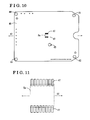
Fig. 10 is a plan view drawing illustrating an electronic circuit board for the displacement detection apparatus according to the embodiment; -
Fig. 11 is a plan view drawing illustrating the electronic circuit board for the displacement detection apparatus according to the embodiment in which a portion where lands are provided is enlarged; -
Fig. 12 is a plan view drawing illustrating the displacement detection apparatus according to the embodiment in which boding state of leads of a detection sensor and the lands of the electronic circuit board is enlarged; -
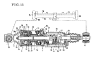
Fig. 13 is an axial direction cross-sectional view drawing illustrating a configuration of a rear wheel steering apparatus according to an embodiment disclosed here as a whole; -
Fig. 14 is an axial direction cross-sectional view drawing illustrating the rear wheel steering apparatus according to the embodiment in which an actuator portion is enlarged; -
Fig, 15 is an axial direction cross-sectional view drawing illustrating the rear wheel steering apparatus according to the embodiment in which a controller portion is enlarged; - A
displacement detection apparatus 5 for alinear motion mechanism 3c according to an embodiment disclosed here will be described referring toFigs. 1 through 12 . AsFig. 1 illustrates, thelinear motion mechanism 3c includes anut member 36 that makes rotational movement and arod 2 that screws through thenut member 36. Thelinear motion mechanism 3c converts rotational movement of thenut member 36 into linear movement of therod 2. Thelinear motion mechanism 3c may be referred to as a screw mechanism. Thedisplacement detection apparatus 5 according to the embodiment is for detecting displacement of therod 2 in the axial direction of therod 2. Thedisplacement detection apparatus 5 includes adisplacement sensor 5a and apermanent magnet 5b. Thepermanent magnet 5b is retained in amagnet block 50. Thelinear motion mechanism 3c is mounted on a rear wheel steering apparatus, which will be described later. Thenut member 36 is rotatably supported by abearing 37 and therod 2 is attached so as to penetrate through acase 12. An example of thedisplacement sensor 5a is a magnetic vector sensor. Thedisplacement sensor 5a is disposed at a position opposing to thepermanent magnet 5b as illustrated in two dot chain lines inFig. 1 . More specifically, thedisplacement sensor 5a is disposed on a central portion of anelectronic circuit board 40 within a region facing a path of movement of thepermanent magnet 5b so as to detect magnetic flux changes of thepermanent magnet 5b. - As
Figs. 1 and 2 illustrate,elongate grooves rod 2 so as to form opposing surfaces on therod 2. Theelongate grooves hole 2h extends between theelongate grooves magnet block 50 is positioned at one of theelongate grooves elongate groove 2r. Abolt 51 is inserted through the throughhole 2h from theelongate groove 2s on the opposite side and threadably mounted to anut 54 so as to retain themagnet block 50 on therod 2. Theelongate groove 2s is formed to have identical form as theelongate groove 2r in consideration of ease at the time of assembly, however, theelongate groove 2s may be formed in a form other than a rectangular recessed portion as long as theelongate groove 2s receives thebolt 51 therein. - The
magnet block 50, which is made of synthetic resin, is formed in an exterior form illustrated inFigs. 3 to 5 . AsFig. 6 illustrates, themagnet block 50 is formed so as to include a retainingportion 52 holding thepermanent magnet 5b and a pair ofleg portions 53 extending from ends of the retainingportion 52 spaced apart in the longitudinal direction of themagnet block 50. In a state where themagnet block 50 is retained on therod 2, the longitudinal direction corresponds to the axial direction of therod 2. In addition, thenut 54, which is made of metal, is Inserted-molded at an intermediate position between the pair ofleg portions 53 so as to form a part of themagnet block 50. A neodymium magnet is an example of thepermanent magnet 5b. Thepermanent magnet 5b includes protrusions 5be that are formed to extend in the axial direction from ends of thepermanent magnet 5b spaced apart in the axial direction. The retainingportion 52 and thepermanent magnet 5b including the protrusions 5be are integrally formed so that thepermanent magnet 5b is rigidly retained to the retainingportion 52. In addition, themagnet block 50 is formed with protrudingportions 55 on each of side surfaces of the retainingportion 52 at a portion where thenut 54 is insert-molded. - The
magnet block 50 is retained on therod 2, which is mounted in acase 12 of a rear wheel steering apparatus illustrated inFig. 9 , which will be described later. AsFigs. 1 and 2 illustrate, theleg portions 53 of themagnet block 50 and thenut 54 are fitted to theelongate groove 2r of therod 2, and thebolt 51 that is inserted through the throughhole 2h of therod 2 is threadably mounted to thenut 54. Accordingly, the rotational force that applies on thenut 54, the rotational force that results from the rotation of thebolt 51, is absorbed by theleg portions 53 being in contact with theinner side surface 2i of theelongate groove 2r. As a result, themagnet block 50 is reliably retained parallel to therod 2 without themagnet block 50 rotating with thenut 54 as the center of rotation. In other words, theleg portions 53 serve to define position of thepermanent magnet 5b relative to the rotational direction of thebolt 51. Accordingly, a single set of thebolt 51 and thenut 54 alone serves to fasten themagnet block 50 to therod 2. As a result, the component numbers are reduced compared to general methods of retaining a magnet block on a rod that use two or more sets of bolts and nuts. - As
Fig. 8 illustrates, asupport portion 12s is formed inside thecase 12. In addition, thecase 12 includes a pair of standingwall portions 12w extending parallel to the axis of therod 2 that is inserted through thecase 12. The protrudingportions 55 of themagnet block 50 are fitted between the standingwall portions 12w and thebolt 51, which is inserted through the throughhole 2h of therod 2, is threadably mounted to thenut 54. Accordingly, asFig. 9 illustrates, therod 2 is retained by themagnet block 50 in a state restrained from rotating relative to the standingwall portions 12w, in other words relative to thecase 12. The load that themagnet block 50 is required to withstand for restraining therod 2 from rotating relative to the standingwall portions 12w concentrates at the protrudingportions 55, which is at the portion of thenut 54 that is made of metal. Accordingly, the retainingportion 52 and thepermanent magnet 5b are prevented from receiving a large load, so that an accurate detection precision may be maintained. Other reference numerals inFig. 9 that are not mentioned in the above description are as same as the reference numerals for describing the components of the rear wheel steering apparatus that will be described later. The components provided with such reference numerals inFig. 9 will be described later in relation to a structure for supporting thedisplacement sensor 5a. - On the
electronic circuit board 40, plural elements are mounted and thedisplacement sensor 5a is disposed at the central portion of theelectronic circuit board 40. AsFig. 10 illustrates, screw holes 41, 42, 43, 44, 45 are formed to extend through theelectronic circuit board 40 and screws S are inserted into the screw holes 41, 42, 43 44, 45 asFig. 9 illustrates. Accordingly, theelectronic circuit board 40 is fixed to asupport base plate 46 at a position spaced by a predetermined distance relative to thesupport base plate 46. More specifically, thescrew hole 45 is provided at a position close to thedisplacement sensor 5a. Theelectronic circuit board 40 is screw-fixed to thesupport base plate 46 at the position of thescrew hole 45 in addition to the screw holes 41, 42, 43, 44 that are provided at four corners of theelectronic circuit board 40. As a result, thedisplacement sensor 5a is supported in a stable state. - As
Fig. 12 , which is an enlarged view drawing of theelectronic circuit board 40, illustrates, thedisplacement sensor 5a includes plural leads 5ax extending parallel to each other in a predetermined direction. Theelectronic circuit board 40 includesplural lands 47 extending parallel to each other in a predetermined direction corresponding to the leads 5ax. Likewise to generally known mounting methods, each of thelands 47 is provided with an area larger than each of the leads 5ax in order to compensate for errors at the time of bonding the leads 5ax and thelands 47. More specifically, the difference in sizes between the lead 5ax and theland 47 in a longitudinal direction, which is in y-direction inFig. 12 , is approximately four times of the difference in sizes between the lead 5ax and theland 47 in a width direction, which is in x-direction inFig. 12 . The allowed mounting error is proportional to the difference in sizes in each direction. In thedisplacement detection apparatus 5 for thelinear motion mechanism 3c according to the embodiment, theelectronic circuit board 40 is screw-fixed to thesupport base plate 46 in a state where the plural leads 5ax extending parallel to each other and theplural lands 47 extending parallel to each other extend in the direction perpendicular to the moving direction ST of thepermanent magnet 5b, which is the direction of the stroke of therod 2, in other words the y-direction inFig. 12 . As a result, the detection errors for the displacement of thepermanent magnet 5b and for the displacement of therod 2 are reduced to minimum so that an accurate detection precision may be maintained. Other reference numerals inFig. 1 andFig. 9 that are not mentioned in the above description are as same as the reference numerals for describing the components of the rear wheel steering apparatus, which will be described later. The components provided with such reference numerals inFigs. 1 and9 will be described later in this disclosure. - The rear wheel steering apparatus including the
displacement detection apparatus 5 arranged in the abovementioned configuration according to an embodiment will be described next referring toFigs. 13 through 15 . The rear wheel steering apparatus according to the embodiment is an apparatus composing a portion of a four wheel steering (4WS) system. The front wheel steering system is similar to a known system and description of which will be omitted. Various suspension mechanisms for supporting rear wheels of a vehicle are known. A suspension mechanism according to the embodiment is configured as illustrated inFig. 13 with two-dot chain lines. The suspension mechanism includes a rear axle RA supporting the rear wheels RL, RR of a vehicle, a retaining portion RS on the rear axle RA, and a link LS that is axially supported on the rear axle RA so as to rotate with a rotation center C as the center of rotation. An actuator unit AU, which is a component of the rear wheel steering apparatus according to the embodiment, is disposed between the retaining portion RS and the link LS. Accordingly, the portion between the retaining portion RS and the link LS is driven to expand and contract so as to steer the rear wheels RL, RR via tie rods TR in response to the rotating movement of the link LS. - In the actuator unit AU, the
rod 2 is supported by a housing 1 so as to be linearly movable in the axial direction. One end portion of the actuator unit AU is connected to the link LS via a ball joint JL. The housing 1 is connected to the retaining portion RS via a ball joint JA. Anactuator 3 drives therod 2 so as to drive a portion of the rear axle RA between the retaining portion RS and the link LS to expand and contract. More specifically, anelectric motor 3a, which is a component of theactuator 3, is controlled by a controller 4. After the speed of the rotational output from theelectric motor 3a is reduced by aspeed reducing mechanism 3b, the rotational output is converted into a linear movement of therod 2 via thelinear motion mechanism 3c. In the rear wheel steering apparatus according to the embodiment, theelectric motor 3a is a brushless motor. The ball joint JA serves as the first connecting member and the ball joint JL serves as the second connecting member. - In the rear wheel steering apparatus according to the embodiment, the housing 1 includes a
housing 1a mainly accommodating components of theactuator 3, for example, theelectric motor 3a, and ahousing 1b mainly accommodating components of the controller 4, for example, theelectronic circuit board 40. A connectingcover 11 is connected to atubular body 10, which is a component composing thehousing 1a. In addition, thecase 12, which is a component of thehousing 1b, having opening portions in the upward-downward directions and in the axial directions is connected to thetubular body 10. Acover body 15 and acover body 16 are connected to the opening portions in the upward-downward directions. In the rear wheel steering apparatus according to the embodiment, the housing 1 is made of metal. The connectingcover 11 and thecase 12 are made of aluminum. Thetubular body 10, thecover body 15, and thecover body 16 are made of iron. -
Fig. 14 illustrates enlarged view of the configuration of theactuator 3. Astator 24 is press fitted to thetubular body 10 and retained thereat in a state where acoil 23 is wound around thestator 24. Ahollow rotation shaft 20 serves as the output shaft of theelectric motor 3a. Thehollow rotation shaft 20 is rotatably supported to aninner diameter portion 25a of amotor cover 25, which is inserted into thetubular body 10, via abearing 25b. Theinner diameter portion 25a is formed in an annular form. In addition, thehollow rotation shaft 20 is rotatably supported to anannular groove 12a that is formed on thecase 12 via abearing 12b. A core 21, which is a component forming a rotor of theelectric motor 3a, is press fitted to thehollow rotation shaft 20 and retained at an intermediate portion of thehollow rotation shaft 20 in the axial direction.Permanent magnets 22 separated by equal distance are circumferentially disposed on thecore 21. - In addition, the
rod 2 is coaxially disposed in thehollow rotation shaft 20 and supported to thehollow rotation shaft 20 so as to be linearly movable in the axial direction relative to the housing 1 and so as to be restrained from rotating relative to the housing 1. Abush 2a and abush 2b are disposed between therod 2 and thesupport portion 12s for reducing sliding resistance so as to smoothly move therod 2 in the axial direction of therod 2. The rear wheel steering apparatus according to the embodiment is a cantilever expansion-contraction mechanism. Accordingly, thebush 2a and thebush 2b are not required to serve as bearings for an axial direction displacement mechanism having both end support structure. - In the rear wheel steering apparatus according to the embodiment, the
speed reducing mechanism 3b is formed by aplanetary gear mechanism 30. In thespeed reducing mechanism 3b, asun gear 31, which is an external gear, is integrally connected to thehollow rotation shaft 20 and rotatably supported together with thehollow rotation shaft 20. Aring gear 33, which is an internal gear, is fixed to aholder 34, which is a tubular retaining member. Planetary gears 32, each of which is an external gear, mesh with thesun gear 31 and thering gear 33. Theplanetary gears 32 are disposed so as to rotate around thesun gear 31. As a carrier for rotatably supporting theplanetary gears 32 viapins 35, thenut member 36 is rotatbly supported to theholder 34 via abearing 37. Thebearing 37 is a ball bearing. Aninner ring 37a of thebearing 37 fits to thenut member 36. In addition, theouter ring 37b of thebearing 37 fits to theholder 34. Thebearing 37 is retained on thenut member 36 with aspacer 37c formed in a C-form. - In the rear wheel steering apparatus according to the embodiment, the
holder 34 and thepin 35 are made of metal, for example, iron. Thesun gear 31, theplanetary gears 32 and thering gear 33 are made of synthetic resin. Thesun gear 31 is integrated with thehollow rotation shaft 20, which is made of metal. Thering gear 33 is supported by theholder 34 in a state where thering gear 33 is restrained from rotating relative to theholder 34. Theholder 34 is supported by thetubular body 10 in a state where theholder 34 is restrained from rotating relative to thetubular body 10. AsFig. 14 illustrates, asnap ring 14 is retained at anannular groove 10a formed in thetubular body 10. In a state where theouter ring 37b of thebearing 37 and theholder 34 are sandwiched between the annular side surface of thesnap ring 14 and the annular open end surface of the connectingcover 11, alock nut 13 formed in an annular form is threadably mounted to the threaded portion formed at an open end of thetubular body 10 positioned in the direction of thespeed reducing mechanism 3b, which is leftward inFig. 14 , so as to fasten thetubular body 10 and the connectingcover 11. By the pressing force directed in the axial direction, which is generated as a result of threadably mounting thelock nut 13, theouter ring 37b of thebearing 37 and theholder 34 are rigidly sandwiched between thesnap ring 14 and the connectingcover 11. As a result, theholder 34 is restrained from rotating relative to thetubular body 10. - In the rear wheel steering apparatus according to the embodiment, an
external thread portion 2c, which is formed with trapezoidal threads extending for a predetermined length in the axial direction on the external circumferential surface of one end of therod 2, and aninternal thread portion 36c, which is formed on the internal circumferential surface of thenut member 36, are disposed so as to screw together. Accordingly, thelinear motion mechanism 3c is configured with thenut member 36 and therod 2. In order to prevent therod 2 from falling off, anut 2d is screwed on an edge portion of theexternal thread portion 2c. The load in the axial direction that may be applied onrod 2, which is supported as described above, is absorbed by thetubular body 10 and the connectingcover 11 via thenut member 36, thebearing 37, theholder 34, and thesnap ring 14. -
Fig. 15 illustrates thehousing 1 b that houses a controller 4 including theelectronic circuit board 40, which is a component of an electronic control apparatus, and thedisplacement sensor 5a and themagnet block 50, which are components of thedisplacement detection apparatus 5. In thedisplacement detection apparatus 5 illustrated inFig. 15 , thedisplacement sensor 5a is retained on theelectronic circuit board 40. Note that, thedisplacement detection apparatus 5 inFig. 15 is illustrated in an upside down position compared to thedisplacement detection apparatus 5 illustrated inFig. 1 . Other components are similar to those illustrated inFigs. 1 through 12 and descriptions in detail of those will be omitted. Themagnet block 50 serves to detect displacement of therod 2 when therod 2 moves linearly. In addition, themagnet block 50 serves to restrain therod 2 from rotating. - In the rear wheel steering apparatus according to the embodiment, the
actuator 3 drives thehollow rotation shaft 20 with theelectric motor 3a, which in turn drives thenut member 36 to rotate after the rotational force of thehollow rotation shaft 20 is reduced in speed by thespeed reducing mechanism 3b of theplanetary gear mechanism 30, so thatlinear motion mechanism 3c converts the rotational motion of thenut member 36 to the linear motion of therod 2. As a result, as described earlier, the portion of the rear axle RA between the retaining portion RS and the link LS is driven to expand and contract so as to adjust the steering angle of the rear wheels RL, RR. - According to an aspect of this disclosure, a
displacement detection apparatus 5 for alinear motion mechanism 3c includes anut member 36, arod 2 that screws through thenut member 36, thelinear motion mechanism 3c converting rotational movement of thenut member 36 into linear movement of therod 2, anelectronic circuit board 40 configured to be mounted with plural elements, asupport base plate 46 supporting theelectronic circuit board 40 at a position spaced by a predetermined distance relative to thesupport base plate 46, apermanent magnet 5b disposed parallel to therod 2, and adisplacement sensor 5a disposed at a central portion of theelectronic circuit board 40 within a region facing a path of movement of thepermanent magnet 5b, thedisplacement sensor 5a detecting magnetic flux changes of thepermanent magnet 5b. Theelectronic circuit board 40 is fixed to thesupport base plate 46 at a position close to thedisplacement sensor 5a. - Accordingly, the
displacement sensor 5a is appropriately supported on theelectronic circuit board 40 so that thedisplacement detection apparatus 5 for thelinear motion mechanism 3c may be decreased in size, weight, and cost. - According to another aspect of this disclosure, the
displacement sensor 5a of thedisplacement detection apparatus 5 for thelinear motion mechanism 3c includes plural leads 5ax extending parallel to each other in a predetermined direction. In addition, theelectronic circuit board 40 includesplural lands 47 extending parallel to each other in a predetermined direction. The plural leads 5ax of thedisplacement sensor 5a are bonded to the plural lands 47. Theelectronic circuit board 40 is screw-fixed to thesupport base plate 46 in a state where the plural leads 5ax extend in the direction perpendicular to the moving direction ST of thepermanent magnet 5b. - Accordingly, the
displacement sensor 5a may be easily and appropriately attached to theelectronic circuit board 40 with a minimum detection error so that an accurate detection precision of thedisplacement sensor 5a may be maintained. - According to further aspect of this disclosure, a rear wheel steering apparatus for a vehicle includes a housing 1 that connects to a suspension mechanism for supporting rear wheels RL, RR of the vehicle via a first connecting member (a ball joint JA) and a second connecting member (a ball joint JL), an electric motor 3a housed in the tubular body 10 composing a portion of the housing 1, a speed reducing mechanism 3b housed in the tubular body 10 and reducing speed of an output from the electric motor 3a, a nut member 36 that connects to the speed reducing mechanism 3b and rotating, a rod 2 that screws through the nut member 36, the rod 2 that connects to the second connecting member (the ball joint JL), the linear motion mechanism 3c converting rotational movement of the nut member 36 into linear movement of the rod 2, a case 12 composing a portion of the housing 1, the case 12 disposed to surround the rod 2 and fixedly connecting to the tubular body 10, an electronic circuit board 40 disposed in the case 12, the electronic circuit board 40 configured to be mounted with plural elements, a support base plate 46 supporting the electronic circuit board 40 at a position spaced by a predetermined distance relative to the support base plate 46, a permanent magnet 5b disposed parallel to the rod 2, and a displacement sensor 5a disposed at a central portion of the electronic circuit board 40 within a region facing a path of movement of the permanent magnet 5b, the displacement sensor 5a detecting magnetic flux changes of the permanent magnet 5b. The
electronic circuit board 40 is fixed to thesupport base plate 46 at a position close to thedisplacement sensor 5a. - Accordingly, the
displacement sensor 5a is appropriately supported on theelectronic circuit board 40 so that thedisplacement detection apparatus 5 of thelinear motion mechanism 3c may be decreased in size, weight, and the rear wheel steering apparatus as a whole may be decreased in cost. - According to another aspect of this disclosure, the
displacement sensor 5a of the rear wheel steering apparatus for a vehicle includes plural leads 5ax extending parallel to each other in a predetermined direction. In addition, theelectronic circuit board 40 includesplural lands 47 extending parallel to each other in a predetermined direction. The plural leads 5ax of thedisplacement sensor 5a are bonded to the plural lands 47. Theelectronic circuit board 40 is screw-fixed to thesupport base plate 46 in a state where the plural leads 5ax extend in a direction perpendicular to a moving direction ST of thepermanent magnet 5b. - Accordingly, the
displacement sensor 5a may be easily and appropriately attached to theelectronic circuit board 40 with a minimum detection error so that an accurate detection precision of thedisplacement sensor 5a may be maintained. - A displacement detection apparatus (5) for a linear motion mechanism (3c) includes a nut member (36), a rod (2) including elongate grooves (2r, 2s) elongating in an axial direction of the rod (2) and a through hole (2h), a permanent magnet (5b) disposed parallel to the rod (2), a magnet block (50) made of synthetic resin and including a retaining portion (52) holding the permanent magnet (5b), a pair of leg portions (53) extending from ends of the retaining portion (52) that are spaced apart, and a nut (54) made of metal insert-molded at an intermediate position between the pair of leg portions (53), and a displacement sensor (5a) disposed opposing to the permanent magnet (5b). The pair of leg portions (53) and the nut (54) of the magnet block (50) are disposed in the elongate groove (2r) of the rod (2) and the magnet block (50) is fixed to the rod (2) by a bolt (51) screwed to the nut (54), the bolt (51) penetrating through the through hole (2h) extending through the rod (2).
Claims (5)
- A displacement detection apparatus (5) for a linear motion mechanism (3c), comprising:a nut member (36);a rod (2) that screws through the nut member (36), the rod (2) including elongate grooves (2r, 2s) elongating in an axial direction of the rod (2) and a through hole (2h) extending between the elongate grooves (2r, 2s);the linear motion mechanism (3c) converting rotational movement of the nut member (36) into linear movement of the rod (2);a permanent magnet (5b) disposed parallel to the rod (2);a magnet block (50) made of synthetic resin and including a retaining portion (52) holding the permanent magnet (5b), a pair of leg portions (53) extending from ends of the retaining portion (52) that are spaced apart, and a nut (54) made of metal that is insert-molded at an intermediate position between the pair of leg portions (53); anda displacement sensor (5a) disposed opposing to the permanent magnet (5b) and detecting displacement of the rod (2) in the axial direction, whereinthe pair of leg portions (53) and the nut (54) of the magnet block (50) are disposed in the elongate groove (2r) of the rod (2) and the magnet block (50) is fixed to the rod (2) by a bolt (51) screwed to the nut (54), the bolt (51) penetrating through the through hole (2h) extending through the rod (2).
- The displacement detection apparatus (5) for the linear motion mechanism (3c) according to Claim 1, further comprising:a case (12) including a pair of standing wall portions (12w) extending parallel to an axis of the rod (2), whereinthe retaining portion (52) of the magnet block (50) is disposed between the pair of standing wall portions (12w) to be retained thereat, and whereinthe rod (2) is supported by the magnet block (50) to be restrained from rotating relative to the case (12).
- The displacement detection apparatus (5) for the linear motion mechanism (3c) according to Claim 2, wherein
the magnet block (50) includes protruding portions (55) on side surfaces of the magnet block (50) at a portion where the nut (54) is insert-molded, wherein
the protruding portions (55) are fitted between the pair of standing wall portions (12w). - The displacement detection apparatus (5) for the linear motion mechanism (3c) according to Claim 1, wherein
the pair of leg portions (53) of the magnet block (50) are in contact with an inner side surface (2i) of the elongate groove (2r) provided on the rod (2). - A rear wheel steering apparatus for a vehicle including the displacement detection apparatus (5) for the linear motion mechanism (3c) according to Claim 1.
Applications Claiming Priority (2)
| Application Number | Priority Date | Filing Date | Title |
|---|---|---|---|
| JP2013112510A JP6349627B2 (en) | 2013-05-29 | 2013-05-29 | Displacement detection device for linear motion mechanism, and rear wheel steering device for vehicle equipped with the device |
| JP2013112515A JP6115320B2 (en) | 2013-05-29 | 2013-05-29 | Displacement detection device for linear motion mechanism, and rear wheel steering device for vehicle equipped with the device |
Publications (2)
| Publication Number | Publication Date |
|---|---|
| EP2816321A1 true EP2816321A1 (en) | 2014-12-24 |
| EP2816321B1 EP2816321B1 (en) | 2018-05-23 |
Family
ID=50841602
Family Applications (1)
| Application Number | Title | Priority Date | Filing Date |
|---|---|---|---|
| EP14170166.4A Active EP2816321B1 (en) | 2013-05-29 | 2014-05-28 | Displacement detection apparatus for linear motion mechanism and rear wheel steering apparatus for vehicle including the same |
Country Status (3)
| Country | Link |
|---|---|
| US (1) | US9254868B2 (en) |
| EP (1) | EP2816321B1 (en) |
| CN (1) | CN104210535B (en) |
Cited By (3)
| Publication number | Priority date | Publication date | Assignee | Title |
|---|---|---|---|---|
| WO2018077837A1 (en) * | 2016-10-27 | 2018-05-03 | Melecs Ews Gmbh | Sensor arrangement for a brake unit of a vehicle |
| EP3355031A1 (en) * | 2017-01-28 | 2018-08-01 | Aisin Seiki Kabushiki Kaisha | Displacement detection apparatus for linear motion mechanism and rear wheel steering apparatus for vehicle including the same |
| KR102008693B1 (en) * | 2018-02-22 | 2019-08-08 | 주식회사 만도 | Rotary sensor structure and Rear wheel steering device including the same |
Families Citing this family (20)
| Publication number | Priority date | Publication date | Assignee | Title |
|---|---|---|---|---|
| KR101957781B1 (en) * | 2014-06-11 | 2019-03-13 | 주식회사 만도 | Linear Sensor Apparatus for Vehicle |
| KR102160118B1 (en) * | 2014-06-18 | 2020-09-25 | 주식회사 만도 | Method of preventing over stroke in rear wheel steering system |
| US20160169310A1 (en) * | 2014-12-11 | 2016-06-16 | Goodrich Corporation | Contactless linear position sensor system |
| JP6647900B2 (en) | 2016-02-09 | 2020-02-14 | Ntn株式会社 | Electric actuator |
| JP6696811B2 (en) | 2016-03-30 | 2020-05-20 | Ntn株式会社 | Sensor target, movable unit including the target, and electric actuator |
| CN106627761B (en) * | 2016-12-23 | 2023-07-14 | 徐工消防安全装备有限公司 | Novel from walking operation platform off-vehicle steering detection device |
| CN107449356B (en) * | 2017-09-13 | 2023-12-08 | 无锡商业职业技术学院 | Hall effect steering wheel angle sensor based on single-stage planetary gear transmission |
| DE102017217631B3 (en) * | 2017-10-04 | 2018-07-26 | Zf Friedrichshafen Ag | Actuator of a steering and steer-by-wire steering of a motor vehicle |
| JP2019148299A (en) * | 2018-02-27 | 2019-09-05 | Ntn株式会社 | Screw shaft, feed screw mechanism and electric actuator |
| JP7145014B2 (en) | 2018-09-11 | 2022-09-30 | 日立Astemo株式会社 | steering device |
| DE102018130228B3 (en) * | 2018-11-29 | 2020-02-20 | Schaeffler Technologies AG & Co. KG | Actuator for rear axle steering of a vehicle and rear axle steering with such an actuator |
| DE102019209930B4 (en) * | 2019-07-05 | 2022-03-17 | Zf Friedrichshafen Ag | Actuator of a steer-by-wire steering with a spindle drive and steer-by-wire steering |
| KR102682960B1 (en) * | 2019-07-24 | 2024-07-05 | 에이치엘만도 주식회사 | Steer-by-wire type steering apparatus |
| DE102019125883A1 (en) * | 2019-09-26 | 2021-04-01 | Schaeffler Technologies AG & Co. KG | Linear actuator with measuring device for determining a position of a linearly movable component |
| JP2022154362A (en) * | 2021-03-30 | 2022-10-13 | 本田技研工業株式会社 | suspension device |
| KR20220155066A (en) * | 2021-05-14 | 2022-11-22 | 에이치엘만도 주식회사 | Steering Apparatus for Vehicle |
| CN113184051A (en) * | 2021-06-11 | 2021-07-30 | 浙江沃德尔科技集团股份有限公司 | Intelligent steering rear wheel steering position sensor |
| KR20230024009A (en) * | 2021-08-11 | 2023-02-20 | 현대모비스 주식회사 | Steering device for vehicle |
| KR20230063050A (en) * | 2021-11-01 | 2023-05-09 | 현대모비스 주식회사 | Steering device for vehicle |
| USD1078497S1 (en) * | 2022-02-08 | 2025-06-10 | Israel Michael Debro | Measuring device assembly |
Citations (5)
| Publication number | Priority date | Publication date | Assignee | Title |
|---|---|---|---|---|
| EP0376456A2 (en) * | 1988-12-28 | 1990-07-04 | Ford Motor Company Limited | Steering system position detector |
| US20010003435A1 (en) * | 1999-12-08 | 2001-06-14 | Alps Electric Co., Ltd. | Angle sensor which makes it possible to prevent rattling caused by backlash between gears inside the angle sensor |
| JP3601170B2 (en) | 1995-04-19 | 2004-12-15 | アイシン精機株式会社 | Vehicle steering control device |
| EP2130744A1 (en) * | 2007-03-16 | 2009-12-09 | Honda Motor Co., Ltd. | Actuator for vehicle |
| JP5098242B2 (en) | 2006-07-26 | 2012-12-12 | アイシン精機株式会社 | Wheel steering device |
Family Cites Families (19)
| Publication number | Priority date | Publication date | Assignee | Title |
|---|---|---|---|---|
| GB2194201B (en) * | 1986-08-22 | 1990-07-04 | Honda Motor Co Ltd | Steering angle detector |
| US5083626A (en) * | 1986-10-20 | 1992-01-28 | Honda Giken Kogyo Kabushiki Kaishi | Rear wheel steering device for vehicle with four steerable wheels |
| US5234068A (en) * | 1989-08-07 | 1993-08-10 | Honda Giken Kogyo Kabushiki Kaisha | Electric power steering system |
| DE19744722B4 (en) * | 1997-10-10 | 2010-01-07 | Robert Bosch Gmbh | Arrangement for detecting the steering angle in motor vehicles |
| EP1201529B1 (en) * | 2000-10-27 | 2008-04-09 | VDO Automotive AG | Motor vehicle steering angle determination method and apparatus |
| US7293626B2 (en) * | 2001-08-01 | 2007-11-13 | Delphi Technologies, Inc. | Apparatus and method for steering a vehicle |
| US6691819B2 (en) * | 2001-09-17 | 2004-02-17 | Delphi Technologies, Inc. | Actuator for active front wheel steering system |
| DE10329293A1 (en) * | 2003-06-30 | 2005-01-20 | Zf Lenksysteme Gmbh | Device for detecting a rotational movement in a vehicle steering device |
| KR100814053B1 (en) * | 2003-11-18 | 2008-03-14 | 가부시키가이샤 제이텍트 | Electric power steering device |
| JP4779495B2 (en) * | 2004-10-27 | 2011-09-28 | 日産自動車株式会社 | Vehicle steering system |
| DE602006015337D1 (en) * | 2005-10-28 | 2010-08-19 | Toyota Motor Co Ltd | POWER STEERING |
| JP5019104B2 (en) * | 2006-12-28 | 2012-09-05 | 株式会社ジェイテクト | Vehicle steering system |
| JP4605265B2 (en) * | 2008-07-22 | 2011-01-05 | トヨタ自動車株式会社 | Vehicle steering device |
| PL2383167T3 (en) * | 2010-04-27 | 2014-05-30 | Thyssenkrupp Presta Ag | Method for controlling a steering apparatus |
| WO2012022300A2 (en) * | 2010-08-14 | 2012-02-23 | Micro-Epsilon Messtechnik Gmbh & Co. Kg | Method and apparatus for sensing magnetic fields |
| FR2967255B1 (en) * | 2010-11-04 | 2019-03-22 | Continental Automotive France | DEVICE FOR DETERMINING THE POSITION OF A MAGNETIC ELEMENT USING LINEAR HALL EFFECT CELLS |
| JP5466185B2 (en) * | 2011-02-08 | 2014-04-09 | トヨタ自動車株式会社 | Vehicle rear wheel steering device |
| DE102012210225A1 (en) * | 2012-06-18 | 2013-12-19 | Zf Friedrichshafen Ag | Adjustment device for a chassis of a vehicle with sliding block |
| CN104210544B (en) * | 2013-05-29 | 2018-01-23 | 爱信精机株式会社 | The apparatus for rear wheel steering of vehicle |
-
2014
- 2014-05-28 EP EP14170166.4A patent/EP2816321B1/en active Active
- 2014-05-28 CN CN201410230984.2A patent/CN104210535B/en active Active
- 2014-05-29 US US14/289,827 patent/US9254868B2/en active Active
Patent Citations (5)
| Publication number | Priority date | Publication date | Assignee | Title |
|---|---|---|---|---|
| EP0376456A2 (en) * | 1988-12-28 | 1990-07-04 | Ford Motor Company Limited | Steering system position detector |
| JP3601170B2 (en) | 1995-04-19 | 2004-12-15 | アイシン精機株式会社 | Vehicle steering control device |
| US20010003435A1 (en) * | 1999-12-08 | 2001-06-14 | Alps Electric Co., Ltd. | Angle sensor which makes it possible to prevent rattling caused by backlash between gears inside the angle sensor |
| JP5098242B2 (en) | 2006-07-26 | 2012-12-12 | アイシン精機株式会社 | Wheel steering device |
| EP2130744A1 (en) * | 2007-03-16 | 2009-12-09 | Honda Motor Co., Ltd. | Actuator for vehicle |
Cited By (4)
| Publication number | Priority date | Publication date | Assignee | Title |
|---|---|---|---|---|
| WO2018077837A1 (en) * | 2016-10-27 | 2018-05-03 | Melecs Ews Gmbh | Sensor arrangement for a brake unit of a vehicle |
| EP3355031A1 (en) * | 2017-01-28 | 2018-08-01 | Aisin Seiki Kabushiki Kaisha | Displacement detection apparatus for linear motion mechanism and rear wheel steering apparatus for vehicle including the same |
| KR102008693B1 (en) * | 2018-02-22 | 2019-08-08 | 주식회사 만도 | Rotary sensor structure and Rear wheel steering device including the same |
| US11427250B2 (en) | 2018-02-22 | 2022-08-30 | Mando Corporation | Rotary sensor assembly and rear wheel steering system including the same |
Also Published As
| Publication number | Publication date |
|---|---|
| US9254868B2 (en) | 2016-02-09 |
| CN104210535A (en) | 2014-12-17 |
| EP2816321B1 (en) | 2018-05-23 |
| US20140353071A1 (en) | 2014-12-04 |
| CN104210535B (en) | 2017-10-24 |
Similar Documents
| Publication | Publication Date | Title |
|---|---|---|
| EP2816321B1 (en) | Displacement detection apparatus for linear motion mechanism and rear wheel steering apparatus for vehicle including the same | |
| JP6349627B2 (en) | Displacement detection device for linear motion mechanism, and rear wheel steering device for vehicle equipped with the device | |
| JP6514135B2 (en) | Electric drive device and electric power steering device | |
| EP2808231A1 (en) | Rear wheel steering apparatus for vehicle | |
| JP6522536B2 (en) | Electric drive device and electric power steering device | |
| JP6505038B2 (en) | Electric drive device and electric power steering device | |
| JP6514136B2 (en) | Electric drive device and electric power steering device | |
| EP2676866A1 (en) | Vehicle steering device and vehicle steering device manufacturing method | |
| JP6115320B2 (en) | Displacement detection device for linear motion mechanism, and rear wheel steering device for vehicle equipped with the device | |
| EP2808229B1 (en) | Rear wheel steering apparatus for vehicle | |
| EP3355031A1 (en) | Displacement detection apparatus for linear motion mechanism and rear wheel steering apparatus for vehicle including the same | |
| JP2008284912A (en) | Vehicle steering system | |
| EP2998202B1 (en) | Rear wheel steering apparatus for vehicle | |
| WO2016129436A1 (en) | Rear wheel steering device | |
| EP2709241A2 (en) | Rotor of electric motor and rear wheel steering apparatus for vehicle including rotor | |
| JP6248418B2 (en) | Vehicle rear wheel steering device | |
| US20170029012A1 (en) | Rear wheel steering device | |
| JP2017001408A (en) | Electric power steering device | |
| JP6210365B2 (en) | Rotor for electric motor, and rear wheel steering device for vehicle including the rotor | |
| JP6107427B2 (en) | Vehicle rear wheel steering device | |
| JP2014231277A (en) | Rear wheel steering device of vehicle | |
| JP6120163B2 (en) | Electronic control unit and vehicle rear wheel steering apparatus including the electronic control unit | |
| JP6107428B2 (en) | Vehicle rear wheel steering device | |
| JP6212961B2 (en) | Vehicle rear wheel steering device | |
| KR20220138569A (en) | Motor |
Legal Events
| Date | Code | Title | Description |
|---|---|---|---|
| PUAI | Public reference made under article 153(3) epc to a published international application that has entered the european phase |
Free format text: ORIGINAL CODE: 0009012 |
|
| 17P | Request for examination filed |
Effective date: 20140528 |
|
| AK | Designated contracting states |
Kind code of ref document: A1 Designated state(s): AL AT BE BG CH CY CZ DE DK EE ES FI FR GB GR HR HU IE IS IT LI LT LU LV MC MK MT NL NO PL PT RO RS SE SI SK SM TR |
|
| AX | Request for extension of the european patent |
Extension state: BA ME |
|
| RIN1 | Information on inventor provided before grant (corrected) |
Inventor name: YOSHIZAWA, NAOYA Inventor name: FUJII, SHIMPEI Inventor name: AKAGI, YUSUKE Inventor name: ANDO, SHINSUKE |
|
| R17P | Request for examination filed (corrected) |
Effective date: 20150428 |
|
| RBV | Designated contracting states (corrected) |
Designated state(s): AL AT BE BG CH CY CZ DE DK EE ES FI FR GB GR HR HU IE IS IT LI LT LU LV MC MK MT NL NO PL PT RO RS SE SI SK SM TR |
|
| GRAP | Despatch of communication of intention to grant a patent |
Free format text: ORIGINAL CODE: EPIDOSNIGR1 |
|
| RIC1 | Information provided on ipc code assigned before grant |
Ipc: G01D 5/14 20060101AFI20171110BHEP Ipc: B60G 17/019 20060101ALI20171110BHEP Ipc: B62D 7/14 20060101ALI20171110BHEP Ipc: B62D 15/02 20060101ALI20171110BHEP |
|
| INTG | Intention to grant announced |
Effective date: 20171205 |
|
| GRAS | Grant fee paid |
Free format text: ORIGINAL CODE: EPIDOSNIGR3 |
|
| GRAA | (expected) grant |
Free format text: ORIGINAL CODE: 0009210 |
|
| AK | Designated contracting states |
Kind code of ref document: B1 Designated state(s): AL AT BE BG CH CY CZ DE DK EE ES FI FR GB GR HR HU IE IS IT LI LT LU LV MC MK MT NL NO PL PT RO RS SE SI SK SM TR |
|
| REG | Reference to a national code |
Ref country code: GB Ref legal event code: FG4D |
|
| REG | Reference to a national code |
Ref country code: CH Ref legal event code: EP |
|
| REG | Reference to a national code |
Ref country code: IE Ref legal event code: FG4D |
|
| REG | Reference to a national code |
Ref country code: AT Ref legal event code: REF Ref document number: 1001879 Country of ref document: AT Kind code of ref document: T Effective date: 20180615 |
|
| REG | Reference to a national code |
Ref country code: DE Ref legal event code: R096 Ref document number: 602014025769 Country of ref document: DE |
|
| REG | Reference to a national code |
Ref country code: FR Ref legal event code: PLFP Year of fee payment: 5 |
|
| REG | Reference to a national code |
Ref country code: NL Ref legal event code: MP Effective date: 20180523 |
|
| REG | Reference to a national code |
Ref country code: LT Ref legal event code: MG4D |
|
| PG25 | Lapsed in a contracting state [announced via postgrant information from national office to epo] |
Ref country code: SE Free format text: LAPSE BECAUSE OF FAILURE TO SUBMIT A TRANSLATION OF THE DESCRIPTION OR TO PAY THE FEE WITHIN THE PRESCRIBED TIME-LIMIT Effective date: 20180523 Ref country code: ES Free format text: LAPSE BECAUSE OF FAILURE TO SUBMIT A TRANSLATION OF THE DESCRIPTION OR TO PAY THE FEE WITHIN THE PRESCRIBED TIME-LIMIT Effective date: 20180523 Ref country code: LT Free format text: LAPSE BECAUSE OF FAILURE TO SUBMIT A TRANSLATION OF THE DESCRIPTION OR TO PAY THE FEE WITHIN THE PRESCRIBED TIME-LIMIT Effective date: 20180523 Ref country code: FI Free format text: LAPSE BECAUSE OF FAILURE TO SUBMIT A TRANSLATION OF THE DESCRIPTION OR TO PAY THE FEE WITHIN THE PRESCRIBED TIME-LIMIT Effective date: 20180523 Ref country code: BG Free format text: LAPSE BECAUSE OF FAILURE TO SUBMIT A TRANSLATION OF THE DESCRIPTION OR TO PAY THE FEE WITHIN THE PRESCRIBED TIME-LIMIT Effective date: 20180823 Ref country code: NO Free format text: LAPSE BECAUSE OF FAILURE TO SUBMIT A TRANSLATION OF THE DESCRIPTION OR TO PAY THE FEE WITHIN THE PRESCRIBED TIME-LIMIT Effective date: 20180823 |
|
| PG25 | Lapsed in a contracting state [announced via postgrant information from national office to epo] |
Ref country code: RS Free format text: LAPSE BECAUSE OF FAILURE TO SUBMIT A TRANSLATION OF THE DESCRIPTION OR TO PAY THE FEE WITHIN THE PRESCRIBED TIME-LIMIT Effective date: 20180523 Ref country code: HR Free format text: LAPSE BECAUSE OF FAILURE TO SUBMIT A TRANSLATION OF THE DESCRIPTION OR TO PAY THE FEE WITHIN THE PRESCRIBED TIME-LIMIT Effective date: 20180523 Ref country code: GR Free format text: LAPSE BECAUSE OF FAILURE TO SUBMIT A TRANSLATION OF THE DESCRIPTION OR TO PAY THE FEE WITHIN THE PRESCRIBED TIME-LIMIT Effective date: 20180824 Ref country code: LV Free format text: LAPSE BECAUSE OF FAILURE TO SUBMIT A TRANSLATION OF THE DESCRIPTION OR TO PAY THE FEE WITHIN THE PRESCRIBED TIME-LIMIT Effective date: 20180523 Ref country code: NL Free format text: LAPSE BECAUSE OF FAILURE TO SUBMIT A TRANSLATION OF THE DESCRIPTION OR TO PAY THE FEE WITHIN THE PRESCRIBED TIME-LIMIT Effective date: 20180523 |
|
| REG | Reference to a national code |
Ref country code: CH Ref legal event code: PL |
|
| REG | Reference to a national code |
Ref country code: AT Ref legal event code: MK05 Ref document number: 1001879 Country of ref document: AT Kind code of ref document: T Effective date: 20180523 |
|
| REG | Reference to a national code |
Ref country code: BE Ref legal event code: MM Effective date: 20180531 |
|
| PG25 | Lapsed in a contracting state [announced via postgrant information from national office to epo] |
Ref country code: DK Free format text: LAPSE BECAUSE OF FAILURE TO SUBMIT A TRANSLATION OF THE DESCRIPTION OR TO PAY THE FEE WITHIN THE PRESCRIBED TIME-LIMIT Effective date: 20180523 Ref country code: PL Free format text: LAPSE BECAUSE OF FAILURE TO SUBMIT A TRANSLATION OF THE DESCRIPTION OR TO PAY THE FEE WITHIN THE PRESCRIBED TIME-LIMIT Effective date: 20180523 Ref country code: SK Free format text: LAPSE BECAUSE OF FAILURE TO SUBMIT A TRANSLATION OF THE DESCRIPTION OR TO PAY THE FEE WITHIN THE PRESCRIBED TIME-LIMIT Effective date: 20180523 Ref country code: CZ Free format text: LAPSE BECAUSE OF FAILURE TO SUBMIT A TRANSLATION OF THE DESCRIPTION OR TO PAY THE FEE WITHIN THE PRESCRIBED TIME-LIMIT Effective date: 20180523 Ref country code: AT Free format text: LAPSE BECAUSE OF FAILURE TO SUBMIT A TRANSLATION OF THE DESCRIPTION OR TO PAY THE FEE WITHIN THE PRESCRIBED TIME-LIMIT Effective date: 20180523 Ref country code: EE Free format text: LAPSE BECAUSE OF FAILURE TO SUBMIT A TRANSLATION OF THE DESCRIPTION OR TO PAY THE FEE WITHIN THE PRESCRIBED TIME-LIMIT Effective date: 20180523 Ref country code: RO Free format text: LAPSE BECAUSE OF FAILURE TO SUBMIT A TRANSLATION OF THE DESCRIPTION OR TO PAY THE FEE WITHIN THE PRESCRIBED TIME-LIMIT Effective date: 20180523 |
|
| REG | Reference to a national code |
Ref country code: IE Ref legal event code: MM4A |
|
| REG | Reference to a national code |
Ref country code: DE Ref legal event code: R097 Ref document number: 602014025769 Country of ref document: DE |
|
| PG25 | Lapsed in a contracting state [announced via postgrant information from national office to epo] |
Ref country code: CH Free format text: LAPSE BECAUSE OF NON-PAYMENT OF DUE FEES Effective date: 20180531 Ref country code: LI Free format text: LAPSE BECAUSE OF NON-PAYMENT OF DUE FEES Effective date: 20180531 Ref country code: SM Free format text: LAPSE BECAUSE OF FAILURE TO SUBMIT A TRANSLATION OF THE DESCRIPTION OR TO PAY THE FEE WITHIN THE PRESCRIBED TIME-LIMIT Effective date: 20180523 Ref country code: IT Free format text: LAPSE BECAUSE OF FAILURE TO SUBMIT A TRANSLATION OF THE DESCRIPTION OR TO PAY THE FEE WITHIN THE PRESCRIBED TIME-LIMIT Effective date: 20180523 |
|
| PG25 | Lapsed in a contracting state [announced via postgrant information from national office to epo] |
Ref country code: MC Free format text: LAPSE BECAUSE OF FAILURE TO SUBMIT A TRANSLATION OF THE DESCRIPTION OR TO PAY THE FEE WITHIN THE PRESCRIBED TIME-LIMIT Effective date: 20180523 Ref country code: LU Free format text: LAPSE BECAUSE OF NON-PAYMENT OF DUE FEES Effective date: 20180528 |
|
| PLBE | No opposition filed within time limit |
Free format text: ORIGINAL CODE: 0009261 |
|
| STAA | Information on the status of an ep patent application or granted ep patent |
Free format text: STATUS: NO OPPOSITION FILED WITHIN TIME LIMIT |
|
| GBPC | Gb: european patent ceased through non-payment of renewal fee |
Effective date: 20180823 |
|
| PG25 | Lapsed in a contracting state [announced via postgrant information from national office to epo] |
Ref country code: IE Free format text: LAPSE BECAUSE OF NON-PAYMENT OF DUE FEES Effective date: 20180528 |
|
| 26N | No opposition filed |
Effective date: 20190226 |
|
| PG25 | Lapsed in a contracting state [announced via postgrant information from national office to epo] |
Ref country code: SI Free format text: LAPSE BECAUSE OF FAILURE TO SUBMIT A TRANSLATION OF THE DESCRIPTION OR TO PAY THE FEE WITHIN THE PRESCRIBED TIME-LIMIT Effective date: 20180523 Ref country code: BE Free format text: LAPSE BECAUSE OF NON-PAYMENT OF DUE FEES Effective date: 20180531 |
|
| PG25 | Lapsed in a contracting state [announced via postgrant information from national office to epo] |
Ref country code: GB Free format text: LAPSE BECAUSE OF NON-PAYMENT OF DUE FEES Effective date: 20180823 |
|
| PG25 | Lapsed in a contracting state [announced via postgrant information from national office to epo] |
Ref country code: AL Free format text: LAPSE BECAUSE OF FAILURE TO SUBMIT A TRANSLATION OF THE DESCRIPTION OR TO PAY THE FEE WITHIN THE PRESCRIBED TIME-LIMIT Effective date: 20180523 |
|
| PG25 | Lapsed in a contracting state [announced via postgrant information from national office to epo] |
Ref country code: MT Free format text: LAPSE BECAUSE OF NON-PAYMENT OF DUE FEES Effective date: 20180528 |
|
| PG25 | Lapsed in a contracting state [announced via postgrant information from national office to epo] |
Ref country code: TR Free format text: LAPSE BECAUSE OF FAILURE TO SUBMIT A TRANSLATION OF THE DESCRIPTION OR TO PAY THE FEE WITHIN THE PRESCRIBED TIME-LIMIT Effective date: 20180523 |
|
| PG25 | Lapsed in a contracting state [announced via postgrant information from national office to epo] |
Ref country code: PT Free format text: LAPSE BECAUSE OF FAILURE TO SUBMIT A TRANSLATION OF THE DESCRIPTION OR TO PAY THE FEE WITHIN THE PRESCRIBED TIME-LIMIT Effective date: 20180523 Ref country code: HU Free format text: LAPSE BECAUSE OF FAILURE TO SUBMIT A TRANSLATION OF THE DESCRIPTION OR TO PAY THE FEE WITHIN THE PRESCRIBED TIME-LIMIT; INVALID AB INITIO Effective date: 20140528 |
|
| PG25 | Lapsed in a contracting state [announced via postgrant information from national office to epo] |
Ref country code: CY Free format text: LAPSE BECAUSE OF FAILURE TO SUBMIT A TRANSLATION OF THE DESCRIPTION OR TO PAY THE FEE WITHIN THE PRESCRIBED TIME-LIMIT Effective date: 20180523 Ref country code: MK Free format text: LAPSE BECAUSE OF NON-PAYMENT OF DUE FEES Effective date: 20180523 |
|
| PG25 | Lapsed in a contracting state [announced via postgrant information from national office to epo] |
Ref country code: IS Free format text: LAPSE BECAUSE OF FAILURE TO SUBMIT A TRANSLATION OF THE DESCRIPTION OR TO PAY THE FEE WITHIN THE PRESCRIBED TIME-LIMIT Effective date: 20180923 |
|
| REG | Reference to a national code |
Ref country code: FR Ref legal event code: PLFP Year of fee payment: 10 |
|
| PGFP | Annual fee paid to national office [announced via postgrant information from national office to epo] |
Ref country code: DE Payment date: 20250402 Year of fee payment: 12 |
|
| PGFP | Annual fee paid to national office [announced via postgrant information from national office to epo] |
Ref country code: FR Payment date: 20250401 Year of fee payment: 12 |