EP2816159A1 - Dual-arm work machine - Google Patents
Dual-arm work machine Download PDFInfo
- Publication number
- EP2816159A1 EP2816159A1 EP13749773.1A EP13749773A EP2816159A1 EP 2816159 A1 EP2816159 A1 EP 2816159A1 EP 13749773 A EP13749773 A EP 13749773A EP 2816159 A1 EP2816159 A1 EP 2816159A1
- Authority
- EP
- European Patent Office
- Prior art keywords
- operating
- working machine
- front working
- attachment
- drive command
- Prior art date
- Legal status (The legal status is an assumption and is not a legal conclusion. Google has not performed a legal analysis and makes no representation as to the accuracy of the status listed.)
- Granted
Links
Images








Classifications
-
- E—FIXED CONSTRUCTIONS
- E02—HYDRAULIC ENGINEERING; FOUNDATIONS; SOIL SHIFTING
- E02F—DREDGING; SOIL-SHIFTING
- E02F3/00—Dredgers; Soil-shifting machines
- E02F3/04—Dredgers; Soil-shifting machines mechanically-driven
- E02F3/96—Dredgers; Soil-shifting machines mechanically-driven with arrangements for alternate or simultaneous use of different digging elements
- E02F3/963—Arrangements on backhoes for alternate use of different tools
- E02F3/964—Arrangements on backhoes for alternate use of different tools of several tools mounted on one machine
-
- B—PERFORMING OPERATIONS; TRANSPORTING
- B25—HAND TOOLS; PORTABLE POWER-DRIVEN TOOLS; MANIPULATORS
- B25J—MANIPULATORS; CHAMBERS PROVIDED WITH MANIPULATION DEVICES
- B25J9/00—Program-controlled manipulators
- B25J9/16—Program controls
- B25J9/1679—Program controls characterised by the tasks executed
- B25J9/1682—Dual arm manipulator; Coordination of several manipulators
-
- E—FIXED CONSTRUCTIONS
- E02—HYDRAULIC ENGINEERING; FOUNDATIONS; SOIL SHIFTING
- E02F—DREDGING; SOIL-SHIFTING
- E02F3/00—Dredgers; Soil-shifting machines
- E02F3/04—Dredgers; Soil-shifting machines mechanically-driven
- E02F3/96—Dredgers; Soil-shifting machines mechanically-driven with arrangements for alternate or simultaneous use of different digging elements
-
- E—FIXED CONSTRUCTIONS
- E02—HYDRAULIC ENGINEERING; FOUNDATIONS; SOIL SHIFTING
- E02F—DREDGING; SOIL-SHIFTING
- E02F3/00—Dredgers; Soil-shifting machines
- E02F3/04—Dredgers; Soil-shifting machines mechanically-driven
- E02F3/96—Dredgers; Soil-shifting machines mechanically-driven with arrangements for alternate or simultaneous use of different digging elements
- E02F3/961—Dredgers; Soil-shifting machines mechanically-driven with arrangements for alternate or simultaneous use of different digging elements with several digging elements or tools mounted on one machine
-
- E—FIXED CONSTRUCTIONS
- E02—HYDRAULIC ENGINEERING; FOUNDATIONS; SOIL SHIFTING
- E02F—DREDGING; SOIL-SHIFTING
- E02F3/00—Dredgers; Soil-shifting machines
- E02F3/04—Dredgers; Soil-shifting machines mechanically-driven
- E02F3/96—Dredgers; Soil-shifting machines mechanically-driven with arrangements for alternate or simultaneous use of different digging elements
- E02F3/965—Dredgers; Soil-shifting machines mechanically-driven with arrangements for alternate or simultaneous use of different digging elements of metal-cutting or concrete-crushing implements
-
- E—FIXED CONSTRUCTIONS
- E02—HYDRAULIC ENGINEERING; FOUNDATIONS; SOIL SHIFTING
- E02F—DREDGING; SOIL-SHIFTING
- E02F9/00—Component parts of dredgers or soil-shifting machines, not restricted to one of the kinds covered by groups E02F3/00 - E02F7/00
- E02F9/20—Drives; Control devices
- E02F9/2004—Control mechanisms, e.g. control levers
- E02F9/2012—Setting the functions of the control levers, e.g. changing assigned functions among operations levers, setting functions dependent on the operator or seat orientation
-
- E—FIXED CONSTRUCTIONS
- E02—HYDRAULIC ENGINEERING; FOUNDATIONS; SOIL SHIFTING
- E02F—DREDGING; SOIL-SHIFTING
- E02F9/00—Component parts of dredgers or soil-shifting machines, not restricted to one of the kinds covered by groups E02F3/00 - E02F7/00
- E02F9/20—Drives; Control devices
- E02F9/22—Hydraulic or pneumatic drives
- E02F9/2221—Control of flow rate; Load sensing arrangements
- E02F9/2225—Control of flow rate; Load sensing arrangements using pressure-compensating valves
- E02F9/2228—Control of flow rate; Load sensing arrangements using pressure-compensating valves including an electronic controller
-
- E—FIXED CONSTRUCTIONS
- E02—HYDRAULIC ENGINEERING; FOUNDATIONS; SOIL SHIFTING
- E02F—DREDGING; SOIL-SHIFTING
- E02F9/00—Component parts of dredgers or soil-shifting machines, not restricted to one of the kinds covered by groups E02F3/00 - E02F7/00
- E02F9/20—Drives; Control devices
- E02F9/22—Hydraulic or pneumatic drives
- E02F9/2278—Hydraulic circuits
- E02F9/2285—Pilot-operated systems
-
- E—FIXED CONSTRUCTIONS
- E02—HYDRAULIC ENGINEERING; FOUNDATIONS; SOIL SHIFTING
- E02F—DREDGING; SOIL-SHIFTING
- E02F9/00—Component parts of dredgers or soil-shifting machines, not restricted to one of the kinds covered by groups E02F3/00 - E02F7/00
- E02F9/20—Drives; Control devices
- E02F9/22—Hydraulic or pneumatic drives
- E02F9/2278—Hydraulic circuits
- E02F9/2292—Systems with two or more pumps
-
- E—FIXED CONSTRUCTIONS
- E02—HYDRAULIC ENGINEERING; FOUNDATIONS; SOIL SHIFTING
- E02F—DREDGING; SOIL-SHIFTING
- E02F9/00—Component parts of dredgers or soil-shifting machines, not restricted to one of the kinds covered by groups E02F3/00 - E02F7/00
- E02F9/20—Drives; Control devices
- E02F9/22—Hydraulic or pneumatic drives
- E02F9/2278—Hydraulic circuits
- E02F9/2296—Systems with a variable displacement pump
Definitions
- the present invention relates to a dual-arm work machine that is equipped with working arms respectively on the right side and on the left side of the main body of the work machine.
- a dual-arm work machine that is equipped with working arms respectively on the right side and on the left side of the main body of the work machine is per se known.
- Operating levers respectively corresponding to the right and left working arms are provided to such a dual-arm working machine. Since actuators that are respectively provided to the right and left working arms are driven by operating these levers, accordingly it is possible to operate the right and left working arms independently (refer to Patent Document #1).
- a control technique for synchronizing the operation of two manipulators is per se known.
- the operator using an operating lever, the operator only performs driving operation of the manipulator on one side (the "master” side), and the operation of the two manipulators is synchronized by control being automatically performed so that the other manipulator (on the "slave” side) automatically tracks this master side manipulator.
- the slave side is feedback controlled by referring to the joint coordinates on the master side, and by taking them as target values (refer to Patent Document #2).
- a dual-arm work machine comprises: a first front working machine to which a first attachment is mounted; a second working machine to which a second attachment is mounted; a first drive device that drives the first front working machine and the first attachment based on a first drive command from a first operation member; a second drive device that drives the second front working machine and the second attachment based on a second drive command from a second operation member; and a drive command output device that inputs the first and second drive commands, and generates and outputs a shared drive command that drives the first and second drive devices.
- the dual-arm work machine further comprises an operation selection unit that can select either the first operation member or the second operation member; and the drive command output device generates and outputs a shared drive command to drive the first and second drive devices, based on the first drive command from the first operation member or the second drive command from the second operation member selected by the operation selection unit.
- the dual-arm work machine further comprises a first operating direction determination section that determines an operating direction of the first operation member, a second operating direction determination section that determines an operating direction of the second operation member, and a synchronized operation decision section that makes a decision as to whether or not the operating direction of the first operation member determined by the first operating direction determination section and the operating direction of the second operation member determined by the second operating direction determination section are the same; and if it is decided by the synchronized operation decision section that the operating direction of the first operation member and the operating direction of the second operation member are the same, the drive command output device generates and outputs the shared drive command based on the first drive command from the first operation member or the second drive command from the second operation member.
- the dual-arm work machine further comprises a first operating direction determination section that determines an operating direction of the first operation member, a second operating direction determination section that determines an operating direction of the second operation member, a first operating amount determination section that determines an operating amount of the first operation member, a second operating amount determination section that determines an operating amount of the second operation member, and a synchronized operation decision section that makes a decision as to whether or not the operating direction of the first operation member determined by the first operating direction determination section and the operating direction of the second operation member determined by the second operating direction determination section are the same; and if it is decided by the synchronized operation decision section that the operating direction of the first operation member and the operating direction of the second operation member are the same, the drive command output device generates and outputs the shared drive command based on an average value of the operating amount of the first operation member determined by the first operating amount determination section and an operating amount of the second operation member as determined
- the dual-arm work machine further comprises a first operating vector calculation unit that calculates an operating vector of the first operation member, a second operating vector calculation unit that calculates an operating vector of the second operation member, and a synchronized operation decision section that makes a decision as to whether or not the operating vector of the first operation member calculated by the first operating vector calculation unit and the operating vector of the second operation member calculated by the second operating vector calculation unit are approximately the same; and if it is decided by the synchronized operation decision section that the operating vector of the first operation member and the operating vector of the second operation member are approximately the same, the drive command output device generates and outputs the shared drive command based on the first drive command from the first operation member and/or the second drive command from the second operation member.
- the dual-arm work machine further comprises: a synchronization selection member that is operated in order for a user to select whether or not a movement of the first front working machine and the first attachment and a movement of the second front working machine and the second attachment are to be synchronized or not; and a shared drive command generation permission section that permits generation and output of the shared drive command by the drive command output device if synchronization of the movement of the first front working machine and the first attachment and the movement of the second front working machine and the second attachment is selected by the synchronization selection member, and prohibits generation and output of the shared drive command by the drive command output device if synchronization of the movement of the first front working machine and the first attachment and the movement of the second front working machine and the second attachment is not selected by the synchronization selection member.
- the dual-arm work machine further comprises: a first attitude detection unit that detects an attitude of the first front working machine and the first attachment; a second attitude detection unit that detects an attitude of the second front working machine and the second attachment; an attitude determination section that determines whether or not the attitude of the first front working machine and the first attachment detected by the first attitude detection unit and the attitude of the second front working machine and the second attachment detected by the second attitude detection unit are approximately the same; and a shared drive command generation permission section that permits generation and output of the shared drive command by the drive command output device when it is decided by the attitude determination section that the attitude of the first front working machine and the first attachment and the attitude of the second front working machine and the second attachment are approximately the same, and prohibits generation and output of the shared drive command by the drive command output device when it is decided by the attitude determination section that the attitude of the first front working machine and the first attachment and the attitude of the second front working machine and the second front are approximately the same, and prohibits generation and output of the shared drive command by the drive command output device when it is decided by the attitude determination
- the dual-arm work machine further comprises a synchronization selection member that is operated in order for the user to select whether or not the movement of the first front working machine and the first attachment and the movement of the second front working machine and the second attachment are to be synchronized or not; and the shared drive command generation permission section permits generation and output of the shared drive command by the drive command output device when it is decided by the attitude determination section that the attitude of the first front working machine and the first attachment and the attitude of the second front working machine and the second attachment are approximately the same, and synchronization of the movement of the first front working machine and the first attachment and the movement of the second front working machine and the second attachment is selected by the synchronization selection member, and prohibits generation and output of the shared drive command by the drive command output device when it is decided by the attitude determination section that the attitude of the first front working machine and the first attachment and the attitude of the second front working machine and the second attachment are not approximately the same, or
- a convenient structure can be implemented for synchronizing the operation of the first front working machine and the first attachment, with the operation of the second front working machine and the second attachment, and accordingly it is possible to provide at low cost a dual-arm work machine that can be applied to a wide range of tasks.
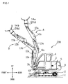
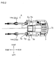
- Figs. 1 and 2 are figures showing the dual-arm work machine according to the first embodiment.
- the work machine 200 of the first embodiment is a work machine that is constructed on the basis of a hydraulic excavator.
- a revolving upperstructure 3 is revolvably mounted to a lower traveling body 2 having a traveling crawler 1, and an operator cab 4 is provided near the center line 3c in the transverse direction of this revolving upperstructure 3.
- a first front working machine A and a second front working machine B are provided on the right side and on the left side of the center line 3C respectively.
- the first front working machine A comprises a swing post 7a that is mounted to the revolving upperstructure 3 on its right side facing forwards so as to swing freely in the right and left directions, a boom 10a that is mounted to this swing post 7a so as to pivot freely in the up/down direction, an arm 12a that is mounted to this boom 10a so as to pivot freely in the up/down direction, and a grapple 20a that is one example of a first working tool (i.e. a first attachment) 14a which is mounted to this arm 12a so as to pivot (i.e. rotate) freely in the up/down direction.
- a first working tool i.e. a first attachment
- the first front working machine A comprises a freely pivoting joint that connects the revolving upperstructure 3 and the swing post 7a together, a freely pivoting joint that connects the swing post 7a and the boom 10a together, a freely pivoting joint that connects the boom 10a and the arm 12a together, and a freely rotating joint that connects the arm 12a and the grapple 20a together.
- the first front working machine A also comprises a swing cylinder 9a that is linked to the swing post 7a and to the revolving upperstructure 3 and that causes the swing post 7a to swing right and left, and a boom cylinder 11 a (not shown in Figs. 1 and 2 ) that is linked to the swing post 7a and to the boom 10a and that makes the boom 10a pivot up and down.
- the first front working machine A also comprises an arm cylinder 13a that is linked to the boom 10a and to the arm 12a and that makes the arm 12a pivot up and down, and a working tool cylinder 15a that is linked to this arm 12a and to the grapple 20a and that makes the grapple 20a rotate up and down.
- the grapple 20a may, as desired, be exchanged for a cutter or a bucket not shown in the figures or the like, or for some other type of working tool.
- the boom 10a and the arm 12a are herein sometimes also termed the "right side front working arm".
- the second front working machine B is provided on the left side facing forward of the revolving upperstructure 3.
- the second front working machine B has a structure similar to that of the first front working machine A.
- the reference symbols for the members of the second front working machine B are the same as those for the corresponding members of the first front working machine A, except with "b" substituted for "a”.
- the position of attachment of the swing post 7b and the shapes and the dimensions of the swing post 7b, the boom 10b, and the arm 12b in the second front working machine B are the same as the position of attachment of the swing post 7a and the shapes and the dimensions of the swing post 7a, the boom 10a, and the arm 12a in the first front working machine A.
- the grapple 20b is the same type of working tool (attachment) as the grapple 20a.
- the characteristics of the various hydraulic cylinders that drive the various parts of the second front working machine B are also the same as the characteristics of the various corresponding hydraulic cylinders that drive the various parts of the first front working machine A. Accordingly, detailed explanation of the second front working machine B will be omitted. It should be understood that, collectively, the boom 10b and the arm 12b are herein sometimes also termed the "left side front working arm".
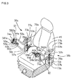
- Fig. 3 is a figure showing an operating apparatus of the first embodiment.
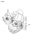
- a operator's seat 49 is installed in the operator cab 4, with an operating device 50a being provided on the right side forward of the operator's seat 49 and an operating device 50b being provided on the left side forward thereof.
- the operating device 50a is an operating device for the first front working machine A, while the operating device 50b is an operating device for the second front working machine B.
- the operating device 50a comprises: an operating arm bracket 51a that is provided on the right side of the operator's seat 49; an operating arm 52a that is mounted to this operating arm bracket 51a so as to swing freely to the right and left around a central swing axis line 73a, and that issues commands for the swing post 7a to swing right and left; an operating lever 54a that is mounted to the end portion of this operating arm 52a so as to extend horizontally and that is able to rotate freely up, down, forward, and backward, and that is used for issuing operating commands for motion of the boom 10a and the arm 12a; a working tool twist grip 55a that is mounted around the outside of this operating lever 54a so as to rotate freely about the axis of the operating lever 54a, and that is used for issuing commands for rotation of the working tool 14a; and a working tool operation switch 56a that is mounted at the end portion of the operating lever 54a, and that issues commands for the working tool 14a to start and to stop.
- the operating device 50a comprises: an operating arm displacement detector 57a that is mounted to the operating arm bracket 51a, and that detects the amount of swing displacement of the operating arm 52a and generates a signal representative thereof; an operating lever up/down direction displacement detector 581a that is mounted to the operating arm 52a, and that detects the amount of displacement of the operating lever 54a in the up/down direction and generates a signal representative thereof; and an operating lever forward/backward direction displacement detector 582a that, in a similar manner to the above, detects the amount of displacement of the operating lever 54a in the forward/backward direction and generates a signal representative thereof.
- the operating device 50a comprises: a twist grip displacement detector 59a that is provided to the operating lever 54a, and that detects the amount of rotational displacement of the working tool twist grip 55a and generates a signal representative thereof; and an operation switch displacement detector 60a that is provided to the working tool twist grip 55a, and that detects the amount of displacement of the working tool operation switch 56a and generates a signal representative thereof.
- the operating device 50b is provided in a similar manner to the operating device 50a, but on the left side of the operator's seat.
- the reference symbols for the members of the operating device 50b are the same as those for the corresponding members of the operating device 50a, except with "b" substituted for "a”, and accordingly detailed explanation thereof will be omitted.
- An operating lever selection switch 61 is a switch for, when a dual-arm synchronization mode is set as will be described hereinafter, selecting whether both the first front working machine A and the second front working machine B should be operated by the right side operating device 50a, or both the first front working machine A and the second front working machine B should be operated by the left side operating device 50b.
- the selection position that makes it possible to operate both the first front working machine A and also the second front working machine B with the right side operating device 50a is called the "right side operating device selection position".
- the operating lever selection switch 61 the selection position that makes it possible to operate both the first front working machine A and also the second front working machine B with the left side operating device 50b is called the "left side operating device selection position".
- the operating lever selection switch 61 may, for example, be provided near the end of the operating arm 52a.
- a dual-arm synchronization mode switch 62 is a switch for selecting whether to establish the dual-arm synchronization mode, or to establish a normal mode that will be described hereinafter, and this switch may be provided, for example, near the end of the operating arm 52b.
- the normal mode and the dual-arm synchronization mode are provided as operational modes for the first front working machine A and the second front working machine B.
- the normal mode is an operational mode for operating the first front working machine A with the right side operating device 50a, and operating the second front working machine B with the left side operating device 50b. Accordingly, if the operational mode is set to the normal mode by operation of this dual-arm synchronization mode switch 62, then the operation of the first front working machine A and the second front working machine B becomes similar to the operation of a prior art type two arm work machine. It should be understood that the details of the operation of the first front working machine A and the second front working machine B during the normal mode will be described hereinafter.
- the dual-arm synchronization mode is an operational mode in which it is possible to perform operation as described in (a) and (b) below.
- the operator sits in the operator's seat 49, rests his elbow joints upon elbow joint support portions 77a and 77b of arm rests 53a and 53b on the operating arms 52a and 52b, grasps the working tool twist grips 55a and 55b with his palms, and places his fingers upon the working tool operation switches 56a and 56b.
- the pivoting speed of the boom 10a or of the boom 10b bears a monotonically increasing relationship to the displacement amount of the operating lever 54a or of the operating lever 54b, for example a proportional relationship, so that the displacement of the operating lever 54a or of the operating lever 54b controls the speed of pivoting of the boom 10a or 10b.
- the pivoting speed of the arm 12a or of the arm 12b bears a monotonically increasing relationship to the displacement amount of the operating lever 54a or of the operating lever 54b, for example a proportional relationship, so that the displacement of the operating lever 54a or of the operating lever 54b controls the speed of pivoting of the arm 12a or of the arm 12b.
- the operational mode is set to the normal mode, and when the operator rotates the working tool twist grip 55a on the right side around its central rotational axis line 74a with his palm (refer to the arrow sign "z" in Fig. 5 ), then the working tool cylinder 15a of the first front working machine A extends or retracts. Moreover, when the operator rotates the working tool twist grip 55b on the left side around its central rotational axis line 74b with his palm, then the working tool cylinder 15b of the second front working machine B extends or retracts.
- the first working tool 14a or the second working tool 14b (hereinafter simply termed the "working tools” 14a and 14b) is rotated in a rotational direction that agrees with the rotational direction of the working tool twist grip 55a or of the working tool twist grip 55b (refer to the arrow sign "Z" in Fig. 6 ).
- the rotational speed of the working tool 14a or of the working tool 14b bears a monotonically increasing relationship to the rotational displacement amount of the twist grip 55a or of the twist grip 55b, for example a proportional relationship, so that the displacement of the twist grip 55a or of the twist grip 55b controls the speed of rotating of the working tool 14a or of the working tool 14b.
- the grapple cylinder 19a or the grapple cylinder 19b shown in Fig. 4 extends or retracts. Due to this extension or retraction of the grapple cylinder 19a or of the grapple cylinder 19b, the grapple 20a or the grapple 20b opens or closes.
- the opening or closing speed of the grapple 20a or the grapple 20b bears a monotonically increasing relationship to the displacement amount of the working tool operation switch 56a or of the working tool operation switch 56b, for example a proportional relationship, so that the displacement of the working tool operation switch 56a or of the working tool operation switch 56b controls the speed of rotation of the working tool 14a or of the working tool 14b.
- the swing post cylinder 9a or the swing post cylinder 9b extends or retracts. Due to this, the swing post 7a or the swing post 7b is made to swing in the direction that agrees with the direction of displacement of the operating arm 52a or of the operating arm 52b (refer to the arrow sign "W" in Fig. 6 ).
- the swinging speed of the swing post 7a or the swing post 7b bears a monotonically increasing relationship to the displacement amount of the operating arm 52a or of the operating arm 52b, for example a proportional relationship, so that the displacement of the operating arm 52a or of the operating arm 52b controls the speed of swinging of the swing post 7a or the swing post 7b.
- the right boom 10a and the left boom 10b can be pivoted simultaneously (refer to the arrow sign "Y" in Fig. 6 ) by operation either of the right side operating lever 54a or of the left side operating lever 54b in the up/down direction.
- the pivoting speeds of the boom 10a and of the boom 10b bear a monotonically increasing relationship to the displacement amount of the operating lever 54a or of the operating lever 54b, for example a proportional relationship, so that the displacement of the operating lever 54a or of the operating lever 54b controls the speed of pivoting of the boom 10a and of the boom 10b.
- the operational mode is set to the dual-arm synchronization mode, and the left side operation device selection position is selected by the operating lever selection switch 61, and when the operator displaces the left side operating lever 54b in the forward/backward direction with his palm, then the arm cylinder 13a of the first front working machine A and the arm cylinder 13b of the second front working machine B are both extended or retracted.
- operation of the right side operating lever 54a in the forward/backward direction becomes ineffective, so that, even if the right side operating lever 54a is operated in the forward/backward direction, neither the arm cylinder 13a nor the arm cylinder 13b extends or retracts.
- the right and left arms 12a and 12b can be pivoted simultaneously (refer to the arrow sign "X" in Fig. 6 ) by operation of either the right side operating lever 54a or the left side operating lever 54b in the forward/backward direction.
- the pivoting speeds of the arm 12a and of the arm 12b bear a monotonically increasing relationship to the displacement amount of the operating lever 54a or of the operating lever 54b, for example a proportional relationship, so that the displacement of the operating lever 54a or of the operating lever 54b controls the speed of pivoting of the arm 12a and of the arm 12b.
- the operational mode is set to the dual-arm synchronization mode, and the left side operation device selection position is selected by the operating lever selection switch 61, and when the operator rotates the left side working tool twist grip 55b around the central rotational axis line 74b, then the working tool cylinder 15a of the first front working machine A and the working tool cylinder 15b of the second front working machine B are both extended or retracted simultaneously.
- rotational operation of the right side working tool twist grip 55a becomes ineffective, so that, even if the right side working tool twist grip 55a is rotationally operated, neither the working tool cylinder 15a nor the working tool cylinder 15b extends or retracts.
- the right and left working tools 14a and 14b can be rotated simultaneously (refer to the arrow sign "Z" in Fig. 6 ) in rotational directions that agree with the direction of rotational operation of the working tool twist grip 55a or of the working tool twist grip 55b.
- the rotating speeds of the working tool 14a and of the working tool 14b bear a monotonically increasing relationship to the displacement amount of the twist grip 55a or of the twist grip 55b, for example a proportional relationship, so that the displacement of the twist grip 55a or of the twist grip 55b controls the speed of rotating of the working tool 14a and of the working tool 14b.
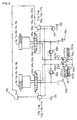
- Fig. 4 is a figure schematically showing hydraulic circuits 150a and 150b that drive the first front working machine A and the second front working machine B.
- 101a and 101b denote variable displacement type hydraulic pumps for providing main hydraulic pressure driven by an engine 40
- 102 denotes a pump for providing pilot hydraulic pressure.
- 103a, 104a, 105a, 106a, and 107a are control valves that supply pressurized hydraulic fluid to, respectively, the swing cylinder 9a, the boom cylinder 11 a, the arm cylinder 13a, the working tool cylinder 15a, and the grapple cylinder 19a of the first front working machine A.
- the control valves 103 a through 107a are respectively controlled by proportional control valves 113a, 114a, 115a, 116a, and 117a on the basis of output signals generated by an operation control device (i.e. a controller) 400 that will be described hereinafter.
- the proportional control valve 113a controls the control valve 103a
- the proportional control valve 114a controls the control valve 104a
- the proportional control valve 115a controls the control valve 105a
- the proportional control valve 116a controls the control valve 106a
- the proportional control valve 117a controls the control valve 107a.
- 108a denotes a main relief valve that regulates the maximum pressure of the hydraulic circuit 150a related to the first working machine A.
- Pressurized hydraulic fluid discharged from the main pump 101a is supplied to the hydraulic cylinders via the control valves 103 a through 107a.
- the operating device 50a When the operating device 50a is operated, due to the operation of the electromagnetic proportional valves 113a through 117a according to the output signals of the controller 400, pilot pressurized hydraulic fluid discharged from the pump 102 is supplied to the corresponding control valves 103a through 107a, so that the spools of the control valves are driven according to the operational amounts of the operating device 50a.
- control valves 103 a through 107a supply pressurized hydraulic fluid discharged from the main pump 101a to the respective cylinders (i.e., actuators) 9a, 11 a, 13a, 15a, and 19a, and thereby drive those cylinders.
- the hydraulic circuit 150b that drives the cylinders (i.e. actuators) 9b, 11b, 13b, 15b, and 19b of the second front working machine B has a structure that is similar to that of the hydraulic circuit 150a relating to the first front working machine A, accordingly detailed explanation thereof will be omitted. Due to these hydraulic circuits 150a and 150b, pressurized hydraulic fluid discharged from the main pump 101a is supplied to the cylinders 9a, 11a, 13a, 15a, and 19a of the first front working machine A, and moreover pressurized hydraulic fluid discharged from the main pump 101b is also supplied to the cylinders 9b, 11b, 13b, 15b, and 19b of the second front working machine B.
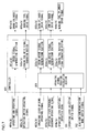
- Fig. 7 is a schematic figure related to an operation control system of the first embodiment.
- Signals 401 a(b) through 404a(b) that are inputted to the controller 400 are operating signals detected by the displacement sensors described above. That is to say, an operating arm operating signal 401a(b) is outputted from an operating arm displacement detector 57a(b).
- An operating lever up/down operating signal 402a(b) is outputted from an operating lever up/down direction displacement detector 581 a(b).
- An operating lever forward/backward operating signal 403a(b) is outputted from an operating lever forward/backward direction displacement detector 582a(b).
- a operating lever rotational operation signal 404a(b) is outputted from a twist grip displacement detector 59a(b).
- an operation switch operating signal 405a(b) is outputted from an operation switch displacement detector 60a(b).
- an operating lever selection switch signal 701 is outputted from the operating lever selection switch 61.
- a dual-arm synchronization mode switch signal 702 is outputted from the dual-arm synchronization mode switch 62.
- Signals 601a(b) through 605a(b) outputted by the controller 400 are drive signals that drive, respectively, the swing cylinder 9a(b), the boom cylinder 11a(b), the arm cylinder 13a(b), the working tool cylinder 15a(b), and the grapple cylinder 19a(b) described above. That is to say, a swing cylinder drive signal 601 a(b) is outputted to the proportional control valve 113a(b) of Fig. 4 , a boom cylinder drive signal 602a(b) is outputted to the proportional control valve 114a(b) of Fig. 4 , and an arm cylinder drive signal 603a(b) is outputted to the proportional control valve 115a(b) of Fig. 4 .
- a working tool cylinder drive signal 604a(b) is outputted to the proportional control valve 116a(b) of Fig. 4
- a working tool drive signal 605a(b) is outputted to the proportional control valve 117a(b) of Fig. 4 .
- the reference symbols 501a(b) through 505a(b) within the controller 400 denote drive signal generation sections that calculate the drive signals described above from the operating signals described above. That is to say, a swing signal generation section 501a(b) generates and outputs the swing cylinder drive signal 601a(b), a boom drive signal generation section 502a(b) generates and outputs the boom cylinder drive signal 602a(b), and an arm drive signal generation section 503a(b) generates and outputs the arm cylinder drive signal 603a(b).
- a working tool rotation signal generation section 504a(b) generates and outputs the working tool cylinder drive signal 604a(b), while a working tool drive signal generation section 505a(b) generates and outputs the working tool drive signal 605a(b).
- Fig. 8 is a schematic figure related to signal processing performed by the signal generation sections 501a(b) through 505a(b), and schematically shows relationships between the operating signals described above and the drive signals described above. Cylinder speed command values that are proportional to the amounts of operation of the operating levers 54a(b) and so on are calculated as drive signals by the drive signal generation sections 501a(b) through 505a(b). It should be understood that neutral zones are set, in order to prescribe operational amounts for operating the levers to become effective.
- an input signal 701 is a signal that specifies the set state of the operating lever selection switch 61, and this signal is outputted from the operating lever selection switch 61.
- an input signal 702 is a signal that specifies the set state of the dual-arm synchronization mode switch 62, and this signal is outputted from the dual-arm synchronization mode switch 62.
- the set states of the input signals 701 and 702 can be changed as appropriate by the operator operating the operating lever selection switch 61 and the dual-arm synchronization mode switch 62 respectively.
- each of the input signals 402a(b) through 404a(b) from the operating levers and so on, the operating lever selection switch signal 701, and the dual-arm synchronization mode switch signal 702 is inputted to an operating signal equating calculation section 801 that will be described hereinafter.
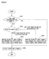
- Fig. 9 is a flow chart showing the flow of processing by the operating signal equating calculation section 801.
- a program that performs the processing shown in Fig. 9 is started, and is repeatedly executed by the operating signal equating calculation section 801.
- the dual-arm synchronization mode switch signal 702 specifying the set state of the dual-arm synchronization mode switch 62 is read in, and a decision is made as to whether or not the operational mode is set to the dual-arm synchronization mode.
- step S902 If an affirmative decision is reached in the step S901, in other words if the operational mode is set to the dual-arm synchronization mode and synchronization of the two arms is permitted, then the flow of control proceeds to a step S902.
- step S902 the operating lever selection switch signal 701 is read in, and a decision is made as to whether the selected position of the operating lever selection switch 61 is the right side operating device selection position or is the left side operating device selection position.
- step S902 If in the step S902 it is decided that the selected position of the operating lever selection switch 61 is the right side operating device selection position, then the flow of control proceeds to a step S903, processing is performed to overwrite the operating signal of the operating lever 54b with the operating signal of the operating lever 54a, and processing is performed to overwrite the operating signal of the working tool twist grip 55b with the operating signal of the working tool twist grip 55a.
- processing is implemented to replace the values of the input signals 402b through 404b, irrespective of these values, with the values of the input signals 402a through 404a (thus making them the same i.e. equating them).
- the operating lever up/down operating signal 402b is replaced, irrespective of its value, with the value of the operating lever up/down signal 402a.
- the operating lever forward/backward operating signal 402b is replaced, irrespective of its value, with the value of the operating lever forward/backward operating signal 403a.
- the twist grip rotational operation signal 404b is replaced, irrespective of its value, with the value of the twist grip rotational operation signal 404a.
- the operating lever up/down operating signal 402a, the operating lever forward/backward operating signal 403a, and the twist grip rotational operation signal 404a are promoted to be common signals in order to drive both the left and the right actuators together using those common signals.
- the flow of control is transferred to a step S905, and the operating signals after the processing in the step S903 are outputted to the signal generation sections 502a through 504a and to the signal generation sections 502b through 504b.
- the operating lever up/down operating signal 402a is outputted to the boom drive signal generation section 502a.
- the operating lever forward/backward operating signal 403a is outputted to the arm drive signal generation section 503 a.
- the twist grip rotational operation signal 404a is outputted to the working tool rotation signal generation section 504a.
- the operating lever up/down operating signal 402a is outputted to the boom drive signal generation section 502b, instead of the operating lever up/down operating signal 402b.
- the operating lever forward/backward operating signal 403a is outputted to the arm drive signal generation section 503b, instead of the operating lever forward/backward operating signal 403b.
- the operating lever rotational operational signal 404a is outputted to the working tool rotation signal generation section 504b, instead of the twist grip rotational operation signal 404b. And when the step S905 has been executed, this program terminates.
- step S902 it is decided that the selected position of the operating lever selection switch 61 is the left side operating device selection position, then the flow of control proceeds to a step S904, processing is performed to overwrite the operating signal of the operating lever 54a with the operating signal of the operating lever 54b, and processing is performed to overwrite the operating signal of the working tool twist grip 55a with the operating signal of the working tool twist grip 55b.
- processing is implemented to replace the values of the input signals 402a through 404a, irrespective of these values, with the values of the input signals 402b through 404b (i.e. to make them the same).
- the operating lever up/down operating signal 402a is replaced, irrespective of its value, with the value of the operating lever up/down signal 402b.
- the operating lever forward/backward operating signal 402a is replaced, irrespective of its value, with the value of the operating lever forward/backward operating signal 403b.
- the twist grip rotational operation signal 404a is replaced, irrespective of its value, with the value of the twist grip rotational operation signal 404b.
- the operating lever up/down operating signal 402b, the operating lever forward/backward operating signal 403b, and the twist grip rotational operation signal 404b are promoted to be common signals in order to drive both the left and the right actuators together using those common signals.
- the flow of control is transferred to the step S905, and the operating signals after the processing in the step S904 are outputted to the signal generation sections 502a through 504a and to the signal generation sections 502b through 504b.
- the operating lever up/down operating signal 402b is outputted to the boom drive signal generation section 502a, instead of the operating lever up/down operating signal 402a.
- the operating lever forward/backward operating signal 403b is outputted to the arm drive signal generation section 503a, instead of the operating lever up/down operating signal 402a.
- the twist grip rotational operation signal 404a is outputted to the working tool rotation signal generation section 504a, instead of the twist grip rotational operation signal 404a.
- the operating lever up/down operating signal 402b is outputted to the boom drive signal generation section 502b.
- the operating lever forward/backward operating signal 403b is outputted to the arm drive signal generation section 503b.
- the operating lever rotational operational signal 404b is outputted to the working tool rotation signal generation section 504b.
- step S901 if a negative decision has been reached in the step S901, in other words if the operational mode is set to the normal mode so that dual-arm synchronization is not permitted, then the flow of control is transferred to the step S905. In other words, if a negative decision has been reached in the step S901, then processing for overwriting the operating signals such as that performed in the steps S903 and S904 is not performed, but each of the input signals 402a through 404a is outputted to the corresponding signal generation sections 502a through 504a, and each of the input signals 402b through 404b is outputted to the corresponding signal generation sections 502b through 504b.
- the operating lever up/down operating signal 402a is outputted to the boom drive signal generation section 502a.
- the operating lever forward/backward operating signal 403a is outputted to the arm drive signal generation section 503a.
- the twist grip rotational operation signal 404a is outputted to the working tool rotation signal generation section 504a.
- the operating lever up/down operating signal 402b is outputted to the boom drive signal generation section 502b.
- the operating lever forward/backward operating signal 403b is outputted to the arm drive signal generation section 503b.
- the twist grip rotational operation signal 404b is outputted to the working tool rotation signal generation section 504b.
- the attitude of the first working machine A is defined by the swing angle of the swing post 7a with respect to the revolving upperstructure 3, the pivoting angle of the boom 10a with respect to the swing post 7a, the pivoting angle of the arm 12a with respect to the boom 10a, and the pivoting angle of the first working tool 14a with respect to the arm 12a.
- the attitude of the second working machine B is defined by the swing angle of the swing post 7b with respect to the revolving upperstructure 3, the pivoting angle of the boom 10b with respect to the swing post 7b, the pivoting angle of the arm 12b with respect to the boom 10a, and the pivoting angle of the second working tool 14b with respect to the arm 12b.
- this work machine 200 does not intentionally make the attitude of the first front working machine A and the attitude of the second front working machine B be different, during normal working, the initial attitude of the first front working machine A and the initial attitude of the second front working machine B will be approximately the same. Due to this, during normal working, the requirement is low for making a decision, as a condition for starting dual-arm synchronized operation, as to whether or not the initial attitude of the first front working machine A and the initial attitude of the second front working machine B are approximately the same. Accordingly with the work machine 200 of this first embodiment it is not proposed, as a condition for starting dual-arm synchronized operation, that the initial attitudes of the first front working machine A and of the second front working machine B are obtained.
- the work machine 200 according to the first embodiment described above provides the following operations and beneficial effects.
- FIG. 10 A second embodiment of the dual-arm work machine according to the present invention will now be explained with reference to Figs. 10 through 13 .
- structural elements that are the same as in the first embodiment will be denoted by the same reference symbols, and the explanation will principally focus upon the features of difference. Points that are not particularly explained are the same as in the first embodiment.
- the feature of difference from the first embodiment is that a decision is made as to whether to make dual-arm synchronized operation possible, on the basis of the directions of operation of the operating levers 54a and 54b and the twist grips 55a and 55b.
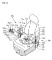
- Fig. 10 is a figure showing the operating apparatus of the second embodiment.
- the difference between the operating devices 50a and 50b of the second embodiment and those of the first embodiment is that the operating lever selection switch 61 and the dual-arm synchronization mode switch 62 are not provided.
- the right and left booms 10a and 10b and the right and left arms 12a and 12b are rotated simultaneously according to the operating amount of that operating lever, among the right side operating lever 54a and the left side operating lever 54b, whose amount of displacement (i.e. amount of operation) is the greater.
- the right and left booms 10a and 10b are rotated simultaneously according to the operating amount of that operating lever, among the right side operating lever 54a and the left side operating lever 54b, whose amount of operation in the up/down direction is the greater.
- the right and left arms 12a and 12b are rotated simultaneously according to the operating amount of that operating lever, among the right side operating lever 54a and the left side operating lever 54b, whose amount of operation in the forward/backward direction is the greater. Furthermore, the right and left working tools 14a and 14b are rotated simultaneously according to the amount of rotational operation of that twist grip, among the right side twist grip 55a and the left side twist grip 55b, whose displacement amount (i.e. amount of rotational operation) is the greater.
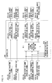
- Fig. 11 is a schematic figure related to the operation control system of the second embodiment.
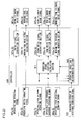
- An operating direction determination section 810 and an operating signal equating calculation section 811 are provided to a controller 400.
- the input signals 402a(b) through 404a(b) from the operating levers and so on are read in to the operating direction determination section 810.
- the input signals 402a(b) through 404a(b) from the operating levers and so on and the result of determination by the operating direction determination section 810 are inputted to the operating signal equating calculation section 811.
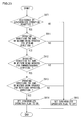
- Fig. 12 is a flow chart showing the flow of processing by the operating direction determination section 810.
- a program that performs the processing shown in Fig. 12 is started, and is repeatedly executed by the operating direction determination section 810. It should be understood that this program is a program for making a decision as to whether or not all of the conditions (2-1) through (2-3) described above are satisfied.
- a step S911 it is determined whether or not the condition (2-1) described above is satisfied, on the basis of the operating lever up/down operating signal 402a and the operating lever up/down operating signal 402b. If it is determined that the condition (2-1) described above is satisfied, in other words if it is determined that the operating directions in the up/down direction of both the right side operating lever 54a and the left side operating lever 54b are the same, or that neither the right side operating lever 54a nor the left side operating lever 54b is being operated in the up/down direction, then the flow of control proceeds to a step S912.
- step S912 it is determined whether or not the condition (2-2) described above is satisfied, on the basis of the operating lever forward/backward operating signal 403a and the operating lever forward/backward operating signal 403b. If it is determined that the condition (2-2) described above is satisfied, in other words if it is determined that the operating directions in the forward/backward direction of both the right side operating lever 54a and the left side operating lever 54b are the same, or that neither the right side operating lever 54a nor the left side operating lever 54b is being operated in the forward/backward direction, then the flow of control proceeds to a step S913.
- step S913 it is determined whether or not the condition (2-3) described above is satisfied, on the basis of the twist grip rotational operation signal 404a and the twist grip rotational operation signal 404b. If it is determined that the condition (2-3) described above is satisfied, in other words if it is determined that the operating directions (i.e. the directions of rotational operation) of both the right side twist grip 55a and the left side twist grip 55b are the same, or that neither the right side twist grip 55a nor the left side twist grip 55b is being rotationally operated, then the flow of control proceeds to a step S914.
- the operating directions i.e. the directions of rotational operation
- step S914 it is considered that synchronized operation is to be performed, so that processing is performed to set a synchronized operation flag to ON.
- this program terminates.
- the operating direction determination section 810 also functions as a synchronized operation decision section that makes a decision as to whether or not the operating directions of the right side operating lever 54a and the left side operating lever 54b are the same or not, and whether the operating directions of the right side twist grip 55a and the left side twist grip 55b are the same or not.
- Fig. 13 is a flow chart showing the flow of processing by the operating signal equating calculation section 811.
- a program that performs the processing shown in Fig. 13 is started, and is repeatedly executed by the operating signal equating calculation section 811.
- the flow of control proceeds to a step S922.
- step S922 comparison together of the magnitudes of the operating amounts in the up/down direction of the operating lever 54a and the operating lever 54b is performed. And, if the operating amount in the up/down direction of the right side operating lever 54a is greater than the operating amount in the up/down direction of the left side operating lever 54b, then the flow of control proceeds to a step S923, whereas if it is not then the flow of control is transferred to a step S924.
- processing is performed to overwrite the up/down operating signal 402b of the operating lever 54b with the up/down operating signal 402a of the operating lever 54a; in concrete terms, processing is performed to replace the value of the input signal 402b, irrespective of its value, with the value of the input signal 402a (i.e. to make them be the same).
- processing is performed to overwrite the up/down operating signal 402a of the operating lever 54a with the up/down operating signal 402b of the operating lever 54b; in concrete terms, processing is performed to replace the value of the input signal 402a, irrespective of its value, with the value of the input signal 402b (i.e. to make them be the same).
- step S925 comparison together of the magnitudes of the operating amounts in the forward/backward direction of the operating lever 54a and the operating lever 54b is performed. And, if the operating amount in the forward/backward direction of the right side operating lever 54a is greater than the operating amount in the forward/backward direction of the left side operating lever 54b, then the flow of control proceeds to a step S926, whereas if it is not then the flow of control is transferred to a step S927.
- processing is performed to overwrite the forward/backward operating signal 403b of the operating lever 54b with the forward/backward operating signal 403a of the operating lever 54a; in concrete terms, processing is performed to replace the value of the input signal 403b, irrespective of its value, with the value of the input signal 403a (i.e. to make them be the same).
- processing is performed to overwrite the forward/backward operating signal 403a of the operating lever 54a with the forward/backward operating signal 403b of the operating lever 54b; in concrete terms, processing is performed to replace the value of the input signal 403a, irrespective of its value, with the value of the input signal 403b (i.e. to make them be the same).
- step S928 comparison together of the magnitudes of the operating amounts (i.e. the amounts of rotation) of the working tool twist grip 55a and the working tool twist grip 55b is performed. And, if the operating amount of the right side working tool twist grip 55a is greater than the operating amount of the left side working tool twist grip 55b, then the flow of control proceeds to a step S929, whereas if it is not then the flow of control is transferred to a step S931.
- processing is performed to overwrite the twist grip rotational operation signal 404b of the working tool twist grip 55b with the twist grip rotational operation signal 404a of the working tool twist grip 55a; in concrete terms, processing is performed to replace the value of the input signal 404b, irrespective of its value, with the value of the input signal 404a (i.e. to make them be the same).
- processing is performed to overwrite the twist grip rotational operation signal 404a of the working tool twist grip 55a with the twist grip rotational operation signal 404b of the working tool twist grip 55b; in concrete terms, processing is performed to replace the value of the input signal 404a, irrespective of its value, with the value of the input signal 404b (i.e. to make them be the same).
- step S929 or the step S931 the flow of control is transferred to a step S932, and the operating signals after the processing of the steps described above are outputted to the signal generation sections 502a through 504a and to the signal generation sections 502b through 504b.
- the operating lever up/down operating signal 402a and the operating lever up/down operating signal 402b are compared together, and the larger one of these signals is outputted to the boom drive signal generation sections 502a and 502b.
- the operating lever forward/backward operating signal 403a and the operating lever forward/backward operating signal 403b are compared together, and the larger one of these signals is outputted to the arm drive signal generation sections 503a and 503b.
- twist grip rotational operation signal 404a and the twist grip rotational operation signal 404b are compared together, and the larger one of these signals is outputted to the working tool rotation signal generation sections 504a and 504b. And, when this step S932 has been executed, the program terminates.
- step S921 it is decided that the synchronized operation flag that is the result of processing by the operating direction determination section 810 is set to OFF, then the flow of control is transferred to the step S932.
- processing such as that performed by the steps described above to overwrite some of the operating signals is not performed, but simply the various input signals 402a through 404a are outputted to the corresponding signal generation sections 502a through 504a, and similarly the various input signals 402b through 404b are outputted to the corresponding signal generation sections 502b through 504.
- the operating lever up/down operating signal 402a is outputted to the boom drive signal generation section 502a.
- the operating lever forward/backward operating signal 403a is outputted to the arm drive signal generation section 503a.
- the twist grip rotational operation signal 404a is outputted to the working tool rotation signal generation section 504a.
- the operating lever up/down operating signal 402b is outputted to the boom drive signal generation section 502b.
- the operating lever forward/backward operating signal 403b is outputted to the arm drive signal generation section 503b.
- the twist grip rotational operation signal 404b is outputted to the working tool rotation signal generation section 504b.
- the right and left booms 10a and 10b and the right and left arms 12a and 12b are pivoted simultaneously according to the operating amounts of that operating lever, among the right and left operating levers 54a and 54b, whose operating amounts in the up/down direction and in the forward/backward direction are the greater.
- the working tools 14a and 14b are pivoted simultaneously corresponding to the amount of rotation of that twist grip, among the right and left twist grips 55a and 55b, whose amount of rotation is the greater.
- FIG. 14 A third embodiment of the dual-arm work machine according to the present invention will now be explained with reference to Fig. 14 .
- structural elements that are the same as in the first or the second embodiment will be denoted by the same reference symbols, and the explanation will principally focus upon the features of difference. Points that are not particularly explained are the same as in the first or the second embodiment.
- the principal aspect of difference from the second embodiment is that, when dual-arm synchronized operation has become possible, the right and left booms 10a and 10b, arms 12a and 12b, and working tools 14a and 14b are pivoted simultaneously on the basis of the average values of the displacement amounts (i.e. the amounts of operation) of the right side operating lever 54a and the left side operating lever 54b, and the average value of the displacement amounts (i.e. the amounts of rotational operation) of the right side twist grip 55a and the left side twist grip 55b.
- the average values of the displacement amounts i.e. the amounts of operation
- the operating apparatus of this third embodiment is the same as the operating apparatus of the second embodiment. Moreover, with this second embodiment, in a similar manner to the case with the second embodiment, dual-arm synchronized operation becomes possible when all of the conditions (2-1) through (2-3) are satisfied. And, when all of the conditions (2-1) through (2-3) are satisfied and dual-arm synchronized operation becomes possible, the right and left booms 10a and 10b, arms 12a and 12b, and working tools 14a and 14b are pivoted simultaneously according to the average values of the amounts of displacement (i.e. amounts of operation) of the right side operating lever 54a and the left side operating lever 54b, and according to the average value of the amounts of displacement (i.e. amounts of rotational operation) of the right side twist grip 55a and the left side twist grip 55b.
- the average values of the amounts of displacement i.e. amounts of operation
- the right and left booms 10a and 10b are simultaneously pivoted according to the average value of the operating amounts in the up/down direction of the right side operating lever 54a and the left side operating lever 54b.
- the right and left arms 12a and 12b are simultaneously pivoted according to the average value of the operating amounts in the forward/backward direction of the right side operating lever 54a and the left side operating lever 54b.
- the right and left working tools 14a and 14b are simultaneously pivoted according to the average value of the amounts of rotational operation of the right side twist grip 55a and the left side twist grip 55b.
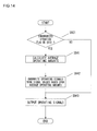
- Fig. 14 is a flow chart showing the flow of processing by the operating signal equating calculation section 811 in this third embodiment.
- a program that performs the processing shown in Fig. 14 is started, and is repeatedly executed by the operating signal equating calculation section 811.
- the step S921 is the same as the step S921 in Fig. 13 for the third embodiment. After the step S921 has been executed, the flow of control is transferred to a step S941.
- the average values of the operating amounts of the right side operating lever 54a and of the left side operating lever 54b, and the average value of the amounts of rotational operation of the right side twist grip 55a and of the left side twist grip 55b are calculated (in the following, these average values will simply be termed the "average operating amounts").
- the average of the operating amounts of the right side operating lever 54a and of the left side operating lever 54b in the up/down direction the average of the operating amounts of the right side operating lever 54a and of the left side operating lever 54b in the forward/backward direction, and the average of the operating amounts of the right side twist grip 55a and of the left side twist grip 55b are calculated.
- step S941 When the step S941 has been performed the flow of control proceeds to a step S942, in which processing is performed to calculate the values of operating signals corresponding to the average operating amounts calculated in the step S941, and to overwrite these over the corresponding input signals 402a through 404a and input signals 402b through 404b.
- processing is performed to replace the values of the input signals 402a through 404a and the values of the input signals 402b through 404b, irrespective of their values, with the values of operating signals that respectively correspond to the averages of their respective operating amounts (i.e., processing to make them be the same).
- step S942 When the step S942 has been executed the flow of control proceeds to a step S943, and the operating signals after the processing of the step S942 described above are outputted to the signal generation sections 502a through 504a and to the signal generation sections 502b through 504b.
- an operating signal corresponding to the average of the operating amounts in the up/down direction of the operating levers 54a and 54b is outputted to the boom drive signal generation sections 502a and 502b.
- an operating signal corresponding to the average of the operating amounts in the forward/backward direction of the operating levers 54a and 54b is outputted to the arm drive signal generation sections 503a and 503b.
- an operating signal corresponding to the average of the operating amounts of the twist grips 55a and 55b is outputted to the working tool rotation signal generation sections 504a and 504b.
- step S921 it is decided that the synchronized operation flag, this being the result of processing by the operating direction determination section 810, is set to OFF, then the flow of control is transferred to the step S943.
- processing such as that performed by the step S942 described above to overwrite the operating signals is not performed, but simply the various input signals 402a through 404a are outputted to the corresponding signal generation sections 502a through 504a, and similarly the various input signals 402b through 404b are outputted to the corresponding signal generation sections 502b through 504.
- the operating lever up/down operating signal 402a is outputted to the boom drive signal generation section 502a.
- the operating lever forward/backward operating signal 403a is outputted to the arm drive signal generation section 503a.
- the twist grip rotational operation signal 404a is outputted to the working tool rotation signal generation section 504a.
- the operating lever up/down operating signal 402b is outputted to the boom drive signal generation section 502b.
- the operating lever forward/backward operating signal 403b is outputted to the arm drive signal generation section 503b.
- the twist grip rotational operation signal 404b is outputted to the working tool rotation signal generation section 504b.
- FIG. 15 A fourth embodiment of the dual-arm work machine according to the present invention will now be explained with reference to Figs. 15 and 16 .
- structural elements that are the same as in the first through the third embodiments will be denoted by the same reference symbols, and the explanation will principally focus upon the features of difference. Points that are not particularly explained are the same as in the third embodiment.
- the principal aspect of difference from the third embodiment is that a decision is made as to whether or not to make dual-arm synchronized operation possible, on the basis of the operating directions and the operating amounts (in other words, the operating vectors) of the operating levers 54a and 54b and of the twist grips 55a and 55b.
- the operating apparatus of the fourth embodiment is the same as the operating apparatus of the second and third embodiments.
- the right and left booms 10a and 10b, the right and left arms 12a and 12b, and the right and left working tools 14a and 14b are pivoted simultaneously according to the average values of the displacement amounts (i.e. the operating amounts) of the right side operating lever 54a and the left side operating lever 54b, and according to the average value of the displacement amounts (i.e. the amounts of rotational operation) of the right side twist grip 55a and the left side twist grip 55b.
- Fig. 15 is a schematic figure relating to the operation control system of the fourth embodiment.
- an operating vector determination section 820 and a threshold value setting section 821 are provided to a controller 400.
- the input signals 402a(b) through 404a(b) from the operating levers and so on are inputted to the operating vector determination section 820.
- the processing performed by the operating vector determination section 820 will be described hereinafter.
- the threshold value setting section 821 is a setting unit for setting threshold values for deciding whether or not the operating vectors of the right side operating lever 54a and the twist grip 55a, and of the left side operating lever 54b and the twist grip 55b, are approximately the same; and the threshold values that are stored therein may, for example, be set in advance in the factory before shipment of the work machine 200. It should be understood that the threshold values may be set as desired: they may also be set using an external setting device, such as for example a personal computer or the like.
- the threshold values that are stored in the threshold value setting section 821 may, for example, include a threshold value related to the difference between the operating vectors in the up/down direction of the operating lever 54a and of the operating lever 54b, a threshold value related to the difference between the operating vectors in the forward/backward direction of the operating lever 54a and of the operating lever 54b, and a threshold value related to the difference between the operating vectors of the twist grip 55a and of the twist grip 55b.
- Fig. 16 is a flow chart for the flow of processing by the operating vector determination section 820.
- a program that performs the processing shown in Fig. 16 is started, and is repeatedly executed by the operating vector determination section 820. It should be understood that this program is a program for making a decision as to whether or not all of the conditions (4-1) through (4-3) described above are satisfied.
- step S952 on the basis of the operating lever forward/backward operating signal 403a and the operating lever forward/backward operating signal 403b, a decision is made as to whether or not the condition (4-2) described above is satisfied. If it is decided that the condition (4-2) described above is satisfied, in other words that the difference between the operating vectors in the forward/backward direction of the right side operating lever 54a and of the left side operating lever 54b is within the predetermined threshold value, or that neither the right side operating lever 54a nor the left side operating lever 54b is being operated in the forward/backward direction, then the flow of control proceeds to the step S953.
- step S953 on the basis of the twist grip rotational operation signal 404a and the twist grip rotational operation signal 404b, a decision is made as to whether or not the condition (4-3) described above is satisfied. If it is decided that the condition (4-3) described above is satisfied, in other words that the difference between the operating vectors of the right side twist grip 55a and the left side twist grip 55b is within the predetermined threshold value, or that neither the right side twist grip 55a nor the left side twist grip 55b is being rotationally operated, then the flow of control proceeds to the step S954.
- step S954 it is considered that the operating vectors of the operating levers 54a and 54b, and the operating vectors of the twist grips 55a and 55b, are approximately equal on right and left, and that accordingly synchronized operation is to be performed, so that processing is performed to set the synchronized operation flag to ON.
- this program terminates.
- step S955 If a negative decision is reached in the step S951, a negative decision is reached in the step S952, or a negative decision is reached in the step S953, then the flow of control is transferred to the step S955.
- this step S955 when either the operating vectors of the operating levers 54a and 54b or the operating vectors of the twist grips 55a and 55b or both are in operation, and the difference of those operating vectors between right and left is greater than the predetermined threshold value, it is considered that synchronized operation is not to be performed, and accordingly processing is performed to set the synchronized operation flag is set to OFF.
- this step S955 has been executed, this program terminates.
- a fifth embodiment of the dual-arm work machine according to the present invention will now be explained with reference to Figs. 17 through 20 .
- structural elements that are the same as in the first through the fourth embodiments will be denoted by the same reference symbols, and the explanation will principally focus upon the features of difference. Points that are not particularly explained are the same as in the second embodiment.
- the principal aspect of difference from the second embodiment is that it is arranged for dual-arm synchronized operation to become possible only if the initial attitude of the first front working machine A and the initial attitude of the second front working machine B are approximately the same.
- the operating apparatus of the fifth embodiment is the same as the operating apparatus of the second through the fourth embodiments.
- angle sensors 131a through 134a and 131b through 134b are provided to the work machine 200 of this fifth embodiment.
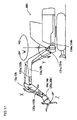
- the angle sensor 131a detects the pivoting angle of the boom 10a with respect to the swing post 7a (refer to the arrow sign Y in Fig. 17 ; hereinafter simply termed the "boom angle a").
- the angle sensor 132a detects the pivoting angle of the arm 12a with respect to the boom 10a (refer to the arrow sign X in Fig. 17 ; hereinafter simply termed the "arm angle a").
- the angle sensor 133a detects the pivoting angle of the first working tool 14a with respect to the arm 12a (refer to the arrow sign Z in Fig.
- the angle sensor 134a detects the swing angle of the swing post 7a with respect to the revolving upperstructure 3 (refer to the arrow sign W in Fig. 17 ; hereinafter simply termed the "swing angle a").
- the angle sensor 131b detects the pivoting angle of the boom 10b with respect to the swing post 7b (refer to the arrow sign Y in Fig. 17 ; hereinafter simply termed the "boom angle b").
- the angle sensor 132b detects the pivoting angle of the arm 12b with respect to the boom 10b (refer to the arrow sign X in Fig. 17 ; hereinafter simply termed the "arm angle b").
- the angle sensor 133b detects the pivoting angle of the second working tool 14b with respect to the arm 12b (refer to the arrow sign Z in Fig. 17 ; hereinafter simply termed the "working tool angle b").
- the angle sensor 134b detects the swing angle of the swing post 7b with respect to the revolving upperstructure 3 (refer to the arrow sign W in Fig. 17 ; hereinafter simply termed the "swing angle b").
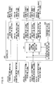
- Fig. 18 is a schematic figure related to the operation control system of this fifth embodiment.
- An attitude determination section 830 and a threshold value setting section 831 are provided to a controller 400.
- Attitude detection signals 710a and 710b are read into the attitude determination section 830.
- the term "attitude detection signals 710a” is a generic term for the angle detection signals outputted from the angle sensors 131a through 134a.
- attitude detection signals 710a that is outputted from the angle sensor 131a
- an arm angle detection signal 712a that is outputted from the angle sensor 132a
- a working tool angle detection signal 713a that is outputted from the angle sensor 133a
- a swing angle detection signal 714a that is outputted from the angle sensor 134a are included in the attitude detection signals 710a.
- the term "attitude detection signals 710b" is a generic term for the angle detection signals outputted from the angle sensors 131b through 133b.
- a boom angle detection signal 711b that is outputted from the angle sensor 131b, an arm angle detection signal 712b that is outputted from the angle sensor 132b, a working tool angle detection signal 713b that is outputted from the angle sensor 133b, and a swing angle detection signal 714b that is outputted from the angle sensor 134b are included in the attitude detection signals 710b.
- the processing performed by the attitude determination section 830 will be described hereinafter.
- the threshold value setting section 831 is a setting unit for setting threshold values for deciding whether or not the initial attitude of the first front working machine A and the initial attitude of the second front working machine B are approximately the same, and the threshold values that are stored therein may, for example, be set in advance in the factory before shipment of the work machine 200. It should be understood that the threshold values may be set as desired: they may also be set using an external setting device, such as for example a personal computer or the like.
- the threshold values that are stored in the threshold value setting section 831 may, for example, include a threshold value related to the difference between the boom angle a and the boom angle b, a threshold value related to the difference between the arm angle a and the arm angle b, a threshold value related to the difference between the working tool angle a and the working tool angle b, a threshold value related to the difference (i.e. the deviation) between the fore and aft direction of the work machine 200 (i.e. its center line 3c in Fig. 2 ) and the swing angle a, and a threshold value related to the difference (i.e. the deviation) between the fore and aft direction of the work machine 200 (i.e. its center line 3c in Fig. 2 ) and the swing angle b.
- attitude determination section 830 On the basis of the attitude detection signals 710a and 710b, a decision is made by the attitude determination section 830 as to whether or not the initial attitude of the first front working machine A and the initial attitude of the second front working machine B are approximately the same. In concrete terms, it is decided that the initial attitude of the first front working machine A and the initial attitude of the second front working machine B are approximately the same, if all of the following conditions (5-1) through (5-5) are satisfied.
- Fig. 19 is a flow chart showing the flow of processing by the operating direction determination section 810.
- the ignition switch not shown in the figures of the working machine 200 is turned to ON, a program that performs the processing shown in Fig. 19 is started, and is repeatedly executed by the operating direction determination section 810.
- a first step S961 it is decided by the attitude determination section 830 whether or not the initial attitude of the first front working machine A and the initial attitude of the second front working machine B are approximately the same. In other words, it is decided whether or not it has been determined by the attitude determination section 830 that all of the conditions (5-1) through (5-5) described above are satisfied. If an affirmative decision is reached in this step S961 then the flow of control is transferred to a step S911, whereas if a negative decision is reached in the step S961 then the flow of control is transferred to a step S915. Since the subsequent steps S911 through S915 are the same as those in the flow of processing by the operating direction determination section 810 of the second embodiment shown in Fig. 12 , accordingly explanation thereof will be omitted.
- FIG. 21 A sixth embodiment of the dual-arm work machine according to the present invention will now be explained with reference to Figs. 21 through 23 .
- structural elements that are the same as in the first through the fifth embodiments will be denoted by the same reference symbols, and the explanation will principally focus upon the features of difference. Points that are not particularly explained are the same as in the second embodiment.
- the principal aspect of difference from the second embodiment is that, even if the operating lever 54a and the operating lever 54b are operated in approximately the same direction, and also the twist grip 55a and the twist grip 55b are operated in the same direction, the assistance of dual-arm synchronized operation is provided only if a switch that permits assistance by dual-arm synchronized operation is operated by the operator.
- Fig. 21 is a figure showing the operating apparatus of the sixth embodiment.
- a dual-arm synchronized operation assistance permission switch 63 is provided, for example near the end of the operating arm 52a.
- This dual-arm synchronized operation assistance permission switch 63 is a switch that is operated by the operator in order to select whether or not to make dual-arm synchronized operation possible (i.e. whether or not to permit assistance by dual-arm synchronized operation), if all of the conditions (2-1) through (2-3) for making dual-arm synchronized operation possible in the second embodiment described above are satisfied.
- this dual-arm synchronized operation assistance permission switch 63 When this dual-arm synchronized operation assistance permission switch 63 is operated by the operator so as to permit assistance by dual-arm synchronized operation, it outputs a synchronized operation assistance permission signal 720 to an operating direction determination section 840 that will be described hereinafter.
- Fig. 22 is a schematic figure related to the operation control system of this sixth embodiment.
- An operating direction determination section 840 is provided to a controller 400, instead of the operating direction determination section 810 of the second embodiment.
- the input signals 402a(b) from the operating levers and so on, and the synchronized operation assistance permission signal 720 from the dual-arm synchronized operation assistance permission switch 63, are inputted to the operating direction determination section 810.
- Fig. 23 is a flow chart showing the flow of processing by the operating direction determination section 840.
- a program that performs the processing shown in Fig. 23 is started, and is repeatedly executed by the operating direction determination section 840. It should be understood that this program is a program for determining whether or not both of the conditions (6-1) and (6-2) described above are satisfied.
- a decision is made as to whether or not the synchronized operation assistance permission signal 720 outputted from the dual-arm synchronized operation assistance permission switch 63 is being received. In other words, a decision is made as to whether or not the condition (6-1) described above is satisfied. If an affirmative decision is reached in the step S97 then the flow of control is transferred to a step S911, whereas if a negative decision is reached in the step S971 the flow of control is transferred to a step S915. Since the subsequent steps from the step S911 through the step S915 are a flow of processing for deciding whether or not the condition (6-2) described above is satisfied, and are the same as the processing flow of the operating direction determination section 810 in the second embodiment as shown in Fig. 12 , accordingly explanation thereof will be omitted.
- the operating direction determination section 840 also functions as a shared drive command generation permission section that, on the basis of the synchronized operation assistance permission signal 720, either permits or prohibits assistance by dual-arm synchronized operation, in other words either permits or prohibits generation and output of shared drive commands for dual-arm synchronized operation.
- the present invention is not to be considered as being limited by the embodiments described above; it includes dual-arm work machines of various constructions that are characterized by comprising: a first front working machine to which a first attachment is mounted; a second working machine to which a second attachment is mounted; a first drive device that drives the first front working machine and the first attachment on the basis of a first drive command from a first operation member; a second drive device that drives the second front working machine and the second attachment on the basis of a second drive command from a second operation member; and a drive command output device that inputs the first and second drive commands, and generates and outputs a shared drive command that drives the first and second drive devices.
Landscapes
- Engineering & Computer Science (AREA)
- Structural Engineering (AREA)
- Mining & Mineral Resources (AREA)
- Civil Engineering (AREA)
- General Engineering & Computer Science (AREA)
- Mechanical Engineering (AREA)
- Robotics (AREA)
- Physics & Mathematics (AREA)
- Fluid Mechanics (AREA)
- Operation Control Of Excavators (AREA)
- Component Parts Of Construction Machinery (AREA)
- Manipulator (AREA)
Abstract
Description
- The present invention relates to a dual-arm work machine that is equipped with working arms respectively on the right side and on the left side of the main body of the work machine.
- A dual-arm work machine that is equipped with working arms respectively on the right side and on the left side of the main body of the work machine is per se known. Operating levers respectively corresponding to the right and left working arms are provided to such a dual-arm working machine. Since actuators that are respectively provided to the right and left working arms are driven by operating these levers, accordingly it is possible to operate the right and left working arms independently (refer to Patent Document #1).
- Furthermore, a control technique for synchronizing the operation of two manipulators is per se known. In this technique, using an operating lever, the operator only performs driving operation of the manipulator on one side (the "master" side), and the operation of the two manipulators is synchronized by control being automatically performed so that the other manipulator (on the "slave" side) automatically tracks this master side manipulator. Here, the slave side is feedback controlled by referring to the joint coordinates on the master side, and by taking them as target values (refer to Patent Document #2).
-
- Patent Document #1: Japanese Laid Open Patent Publication
H11-181815 - Patent Document #2: Japanese Laid Open Patent Publication
H02-271402 - With the work machine described in Patent Document #1, when a work object is grasped by grasping devices that are mounted at the end of each of the right and left working arms, if the amounts of drive of the working arms on the right and left sides are different, then the relative position of the right and left grasping devices changes, and this is undesirable because there is a fear of damage occurring to the work object that is being grasped. This is because, even in the case of an experienced operator, it is difficult to continue operation so as to keep the amounts of operation of the operating levers that operate to drive the right and left working arms equal. Furthermore, with the dual-arm robot described in
Patent Document # 2, while it is possible to synchronize the operation of the two manipulators, there is a response delay, since the slave side operates after the operation of the master side. Due to this, the relative positions of tools that are mounted to the left arm and to the right arm temporarily changes, and this is undesirable because there is a fear that damage will be caused to the work object that is being grasped. Moreover, since it is necessary constantly to monitor the attitudes of the manipulators, accordingly the system becomes complicated and high in cost, and this also is undesirable. - According to the 1st aspect of the present invention, a dual-arm work machine comprises: a first front working machine to which a first attachment is mounted; a second working machine to which a second attachment is mounted; a first drive device that drives the first front working machine and the first attachment based on a first drive command from a first operation member; a second drive device that drives the second front working machine and the second attachment based on a second drive command from a second operation member; and a drive command output device that inputs the first and second drive commands, and generates and outputs a shared drive command that drives the first and second drive devices.
- According to the 2nd aspect of the present invention, in the dual-arm work machine according to the 1st aspect, it is preferred that: the dual-arm work machine further comprises an operation selection unit that can select either the first operation member or the second operation member; and the drive command output device generates and outputs a shared drive command to drive the first and second drive devices, based on the first drive command from the first operation member or the second drive command from the second operation member selected by the operation selection unit.
- According to the 3rd aspect of the present invention, in the dual-arm work machine according to the 1 st aspect, it is preferred that: the dual-arm work machine further comprises a first operating direction determination section that determines an operating direction of the first operation member, a second operating direction determination section that determines an operating direction of the second operation member, and a synchronized operation decision section that makes a decision as to whether or not the operating direction of the first operation member determined by the first operating direction determination section and the operating direction of the second operation member determined by the second operating direction determination section are the same; and if it is decided by the synchronized operation decision section that the operating direction of the first operation member and the operating direction of the second operation member are the same, the drive command output device generates and outputs the shared drive command based on the first drive command from the first operation member or the second drive command from the second operation member.
- According to the 4th aspect of the present invention, in the dual-arm work machine according to the 1st aspect, it is preferred that: the dual-arm work machine further comprises a first operating direction determination section that determines an operating direction of the first operation member, a second operating direction determination section that determines an operating direction of the second operation member, a first operating amount determination section that determines an operating amount of the first operation member, a second operating amount determination section that determines an operating amount of the second operation member, and a synchronized operation decision section that makes a decision as to whether or not the operating direction of the first operation member determined by the first operating direction determination section and the operating direction of the second operation member determined by the second operating direction determination section are the same; and if it is decided by the synchronized operation decision section that the operating direction of the first operation member and the operating direction of the second operation member are the same, the drive command output device generates and outputs the shared drive command based on an average value of the operating amount of the first operation member determined by the first operating amount determination section and an operating amount of the second operation member as determined by the second operating amount determination means.
- According to the 5th aspect of the present invention, in the dual-arm work machine according to the 1st aspect, it is preferred that: the dual-arm work machine further comprises a first operating vector calculation unit that calculates an operating vector of the first operation member, a second operating vector calculation unit that calculates an operating vector of the second operation member, and a synchronized operation decision section that makes a decision as to whether or not the operating vector of the first operation member calculated by the first operating vector calculation unit and the operating vector of the second operation member calculated by the second operating vector calculation unit are approximately the same; and if it is decided by the synchronized operation decision section that the operating vector of the first operation member and the operating vector of the second operation member are approximately the same, the drive command output device generates and outputs the shared drive command based on the first drive command from the first operation member and/or the second drive command from the second operation member.
- According to the 6th aspect of the present invention, in the dual-arm work machine according to any one of the 1 st through 5th aspects, it is preferred that the dual-arm work machine further comprises: a synchronization selection member that is operated in order for a user to select whether or not a movement of the first front working machine and the first attachment and a movement of the second front working machine and the second attachment are to be synchronized or not; and a shared drive command generation permission section that permits generation and output of the shared drive command by the drive command output device if synchronization of the movement of the first front working machine and the first attachment and the movement of the second front working machine and the second attachment is selected by the synchronization selection member, and prohibits generation and output of the shared drive command by the drive command output device if synchronization of the movement of the first front working machine and the first attachment and the movement of the second front working machine and the second attachment is not selected by the synchronization selection member.
- According to the 7th aspect of the present invention, in the dual-arm work machine according to any one of the 1 st through 5th aspects, it is preferred that the dual-arm work machine further comprises: a first attitude detection unit that detects an attitude of the first front working machine and the first attachment; a second attitude detection unit that detects an attitude of the second front working machine and the second attachment; an attitude determination section that determines whether or not the attitude of the first front working machine and the first attachment detected by the first attitude detection unit and the attitude of the second front working machine and the second attachment detected by the second attitude detection unit are approximately the same; and a shared drive command generation permission section that permits generation and output of the shared drive command by the drive command output device when it is decided by the attitude determination section that the attitude of the first front working machine and the first attachment and the attitude of the second front working machine and the second attachment are approximately the same, and prohibits generation and output of the shared drive command by the drive command output device when it is decided by the attitude determination section that the attitude of the first front working machine and the first attachment and the attitude of the second front working machine and the second attachment are not approximately the same.
- According to the 8th aspect of the present invention, in the dual-arm work machine according to the 7th aspect, it is preferred that: the dual-arm work machine further comprises a synchronization selection member that is operated in order for the user to select whether or not the movement of the first front working machine and the first attachment and the movement of the second front working machine and the second attachment are to be synchronized or not; and the shared drive command generation permission section permits generation and output of the shared drive command by the drive command output device when it is decided by the attitude determination section that the attitude of the first front working machine and the first attachment and the attitude of the second front working machine and the second attachment are approximately the same, and synchronization of the movement of the first front working machine and the first attachment and the movement of the second front working machine and the second attachment is selected by the synchronization selection member, and prohibits generation and output of the shared drive command by the drive command output device when it is decided by the attitude determination section that the attitude of the first front working machine and the first attachment and the attitude of the second front working machine and the second attachment are not approximately the same, or synchronization of the movement of the first front working machine and the first attachment and the movement of the second front working machine and the second attachment is not selected by the synchronization selection member.
- According to the present invention, a convenient structure can be implemented for synchronizing the operation of the first front working machine and the first attachment, with the operation of the second front working machine and the second attachment, and accordingly it is possible to provide at low cost a dual-arm work machine that can be applied to a wide range of tasks.
-
- [
Fig. 1] Fig. 1 is a figure showing a dual-arm work machine according to a first embodiment; - [
Fig. 2] Fig. 2 is a figure showing this dual-arm work machine according to the first embodiment; - [
Fig. 3] Fig. 3 is a figure showing an operating apparatus of the first embodiment; - [
Fig. 4] Fig. 4 is a figure schematically showing hydraulic circuitry; - [
Fig. 5] Fig. 5 is a figure for explanation of directions of operation of an operating device; - [
Fig. 6] Fig. 6 is a figure for explanation of pivoting directions of a first front working machine and a second front working machine; - [
Fig. 7] Fig. 7 is a schematic figure related to an operation control system of the first embodiment; - [
Fig. 8] Fig. 8 is a schematic figure related to signal processing performed by various signal generation sections; - [
Fig. 9] Fig. 9 is a flow chart showing the flow of processing of an operating signal equating calculation section of the first embodiment; - [
Fig. 10]Fig. 10 is a figure showing an operating device of a second embodiment; - [
Fig. 11] Fig. 11 is a schematic figure related to an operation control system of the second embodiment; - [
Fig. 12]Fig. 12 is a flow chart showing the flow of processing of an operating direction determination section of the second embodiment; - [
Fig. 13]Fig. 13 is a flow chart showing the flow of processing of an operating signal equating calculation section of the second embodiment; - [
Fig. 14] Fig. 14 is a flow chart showing the flow of processing of an operating signal equating calculation section of a third embodiment; - [
Fig. 15] Fig. 15 is a schematic figure related to an operation control system of a fourth embodiment; - [
Fig. 16] Fig. 16 is a flow chart showing the flow of processing of an operating vector determination section of the fourth embodiment; - [
Fig. 17]Fig. 17 is a figure showing the way in which angle sensors are arranged; - [
Fig. 18] Fig. 18 is a schematic figure related to an operation control system of a fifth embodiment; - [
Fig. 19]Fig. 19 is a flow chart showing the flow of processing of an operating direction determination section of the fifth embodiment; - [
Fig. 20] Fig. 20 is a figure for explanation of a situation in which a task such as carrying a work object in a parallel manner is being performed by a work machine; - [
Fig. 21] Fig. 21 is a figure showing an operating device of a sixth embodiment; - [
Fig. 22]Fig. 22 is a schematic figure related to an operation control system of the sixth embodiment; and - [
Fig. 23] Fig. 23 is a flow chart showing the flow of processing of an operating direction determination section of the sixth embodiment. - A first embodiment of the dual-arm work machine of the present invention will now be explained with reference to
Figs. 1 through 9 .Figs. 1 and2 are figures showing the dual-arm work machine according to the first embodiment. Thework machine 200 of the first embodiment is a work machine that is constructed on the basis of a hydraulic excavator. In thiswork machine 200, a revolving upperstructure 3 is revolvably mounted to alower traveling body 2 having a traveling crawler 1, and anoperator cab 4 is provided near the center line 3c in the transverse direction of this revolving upperstructure 3. As viewed forward from theoperator cab 4, a first front working machine A and a second front working machine B are provided on the right side and on the left side of thecenter line 3C respectively. - The first front working machine A comprises a
swing post 7a that is mounted to the revolving upperstructure 3 on its right side facing forwards so as to swing freely in the right and left directions, aboom 10a that is mounted to thisswing post 7a so as to pivot freely in the up/down direction, anarm 12a that is mounted to thisboom 10a so as to pivot freely in the up/down direction, and agrapple 20a that is one example of a first working tool (i.e. a first attachment) 14a which is mounted to thisarm 12a so as to pivot (i.e. rotate) freely in the up/down direction. In other words, the first front working machine A comprises a freely pivoting joint that connects the revolving upperstructure 3 and theswing post 7a together, a freely pivoting joint that connects theswing post 7a and theboom 10a together, a freely pivoting joint that connects theboom 10a and thearm 12a together, and a freely rotating joint that connects thearm 12a and thegrapple 20a together. - The first front working machine A also comprises a
swing cylinder 9a that is linked to theswing post 7a and to the revolving upperstructure 3 and that causes theswing post 7a to swing right and left, and aboom cylinder 11 a (not shown inFigs. 1 and2 ) that is linked to theswing post 7a and to theboom 10a and that makes theboom 10a pivot up and down. - Moreover, the first front working machine A also comprises an
arm cylinder 13a that is linked to theboom 10a and to thearm 12a and that makes thearm 12a pivot up and down, and aworking tool cylinder 15a that is linked to thisarm 12a and to thegrapple 20a and that makes thegrapple 20a rotate up and down. Here, thegrapple 20a may, as desired, be exchanged for a cutter or a bucket not shown in the figures or the like, or for some other type of working tool. It should be understood that, collectively, theboom 10a and thearm 12a are herein sometimes also termed the "right side front working arm". - The second front working machine B is provided on the left side facing forward of the revolving upperstructure 3. The second front working machine B has a structure similar to that of the first front working machine A. Thus, the reference symbols for the members of the second front working machine B are the same as those for the corresponding members of the first front working machine A, except with "b" substituted for "a". The position of attachment of the
swing post 7b and the shapes and the dimensions of theswing post 7b, theboom 10b, and thearm 12b in the second front working machine B, are the same as the position of attachment of theswing post 7a and the shapes and the dimensions of theswing post 7a, theboom 10a, and thearm 12a in the first front working machine A. Moreover, thegrapple 20b is the same type of working tool (attachment) as the grapple 20a. And the characteristics of the various hydraulic cylinders that drive the various parts of the second front working machine B are also the same as the characteristics of the various corresponding hydraulic cylinders that drive the various parts of the first front working machine A. Accordingly, detailed explanation of the second front working machine B will be omitted. It should be understood that, collectively, theboom 10b and thearm 12b are herein sometimes also termed the "left side front working arm". -
Fig. 3 is a figure showing an operating apparatus of the first embodiment. A operator'sseat 49 is installed in theoperator cab 4, with anoperating device 50a being provided on the right side forward of the operator'sseat 49 and anoperating device 50b being provided on the left side forward thereof. The operatingdevice 50a is an operating device for the first front working machine A, while theoperating device 50b is an operating device for the second front working machine B. The operatingdevice 50a comprises: an operatingarm bracket 51a that is provided on the right side of the operator'sseat 49; anoperating arm 52a that is mounted to thisoperating arm bracket 51a so as to swing freely to the right and left around a centralswing axis line 73a, and that issues commands for theswing post 7a to swing right and left; anoperating lever 54a that is mounted to the end portion of thisoperating arm 52a so as to extend horizontally and that is able to rotate freely up, down, forward, and backward, and that is used for issuing operating commands for motion of theboom 10a and thearm 12a; a workingtool twist grip 55a that is mounted around the outside of this operatinglever 54a so as to rotate freely about the axis of the operatinglever 54a, and that is used for issuing commands for rotation of the workingtool 14a; and a workingtool operation switch 56a that is mounted at the end portion of the operatinglever 54a, and that issues commands for the workingtool 14a to start and to stop. - Furthermore, the operating
device 50a comprises: an operatingarm displacement detector 57a that is mounted to theoperating arm bracket 51a, and that detects the amount of swing displacement of theoperating arm 52a and generates a signal representative thereof; an operating lever up/downdirection displacement detector 581a that is mounted to theoperating arm 52a, and that detects the amount of displacement of the operatinglever 54a in the up/down direction and generates a signal representative thereof; and an operating lever forward/backwarddirection displacement detector 582a that, in a similar manner to the above, detects the amount of displacement of the operatinglever 54a in the forward/backward direction and generates a signal representative thereof. Moreover, the operatingdevice 50a comprises: a twistgrip displacement detector 59a that is provided to the operatinglever 54a, and that detects the amount of rotational displacement of the workingtool twist grip 55a and generates a signal representative thereof; and an operationswitch displacement detector 60a that is provided to the workingtool twist grip 55a, and that detects the amount of displacement of the workingtool operation switch 56a and generates a signal representative thereof. - The operating
device 50b is provided in a similar manner to theoperating device 50a, but on the left side of the operator's seat. Thus, the reference symbols for the members of theoperating device 50b are the same as those for the corresponding members of theoperating device 50a, except with "b" substituted for "a", and accordingly detailed explanation thereof will be omitted. - An operating
lever selection switch 61 is a switch for, when a dual-arm synchronization mode is set as will be described hereinafter, selecting whether both the first front working machine A and the second front working machine B should be operated by the rightside operating device 50a, or both the first front working machine A and the second front working machine B should be operated by the leftside operating device 50b. For this operatinglever selection switch 61, the selection position that makes it possible to operate both the first front working machine A and also the second front working machine B with the rightside operating device 50a is called the "right side operating device selection position". In a similar manner, for the operatinglever selection switch 61, the selection position that makes it possible to operate both the first front working machine A and also the second front working machine B with the leftside operating device 50b is called the "left side operating device selection position". The operatinglever selection switch 61 may, for example, be provided near the end of theoperating arm 52a. - A dual-arm
synchronization mode switch 62 is a switch for selecting whether to establish the dual-arm synchronization mode, or to establish a normal mode that will be described hereinafter, and this switch may be provided, for example, near the end of theoperating arm 52b. In thiswork machine 200 of the first embodiment, the normal mode and the dual-arm synchronization mode are provided as operational modes for the first front working machine A and the second front working machine B. - The normal mode is an operational mode for operating the first front working machine A with the right
side operating device 50a, and operating the second front working machine B with the leftside operating device 50b. Accordingly, if the operational mode is set to the normal mode by operation of this dual-armsynchronization mode switch 62, then the operation of the first front working machine A and the second front working machine B becomes similar to the operation of a prior art type two arm work machine. It should be understood that the details of the operation of the first front working machine A and the second front working machine B during the normal mode will be described hereinafter. - The dual-arm synchronization mode is an operational mode in which it is possible to perform operation as described in (a) and (b) below.
- (a) When the right side operating device selection position is selected by the operating
lever selection switch 61, it is possible to operate the right and leftboom cylinders arm cylinders tool cylinders side operating lever 54a and the right side workingtool twist grip 55a. - (b) When the left side operating device selection position is selected by the operating
lever selection switch 61, it is possible to operate the right and leftboom cylinders arm cylinders tool cylinders side operating lever 54b and the left side workingtool twist grip 55b. - In order to operate the
operating devices seat 49, rests his elbow joints upon elbowjoint support portions arms - When the operational mode is set to the normal mode, and when the operator, who is in the operating attitude described above, displaces the right
side operating lever 54a with his palm in the up/down direction (refer to the arrow sign "y" inFig. 5 ), then theboom cylinder 11 a of the first front working machine A extends or retracts. Moreover, when the operator displaces the leftside operating lever 54b in the up/down direction, then theboom cylinder 11b of the second front working machine B extends or retracts. Due to this, theboom 10a or theboom 10b is made to pivot (refer to the arrow sign "Y" inFig. 6 ). At this time, the pivoting speed of theboom 10a or of theboom 10b bears a monotonically increasing relationship to the displacement amount of the operatinglever 54a or of the operatinglever 54b, for example a proportional relationship, so that the displacement of the operatinglever 54a or of the operatinglever 54b controls the speed of pivoting of theboom - In a similar manner, when the operator displaces the right
side operating lever 54a with his palm in the forward/backward direction (refer to the arrow sign "x" inFig. 5 ), then thearm cylinder 13a of the first front working machine A extends or retracts. Moreover, when the operator displaces the leftside operating lever 54b in the forward/backward direction, then thearm cylinder 13b of the second front working machine B extends or retracts. Due to this, thearm 12a or thearm 12b is made to pivot (refer to the arrow sign "X" inFig. 6 ). At this time, the pivoting speed of thearm 12a or of thearm 12b bears a monotonically increasing relationship to the displacement amount of the operatinglever 54a or of the operatinglever 54b, for example a proportional relationship, so that the displacement of the operatinglever 54a or of the operatinglever 54b controls the speed of pivoting of thearm 12a or of thearm 12b. - When the operational mode is set to the normal mode, and when the operator rotates the working
tool twist grip 55a on the right side around its centralrotational axis line 74a with his palm (refer to the arrow sign "z" inFig. 5 ), then the workingtool cylinder 15a of the first front working machine A extends or retracts. Moreover, when the operator rotates the workingtool twist grip 55b on the left side around its centralrotational axis line 74b with his palm, then the workingtool cylinder 15b of the second front working machine B extends or retracts. Due to this, thefirst working tool 14a or thesecond working tool 14b (hereinafter simply termed the "working tools" 14a and 14b) is rotated in a rotational direction that agrees with the rotational direction of the workingtool twist grip 55a or of the workingtool twist grip 55b (refer to the arrow sign "Z" inFig. 6 ). At this time, the rotational speed of the workingtool 14a or of the workingtool 14b bears a monotonically increasing relationship to the rotational displacement amount of thetwist grip 55a or of thetwist grip 55b, for example a proportional relationship, so that the displacement of thetwist grip 55a or of thetwist grip 55b controls the speed of rotating of the workingtool 14a or of the workingtool 14b. - Furthermore, when the operator displaces the working
tool operation switch 56a or the workingtool operation switch 56b with his finger, if for example the grapples 20a and 20b are provided as the workingtools cylinder 19a or the grapplecylinder 19b shown inFig. 4 extends or retracts. Due to this extension or retraction of the grapplecylinder 19a or of the grapplecylinder 19b, the grapple 20a or thegrapple 20b opens or closes. At this time, the opening or closing speed of the grapple 20a or the grapple 20b bears a monotonically increasing relationship to the displacement amount of the workingtool operation switch 56a or of the workingtool operation switch 56b, for example a proportional relationship, so that the displacement of the workingtool operation switch 56a or of the workingtool operation switch 56b controls the speed of rotation of the workingtool 14a or of the workingtool 14b. - Yet further, when the operator swings the
operating arm 52a or theoperating arm 52b of theoperating device 50a or theoperating device 50b to the left or the right around therespective shaft Fig. 5 ), then theswing post cylinder 9a or theswing post cylinder 9b extends or retracts. Due to this, theswing post 7a or theswing post 7b is made to swing in the direction that agrees with the direction of displacement of theoperating arm 52a or of theoperating arm 52b (refer to the arrow sign "W" inFig. 6 ). At this time, the swinging speed of theswing post 7a or theswing post 7b bears a monotonically increasing relationship to the displacement amount of theoperating arm 52a or of theoperating arm 52b, for example a proportional relationship, so that the displacement of theoperating arm 52a or of theoperating arm 52b controls the speed of swinging of theswing post 7a or theswing post 7b. - When the operational mode is set to the dual-arm synchronization mode, and the right side operation device selection position is selected by the operating
lever selection switch 61, and when the operator displaces the rightside operating lever 54a in the up/down direction (refer to the arrow sign "y" inFig. 5 ) with his palm, then theboom cylinder 11 a of the first front working machine A and theboom cylinder 11b of the second front working machine B are both extended or retracted simultaneously. In this case, operation of the leftside operating lever 54b in the up/down direction is ineffective, so that, even if the leftside operating lever 54b is operated in the up/down direction, neither theboom cylinder 11a nor theboom cylinder 11b extends or retracts. Moreover, when the operational mode is set to the dual-arm synchronization mode, and the left side operation device selection position is selected by the operatinglever selection switch 61, and when the operator displaces the leftside operating lever 54b in the up/down direction (refer to the arrow sign "y" inFig. 5 ) with his palm, then theboom cylinder 11 a of the first front working machine A and theboom cylinder 11b of the second front working machine B are both extended or retracted simultaneously. In this case, operation of the rightside operating lever 54a in the up/down direction becomes ineffective, so that, even if the rightside operating lever 54a is operated in the up/down direction, neither theboom cylinder 11 a nor theboom cylinder 11b extends or retracts. - Due to this, the
right boom 10a and theleft boom 10b can be pivoted simultaneously (refer to the arrow sign "Y" inFig. 6 ) by operation either of the rightside operating lever 54a or of the leftside operating lever 54b in the up/down direction. At this time, the pivoting speeds of theboom 10a and of theboom 10b bear a monotonically increasing relationship to the displacement amount of the operatinglever 54a or of the operatinglever 54b, for example a proportional relationship, so that the displacement of the operatinglever 54a or of the operatinglever 54b controls the speed of pivoting of theboom 10a and of theboom 10b. - In a similar manner, when the operational mode is set to the dual-arm synchronization mode, and the right side operation device selection position is selected by the operating
lever selection switch 61, and when the operator displaces the rightside operating lever 54a in the forward/backward direction (refer to the arrow sign "x" inFig. 5 ) with his palm, then thearm cylinder 13a of the first front working machine A and thearm cylinder 13b of the second front working machine B are both extended or retracted. In this case, operation of the leftside operating lever 54b in the forward/backward direction becomes ineffective, so that, even if the leftside operating lever 54b is operated in the forward/backward direction, neither thearm cylinder 13a nor thearm cylinder 13b extends or retracts. Moreover, when the operational mode is set to the dual-arm synchronization mode, and the left side operation device selection position is selected by the operatinglever selection switch 61, and when the operator displaces the leftside operating lever 54b in the forward/backward direction with his palm, then thearm cylinder 13a of the first front working machine A and thearm cylinder 13b of the second front working machine B are both extended or retracted. In this case, operation of the rightside operating lever 54a in the forward/backward direction becomes ineffective, so that, even if the rightside operating lever 54a is operated in the forward/backward direction, neither thearm cylinder 13a nor thearm cylinder 13b extends or retracts. - Due to this, the right and left
arms Fig. 6 ) by operation of either the rightside operating lever 54a or the leftside operating lever 54b in the forward/backward direction. At this time, the pivoting speeds of thearm 12a and of thearm 12b bear a monotonically increasing relationship to the displacement amount of the operatinglever 54a or of the operatinglever 54b, for example a proportional relationship, so that the displacement of the operatinglever 54a or of the operatinglever 54b controls the speed of pivoting of thearm 12a and of thearm 12b. - When the operational mode is set to the dual-arm synchronization mode, and the right side operation device selection position is selected by the operating
lever selection switch 61, and when the operator rotates the right side workingtool twist grip 55a around the centralrotational axis line 74a with his palm (refer to the arrow sign "z" inFig. 5 ), then the workingtool cylinder 15a of the first front working machine A and the workingtool cylinder 15b of the second front working machine B are both extended or retracted simultaneously. In this case, rotational operation of the left side workingtool twist grip 55b becomes ineffective, so that, even if the left side workingtool twist grip 55b is rotationally operated, neither the workingtool cylinder 15a nor the workingtool cylinder 15b extends or retracts. Moreover, when the operational mode is set to the dual-arm synchronization mode, and the left side operation device selection position is selected by the operatinglever selection switch 61, and when the operator rotates the left side workingtool twist grip 55b around the centralrotational axis line 74b, then the workingtool cylinder 15a of the first front working machine A and the workingtool cylinder 15b of the second front working machine B are both extended or retracted simultaneously. In this case, rotational operation of the right side workingtool twist grip 55a becomes ineffective, so that, even if the right side workingtool twist grip 55a is rotationally operated, neither the workingtool cylinder 15a nor the workingtool cylinder 15b extends or retracts. - Due to this, by rotational operation either of the working
tool twist grip 55a or of the workingtool twist grip 55b, the right and left workingtools Fig. 6 ) in rotational directions that agree with the direction of rotational operation of the workingtool twist grip 55a or of the workingtool twist grip 55b. At this time, the rotating speeds of the workingtool 14a and of the workingtool 14b bear a monotonically increasing relationship to the displacement amount of thetwist grip 55a or of thetwist grip 55b, for example a proportional relationship, so that the displacement of thetwist grip 55a or of thetwist grip 55b controls the speed of rotating of the workingtool 14a and of the workingtool 14b. -
Fig. 4 is a figure schematically showinghydraulic circuits engine swing cylinder 9a, theboom cylinder 11 a, thearm cylinder 13a, the workingtool cylinder 15a, and the grapplecylinder 19a of the first front working machine A. - The
control valves 103 a through 107a are respectively controlled byproportional control valves proportional control valve 113a controls thecontrol valve 103a, theproportional control valve 114a controls thecontrol valve 104a, the proportional control valve 115a controls thecontrol valve 105a, the proportional control valve 116a controls thecontrol valve 106a, and the proportional control valve 117a controls thecontrol valve 107a. And 108a denotes a main relief valve that regulates the maximum pressure of thehydraulic circuit 150a related to the first working machine A. - Pressurized hydraulic fluid discharged from the
main pump 101a is supplied to the hydraulic cylinders via thecontrol valves 103 a through 107a. When theoperating device 50a is operated, due to the operation of the electromagneticproportional valves 113a through 117a according to the output signals of thecontroller 400, pilot pressurized hydraulic fluid discharged from thepump 102 is supplied to thecorresponding control valves 103a through 107a, so that the spools of the control valves are driven according to the operational amounts of theoperating device 50a. And, according to the drive amounts of these spools, thecontrol valves 103 a through 107a supply pressurized hydraulic fluid discharged from themain pump 101a to the respective cylinders (i.e., actuators) 9a, 11 a, 13a, 15a, and 19a, and thereby drive those cylinders. - Since the
hydraulic circuit 150b that drives the cylinders (i.e. actuators) 9b, 11b, 13b, 15b, and 19b of the second front working machine B has a structure that is similar to that of thehydraulic circuit 150a relating to the first front working machine A, accordingly detailed explanation thereof will be omitted. Due to thesehydraulic circuits main pump 101a is supplied to thecylinders main pump 101b is also supplied to thecylinders -
Fig. 7 is a schematic figure related to an operation control system of the first embodiment.Signals 401 a(b) through 404a(b) that are inputted to thecontroller 400 are operating signals detected by the displacement sensors described above. That is to say, an operatingarm operating signal 401a(b) is outputted from an operatingarm displacement detector 57a(b). An operating lever up/downoperating signal 402a(b) is outputted from an operating lever up/downdirection displacement detector 581 a(b). An operating lever forward/backward operating signal 403a(b) is outputted from an operating lever forward/backwarddirection displacement detector 582a(b). A operating leverrotational operation signal 404a(b) is outputted from a twistgrip displacement detector 59a(b). And an operationswitch operating signal 405a(b) is outputted from an operationswitch displacement detector 60a(b). - Moreover, an operating lever
selection switch signal 701 is outputted from the operatinglever selection switch 61. And a dual-arm synchronizationmode switch signal 702 is outputted from the dual-armsynchronization mode switch 62. -
Signals 601a(b) through 605a(b) outputted by thecontroller 400 are drive signals that drive, respectively, theswing cylinder 9a(b), theboom cylinder 11a(b), thearm cylinder 13a(b), the workingtool cylinder 15a(b), and the grapplecylinder 19a(b) described above. That is to say, a swingcylinder drive signal 601 a(b) is outputted to theproportional control valve 113a(b) ofFig. 4 , a boomcylinder drive signal 602a(b) is outputted to theproportional control valve 114a(b) ofFig. 4 , and an armcylinder drive signal 603a(b) is outputted to the proportional control valve 115a(b) ofFig. 4 . Moreover, a working toolcylinder drive signal 604a(b) is outputted to the proportional control valve 116a(b) ofFig. 4 , and a workingtool drive signal 605a(b) is outputted to the proportional control valve 117a(b) ofFig. 4 . - The
reference symbols 501a(b) through 505a(b) within thecontroller 400 denote drive signal generation sections that calculate the drive signals described above from the operating signals described above. That is to say, a swingsignal generation section 501a(b) generates and outputs the swingcylinder drive signal 601a(b), a boom drivesignal generation section 502a(b) generates and outputs the boomcylinder drive signal 602a(b), and an arm drivesignal generation section 503a(b) generates and outputs the armcylinder drive signal 603a(b). And a working tool rotationsignal generation section 504a(b) generates and outputs the working toolcylinder drive signal 604a(b), while a working tool drivesignal generation section 505a(b) generates and outputs the workingtool drive signal 605a(b). -
Fig. 8 is a schematic figure related to signal processing performed by thesignal generation sections 501a(b) through 505a(b), and schematically shows relationships between the operating signals described above and the drive signals described above. Cylinder speed command values that are proportional to the amounts of operation of theoperating levers 54a(b) and so on are calculated as drive signals by the drivesignal generation sections 501a(b) through 505a(b). It should be understood that neutral zones are set, in order to prescribe operational amounts for operating the levers to become effective. - In
Fig. 7 , aninput signal 701 is a signal that specifies the set state of the operatinglever selection switch 61, and this signal is outputted from the operatinglever selection switch 61. And aninput signal 702 is a signal that specifies the set state of the dual-armsynchronization mode switch 62, and this signal is outputted from the dual-armsynchronization mode switch 62. The set states of the input signals 701 and 702 can be changed as appropriate by the operator operating the operatinglever selection switch 61 and the dual-armsynchronization mode switch 62 respectively. And each of the input signals 402a(b) through 404a(b) from the operating levers and so on, the operating leverselection switch signal 701, and the dual-arm synchronizationmode switch signal 702 is inputted to an operating signal equatingcalculation section 801 that will be described hereinafter. -
Fig. 9 is a flow chart showing the flow of processing by the operating signal equatingcalculation section 801. When an ignition switch not shown in the figures of thework machine 200 is turned to ON, a program that performs the processing shown inFig. 9 is started, and is repeatedly executed by the operating signal equatingcalculation section 801. In a first step S901, the dual-arm synchronizationmode switch signal 702 specifying the set state of the dual-armsynchronization mode switch 62 is read in, and a decision is made as to whether or not the operational mode is set to the dual-arm synchronization mode. - If an affirmative decision is reached in the step S901, in other words if the operational mode is set to the dual-arm synchronization mode and synchronization of the two arms is permitted, then the flow of control proceeds to a step S902. In this step S902 the operating lever
selection switch signal 701 is read in, and a decision is made as to whether the selected position of the operatinglever selection switch 61 is the right side operating device selection position or is the left side operating device selection position. - If in the step S902 it is decided that the selected position of the operating
lever selection switch 61 is the right side operating device selection position, then the flow of control proceeds to a step S903, processing is performed to overwrite the operating signal of the operatinglever 54b with the operating signal of the operatinglever 54a, and processing is performed to overwrite the operating signal of the workingtool twist grip 55b with the operating signal of the workingtool twist grip 55a. In concrete terms, processing is implemented to replace the values of the input signals 402b through 404b, irrespective of these values, with the values of theinput signals 402a through 404a (thus making them the same i.e. equating them). As a result, the operating lever up/downoperating signal 402b is replaced, irrespective of its value, with the value of the operating lever up/downsignal 402a. And the operating lever forward/backward operatingsignal 402b is replaced, irrespective of its value, with the value of the operating lever forward/backward operating signal 403a. Moreover, the twist griprotational operation signal 404b is replaced, irrespective of its value, with the value of the twist griprotational operation signal 404a. In other words, the operating lever up/downoperating signal 402a, the operating lever forward/backward operating signal 403a, and the twist griprotational operation signal 404a are promoted to be common signals in order to drive both the left and the right actuators together using those common signals. - When the step S903 has been executed the flow of control is transferred to a step S905, and the operating signals after the processing in the step S903 are outputted to the
signal generation sections 502a through 504a and to the signal generation sections 502b through 504b. In other words, the operating lever up/downoperating signal 402a is outputted to the boom drivesignal generation section 502a. The operating lever forward/backward operating signal 403a is outputted to the arm drivesignal generation section 503 a. And the twist griprotational operation signal 404a is outputted to the working tool rotationsignal generation section 504a. - And the operating lever up/down
operating signal 402a is outputted to the boom drive signal generation section 502b, instead of the operating lever up/downoperating signal 402b. Moreover, the operating lever forward/backward operating signal 403a is outputted to the arm drive signal generation section 503b, instead of the operating lever forward/backward operatingsignal 403b. Also, the operating lever rotationaloperational signal 404a is outputted to the working tool rotation signal generation section 504b, instead of the twist griprotational operation signal 404b. And when the step S905 has been executed, this program terminates. - On the other hand, if in the step S902 it is decided that the selected position of the operating
lever selection switch 61 is the left side operating device selection position, then the flow of control proceeds to a step S904, processing is performed to overwrite the operating signal of the operatinglever 54a with the operating signal of the operatinglever 54b, and processing is performed to overwrite the operating signal of the workingtool twist grip 55a with the operating signal of the workingtool twist grip 55b. In concrete terms, processing is implemented to replace the values of theinput signals 402a through 404a, irrespective of these values, with the values of the input signals 402b through 404b (i.e. to make them the same). As a result, the operating lever up/downoperating signal 402a is replaced, irrespective of its value, with the value of the operating lever up/downsignal 402b. And the operating lever forward/backward operating signal 402a is replaced, irrespective of its value, with the value of the operating lever forward/backward operatingsignal 403b. Moreover, the twist griprotational operation signal 404a is replaced, irrespective of its value, with the value of the twist griprotational operation signal 404b. In other words, the operating lever up/downoperating signal 402b, the operating lever forward/backward operatingsignal 403b, and the twist griprotational operation signal 404b are promoted to be common signals in order to drive both the left and the right actuators together using those common signals. - When the step S904 has been executed the flow of control is transferred to the step S905, and the operating signals after the processing in the step S904 are outputted to the
signal generation sections 502a through 504a and to the signal generation sections 502b through 504b. In other words, the operating lever up/downoperating signal 402b is outputted to the boom drivesignal generation section 502a, instead of the operating lever up/downoperating signal 402a. The operating lever forward/backward operatingsignal 403b is outputted to the arm drivesignal generation section 503a, instead of the operating lever up/downoperating signal 402a. And the twist griprotational operation signal 404a is outputted to the working tool rotationsignal generation section 504a, instead of the twist griprotational operation signal 404a. - And the operating lever up/down
operating signal 402b is outputted to the boom drive signal generation section 502b. Moreover, the operating lever forward/backward operatingsignal 403b is outputted to the arm drive signal generation section 503b. Also, the operating lever rotationaloperational signal 404b is outputted to the working tool rotation signal generation section 504b. - On the other hand if a negative decision has been reached in the step S901, in other words if the operational mode is set to the normal mode so that dual-arm synchronization is not permitted, then the flow of control is transferred to the step S905. In other words, if a negative decision has been reached in the step S901, then processing for overwriting the operating signals such as that performed in the steps S903 and S904 is not performed, but each of the
input signals 402a through 404a is outputted to the correspondingsignal generation sections 502a through 504a, and each of the input signals 402b through 404b is outputted to the corresponding signal generation sections 502b through 504b. In concrete terms, the operating lever up/downoperating signal 402a is outputted to the boom drivesignal generation section 502a. The operating lever forward/backward operating signal 403a is outputted to the arm drivesignal generation section 503a. And the twist griprotational operation signal 404a is outputted to the working tool rotationsignal generation section 504a. - Moreover, the operating lever up/down
operating signal 402b is outputted to the boom drive signal generation section 502b. The operating lever forward/backward operatingsignal 403b is outputted to the arm drive signal generation section 503b. And the twist griprotational operation signal 404b is outputted to the working tool rotation signal generation section 504b. - In this manner, with this
work machine 200 of the first embodiment, when the operational mode is set to the dual-arm synchronization mode, if the right side operating device selection position is selected with the operatinglever selection switch 61, then the processing of the step S903 described above is performed. As a result it becomes possible to perform dual-arm synchronized operation, i.e., in concrete terms, synchronized operation of thebooms arms lever 54a. Furthermore it becomes possible to perform dual-arm synchronized operation i.e., in concrete terms, synchronized operation of the grapple 20a and the grapple 20b of the first front working machine A and of the second front working machine B, only by operating the workingtool twist grip 55a. - And, with the
work machine 200 of the first embodiment, when the operational mode is set to the dual-arm synchronization mode and the left side operating device selection position is selected with the operatinglever selection switch 61, then the processing of the step S904 described above is performed. As a result it becomes possible to perform dual-arm synchronized operation, i.e., in concrete terms, synchronized operation of thebooms arms lever 54b. Furthermore it becomes possible to perform dual-arm synchronized operation i.e., in concrete terms, synchronized operation of the grapple 20a and the grapple 20b of the first front working machine A and of the second front working machine B, only by operating the workingtool twist grip 55b. - And, with the
work machine 200 of this first embodiment, when the operational mode is set to the normal mode, then the processing of the steps S903 and S904 described above is not performed. Accordingly, in this case, it becomes possible to operate the two arms by using the operating levers 54a and 54b and the working tool twist grips 55a and 55b respectively corresponding to each of them, as in the prior art. - It should be understood that, when dual-arm synchronized operation as described above starts, if the attitude of the first front working machine A (i.e. its initial attitude) is different from the attitude of the second front working machine B (i.e. its initial attitude), then the relative position of the right and left grapples 20a and 20b will change due to the dual-arm synchronized operation, and this may be undesirable. Due to this, there is a danger that a work object that is being grasped by the grapples 20a and 20b may be damaged due to the dual-arm synchronized operation. However, with this
work machine 200 of the first embodiment, if an attempt is made to grasp a work object with the right and left grapples 20a and 20b, then the first front working machine A and the second front working machine B will naturally assume attitudes that are approximately the same. - Here, the attitude of the first working machine A is defined by the swing angle of the
swing post 7a with respect to the revolving upperstructure 3, the pivoting angle of theboom 10a with respect to theswing post 7a, the pivoting angle of thearm 12a with respect to theboom 10a, and the pivoting angle of thefirst working tool 14a with respect to thearm 12a. In a similar manner, the attitude of the second working machine B is defined by the swing angle of theswing post 7b with respect to the revolving upperstructure 3, the pivoting angle of theboom 10b with respect to theswing post 7b, the pivoting angle of thearm 12b with respect to theboom 10a, and the pivoting angle of thesecond working tool 14b with respect to thearm 12b. - In other words, provided that the operator of this
work machine 200 does not intentionally make the attitude of the first front working machine A and the attitude of the second front working machine B be different, during normal working, the initial attitude of the first front working machine A and the initial attitude of the second front working machine B will be approximately the same. Due to this, during normal working, the requirement is low for making a decision, as a condition for starting dual-arm synchronized operation, as to whether or not the initial attitude of the first front working machine A and the initial attitude of the second front working machine B are approximately the same. Accordingly with thework machine 200 of this first embodiment it is not proposed, as a condition for starting dual-arm synchronized operation, that the initial attitudes of the first front working machine A and of the second front working machine B are obtained. It should be understood that, with thiswork machine 200 of the first embodiment, it is desirable that dual-arm synchronized operation should only be started after it has been confirmed, by visual inspection by the operator or by a workman on the ground, that the attitude of the first front working machine A and the attitude of the second front working machine B are approximately the same. - The
work machine 200 according to the first embodiment described above provides the following operations and beneficial effects. - (1) When the operational mode is set to the dual-arm synchronization mode, it is arranged for shared signals (i.e. shared drive commands) for driving the right and left actuators with common signals to be generated by the operating signal equating
calculation section 801 on the basis of either theinput signals 402a through 404a, or the input signals 402b through 404b, according to the selected position of the operatinglever selection switch 61. Due to this, it is possible to implement synchronized operation of the first front working machine A and the second front working machine B with a convenient structure, and it is thus possible to provide a dual-arm work machine that can be applied to a wide variety of tasks at low cost. In other words, it is possible to suppress increase of cost, since dual-arm synchronized operation becomes possible without adding any modification to the first front working machine A or to the second front working machine B. - (2) It is arranged for the operational mode to be changed over by operation of the dual-arm
synchronization mode switch 62 by the operator. Due to this, operation in accordance with the will of the operator becomes possible, and the ease of use is enhanced, since it is possible reliably to reflect the intention of the operator to change over the operational mode. - (3) When the dual-arm synchronization mode is set, it is arranged for it to be possible, due to operation by the operator, to change over the selected position of the operating
lever selection switch 61, and to select between performing dual-arm synchronized operation with the rightside operating device 50a and performing that operation with the leftside operating device 50b. Due to this, the ease of use is enhanced, since the operator is able to perform dual-arm synchronized operation with the one of his arms that he finds easier to use, typically his dominant arm. - A second embodiment of the dual-arm work machine according to the present invention will now be explained with reference to
Figs. 10 through 13 . In the following explanation, structural elements that are the same as in the first embodiment will be denoted by the same reference symbols, and the explanation will principally focus upon the features of difference. Points that are not particularly explained are the same as in the first embodiment. In this embodiment, principally, the feature of difference from the first embodiment is that a decision is made as to whether to make dual-arm synchronized operation possible, on the basis of the directions of operation of the operating levers 54a and 54b and the twist grips 55a and 55b. -
Fig. 10 is a figure showing the operating apparatus of the second embodiment. The difference between the operatingdevices lever selection switch 61 and the dual-armsynchronization mode switch 62 are not provided. - In this second embodiment, dual-arm synchronized operation becomes possible when all of the following conditions (2-1) through (2-3) are satisfied.
- (2-1) The up/down operating direction is the same for both the right
side operating lever 54a and the leftside operating lever 54b, or neither the rightside operating lever 54a nor the leftside operating lever 54b is being operated in the up/down direction. - (2-2) The forward/backward operating direction is the same for both the right
side operating lever 54a and the leftside operating lever 54b, or neither the rightside operating lever 54a nor the leftside operating lever 54b is being operated in the forward/backward direction. - (2-3) The operating direction (i.e. the rotational direction) is the same for both the right
side twist grip 55a and the leftside twist grip 55b, or neither the rightside twist grip 55a nor the leftside twist grip 55b is being rotationally operated. - When all of the conditions (2-1) through (2-3) described above are satisfied so that dual-arm synchronized operation becomes possible, then the right and left
booms arms side operating lever 54a and the leftside operating lever 54b, whose amount of displacement (i.e. amount of operation) is the greater. In concrete terms, the right and leftbooms side operating lever 54a and the leftside operating lever 54b, whose amount of operation in the up/down direction is the greater. And the right and leftarms side operating lever 54a and the leftside operating lever 54b, whose amount of operation in the forward/backward direction is the greater. Furthermore, the right and left workingtools side twist grip 55a and the leftside twist grip 55b, whose displacement amount (i.e. amount of rotational operation) is the greater. -
Fig. 11 is a schematic figure related to the operation control system of the second embodiment. An operatingdirection determination section 810 and an operating signal equatingcalculation section 811 are provided to acontroller 400. The input signals 402a(b) through 404a(b) from the operating levers and so on are read in to the operatingdirection determination section 810. And the input signals 402a(b) through 404a(b) from the operating levers and so on and the result of determination by the operatingdirection determination section 810 are inputted to the operating signal equatingcalculation section 811. -
Fig. 12 is a flow chart showing the flow of processing by the operatingdirection determination section 810. When the ignition switch not shown in the figures of the workingmachine 200 is turned to ON, a program that performs the processing shown inFig. 12 is started, and is repeatedly executed by the operatingdirection determination section 810. It should be understood that this program is a program for making a decision as to whether or not all of the conditions (2-1) through (2-3) described above are satisfied. - First, in a step S911, it is determined whether or not the condition (2-1) described above is satisfied, on the basis of the operating lever up/down
operating signal 402a and the operating lever up/downoperating signal 402b. If it is determined that the condition (2-1) described above is satisfied, in other words if it is determined that the operating directions in the up/down direction of both the rightside operating lever 54a and the leftside operating lever 54b are the same, or that neither the rightside operating lever 54a nor the leftside operating lever 54b is being operated in the up/down direction, then the flow of control proceeds to a step S912. - In the step S912, it is determined whether or not the condition (2-2) described above is satisfied, on the basis of the operating lever forward/
backward operating signal 403a and the operating lever forward/backward operatingsignal 403b. If it is determined that the condition (2-2) described above is satisfied, in other words if it is determined that the operating directions in the forward/backward direction of both the rightside operating lever 54a and the leftside operating lever 54b are the same, or that neither the rightside operating lever 54a nor the leftside operating lever 54b is being operated in the forward/backward direction, then the flow of control proceeds to a step S913. - In the step S913, it is determined whether or not the condition (2-3) described above is satisfied, on the basis of the twist grip
rotational operation signal 404a and the twist griprotational operation signal 404b. If it is determined that the condition (2-3) described above is satisfied, in other words if it is determined that the operating directions (i.e. the directions of rotational operation) of both the rightside twist grip 55a and the leftside twist grip 55b are the same, or that neither the rightside twist grip 55a nor the leftside twist grip 55b is being rotationally operated, then the flow of control proceeds to a step S914. - In the step S914, it is considered that synchronized operation is to be performed, so that processing is performed to set a synchronized operation flag to ON. When this step S914 has been executed, this program terminates.
- However, if a negative decision is reached in the step S911, a negative decision is reached in the step S912, or a negative decision is reached in the step S913, then the flow of control is transferred to a step S915, and it is considered that synchronized operation is not to be performed, so that processing is performed to set the synchronized operation flag to OFF. When this step S915 has been executed, this program terminates. In this manner, the operating
direction determination section 810 also functions as a synchronized operation decision section that makes a decision as to whether or not the operating directions of the rightside operating lever 54a and the leftside operating lever 54b are the same or not, and whether the operating directions of the rightside twist grip 55a and the leftside twist grip 55b are the same or not. -
Fig. 13 is a flow chart showing the flow of processing by the operating signal equatingcalculation section 811. When the ignition switch not shown in the figures of the workingmachine 200 is turned to ON, a program that performs the processing shown inFig. 13 is started, and is repeatedly executed by the operating signal equatingcalculation section 811. First, if it is decided in a step S921 that the synchronized operation flag that is the result of processing by the operatingdirection determination section 810 is set to ON, then the flow of control proceeds to a step S922. - In the step S922, comparison together of the magnitudes of the operating amounts in the up/down direction of the operating
lever 54a and the operatinglever 54b is performed. And, if the operating amount in the up/down direction of the rightside operating lever 54a is greater than the operating amount in the up/down direction of the leftside operating lever 54b, then the flow of control proceeds to a step S923, whereas if it is not then the flow of control is transferred to a step S924. In the step S923, processing is performed to overwrite the up/down operatingsignal 402b of the operatinglever 54b with the up/downoperating signal 402a of the operatinglever 54a; in concrete terms, processing is performed to replace the value of theinput signal 402b, irrespective of its value, with the value of theinput signal 402a (i.e. to make them be the same). Moreover, in the step S924, processing is performed to overwrite the up/downoperating signal 402a of the operatinglever 54a with the up/down operatingsignal 402b of the operatinglever 54b; in concrete terms, processing is performed to replace the value of theinput signal 402a, irrespective of its value, with the value of theinput signal 402b (i.e. to make them be the same). When the step S923 or the step S924 has been executed, then the flow of control proceeds to a step S925. - In the step S925, comparison together of the magnitudes of the operating amounts in the forward/backward direction of the operating
lever 54a and the operatinglever 54b is performed. And, if the operating amount in the forward/backward direction of the rightside operating lever 54a is greater than the operating amount in the forward/backward direction of the leftside operating lever 54b, then the flow of control proceeds to a step S926, whereas if it is not then the flow of control is transferred to a step S927. In the step S926, processing is performed to overwrite the forward/backward operatingsignal 403b of the operatinglever 54b with the forward/backward operating signal 403a of the operatinglever 54a; in concrete terms, processing is performed to replace the value of theinput signal 403b, irrespective of its value, with the value of theinput signal 403a (i.e. to make them be the same). Moreover, in the step S927, processing is performed to overwrite the forward/backward operating signal 403a of the operatinglever 54a with the forward/backward operatingsignal 403b of the operatinglever 54b; in concrete terms, processing is performed to replace the value of theinput signal 403a, irrespective of its value, with the value of theinput signal 403b (i.e. to make them be the same). When the step S926 or the step S927 has been executed, then the flow of control proceeds to a step S928. - In the step S928, comparison together of the magnitudes of the operating amounts (i.e. the amounts of rotation) of the working
tool twist grip 55a and the workingtool twist grip 55b is performed. And, if the operating amount of the right side workingtool twist grip 55a is greater than the operating amount of the left side workingtool twist grip 55b, then the flow of control proceeds to a step S929, whereas if it is not then the flow of control is transferred to a step S931. In the step S929, processing is performed to overwrite the twist griprotational operation signal 404b of the workingtool twist grip 55b with the twist griprotational operation signal 404a of the workingtool twist grip 55a; in concrete terms, processing is performed to replace the value of theinput signal 404b, irrespective of its value, with the value of theinput signal 404a (i.e. to make them be the same). Moreover, in the step S931, processing is performed to overwrite the twist griprotational operation signal 404a of the workingtool twist grip 55a with the twist griprotational operation signal 404b of the workingtool twist grip 55b; in concrete terms, processing is performed to replace the value of theinput signal 404a, irrespective of its value, with the value of theinput signal 404b (i.e. to make them be the same). - After the step S929 or the step S931 has been executed the flow of control is transferred to a step S932, and the operating signals after the processing of the steps described above are outputted to the
signal generation sections 502a through 504a and to the signal generation sections 502b through 504b. In other words, the operating lever up/downoperating signal 402a and the operating lever up/downoperating signal 402b are compared together, and the larger one of these signals is outputted to the boom drivesignal generation sections 502a and 502b. And the operating lever forward/backward operating signal 403a and the operating lever forward/backward operatingsignal 403b are compared together, and the larger one of these signals is outputted to the arm drivesignal generation sections 503a and 503b. Moreover, the twist griprotational operation signal 404a and the twist griprotational operation signal 404b are compared together, and the larger one of these signals is outputted to the working tool rotationsignal generation sections 504a and 504b. And, when this step S932 has been executed, the program terminates. - But if in the step S921 it is decided that the synchronized operation flag that is the result of processing by the operating
direction determination section 810 is set to OFF, then the flow of control is transferred to the step S932. In this case, processing such as that performed by the steps described above to overwrite some of the operating signals is not performed, but simply thevarious input signals 402a through 404a are outputted to the correspondingsignal generation sections 502a through 504a, and similarly the various input signals 402b through 404b are outputted to the corresponding signal generation sections 502b through 504. In concrete terms, the operating lever up/downoperating signal 402a is outputted to the boom drivesignal generation section 502a. And the operating lever forward/backward operating signal 403a is outputted to the arm drivesignal generation section 503a. Moreover, the twist griprotational operation signal 404a is outputted to the working tool rotationsignal generation section 504a. - And the operating lever up/down
operating signal 402b is outputted to the boom drive signal generation section 502b. Moreover, the operating lever forward/backward operatingsignal 403b is outputted to the arm drive signal generation section 503b. Furthermore, the twist griprotational operation signal 404b is outputted to the working tool rotation signal generation section 504b. - In this manner, with the
work machine 200 of this second embodiment, if the operatinglever 54a and the operatinglever 54b are operated in approximately the same direction, and moreover thetwist grip 55a and thetwist grip 55b are operated in the same direction, then it is inferred that the operator intends dual-arm synchronized operation to be performed, and accordingly dual-arm synchronized operation is enabled. In other words, only if the operator has made an attempt to make both arms be synchronized together, then assistance is provided to dual-arm synchronized operation. At this time, the right and leftbooms arms left operating levers tools - Moreover, with the
work machine 200 of this second embodiment, in addition to the operations and advantageous effects provided by thework machine 200 of the first embodiment, the following operations and advantageous effects are also obtained. - (1) It is arranged for dual-arm synchronized operation to become possible when the operating
lever 54a and the operatinglever 54b are both operated in the same direction, or when thetwist grip 55a and thetwist grip 55b are both operated in the same direction. Due to this, the workability is enhanced, since explicit changing over operation becomes unnecessary. - (2) Since, of the operating amounts and the rotation amounts on the left and the right, the operating amounts and rotation amounts that are the greater are those that become effective during dual-arm synchronized operation, and are those that are reflected in the amount of shifting of both arms, accordingly operation becomes easier if the operator considers that he desires to control the amounts of shifting of both arms during synchronized operation using the amount by which he moves only one of his arms, so that the working efficiency is enhanced.
- A third embodiment of the dual-arm work machine according to the present invention will now be explained with reference to
Fig. 14 . In the following explanation, structural elements that are the same as in the first or the second embodiment will be denoted by the same reference symbols, and the explanation will principally focus upon the features of difference. Points that are not particularly explained are the same as in the first or the second embodiment. In this embodiment, the principal aspect of difference from the second embodiment is that, when dual-arm synchronized operation has become possible, the right and leftbooms arms tools side operating lever 54a and the leftside operating lever 54b, and the average value of the displacement amounts (i.e. the amounts of rotational operation) of the rightside twist grip 55a and the leftside twist grip 55b. - The operating apparatus of this third embodiment is the same as the operating apparatus of the second embodiment. Moreover, with this second embodiment, in a similar manner to the case with the second embodiment, dual-arm synchronized operation becomes possible when all of the conditions (2-1) through (2-3) are satisfied. And, when all of the conditions (2-1) through (2-3) are satisfied and dual-arm synchronized operation becomes possible, the right and left
booms arms tools side operating lever 54a and the leftside operating lever 54b, and according to the average value of the amounts of displacement (i.e. amounts of rotational operation) of the rightside twist grip 55a and the leftside twist grip 55b. - In concrete terms, the right and left
booms side operating lever 54a and the leftside operating lever 54b. And the right and leftarms side operating lever 54a and the leftside operating lever 54b. Moreover, as described above, the right and left workingtools side twist grip 55a and the leftside twist grip 55b. -
Fig. 14 is a flow chart showing the flow of processing by the operating signal equatingcalculation section 811 in this third embodiment. When the ignition switch not shown in the figures of the workingmachine 200 is turned to ON, a program that performs the processing shown inFig. 14 is started, and is repeatedly executed by the operating signal equatingcalculation section 811. The step S921 is the same as the step S921 inFig. 13 for the third embodiment. After the step S921 has been executed, the flow of control is transferred to a step S941. - In the step S941, the average values of the operating amounts of the right
side operating lever 54a and of the leftside operating lever 54b, and the average value of the amounts of rotational operation of the rightside twist grip 55a and of the leftside twist grip 55b are calculated (in the following, these average values will simply be termed the "average operating amounts"). In concrete terms, the average of the operating amounts of the rightside operating lever 54a and of the leftside operating lever 54b in the up/down direction, the average of the operating amounts of the rightside operating lever 54a and of the leftside operating lever 54b in the forward/backward direction, and the average of the operating amounts of the rightside twist grip 55a and of the leftside twist grip 55b are calculated. - When the step S941 has been performed the flow of control proceeds to a step S942, in which processing is performed to calculate the values of operating signals corresponding to the average operating amounts calculated in the step S941, and to overwrite these over the corresponding
input signals 402a through 404a and input signals 402b through 404b. In concrete terms, processing is performed to replace the values of theinput signals 402a through 404a and the values of the input signals 402b through 404b, irrespective of their values, with the values of operating signals that respectively correspond to the averages of their respective operating amounts (i.e., processing to make them be the same). As a result, irrespective of the values of the operating lever up/downoperating signals backward operating signals - When the step S942 has been executed the flow of control proceeds to a step S943, and the operating signals after the processing of the step S942 described above are outputted to the
signal generation sections 502a through 504a and to the signal generation sections 502b through 504b. In other words, an operating signal corresponding to the average of the operating amounts in the up/down direction of the operating levers 54a and 54b is outputted to the boom drivesignal generation sections 502a and 502b. And an operating signal corresponding to the average of the operating amounts in the forward/backward direction of the operating levers 54a and 54b is outputted to the arm drivesignal generation sections 503a and 503b. Moreover, an operating signal corresponding to the average of the operating amounts of the twist grips 55a and 55b is outputted to the working tool rotationsignal generation sections 504a and 504b. When the step S943 has been executed, this program terminates. - But if in the step S921 it is decided that the synchronized operation flag, this being the result of processing by the operating
direction determination section 810, is set to OFF, then the flow of control is transferred to the step S943. In this case, processing such as that performed by the step S942 described above to overwrite the operating signals is not performed, but simply thevarious input signals 402a through 404a are outputted to the correspondingsignal generation sections 502a through 504a, and similarly the various input signals 402b through 404b are outputted to the corresponding signal generation sections 502b through 504. In concrete terms, the operating lever up/downoperating signal 402a is outputted to the boom drivesignal generation section 502a. And the operating lever forward/backward operating signal 403a is outputted to the arm drivesignal generation section 503a. Moreover, the twist griprotational operation signal 404a is outputted to the working tool rotationsignal generation section 504a. - And the operating lever up/down
operating signal 402b is outputted to the boom drive signal generation section 502b. Moreover, the operating lever forward/backward operatingsignal 403b is outputted to the arm drive signal generation section 503b. Furthermore, the twist griprotational operation signal 404b is outputted to the working tool rotation signal generation section 504b. - In this manner, with the
work machine 200 of this third embodiment, dual-arm synchronized operation becomes possible when the operatinglever 54a and the operatinglever 54b are operated in approximately the same direction and moreover thetwist grip 55a and thetwist grip 55b are operated in the same direction. In other words, the assistance of dual-arm synchronized operation is provided only when the operator makes an attempt to synchronize both arms together. At this time, the right and leftbooms arms tools left operating levers - With this
work machine 200 according to the third embodiment described above, in addition to the operations and advantageous effects obtained with thework machines 200 of the first and second embodiments, the following additional operation and advantageous effect is obtained. That is, since the right and leftbooms arms tools left operating levers - A fourth embodiment of the dual-arm work machine according to the present invention will now be explained with reference to
Figs. 15 and16 . In the following explanation, structural elements that are the same as in the first through the third embodiments will be denoted by the same reference symbols, and the explanation will principally focus upon the features of difference. Points that are not particularly explained are the same as in the third embodiment. In this fourth embodiment, the principal aspect of difference from the third embodiment is that a decision is made as to whether or not to make dual-arm synchronized operation possible, on the basis of the operating directions and the operating amounts (in other words, the operating vectors) of the operating levers 54a and 54b and of the twist grips 55a and 55b. - The operating apparatus of the fourth embodiment is the same as the operating apparatus of the second and third embodiments.
- In this fourth embodiment, if all of the following conditions (4-1) through (4-3) are satisfied, then it is considered that the operating amounts and the operating directions of the right
side operating lever 54a andtwist grip 55a, and of the leftside operating lever 54b andtwist grip 55b, are approximately the same, and dual-arm synchronized operation is made possible. - (4-1) Either the difference between the operating directions and the operating amounts in the up/down direction (hereinafter termed the "operating vectors") of the right
side operating lever 54a and of the leftside operating lever 54b is within a predetermined threshold value , or neither the rightside operating lever 54a nor the leftside operating lever 54b is being operated in the up/down direction. - (4-2) Either the difference between the operating vectors in the forward/backward direction of the right
side operating lever 54a and of the leftside operating lever 54b is within a predetermined threshold value, or neither the rightside operating lever 54a nor the leftside operating lever 54b is being operated in the forward/backward direction. - (4-3) Either the difference between the operating directions (i.e. the directions of rotational operation) and the amounts of rotational operation (for convenience, hereinafter termed the "operating vectors") of the right
side twist grip 55a and of the leftside twist grip 55b is within a predetermined threshold value, or neither the rightside twist grip 55a nor the leftside twist grip 55b is being rotated. - When all of the conditions (4-1) through (4-3) described above are satisfied so that dual-arm synchronized operation becomes possible, then, in a similar manner to the case with the third embodiment, the right and left
booms arms tools side operating lever 54a and the leftside operating lever 54b, and according to the average value of the displacement amounts (i.e. the amounts of rotational operation) of the rightside twist grip 55a and the leftside twist grip 55b. -
Fig. 15 is a schematic figure relating to the operation control system of the fourth embodiment. Instead of the operationdirection determination section 810 of the third embodiment, an operatingvector determination section 820 and a thresholdvalue setting section 821 are provided to acontroller 400. The input signals 402a(b) through 404a(b) from the operating levers and so on are inputted to the operatingvector determination section 820. The processing performed by the operatingvector determination section 820 will be described hereinafter. Moreover, the thresholdvalue setting section 821 is a setting unit for setting threshold values for deciding whether or not the operating vectors of the rightside operating lever 54a and thetwist grip 55a, and of the leftside operating lever 54b and thetwist grip 55b, are approximately the same; and the threshold values that are stored therein may, for example, be set in advance in the factory before shipment of thework machine 200. It should be understood that the threshold values may be set as desired: they may also be set using an external setting device, such as for example a personal computer or the like. - The threshold values that are stored in the threshold
value setting section 821 may, for example, include a threshold value related to the difference between the operating vectors in the up/down direction of the operatinglever 54a and of the operatinglever 54b, a threshold value related to the difference between the operating vectors in the forward/backward direction of the operatinglever 54a and of the operatinglever 54b, and a threshold value related to the difference between the operating vectors of thetwist grip 55a and of thetwist grip 55b. -
Fig. 16 is a flow chart for the flow of processing by the operatingvector determination section 820. When an ignition switch not shown in the figures of thework machine 200 is turned to ON, a program that performs the processing shown inFig. 16 is started, and is repeatedly executed by the operatingvector determination section 820. It should be understood that this program is a program for making a decision as to whether or not all of the conditions (4-1) through (4-3) described above are satisfied. - In a first step S951, on the basis of the operating lever up/down
operating signal 402a and the operating lever up/downoperating signal 402b, a decision is made as to whether or not the condition (4-1) described above is satisfied. If it is decided that the condition (4-1) described above is satisfied, in other words that the difference between the operating vectors in the up/down direction of the rightside operating lever 54a and of the leftside operating lever 54b is within the predetermined threshold value, or that neither the rightside operating lever 54a nor the leftside operating lever 54b is being operated in the up/down direction, then the flow of control proceeds to a step S952. - In the step S952, on the basis of the operating lever forward/
backward operating signal 403a and the operating lever forward/backward operatingsignal 403b, a decision is made as to whether or not the condition (4-2) described above is satisfied. If it is decided that the condition (4-2) described above is satisfied, in other words that the difference between the operating vectors in the forward/backward direction of the rightside operating lever 54a and of the leftside operating lever 54b is within the predetermined threshold value, or that neither the rightside operating lever 54a nor the leftside operating lever 54b is being operated in the forward/backward direction, then the flow of control proceeds to the step S953. - In the step S953, on the basis of the twist grip
rotational operation signal 404a and the twist griprotational operation signal 404b, a decision is made as to whether or not the condition (4-3) described above is satisfied. If it is decided that the condition (4-3) described above is satisfied, in other words that the difference between the operating vectors of the rightside twist grip 55a and the leftside twist grip 55b is within the predetermined threshold value, or that neither the rightside twist grip 55a nor the leftside twist grip 55b is being rotationally operated, then the flow of control proceeds to the step S954. - In the step S954, it is considered that the operating vectors of the operating levers 54a and 54b, and the operating vectors of the twist grips 55a and 55b, are approximately equal on right and left, and that accordingly synchronized operation is to be performed, so that processing is performed to set the synchronized operation flag to ON. When this step S954 has been executed, this program terminates.
- If a negative decision is reached in the step S951, a negative decision is reached in the step S952, or a negative decision is reached in the step S953, then the flow of control is transferred to the step S955. In this step S955, when either the operating vectors of the operating levers 54a and 54b or the operating vectors of the twist grips 55a and 55b or both are in operation, and the difference of those operating vectors between right and left is greater than the predetermined threshold value, it is considered that synchronized operation is not to be performed, and accordingly processing is performed to set the synchronized operation flag is set to OFF. When this step S955 has been executed, this program terminates.
- In this manner, with the work machine of the fourth embodiment, if the operating vectors of the operating
lever 54a and of the operatinglever 54b become approximately equal, and moreover the operating vectors of thetwist grip 55a and of thetwist grip 55b become approximately equal, then dual-arm synchronized operation becomes possible. In other words, the assistance of dual-arm synchronized operation is provided only if the operator has attempted to synchronize the two arms together. At this time, the right and leftbooms arms tools left operating levers - With this
work machine 200 according to the fourth embodiment described above, in addition to the operations and advantageous effects obtained with thework machines 200 of the first through third embodiments, the following additional operation and advantageous effect is obtained. That is, dual-arm synchronized operation becomes possible if operation is performed so that the operating vectors of the operatinglever 54a and the operatinglever 54b become approximately equal, or the operating vectors of thetwist grip 55a and thetwist grip 55b become approximately equal. Accordingly, since the accuracy with which it is determined whether or not the operator is trying to perform dual-arm synchronized operation is enhanced, and since it is possible for him to perform dual-arm synchronized operation in a more appropriate manner even without performing explicit operation to change over the operational mode, accordingly the working efficiency is enhanced. - A fifth embodiment of the dual-arm work machine according to the present invention will now be explained with reference to
Figs. 17 through 20 . In the following explanation, structural elements that are the same as in the first through the fourth embodiments will be denoted by the same reference symbols, and the explanation will principally focus upon the features of difference. Points that are not particularly explained are the same as in the second embodiment. In this fifth embodiment, the principal aspect of difference from the second embodiment is that it is arranged for dual-arm synchronized operation to become possible only if the initial attitude of the first front working machine A and the initial attitude of the second front working machine B are approximately the same. - The operating apparatus of the fifth embodiment is the same as the operating apparatus of the second through the fourth embodiments.
- As shown in
Fig. 17 ,angle sensors 131a through 134a and 131b through 134b are provided to thework machine 200 of this fifth embodiment. Theangle sensor 131a detects the pivoting angle of theboom 10a with respect to theswing post 7a (refer to the arrow sign Y inFig. 17 ; hereinafter simply termed the "boom angle a"). Theangle sensor 132a detects the pivoting angle of thearm 12a with respect to theboom 10a (refer to the arrow sign X inFig. 17 ; hereinafter simply termed the "arm angle a"). Theangle sensor 133a detects the pivoting angle of thefirst working tool 14a with respect to thearm 12a (refer to the arrow sign Z inFig. 17 ; hereinafter simply termed the "working tool angle a"). And theangle sensor 134a detects the swing angle of theswing post 7a with respect to the revolving upperstructure 3 (refer to the arrow sign W inFig. 17 ; hereinafter simply termed the "swing angle a"). - And the
angle sensor 131b detects the pivoting angle of theboom 10b with respect to theswing post 7b (refer to the arrow sign Y inFig. 17 ; hereinafter simply termed the "boom angle b"). Theangle sensor 132b detects the pivoting angle of thearm 12b with respect to theboom 10b (refer to the arrow sign X inFig. 17 ; hereinafter simply termed the "arm angle b"). Theangle sensor 133b detects the pivoting angle of thesecond working tool 14b with respect to thearm 12b (refer to the arrow sign Z inFig. 17 ; hereinafter simply termed the "working tool angle b"). And theangle sensor 134b detects the swing angle of theswing post 7b with respect to the revolving upperstructure 3 (refer to the arrow sign W inFig. 17 ; hereinafter simply termed the "swing angle b"). -
Fig. 18 is a schematic figure related to the operation control system of this fifth embodiment. Anattitude determination section 830 and a thresholdvalue setting section 831 are provided to acontroller 400.Attitude detection signals 710a and 710b are read into theattitude determination section 830. The term "attitude detection signals 710a" is a generic term for the angle detection signals outputted from theangle sensors 131a through 134a. It should be understood that a boom angle detection signal 711a that is outputted from theangle sensor 131a, an arm angle detection signal 712a that is outputted from theangle sensor 132a, a working tool angle detection signal 713a that is outputted from theangle sensor 133a, and a swing angle detection signal 714a that is outputted from theangle sensor 134a are included in theattitude detection signals 710a. In a similar manner, the term "attitude detection signals 710b" is a generic term for the angle detection signals outputted from theangle sensors 131b through 133b. A boom angle detection signal 711b that is outputted from theangle sensor 131b, an arm angle detection signal 712b that is outputted from theangle sensor 132b, a working tool angle detection signal 713b that is outputted from theangle sensor 133b, and a swing angle detection signal 714b that is outputted from theangle sensor 134b are included in the attitude detection signals 710b. The processing performed by theattitude determination section 830 will be described hereinafter. - The threshold
value setting section 831 is a setting unit for setting threshold values for deciding whether or not the initial attitude of the first front working machine A and the initial attitude of the second front working machine B are approximately the same, and the threshold values that are stored therein may, for example, be set in advance in the factory before shipment of thework machine 200. It should be understood that the threshold values may be set as desired: they may also be set using an external setting device, such as for example a personal computer or the like. The threshold values that are stored in the thresholdvalue setting section 831 may, for example, include a threshold value related to the difference between the boom angle a and the boom angle b, a threshold value related to the difference between the arm angle a and the arm angle b, a threshold value related to the difference between the working tool angle a and the working tool angle b, a threshold value related to the difference (i.e. the deviation) between the fore and aft direction of the work machine 200 (i.e. its center line 3c inFig. 2 ) and the swing angle a, and a threshold value related to the difference (i.e. the deviation) between the fore and aft direction of the work machine 200 (i.e. its center line 3c inFig. 2 ) and the swing angle b. - On the basis of the
attitude detection signals 710a and 710b, a decision is made by theattitude determination section 830 as to whether or not the initial attitude of the first front working machine A and the initial attitude of the second front working machine B are approximately the same. In concrete terms, it is decided that the initial attitude of the first front working machine A and the initial attitude of the second front working machine B are approximately the same, if all of the following conditions (5-1) through (5-5) are satisfied. - (5-1) The difference between the boom angle a and the boom angle b is within a predetermined threshold value.
- (5-2) The difference between the arm angle a and the arm angle b is within a predetermined threshold value.
- (5-3) The difference between the working tool angle a and the working tool angle b is within a predetermined threshold value.
- (5-4) The deviation between the fore and aft direction of the
work machine 200 and the swing angle a is within a predetermined threshold value. - (5-5) The deviation between the fore and aft direction of the
work machine 200 and the swing angle b is within a predetermined threshold value. -
Fig. 19 is a flow chart showing the flow of processing by the operatingdirection determination section 810. When the ignition switch not shown in the figures of the workingmachine 200 is turned to ON, a program that performs the processing shown inFig. 19 is started, and is repeatedly executed by the operatingdirection determination section 810. - In a first step S961, it is decided by the
attitude determination section 830 whether or not the initial attitude of the first front working machine A and the initial attitude of the second front working machine B are approximately the same. In other words, it is decided whether or not it has been determined by theattitude determination section 830 that all of the conditions (5-1) through (5-5) described above are satisfied. If an affirmative decision is reached in this step S961 then the flow of control is transferred to a step S911, whereas if a negative decision is reached in the step S961 then the flow of control is transferred to a step S915. Since the subsequent steps S911 through S915 are the same as those in the flow of processing by the operatingdirection determination section 810 of the second embodiment shown inFig. 12 , accordingly explanation thereof will be omitted. - In this manner, with the
work machine 200 of this fifth embodiment, dual-arm synchronized operation becomes possible only if the initial attitude of the first front working machine A and the initial attitude of the second front working machine B are approximately the same. - With this
work machine 200 according to the fifth embodiment described above, in addition to the operations and advantageous effects obtained with thework machines 200 of the first through the fourth embodiments, the following additional operation and advantageous effect is obtained. That is, since dual-arm synchronized operation only becomes possible if the initial attitude of the first front working machine A and the initial attitude of the second front working machine B are approximately the same, accordingly it is possible to prevent unintended and unnecessary dual-arm synchronized operation. Accordingly, as shown inFig. 20 , it is possible to provide a work machine that is appropriate to a task such as carrying a work object in a parallel manner. - A sixth embodiment of the dual-arm work machine according to the present invention will now be explained with reference to
Figs. 21 through 23 . In the following explanation, structural elements that are the same as in the first through the fifth embodiments will be denoted by the same reference symbols, and the explanation will principally focus upon the features of difference. Points that are not particularly explained are the same as in the second embodiment. In this sixth embodiment, the principal aspect of difference from the second embodiment is that, even if the operatinglever 54a and the operatinglever 54b are operated in approximately the same direction, and also thetwist grip 55a and thetwist grip 55b are operated in the same direction, the assistance of dual-arm synchronized operation is provided only if a switch that permits assistance by dual-arm synchronized operation is operated by the operator. -
Fig. 21 is a figure showing the operating apparatus of the sixth embodiment. With theoperating devices assistance permission switch 63 is provided, for example near the end of theoperating arm 52a. This dual-arm synchronized operationassistance permission switch 63 is a switch that is operated by the operator in order to select whether or not to make dual-arm synchronized operation possible (i.e. whether or not to permit assistance by dual-arm synchronized operation), if all of the conditions (2-1) through (2-3) for making dual-arm synchronized operation possible in the second embodiment described above are satisfied. When this dual-arm synchronized operationassistance permission switch 63 is operated by the operator so as to permit assistance by dual-arm synchronized operation, it outputs a synchronized operationassistance permission signal 720 to an operatingdirection determination section 840 that will be described hereinafter. - In other words, with this sixth embodiment, dual-arm synchronized operation becomes possible when both of the following conditions (6-1) and (6-2) are satisfied.
- (6-1) The dual-arm synchronized operation
assistance permission switch 63 is operated by the operator so as to permit assistance by dual-arm synchronized operation. - (6-2) All of the conditions (2-1) through (2-3) in the second embodiment described above for making dual-arm synchronized operation possible are satisfied.
- When both the conditions (6-1) and (6-2) described above are satisfied and dual-arm synchronized operation becomes possible, in a similar manner to the second embodiment described above, the right and left
booms arms side operating lever 54a and the leftside operating lever 54b, whose amount of displacement (i.e. whose amount of operation) is the greater. -
Fig. 22 is a schematic figure related to the operation control system of this sixth embodiment. An operatingdirection determination section 840 is provided to acontroller 400, instead of the operatingdirection determination section 810 of the second embodiment. The input signals 402a(b) from the operating levers and so on, and the synchronized operation assistance permission signal 720 from the dual-arm synchronized operationassistance permission switch 63, are inputted to the operatingdirection determination section 810. -
Fig. 23 is a flow chart showing the flow of processing by the operatingdirection determination section 840. When the ignition switch not shown in the figures of the workingmachine 200 is turned to ON, a program that performs the processing shown inFig. 23 is started, and is repeatedly executed by the operatingdirection determination section 840. It should be understood that this program is a program for determining whether or not both of the conditions (6-1) and (6-2) described above are satisfied. - In a first step S971, a decision is made as to whether or not the synchronized operation
assistance permission signal 720 outputted from the dual-arm synchronized operationassistance permission switch 63 is being received. In other words, a decision is made as to whether or not the condition (6-1) described above is satisfied. If an affirmative decision is reached in the step S97 then the flow of control is transferred to a step S911, whereas if a negative decision is reached in the step S971 the flow of control is transferred to a step S915. Since the subsequent steps from the step S911 through the step S915 are a flow of processing for deciding whether or not the condition (6-2) described above is satisfied, and are the same as the processing flow of the operatingdirection determination section 810 in the second embodiment as shown inFig. 12 , accordingly explanation thereof will be omitted. - In this manner, with the
work machine 200 of this sixth embodiment, dual-arm synchronized operation becomes possible only when the dual-arm synchronized operationassistance permission switch 63 is operated by the operator so as to permit assistance by dual-arm synchronized operation. Here, the operatingdirection determination section 840 also functions as a shared drive command generation permission section that, on the basis of the synchronized operationassistance permission signal 720, either permits or prohibits assistance by dual-arm synchronized operation, in other words either permits or prohibits generation and output of shared drive commands for dual-arm synchronized operation. - With this
work machine 200 according to the sixth embodiment described above, in addition to the operations and advantageous effects obtained with thework machines 200 of the first through the fifth embodiments, the following additional operation and advantageous effect is obtained. That is, the function of dual-arm synchronized operation can be temporarily stopped when the assistance of dual-arm synchronized operation is completely unnecessary. Accordingly, it is possible to provide a work machine that can handle a yet wider range of tasks. -
- (1) While in the explanation described above it was arranged, for issuing commands for operation of the
booms arms tools levers - (2) The relationship in the explanation described above between the operating directions of the operating levers 54a and 54b and the working tool twist grips 55a and 55b, and the drive directions of the various components included in the front working machines A and B, is only one example of such a relationship, and is not to be considered as being limitative of the present invention.
- (3) In the first embodiment described above, it was arranged for it to be possible, by operating the operating
lever selection switch 61, either for it to be possible to operate both the first front working machine A and the second front working machine B with the rightside operating device 50a, or for it to be possible to operate both the first front working machine A and the second front working machine B with the leftside operating device 50b; but this is not limitative of the present invention. For example, it would also be acceptable to make a setting in advance within thecontroller 400 so as to make it possible to operate both the first front working machine A and second front working machine B with either the rightside operating device 50a or the leftside operating device 50b. - (4) While, in the explanation described above, it was arranged to perform processing to make three pairs of operating signals the same as one another, i.e. the operating lever up/down
operating signals 402a(b), the operating lever forward/backward operating signals 403a(b), and the twist grip rotational operation signals 404a(b), this is not to be considered as being limitative of the present invention. Of the above described three pairs of operating signals, it would also be acceptable to arrange to make at least one pair the same as one another. Moreover, in addition to the processing for making these operating signals the same as one another, or separately therefrom, it would also be acceptable to arrange to perform processing for making the operationswitch operating signals 405a(b) the same as one another as well. - (5) During dual-arm synchronized operation, if either one or both of the
swing post 7a and theswing post 7b should deviate from the fore and aft direction of the work machine 200 (i.e. should swing in the left to right direction), then there is a fear that the relative position of the right and left workingtools arms controller 400 such that, during dual-arm synchronized operation, even if the operating arm operating signals 401 a and 401b are inputted, the swing cylinder drive signals 601 a and 601b are not outputted by the swingsignal generation sections 501a and 501b. - (6) While in the fourth embodiment described above it was arranged, during synchronized operation, to control the shift amounts of both arms on the basis of the averages of the operating amounts of the right and left operating levers and so on, as in the third embodiment described above, the present invention is not to be considered as being limited by this feature. For example, in the fourth embodiment, it would be possible to arrange to provide a structure in which the shift amounts of both arms were controlled during synchronized operation on the basis of the operating amount of that one of the operating levers and so on, among the right and left operating levers and so on, whose operating amount is the greater, as in the second embodiment.
Moreover, in a similar manner, in the fifth and the sixth embodiment described above, it would also be acceptable to provide a structure in which, during synchronized operation, the shift amounts of both the arms are controlled on the basis of the averages of the operating amounts of the right and left operating levers and so on, as in the third embodiment described above. Furthermore, in the second and fourth through sixth embodiments described above, it would also be acceptable to provide a structure in which, during synchronized operation, the shift amounts of both the arms are controlled on the basis of the operating amount of that one of the operating levers and so on, among the right and left operating levers and so on, whose operating amount is the smaller. - (7) While, in the explanation given above, it was arranged for both the arms to be synchronized and driven by performing processing with the operating signal equating
calculation section 801 to make the input signals 402a(b) through 404a(b) of the operating levers and so on the same, and by these operating signals, after they have thus been equated by the operating signal equatingcalculation section 801, being outputted to thesignal generation sections 502a through 504a and to the signal generation sections 502b through 504b, the present invention is not to be considered as being limited by this feature. For example, it would also be acceptable to arrange to provide a structure in which the input signals 402a(b) through 404a(b) are inputted just as they are to thesignal generation sections 502a through 504a and to the signal generation sections 502b through 504b, and processing is performed with thesignal generation sections 502a through 504a and the signal generation sections 502b through 504b to make the drive signals 602a(b) through 604a(b) the same as one another. And it would be acceptable to arrange for the two arms to be driven in a synchronized manner by outputting the drive signals 602a(b) through 604a(b), after this processing to make the signals the same has been performed. - (8) The embodiments and variant embodiments described above can also be combined together in various ways. For example, it would be possible to combine the fifth embodiment and the sixth embodiment described above. By doing this, dual-arm synchronized operation would only become possible if the initial attitude of the first front working machine A and the initial attitude of the second front working machine B were approximately the same, and also the dual-arm synchronized operation
assistance permission switch 63 were operated by the operator so as to permit assistance by dual-arm synchronized operation. However, if the initial attitude of the first front working machine A and the initial attitude of the second front working machine B were not approximately the same, or if the dual-arm synchronized operationassistance permission switch 63 was not operated by the operator so as to permit the assistance of dual-arm synchronized operation, then it would be possible to prevent dual-arm synchronized operation from being performed. - It should be understood that the present invention is not to be considered as being limited by the embodiments described above; it includes dual-arm work machines of various constructions that are characterized by comprising: a first front working machine to which a first attachment is mounted; a second working machine to which a second attachment is mounted; a first drive device that drives the first front working machine and the first attachment on the basis of a first drive command from a first operation member; a second drive device that drives the second front working machine and the second attachment on the basis of a second drive command from a second operation member; and a drive command output device that inputs the first and second drive commands, and generates and outputs a shared drive command that drives the first and second drive devices.
- The present application is based upon Japanese Patent Application
2012 030899 (filed on 15 February 2012
Claims (8)
- A dual-arm work machine, comprising:a first front working machine to which a first attachment is mounted;a second working machine to which a second attachment is mounted;a first drive device that drives the first front working machine and the first attachment based on a first drive command from a first operation member;a second drive device that drives the second front working machine and the second attachment based on a second drive command from a second operation member; anda drive command output device that inputs the first and second drive commands, and generates and outputs a shared drive command that drives the first and second drive devices.
- A dual-arm work machine according to Claim 1, further comprising:an operation selection unit that can select either the first operation member or the second operation member, wherein:the drive command output device generates and outputs a shared drive command to drive the first and second drive devices, based on the first drive command from the first operation member or the second drive command from the second operation member selected by the operation selection unit
- A dual-arm work machine according to Claim 1, further comprising:a first operating direction determination section that determines an operating direction of the first operation member;a second operating direction determination section that determines an operating direction of the second operation member; anda synchronized operation decision section that makes a decision as to whether or not the operating direction of the first operation member determined by the first operating direction determination section and the operating direction of the second operation member determined by the second operating direction determination section are the same, wherein:if it is decided by the synchronized operation decision section that the operating direction of the first operation member and the operating direction of the second operation member are the same, the drive command output device generates and outputs the shared drive command based on the first drive command from the first operation member or the second drive command from the second operation member.
- A dual-arm work machine according to Claim 1, further comprising:a first operating direction determination section that determines an operating direction of the first operation member;a second operating direction determination section that determines an operating direction of the second operation member;a first operating amount determination section that determines an operating amount of the first operation member;a second operating amount determination section that determines an operating amount of the second operation member; anda synchronized operation decision section that makes a decision as to whether or not the operating direction of the first operation member determined by the first operating direction determination section and the operating direction of the second operation member determined by the second operating direction determination section are the same, wherein:if it is decided by the synchronized operation decision section that the operating direction of the first operation member and the operating direction of the second operation member are the same, the drive command output device generates and outputs the shared drive command based on an average value of the operating amount of the first operation member determined by the first operating amount determination section and an operating amount of the second operation member as determined by the second operating amount determination means.
- A dual-arm work machine according to Claim 1, further comprising:a first operating vector calculation unit that calculates an operating vector of the first operation member;a second operating vector calculation unit that calculates an operating vector of the second operation member; anda synchronized operation decision section that makes a decision as to whether or not the operating vector of the first operation member calculated by the first operating vector calculation unit and the operating vector of the second operation member calculated by the second operating vector calculation unit are approximately the same, wherein:if it is decided by the synchronized operation decision section that the operating vector of the first operation member and the operating vector of the second operation member are approximately the same, the drive command output device generates and outputs the shared drive command based on the first drive command from the first operation member and/or the second drive command from the second operation member.
- A dual-arm work machine according to any one of Claims 1 through 5, further comprising:a synchronization selection member that is operated in order for a user to select whether or not a movement of the first front working machine and the first attachment and a movement of the second front working machine and the second attachment are to be synchronized or not; anda shared drive command generation permission section that permits generation and output of the shared drive command by the drive command output device if synchronization of the movement of the first front working machine and the first attachment and the movement of the second front working machine and the second attachment is selected by the synchronization selection member, and prohibits generation and output of the shared drive command by the drive command output device if synchronization of the movement of the first front working machine and the first attachment and the movement of the second front working machine and the second attachment is not selected by the synchronization selection member.
- A dual-arm work machine according to any one of Claims 1 through 5, further comprising:a first attitude detection unit that detects an attitude of the first front working machine and the first attachment;a second attitude detection unit that detects an attitude of the second front working machine and the second attachment;an attitude determination section that determines whether or not the attitude of the first front working machine and the first attachment detected by the first attitude detection unit and the attitude of the second front working machine and the second attachment detected by the second attitude detection unit are approximately the same; anda shared drive command generation permission section that permits generation and output of the shared drive command by the drive command output device when it is decided by the attitude determination section that the attitude of the first front working machine and the first attachment and the attitude of the second front working machine and the second attachment are approximately the same, and prohibits generation and output of the shared drive command by the drive command output device when it is decided by the attitude determination section that the attitude of the first front working machine and the first attachment and the attitude of the second front working machine and the second attachment are not approximately the same.
- A dual-arm work machine according to Claim 7, further comprising:a synchronization selection member that is operated in order for the user to select whether or not the movement of the first front working machine and the first attachment and the movement of the second front working machine and the second attachment are to be synchronized or not, wherein:the shared drive command generation permission section permits generation and output of the shared drive command by the drive command output device when it is decided by the attitude determination section that the attitude of the first front working machine and the first attachment and the attitude of the second front working machine and the second attachment are approximately the same, and synchronization of the movement of the first front working machine and the first attachment and the movement of the second front working machine and the second attachment is selected by the synchronization selection member, and prohibits generation and output of the shared drive command by the drive command output device when it is decided by the attitude determination section that the attitude of the first front working machine and the first attachment and the attitude of the second front working machine and the second attachment are not approximately the same, or synchronization of the movement of the first front working machine and the first attachment and the movement of the second front working machine and the second attachment is not selected by the synchronization selection member.
Applications Claiming Priority (2)
| Application Number | Priority Date | Filing Date | Title |
|---|---|---|---|
| JP2012030899 | 2012-02-15 | ||
| PCT/JP2013/053569 WO2013122166A1 (en) | 2012-02-15 | 2013-02-14 | Dual-arm work machine |
Publications (3)
| Publication Number | Publication Date |
|---|---|
| EP2816159A1 true EP2816159A1 (en) | 2014-12-24 |
| EP2816159A4 EP2816159A4 (en) | 2016-03-30 |
| EP2816159B1 EP2816159B1 (en) | 2018-01-10 |
Family
ID=48984275
Family Applications (1)
| Application Number | Title | Priority Date | Filing Date |
|---|---|---|---|
| EP13749773.1A Not-in-force EP2816159B1 (en) | 2012-02-15 | 2013-02-14 | Dual-arm work machine |
Country Status (5)
| Country | Link |
|---|---|
| US (1) | US9458602B2 (en) |
| EP (1) | EP2816159B1 (en) |
| JP (1) | JP5957473B2 (en) |
| CN (1) | CN104114774B (en) |
| WO (1) | WO2013122166A1 (en) |
Families Citing this family (9)
| Publication number | Priority date | Publication date | Assignee | Title |
|---|---|---|---|---|
| CN108425389A (en) * | 2012-06-08 | 2018-08-21 | 住友重机械工业株式会社 | The control method and control device of excavator |
| JP6112424B2 (en) * | 2014-07-29 | 2017-04-12 | 日立建機株式会社 | Work machine |
| US20160119593A1 (en) * | 2014-10-24 | 2016-04-28 | Nurep, Inc. | Mobile console |
| JP6392111B2 (en) * | 2014-12-23 | 2018-09-19 | 日立建機株式会社 | Work machine |
| JP6407132B2 (en) * | 2015-11-30 | 2018-10-17 | 日立建機株式会社 | Operation support device for work machine |
| US20180171577A1 (en) * | 2016-05-26 | 2018-06-21 | Bertha Manufacturing, LLC | Debris gripper and extractor for hydraulic equipment |
| CN106393119B (en) * | 2016-11-25 | 2019-01-11 | 武汉华星光电技术有限公司 | A kind of control system and its method of robot both hands arm |
| CN107322595A (en) * | 2017-06-27 | 2017-11-07 | 广东石油化工学院 | A kind of double-crawler type emergency rescue robot and control method |
| EP4600430A1 (en) * | 2022-10-03 | 2025-08-13 | Hitachi Construction Machinery Co., Ltd. | Working machine |
Family Cites Families (21)
| Publication number | Priority date | Publication date | Assignee | Title |
|---|---|---|---|---|
| FR2453945A1 (en) * | 1979-04-10 | 1980-11-07 | Bibaut Gilbert | MACHINE FOR CURING PONDS, MARSHES OR CANALS |
| JPH0797290B2 (en) | 1986-07-23 | 1995-10-18 | 松下電器産業株式会社 | Multi-arm control device |
| JPS6348205U (en) | 1986-09-18 | 1988-04-01 | ||
| JPH02271402A (en) | 1989-04-12 | 1990-11-06 | Yaskawa Electric Mfg Co Ltd | Controlling method for double arm robot |
| JPH08215949A (en) | 1995-02-09 | 1996-08-27 | Mazda Motor Corp | Automatic parts assembly device |
| JPH11181815A (en) | 1997-12-19 | 1999-07-06 | Hitachi Constr Mach Co Ltd | Work machine |
| JP4041861B2 (en) | 1999-08-31 | 2008-02-06 | 株式会社小松製作所 | Loading work vehicle |
| JP3314067B2 (en) | 1999-12-17 | 2002-08-12 | 株式会社タカハシワークス | Twin arm working machine with arm lever |
| JP3314066B2 (en) * | 1999-12-17 | 2002-08-12 | 株式会社タカハシワークス | Twin working arm working machine |
| JP2005171510A (en) | 2003-12-08 | 2005-06-30 | Hitachi Constr Mach Co Ltd | Operating device and work vehicle |
| JP4823767B2 (en) * | 2006-05-31 | 2011-11-24 | 日立建機株式会社 | Double-arm work machine |
| EP1914353A3 (en) | 2006-10-19 | 2011-04-20 | Hitachi Construction Machinery Co., Ltd. | Construction machine |
| GB2448312B (en) | 2007-04-10 | 2010-11-10 | Agco Gmbh | Loader attachment having at least two parallel arms |
| JP2009121097A (en) * | 2007-11-13 | 2009-06-04 | Hitachi Constr Mach Co Ltd | Hydraulic system of working machine |
| WO2009087795A1 (en) | 2008-01-07 | 2009-07-16 | Hitachi Construction Machinery Co., Ltd. | Double arm type work machine |
| CN101280569B (en) | 2008-05-23 | 2011-01-19 | 同济大学 | Walking Telescopic Boom Remote Control Excavator |
| JP5410373B2 (en) * | 2010-07-02 | 2014-02-05 | 日立建機株式会社 | Double-armed work machine |
| CN201792249U (en) | 2010-09-15 | 2011-04-13 | 张锦民 | Double-arm synchronous feeding manipulator |
| US9789603B2 (en) * | 2011-04-29 | 2017-10-17 | Sarcos Lc | Teleoperated robotic system |
| KR101383722B1 (en) * | 2012-12-17 | 2014-04-08 | 현대자동차(주) | Method for controlling two arms of robot |
| US9376784B2 (en) * | 2013-03-29 | 2016-06-28 | Caterpillar Inc. | Control system for dual boom machine |
-
2013
- 2013-02-14 CN CN201380009681.1A patent/CN104114774B/en not_active Expired - Fee Related
- 2013-02-14 US US14/378,824 patent/US9458602B2/en not_active Expired - Fee Related
- 2013-02-14 JP JP2013558738A patent/JP5957473B2/en not_active Expired - Fee Related
- 2013-02-14 EP EP13749773.1A patent/EP2816159B1/en not_active Not-in-force
- 2013-02-14 WO PCT/JP2013/053569 patent/WO2013122166A1/en not_active Ceased
Non-Patent Citations (1)
| Title |
|---|
| See references of WO2013122166A1 * |
Also Published As
| Publication number | Publication date |
|---|---|
| EP2816159A4 (en) | 2016-03-30 |
| JP5957473B2 (en) | 2016-07-27 |
| CN104114774B (en) | 2016-09-07 |
| WO2013122166A1 (en) | 2013-08-22 |
| US20150032338A1 (en) | 2015-01-29 |
| JPWO2013122166A1 (en) | 2015-05-18 |
| CN104114774A (en) | 2014-10-22 |
| US9458602B2 (en) | 2016-10-04 |
| EP2816159B1 (en) | 2018-01-10 |
Similar Documents
| Publication | Publication Date | Title |
|---|---|---|
| EP2816159B1 (en) | Dual-arm work machine | |
| CN109983182B (en) | Working machine | |
| CN109689978B (en) | work machinery | |
| KR102041895B1 (en) | Construction machinery | |
| US5799419A (en) | Method for controlling the operation of power excavator | |
| CN112601864B (en) | work machinery | |
| KR102314498B1 (en) | working machine | |
| JP6860329B2 (en) | Work machine | |
| US11692334B2 (en) | Excavator | |
| CN111032969A (en) | Working machine | |
| CN111032970B (en) | Working machine | |
| JP2009197438A (en) | Interference prevention controller in working machine | |
| JPH108491A (en) | Front control device for construction machinery | |
| SE1350766A1 (en) | System and method of controlling movement of a working tool to a construction machine with a first and a second hand-controlled control body | |
| JP5448187B2 (en) | Control device for work machine | |
| JP5863625B2 (en) | Double-armed work machine | |
| JP2009121097A (en) | Hydraulic system of working machine | |
| JP4554350B2 (en) | Gripping force control device and work machine | |
| JP7134024B2 (en) | construction machinery | |
| JP2009155901A (en) | Front control method of working machine | |
| JP3781920B2 (en) | Area-limited excavation control device for construction machinery | |
| JP5314573B2 (en) | Control device and dismantling machine equipped with the same | |
| JP2024080899A (en) | Work Machine | |
| JP3411750B2 (en) | Operation input device for manual manipulator | |
| JP2009155903A (en) | Front control method of working machine |
Legal Events
| Date | Code | Title | Description |
|---|---|---|---|
| PUAI | Public reference made under article 153(3) epc to a published international application that has entered the european phase |
Free format text: ORIGINAL CODE: 0009012 |
|
| 17P | Request for examination filed |
Effective date: 20140915 |
|
| AK | Designated contracting states |
Kind code of ref document: A1 Designated state(s): AL AT BE BG CH CY CZ DE DK EE ES FI FR GB GR HR HU IE IS IT LI LT LU LV MC MK MT NL NO PL PT RO RS SE SI SK SM TR |
|
| AX | Request for extension of the european patent |
Extension state: BA ME |
|
| DAX | Request for extension of the european patent (deleted) | ||
| RA4 | Supplementary search report drawn up and despatched (corrected) |
Effective date: 20160226 |
|
| RIC1 | Information provided on ipc code assigned before grant |
Ipc: E02F 3/96 20060101AFI20160222BHEP Ipc: E02F 9/20 20060101ALI20160222BHEP Ipc: B25J 9/16 20060101ALI20160222BHEP Ipc: E02F 9/22 20060101ALI20160222BHEP |
|
| GRAP | Despatch of communication of intention to grant a patent |
Free format text: ORIGINAL CODE: EPIDOSNIGR1 |
|
| STAA | Information on the status of an ep patent application or granted ep patent |
Free format text: STATUS: GRANT OF PATENT IS INTENDED |
|
| INTG | Intention to grant announced |
Effective date: 20170721 |
|
| GRAS | Grant fee paid |
Free format text: ORIGINAL CODE: EPIDOSNIGR3 |
|
| GRAA | (expected) grant |
Free format text: ORIGINAL CODE: 0009210 |
|
| STAA | Information on the status of an ep patent application or granted ep patent |
Free format text: STATUS: THE PATENT HAS BEEN GRANTED |
|
| AK | Designated contracting states |
Kind code of ref document: B1 Designated state(s): AL AT BE BG CH CY CZ DE DK EE ES FI FR GB GR HR HU IE IS IT LI LT LU LV MC MK MT NL NO PL PT RO RS SE SI SK SM TR |
|
| REG | Reference to a national code |
Ref country code: CH Ref legal event code: EP Ref country code: AT Ref legal event code: REF Ref document number: 962577 Country of ref document: AT Kind code of ref document: T Effective date: 20180115 |
|
| REG | Reference to a national code |
Ref country code: IE Ref legal event code: FG4D |
|
| REG | Reference to a national code |
Ref country code: DE Ref legal event code: R096 Ref document number: 602013032085 Country of ref document: DE |
|
| REG | Reference to a national code |
Ref country code: FR Ref legal event code: PLFP Year of fee payment: 6 |
|
| REG | Reference to a national code |
Ref country code: NL Ref legal event code: MP Effective date: 20180110 |
|
| REG | Reference to a national code |
Ref country code: AT Ref legal event code: MK05 Ref document number: 962577 Country of ref document: AT Kind code of ref document: T Effective date: 20180110 |
|
| PG25 | Lapsed in a contracting state [announced via postgrant information from national office to epo] |
Ref country code: NL Free format text: LAPSE BECAUSE OF FAILURE TO SUBMIT A TRANSLATION OF THE DESCRIPTION OR TO PAY THE FEE WITHIN THE PRESCRIBED TIME-LIMIT Effective date: 20180110 |
|
| PG25 | Lapsed in a contracting state [announced via postgrant information from national office to epo] |
Ref country code: LT Free format text: LAPSE BECAUSE OF FAILURE TO SUBMIT A TRANSLATION OF THE DESCRIPTION OR TO PAY THE FEE WITHIN THE PRESCRIBED TIME-LIMIT Effective date: 20180110 Ref country code: CY Free format text: LAPSE BECAUSE OF FAILURE TO SUBMIT A TRANSLATION OF THE DESCRIPTION OR TO PAY THE FEE WITHIN THE PRESCRIBED TIME-LIMIT Effective date: 20180110 Ref country code: HR Free format text: LAPSE BECAUSE OF FAILURE TO SUBMIT A TRANSLATION OF THE DESCRIPTION OR TO PAY THE FEE WITHIN THE PRESCRIBED TIME-LIMIT Effective date: 20180110 Ref country code: NO Free format text: LAPSE BECAUSE OF FAILURE TO SUBMIT A TRANSLATION OF THE DESCRIPTION OR TO PAY THE FEE WITHIN THE PRESCRIBED TIME-LIMIT Effective date: 20180410 Ref country code: FI Free format text: LAPSE BECAUSE OF FAILURE TO SUBMIT A TRANSLATION OF THE DESCRIPTION OR TO PAY THE FEE WITHIN THE PRESCRIBED TIME-LIMIT Effective date: 20180110 Ref country code: ES Free format text: LAPSE BECAUSE OF FAILURE TO SUBMIT A TRANSLATION OF THE DESCRIPTION OR TO PAY THE FEE WITHIN THE PRESCRIBED TIME-LIMIT Effective date: 20180110 |
|
| PG25 | Lapsed in a contracting state [announced via postgrant information from national office to epo] |
Ref country code: RS Free format text: LAPSE BECAUSE OF FAILURE TO SUBMIT A TRANSLATION OF THE DESCRIPTION OR TO PAY THE FEE WITHIN THE PRESCRIBED TIME-LIMIT Effective date: 20180110 Ref country code: AT Free format text: LAPSE BECAUSE OF FAILURE TO SUBMIT A TRANSLATION OF THE DESCRIPTION OR TO PAY THE FEE WITHIN THE PRESCRIBED TIME-LIMIT Effective date: 20180110 Ref country code: SE Free format text: LAPSE BECAUSE OF FAILURE TO SUBMIT A TRANSLATION OF THE DESCRIPTION OR TO PAY THE FEE WITHIN THE PRESCRIBED TIME-LIMIT Effective date: 20180110 Ref country code: LV Free format text: LAPSE BECAUSE OF FAILURE TO SUBMIT A TRANSLATION OF THE DESCRIPTION OR TO PAY THE FEE WITHIN THE PRESCRIBED TIME-LIMIT Effective date: 20180110 Ref country code: BG Free format text: LAPSE BECAUSE OF FAILURE TO SUBMIT A TRANSLATION OF THE DESCRIPTION OR TO PAY THE FEE WITHIN THE PRESCRIBED TIME-LIMIT Effective date: 20180410 Ref country code: IS Free format text: LAPSE BECAUSE OF FAILURE TO SUBMIT A TRANSLATION OF THE DESCRIPTION OR TO PAY THE FEE WITHIN THE PRESCRIBED TIME-LIMIT Effective date: 20180510 Ref country code: GR Free format text: LAPSE BECAUSE OF FAILURE TO SUBMIT A TRANSLATION OF THE DESCRIPTION OR TO PAY THE FEE WITHIN THE PRESCRIBED TIME-LIMIT Effective date: 20180411 Ref country code: PL Free format text: LAPSE BECAUSE OF FAILURE TO SUBMIT A TRANSLATION OF THE DESCRIPTION OR TO PAY THE FEE WITHIN THE PRESCRIBED TIME-LIMIT Effective date: 20180110 |
|
| REG | Reference to a national code |
Ref country code: CH Ref legal event code: PL |
|
| REG | Reference to a national code |
Ref country code: DE Ref legal event code: R097 Ref document number: 602013032085 Country of ref document: DE |
|
| PG25 | Lapsed in a contracting state [announced via postgrant information from national office to epo] |
Ref country code: MC Free format text: LAPSE BECAUSE OF FAILURE TO SUBMIT A TRANSLATION OF THE DESCRIPTION OR TO PAY THE FEE WITHIN THE PRESCRIBED TIME-LIMIT Effective date: 20180110 Ref country code: EE Free format text: LAPSE BECAUSE OF FAILURE TO SUBMIT A TRANSLATION OF THE DESCRIPTION OR TO PAY THE FEE WITHIN THE PRESCRIBED TIME-LIMIT Effective date: 20180110 Ref country code: RO Free format text: LAPSE BECAUSE OF FAILURE TO SUBMIT A TRANSLATION OF THE DESCRIPTION OR TO PAY THE FEE WITHIN THE PRESCRIBED TIME-LIMIT Effective date: 20180110 Ref country code: IT Free format text: LAPSE BECAUSE OF FAILURE TO SUBMIT A TRANSLATION OF THE DESCRIPTION OR TO PAY THE FEE WITHIN THE PRESCRIBED TIME-LIMIT Effective date: 20180110 Ref country code: AL Free format text: LAPSE BECAUSE OF FAILURE TO SUBMIT A TRANSLATION OF THE DESCRIPTION OR TO PAY THE FEE WITHIN THE PRESCRIBED TIME-LIMIT Effective date: 20180110 |
|
| PLBE | No opposition filed within time limit |
Free format text: ORIGINAL CODE: 0009261 |
|
| STAA | Information on the status of an ep patent application or granted ep patent |
Free format text: STATUS: NO OPPOSITION FILED WITHIN TIME LIMIT |
|
| REG | Reference to a national code |
Ref country code: IE Ref legal event code: MM4A |
|
| REG | Reference to a national code |
Ref country code: BE Ref legal event code: MM Effective date: 20180228 |
|
| PG25 | Lapsed in a contracting state [announced via postgrant information from national office to epo] |
Ref country code: SK Free format text: LAPSE BECAUSE OF FAILURE TO SUBMIT A TRANSLATION OF THE DESCRIPTION OR TO PAY THE FEE WITHIN THE PRESCRIBED TIME-LIMIT Effective date: 20180110 Ref country code: LU Free format text: LAPSE BECAUSE OF NON-PAYMENT OF DUE FEES Effective date: 20180214 Ref country code: SM Free format text: LAPSE BECAUSE OF FAILURE TO SUBMIT A TRANSLATION OF THE DESCRIPTION OR TO PAY THE FEE WITHIN THE PRESCRIBED TIME-LIMIT Effective date: 20180110 Ref country code: LI Free format text: LAPSE BECAUSE OF NON-PAYMENT OF DUE FEES Effective date: 20180228 Ref country code: DK Free format text: LAPSE BECAUSE OF FAILURE TO SUBMIT A TRANSLATION OF THE DESCRIPTION OR TO PAY THE FEE WITHIN THE PRESCRIBED TIME-LIMIT Effective date: 20180110 Ref country code: CH Free format text: LAPSE BECAUSE OF NON-PAYMENT OF DUE FEES Effective date: 20180228 Ref country code: CZ Free format text: LAPSE BECAUSE OF FAILURE TO SUBMIT A TRANSLATION OF THE DESCRIPTION OR TO PAY THE FEE WITHIN THE PRESCRIBED TIME-LIMIT Effective date: 20180110 |
|
| 26N | No opposition filed |
Effective date: 20181011 |
|
| PG25 | Lapsed in a contracting state [announced via postgrant information from national office to epo] |
Ref country code: IE Free format text: LAPSE BECAUSE OF NON-PAYMENT OF DUE FEES Effective date: 20180214 |
|
| PG25 | Lapsed in a contracting state [announced via postgrant information from national office to epo] |
Ref country code: SI Free format text: LAPSE BECAUSE OF FAILURE TO SUBMIT A TRANSLATION OF THE DESCRIPTION OR TO PAY THE FEE WITHIN THE PRESCRIBED TIME-LIMIT Effective date: 20180110 Ref country code: BE Free format text: LAPSE BECAUSE OF NON-PAYMENT OF DUE FEES Effective date: 20180228 |
|
| PGFP | Annual fee paid to national office [announced via postgrant information from national office to epo] |
Ref country code: FR Payment date: 20190111 Year of fee payment: 7 Ref country code: GB Payment date: 20190213 Year of fee payment: 7 Ref country code: DE Payment date: 20190129 Year of fee payment: 7 |
|
| PG25 | Lapsed in a contracting state [announced via postgrant information from national office to epo] |
Ref country code: MT Free format text: LAPSE BECAUSE OF NON-PAYMENT OF DUE FEES Effective date: 20180214 |
|
| PG25 | Lapsed in a contracting state [announced via postgrant information from national office to epo] |
Ref country code: TR Free format text: LAPSE BECAUSE OF FAILURE TO SUBMIT A TRANSLATION OF THE DESCRIPTION OR TO PAY THE FEE WITHIN THE PRESCRIBED TIME-LIMIT Effective date: 20180110 |
|
| PG25 | Lapsed in a contracting state [announced via postgrant information from national office to epo] |
Ref country code: HU Free format text: LAPSE BECAUSE OF FAILURE TO SUBMIT A TRANSLATION OF THE DESCRIPTION OR TO PAY THE FEE WITHIN THE PRESCRIBED TIME-LIMIT; INVALID AB INITIO Effective date: 20130214 Ref country code: PT Free format text: LAPSE BECAUSE OF FAILURE TO SUBMIT A TRANSLATION OF THE DESCRIPTION OR TO PAY THE FEE WITHIN THE PRESCRIBED TIME-LIMIT Effective date: 20180110 |
|
| PG25 | Lapsed in a contracting state [announced via postgrant information from national office to epo] |
Ref country code: MK Free format text: LAPSE BECAUSE OF NON-PAYMENT OF DUE FEES Effective date: 20180110 |
|
| REG | Reference to a national code |
Ref country code: DE Ref legal event code: R119 Ref document number: 602013032085 Country of ref document: DE |
|
| GBPC | Gb: european patent ceased through non-payment of renewal fee |
Effective date: 20200214 |
|
| PG25 | Lapsed in a contracting state [announced via postgrant information from national office to epo] |
Ref country code: GB Free format text: LAPSE BECAUSE OF NON-PAYMENT OF DUE FEES Effective date: 20200214 Ref country code: DE Free format text: LAPSE BECAUSE OF NON-PAYMENT OF DUE FEES Effective date: 20200901 Ref country code: FR Free format text: LAPSE BECAUSE OF NON-PAYMENT OF DUE FEES Effective date: 20200229 |