EP2816152B1 - Dryer with a waste heat recovery means - Google Patents
Dryer with a waste heat recovery means Download PDFInfo
- Publication number
- EP2816152B1 EP2816152B1 EP14172999.6A EP14172999A EP2816152B1 EP 2816152 B1 EP2816152 B1 EP 2816152B1 EP 14172999 A EP14172999 A EP 14172999A EP 2816152 B1 EP2816152 B1 EP 2816152B1
- Authority
- EP
- European Patent Office
- Prior art keywords
- ambient air
- air
- drum
- dryer
- duct
- Prior art date
- Legal status (The legal status is an assumption and is not a legal conclusion. Google has not performed a legal analysis and makes no representation as to the accuracy of the status listed.)
- Not-in-force
Links
Images


Classifications
-
- D—TEXTILES; PAPER
- D06—TREATMENT OF TEXTILES OR THE LIKE; LAUNDERING; FLEXIBLE MATERIALS NOT OTHERWISE PROVIDED FOR
- D06F—LAUNDERING, DRYING, IRONING, PRESSING OR FOLDING TEXTILE ARTICLES
- D06F58/00—Domestic laundry dryers
- D06F58/20—General details of domestic laundry dryers
- D06F58/206—Heat pump arrangements
-
- F—MECHANICAL ENGINEERING; LIGHTING; HEATING; WEAPONS; BLASTING
- F26—DRYING
- F26B—DRYING SOLID MATERIALS OR OBJECTS BY REMOVING LIQUID THEREFROM
- F26B25/00—Details of general application not covered by group F26B21/00 or F26B23/00
-
- D—TEXTILES; PAPER
- D06—TREATMENT OF TEXTILES OR THE LIKE; LAUNDERING; FLEXIBLE MATERIALS NOT OTHERWISE PROVIDED FOR
- D06F—LAUNDERING, DRYING, IRONING, PRESSING OR FOLDING TEXTILE ARTICLES
- D06F58/00—Domestic laundry dryers
- D06F58/20—General details of domestic laundry dryers
- D06F58/26—Heating arrangements, e.g. gas heating equipment
- D06F58/263—Gas heating equipment
-
- F—MECHANICAL ENGINEERING; LIGHTING; HEATING; WEAPONS; BLASTING
- F26—DRYING
- F26B—DRYING SOLID MATERIALS OR OBJECTS BY REMOVING LIQUID THEREFROM
- F26B23/00—Heating arrangements
-
- F—MECHANICAL ENGINEERING; LIGHTING; HEATING; WEAPONS; BLASTING
- F28—HEAT EXCHANGE IN GENERAL
- F28D—HEAT-EXCHANGE APPARATUS, NOT PROVIDED FOR IN ANOTHER SUBCLASS, IN WHICH THE HEAT-EXCHANGE MEDIA DO NOT COME INTO DIRECT CONTACT
- F28D15/00—Heat-exchange apparatus with the intermediate heat-transfer medium in closed tubes passing into or through the conduit walls ; Heat-exchange apparatus employing intermediate heat-transfer medium or bodies
- F28D15/02—Heat-exchange apparatus with the intermediate heat-transfer medium in closed tubes passing into or through the conduit walls ; Heat-exchange apparatus employing intermediate heat-transfer medium or bodies in which the medium condenses and evaporates, e.g. heat pipes
- F28D15/0266—Heat-exchange apparatus with the intermediate heat-transfer medium in closed tubes passing into or through the conduit walls ; Heat-exchange apparatus employing intermediate heat-transfer medium or bodies in which the medium condenses and evaporates, e.g. heat pipes with separate evaporating and condensing chambers connected by at least one conduit; Loop-type heat pipes; with multiple or common evaporating or condensing chambers
-
- D—TEXTILES; PAPER
- D06—TREATMENT OF TEXTILES OR THE LIKE; LAUNDERING; FLEXIBLE MATERIALS NOT OTHERWISE PROVIDED FOR
- D06F—LAUNDERING, DRYING, IRONING, PRESSING OR FOLDING TEXTILE ARTICLES
- D06F58/00—Domestic laundry dryers
- D06F58/02—Domestic laundry dryers having dryer drums rotating about a horizontal axis
-
- D—TEXTILES; PAPER
- D06—TREATMENT OF TEXTILES OR THE LIKE; LAUNDERING; FLEXIBLE MATERIALS NOT OTHERWISE PROVIDED FOR
- D06F—LAUNDERING, DRYING, IRONING, PRESSING OR FOLDING TEXTILE ARTICLES
- D06F58/00—Domestic laundry dryers
- D06F58/20—General details of domestic laundry dryers
- D06F58/26—Heating arrangements, e.g. gas heating equipment
Definitions
- the present invention relates to a dryer with a waste heat recovery means, and more particularly, to a dryer having a means for recovering and reusing heat energy contained in air exhausted from the dryer.
- Document DE-A-10 2011 078 922 discloses a dryer comprising the features of the preamble of claim 1, comprising the waste heat recovery means to transfer heat from the air outlet to the air inlet leading into the laundry drum.
- Document CA-A-2 753 072 discloses a closest dryer operating on different sources of power or fuel, including a first heater (e. g. electric) and a second heater (e. g. combustional fuel).
- a first heater e. g. electric
- a second heater e. g. combustional fuel
- a laundry treating apparatus having a drying function such as a washer or dryer is a device for putting the laundry in a state that washing is completed and the dehydration process is finished into the drum, and supplying hot air into the drum to evaporate the moisture of the laundry and dry the laundry.
- the aforementioned dryer may include a drum rotatably provided within the body to put the laundry thereinto, a drive motor configured to drive the drum, a blower fan configured to blow air into the drum, and a heating means configured to heat the air flowing into the drum.
- the heating means may use electrical resistance heat at high temperature generated using an electrical resistance or the heat of combustion generated by burning gas.
- a dryer can be classified according to a method of treating the medium temperature and humid air, and divided into a condensation type (circulation type) dryer for cooling air below its dew-point temperature through the condenser while circulating the medium temperature and humid air without being exhausted to the outside to condensate moisture contained in the medium temperature and humid air, and an exhaustion type dryer for allowing the medium temperature and humid air to be directly exhausted and wasted to the outside.
- a condensation type circulation type
- the air in order to condensate air exhausted from the drum, the air should be subject to the process of cooling below the dew-point temperature and heated through the heating means prior to being supplied to the drum.
- a loss of heat energy contained in the air may be generated while being cooled during the condensation process, and an additional heater or the like may be needed to heat the air to a temperature required for drying.
- the exhaustion type dryer it may be required to exhaust the medium temperature and humid air to the outside and inhale ambient air to heat the air to a temperature level required for drying through a heating means.
- high temperature air being exhausted to the outside contains heat energy transferred by the heating means, but it is exhausted and wasted to the outside, thereby reducing the heat efficiency.
- laundry treating apparatuses for collecting energy required to generate hot air and energy being exhausted to the outside without being used have been introduced to increase energy efficiency
- a laundry treating apparatus having a heat pump system has been introduced as an example of the laundry treating apparatus.
- the heat pump system may include two heat exchangers, a compressor and an expansion apparatus, and energy contained in the exhausted hot air is recovered and reused in heating up air being supplied to the drum, thereby increasing energy efficiency.
- an evaporator is provided at the exhaust side, and a condenser at an inlet side of the drum, and thus thermal energy is transferred to refrigerant through the evaporator and then thermal energy contained in the refrigerant is transferred to air flowing into the drum through the condenser, thereby generating hot air using waste energy.
- a heater for reheating air that has been heated up while passing through the evaporator may be additionally provided therein.
- the heat pump system should be additionally provided with a compressor, an expansion apparatus, and the like in addition to two heat exchangers, and thus there is a restriction in the installation, and there is a problem in which additional power for driving the compressor is consumed.
- a heat pipe can transfer heat at the high temperature side to the low temperature side while sealed refrigerant repeats evaporation and condensation with no additional power source, and has a simple structure compared to the heat pump system and thus has an advantage of easy installation.
- the present disclosure is contrived to overcome the foregoing drawbacks in the related art, and a technical task of the present disclosure is to provide a dryer having a waste heat recovery means capable of minimizing a change of drying performance even when used for a long period of time.
- Heat energy in the air being exhausted is collected using a waste heat recovery means to heat ambient air, and the heated ambient air is supplied to a downstream side of the heater, namely, between the drum and heater, and mixed with hot air generated by the heater and then supplied to the drum. Accordingly, ambient air other than air within the cabinet is inhaled into the waste heat recovery means, thereby minimizing blockage due to lint or foreign substances even when used for a long period of time.
- the waste heat recovery means may be disposed at a rear side of the drum. According to circumstances, the waste heat recovery means may be mounted on a rear surface of the cabinet.
- the waste heat recovery means may include one or a plurality of pulsating heat pipes (PHPs) sealed with the heat transfer medium; and a casing in which the PHP is fixed therewithin.
- PPPs pulsating heat pipes
- the intake duct may include a back duct located on a rear surface of the drum, and the ambient air duct is disposed between the casing and the back duct.
- the casing may include an ambient air inlet port for inhaling ambient air, and ambient air that has passed through the ambient air inlet port may flow into the ambient air duct.
- the back duct and the ambient air duct may include a communication ports disposed to face each other, respectively, and the communication ports may be disposed at a location lower than that of the ambient air inlet port.
- a plurality of the PHPs may be disposed according to the flow direction of air being exhausted.
- a plurality of the PHPs may be alternately disposed to each other.
- the PHPs may be formed with a plurality of fins for expanding their surface area on a portion corresponding to the condenser unit.
- the fin may not be formed on at least part of a portion corresponding to the evaporator of the PHPs.
- the waste heat recovery means may include one or a plurality of pulsating heat pipes (PHPs) sealed with the heat transfer medium; and a casing in which the PHP is fixed therewithin. Furthermore, the casing may include an ambient air inlet port for inhaling ambient air, and ambient air that has passed through the ambient air inlet port may flow into the ambient air duct.
- the ambient air inlet port may be located at an upper portion than a communication position between the ambient air duct and the back duct.
- a funnel insertion port into which an end portion of the funnel is inserted may be formed at the back duct, and an inner diameter of the funnel insertion port may be formed to be greater than an outer diameter of the funnel.
- a funnel insertion port into which an end portion of the funnel is inserted may be formed at the back duct, and a funnel may be inserted thereinto such that an inner circumferential surface of the funnel insertion port is closely adhered to an outer circumferential surface of the funnel.
- the ambient air may be inhaled through an additional flow path independent from the hot air, and then mixed with hot air.
- Heat energy in the air being exhausted is recovered using a waste heat recovery means to heat ambient air, and the heated ambient air is supplied to a downstream side of the heater, namely, between the drum and heater, and mixed with hot air generated by the heater and then supplied to the drum. Accordingly, ambient air other than air within the cabinet is inhaled into the waste heat recovery means, thereby minimizing a change of flow resistance within the intake duct even when used for a long period of time.
- the waste heat recovery means may be disposed on a rear surface of the drum and thus easily installed within the cabinet, and the rear surface of the drum may be insulated, thereby further increasing the energy efficiency.
- the rear surface of the drum may be typically disposed adjacent to a rear surface of the cabinet to cause a large loss of heat energy through the rear surface, but a waste heat recovery means may be disposed on a rear surface of the drum and thus heat being leaked can be reused to heat ambient air.
- a PHP may be used as a waste heat recovery means, and thus can be produced at a lower cost than that of the heat pipe.
- its performance may vary according to the installation direction, but according to the foregoing aspect of the present disclosure, the PHP may be disposed in a vertical direction of the cabinet to exhibit the performance of the PHP to the maximum, thereby obtaining a heat transfer performance substantially similar to that of the heat pipe at a lower cost.
- an ambient air duct may be disposed between a back duct and a casing of the waste heat recovery means, thereby minimizing a heat loss that can be caused while heated ambient air passes through the ambient air duct.
- a fin may be provided in a condenser unit of the PHP to further enhance the heat transfer performance, and the fin may not be provided in an evaporation unit, thereby minimizing a reduction of heat transfer performance or an increase of flow resistance.
- Hot air at high temperature generated by a gas type heater may be cooled to a suitable level using ambient air heated by the waste heat recovery means, thereby reducing the gas consumption amount compared to when the ambient air is cooled using air at low temperature within the cabinet in the related art.
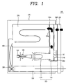
- FIG. 1 is a view schematically illustrating a dryer 100 having a waste heat recovery means 130 according to a first embodiment of the present disclosure
- FIG. 2 is a side view illustrating an internal structure of the first embodiment
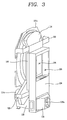
- FIG. 3 is a perspective view illustrating a rear surface side of a drum 104 in the first embodiment.
- a dryer 100 of the first embodiment may include a cabinet 102 having a substantially rectangular parallelepiped shape, and a drum 104 for putting the laundry which is a drying object thereinto is rotatably mounted within the cabinet 102.
- An air supply opening 104a configured to supply hot air for drying the laundry, and the supplied hot air is passed through an inner portion of the drum and exhausted to a lint filter installation unit 106 connected to a lower end of the front surface portion.
- a lint filter (not shown) for collecting foreign substances such as lint or the like separated from the laundry is mounted within the lint filter installation unit 106, and also formed with a flow path (or a passage) for moving the exhausted hot air.
- a funnel 112 for collecting hot air generated by a gas heater which will be described later is provided at a lower portion of the drum 104, and an end portion of the funnel 112 is connected to a back duct 114.
- the back duct 114 is located on a rear surface of the drum 104, and performs the role of transferring hot air discharged from the funnel 112 to the air supply opening 104a of the drum 104, and the funnel 112 and the back duct 114 function as an intake duct 110 for guiding the air existing within the cabinet into the drum. Furthermore, a funnel insertion port 114c into which an end portion of the funnel is inserted is formed on the back duct 114.
- An inner diameter of the funnel insertion port 114c is greater than an outer diameter of the funnel 112, and therefore, it is configured such that air within the cabinet can be inhaled into the back duct 114 through a gap between an outer circumferential portion of the funnel 112 and an inner circumferential portion of the funnel insertion port 114c.
- the intake duct 110 may include the funnel 112 and the back duct 114, but may not be necessarily limited to this, and an example in which the both are formed in an integral manner or a separate duct is additionally provided therein may be taken into consideration. Furthermore, an exhaust portion 114a of the back duct 114 is disposed to face the air supply opening 104a.
- a blower fan 108 for causing the flow of air is provided at the exhaust side of the lint filter installation unit 106, and an exhaust duct 120 for discharging air exhausted from the drum 104 to an outside of the cabinet 102 is provided at a rear side of the blower fan 108.
- a gas heater is located on a front surface of the funnel 112.
- the gas heater may include a gas nozzle 122 for spraying gas and a mixing pipe 124 for mixing gas sprayed from the gas nozzle and air.
- a supporting bracket 126 for supporting the gas nozzle 122 and mixing pipe 124 is provided on a bottom surface of the cabinet 102.
- a waste heat recovery means 130 for collecting heat energy is located on a rear surface of the drum 104.
- the waste heat recovery means 130 may be located out of the cabinet as illustrated in the drawing, or disposed to be accommodated within the cabinet 102.
- the waste heat recovery means 130 inhales and heats ambient air and then supplies the air to the back duct 114, and thus the ambient air is heated while passing through the waste heat recovery means 130, and moves along the ambient air duct 140 disposed between the back duct 114 and the waste heat recovery means 130.
- the ambient air duct 140 is formed such that ambient air inhaled through the surrounding area of an upper end portion thereof move along a lower side thereof.
- the ambient air duct 140 is communicated with the intake duct 110 between the drum 104 and heater.
- the ambient air duct 140 is communicated with the back duct 114.
- an ambient air outlet port 142 formed to face an ambient air inlet port 114b formed at the back duct 114 is disposed at a lower end portion of the ambient air duct 140. Accordingly, the heated ambient air is inhaled into the back duct 114 through the ambient air outlet port 142 and then mixed with hot air discharged from the funnel 112 and supplied to the drum 104.
- the waste heat recovery means 130 may include a pulsating heat pipe (PHP) 132 (refer to FIG. 4 ) and a casing 134 into which the PHP 132 is accommodated.
- the casing 134 has an extended rectangular parallelepiped shape, and is fixed within the cabinet 102 by a fixed bracket 150.
- An expansion pipe portion 136 having a substantially rectangular shaped cross-section communicated with the exhaust duct is disposed at a lower portion of the casing 134, and the expansion pipe portion 136 has a larger cross-sectional area compared to that of the exhaust duct 120. Through this, air exhausted from the exhaust duct 120 can be brought into contact with a PHP 132 provided within the casing 134 on a broader area.
- An exhaust port 136a is provided on one lateral surface of the expansion pipe portion 136, and air is exhausted to an outside of the cabinet 102 through the exhaust port 136a.
- An ambient air inhalation port 138 for inhaling ambient air is formed at an upper portion of the casing 134.
- the ambient air inhalation port 138 has an area capable of exposing all the condenser unit of the PHP 132 which will be described later, and aligned with respect to an ambient air inlet port 144 provided in the ambient air duct 140. Accordingly, ambient air is inhaled to the ambient air duct 140 through the ambient air inhalation port 138 and ambient air inlet port 144, and heated while being brought into contact with the PHP 132 during the process.
- the back duct 114 and the ambient air duct 140 comprise communication ports 114b, 142 disposed to face each other, respectively, and the communication ports are disposed at a location lower than that of the ambient air inlet inhalation port 138.
- the back duct 114 is mounted on a rear supporter 104b supporting a rear surface of the drum 104, and an upper end portion thereof has a fan shape to minimize flow resistance applied to hot air flowing into the drum 104. Furthermore, the back duct 114, the ambient air duct 140 and casing 134 are fixed in a state of being brought into contact with each other. Due to this, heat energy transferred from the back duct 114 can be transferred to ambient air passing through the ambient air duct 140, thereby minimizing thermal loss from the back duct 114.
- a plurality of the PHPs 132 are disposed according to the flow direction of air being exhausted.
- the plurality of PHPs 132 are disposed within the casing 134 to be extended in a vertical direction.
- the PHP 132 has a tube shape in which a heat transfer medium is sealed, and is disposed to form total three columns as illustrated in FIG. 5 .
- it may not be necessarily limited to three columns, and may be also disposed to form one or any number of columns.
- each PHP 132 may be alternately disposed to each other to allow the exhausted hot air or inhaled ambient air to be brought into contact with a large number of PHPs as far as possible.
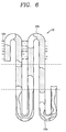
- the PHP 132 may include an evaporation unit 132a located within the expansion pipe portion and a condenser unit 132b exposed through the ambient air inhalation port 138.
- the evaporation unit 132a absorbs heat energy contained in the exhausted air to evaporate the heat transfer medium sealed therein.
- the evaporated heat transfer medium rises up and moves to the condenser unit 132b, and condenses while transferring heat to ambient air and moves again to the evaporation unit 132a.
- a plurality of fins 132c are formed in the condenser unit 132b, but such fins are not formed in the evaporation unit 132a.
- the PHPs 132 is formed with the plurality of fins 132c for expanding their surface area on a portion corresponding to the condenser unit 132b.
- the fins 132c are not formed on at least part of a portion corresponding to the evaporator of the PHPs 132.
- a small amount of lint or foreign substances may be contained in the exhausted air, and thus when fins are formed in the evaporation unit 132a, the lint or the like may be caught in the fins to obstruct the flow of air and heat transfer.
- the fins 132c may be also formed in the evaporation unit 132a, and in this case a spacing between fins may be formed to be greater than in the condenser unit 132b.
- the PHP 132 transports latent heat contained in working fluid due to the vibration of working fluid generated between the evaporation unit 132a and condenser unit 132b to transfer heat. Accordingly, there is no wick for flowing liquid that has been condensed in the condenser unit 132b back to the evaporation unit 132a, thereby resulting in a simple structure and allowing various types of fabrication.
- the PHP 132 may have a tube shape as illustrated in the drawing, and also have an internally partitioned flat tube shape.
- air moves along the intake duct 110 and exhaust duct 120 by a blower fan 108.
- the air within the cabinet 102 inhaled into the intake duct 110, particularly the funnel 112, is heated by the gas heater 122, 124 to have temperatures at about 700-800 °C.
- the hot air is inhaled into the back duct 114, and mixed with air within the cabinet 102 inhaled through a gap between the funnel insertion port 114c and the funnel 112, and cooled within a predetermined temperature range.
- ambient air is also inhaled to the waste heat recovery means 130 by the blower fan 108.
- the inhaled ambient air is heated while passing through the condenser unit 132b, and moved along the ambient air duct 140 and then supplied to the back duct 114.
- the hot and ambient air are mixed within the back duct 114, and as a result, hot air having a temperature of approximately 250 °C is supplied into the drum 104.
- air at normal temperature should be mixed with the hot air to cool the air to a suitable temperature since the temperature of the hot air is high as described above.
- the air being supplied for cooling has a temperature higher than a normal temperature, thereby reducing the amount of gas supplied to the gas heater.
- the supplied ambient air is supplied through an additional flow path (or an additional passage) separated from the intake duct 110 and then mixed, and therefore, it does not affect the intake duct 110 even when foreign substances are accumulated in the condenser unit 132b, thereby constantly maintaining the drying performance even if used for a long period of time.
- the funnel insertion port 114c and an outer circumferential portion of the funnel 112 are separated from each other, but an inner circumferential surface of the funnel insertion port 114c' may be brought into contact with an outer circumferential surface of the funnel 112 as illustrated in the second embodiment of FIG. 7 .
- the cooling of the hot air is entirely carried out by ambient air, thereby further reducing the amount of used gas.
- the present disclosure may not be necessarily limited to a case where the gas heater is used, and may be also applicable to a case where an electric heater is used.
- an example in which an electric heater 122' is provided in the intake duct 110 without using the gas heater may be also taken into consideration.
- the temperature of the generated hot air can be freely adjusted, and thus the cooling of hot air as in the gas heater is not required.
- an inner circumferential surface of the funnel insertion port 114c' is brought into contact with an outer circumferential surface of the funnel 112.
- ambient air heated by a waste heat recovery means 130 has a temperature lower than that of the electric heater 122' and thus the temperature of hot air mixed in the back duct 114 is lower than that of hot air immediately subsequent to passing through the electric heater 122'. Accordingly, the temperature of hot air that has passed through the electric heater 122' is set to be higher than 250 °C which is a temperature of hot air supplied to the drum 104.
- a heat pump may be provided at the same time.
- a condenser of the heat pump may be provided at a front end of the intake duct 110 to heat air in advance and then selectively heat the air using the electric heater 122'.
- the heated ambient air may flow between the condenser and the electric heater or flow to a downstream side of the heater.
Description
- The present invention relates to a dryer with a waste heat recovery means, and more particularly, to a dryer having a means for recovering and reusing heat energy contained in air exhausted from the dryer.
- Document
DE-A-10 2011 078 922 discloses a dryer comprising the features of the preamble ofclaim 1, comprising the waste heat recovery means to transfer heat from the air outlet to the air inlet leading into the laundry drum. - Document
CA-A-2 753 072 discloses a closest dryer operating on different sources of power or fuel, including a first heater (e. g. electric) and a second heater (e. g. combustional fuel). - In general, a laundry treating apparatus having a drying function such as a washer or dryer is a device for putting the laundry in a state that washing is completed and the dehydration process is finished into the drum, and supplying hot air into the drum to evaporate the moisture of the laundry and dry the laundry.
- For an example of a dryer, the aforementioned dryer may include a drum rotatably provided within the body to put the laundry thereinto, a drive motor configured to drive the drum, a blower fan configured to blow air into the drum, and a heating means configured to heat the air flowing into the drum. Furthermore, the heating means may use electrical resistance heat at high temperature generated using an electrical resistance or the heat of combustion generated by burning gas.
- On the other hand, air coming out of the drum may contain the moisture of the laundry within the drum, thus becoming air under a medium temperature and humidity condition. Here, a dryer can be classified according to a method of treating the medium temperature and humid air, and divided into a condensation type (circulation type) dryer for cooling air below its dew-point temperature through the condenser while circulating the medium temperature and humid air without being exhausted to the outside to condensate moisture contained in the medium temperature and humid air, and an exhaustion type dryer for allowing the medium temperature and humid air to be directly exhausted and wasted to the outside.
- In case of the condensation type dryer, in order to condensate air exhausted from the drum, the air should be subject to the process of cooling below the dew-point temperature and heated through the heating means prior to being supplied to the drum. Here, a loss of heat energy contained in the air may be generated while being cooled during the condensation process, and an additional heater or the like may be needed to heat the air to a temperature required for drying.
- In case of the exhaustion type dryer, it may be required to exhaust the medium temperature and humid air to the outside and inhale ambient air to heat the air to a temperature level required for drying through a heating means. In particular, high temperature air being exhausted to the outside contains heat energy transferred by the heating means, but it is exhausted and wasted to the outside, thereby reducing the heat efficiency.
- Accordingly, in recent years, laundry treating apparatuses for collecting energy required to generate hot air and energy being exhausted to the outside without being used have been introduced to increase energy efficiency, and a laundry treating apparatus having a heat pump system has been introduced as an example of the laundry treating apparatus. The heat pump system may include two heat exchangers, a compressor and an expansion apparatus, and energy contained in the exhausted hot air is recovered and reused in heating up air being supplied to the drum, thereby increasing energy efficiency.
- Specifically, in the heat pump system, an evaporator is provided at the exhaust side, and a condenser at an inlet side of the drum, and thus thermal energy is transferred to refrigerant through the evaporator and then thermal energy contained in the refrigerant is transferred to air flowing into the drum through the condenser, thereby generating hot air using waste energy. Here, a heater for reheating air that has been heated up while passing through the evaporator may be additionally provided therein.
- However, the heat pump system should be additionally provided with a compressor, an expansion apparatus, and the like in addition to two heat exchangers, and thus there is a restriction in the installation, and there is a problem in which additional power for driving the compressor is consumed. As an alternative of the heat pump system, there exists also an example of using a heat pipe. The heat pipe can transfer heat at the high temperature side to the low temperature side while sealed refrigerant repeats evaporation and condensation with no additional power source, and has a simple structure compared to the heat pump system and thus has an advantage of easy installation.
- An example of a dryer using the heat pipe has been disclosed in Korean Patent Application No.
10-2003-0038388 - The present disclosure is contrived to overcome the foregoing drawbacks in the related art, and a technical task of the present disclosure is to provide a dryer having a waste heat recovery means capable of minimizing a change of drying performance even when used for a long period of time.
- In order to accomplish the foregoing technical task, there is provided a dryer according to
claim 1. - Heat energy in the air being exhausted is collected using a waste heat recovery means to heat ambient air, and the heated ambient air is supplied to a downstream side of the heater, namely, between the drum and heater, and mixed with hot air generated by the heater and then supplied to the drum. Accordingly, ambient air other than air within the cabinet is inhaled into the waste heat recovery means, thereby minimizing blockage due to lint or foreign substances even when used for a long period of time.
- Here, the waste heat recovery means may be disposed at a rear side of the drum. According to circumstances, the waste heat recovery means may be mounted on a rear surface of the cabinet.
- Furthermore, the waste heat recovery means may include one or a plurality of pulsating heat pipes (PHPs) sealed with the heat transfer medium; and a casing in which the PHP is fixed therewithin. Of course, a typical heat pipe may be used instead of the PHP. In addition, the intake duct may include a back duct located on a rear surface of the drum, and the ambient air duct is disposed between the casing and the back duct.
- Here, the casing may include an ambient air inlet port for inhaling ambient air, and ambient air that has passed through the ambient air inlet port may flow into the ambient air duct.
- Furthermore, the back duct and the ambient air duct may include a communication ports disposed to face each other, respectively, and the communication ports may be disposed at a location lower than that of the ambient air inlet port.
- On the other hand, a plurality of the PHPs may be disposed according to the flow direction of air being exhausted. Here, a plurality of the PHPs may be alternately disposed to each other.
- On the other hand, at least some of the PHPs may be formed with a plurality of fins for expanding their surface area on a portion corresponding to the condenser unit. Here, the fin may not be formed on at least part of a portion corresponding to the evaporator of the PHPs.
- The waste heat recovery means may include one or a plurality of pulsating heat pipes (PHPs) sealed with the heat transfer medium; and a casing in which the PHP is fixed therewithin. Furthermore, the casing may include an ambient air inlet port for inhaling ambient air, and ambient air that has passed through the ambient air inlet port may flow into the ambient air duct. Here, the ambient air inlet port may be located at an upper portion than a communication position between the ambient air duct and the back duct.
- On the other hand, a funnel insertion port into which an end portion of the funnel is inserted may be formed at the back duct, and an inner diameter of the funnel insertion port may be formed to be greater than an outer diameter of the funnel. On the contrary, a funnel insertion port into which an end portion of the funnel is inserted may be formed at the back duct, and a funnel may be inserted thereinto such that an inner circumferential surface of the funnel insertion port is closely adhered to an outer circumferential surface of the funnel.
- The ambient air may be inhaled through an additional flow path independent from the hot air, and then mixed with hot air.
- Heat energy in the air being exhausted is recovered using a waste heat recovery means to heat ambient air, and the heated ambient air is supplied to a downstream side of the heater, namely, between the drum and heater, and mixed with hot air generated by the heater and then supplied to the drum. Accordingly, ambient air other than air within the cabinet is inhaled into the waste heat recovery means, thereby minimizing a change of flow resistance within the intake duct even when used for a long period of time.
- Furthermore, the waste heat recovery means may be disposed on a rear surface of the drum and thus easily installed within the cabinet, and the rear surface of the drum may be insulated, thereby further increasing the energy efficiency. In other words, the rear surface of the drum may be typically disposed adjacent to a rear surface of the cabinet to cause a large loss of heat energy through the rear surface, but a waste heat recovery means may be disposed on a rear surface of the drum and thus heat being leaked can be reused to heat ambient air.
- Furthermore, a PHP may be used as a waste heat recovery means, and thus can be produced at a lower cost than that of the heat pipe. Typically, in case of a PHP, its performance may vary according to the installation direction, but according to the foregoing aspect of the present disclosure, the PHP may be disposed in a vertical direction of the cabinet to exhibit the performance of the PHP to the maximum, thereby obtaining a heat transfer performance substantially similar to that of the heat pipe at a lower cost.
- Furthermore, an ambient air duct may be disposed between a back duct and a casing of the waste heat recovery means, thereby minimizing a heat loss that can be caused while heated ambient air passes through the ambient air duct.
- Furthermore, a fin may be provided in a condenser unit of the PHP to further enhance the heat transfer performance, and the fin may not be provided in an evaporation unit, thereby minimizing a reduction of heat transfer performance or an increase of flow resistance.
- Hot air at high temperature generated by a gas type heater may be cooled to a suitable level using ambient air heated by the waste heat recovery means, thereby reducing the gas consumption amount compared to when the ambient air is cooled using air at low temperature within the cabinet in the related art.
- The accompanying drawings, which are included to provide a further understanding of the invention and are incorporated in and constitute a part of this specification, illustrate embodiments of the invention and together with the description serve to explain the principles of the invention.
- In the drawings:
-
FIG. 1 is a view schematically illustrating a dryer having a waste heat recovery means according to a first embodiment of the present disclosure; -
FIG. 2 is a side view illustrating an internal structure of the first embodiment; -
FIG. 3 is a perspective view illustrating a rear surface side of a drum in the first embodiment; -
FIG. 4 is a perspective view illustrating a waste heat recovery means provided in the first embodiment; -
FIG. 5 is a cross-sectional view along line A-A' inFIG. 4 ; -
FIG. 6 is an enlarged cross-sectional view illustrating a pulsating heat pipe (PHP) provided inFIG. 1 ; -
FIG. 7 is a view schematically illustrating a dryer having a waste heat recovery means according to a second embodiment of the present disclosure; and -
FIG. 8 is a view schematically illustrating a dryer having a waste heat recovery means according to a third embodiment of the present disclosure. - Hereinafter, a dryer having a waste heat recovery means according to the present disclosure will be described in detail with reference to the accompanying drawings.
-
FIG. 1 is a view schematically illustrating adryer 100 having a waste heat recovery means 130 according to a first embodiment of the present disclosure, andFIG. 2 is a side view illustrating an internal structure of the first embodiment; andFIG. 3 is a perspective view illustrating a rear surface side of adrum 104 in the first embodiment. Referring toFIGS. 1 through 3 , adryer 100 of the first embodiment may include acabinet 102 having a substantially rectangular parallelepiped shape, and adrum 104 for putting the laundry which is a drying object thereinto is rotatably mounted within thecabinet 102. - An
air supply opening 104a configured to supply hot air for drying the laundry, and the supplied hot air is passed through an inner portion of the drum and exhausted to a lintfilter installation unit 106 connected to a lower end of the front surface portion. A lint filter (not shown) for collecting foreign substances such as lint or the like separated from the laundry is mounted within the lintfilter installation unit 106, and also formed with a flow path (or a passage) for moving the exhausted hot air. - Here, a
funnel 112 for collecting hot air generated by a gas heater which will be described later is provided at a lower portion of thedrum 104, and an end portion of thefunnel 112 is connected to aback duct 114. - The
back duct 114 is located on a rear surface of thedrum 104, and performs the role of transferring hot air discharged from thefunnel 112 to theair supply opening 104a of thedrum 104, and thefunnel 112 and theback duct 114 function as anintake duct 110 for guiding the air existing within the cabinet into the drum. Furthermore, afunnel insertion port 114c into which an end portion of the funnel is inserted is formed on theback duct 114. An inner diameter of thefunnel insertion port 114c is greater than an outer diameter of thefunnel 112, and therefore, it is configured such that air within the cabinet can be inhaled into theback duct 114 through a gap between an outer circumferential portion of thefunnel 112 and an inner circumferential portion of thefunnel insertion port 114c. - Here, the
intake duct 110 may include thefunnel 112 and theback duct 114, but may not be necessarily limited to this, and an example in which the both are formed in an integral manner or a separate duct is additionally provided therein may be taken into consideration. Furthermore, anexhaust portion 114a of theback duct 114 is disposed to face theair supply opening 104a. - On the other hand, a
blower fan 108 for causing the flow of air is provided at the exhaust side of the lintfilter installation unit 106, and anexhaust duct 120 for discharging air exhausted from thedrum 104 to an outside of thecabinet 102 is provided at a rear side of theblower fan 108. - Furthermore, a gas heater is located on a front surface of the
funnel 112. The gas heater may include agas nozzle 122 for spraying gas and a mixingpipe 124 for mixing gas sprayed from the gas nozzle and air. Referring toFIG. 2 , a supportingbracket 126 for supporting thegas nozzle 122 and mixingpipe 124 is provided on a bottom surface of thecabinet 102. - When gas supplied through a gas pipe which is not shown is sprayed through the
gas nozzle 122 and ignition is made, and flame is generated from the mixingpipe 124 into thefunnel 112. Due to this, air within thecabinet 102 inhaled through thefunnel 112 is heated by the flame and inhaled into thedrum 104 through theback duct 114. - On the other hand, air exhausted through the
exhaust duct 120 contains higher temperature and humidity compared to the air around thecabinet 102, and thus has more heat energy. A waste heat recovery means 130 for collecting heat energy is located on a rear surface of thedrum 104. Here, the waste heat recovery means 130 may be located out of the cabinet as illustrated in the drawing, or disposed to be accommodated within thecabinet 102. - The waste heat recovery means 130 inhales and heats ambient air and then supplies the air to the
back duct 114, and thus the ambient air is heated while passing through the waste heat recovery means 130, and moves along theambient air duct 140 disposed between theback duct 114 and the waste heat recovery means 130. Theambient air duct 140 is formed such that ambient air inhaled through the surrounding area of an upper end portion thereof move along a lower side thereof. - The
ambient air duct 140 is communicated with theintake duct 110 between thedrum 104 and heater. For example, theambient air duct 140 is communicated with theback duct 114. - On the other hand, an ambient
air outlet port 142 formed to face an ambientair inlet port 114b formed at theback duct 114 is disposed at a lower end portion of theambient air duct 140. Accordingly, the heated ambient air is inhaled into theback duct 114 through the ambientair outlet port 142 and then mixed with hot air discharged from thefunnel 112 and supplied to thedrum 104. - Specifically, the waste heat recovery means 130 may include a pulsating heat pipe (PHP) 132 (refer to
FIG. 4 ) and acasing 134 into which thePHP 132 is accommodated. Thecasing 134 has an extended rectangular parallelepiped shape, and is fixed within thecabinet 102 by a fixedbracket 150. Anexpansion pipe portion 136 having a substantially rectangular shaped cross-section communicated with the exhaust duct is disposed at a lower portion of thecasing 134, and theexpansion pipe portion 136 has a larger cross-sectional area compared to that of theexhaust duct 120. Through this, air exhausted from theexhaust duct 120 can be brought into contact with aPHP 132 provided within thecasing 134 on a broader area. Anexhaust port 136a is provided on one lateral surface of theexpansion pipe portion 136, and air is exhausted to an outside of thecabinet 102 through theexhaust port 136a. - An ambient
air inhalation port 138 for inhaling ambient air is formed at an upper portion of thecasing 134. The ambientair inhalation port 138 has an area capable of exposing all the condenser unit of thePHP 132 which will be described later, and aligned with respect to an ambientair inlet port 144 provided in theambient air duct 140. Accordingly, ambient air is inhaled to theambient air duct 140 through the ambientair inhalation port 138 and ambientair inlet port 144, and heated while being brought into contact with thePHP 132 during the process. - The
back duct 114 and theambient air duct 140 comprisecommunication ports inlet inhalation port 138. - The
back duct 114 is mounted on arear supporter 104b supporting a rear surface of thedrum 104, and an upper end portion thereof has a fan shape to minimize flow resistance applied to hot air flowing into thedrum 104. Furthermore, theback duct 114, theambient air duct 140 andcasing 134 are fixed in a state of being brought into contact with each other. Due to this, heat energy transferred from theback duct 114 can be transferred to ambient air passing through theambient air duct 140, thereby minimizing thermal loss from theback duct 114. - Referring to
FIG. 4 , a plurality of thePHPs 132 are disposed according to the flow direction of air being exhausted. For example, the plurality ofPHPs 132 are disposed within thecasing 134 to be extended in a vertical direction. ThePHP 132 has a tube shape in which a heat transfer medium is sealed, and is disposed to form total three columns as illustrated inFIG. 5 . Of course, it may not be necessarily limited to three columns, and may be also disposed to form one or any number of columns. - On the other hand, the each
PHP 132 may be alternately disposed to each other to allow the exhausted hot air or inhaled ambient air to be brought into contact with a large number of PHPs as far as possible. - Referring to
FIG. 6 , thePHP 132 may include anevaporation unit 132a located within the expansion pipe portion and acondenser unit 132b exposed through the ambientair inhalation port 138. Theevaporation unit 132a absorbs heat energy contained in the exhausted air to evaporate the heat transfer medium sealed therein. The evaporated heat transfer medium rises up and moves to thecondenser unit 132b, and condenses while transferring heat to ambient air and moves again to theevaporation unit 132a. Here, in order to enhance heat transfer efficiency, a plurality offins 132c are formed in thecondenser unit 132b, but such fins are not formed in theevaporation unit 132a. - In detail, at least some of the
PHPs 132 is formed with the plurality offins 132c for expanding their surface area on a portion corresponding to thecondenser unit 132b. Thefins 132c are not formed on at least part of a portion corresponding to the evaporator of thePHPs 132. - A small amount of lint or foreign substances may be contained in the exhausted air, and thus when fins are formed in the
evaporation unit 132a, the lint or the like may be caught in the fins to obstruct the flow of air and heat transfer. However, according to circumstances, thefins 132c may be also formed in theevaporation unit 132a, and in this case a spacing between fins may be formed to be greater than in thecondenser unit 132b. - The
PHP 132 transports latent heat contained in working fluid due to the vibration of working fluid generated between theevaporation unit 132a andcondenser unit 132b to transfer heat. Accordingly, there is no wick for flowing liquid that has been condensed in thecondenser unit 132b back to theevaporation unit 132a, thereby resulting in a simple structure and allowing various types of fabrication. Here, thePHP 132 may have a tube shape as illustrated in the drawing, and also have an internally partitioned flat tube shape. - Hereinafter, the operation of the first embodiment will be described.
- During the drying process, air moves along the
intake duct 110 andexhaust duct 120 by ablower fan 108. The air within thecabinet 102 inhaled into theintake duct 110, particularly thefunnel 112, is heated by thegas heater back duct 114, and mixed with air within thecabinet 102 inhaled through a gap between thefunnel insertion port 114c and thefunnel 112, and cooled within a predetermined temperature range. On the other hand, ambient air is also inhaled to the waste heat recovery means 130 by theblower fan 108. The inhaled ambient air is heated while passing through thecondenser unit 132b, and moved along theambient air duct 140 and then supplied to theback duct 114. - Accordingly, the hot and ambient air are mixed within the
back duct 114, and as a result, hot air having a temperature of approximately 250 °C is supplied into thedrum 104. When a gas heater is used, air at normal temperature should be mixed with the hot air to cool the air to a suitable temperature since the temperature of the hot air is high as described above. According to the foregoing embodiment, the air being supplied for cooling has a temperature higher than a normal temperature, thereby reducing the amount of gas supplied to the gas heater. - Furthermore, the supplied ambient air is supplied through an additional flow path (or an additional passage) separated from the
intake duct 110 and then mixed, and therefore, it does not affect theintake duct 110 even when foreign substances are accumulated in thecondenser unit 132b, thereby constantly maintaining the drying performance even if used for a long period of time. - On the other hand, according to the first embodiment, the
funnel insertion port 114c and an outer circumferential portion of thefunnel 112 are separated from each other, but an inner circumferential surface of thefunnel insertion port 114c' may be brought into contact with an outer circumferential surface of thefunnel 112 as illustrated in the second embodiment ofFIG. 7 . In this case, the cooling of the hot air is entirely carried out by ambient air, thereby further reducing the amount of used gas. - Furthermore, the present disclosure may not be necessarily limited to a case where the gas heater is used, and may be also applicable to a case where an electric heater is used. In other words, as illustrated in
FIG. 8 , an example in which an electric heater 122' is provided in theintake duct 110 without using the gas heater may be also taken into consideration. Here, in case of an electric heater 122', the temperature of the generated hot air can be freely adjusted, and thus the cooling of hot air as in the gas heater is not required. Accordingly, as illustrated in the second embodiment, an inner circumferential surface of thefunnel insertion port 114c' is brought into contact with an outer circumferential surface of thefunnel 112. - Here, ambient air heated by a waste heat recovery means 130 has a temperature lower than that of the electric heater 122' and thus the temperature of hot air mixed in the
back duct 114 is lower than that of hot air immediately subsequent to passing through the electric heater 122'. Accordingly, the temperature of hot air that has passed through the electric heater 122' is set to be higher than 250 °C which is a temperature of hot air supplied to thedrum 104. - On the other hand, when an electric heater 122' is used, a heat pump may be provided at the same time. In other words, a condenser of the heat pump may be provided at a front end of the
intake duct 110 to heat air in advance and then selectively heat the air using the electric heater 122'. In this case, the heated ambient air may flow between the condenser and the electric heater or flow to a downstream side of the heater. - The configurations and methods according to the above-described embodiments will not be applicable in a limited way to the foregoing dryer, and all or part of each embodiment may be selectively combined and configured to make various modifications thereto.
Claims (10)
- A dryer (100) having a waste heat recovery means (130), the dryer (100) comprising:a cabinet (102);a drum (104) rotatably mounted within the cabinet (102);an intake duct (110) configured to form an intake flow path for flowing air into the drum (104);an exhaust duct (120) configured to exhaust air out of the cabinet (102) from the drum (104);a heater (122, 124; 122') configured to heat air flowing into the drum (104);an ambient air duct (140) configured to inhale air outside the cabinet (102) and supply the air into the drum (104); anda waste heat recovery means (130) comprising an evaporation unit (132a) configured to absorb the heat of air being exhausted from the drum (104), a condenser unit (132b) configured to transfer heat absorbed from the evaporation unit (132a) to ambient air inhaled by the waste heat recovery means (130) and flowing into the ambient air duct (140), and a heat transfer medium configured to transfer heat between the evaporation unit (132a) and condenser unit (132b),characterized in that the ambient air duct (140) is connected with the intake duct (110) between the drum (104) and the heater (122, 124; 122') such that air heated by the heater (122, 124; 122') mixed with the ambient air heated by the condenser unit (132b) can be supplied into the drum (104).
- The dryer of claim 1, wherein the waste heat recovery means (130) is disposed at a rear side of the drum (104).
- The dryer of claim 1 or 2, wherein the waste heat recovery means (130) comprises:one or a plurality of pulsating heat pipes (PHPs) (132) in which the heat transfer medium is sealed; anda casing (134) in which the PHP (132) is fixed therewithin.
- The dryer of claim 3, wherein the intake duct (110) comprises a back duct (114) located on a rear surface of the drum (104), and the ambient air duct (140) is disposed between the casing (134) and the back duct (114).
- The dryer of claim 4, wherein the casing (134) comprises an ambient air inhalation port (138) for inhaling ambient air, and ambient air that has passed through the ambient air inhalation port (138) flows into the ambient air duct (140).
- The dryer of claim 5, wherein the back duct (114) and the ambient air duct (140) comprise communication ports (114b, 142) disposed to face each other, respectively, and the communication ports are disposed at a location lower than that of the ambient air inhalation port (138).
- The dryer of any of the claims 3 to 6, wherein a plurality of the PHPs (132) are disposed according to the flow direction of air being exhausted.
- The dryer of claim 7, wherein a plurality of the PHPs (132) are alternately disposed to each other.
- The dryer of any one of the claims 3 to 8, wherein at least some of the PHPs (132) is formed with a plurality of fins (132c) for expanding their surface area on a portion corresponding to the condenser unit (132b).
- The dryer of claim 9, wherein the fins are not formed on at least part of a portion corresponding to the evaporator of the PHPs (132).
Applications Claiming Priority (1)
| Application Number | Priority Date | Filing Date | Title |
|---|---|---|---|
| KR1020130071177A KR102063765B1 (en) | 2013-06-20 | 2013-06-20 | Dryer with a waste heat recovery means |
Publications (2)
| Publication Number | Publication Date |
|---|---|
| EP2816152A1 EP2816152A1 (en) | 2014-12-24 |
| EP2816152B1 true EP2816152B1 (en) | 2016-08-17 |
Family
ID=50972554
Family Applications (1)
| Application Number | Title | Priority Date | Filing Date |
|---|---|---|---|
| EP14172999.6A Not-in-force EP2816152B1 (en) | 2013-06-20 | 2014-06-18 | Dryer with a waste heat recovery means |
Country Status (4)
| Country | Link |
|---|---|
| US (1) | US9441322B2 (en) |
| EP (1) | EP2816152B1 (en) |
| KR (1) | KR102063765B1 (en) |
| CN (1) | CN104233733B (en) |
Families Citing this family (6)
| Publication number | Priority date | Publication date | Assignee | Title |
|---|---|---|---|---|
| KR102063765B1 (en) * | 2013-06-20 | 2020-03-02 | 엘지전자 주식회사 | Dryer with a waste heat recovery means |
| WO2015078526A1 (en) * | 2013-11-29 | 2015-06-04 | Arcelik Anonim Sirketi | Laundry treatment appliance with a compressor cooling line in parallel with processing air line |
| CN104859292B (en) * | 2015-05-07 | 2017-12-12 | 北京印刷学院 | A kind of intaglio printing press drying system |
| US10087569B2 (en) * | 2016-08-10 | 2018-10-02 | Whirlpool Corporation | Maintenance free dryer having multiple self-cleaning lint filters |
| CN107142654A (en) * | 2017-06-29 | 2017-09-08 | 东莞市皓奇企业管理服务有限公司 | The application method of intelligent power saving squeezing type washing machine |
| KR200496723Y1 (en) * | 2020-12-24 | 2023-04-11 | 주식회사 한국가스기술공사 | Gas heater for antifreezing drain pipe |
Family Cites Families (22)
| Publication number | Priority date | Publication date | Assignee | Title |
|---|---|---|---|---|
| US4112590A (en) * | 1975-07-02 | 1978-09-12 | August Lepper, Maschinen- Und Apparatebau Gmbh | Combined drum washer and drying arrangement |
| DE3481214D1 (en) * | 1983-09-22 | 1990-03-08 | Buehler Ag Geb | TEMPERATURE MACHINE. |
| US4603489A (en) * | 1984-10-05 | 1986-08-05 | Michael Goldberg | Heat pump closed loop drying |
| JP3719971B2 (en) | 2001-11-06 | 2005-11-24 | 株式会社椿本チエイン | Silent chain with wear-resistant coating |
| JP4169529B2 (en) * | 2002-04-23 | 2008-10-22 | 三洋電機株式会社 | Dry cleaning device |
| US20050086832A1 (en) * | 2003-10-28 | 2005-04-28 | Michel Declos | Air heater |
| JP4108072B2 (en) * | 2004-09-07 | 2008-06-25 | 三洋電機株式会社 | Dryer |
| DE102005023258A1 (en) * | 2004-11-16 | 2006-11-23 | Fan Separator Gmbh | Rotary drum for aerobic heating of free-flowing solids |
| EP1819869B1 (en) * | 2004-12-06 | 2014-06-11 | LG Electronics Inc. | Clothes dryer |
| US20080113609A1 (en) * | 2006-11-14 | 2008-05-15 | Robertshaw Controls Company | Combined Supply and Exhaust Apparatus |
| GB0701144D0 (en) * | 2007-01-22 | 2007-02-28 | Newman Peter | Domestic, outside, all-weather air clothes drying device |
| DE102007052079A1 (en) * | 2007-10-31 | 2009-05-07 | BSH Bosch und Siemens Hausgeräte GmbH | Exhaust air dryer with heat recovery and condensate tray and process for its operation |
| DE102008010519A1 (en) * | 2008-02-22 | 2009-09-03 | BSH Bosch und Siemens Hausgeräte GmbH | Dryer with cooled engine |
| DE102008054104A1 (en) * | 2008-10-31 | 2010-05-06 | Herbert Kannegiesser Gmbh | Method and device for treating the exhaust air from heated laundry machines |
| NL2003076C2 (en) * | 2009-06-23 | 2010-12-27 | Andries Koops | WASHER DRYER. |
| KR101130408B1 (en) * | 2009-10-07 | 2012-03-27 | 엘지전자 주식회사 | Clothes treating apparatus with wasted heat regeneration means |
| US20110302802A1 (en) * | 2010-06-09 | 2011-12-15 | General Electric Company | Dual fuel dryer |
| US8353114B2 (en) * | 2010-07-26 | 2013-01-15 | General Electric Company | Apparatus and method for refrigeration cycle with auxiliary heating |
| DE102011078922A1 (en) * | 2011-07-11 | 2013-01-17 | BSH Bosch und Siemens Hausgeräte GmbH | Exhaust air drying with additional heating and heat exchanger unit |
| CA2753072A1 (en) * | 2011-09-22 | 2013-03-22 | General Electric Company | Dual fuel dryer |
| CH705546A3 (en) * | 2013-01-23 | 2014-03-31 | V Zug Ag | Tumble dryer with additional heater and additional heat exchanger. |
| KR102063765B1 (en) * | 2013-06-20 | 2020-03-02 | 엘지전자 주식회사 | Dryer with a waste heat recovery means |
-
2013
- 2013-06-20 KR KR1020130071177A patent/KR102063765B1/en active IP Right Grant
-
2014
- 2014-06-18 EP EP14172999.6A patent/EP2816152B1/en not_active Not-in-force
- 2014-06-20 CN CN201410280864.3A patent/CN104233733B/en not_active Expired - Fee Related
- 2014-06-20 US US14/310,532 patent/US9441322B2/en active Active
Also Published As
| Publication number | Publication date |
|---|---|
| US20140373379A1 (en) | 2014-12-25 |
| EP2816152A1 (en) | 2014-12-24 |
| CN104233733B (en) | 2016-12-07 |
| CN104233733A (en) | 2014-12-24 |
| US9441322B2 (en) | 2016-09-13 |
| KR102063765B1 (en) | 2020-03-02 |
| KR20140147601A (en) | 2014-12-30 |
Similar Documents
| Publication | Publication Date | Title |
|---|---|---|
| EP2816152B1 (en) | Dryer with a waste heat recovery means | |
| US9207015B2 (en) | Dryer having evaporator equipped with second condenser | |
| EP2725133B1 (en) | Clothes dryer | |
| US9803312B2 (en) | Dryer with heat pump | |
| AU2012314534B2 (en) | Laundry treatment apparatus with heat pump | |
| KR101919887B1 (en) | A clothes dryer | |
| KR100925738B1 (en) | Temperature and humidity controlling apparatus of dryer | |
| US8418377B2 (en) | Dryer with heat pump | |
| CN104711833B (en) | Dryer | |
| CN107923114A (en) | drier | |
| EP3483515A1 (en) | Dehumidifier system | |
| KR101961141B1 (en) | Dryer with heat pump | |
| EP3149237B1 (en) | Laundry treatment appliance with a condensate water lint disintegration unit | |
| RU2012132715A (en) | HOUSEHOLD ELECTRICAL APPLIANCE | |
| KR101130408B1 (en) | Clothes treating apparatus with wasted heat regeneration means | |
| KR101176087B1 (en) | Dryer | |
| CN106245266A (en) | Clothes dryer systems and there is its dryer, washing-drying integral machine | |
| KR200391171Y1 (en) | Waste gas heat recovery device generating hot air and water | |
| KR20090116108A (en) | Dryer | |
| KR101241914B1 (en) | Dryer | |
| CN114059331A (en) | Condenser and clothes treatment equipment |
Legal Events
| Date | Code | Title | Description |
|---|---|---|---|
| PUAI | Public reference made under article 153(3) epc to a published international application that has entered the european phase |
Free format text: ORIGINAL CODE: 0009012 |
|
| 17P | Request for examination filed |
Effective date: 20140618 |
|
| AK | Designated contracting states |
Kind code of ref document: A1 Designated state(s): AL AT BE BG CH CY CZ DE DK EE ES FI FR GB GR HR HU IE IS IT LI LT LU LV MC MK MT NL NO PL PT RO RS SE SI SK SM TR |
|
| AX | Request for extension of the european patent |
Extension state: BA ME |
|
| R17P | Request for examination filed (corrected) |
Effective date: 20150511 |
|
| RBV | Designated contracting states (corrected) |
Designated state(s): AL AT BE BG CH CY CZ DE DK EE ES FI FR GB GR HR HU IE IS IT LI LT LU LV MC MK MT NL NO PL PT RO RS SE SI SK SM TR |
|
| GRAP | Despatch of communication of intention to grant a patent |
Free format text: ORIGINAL CODE: EPIDOSNIGR1 |
|
| INTG | Intention to grant announced |
Effective date: 20160303 |
|
| RAP1 | Party data changed (applicant data changed or rights of an application transferred) |
Owner name: LG ELECTRONICS INC. |
|
| GRAS | Grant fee paid |
Free format text: ORIGINAL CODE: EPIDOSNIGR3 |
|
| GRAA | (expected) grant |
Free format text: ORIGINAL CODE: 0009210 |
|
| RAP1 | Party data changed (applicant data changed or rights of an application transferred) |
Owner name: LG ELECTRONICS INC. |
|
| AK | Designated contracting states |
Kind code of ref document: B1 Designated state(s): AL AT BE BG CH CY CZ DE DK EE ES FI FR GB GR HR HU IE IS IT LI LT LU LV MC MK MT NL NO PL PT RO RS SE SI SK SM TR |
|
| REG | Reference to a national code |
Ref country code: GB Ref legal event code: FG4D |
|
| REG | Reference to a national code |
Ref country code: CH Ref legal event code: EP |
|
| REG | Reference to a national code |
Ref country code: IE Ref legal event code: FG4D |
|
| REG | Reference to a national code |
Ref country code: AT Ref legal event code: REF Ref document number: 821214 Country of ref document: AT Kind code of ref document: T Effective date: 20160915 |
|
| REG | Reference to a national code |
Ref country code: DE Ref legal event code: R096 Ref document number: 602014003059 Country of ref document: DE |
|
| REG | Reference to a national code |
Ref country code: NL Ref legal event code: MP Effective date: 20160817 |
|
| REG | Reference to a national code |
Ref country code: LT Ref legal event code: MG4D |
|
| REG | Reference to a national code |
Ref country code: AT Ref legal event code: MK05 Ref document number: 821214 Country of ref document: AT Kind code of ref document: T Effective date: 20160817 |
|
| PG25 | Lapsed in a contracting state [announced via postgrant information from national office to epo] |
Ref country code: NO Free format text: LAPSE BECAUSE OF FAILURE TO SUBMIT A TRANSLATION OF THE DESCRIPTION OR TO PAY THE FEE WITHIN THE PRESCRIBED TIME-LIMIT Effective date: 20161117 Ref country code: LT Free format text: LAPSE BECAUSE OF FAILURE TO SUBMIT A TRANSLATION OF THE DESCRIPTION OR TO PAY THE FEE WITHIN THE PRESCRIBED TIME-LIMIT Effective date: 20160817 Ref country code: NL Free format text: LAPSE BECAUSE OF FAILURE TO SUBMIT A TRANSLATION OF THE DESCRIPTION OR TO PAY THE FEE WITHIN THE PRESCRIBED TIME-LIMIT Effective date: 20160817 Ref country code: RS Free format text: LAPSE BECAUSE OF FAILURE TO SUBMIT A TRANSLATION OF THE DESCRIPTION OR TO PAY THE FEE WITHIN THE PRESCRIBED TIME-LIMIT Effective date: 20160817 Ref country code: HR Free format text: LAPSE BECAUSE OF FAILURE TO SUBMIT A TRANSLATION OF THE DESCRIPTION OR TO PAY THE FEE WITHIN THE PRESCRIBED TIME-LIMIT Effective date: 20160817 Ref country code: FI Free format text: LAPSE BECAUSE OF FAILURE TO SUBMIT A TRANSLATION OF THE DESCRIPTION OR TO PAY THE FEE WITHIN THE PRESCRIBED TIME-LIMIT Effective date: 20160817 Ref country code: IT Free format text: LAPSE BECAUSE OF FAILURE TO SUBMIT A TRANSLATION OF THE DESCRIPTION OR TO PAY THE FEE WITHIN THE PRESCRIBED TIME-LIMIT Effective date: 20160817 |
|
| PG25 | Lapsed in a contracting state [announced via postgrant information from national office to epo] |
Ref country code: LV Free format text: LAPSE BECAUSE OF FAILURE TO SUBMIT A TRANSLATION OF THE DESCRIPTION OR TO PAY THE FEE WITHIN THE PRESCRIBED TIME-LIMIT Effective date: 20160817 Ref country code: AT Free format text: LAPSE BECAUSE OF FAILURE TO SUBMIT A TRANSLATION OF THE DESCRIPTION OR TO PAY THE FEE WITHIN THE PRESCRIBED TIME-LIMIT Effective date: 20160817 Ref country code: PT Free format text: LAPSE BECAUSE OF FAILURE TO SUBMIT A TRANSLATION OF THE DESCRIPTION OR TO PAY THE FEE WITHIN THE PRESCRIBED TIME-LIMIT Effective date: 20161219 Ref country code: ES Free format text: LAPSE BECAUSE OF FAILURE TO SUBMIT A TRANSLATION OF THE DESCRIPTION OR TO PAY THE FEE WITHIN THE PRESCRIBED TIME-LIMIT Effective date: 20160817 Ref country code: GR Free format text: LAPSE BECAUSE OF FAILURE TO SUBMIT A TRANSLATION OF THE DESCRIPTION OR TO PAY THE FEE WITHIN THE PRESCRIBED TIME-LIMIT Effective date: 20161118 Ref country code: PL Free format text: LAPSE BECAUSE OF FAILURE TO SUBMIT A TRANSLATION OF THE DESCRIPTION OR TO PAY THE FEE WITHIN THE PRESCRIBED TIME-LIMIT Effective date: 20160817 Ref country code: SE Free format text: LAPSE BECAUSE OF FAILURE TO SUBMIT A TRANSLATION OF THE DESCRIPTION OR TO PAY THE FEE WITHIN THE PRESCRIBED TIME-LIMIT Effective date: 20160817 |
|
| PG25 | Lapsed in a contracting state [announced via postgrant information from national office to epo] |
Ref country code: RO Free format text: LAPSE BECAUSE OF FAILURE TO SUBMIT A TRANSLATION OF THE DESCRIPTION OR TO PAY THE FEE WITHIN THE PRESCRIBED TIME-LIMIT Effective date: 20160817 Ref country code: EE Free format text: LAPSE BECAUSE OF FAILURE TO SUBMIT A TRANSLATION OF THE DESCRIPTION OR TO PAY THE FEE WITHIN THE PRESCRIBED TIME-LIMIT Effective date: 20160817 |
|
| REG | Reference to a national code |
Ref country code: FR Ref legal event code: PLFP Year of fee payment: 4 |
|
| REG | Reference to a national code |
Ref country code: DE Ref legal event code: R097 Ref document number: 602014003059 Country of ref document: DE |
|
| PG25 | Lapsed in a contracting state [announced via postgrant information from national office to epo] |
Ref country code: SM Free format text: LAPSE BECAUSE OF FAILURE TO SUBMIT A TRANSLATION OF THE DESCRIPTION OR TO PAY THE FEE WITHIN THE PRESCRIBED TIME-LIMIT Effective date: 20160817 Ref country code: DK Free format text: LAPSE BECAUSE OF FAILURE TO SUBMIT A TRANSLATION OF THE DESCRIPTION OR TO PAY THE FEE WITHIN THE PRESCRIBED TIME-LIMIT Effective date: 20160817 Ref country code: SK Free format text: LAPSE BECAUSE OF FAILURE TO SUBMIT A TRANSLATION OF THE DESCRIPTION OR TO PAY THE FEE WITHIN THE PRESCRIBED TIME-LIMIT Effective date: 20160817 Ref country code: BG Free format text: LAPSE BECAUSE OF FAILURE TO SUBMIT A TRANSLATION OF THE DESCRIPTION OR TO PAY THE FEE WITHIN THE PRESCRIBED TIME-LIMIT Effective date: 20161117 Ref country code: CZ Free format text: LAPSE BECAUSE OF FAILURE TO SUBMIT A TRANSLATION OF THE DESCRIPTION OR TO PAY THE FEE WITHIN THE PRESCRIBED TIME-LIMIT Effective date: 20160817 Ref country code: BE Free format text: LAPSE BECAUSE OF FAILURE TO SUBMIT A TRANSLATION OF THE DESCRIPTION OR TO PAY THE FEE WITHIN THE PRESCRIBED TIME-LIMIT Effective date: 20160817 |
|
| PLBE | No opposition filed within time limit |
Free format text: ORIGINAL CODE: 0009261 |
|
| STAA | Information on the status of an ep patent application or granted ep patent |
Free format text: STATUS: NO OPPOSITION FILED WITHIN TIME LIMIT |
|
| 26N | No opposition filed |
Effective date: 20170518 |
|
| PG25 | Lapsed in a contracting state [announced via postgrant information from national office to epo] |
Ref country code: SI Free format text: LAPSE BECAUSE OF FAILURE TO SUBMIT A TRANSLATION OF THE DESCRIPTION OR TO PAY THE FEE WITHIN THE PRESCRIBED TIME-LIMIT Effective date: 20160817 |
|
| PG25 | Lapsed in a contracting state [announced via postgrant information from national office to epo] |
Ref country code: MC Free format text: LAPSE BECAUSE OF FAILURE TO SUBMIT A TRANSLATION OF THE DESCRIPTION OR TO PAY THE FEE WITHIN THE PRESCRIBED TIME-LIMIT Effective date: 20160817 |
|
| REG | Reference to a national code |
Ref country code: CH Ref legal event code: PL |
|
| REG | Reference to a national code |
Ref country code: IE Ref legal event code: MM4A |
|
| PG25 | Lapsed in a contracting state [announced via postgrant information from national office to epo] |
Ref country code: CH Free format text: LAPSE BECAUSE OF NON-PAYMENT OF DUE FEES Effective date: 20170630 Ref country code: LU Free format text: LAPSE BECAUSE OF NON-PAYMENT OF DUE FEES Effective date: 20170618 Ref country code: LI Free format text: LAPSE BECAUSE OF NON-PAYMENT OF DUE FEES Effective date: 20170630 Ref country code: IE Free format text: LAPSE BECAUSE OF NON-PAYMENT OF DUE FEES Effective date: 20170618 |
|
| REG | Reference to a national code |
Ref country code: FR Ref legal event code: PLFP Year of fee payment: 5 |
|
| PG25 | Lapsed in a contracting state [announced via postgrant information from national office to epo] |
Ref country code: MT Free format text: LAPSE BECAUSE OF NON-PAYMENT OF DUE FEES Effective date: 20170618 |
|
| PG25 | Lapsed in a contracting state [announced via postgrant information from national office to epo] |
Ref country code: AL Free format text: LAPSE BECAUSE OF FAILURE TO SUBMIT A TRANSLATION OF THE DESCRIPTION OR TO PAY THE FEE WITHIN THE PRESCRIBED TIME-LIMIT Effective date: 20160817 |
|
| PGFP | Annual fee paid to national office [announced via postgrant information from national office to epo] |
Ref country code: GB Payment date: 20180504 Year of fee payment: 5 |
|
| PG25 | Lapsed in a contracting state [announced via postgrant information from national office to epo] |
Ref country code: HU Free format text: LAPSE BECAUSE OF FAILURE TO SUBMIT A TRANSLATION OF THE DESCRIPTION OR TO PAY THE FEE WITHIN THE PRESCRIBED TIME-LIMIT; INVALID AB INITIO Effective date: 20140618 |
|
| PG25 | Lapsed in a contracting state [announced via postgrant information from national office to epo] |
Ref country code: CY Free format text: LAPSE BECAUSE OF FAILURE TO SUBMIT A TRANSLATION OF THE DESCRIPTION OR TO PAY THE FEE WITHIN THE PRESCRIBED TIME-LIMIT Effective date: 20160817 |
|
| PG25 | Lapsed in a contracting state [announced via postgrant information from national office to epo] |
Ref country code: MK Free format text: LAPSE BECAUSE OF FAILURE TO SUBMIT A TRANSLATION OF THE DESCRIPTION OR TO PAY THE FEE WITHIN THE PRESCRIBED TIME-LIMIT Effective date: 20160817 |
|
| GBPC | Gb: european patent ceased through non-payment of renewal fee |
Effective date: 20190618 |
|
| PG25 | Lapsed in a contracting state [announced via postgrant information from national office to epo] |
Ref country code: TR Free format text: LAPSE BECAUSE OF FAILURE TO SUBMIT A TRANSLATION OF THE DESCRIPTION OR TO PAY THE FEE WITHIN THE PRESCRIBED TIME-LIMIT Effective date: 20160817 |
|
| PG25 | Lapsed in a contracting state [announced via postgrant information from national office to epo] |
Ref country code: GB Free format text: LAPSE BECAUSE OF NON-PAYMENT OF DUE FEES Effective date: 20190618 |
|
| PG25 | Lapsed in a contracting state [announced via postgrant information from national office to epo] |
Ref country code: IS Free format text: LAPSE BECAUSE OF FAILURE TO SUBMIT A TRANSLATION OF THE DESCRIPTION OR TO PAY THE FEE WITHIN THE PRESCRIBED TIME-LIMIT Effective date: 20161217 |
|
| PGFP | Annual fee paid to national office [announced via postgrant information from national office to epo] |
Ref country code: FR Payment date: 20200507 Year of fee payment: 7 Ref country code: DE Payment date: 20200506 Year of fee payment: 7 |
|
| REG | Reference to a national code |
Ref country code: DE Ref legal event code: R119 Ref document number: 602014003059 Country of ref document: DE |
|
| PG25 | Lapsed in a contracting state [announced via postgrant information from national office to epo] |
Ref country code: DE Free format text: LAPSE BECAUSE OF NON-PAYMENT OF DUE FEES Effective date: 20220101 |
|
| PG25 | Lapsed in a contracting state [announced via postgrant information from national office to epo] |
Ref country code: FR Free format text: LAPSE BECAUSE OF NON-PAYMENT OF DUE FEES Effective date: 20210630 |