EP2815975A1 - Evaporative system for removing water from an aircraft lavatory or galley floor - Google Patents
Evaporative system for removing water from an aircraft lavatory or galley floor Download PDFInfo
- Publication number
- EP2815975A1 EP2815975A1 EP14168356.5A EP14168356A EP2815975A1 EP 2815975 A1 EP2815975 A1 EP 2815975A1 EP 14168356 A EP14168356 A EP 14168356A EP 2815975 A1 EP2815975 A1 EP 2815975A1
- Authority
- EP
- European Patent Office
- Prior art keywords
- container
- water
- conduit
- floor structure
- edge
- Prior art date
- Legal status (The legal status is an assumption and is not a legal conclusion. Google has not performed a legal analysis and makes no representation as to the accuracy of the status listed.)
- Granted
Links
Images




Classifications
-
- C—CHEMISTRY; METALLURGY
- C02—TREATMENT OF WATER, WASTE WATER, SEWAGE, OR SLUDGE
- C02F—TREATMENT OF WATER, WASTE WATER, SEWAGE, OR SLUDGE
- C02F1/00—Treatment of water, waste water, or sewage
- C02F1/02—Treatment of water, waste water, or sewage by heating
- C02F1/04—Treatment of water, waste water, or sewage by heating by distillation or evaporation
- C02F1/10—Treatment of water, waste water, or sewage by heating by distillation or evaporation by direct contact with a particulate solid or with a fluid, as a heat transfer medium
-
- B—PERFORMING OPERATIONS; TRANSPORTING
- B64—AIRCRAFT; AVIATION; COSMONAUTICS
- B64D—EQUIPMENT FOR FITTING IN OR TO AIRCRAFT; FLIGHT SUITS; PARACHUTES; ARRANGEMENT OR MOUNTING OF POWER PLANTS OR PROPULSION TRANSMISSIONS IN AIRCRAFT
- B64D11/00—Passenger or crew accommodation; Flight-deck installations not otherwise provided for
- B64D11/02—Toilet fittings
-
- B—PERFORMING OPERATIONS; TRANSPORTING
- B01—PHYSICAL OR CHEMICAL PROCESSES OR APPARATUS IN GENERAL
- B01F—MIXING, e.g. DISSOLVING, EMULSIFYING OR DISPERSING
- B01F23/00—Mixing according to the phases to be mixed, e.g. dispersing or emulsifying
- B01F23/20—Mixing gases with liquids
- B01F23/23—Mixing gases with liquids by introducing gases into liquid media, e.g. for producing aerated liquids
-
- B—PERFORMING OPERATIONS; TRANSPORTING
- B64—AIRCRAFT; AVIATION; COSMONAUTICS
- B64D—EQUIPMENT FOR FITTING IN OR TO AIRCRAFT; FLIGHT SUITS; PARACHUTES; ARRANGEMENT OR MOUNTING OF POWER PLANTS OR PROPULSION TRANSMISSIONS IN AIRCRAFT
- B64D11/00—Passenger or crew accommodation; Flight-deck installations not otherwise provided for
- B64D11/04—Galleys
Definitions
- Embodiments of this disclosure relate generally to aircraft systems, and more particularly, to an evaporative system and method for removing gray water from an aircraft floor.
- Gray water is "used” water that drains from drinking water systems, from wash basins during hand washing, material poured down a galley sink, or any other instance in which water is soiled or loaded with waste (e.g., soaps, detergents, soils from hand washing). Gray water does not include contaminants such as toilet waste which is generally referred to as black water.
- gray water system and a waste water system for collecting, storing and ultimately disposing of gray water and black water.
- black water is vacuumed away to a waste tank on the aircraft, and gray water is vacuumed away to the same tank or discharged out of the airplane via specially designed and located drain masts made for that purpose.
- a mast drain extends from a fuselage of the aircraft to eject the gray water from the aircraft.
- the mast drain includes associated plumbing throughout the aircraft and may limit positioning of monuments, such as lavatories, within a cabin of the aircraft.
- monuments such as lavatories
- some aircraft may omit the mast drain and collect both grey water and black water in the on-board tank.
- the associated plumbing for channeling the grey water and black water to the tank may be difficult to tap into, depending on the position of the monuments. Accordingly, lavatories on such aircraft generally do not include floor drains.
- a system for removing gray water from a lavatory or galley area comprises: a floor having a first edge and a second edge, the floor slope downwardly towards the second edge; a container defined in the floor adjacent the second edge; a conduit in flow communication with the container, wherein the conduit provides an air flow to evaporate the gray water collected in the container.
- the system may further comprise a void area formed within the floor, the container positioned within the void area.
- the system may further comprise a water fixture positioned adjacent the void area.
- a gap may be area formed between the water fixture and the second edge of the floor, the gap being in communication with the container.
- the water fixture may be one of a commode, a sink, a drinking water supply or the like.
- the system may further comprise a screen positioned over the gap.
- the conduit may be coupled to a ventilation system, the ventilation system being configured to generate an air flow in the conduit to evaporate the gray water collected in the container.
- the conduit may be positioned within a wall of one of the lavatory or galley,
- the system may further comprise a heating device to warm the container.
- a system for removing gray water from a lavatory or galley area comprises: a container positioned in a floor of the lavatory or the galley; a conduit in flow communication with the container, wherein the conduit is coupled to a ventilation system configured to generate an air flow in the conduit to evaporate the gray water collected in the container.
- the floor may be sloped towards the container.
- the system may further comprise a void area formed within the floor, the container being positioned within the void area.
- the system may further comprise a water fixture positioned adjacent the void area, wherein a gap is formed between the water fixture and the floor, the gap allowing the gray water to flow into the gap and down to the container.
- the system may further comprise a screen positioned over the gap.
- the system may further comprise a heating device to warm the container.
- the conduit may be positioned within a wall of one of the lavatory or galley.
- a method for removing gray water from a lavatory comprises: sloping a floor from a first edge down to a second edge; positioning a container within the floor and adjacent the second edge; and directing an air flow from a ventilation system towards the container to evaporate the gray water within the container.
- the method may further comprise: forming a void area in the floor, the container positioned within the void area; and positioning a water fixture adjacent the void area, wherein a gap is formed between the water fixture and the second edge of the floor.
- the method may further comprise heating the container.
- the method may further comprise positioning a conduit in flow communication with the container, wherein the conduit is coupled to the ventilation system configured to generate an air flow in the conduit to evaporate the gray water collected in the container.
- an aircraft 100 is shown.
- a cabin area 101 of the aircraft 10 0 may have one or more galley areas 102.
- the galley areas 102 may be used by aircraft personnel to prepare and serve food, beverages and other items.
- the aircraft 100 may also have one or more lavatories 1
- the galley area 102 and lavatories 104 may produce gray water from sources such as galley sinks, lavatory sinks, drinking water systems, and the like.
- the galley area 102 and lavatories 104 may have other fixtures and/or devices that produce gray water.
- gray water may build up on the floor of the galley area 102 and lavatories 104 due to water spilling from the lavatory and/or galley sinks during hand washing, water spilling from a drinking water system, or any other instance.
- a system 200 for removing gray water that may build up on the floor structure 204 of the galley area 102 and or lavatories 104 is shown.
- the system 200 is implemented in a lavatory 104 of an aircraft 100 ( Figure 1 ).
- a void area 202 is area formed within the floor structure 204 .
- the void area 202 may be formed adjacent a water fixture 206 since the water fixture 206 may be the main source of the gray water that may build up on the floor structure 204 .
- the void area 202 is area formed partially around a commode 206A .
- the void area 202 may be formed around a sink 206B or in other areas in the floor structure 204 of the lavatory 104.
- the void area 202 may be area formed in different shapes and or sizes.
- the void area 202 may be used as a holding area for storing gray water that has built up on the floor structure 204 of the lavatory 1
- the void area 202 may be sized and shaped to accommodate a container 208,
- the container 208 may be positioned within the void area 202 and/or defined within the floor structure 204.
- the container 208 may be used to collect gray water and or other fluids that may collect on the floor structure 204 of the lavatory 104.
- the container 208 may also be sized and shaped for positioning within the void area 202.
- the container 208 is positioned around the commode 206A .
- the container 208 may be shaped to accommodate the piping associated with the installation of the commode 206A .
- the container may be "U" or "O" shaped and positioned partially or totally around a circumference of the commode 206A .
- the commode 206A is positioned adjacent the container 208 such that a gap 210 is area formed between the commode 206A and a top surface 204A of the floor structure 204 .
- the gap 210 acts as a floor drain to allow gray water to flow into the container 208 .
- a screen 212 may be positioned over the gap 210 . The screen 212 may be used to prevent objects other than the gray water from accumulating in the container 208.
- the container 208 may be positioned underneath the floor structure 204 of the lavatory 104 as shown in Figure 4 .
- one or more channels 214 may be formed through the floor structure 204.
- the channels 214 may be used to allow the gray water or other fluids on the top surface 204A of the floor structure 204 to flow to the container 208 .
- a screen 212 may be positioned over the channel 214 .
- the screen 212 may be used to prevent objects other than the gray water from accumulating in the container 208 .
- the top surface 204A of the floor structure 204 may be angled towards the gap 210 and/or channel 214 .
- the angle of the top surface 204A of the floor structure 204 should be sufficient to allow gray water or other fluids on the top surface 204A of the floor structure 204 to flow towards and into the gap 210 and or channel 214 such that the gray water or other fluids may be collected in the container 208 .
- the angle of the top surface 204A of the floor structure 204 should not be so steep as to make it uncomfortable and/or difficult for a person to stand.
- the top surface 204A of the floor structure 204 is angled from a first edge 205 to a second edge 207 wherein the second edge 207 is adjacent the gap 210 and/or channel 214 . Further, the container 208 and/or the void area 202 is defined or positioned adjacent the second edge 207 .
- the system 200 may use a conduit 216 to provide a means for ventilating the air around the container 208 .
- the conduit 216 may be positioned within a wall 209 of the lavatory 104 and attached to a ventilation system 218 of the aircraft 100 ( Figure 1 ).
- a conduit like structure may also be formed as an integral part of the lavatory 1
- the conduit 216 may be coupled to an existing ventilation system 218 in the lavatory 104 of the aircraft 1
- the ventilation system 218 may allow air flow to evaporate and transport the moist air out of the container 208 and hence the lavatory 104.
- the ventilation system 218 is always turned on during a flight thereby allowing for continuous evaporation and transport of gray water which may accumulate in the container 208.
- a heating device 220 may be used to heat the container 208.
- the heating device 220 may be used to increase the evaporation rate of the gray water in the container 208 .
- the ventilation system 218 may still be used to allow air flow to further evaporate and transport the moist air out of the container 208 and hence the lavatory 104.
- the heating device 220 may be warm enough to increase the evaporation rate but not warm enough to be a fire hazard.
- the system 200 is shown in a galley area 102 of an aircraft 100 ( Figure 1 ).
- the galley area 102 may have multiple water fixtures 206.
- the galley area 102 may have a sink 206B, a drinking water system 206C or the like,
- Other fixture 206 may be in the galley area 102 without departing from the spirit and scope.
- the system 200 in the galley area 102 is similar to that in the lavatory 104.
- a void area 202 may be formed within the floor structure 204.
- the void area 202 may be formed adjacent the fixture 206.
- the void area 202 is formed adjacent the sink 206B and drinking water system 206C.
- the void area 202 may be formed adjacent a sink 206B or in other areas in the floor structure 204 of the galley area 102.
- the void area 202 may be formed in different shapes and or sizes.
- the void area 202 may be used as a holding area for storing gray water that has built up on the floor structure 204 of the galley 102.
- the void area 202 may be sized and shaped to accommodate a container 208.
- the container 208 may be positioned within the void area 202 and/or defined in the floor structure 204.
- the container 208 may be used to collect gray water and or other fluids that may collect on the floor structure 2 4 of the galley area 102.
- the container 208 may also be sized and shaped to accommodate for positioning within the void area 202.
- the container 208 is positioned adjacent the sink 206B and drinking water system 206C .
- the container 208 may be shaped to accommodate the piping associated with the installation of the sink 206B and drinking water system 206C .
- cabinetry 222 supporting the sink 206B is positioned adjacent the container 208 such that a gap 210 is formed between the cabinetry 2 2 2 and a top surface 204A of the floor structure 204 .
- the gap 210 acts as a floor drain to allow gray water to flow into the container 208 .
- a screen 212 may be positioned over the gap 210 . The screen 212 may be used to prevent objects other than the gray water from accumulating in the container 208.
- the container 208 may be positioned underneath the floor structure 204 of the galley area 102 as shown in Figure 7 .
- one or more channels 214 may be formed through the floor structure 204 .
- the channels 214 may be used to allow the gray water or other fluids on the top surface 204A of the floor structure 204 to flow to the container 208.
- a screen 212 may be positioned over the channel 214 .
- the screen 212 may be used to prevent objects other than the gray water from accumulating in the container 208 .
- the top surface 204A of the floor structure 204 may be angled towards the gap 210 and/or channel 214 .
- the angle of the top surface 204A of the floor structure 204 should be sufficient to allow gray water or other fluids on the top surface 204A of the floor structure 204 to flow towards and into the gap 210 and or channel 214 such that the gray water or other fluids may be collected in the container 208 .
- the angle of the top surface 204A of the floor structure 204 should not be so steep as to make it uncomfortable and or difficult for a person to stand.
- the top surface 204A of the floor structure 204 is angled from a first edge 205 to a second edge 207 wherein the second edge 207 is adjacent the gap 210 and/or channel 214 . Further, the container 208 and/or the void area 202 is defined or positioned adjacent the second edge 207 .
- the system 200 may use a conduit 216 positioned within a wall 209 of the galley 102 to provide a means for ventilating the air around the container 208.
- a conduit like structure may also be formed as an integral part of the galley 102.
- the conduit 216 may be attached to a ventilation system 218 of the aircraft 100.
- the conduit 216 may be coupled to an existing ventilation system 218 in the galley area 102 of the aircraft 1
- the ventilation system 218 may allow air flow to evaporate and transport of the moist air out of the container 208 and hence the galley area 102.
- the ventilation system 218 is always turned on during a flight thereby allowing for continuous evaporation and transport of gray water which may accumulate in the container 208.
- a heating device 220 may be used to heat The container 208 .
- the heating device 220 may be used to increase the evaporation rate of the gray water in the container 208.
- the ventilation system 218 may still be used to allow air flow to further evaporate and transport the moist air out of the container 208 and hence the galley area 102.
Landscapes
- Engineering & Computer Science (AREA)
- Aviation & Aerospace Engineering (AREA)
- Chemical & Material Sciences (AREA)
- Environmental & Geological Engineering (AREA)
- Life Sciences & Earth Sciences (AREA)
- Hydrology & Water Resources (AREA)
- Thermal Sciences (AREA)
- Water Supply & Treatment (AREA)
- Physics & Mathematics (AREA)
- Organic Chemistry (AREA)
- Chemical Kinetics & Catalysis (AREA)
- Sink And Installation For Waste Water (AREA)
- Building Environments (AREA)
Abstract
Description
- Embodiments of this disclosure relate generally to aircraft systems, and more particularly, to an evaporative system and method for removing gray water from an aircraft floor.
- In most commercial aircraft, waste water and material tend to accrue during the flight. The waste water often includes leftover portions of beverages served to the passengers, water from the lavatory, and so forth. One form of waste water is gray water. Gray water is "used" water that drains from drinking water systems, from wash basins during hand washing, material poured down a galley sink, or any other instance in which water is soiled or loaded with waste (e.g., soaps, detergents, soils from hand washing). Gray water does not include contaminants such as toilet waste which is generally referred to as black water.
- Most commercial aircraft may be equipped with a gray water system and a waste water system for collecting, storing and ultimately disposing of gray water and black water. For example, in some aircraft, black water is vacuumed away to a waste tank on the aircraft, and gray water is vacuumed away to the same tank or discharged out of the airplane via specially designed and located drain masts made for that purpose.
- In the case where the gray water is discharged outside the aircraft, a mast drain extends from a fuselage of the aircraft to eject the gray water from the aircraft. However, the mast drain includes associated plumbing throughout the aircraft and may limit positioning of monuments, such as lavatories, within a cabin of the aircraft. As such, some aircraft may omit the mast drain and collect both grey water and black water in the on-board tank. However, the associated plumbing for channeling the grey water and black water to the tank may be difficult to tap into, depending on the position of the monuments. Accordingly, lavatories on such aircraft generally do not include floor drains.
- Therefore, it Would be desirable to provide a system and method that overcomes the above.
- According to one aspect of the present invention, a system for removing gray water from a lavatory or galley area comprises: a floor having a first edge and a second edge, the floor slope downwardly towards the second edge; a container defined in the floor adjacent the second edge; a conduit in flow communication with the container, wherein the conduit provides an air flow to evaporate the gray water collected in the container.
- The system may further comprise a void area formed within the floor, the container positioned within the void area.
- The system may further comprise a water fixture positioned adjacent the void area.
- A gap may be area formed between the water fixture and the second edge of the floor, the gap being in communication with the container.
- The water fixture may be one of a commode, a sink, a drinking water supply or the like.
- The system may further comprise a screen positioned over the gap.
- The conduit may be coupled to a ventilation system, the ventilation system being configured to generate an air flow in the conduit to evaporate the gray water collected in the container.
- The conduit may be positioned within a wall of one of the lavatory or galley,
- The system may further comprise a heating device to warm the container.
- According to a further aspect of the present invention, a system for removing gray water from a lavatory or galley area comprises: a container positioned in a floor of the lavatory or the galley; a conduit in flow communication with the container, wherein the conduit is coupled to a ventilation system configured to generate an air flow in the conduit to evaporate the gray water collected in the container.
- The floor may be sloped towards the container.
- The system may further comprise a void area formed within the floor, the container being positioned within the void area.
- The system may further comprise a water fixture positioned adjacent the void area, wherein a gap is formed between the water fixture and the floor, the gap allowing the gray water to flow into the gap and down to the container.
- The system may further comprise a screen positioned over the gap.
- The system may further comprise a heating device to warm the container.
- The conduit may be positioned within a wall of one of the lavatory or galley.
- According to a further aspect of the present invention, a method for removing gray water from a lavatory comprises: sloping a floor from a first edge down to a second edge; positioning a container within the floor and adjacent the second edge; and directing an air flow from a ventilation system towards the container to evaporate the gray water within the container.
- The method may further comprise: forming a void area in the floor, the container positioned within the void area; and positioning a water fixture adjacent the void area, wherein a gap is formed between the water fixture and the second edge of the floor.
- The method may further comprise heating the container.
- The method may further comprise positioning a conduit in flow communication with the container, wherein the conduit is coupled to the ventilation system configured to generate an air flow in the conduit to evaporate the gray water collected in the container.
- The features, functions, and advantages may be achieved independently in various embodiments of the disclosure or may be combined in yet other embodiments.
- Embodiments of the disclosure will become more fully understood from the detailed description and the accompanying drawings, wherein:
-
Figure 1 is a top view of an aircraft illustrating areas where the evaporative system for removing water may be installed; -
Figure 2 illustrates a lavatory area of the aircraft ofFigure 1 implementing the evaporative system for removing water; -
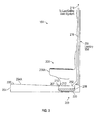
Figure 3 illustrates a cross-sectional view of the lavatory area ofFigure 2 implementing the evaporative system for removing water, -
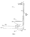
Figure 4 illustrates a cross-sectional view of the lavatory area ofFigure 2 implementing another embodiment of the evaporative system for removing water; -
Figure 5 illustrates a galley area of the aircraft ofFigure 1 implementing the evaporative system for removing water; -
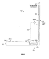
Figure 6 illustrates a cross-sectional view of the galley area ofFigure 5 implementing the evaporative system for removing water; and -
Figure 7 illustrates a cross-sectional view of the galley area ofFigure 5 implementing another embodiment of the evaporative system for removing water. - Referring now to
Figure 1 , anaircraft 100 is shown. In acabin area 101 of theaircraft 100 may have one ormore galley areas 102. Thegalley areas 102 may be used by aircraft personnel to prepare and serve food, beverages and other items. Theaircraft 100 may also have one ormore lavatories 1 Thegalley area 102 andlavatories 104 may produce gray water from sources such as galley sinks, lavatory sinks, drinking water systems, and the like. Thegalley area 102 andlavatories 104 may have other fixtures and/or devices that produce gray water. - Often, gray water may build up on the floor of the
galley area 102 andlavatories 104 due to water spilling from the lavatory and/or galley sinks during hand washing, water spilling from a drinking water system, or any other instance. In some aircraft, it may be difficult to install a floor drain in thegalley area 102 andlavatories 104 to remove gray water which may accumulate on the floor of thegalley area 102 and/orlavatories 104. This may be due to limited space for the associated plumbing for channeling the grey water, a lack of a drain mast in the aircraft or the like. - Referring now to
Figures 2-4 , asystem 200 for removing gray water that may build up on thefloor structure 204 of thegalley area 102 and orlavatories 104 is shown. As shown in the embodiment ofFigure 2-4 , thesystem 200 is implemented in alavatory 104 of an aircraft 100 (Figure 1 ). In the system 200 avoid area 202 is area formed within thefloor structure 204. Thevoid area 202 may be formed adjacent awater fixture 206 since thewater fixture 206 may be the main source of the gray water that may build up on thefloor structure 204. In the present embodiment, thevoid area 202 is area formed partially around acommode 206A. However, thevoid area 202 may be formed around asink 206B or in other areas in thefloor structure 204 of thelavatory 104. - The
void area 202 may be area formed in different shapes and or sizes. Thevoid area 202 may be used as a holding area for storing gray water that has built up on thefloor structure 204 of thelavatory 1 Alternatively, thevoid area 202 may be sized and shaped to accommodate acontainer 208, Thecontainer 208 may be positioned within thevoid area 202 and/or defined within thefloor structure 204. Thecontainer 208 may be used to collect gray water and or other fluids that may collect on thefloor structure 204 of thelavatory 104. - The
container 208 may also be sized and shaped for positioning within thevoid area 202. For example, in the present embodiment, thecontainer 208 is positioned around thecommode 206A. Thus, thecontainer 208 may be shaped to accommodate the piping associated with the installation of thecommode 206A. For example, the container may be "U" or "O" shaped and positioned partially or totally around a circumference of thecommode 206A. - In the present embodiment, the
commode 206A is positioned adjacent thecontainer 208 such that agap 210 is area formed between thecommode 206A and atop surface 204A of thefloor structure 204. Thegap 210 acts as a floor drain to allow gray water to flow into thecontainer 208. Ascreen 212 may be positioned over thegap 210. Thescreen 212 may be used to prevent objects other than the gray water from accumulating in thecontainer 208. - In accordance with another embodiment of the present invention, instead of forming the
void area 202 within thefloor structure 204, thecontainer 208 may be positioned underneath thefloor structure 204 of thelavatory 104 as shown inFigure 4 . In this embodiment, one ormore channels 214 may be formed through thefloor structure 204. Thechannels 214 may be used to allow the gray water or other fluids on thetop surface 204A of thefloor structure 204 to flow to thecontainer 208. As in the previous embodiment, ascreen 212 may be positioned over thechannel 214. Thescreen 212 may be used to prevent objects other than the gray water from accumulating in thecontainer 208. - To aid in the collection of the gray water and/or other fluids into the
container 208 thetop surface 204A of thefloor structure 204 may be angled towards thegap 210 and/orchannel 214. The angle of thetop surface 204A of thefloor structure 204 should be sufficient to allow gray water or other fluids on thetop surface 204A of thefloor structure 204 to flow towards and into thegap 210 and orchannel 214 such that the gray water or other fluids may be collected in thecontainer 208. However, the angle of thetop surface 204A of thefloor structure 204 should not be so steep as to make it uncomfortable and/or difficult for a person to stand. In the present embodiment, thetop surface 204A of thefloor structure 204 is angled from afirst edge 205 to asecond edge 207 wherein thesecond edge 207 is adjacent thegap 210 and/orchannel 214. Further, thecontainer 208 and/or thevoid area 202 is defined or positioned adjacent thesecond edge 207. - The
system 200 may use aconduit 216 to provide a means for ventilating the air around thecontainer 208. Theconduit 216 may be positioned within awall 209 of thelavatory 104 and attached to aventilation system 218 of the aircraft 100 (Figure 1 ). A conduit like structure may also be formed as an integral part of thelavatory 1 In the present embodiment, theconduit 216 may be coupled to an existingventilation system 218 in thelavatory 104 of theaircraft 1 Theventilation system 218 may allow air flow to evaporate and transport the moist air out of thecontainer 208 and hence thelavatory 104. In general, theventilation system 218 is always turned on during a flight thereby allowing for continuous evaporation and transport of gray water which may accumulate in thecontainer 208. - In accordance with one embodiment, a
heating device 220 may be used to heat thecontainer 208. Theheating device 220 may be used to increase the evaporation rate of the gray water in thecontainer 208. Theventilation system 218 may still be used to allow air flow to further evaporate and transport the moist air out of thecontainer 208 and hence thelavatory 104. Theheating device 220 may be warm enough to increase the evaporation rate but not warm enough to be a fire hazard. - Referring to
Figures 5-7 , thesystem 200 is shown in agalley area 102 of an aircraft 100 (Figure 1 ). Thegalley area 102 may havemultiple water fixtures 206. For example, thegalley area 102 may have asink 206B, adrinking water system 206C or the like,Other fixture 206 may be in thegalley area 102 without departing from the spirit and scope. - The
system 200 in thegalley area 102 is similar to that in thelavatory 104. Avoid area 202 may be formed within thefloor structure 204. Thevoid area 202 may be formed adjacent thefixture 206. In the present embodiment, thevoid area 202 is formed adjacent thesink 206B anddrinking water system 206C. However, thevoid area 202 may be formed adjacent asink 206B or in other areas in thefloor structure 204 of thegalley area 102. - The
void area 202 may be formed in different shapes and or sizes. Thevoid area 202 may be used as a holding area for storing gray water that has built up on thefloor structure 204 of thegalley 102. Alternatively, thevoid area 202 may be sized and shaped to accommodate acontainer 208. Thecontainer 208 may be positioned within thevoid area 202 and/or defined in thefloor structure 204. Thecontainer 208 may be used to collect gray water and or other fluids that may collect on the floor structure 2 4 of thegalley area 102. - The
container 208 may also be sized and shaped to accommodate for positioning within thevoid area 202. For example, in the present embodiment, thecontainer 208 is positioned adjacent thesink 206B anddrinking water system 206C. Thecontainer 208 may be shaped to accommodate the piping associated with the installation of thesink 206B anddrinking water system 206C. - In the present embodiment,
cabinetry 222 supporting thesink 206B is positioned adjacent thecontainer 208 such that agap 210 is formed between thecabinetry 222 and atop surface 204A of thefloor structure 204. Thegap 210 acts as a floor drain to allow gray water to flow into thecontainer 208. Ascreen 212 may be positioned over thegap 210. Thescreen 212 may be used to prevent objects other than the gray water from accumulating in thecontainer 208. - In accordance with another embodiment of the present invention, instead of forming the
void area 202 within thefloor structure 204, thecontainer 208 may be positioned underneath thefloor structure 204 of thegalley area 102 as shown inFigure 7 . In this embodiment, one ormore channels 214 may be formed through thefloor structure 204. Thechannels 214 may be used to allow the gray water or other fluids on thetop surface 204A of thefloor structure 204 to flow to thecontainer 208. As in the previous embodiment, ascreen 212 may be positioned over thechannel 214. Thescreen 212 may be used to prevent objects other than the gray water from accumulating in thecontainer 208. - To aid in the collection of the gray water and or other fluids into the
container 208 thetop surface 204A of thefloor structure 204 may be angled towards thegap 210 and/orchannel 214. The angle of thetop surface 204A of thefloor structure 204 should be sufficient to allow gray water or other fluids on thetop surface 204A of thefloor structure 204 to flow towards and into thegap 210 and orchannel 214 such that the gray water or other fluids may be collected in thecontainer 208. However, the angle of thetop surface 204A of thefloor structure 204 should not be so steep as to make it uncomfortable and or difficult for a person to stand. In the present embodiment, thetop surface 204A of thefloor structure 204 is angled from afirst edge 205 to asecond edge 207 wherein thesecond edge 207 is adjacent thegap 210 and/orchannel 214. Further, thecontainer 208 and/or thevoid area 202 is defined or positioned adjacent thesecond edge 207. - The
system 200 may use aconduit 216 positioned within awall 209 of thegalley 102 to provide a means for ventilating the air around thecontainer 208. A conduit like structure may also be formed as an integral part of thegalley 102. Theconduit 216 may be attached to aventilation system 218 of theaircraft 100. In the present embodiment, theconduit 216 may be coupled to an existingventilation system 218 in thegalley area 102 of theaircraft 1 Theventilation system 218 may allow air flow to evaporate and transport of the moist air out of thecontainer 208 and hence thegalley area 102. In general, theventilation system 218 is always turned on during a flight thereby allowing for continuous evaporation and transport of gray water which may accumulate in thecontainer 208. - In accordance with one embodiment, a
heating device 220 may be used to heat Thecontainer 208. Theheating device 220 may be used to increase the evaporation rate of the gray water in thecontainer 208. Theventilation system 218 may still be used to allow air flow to further evaporate and transport the moist air out of thecontainer 208 and hence thegalley area 102. - While embodiments of the disclosure have been described in terms of various specific embodiments, those skilled in the art will recognize that the embodiments of the disclosure may be practiced with modifications.
Claims (13)
- A system (200) for removing gray water from a lavatory (104) or a galley area (102), said system comprising:a floor structure (204) having a first edge (205) and a second edge (207), the floor structure sloped downwardly towards the second edge;a container (208) defined in the floor structure adjacent the second edge; anda conduit (216) in flow communication with the container, wherein the conduit provides an air flow to evaporate the gray water collected in the container.
- The system of Claim 1, further comprising a void area (202) formed within the floor structure (204), the container (208) positioned within the void area.
- The system of Claim 2, further comprising a water fixture (206) positioned adjacent the void area (202).
- The system of Claim 3, wherein a gap (210) is formed between the water fixture (206) and the second edge (207) of the floor structure (204), the gap in communication with the container (208).
- The system of Claim 3 or 4, wherein the water fixture (206) is one of a commode (206A), a sink (206B), a drinking water supply (206C), or the like.
- The system of Claim 4 or 5, further comprising a screen (212) positioned over the gap (210).
- The system of any preceding Claim, wherein the conduit (216) is coupled to a ventilation system (218), the ventilation system configured to generate the air flow in the conduit to evaporate the gray water collected in the container (208).
- The system of any preceding Claim, wherein the conduit (206) is positioned within a wall (209) of one of the lavatory (104) or the galley area (102).
- The system of any preceding Claim, further comprising a heating device (220) to warm the container (208).
- A method for removing gray water from a lavatory, said method comprising:sloping a floor structure (204) from a first edge (205) down to a second wedge (207);positioning a container (208) within the floor structure and adjacent the second edge; anddirecting an air flow from a ventilation system (218) towards the container to evaporate the gray water within the container.
- The method of Claim 10, further comprising:forming a void area (202) in the floor structure (204), the container (208) positioned within the void area; andpositioning a water fixture (206) adjacent the void area, wherein a gap (210) is formed between the water fixture and the second edge (207) of the floor.
- The method of Claim 10 or 11, further comprising heating the container (208) using a heating device (220).
- The method of any of Claims 10-12, further comprising positioning a conduit (216) in flow communication with the container (208), wherein the conduit is coupled to the ventilation system (218) configured to generate the air flow in the conduit to evaporate the gray water collected in the container.
Applications Claiming Priority (1)
| Application Number | Priority Date | Filing Date | Title |
|---|---|---|---|
| US13/906,062 US9022364B2 (en) | 2013-05-30 | 2013-05-30 | Evaporative system for removing water from an aircraft lavatory and or galley floor |
Publications (2)
| Publication Number | Publication Date |
|---|---|
| EP2815975A1 true EP2815975A1 (en) | 2014-12-24 |
| EP2815975B1 EP2815975B1 (en) | 2018-07-11 |
Family
ID=50693552
Family Applications (1)
| Application Number | Title | Priority Date | Filing Date |
|---|---|---|---|
| EP14168356.5A Active EP2815975B1 (en) | 2013-05-30 | 2014-05-14 | Evaporative system for removing water from an aircraft lavatory or galley floor |
Country Status (2)
| Country | Link |
|---|---|
| US (1) | US9022364B2 (en) |
| EP (1) | EP2815975B1 (en) |
Cited By (1)
| Publication number | Priority date | Publication date | Assignee | Title |
|---|---|---|---|---|
| DE102018002896A1 (en) * | 2018-04-09 | 2019-10-10 | Airbus Operations Gmbh | Floor exhaust system for an aircraft toilet |
Families Citing this family (3)
| Publication number | Priority date | Publication date | Assignee | Title |
|---|---|---|---|---|
| US10207807B2 (en) | 2016-04-13 | 2019-02-19 | The Boeing Company | Condensate removal system of an aircraft cooling system |
| US20210214066A1 (en) * | 2018-05-31 | 2021-07-15 | The Yokohama Rubber Co., Ltd. | Floor structure for aircraft lavatory unit |
| EP4001113B1 (en) * | 2020-11-18 | 2023-11-01 | The Boeing Company | Dry floor hardened grid |
Citations (4)
| Publication number | Priority date | Publication date | Assignee | Title |
|---|---|---|---|---|
| US2396992A (en) * | 1944-10-04 | 1946-03-19 | Evans Randolph | Bathroom unit |
| US5903937A (en) * | 1997-03-19 | 1999-05-18 | Amtech Corporation | Bathroom module accessible to wheeled assemblies |
| EP2148017A2 (en) * | 2008-07-24 | 2010-01-27 | Osoa Proiektuak, S.L. | Shower system accessible to people with reduced mobility, and associated piping |
| US20110258769A1 (en) * | 2008-10-02 | 2011-10-27 | Bombardier Inc. | Shower system for aircraft |
Family Cites Families (6)
| Publication number | Priority date | Publication date | Assignee | Title |
|---|---|---|---|---|
| US4165545A (en) | 1977-12-22 | 1979-08-28 | Stoltzfus Sarah D | Commode condensation/overflow catch basin |
| SE7909844L (en) | 1979-11-29 | 1981-05-30 | Electrolux Ab | SET AND DEVICE FOR KEEPING A FROZEN FREEZE |
| DE19720762C2 (en) | 1997-05-07 | 2001-10-31 | Berliner Stadtreinigungsbetr E | Sanitary cell with sanitary and technical room as well as procedures for cleaning and / or disinfecting the sanitary room |
| WO2004040680A2 (en) * | 2002-10-24 | 2004-05-13 | Airbus Deutschland Gmbh | Device for producing water on board of an airplane |
| WO2006004333A1 (en) | 2004-06-30 | 2006-01-12 | Gil Yong Lee | Movable temporary toilet |
| US7854852B1 (en) * | 2010-03-17 | 2010-12-21 | Richard Martin Reavis | In-drain device for the collection, extraction and diversion of gray water for reuse |
-
2013
- 2013-05-30 US US13/906,062 patent/US9022364B2/en active Active
-
2014
- 2014-05-14 EP EP14168356.5A patent/EP2815975B1/en active Active
Patent Citations (4)
| Publication number | Priority date | Publication date | Assignee | Title |
|---|---|---|---|---|
| US2396992A (en) * | 1944-10-04 | 1946-03-19 | Evans Randolph | Bathroom unit |
| US5903937A (en) * | 1997-03-19 | 1999-05-18 | Amtech Corporation | Bathroom module accessible to wheeled assemblies |
| EP2148017A2 (en) * | 2008-07-24 | 2010-01-27 | Osoa Proiektuak, S.L. | Shower system accessible to people with reduced mobility, and associated piping |
| US20110258769A1 (en) * | 2008-10-02 | 2011-10-27 | Bombardier Inc. | Shower system for aircraft |
Cited By (1)
| Publication number | Priority date | Publication date | Assignee | Title |
|---|---|---|---|---|
| DE102018002896A1 (en) * | 2018-04-09 | 2019-10-10 | Airbus Operations Gmbh | Floor exhaust system for an aircraft toilet |
Also Published As
| Publication number | Publication date |
|---|---|
| US20140353855A1 (en) | 2014-12-04 |
| US9022364B2 (en) | 2015-05-05 |
| EP2815975B1 (en) | 2018-07-11 |
Similar Documents
| Publication | Publication Date | Title |
|---|---|---|
| EP1901960B1 (en) | Gray water interface valve systems and methods | |
| EP2815975A1 (en) | Evaporative system for removing water from an aircraft lavatory or galley floor | |
| US8074933B2 (en) | Aircraft graywater ejection system | |
| CN103732493B (en) | There is the aircraft construction thing of sanitary module and galley module | |
| US9139996B2 (en) | Removable locking floor sink drain screen for enlarged opening | |
| US10266268B2 (en) | Integrated sink and disposal unit | |
| US20200217055A1 (en) | Liquid waste receptor | |
| US9958182B1 (en) | Humidifier auxiliary drain pan | |
| CN104220333B (en) | Compact galley tubing | |
| US10059454B2 (en) | Aircraft galley plumbing system | |
| US20170341602A1 (en) | Hand hygiene arrangement | |
| CN110712739A (en) | Dry floor liquid treatment system | |
| US20180112382A1 (en) | Lavatory for a vehicle as well as a vehicle having such a lavatory | |
| US8857481B2 (en) | Removable drain funnel | |
| EP3768594B1 (en) | Waste transfer unit | |
| US6763531B1 (en) | Method for the containment of fluids from an aircraft commode | |
| US20140345695A1 (en) | Grey water interface for high flow applications in vacuum systems | |
| RU110390U1 (en) | MOBILE PUBLIC TOILET | |
| CN108069032A (en) | Aircraft airborne drainage | |
| US11401703B1 (en) | Hand washing station for galley monument | |
| RU109069U1 (en) | SANITARY TECHNICAL EQUIPMENT OF TWO-STOREY PASSENGER CAR | |
| KR20160132795A (en) | Water closet for water saving system | |
| JP7674899B2 (en) | Floor Assembly and Method | |
| JP7830082B2 (en) | Dry floor hardening grid | |
| US20160145846A1 (en) | Toilet system for a lavatory of a vehicle, lavatory of a vehicle, and aircraft with such a lavatory |
Legal Events
| Date | Code | Title | Description |
|---|---|---|---|
| PUAI | Public reference made under article 153(3) epc to a published international application that has entered the european phase |
Free format text: ORIGINAL CODE: 0009012 |
|
| 17P | Request for examination filed |
Effective date: 20140514 |
|
| AK | Designated contracting states |
Kind code of ref document: A1 Designated state(s): AL AT BE BG CH CY CZ DE DK EE ES FI FR GB GR HR HU IE IS IT LI LT LU LV MC MK MT NL NO PL PT RO RS SE SI SK SM TR |
|
| AX | Request for extension of the european patent |
Extension state: BA ME |
|
| R17P | Request for examination filed (corrected) |
Effective date: 20150623 |
|
| RBV | Designated contracting states (corrected) |
Designated state(s): AL AT BE BG CH CY CZ DE DK EE ES FI FR GB GR HR HU IE IS IT LI LT LU LV MC MK MT NL NO PL PT RO RS SE SI SK SM TR |
|
| 17Q | First examination report despatched |
Effective date: 20160804 |
|
| STAA | Information on the status of an ep patent application or granted ep patent |
Free format text: STATUS: EXAMINATION IS IN PROGRESS |
|
| GRAP | Despatch of communication of intention to grant a patent |
Free format text: ORIGINAL CODE: EPIDOSNIGR1 |
|
| STAA | Information on the status of an ep patent application or granted ep patent |
Free format text: STATUS: GRANT OF PATENT IS INTENDED |
|
| INTG | Intention to grant announced |
Effective date: 20170614 |
|
| GRAJ | Information related to disapproval of communication of intention to grant by the applicant or resumption of examination proceedings by the epo deleted |
Free format text: ORIGINAL CODE: EPIDOSDIGR1 |
|
| STAA | Information on the status of an ep patent application or granted ep patent |
Free format text: STATUS: EXAMINATION IS IN PROGRESS |
|
| INTC | Intention to grant announced (deleted) | ||
| GRAP | Despatch of communication of intention to grant a patent |
Free format text: ORIGINAL CODE: EPIDOSNIGR1 |
|
| STAA | Information on the status of an ep patent application or granted ep patent |
Free format text: STATUS: GRANT OF PATENT IS INTENDED |
|
| INTG | Intention to grant announced |
Effective date: 20171122 |
|
| GRAS | Grant fee paid |
Free format text: ORIGINAL CODE: EPIDOSNIGR3 |
|
| GRAA | (expected) grant |
Free format text: ORIGINAL CODE: 0009210 |
|
| STAA | Information on the status of an ep patent application or granted ep patent |
Free format text: STATUS: THE PATENT HAS BEEN GRANTED |
|
| AK | Designated contracting states |
Kind code of ref document: B1 Designated state(s): AL AT BE BG CH CY CZ DE DK EE ES FI FR GB GR HR HU IE IS IT LI LT LU LV MC MK MT NL NO PL PT RO RS SE SI SK SM TR |
|
| REG | Reference to a national code |
Ref country code: GB Ref legal event code: FG4D |
|
| REG | Reference to a national code |
Ref country code: CH Ref legal event code: EP |
|
| REG | Reference to a national code |
Ref country code: AT Ref legal event code: REF Ref document number: 1016620 Country of ref document: AT Kind code of ref document: T Effective date: 20180715 |
|
| REG | Reference to a national code |
Ref country code: IE Ref legal event code: FG4D |
|
| REG | Reference to a national code |
Ref country code: DE Ref legal event code: R096 Ref document number: 602014028169 Country of ref document: DE |
|
| REG | Reference to a national code |
Ref country code: NL Ref legal event code: MP Effective date: 20180711 |
|
| REG | Reference to a national code |
Ref country code: LT Ref legal event code: MG4D |
|
| REG | Reference to a national code |
Ref country code: AT Ref legal event code: MK05 Ref document number: 1016620 Country of ref document: AT Kind code of ref document: T Effective date: 20180711 |
|
| PG25 | Lapsed in a contracting state [announced via postgrant information from national office to epo] |
Ref country code: NL Free format text: LAPSE BECAUSE OF FAILURE TO SUBMIT A TRANSLATION OF THE DESCRIPTION OR TO PAY THE FEE WITHIN THE PRESCRIBED TIME-LIMIT Effective date: 20180711 |
|
| PG25 | Lapsed in a contracting state [announced via postgrant information from national office to epo] |
Ref country code: LT Free format text: LAPSE BECAUSE OF FAILURE TO SUBMIT A TRANSLATION OF THE DESCRIPTION OR TO PAY THE FEE WITHIN THE PRESCRIBED TIME-LIMIT Effective date: 20180711 Ref country code: RS Free format text: LAPSE BECAUSE OF FAILURE TO SUBMIT A TRANSLATION OF THE DESCRIPTION OR TO PAY THE FEE WITHIN THE PRESCRIBED TIME-LIMIT Effective date: 20180711 Ref country code: IS Free format text: LAPSE BECAUSE OF FAILURE TO SUBMIT A TRANSLATION OF THE DESCRIPTION OR TO PAY THE FEE WITHIN THE PRESCRIBED TIME-LIMIT Effective date: 20181111 Ref country code: PL Free format text: LAPSE BECAUSE OF FAILURE TO SUBMIT A TRANSLATION OF THE DESCRIPTION OR TO PAY THE FEE WITHIN THE PRESCRIBED TIME-LIMIT Effective date: 20180711 Ref country code: AT Free format text: LAPSE BECAUSE OF FAILURE TO SUBMIT A TRANSLATION OF THE DESCRIPTION OR TO PAY THE FEE WITHIN THE PRESCRIBED TIME-LIMIT Effective date: 20180711 Ref country code: BG Free format text: LAPSE BECAUSE OF FAILURE TO SUBMIT A TRANSLATION OF THE DESCRIPTION OR TO PAY THE FEE WITHIN THE PRESCRIBED TIME-LIMIT Effective date: 20181011 Ref country code: NO Free format text: LAPSE BECAUSE OF FAILURE TO SUBMIT A TRANSLATION OF THE DESCRIPTION OR TO PAY THE FEE WITHIN THE PRESCRIBED TIME-LIMIT Effective date: 20181011 Ref country code: SE Free format text: LAPSE BECAUSE OF FAILURE TO SUBMIT A TRANSLATION OF THE DESCRIPTION OR TO PAY THE FEE WITHIN THE PRESCRIBED TIME-LIMIT Effective date: 20180711 Ref country code: GR Free format text: LAPSE BECAUSE OF FAILURE TO SUBMIT A TRANSLATION OF THE DESCRIPTION OR TO PAY THE FEE WITHIN THE PRESCRIBED TIME-LIMIT Effective date: 20181012 Ref country code: FI Free format text: LAPSE BECAUSE OF FAILURE TO SUBMIT A TRANSLATION OF THE DESCRIPTION OR TO PAY THE FEE WITHIN THE PRESCRIBED TIME-LIMIT Effective date: 20180711 |
|
| PG25 | Lapsed in a contracting state [announced via postgrant information from national office to epo] |
Ref country code: ES Free format text: LAPSE BECAUSE OF FAILURE TO SUBMIT A TRANSLATION OF THE DESCRIPTION OR TO PAY THE FEE WITHIN THE PRESCRIBED TIME-LIMIT Effective date: 20180711 Ref country code: AL Free format text: LAPSE BECAUSE OF FAILURE TO SUBMIT A TRANSLATION OF THE DESCRIPTION OR TO PAY THE FEE WITHIN THE PRESCRIBED TIME-LIMIT Effective date: 20180711 Ref country code: LV Free format text: LAPSE BECAUSE OF FAILURE TO SUBMIT A TRANSLATION OF THE DESCRIPTION OR TO PAY THE FEE WITHIN THE PRESCRIBED TIME-LIMIT Effective date: 20180711 Ref country code: HR Free format text: LAPSE BECAUSE OF FAILURE TO SUBMIT A TRANSLATION OF THE DESCRIPTION OR TO PAY THE FEE WITHIN THE PRESCRIBED TIME-LIMIT Effective date: 20180711 |
|
| REG | Reference to a national code |
Ref country code: DE Ref legal event code: R097 Ref document number: 602014028169 Country of ref document: DE |
|
| PG25 | Lapsed in a contracting state [announced via postgrant information from national office to epo] |
Ref country code: IT Free format text: LAPSE BECAUSE OF FAILURE TO SUBMIT A TRANSLATION OF THE DESCRIPTION OR TO PAY THE FEE WITHIN THE PRESCRIBED TIME-LIMIT Effective date: 20180711 Ref country code: EE Free format text: LAPSE BECAUSE OF FAILURE TO SUBMIT A TRANSLATION OF THE DESCRIPTION OR TO PAY THE FEE WITHIN THE PRESCRIBED TIME-LIMIT Effective date: 20180711 Ref country code: RO Free format text: LAPSE BECAUSE OF FAILURE TO SUBMIT A TRANSLATION OF THE DESCRIPTION OR TO PAY THE FEE WITHIN THE PRESCRIBED TIME-LIMIT Effective date: 20180711 Ref country code: CZ Free format text: LAPSE BECAUSE OF FAILURE TO SUBMIT A TRANSLATION OF THE DESCRIPTION OR TO PAY THE FEE WITHIN THE PRESCRIBED TIME-LIMIT Effective date: 20180711 |
|
| PLBE | No opposition filed within time limit |
Free format text: ORIGINAL CODE: 0009261 |
|
| STAA | Information on the status of an ep patent application or granted ep patent |
Free format text: STATUS: NO OPPOSITION FILED WITHIN TIME LIMIT |
|
| PG25 | Lapsed in a contracting state [announced via postgrant information from national office to epo] |
Ref country code: SM Free format text: LAPSE BECAUSE OF FAILURE TO SUBMIT A TRANSLATION OF THE DESCRIPTION OR TO PAY THE FEE WITHIN THE PRESCRIBED TIME-LIMIT Effective date: 20180711 Ref country code: DK Free format text: LAPSE BECAUSE OF FAILURE TO SUBMIT A TRANSLATION OF THE DESCRIPTION OR TO PAY THE FEE WITHIN THE PRESCRIBED TIME-LIMIT Effective date: 20180711 Ref country code: SK Free format text: LAPSE BECAUSE OF FAILURE TO SUBMIT A TRANSLATION OF THE DESCRIPTION OR TO PAY THE FEE WITHIN THE PRESCRIBED TIME-LIMIT Effective date: 20180711 |
|
| 26N | No opposition filed |
Effective date: 20190412 |
|
| PG25 | Lapsed in a contracting state [announced via postgrant information from national office to epo] |
Ref country code: SI Free format text: LAPSE BECAUSE OF FAILURE TO SUBMIT A TRANSLATION OF THE DESCRIPTION OR TO PAY THE FEE WITHIN THE PRESCRIBED TIME-LIMIT Effective date: 20180711 |
|
| REG | Reference to a national code |
Ref country code: CH Ref legal event code: PL |
|
| REG | Reference to a national code |
Ref country code: DE Ref legal event code: R082 Ref document number: 602014028169 Country of ref document: DE Representative=s name: MAIER, LL.M., MICHAEL C., DE Ref country code: DE Ref legal event code: R082 Ref document number: 602014028169 Country of ref document: DE Representative=s name: BOULT WADE TENNANT LLP, DE |
|
| PG25 | Lapsed in a contracting state [announced via postgrant information from national office to epo] |
Ref country code: MC Free format text: LAPSE BECAUSE OF FAILURE TO SUBMIT A TRANSLATION OF THE DESCRIPTION OR TO PAY THE FEE WITHIN THE PRESCRIBED TIME-LIMIT Effective date: 20180711 Ref country code: LI Free format text: LAPSE BECAUSE OF NON-PAYMENT OF DUE FEES Effective date: 20190531 Ref country code: CH Free format text: LAPSE BECAUSE OF NON-PAYMENT OF DUE FEES Effective date: 20190531 |
|
| REG | Reference to a national code |
Ref country code: BE Ref legal event code: MM Effective date: 20190531 |
|
| REG | Reference to a national code |
Ref country code: DE Ref legal event code: R082 Ref document number: 602014028169 Country of ref document: DE Representative=s name: BOULT WADE TENNANT LLP, DE |
|
| PG25 | Lapsed in a contracting state [announced via postgrant information from national office to epo] |
Ref country code: LU Free format text: LAPSE BECAUSE OF NON-PAYMENT OF DUE FEES Effective date: 20190514 |
|
| PG25 | Lapsed in a contracting state [announced via postgrant information from national office to epo] |
Ref country code: TR Free format text: LAPSE BECAUSE OF FAILURE TO SUBMIT A TRANSLATION OF THE DESCRIPTION OR TO PAY THE FEE WITHIN THE PRESCRIBED TIME-LIMIT Effective date: 20180711 |
|
| PG25 | Lapsed in a contracting state [announced via postgrant information from national office to epo] |
Ref country code: IE Free format text: LAPSE BECAUSE OF NON-PAYMENT OF DUE FEES Effective date: 20190514 |
|
| PG25 | Lapsed in a contracting state [announced via postgrant information from national office to epo] |
Ref country code: BE Free format text: LAPSE BECAUSE OF NON-PAYMENT OF DUE FEES Effective date: 20190531 |
|
| PG25 | Lapsed in a contracting state [announced via postgrant information from national office to epo] |
Ref country code: PT Free format text: LAPSE BECAUSE OF FAILURE TO SUBMIT A TRANSLATION OF THE DESCRIPTION OR TO PAY THE FEE WITHIN THE PRESCRIBED TIME-LIMIT Effective date: 20181111 |
|
| PG25 | Lapsed in a contracting state [announced via postgrant information from national office to epo] |
Ref country code: CY Free format text: LAPSE BECAUSE OF FAILURE TO SUBMIT A TRANSLATION OF THE DESCRIPTION OR TO PAY THE FEE WITHIN THE PRESCRIBED TIME-LIMIT Effective date: 20180711 |
|
| PG25 | Lapsed in a contracting state [announced via postgrant information from national office to epo] |
Ref country code: MT Free format text: LAPSE BECAUSE OF FAILURE TO SUBMIT A TRANSLATION OF THE DESCRIPTION OR TO PAY THE FEE WITHIN THE PRESCRIBED TIME-LIMIT Effective date: 20180711 Ref country code: HU Free format text: LAPSE BECAUSE OF FAILURE TO SUBMIT A TRANSLATION OF THE DESCRIPTION OR TO PAY THE FEE WITHIN THE PRESCRIBED TIME-LIMIT; INVALID AB INITIO Effective date: 20140514 |
|
| PG25 | Lapsed in a contracting state [announced via postgrant information from national office to epo] |
Ref country code: MK Free format text: LAPSE BECAUSE OF FAILURE TO SUBMIT A TRANSLATION OF THE DESCRIPTION OR TO PAY THE FEE WITHIN THE PRESCRIBED TIME-LIMIT Effective date: 20180711 |
|
| P01 | Opt-out of the competence of the unified patent court (upc) registered |
Effective date: 20230516 |
|
| PGFP | Annual fee paid to national office [announced via postgrant information from national office to epo] |
Ref country code: DE Payment date: 20250529 Year of fee payment: 12 |
|
| PGFP | Annual fee paid to national office [announced via postgrant information from national office to epo] |
Ref country code: GB Payment date: 20250527 Year of fee payment: 12 |
|
| PGFP | Annual fee paid to national office [announced via postgrant information from national office to epo] |
Ref country code: FR Payment date: 20250526 Year of fee payment: 12 |