EP2815950A1 - Fifth wheel - Google Patents
Fifth wheel Download PDFInfo
- Publication number
- EP2815950A1 EP2815950A1 EP14450029.5A EP14450029A EP2815950A1 EP 2815950 A1 EP2815950 A1 EP 2815950A1 EP 14450029 A EP14450029 A EP 14450029A EP 2815950 A1 EP2815950 A1 EP 2815950A1
- Authority
- EP
- European Patent Office
- Prior art keywords
- angle
- wheel
- semitrailer
- coupling
- rotation
- Prior art date
- Legal status (The legal status is an assumption and is not a legal conclusion. Google has not performed a legal analysis and makes no representation as to the accuracy of the status listed.)
- Granted
Links
Images


Classifications
-
- B—PERFORMING OPERATIONS; TRANSPORTING
- B62—LAND VEHICLES FOR TRAVELLING OTHERWISE THAN ON RAILS
- B62D—MOTOR VEHICLES; TRAILERS
- B62D53/00—Tractor-trailer combinations; Road trains
- B62D53/04—Tractor-trailer combinations; Road trains comprising a vehicle carrying an essential part of the other vehicle's load by having supporting means for the front or rear part of the other vehicle
- B62D53/08—Fifth wheel traction couplings
-
- B—PERFORMING OPERATIONS; TRANSPORTING
- B62—LAND VEHICLES FOR TRAVELLING OTHERWISE THAN ON RAILS
- B62D—MOTOR VEHICLES; TRAILERS
- B62D13/00—Steering specially adapted for trailers
- B62D13/02—Steering specially adapted for trailers for centrally-pivoted axles
- B62D13/025—Steering specially adapted for trailers for centrally-pivoted axles the pivoted movement being initiated by the coupling means between tractor and trailer
-
- B—PERFORMING OPERATIONS; TRANSPORTING
- B60—VEHICLES IN GENERAL
- B60D—VEHICLE CONNECTIONS
- B60D1/00—Traction couplings; Hitches; Draw-gear; Towing devices
- B60D1/58—Auxiliary devices
- B60D1/62—Auxiliary devices involving supply lines, electric circuits, or the like
-
- B—PERFORMING OPERATIONS; TRANSPORTING
- B62—LAND VEHICLES FOR TRAVELLING OTHERWISE THAN ON RAILS
- B62D—MOTOR VEHICLES; TRAILERS
- B62D53/00—Tractor-trailer combinations; Road trains
- B62D53/04—Tractor-trailer combinations; Road trains comprising a vehicle carrying an essential part of the other vehicle's load by having supporting means for the front or rear part of the other vehicle
- B62D53/08—Fifth wheel traction couplings
- B62D53/0842—King pins
-
- B—PERFORMING OPERATIONS; TRANSPORTING
- B62—LAND VEHICLES FOR TRAVELLING OTHERWISE THAN ON RAILS
- B62D—MOTOR VEHICLES; TRAILERS
- B62D53/00—Tractor-trailer combinations; Road trains
- B62D53/04—Tractor-trailer combinations; Road trains comprising a vehicle carrying an essential part of the other vehicle's load by having supporting means for the front or rear part of the other vehicle
- B62D53/08—Fifth wheel traction couplings
- B62D53/0871—Fifth wheel traction couplings with stabilising means, e.g. to prevent jack-knifing, pitching, rolling, buck jumping
-
- G—PHYSICS
- G01—MEASURING; TESTING
- G01B—MEASURING LENGTH, THICKNESS OR SIMILAR LINEAR DIMENSIONS; MEASURING ANGLES; MEASURING AREAS; MEASURING IRREGULARITIES OF SURFACES OR CONTOURS
- G01B21/00—Measuring arrangements or details thereof, where the measuring technique is not covered by the other groups of this subclass, unspecified or not relevant
- G01B21/22—Measuring arrangements or details thereof, where the measuring technique is not covered by the other groups of this subclass, unspecified or not relevant for measuring angles or tapers; for testing the alignment of axes
Definitions
- the invention relates to a fifth wheel according to the preamble of claim 1.
- the semitrailer comprises the tractor and the coupled semitrailer.
- the semi-trailer is a trailer without front axle, but usually with several rigid rear axles.
- the fifth wheel is - seen in the direction of travel of the team - arranged in front of the rearmost axle of the tractor. In this way, the tractor can carry a part of the mass of the trailer.
- a disadvantage of such semi-trailers is that it comes to heavy wear of the tires of the semitrailer when cornering.
- the object of the invention is therefore to provide a fifth wheel of the type mentioned, with which the mentioned disadvantages can be avoided, with which a wear of the tires of the semitrailer can be reduced.
- the angle of rotation of the tractor to the semi-trailer can be determined.
- the measured angle of rotation can further be used for a forced steering of the semitrailer, whereby the wear of the tires of the semitrailer can be kept low.
- the maneuverability, and in particular the off-road capability, of the tractor-trailer can be improved. Due to the increased off-road capability, the field of application of the tractor can be significantly increased.
- the semitrailer may be designed for off-highway use. This may be provided in particular that the tractor is intended for use in agriculture or mining. Furthermore, this can be increased to be supported load, which is why a tractor with such a fifth wheel is particularly suitable for heavy load transport.
- the invention further relates to a tractor-trailer according to the preamble of claim 13.
- the Fig. 1 to 11 show preferred embodiments of a fifth wheel 1 for coupling a tractor unit 2 with a semi-trailer 3, with a Saddle plate 4 for mounting on the tractor unit 2 and an engagement member 5 for mounting on the semitrailer 3.
- the tractor unit 2 may also be referred to as a semitrailer vehicle.
- the semi-trailer 3 is also known by the names semitrailer, semi-trailer or Traiter.
- the fifth wheel 1 is used for coupling the semitrailer 3 to the tractor unit 2, wherein the engagement element 5 engages in the fifth wheel plate 4 and is rotatably supported by this.
- Tractor 2 and semi-trailer 3 form a tractor train form.
- the semitrailer can also be referred to as a team.
- the fifth wheel 4 is provided for mounting on the semitrailer tractor 2 and can be screwed in particular to the tractor unit 2.
- the engagement element 5 is mounted for mounting on the semitrailer 3 and can be screwed in particular to the semi-trailer 3.
- Saddle plate 4 and / or engagement element 5 may comprise steel or be formed substantially of steel.
- Fig. 1 to 11 is shown by the tractor unit 2 and the semi-trailer 3 only that part with which the fifth wheel plate 4 or the engagement member 5 is connected.
- an angle measuring device 6 comprising a Drehwinkelaufillon 7 is provided for measuring the angle of rotation between the engagement member 5 and the fifth wheel plate 4.
- the angle of rotation between the engagement member 5 and the fifth wheel plate 4 corresponds to the angle between the longitudinal direction of the tractor unit 2 and the longitudinal direction of the semitrailer 3.
- the rotation angle is in the straight ahead of the tractor 0 ° and differs in cornering from 0 °.
- a semitrailer comprising a tractor unit 2 and a semitrailer 3 may be provided, wherein the tractor unit 2 and the semitrailer 3 by means of the advantageously designed fifth wheel coupling. 1 coupled with each other.
- the semitrailer may be intended for use in truck traffic.
- the tractor is intended for off-road, for example, for agriculture or mining.
- the semitrailer is designed as a heavy-duty transporter. Such heavy-duty transporters have a large number of axles.
- the semi-trailer 3 has a forced steering, and that the steering angle of the forced steering is predetermined by the angle measuring device 6.
- the semitrailer 3 has at least one steerable axle, which is guided by means of the forced steering.
- the angle measuring device 6 may in particular be part of the forced steering.
- a method for forced steering of a semitrailer may be provided, wherein a rotation angle between the tractor unit 2 and the semitrailer 3 is determined by the angle measuring device 6, and based on the measured angle of rotation at least one forcibly steered axle of the semitrailer 3 is directed.
- the engagement element 5 has a coupling ball 17.
- the fifth wheel plate 4 can in particular have a ball socket 20 for receiving the coupling ball 17.
- the ball socket 20 may be formed substantially equal in shape to the coupling ball 17, whereby the coupling ball 17 can be reliably absorbed by the ball socket 20 and the coupling ball 17 can be reliably rotated in the ball socket 20 in all directions, which in the ball socket 20 engaging engagement element 5 can be rotated and tilted.
- the advantage here is that the rotation of the coupling ball 17 takes place about a defined point, namely the center of the coupling ball 17, whereby a defined kinematics is given.
- the advantage here is that even with large roll or tilt angles reliably forces from the tractor unit 2 to the semitrailer 3 - and vice versa - can be transmitted.
- a sliding guide 21 for guiding the coupling ball 17 is arranged to the ball socket 20.
- the feeding of the coupling ball 17 into the ball socket 20 can be simplified.
- the tractor unit 2 can be pushed backwards in the direction of the standing semitrailer 3.
- the coupling ball 17 can be easily inserted into the edge wide and narrow tapered slide 21.
- the sliding guide 21 can - in the further backward sliding of the tractor unit 2 - the coupling ball 17 further - are pushed - in the direction of the ball socket 20 - essentially automatically.
- the ball socket 20 has a holding-down device 22, wherein the holding-down device 22 holds the coupling ball 17 in the ball socket 20.
- Fig. 9 a section through the ball socket 20 of the second preferred embodiment is shown.
- a neck 18 is formed, and that a connecting line between a center of the coupling ball 17 and the neck 18 forms an angle between 3 ° and 10 ° to a horizontal.
- a particularly good power transmission can be achieved.
- this can be achieved a large tilt angle.
- the engagement element 5 has a kingpin.
- the angle measuring device 6 comprises a ring element 8, that the ring element 8, the engagement member 5 at least partially, in particular completely encloses and is rotatably supported relative to the rotation angle relative to the engagement member 5, and that the ring member 8 fixed in position with respect to the rotation angle is held to the fifth wheel 4.
- the ring element 8 may in particular be the outer ring of a plain bearing or a ball bearing, whereby the ring element 8 can be turned particularly easily. Since the ring element 8 with respect to the rotational angle fixed to the saddle plate 4 can be easily determined by the relative angle between the ring member 8 and the engagement member 5 of the rotation angle.
- the measurement of the rotation angle can be purely mechanical.
- the fifth wheel 1 can be rotated by 360 °, whereby the Drehwinkelaufêt 7 does not restrict the freedom of movement of the fifth wheel 1.
- the ring element 8 may surround a neck 18 of the engagement element 5, a center line of the neck essentially leading through the center point of the ring element 8.
- the Drehwinkelaufsacrificing 7 is formed opto-electronically.
- a camera can be arranged on the fifth wheel plate 4 or the engagement element 5, which optically detects the opposite part and thus determines the angle of rotation.
- the Drehwinkelaufillon 7 has at least one of the fifth wheel plate 4 and the engagement element 5 connecting reciprocating piston, which can be deduced by the deflection of the reciprocating piston on the rotation angle.
- a support rod 9 is mounted vertically pivotable at a first end to the ring member 8 and at a second end a Sukuppelvorraum 10 for pivotally coupling the support rod 9 to the tractor unit 2.
- the holding rod 9 forms an at least indirect connection between the ring element 8 and the fifth wheel plate 4, wherein the ring member 8 is held relative to the fifth wheel plate 4 with respect to the angle of rotation by the only vertical pivotability of the support rod 9, wherein the ring member 8 can continue to follow a tilting or rolling motion.
- the support rod 9 may be arranged in particular in the vertical plane of the longitudinal direction of the tractor 2. Furthermore, the support rod 9 may have an angle between 5 ° and 15 ° to the longitudinal direction of the tractor 2.
- the ring member 8 are held particularly robust and reliable with respect to the rotation angle.
- a guide protrudes in the direction of ring element 8, in which an extension of the ring element 8 engages.
- the support rod 9 can in this case be connected in particular by means of a fork joint 23 with the ring element 8, wherein a rotation axis of the fork joint 23 is arranged orthogonal to a rotation axis of the ring element 8.
- the fork joint 23 allows the ring member 8 a high freedom of movement with respect to a rolling or tilting movement, wherein a rotational movement of the ring member 8 is prevented with respect to the fifth wheel plate 4.
- the support rod 9 can be connected to the tractor unit 2 in a particularly simple manner.
- the tractor unit 2 has a secondary clutch receptacle 19 for coupling with the auxiliary coupling device 10.
- a majority of the angle measuring device 6 may be arranged on the semi-trailer 3, wherein an existing conventional tractor unit 2 can be easily retrofitted.
- the holding rod 9 is pivotally connected to the tractor unit 2 at the second end. In this case, for example, a separation of the fifth wheel on the fork joint 23 take place.
- the holding rod 9 has a variable length.
- the support rod 9 may be formed in particular as a reciprocating piston or as a telescopic rod.
- the Drehwinkelaufillon 7 has an electronic angle sensor 11, and that the angle sensor 11 measures the rotation angle between the ring member 8 and the engagement member 5, at least indirectly.
- the electronic angle sensor 11 the rotation angle can be easily detected further processed.
- the angle sensor 11 may in this case be arranged directly adjacent to the ring element 8.
- the angle sensor 11 is formed optoelectronically.
- the angle sensor 11 may include a light sensor fixed in position to the engagement element 5 and a code disk arranged on the ring element 8.
- the rotation angle can be determined in a simple and reliable manner.
- Such trained angle sensor 11 is in the Fig. 1 to 4 shown.
- the angle sensor 11 is designed as a rotary potentiometer.
- a magnetic field arrangement is arranged in the ring element 8 or the engagement element 5, and the angle sensor 11 measures the change in the magnetic field.
- the ring element 8 is operatively connected to a gear 12, and that the transmission 12 mechanically forwards the angle of rotation between the ring element 8 and the engagement element 5.
- gear 12 is understood in this case a device for transmitting the rotational movement.
- the gear 12 may include, for example, gears, chains, timing belt, V-belt and the like.
- the transmission 12 a translation of the rotational movement, ie a translation or reduction of the rotational movement, accomplished.
- the rotational movement can first be led away mechanically from the engagement member 5, wherein the rotational movement can then be converted by means of the angle sensor 11 into an electrical signal, or can be forwarded directly to the mechanical forced steering.
- a gear member 24, in particular integrally formed, is attached to the ring member 8.
- the gear member 24 By the gear member 24, the rotational movement of the ring member 8 can be accurately transmitted to the transmission 12.
- a cover plate 25 is disposed between which shields the transmission 12 from the environment.
- the transmission 2 is mechanically operatively connected to the forced steering, wherein a rotational movement of the ring element 2 is only forwarded mechanically to the forced steering. This eliminates a conversion into electronic signals.
- the transmission 12 connects the ring element 8 with a measuring wheel 26.
- the measuring wheel 26 can be provided for rotatably mounted mounting on the semitrailer 3.
- the measuring wheel 26 can in this case convert the rotational movement of the ring element 8 into an electronically processed electrical signal, the measuring wheel 26 representing an electronic angle sensor 11.
- the gear element 24 and the measuring wheel 26 are operatively connected to each other by means of a gear formed as a toothed belt 12. Such a preferred embodiment is in the Fig. 5 to 11 shown.
- the angle measuring device 6 has a Kippwinkelaufivity 13 for measuring the tilt angle between the engagement member 5 and the fifth wheel plate 4. It can be provided that the tilt angle between the engagement member 5 and the fifth wheel 4 is measured by means of a Kippwinkelaufillons 13 of the angle measuring device 6.
- the tilt angle is - in straight ahead of the tractor - the angle about an axis of rotation, which is horizontal and orthogonal to the longitudinal direction of the semitrailer. By measuring the tilt angle, the driver of the semitrailer can be displayed, whether a uncoupling is possible safely.
- the tilt angle can be used to determine non-linearities in the determination of the rotation angle from the relative angle between ring element 8 and engagement element 5. Such nonlinearities can occur especially at high tilt angles.
- the maximum tilt angle of the fifth wheel is at least 20 ° in both directions.
- the Kippwinkelaufsacrificing 13 has a distance sensor 14 for receiving the distance between the first end of the support rod 9 and the Maukuppelvor substances 10.
- the distance sensor 14 may in particular be designed as a piston integrated in the support rod 9.
- the distance sensor 14 can be designed to be particularly simple. In a straight ahead of the tractor, the tilt angle can be determined directly by this distance.
- the distance sensor 14 is formed opto-electronically, wherein the measured light beam is substantially parallel to the support rod 9.
- the Kippwinkelaufsacrificing 13 has a position fixed to the saddle plate 4 first inclination sensor and a positionally fixed to the engagement element 5 second inclination sensor wherein the tilt angle is determined by the comparison of the two inclination sensors.
- the angle measuring device 6 has a roll angle sensor 15 for measuring the roll angle between the engagement element 5 and the fifth wheel plate 4. It can be provided that the roll angle between the engagement element 5 and the fifth wheel 4 is measured by means of the roll angle sensor 15 of the angle measuring device 6.
- the roll angle is - in straight ahead of the semitrailer - the angle about an axis of rotation, which runs parallel to the longitudinal direction of the semitrailer. By measuring the roll angle, a warning to the driver can be issued when the semitrailer 3 is very unstable.
- the semitrailer 3 has a stabilization device, which can prevent strong rolling movements of the semitrailer 3, for example, by changing the suspension of the suspension automatically.
- the roll angle can be used to determine nonlinearities in the determination of the rotation angle from the relative angle between ring element 8 and engagement element 5. Such nonlinearities can occur especially at high roll angles.
- the maximum roll angle of the fifth wheel is at least 20 ° in both directions.
- the roll angle sensor 15 has a rotation sensor 16 for receiving a rotation of the support rod 9 about its longitudinal axis.
- the roll angle sensor 15 can be designed to be particularly simple. If the support rod 9 extends substantially parallel to the longitudinal axis of the semitrailer tractor 2, the rotation of the support rod 9 in a straight ahead driving substantially corresponds to the roll angle.
- the roll angle sensor 15 has a first inclination sensor fixed to the saddle plate 4 and has a second inclination sensor fixed to the engagement element 5, wherein the roll angle is determined by comparing the two inclination sensors.
- the angle measuring device 6 comprises a control unit, and that the control unit is operatively connected at the input at least with the Drehwinkelaufillon 7.
- the control unit can be operatively connected to the output steering of the semitrailer 3 on the output side.
- the control unit is connected at the input to the tilt angle sensor 13 and the roll angle sensor 15.
- the control unit has as inputs the measured values of the rotational angle sensor 7, the tilting angle sensor 13 and the roll angle sensor 15.
- the rotational angle sensor 7, the tilting angle sensor 13 and the roll angle sensor 15 can output measured variables which are used to determine the actual rotational angle, tilt angle or roll angle in the control unit can be combined.
- the tilt angle depends strongly on the output measured variable of the roll angle sensor 15.
- the control unit can in particular have tables of the measured quantities of the sensors and the corresponding angles.
- control unit on the output side stabilizing device is operatively connected.
Abstract
Bei einer Sattelkupplung (1) zur Kupplung einer Sattelzugmaschine (2) mit einem Sattelanhänger (3), mit einer Sattelplatte (4) zur Montage auf der Sattelzugmaschine (2) und einem Eingriffselement (5) zur Montage auf dem Sattelanhänger (3), wird vorgeschlagen, dass eine Winketmessvorrichtung (6) umfassend einen Drehwinkelaufnehmer (7) zur Messung des Drehwinkels zwischen dem Eingriffselement (5) und der Sattelplatte (4) vorgesehen ist.In a fifth wheel (1) for coupling a tractor unit (2) with a semi-trailer (3), with a fifth wheel plate (4) for mounting on the tractor (2) and an engagement element (5) for mounting on the semitrailer (3) proposed that a Winketmessvorrichtung (6) comprising a Drehwinkelaufnehmer (7) for measuring the rotational angle between the engaging member (5) and the fifth wheel plate (4) is provided.
Description
Die Erfindung betrifft eine Sattelkupplung gemäß dem Oberbegriff des Patentanspruches 1.The invention relates to a fifth wheel according to the preamble of
Sattelkupplungen - sofern an Sattelzugmaschine bzw. am Sattelanhänger montiert - sind Teil eines Sattelzuges. Sattelzüge sind Transportfahrzeuge, welche flexibel und kostengünstig einsetzbar sind. Der Sattelzug umfasst die Sattelzugmaschine und den angekuppelten Sattelanhänger. Der Sattelanhänger ist ein Anhänger ohne Vorderachse, üblicherweise jedoch mit mehreren starren Hinterachsen. Die Sattelkupplung ist dabei - in Fahrtrichtung des Gespanns gesehen - vor der hintersten Achse der Sattelzugmaschine angeordnet. Derart kann die Sattelzugmaschine einen Teil der Masse des Anhängers tragen.Fifth-wheel couplings - if mounted on tractor or semitrailer - are part of a semitrailer. Tractors are transport vehicles, which are flexible and inexpensive to use. The semitrailer comprises the tractor and the coupled semitrailer. The semi-trailer is a trailer without front axle, but usually with several rigid rear axles. The fifth wheel is - seen in the direction of travel of the team - arranged in front of the rearmost axle of the tractor. In this way, the tractor can carry a part of the mass of the trailer.
Nachteilig an derartigen Sattelzügen ist, dass es bei Kurvenfahrten zu starken Abnützungen der Reifen des Sattelanhängers kommt.A disadvantage of such semi-trailers is that it comes to heavy wear of the tires of the semitrailer when cornering.
Aufgabe der Erfindung ist es daher eine Sattelkupplung der eingangs genannten Art anzugeben, mit welcher die genannten Nachteile vermieden werden können, mit welcher eine Abnützung der Reifen des Sattelanhängers reduziert werden kann.The object of the invention is therefore to provide a fifth wheel of the type mentioned, with which the mentioned disadvantages can be avoided, with which a wear of the tires of the semitrailer can be reduced.
Erfindungsgemäß wird dies durch die Merkmale des Patentanspruches 1 erreicht.This is achieved by the features of
Dadurch ergibt sich der Vorteil, dass der Drehwinkel der Sattelzugmaschine zu dem Sattelanhänger ermittelt werden kann. Der gemessene Drehwinkel kann weiters zu einer Zwangslenkung des Sattelanhängers verwendet werden, wodurch die Abnutzung der Reifen des Sattelanhängers gering gehalten werden kann. Weiters kann dadurch die Wendigkeit, und insbesondere auch die Geländegängigkeit, des Sattelzuges verbessert werden. Durch die erhöhte Geländegängigkeit kann das Anwendungsgebiet des Sattelzuges wesentlich vergrößert werden. Beispielsweise kann der Sattelzug für die Verwendung abseits befestigter Straßen ausgebildet sein. Hierbei kann insbesondere vorgesehen sein, dass der Sattelzug für die Verwendung in der Landwirtschaft oder dem Bergbau vorgesehen ist. Weiters kann dadurch die zu tragende Last erhöht werden, weshalb ein Sattelzug mit einer derartigen Sattelkupplung besonders für Schwerlasttransporte geeignet ist.This results in the advantage that the angle of rotation of the tractor to the semi-trailer can be determined. The measured angle of rotation can further be used for a forced steering of the semitrailer, whereby the wear of the tires of the semitrailer can be kept low. Furthermore, the maneuverability, and in particular the off-road capability, of the tractor-trailer can be improved. Due to the increased off-road capability, the field of application of the tractor can be significantly increased. For example, the semitrailer may be designed for off-highway use. This may be provided in particular that the tractor is intended for use in agriculture or mining. Furthermore, this can be increased to be supported load, which is why a tractor with such a fifth wheel is particularly suitable for heavy load transport.
Die Erfindung betrifft weiters einen Sattelzug gemäß dem Oberbegriff des Patentanspruches 13.The invention further relates to a tractor-trailer according to the preamble of claim 13.
Die Unteransprüche betreffen weitere vorteilhafte Ausgestaltungen der Erfindung.The subclaims relate to further advantageous embodiments of the invention.
Ausdrücklich wird hiermit auf den Wortlaut der Patentansprüche Bezug genommen, wodurch die Ansprüche an dieser Stelle durch Bezugnahme in die Beschreibung eingefügt sind und als wörtlich wiedergegeben gelten.It is hereby expressly referred to the wording of the claims, whereby the claims at this point are incorporated by reference into the description and are considered to be reproduced verbatim.
Die Erfindung wird unter Bezugnahme auf die beigeschlossenen Zeichnungen, in welchen lediglich bevorzugte Ausführungsformen beispielhaft dargestellt sind, näher beschrieben. Dabei zeigt:
-
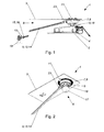
Fig. 1 eine erste bevorzugte Ausführungsform einer Sattelkupplung in Seitenansicht; -
Fig. 2 einen Teil der ersten bevorzugte Ausführungsform einer Sattelkupplung in axonometrischer Darstellung von schräg unten; -
Fig. 3 und 4 die erste bevorzugte Ausführungsform einer Sattelkupplung in axonometrischer Darstellung von schräg oben; -
Fig. 5 eine zweite bevorzugte Ausführungsform einer Sattelkupplung in Seitenansicht; -
Fig. 6 und7 die zweite bevorzugte Ausführungsform einer Sattelkupplung in axonometrischer Darstellung von schräg oben; -
Fig. 8 die zweite bevorzugte Ausführungsform einer Sattelkupplung als Teilschnitt in Seitenansicht; -
Fig. 9 die zweite bevorzugte Ausführungsform einer Sattelkupplung als Schnitt in Seitenansicht; -
Fig. 10 und 11 die zweite bevorzugte Ausführungsform einer Sattelkupplung als Teilschnitt in axonometrischer Darstellung von schräg oben;
-
Fig. 1 a first preferred embodiment of a fifth wheel in side view; -
Fig. 2 a part of the first preferred embodiment of a fifth wheel in axonometric view of obliquely from below; -
3 and 4 the first preferred embodiment of a fifth wheel in axonometric view obliquely from above; -
Fig. 5 a second preferred embodiment of a fifth wheel in side view; -
Fig. 6 and7 the second preferred embodiment of a fifth wheel in axonometric view obliquely from above; -
Fig. 8 the second preferred embodiment of a fifth wheel as a partial section in side view; -
Fig. 9 the second preferred embodiment of a fifth wheel as a section in side view; -
10 and 11 the second preferred embodiment of a fifth wheel as a partial section in axonometric view of obliquely from above;
Die
Die Sattelplatte 4 ist zur Montage an der Sattelzugmaschine 2 vorgesehen und kann dazu insbesondere an die Sattelzugmaschine 2 angeschraubt werden.The
Das Eingriffselement 5 ist zur Montage an den Sattelanhänger 3 montiert und kann dazu insbesondere an den Sattelanhänger 3 angeschraubt werden.The
Sattelplatte 4 und/oder Eingriffselement 5 können Stahl umfassen oder im Wesentlichen aus Stahl ausgebildet sein.
In den
Vorgesehen ist, dass eine Winkelmessvorrichtung 6 umfassend einen Drehwinkelaufnehmer 7 zur Messung des Drehwinkels zwischen dem Eingriffselement 5 und der Sattelplatte 4 vorgesehen ist. Hierbei entspricht der Drehwinkel zwischen dem Eingriffselement 5 und der Sattelplatte 4 dem Winkel zwischen der Längsrichtung der Sattelzugmaschine 2 und der Längsrichtung des Sattelanhängers 3. Der Drehwinkel beträgt in der Geradeausfahrt des Sattelzuges 0° und weicht in der Kurvenfahrt von 0° ab. Durch die Messung des Drehwinkels können lenkbare Achsen des Sattelanhängers 3 zwangsgelenkt werden, wobei durch die Zwangslenkung die Kurvenfahrt erleichtert wird und die Abnützung der Reifen gering gehalten werden kann.It is provided that an
Insbesondere kann ein Sattelzug umfassend eine Sattelzugmaschine 2 und einen Sattelanhänger 3 vorgesehen sein, wobei die Sattelzugmaschine 2 und der Sattelanhänger 3 mittels der vorteilhaft ausgebildeten Sattelkupplung 1 miteinander gekuppelt sind. Der Sattelzug kann hierbei für die Verwendung im Fernlastverkehr vorgesehen sein. Weiters kann vorgesehen sein, dass der Sattelzug für den Offroad-Bereich vorgesehen ist, beispielsweise für die Landwirtschaft oder den Bergbau. Weiters kann insbesondere vorgesehen sein, dass der Sattelzug als Schwerlasttransporter ausgebildet ist. Derartige Schwerlasttransporter weisen eine hohe Anzahl an Achsen auf.In particular, a semitrailer comprising a
Besonders bevorzugt kann vorgesehen sein, dass der Sattelanhänger 3 eine Zwangslenkung aufweist, und dass der Lenkwinkel der Zwangslenkung durch die Winkelmessvorrichtung 6 vorgegeben ist. Hierbei weist der Sattelanhänger 3 mindestens eine lenkbare Achse auf, welche mittels der Zwangslenkung gelenkt ist. Die Winkelmessvorrichtung 6 kann insbesondere ein Teil der Zwangslenkung sein.Particularly preferably it can be provided that the
Weiters kann ein Verfahren zur Zwangslenkung eines Sattelzuges vorgesehen sein, wobei ein Drehwinkel zwischen der Sattelzugmaschine 2 und dem Sattelanhänger 3 durch die Winkelmessvorrichtung 6 bestimmt wird, und anhand des gemessenen Drehwinkels mindestens eine zwangsgelenkte Achse des Sattelanhängers 3 gelenkt wird.Furthermore, a method for forced steering of a semitrailer may be provided, wherein a rotation angle between the
Besonders bevorzugt kann vorgesehen sein, dass das Eingriffselement 5 eine Kupplungskugel 17 aufweist. Hierbei kann die Sattelplatte 4 insbesondere eine Kugelpfanne 20 zur Aufnahme der Kupplungskugel 17 aufweisen. Die Kugelpfanne 20 kann dabei im Wesentlichen in deren Formgebung gegengleich zur Kupplungskugel 17 ausgebildet sein, womit die Kupplungskugel 17 zuverlässig von der Kugelpfanne 20 aufgenommen werden kann und die Kupplungskugel 17 zuverlässig in der Kugelpfanne 20 in sämtliche Richtungen verdreht werden kann, womit das in die Kugelpfanne 20 eingreifende Eingriffselement 5 rotiert und verkippt werden kann. Vorteilhaft dabei ist, dass die Drehung der Kupplungskugel 17 um einen definierten Punkt erfolgt, nämlich den Mittelpunkt der Kupplungskugel 17, wodurch eine definierte Kinematik gegeben ist. Vorteilhaft dabei ist, dass selbst bei großen Wank- oder Kippwinkeln zuverlässig Kräfte von der Sattelzugmaschine 2 zum Sattelanhänger 3 - und umgekehrt - übertragen werden können.Particularly preferably, it can be provided that the
In vorteilhafter Weiterbildung kann vorgesehen sein, dass angrenzend an die Kugelpfanne 20 eine Gleitführung 21 zur Führung der Kupplungskugel 17 zu der Kugelpfanne 20 angeordnet ist. Derart kann das Hinzuführen der Kupplungskugel 17 in die Kugelpfanne 20 vereinfacht werden. Zum Kuppeln kann die Sattelzugmaschine 2 rückwärts in Richtung des dabei stehenden Sattelanhängers 3 geschoben werden. Dabei kann die Kupplungskugel 17 einfach in die randseitig breite und schmäler zulaufende Gleitführung 21 eingeführt werden. Mittels der Gleitführung 21 kann - beim weiteren Rückwärtsschieben der Sattelzugmaschine 2 - die Kupplungskugel 17 weiter - im Wesentlichen selbsttätig - in Richtung der Kugelpfanne 20 geschoben werden.In an advantageous development it can be provided that adjacent to the
Weiters kann vorgesehen sein, dass die Kugelpfanne 20 einen Niederhalter 22 aufweist, wobei der Niederhalter 22 die Kupplungskugel 17 in der Kugelpfanne 20 hält.Furthermore, it can be provided that the
In
Insbesondere kann vorgesehen sein, dass an der Kupplungskugel 17 ein Hals 18 angeformt ist, und dass eine Verbindungslinie zwischen einem Mittelpunkt der Kupplungskugel 17 und dem Hals 18 einen Winkel zwischen 3° und 10° zu einer Horizontalen einschließt. Durch diese geknickte Verbindungslinie kann eine besonders gute Kräfteübertragung erreicht werden. Weiters kann dadurch ein großer Kippwinkel erreicht werden.In particular, it may be provided that on the
Alternativ kann vorgesehen sein, dass das Eingriffselement 5 einen Königszapfen aufweist.Alternatively it can be provided that the
Besonders bevorzugt kann vorgesehen sein, dass die Winkelmessvorrichtung 6 ein Ringelement 8 umfasst, dass das Ringelement 8 das Eingriffselement 5 zumindest teilweise, insbesondere vollständig, umschließt und bezüglich des Drehwinkels gegenüber dem Eingriffselement 5 verdrehbar gelagert ist, und dass das Ringelement 8 bezüglich des Drehwinkels lagefest zu der Sattelplatte 4 gehalten ist. Das Ringelement 8 kann insbesondere der äußere Ring eines Gleitlagers oder eines Kugellagers sein, wodurch sich das Ringelement 8 besonders leicht drehen lässt. Da das Ringelement 8 bezüglich des Drehwinkels lagefest zu der Sattelplatte 4 kann durch den Relativwinkel zwischen dem Ringelement 8 und dem Eingriffselement 5 der Drehwinkel einfach festgestellt werden. Hierbei kann die Messung des Drehwinkels rein mechanisch erfolgen. Durch das Ringelement 8 kann die Sattelkupplung 1 um 360° verdreht werden, wodurch der Drehwinkelaufnehmer 7 die Bewegungsfreiheit der Sattelkupplung 1 nicht einschränkt.Particularly preferably, it can be provided that the
Hierbei kann insbesondere vorgesehen sein, dass das Ringelement 8 einen Hals 18 des Eingriffselementes 5 umschließt, wobei eine Mittellinie des Halses im Wesentlichen durch den Mittelpunkt des Ringelementes 8 führt. Hierdurch kann eine besonders einfache und wenig verzerrte Kinematik zur Bestimmung des Drehwinkels erreich werden, da der Relativwinkel zwischen dem Ringelement 8 und dem Eingriffselement 5 im Wesentlichen dem Drehwinkel zwischen der Sattelzugmaschine 2 und dem Sattelanhänger 3 entspricht.In this case, provision may in particular be made for the ring element 8 to surround a
Hierbei kann vorgesehen sein, dass bei dem Verfahren zur Zwangslenkung eines Sattelzuges ein am Eingriffselement 5 drehbar gelagertes Ringelement 8 bezüglich des Drehwinkels lagefest zu der Sattelplatte 4 gehalten wird, und anhand des Relativwinkels zwischen dem Ringelement 8 und dem Eingriffselement 5 der Drehwinkel bestimmt wird.It can be provided that in the method for forced steering of a semitrailer on an engaging
Alternativ kann vorgesehen sein, dass der Drehwinkelaufnehmer 7 optoelektronisch ausgebildet ist. Hierbei kann auf der Sattelplatte 4 oder dem Eingriffselement 5 eine Kamera angeordnet sein, welche das gegenüberliegende Teil optisch erfasst und derart den Drehwinkel bestimmt.Alternatively it can be provided that the
Als weitere, nicht dargestellte, Alternative kann vorgesehen sein, dass der Drehwinkelaufnehmer 7 wenigstens einen die Sattelplatte 4 und dass Eingriffselement 5 verbindenden Hubkolben aufweist, wobei durch die Auslenkung des Hubkolbens auf den Drehwinkel rückgeschlossen werden kann.As another, not shown, alternative may be provided that the
Besonders bevorzugt kann vorgesehen sein, dass eine Haltestange 9 an einem ersten Ende an dem Ringelement 8 vertikal verschwenkbar gelagert ist und an einem zweiten Ende eine Nebenkuppelvorrichtung 10 zum schwenkbaren Kuppeln der Haltestange 9 an die Sattelzugmaschine 2 aufweist. Hierbei bildet die Haltestange 9 eine zumindest mittelbare Verbindung zwischen dem Ringelement 8 und der Sattelplatte 4, wobei durch die lediglich vertikale Verschwenkbarkeit der Haltestange 9 das Ringelement 8 gegenüber der Sattelplatte 4 bezüglich des Drehwinkels festgehalten wird, wobei das Ringelement 8 weiterhin einer Kipp- oder Wankbewegung folgen kann.Particularly preferably, it can be provided that a support rod 9 is mounted vertically pivotable at a first end to the ring member 8 and at a second end a Nebenkuppelvorrichtung 10 for pivotally coupling the support rod 9 to the
Die Haltestange 9 kann insbesondere in der Vertikalebene der Längsrichtung der Sattelzugmaschine 2 angeordnet sein. Weiters kann die Haltestange 9 einen Winkel zwischen 5° und 15° zu der Längsrichtung der Sattelzugmaschine 2 aufweisen.The support rod 9 may be arranged in particular in the vertical plane of the longitudinal direction of the
Durch die Haltestange 9 kann das Ringelement 8 bezüglich des Drehwinkels besonders robust und zuverlässig festgehalten werden.By the support rod 9, the ring member 8 are held particularly robust and reliable with respect to the rotation angle.
Alternativ kann vorgesehen sein, dass an der Sattelplatte 4 eine Führung in Richtung Ringelement 8 ragt, in welche ein Fortsatz des Ringelementes 8 eingreift.Alternatively, it can be provided that on the fifth wheel plate 4 a guide protrudes in the direction of ring element 8, in which an extension of the ring element 8 engages.
Als weitere Alternative zu der Haltestange 9 kann vorgesehen sein, dass in dem Ringelement 8 und der Sattelplatte 4 miteinander wechselwirkende Magnetanordnungen angeordnet sind, welche das Ringelement 8 bezüglich des Drehwinkels festhalten.As a further alternative to the support rod 9 can be provided that in the ring member 8 and the
Die Haltestange 9 kann hierbei insbesondere mittels eines Gabelgelenks 23 mit dem Ringelement 8 verbunden sein, wobei eine Drehachse des Gabelgelenkes 23 orthogonal zu einer Drehachse des Ringelementes 8 angeordnet ist. Das Gabelgelenk 23 gestattet hierbei dem Ringelement 8 eine hohe Bewegungsfreiheit bezüglich einer Wank- oder Kippbewegung, wobei eine Drehbewegung des Ringelementes 8 bezüglich der Sattelplatte 4 unterbunden wird.The support rod 9 can in this case be connected in particular by means of a fork joint 23 with the ring element 8, wherein a rotation axis of the fork joint 23 is arranged orthogonal to a rotation axis of the ring element 8. The fork joint 23 allows the ring member 8 a high freedom of movement with respect to a rolling or tilting movement, wherein a rotational movement of the ring member 8 is prevented with respect to the
Mittels der Nebenkuppelvorrichtung 10 kann die Haltestange 9 besonders einfach lösbar mit der Sattelzugmaschine 2 verbunden werden. Hierbei kann insbesondere vorgesehen sein, dass die Sattelzugmaschine 2 eine Nebenkupplungsaufnahme 19 zum Kuppeln mit der Nebenkuppelvorrichtung 10 aufweist. Hierbei kann ein Großteil der Winkelmessvorrichtung 6 an dem Sattelanhänger 3 angeordnet sein, wobei eine bestehende herkömmliche Sattelzugmaschine 2 einfach nachgerüstet werden kann.By means of the
Beim Kuppeln des Sattelzuges kann hierbei in einem ersten Schritt Sattelplatte 4 und Eingriffselement 5 miteinander gekuppelt werden und in einem zweiten Schritt die Nebenkuppelvorrichtung 10 mit der Nebenkupplungsaufnahme 19 gekuppelt werden.When coupling the semitrailer can here in a first step fifth wheel plate. 4 and
Alternativ kann vorgesehen sein, dass die Haltestange 9 an dem zweiten Ende schwenkbar mit der Sattelzugmaschine 2 verbindbar ist. Hierbei kann beispielsweise eine Trennung der Sattelkupplung an dem Gabelgelenk 23 erfolgen.Alternatively it can be provided that the holding rod 9 is pivotally connected to the
Besonders bevorzugt kann vorgesehen sein, dass die Haltestange 9 eine variierbare Länge aufweist. Hierbei kann die Haltestange 9 insbesondere als Hubkolben oder als Teleskopstange ausgebildet sein. Dadurch kann bei einer Kippbewegung der Abstand zwischen dem Gabelgelenk 23 und der Nebenkuppelvorrichtung 10 leicht variiert werden, wobei die Längenänderung gut messbar ist.Particularly preferably, it can be provided that the holding rod 9 has a variable length. Here, the support rod 9 may be formed in particular as a reciprocating piston or as a telescopic rod. As a result, in the case of a tilting movement, the distance between the fork joint 23 and the
Alternativ kann vorgesehen sein, dass an der Nebenkuppelvorrichtung 10 eine Öse angeordnet ist, wobei die Haltestange 9 beweglich bezüglich der Öse ist.Alternatively it can be provided that on the Nebenkuppelvorrichtung 10 an eyelet is arranged, wherein the support rod 9 is movable with respect to the eyelet.
Besonders bevorzugt kann vorgesehen sein, dass der Drehwinkelaufnehmer 7 einen elektronischen Winkelsensor 11 aufweist, und dass der Winkelsensor 11 den Drehwinkel zwischen dem Ringelement 8 und dem Eingriffselement 5 zumindest mittelbar misst. Durch den elektronischen Winkelsensor 11 kann der Drehwinkel leicht weiterverarbeitbar erfasst werden. Der Winkelsensor 11 kann hierbei unmittelbar benachbart zu dem Ringelement 8 angeordnet sein.Particularly preferably, it can be provided that the
Besonders bevorzugt kann vorgesehen sein, dass der Winkelsensor 11 optoelektronisch ausgebildet ist. Insbesondere kann der Winkelsensor 11 einen zum Eingriffselement 5 lagefesten Lichtsensor und eine am Ringelement 8 angeordnete Code-Scheibe umfassen. Hierbei kann der Drehwinkel auf einfache und zuverlässige Weise bestimmt werden. Ein derart ausgebildeter Winkelsensor 11 ist in den
Weiters kann vorgesehen sein, dass der Winkelsensor 11 als Drehpotenziometer ausgebildet ist.Furthermore, it can be provided that the
Alternativ kann vorgesehen sein, dass eine Magnetfeldanordnung in dem Ringelement 8 oder dem Eingriffselement 5 angeordnet ist, und der Winkelsensor 11 die Veränderung des Magnetfeldes misst.Alternatively it can be provided that a magnetic field arrangement is arranged in the ring element 8 or the
Besonders bevorzugt kann vorgesehen sein, dass das Ringelement 8 mit einem Getriebe 12 wirkverbunden ist, und dass das Getriebe 12 den Drehwinkel zwischen dem Ringelement 8 und dem Eingriffselement 5 mechanisch weiterleitet. Als Getriebe 12 wird hierbei eine Vorrichtung zum Übertragen der Drehbewegung verstanden. Das Getriebe 12 kann hierbei beispielsweise Zahnräder, Ketten, Zahnriemen, Keilriemen und dergleichen umfassen. Hierbei kann vorgesehen sein, dass das Getriebe 12 eine Umwandlung der Drehbewegung, also eine Übersetzung oder Untersetzung der Drehbewegung, bewerkstelligt. Durch das Getriebe 2 kann die Drehbewegung zunächst mechanisch von dem Eingriffselement 5 weggeführt werden, wobei die Drehbewegung anschließend mittels des Winkelsensors 11 in ein elektrisches Signal umgewandelt werden kann, oder direkt mechanisch zu der Zwangslenkung weitergeleitet werden kann.Particularly preferably, it may be provided that the ring element 8 is operatively connected to a
Es kann weiters vorgesehen sein, dass an dem Ringelement 8 ein Zahnradelement 24 befestigt, insbesondere angeformt, ist. Durch das Zahnradelement 24 kann die Drehbewegung des Ringelementes 8 präzise an das Getriebe 12 weitergegeben werden.It may further be provided that attached to the ring member 8, a
Weiters kann vorgesehen sein, dass zwischen an dem Übergang zwischen dem Ringelement 8 und dem Zahnradelement 24 eine Abdeckplatte 25 angeordnet ist, welche das Getriebe 12 von der Umwelt abschirmt.Furthermore, it can be provided that between the ring member 8 and the
Besonders bevorzugt kann vorgesehen sein, dass das Getriebe 2 mit der Zwangslenkung mechanisch wirkverbunden ist, wobei eine Drehbewegung des Ringelementes 2 lediglich mechanisch an die Zwangslenkung weitergeleitet wird. Dadurch entfällt eine Umwandlung in elektronische Signale.Particularly preferably it can be provided that the
Insbesondere kann vorgesehen sein, dass das Getriebe 12 das Ringelement 8 mit einem Messrad 26 verbindet. Das Messrad 26 kann vorgesehen sein zur drehbar gelagerten Montage an dem Sattelanhänger 3. Das Messrad 26 kann hierbei die Drehbewegung des Ringelementes 8 in eine elektronisch weiterverarbeitbares elektrisches Signal umwandeln, wobei das Messrad 26 einen elektronischen Winkelsensor 11 darstellt. Hierbei kann vorgesehen sein, dass das Zahnradelement 24 und das Messrad 26 mittels eines als Zahnriemen ausgebildeten Getriebes 12 miteinander wirkverbunden sind. Eine derartige bevorzugte Ausführungsform ist in den
Besonders bevorzugt kann vorgesehen sein, dass die Winkelmessvorrichtung 6 einen Kippwinkelaufnehmer 13 zum Messen des Kippwinkels zwischen dem Eingriffselement 5 und der Sattelplatte 4 aufweist. Hierbei kann vorgesehen sein, dass der Kippwinkel zwischen dem Eingriffselement 5 und der Sattelplatte 4 mittels eines Kippwinkelaufnehmers 13 der Winkelmessvorrichtung 6 gemessen wird. Der Kippwinkel ist - in Geradeausfahrt des Sattelzuges - der Winkel um eine Drehachse, welche horizontal und orthogonal zu der Längsrichtung des Sattelzuges verläuft. Durch die Messung des Kippwinkels kann dem Fahrer des Sattelzuges angezeigt werden, ob eine Abkuppeln gefahrlos möglich ist. Weiters kann der Kippwinkel verwendet werden, um Nichtlinearitäten bei der Ermittlung des Drehwinkels aus dem Relativwinkel zwischen Ringelement 8 und Eingriffselement 5 zu bestimmen. Derartige Nichtlinearitäten können insbesondere bei hohen Kippwinkeln auftreten.Particularly preferably, it can be provided that the
Besonders bevorzugt kann vorgesehen sein, dass der maximale Kippwinkel der Sattelkupplung mindestens 20° in beide Richtungen beträgt.Particularly preferably, it can be provided that the maximum tilt angle of the fifth wheel is at least 20 ° in both directions.
Insbesondere kann vorgesehen sein, dass der Kippwinkelaufnehmer 13 einen Abstandsensor 14 zur Aufnahme des Abstandes zwischen dem ersten Ende der Haltestange 9 und der Nebenkuppelvorrichtung 10 aufweist. Der Abstandsensor 14 kann insbesondere als ein in der Haltestange 9 integrierter Hubkolben ausgebildet sein. Dadurch kann der Abstandsensor 14 besonders einfach ausgebildet sein. In einer Geradeausfahrt des Sattelzuges kann der Kippwinkel direkt durch diesen Abstand bestimmt werden.In particular, it can be provided that the Kippwinkelaufnehmer 13 has a distance sensor 14 for receiving the distance between the first end of the support rod 9 and the
Alternativ kann vorgesehen sein, dass Abstandsensor 14 optoelektronisch ausgebildet ist, wobei der gemessene Lichtstrahl im Wesentlichen parallel zu der Haltestange 9 verläuft.Alternatively it can be provided that the distance sensor 14 is formed opto-electronically, wherein the measured light beam is substantially parallel to the support rod 9.
Gemäß einer nicht dargestellten Ausführungsform kann vorgesehen sein, dass der Kippwinkelaufnehmer 13 einen zur Sattelplatte 4 lagefesten ersten Neigungssensor aufweist und einen zum Eingriffselement 5 lagefesten zweiten Neigungssensor aufweist, wobei der Kippwinkel durch den Vergleich der beiden Neigungssensoren bestimmt wird.According to an embodiment, not shown, it can be provided that the Kippwinkelaufnehmer 13 has a position fixed to the
Besonders bevorzugt kann vorgesehen sein, dass die Winkelmessvorrichtung 6 einen Wankwinkelaufnehmer 15 zum Messen des Wankwinkels zwischen dem Eingriffselement 5 und der Sattelplatte 4 aufweist. Hierbei kann vorgesehen sein, dass der Wankwinkel zwischen dem Eingriffselement 5 und der Sattelplatte 4 mittels des Wankwinkelaufnehmers 15 der Winkelmessvorrichtung 6 gemessen wird. Der Wankwinkel ist - in Geradeausfahrt des Sattelzuges - der Winkel um eine Drehachse, welche parallel zu der Längsrichtung des Sattelzuges verläuft. Durch die Messung des Wankwinkels kann eine Warnung an den Fahrer ausgegeben werden, wenn der Sattelanhänger 3 stark ins Wanken gerät. Weiters kann vorgesehen sein, dass der Sattelanhänger 3 eine Stabilisierungsvorrichtung aufweist, welche starke Wankbewegungen des Sattelanhängers 3, beispielsweise durch die Veränderung der Federung der Radaufhängung, automatisch unterbinden kann. Weiters kann der Wankwinkel verwendet werden, um Nichtlinearitäten bei der Ermittlung des Drehwinkels aus dem Relativwinkel zwischen Ringelement 8 und Eingriffselement 5 zu bestimmen. Derartige Nichtlinearitäten können insbesondere bei hohen Wankwinkeln auftreten.Particularly preferably, it can be provided that the
Besonders bevorzugt kann vorgesehen sein, dass der maximale Wankwinkel der Sattelkupplung mindestens 20° in beide Richtungen beträgt.Particularly preferably, it can be provided that the maximum roll angle of the fifth wheel is at least 20 ° in both directions.
Insbesondere kann vorgesehen sein, dass der Wankwinkelaufnehmer 15 einen Verdrehungssensor 16 zur Aufnahme einer Verdrehung der Haltestange 9 um deren Längsachse aufweist. Dadurch kann der Wankwinkelaufnehmer 15 besonders einfach ausgebildet sein. Sofern die Haltestange 9 im Wesentlichen parallel zu der Längsachse der Sattelzugmaschine 2 verläuft, entspricht die Verdrehung der Haltestange 9 bei einer Geradeausfahrt im Wesentlichen dem Wankwinkel.In particular, it can be provided that the roll angle sensor 15 has a rotation sensor 16 for receiving a rotation of the support rod 9 about its longitudinal axis. As a result, the roll angle sensor 15 can be designed to be particularly simple. If the support rod 9 extends substantially parallel to the longitudinal axis of the
Gemäß einer nicht dargestellten Ausführungsform kann vorgesehen sein, dass der Wankwinkelaufnehmer 15 einen zur Sattelplatte 4 lagefesten ersten Neigungssensor aufweist und einen zum Eingriffselement 5 lagefesten zweiten Neigungssensor aufweist, wobei der Wankwinkel durch den Vergleich der beiden Neigungssensoren bestimmt wird.According to an embodiment, not shown, it may be provided that the roll angle sensor 15 has a first inclination sensor fixed to the
Besonders bevorzugt kann vorgesehen sein, dass die Winkelmessvorrichtung 6 eine Steuereinheit umfasst, und dass die Steuereinheit am Eingang wenigstens mit dem Drehwinkelaufnehmer 7 wirkverbunden ist. Die Steuereinheit kann ausgangsseitig mit der Zwangslenkung des Sattelanhängers 3 wirkverbunden sein.Particularly preferably, it can be provided that the
Besonders bevorzugt kann vorgesehen sein, dass die Steuereinheit am Eingang mit dem Kippwinkelaufnehmer 13 und dem Wankwinkelaufnehmer 15 verbunden ist. Hierbei hat die Steuereinheit als Eingangsgrößen die Messwerte des Drehwinkelaufnehmers 7, des Kippwinkelaufnehmers 13 und des Wankwinkelaufnehmers 15. Hierbei können der Drehwinkelaufnehmer 7, der Kippwinkelaufnehmer 13 und der Wankwinkelaufnehmer 15 Messgrößen ausgeben, welche zur Ermittlung des tatsächlichen Drehwinkels, Kippwinkels oder Wankwinkels in der Steuereinheit miteinander kombiniert werden können. Bei einem großen Drehwinkel hängt der Kippwinkel beispielsweise stark von der ausgegebenen Messgröße des Wankwinkelaufnehmers 15 ab. Die Steuereinheit kann hierbei insbesondere Tabellen von den Messgrößen der Aufnehmer und den entsprechenden Winkeln aufweisen. Durch die Kombination von zwei, insbesondere aller drei, Messgrößen der drei Aufnehmer können die betreffenden Winkel auch bei großen Verwindungen der Sattelkupplung zuverlässig ermittelt werden.Particularly preferably, it can be provided that the control unit is connected at the input to the tilt angle sensor 13 and the roll angle sensor 15. In this case, the control unit has as inputs the measured values of the
Weiters kann vorgesehen sein, dass die Steuereinheit ausgangsseitig Stabilisierungsvorrichtung wirkverbunden ist.Furthermore, it can be provided that the control unit on the output side stabilizing device is operatively connected.
Claims (15)
Applications Claiming Priority (1)
| Application Number | Priority Date | Filing Date | Title |
|---|---|---|---|
| ATA491/2013A AT514448B1 (en) | 2013-06-18 | 2013-06-18 | fifth wheel |
Publications (2)
| Publication Number | Publication Date |
|---|---|
| EP2815950A1 true EP2815950A1 (en) | 2014-12-24 |
| EP2815950B1 EP2815950B1 (en) | 2016-08-17 |
Family
ID=51133980
Family Applications (1)
| Application Number | Title | Priority Date | Filing Date |
|---|---|---|---|
| EP14450029.5A Not-in-force EP2815950B1 (en) | 2013-06-18 | 2014-06-04 | Fifth wheel |
Country Status (2)
| Country | Link |
|---|---|
| EP (1) | EP2815950B1 (en) |
| AT (1) | AT514448B1 (en) |
Cited By (3)
| Publication number | Priority date | Publication date | Assignee | Title |
|---|---|---|---|---|
| DE102017126503A1 (en) | 2017-11-10 | 2019-05-16 | Syn Trac Gmbh | Ball head device with rotation angle sensor device |
| WO2021115768A1 (en) * | 2019-12-11 | 2021-06-17 | Saf-Holland Gmbh | Kingpin assembly and bend angle measurement system |
| EP3954554A1 (en) * | 2020-08-13 | 2022-02-16 | SAF-HOLLAND GmbH | Clutch system with bend angle measurement |
Families Citing this family (5)
| Publication number | Priority date | Publication date | Assignee | Title |
|---|---|---|---|---|
| EP3379222B1 (en) | 2017-03-22 | 2020-12-30 | Methode Electronics Malta Ltd. | Magnetoelastic based sensor assembly |
| US11084342B2 (en) | 2018-02-27 | 2021-08-10 | Methode Electronics, Inc. | Towing systems and methods using magnetic field sensing |
| US11135882B2 (en) | 2018-02-27 | 2021-10-05 | Methode Electronics, Inc. | Towing systems and methods using magnetic field sensing |
| US11491832B2 (en) | 2018-02-27 | 2022-11-08 | Methode Electronics, Inc. | Towing systems and methods using magnetic field sensing |
| US11221262B2 (en) | 2018-02-27 | 2022-01-11 | Methode Electronics, Inc. | Towing systems and methods using magnetic field sensing |
Citations (4)
| Publication number | Priority date | Publication date | Assignee | Title |
|---|---|---|---|---|
| US20060145450A1 (en) * | 2003-05-02 | 2006-07-06 | Heinz-Rudiger Metternich | Control device for a tractor provided with a system for detecting pivoting and articulation angles between said tractor and a trailer |
| US20070216134A1 (en) * | 2006-02-10 | 2007-09-20 | Padula Santo A | Trailer steering system for a tractor/trailer combination |
| WO2009019444A1 (en) * | 2007-08-03 | 2009-02-12 | Cambridge Enterprise Limited | Active steering controller |
| US20130082453A1 (en) * | 2011-10-04 | 2013-04-04 | Santo A. Padula | Apparatus for measuring articulation angle between a tractor and trailer in an articulated vehicle |
Family Cites Families (4)
| Publication number | Priority date | Publication date | Assignee | Title |
|---|---|---|---|---|
| DE4021717A1 (en) * | 1990-07-07 | 1992-01-09 | Jost Werke Gmbh | Measuring pivot angle between tractor and trailer of articulated lorry - using measurement wheel and angle transducer on coupling plate |
| DE102007020770A1 (en) * | 2007-05-03 | 2008-11-13 | Bubenzer Bremsen Gerhard Bubenzer Ing. Gmbh | coupling device |
| AT507606B1 (en) * | 2008-11-28 | 2010-11-15 | Josef Ing Scharmueller | FIFTH WHEEL |
| DE102009002334B4 (en) * | 2009-04-09 | 2012-09-27 | Jost-Werke Gmbh | Control system with a displacement device for a fifth wheel arranged on a towing vehicle |
-
2013
- 2013-06-18 AT ATA491/2013A patent/AT514448B1/en not_active IP Right Cessation
-
2014
- 2014-06-04 EP EP14450029.5A patent/EP2815950B1/en not_active Not-in-force
Patent Citations (4)
| Publication number | Priority date | Publication date | Assignee | Title |
|---|---|---|---|---|
| US20060145450A1 (en) * | 2003-05-02 | 2006-07-06 | Heinz-Rudiger Metternich | Control device for a tractor provided with a system for detecting pivoting and articulation angles between said tractor and a trailer |
| US20070216134A1 (en) * | 2006-02-10 | 2007-09-20 | Padula Santo A | Trailer steering system for a tractor/trailer combination |
| WO2009019444A1 (en) * | 2007-08-03 | 2009-02-12 | Cambridge Enterprise Limited | Active steering controller |
| US20130082453A1 (en) * | 2011-10-04 | 2013-04-04 | Santo A. Padula | Apparatus for measuring articulation angle between a tractor and trailer in an articulated vehicle |
Cited By (4)
| Publication number | Priority date | Publication date | Assignee | Title |
|---|---|---|---|---|
| DE102017126503A1 (en) | 2017-11-10 | 2019-05-16 | Syn Trac Gmbh | Ball head device with rotation angle sensor device |
| DE102017126503A8 (en) * | 2017-11-10 | 2019-08-01 | Syn Trac Gmbh | Ball head device with rotation angle sensor device |
| WO2021115768A1 (en) * | 2019-12-11 | 2021-06-17 | Saf-Holland Gmbh | Kingpin assembly and bend angle measurement system |
| EP3954554A1 (en) * | 2020-08-13 | 2022-02-16 | SAF-HOLLAND GmbH | Clutch system with bend angle measurement |
Also Published As
| Publication number | Publication date |
|---|---|
| EP2815950B1 (en) | 2016-08-17 |
| AT514448B1 (en) | 2015-03-15 |
| AT514448A1 (en) | 2015-01-15 |
Similar Documents
| Publication | Publication Date | Title |
|---|---|---|
| EP2815950B1 (en) | Fifth wheel | |
| EP2110271B1 (en) | Trailer tow-bar | |
| DE102009028000A1 (en) | Steering device for a trailer vehicle | |
| EP2634018B1 (en) | Dolly axle | |
| DE102010021052A1 (en) | Reversing aid device for controlling a reverse drive of a vehicle combination | |
| DE102008004159A1 (en) | Driver aiding method for use during maneuvering towing vehicle of e.g. trailer, involves adjusting supporting steering angle at rear axle of towing vehicle depending on predetermined steering angle of steerable wheel of towing vehicle | |
| DE102008004158A1 (en) | Stabilization device for stabilizing reverse movement of towing vehicle of e.g. trailer, has controlling unit for adjusting stabilization steering angle at rear axis of towing vehicle depending on predetermined steering angle | |
| DE102015103972A1 (en) | Joint angle sensor arrangement | |
| EP2243688B1 (en) | Corrected forced steering for steered trailers or semi-trailers on multiple axle steering agricultural or forestry traction vehicles | |
| DE602005000712T2 (en) | Semitrailer or trailer with improved steering control | |
| DE4127750C1 (en) | Automotive equipment improving stability of car and trailer linkage - uses sensors or measurement value pick=ups to register undesired swing of trailer and automatic auxiliary linkage to counteract it | |
| EP2883435B1 (en) | Agricultural vehicle combination | |
| EP2353970B1 (en) | Forced steering | |
| EP3427560B1 (en) | Towing device | |
| AT518246B1 (en) | METHOD FOR OPERATING A FORCED STEERING DEVICE | |
| DE174865C (en) | ||
| EP3707058B1 (en) | Method for steering a vehicle | |
| DE1932815B2 (en) | All-terrain two-axle vehicle with two- or four-wheel drive | |
| EP2910099B1 (en) | Method for calibrating a drawn or self-propelled utility vehicle provided with at least one steerable axle | |
| EP0033873A1 (en) | Trailer train with reduced distance between traction vehicle and trailer | |
| DE102018117353A1 (en) | Method for determining the articulation angle in a vehicle combination | |
| WO2018095899A1 (en) | Measuring device for measuring an articulation angle and vehicle combination | |
| DE3139349A1 (en) | Control for a trailing steering axle in single-element or multi-element vehicles | |
| DE202020107400U1 (en) | Steering pivot and steering knuckle arrangement | |
| DE102019105239A1 (en) | Coupling device of a tugger train |
Legal Events
| Date | Code | Title | Description |
|---|---|---|---|
| PUAI | Public reference made under article 153(3) epc to a published international application that has entered the european phase |
Free format text: ORIGINAL CODE: 0009012 |
|
| 17P | Request for examination filed |
Effective date: 20140604 |
|
| AK | Designated contracting states |
Kind code of ref document: A1 Designated state(s): AL AT BE BG CH CY CZ DE DK EE ES FI FR GB GR HR HU IE IS IT LI LT LU LV MC MK MT NL NO PL PT RO RS SE SI SK SM TR |
|
| AX | Request for extension of the european patent |
Extension state: BA ME |
|
| RAP1 | Party data changed (applicant data changed or rights of an application transferred) |
Owner name: SCHARMUELLER, JOSEF, JUN. Owner name: SCHARMUELLER, JOSEF |
|
| R17P | Request for examination filed (corrected) |
Effective date: 20150624 |
|
| RBV | Designated contracting states (corrected) |
Designated state(s): AL AT BE BG CH CY CZ DE DK EE ES FI FR GB GR HR HU IE IS IT LI LT LU LV MC MK MT NL NO PL PT RO RS SE SI SK SM TR |
|
| GRAP | Despatch of communication of intention to grant a patent |
Free format text: ORIGINAL CODE: EPIDOSNIGR1 |
|
| INTG | Intention to grant announced |
Effective date: 20160421 |
|
| GRAS | Grant fee paid |
Free format text: ORIGINAL CODE: EPIDOSNIGR3 |
|
| GRAA | (expected) grant |
Free format text: ORIGINAL CODE: 0009210 |
|
| AK | Designated contracting states |
Kind code of ref document: B1 Designated state(s): AL AT BE BG CH CY CZ DE DK EE ES FI FR GB GR HR HU IE IS IT LI LT LU LV MC MK MT NL NO PL PT RO RS SE SI SK SM TR |
|
| REG | Reference to a national code |
Ref country code: GB Ref legal event code: FG4D Free format text: NOT ENGLISH |
|
| REG | Reference to a national code |
Ref country code: CH Ref legal event code: EP |
|
| REG | Reference to a national code |
Ref country code: IE Ref legal event code: FG4D Free format text: LANGUAGE OF EP DOCUMENT: GERMAN |
|
| REG | Reference to a national code |
Ref country code: AT Ref legal event code: REF Ref document number: 820749 Country of ref document: AT Kind code of ref document: T Effective date: 20160915 |
|
| REG | Reference to a national code |
Ref country code: DE Ref legal event code: R096 Ref document number: 502014001265 Country of ref document: DE |
|
| REG | Reference to a national code |
Ref country code: NL Ref legal event code: MP Effective date: 20160817 |
|
| REG | Reference to a national code |
Ref country code: LT Ref legal event code: MG4D |
|
| PG25 | Lapsed in a contracting state [announced via postgrant information from national office to epo] |
Ref country code: HR Free format text: LAPSE BECAUSE OF FAILURE TO SUBMIT A TRANSLATION OF THE DESCRIPTION OR TO PAY THE FEE WITHIN THE PRESCRIBED TIME-LIMIT Effective date: 20160817 Ref country code: NL Free format text: LAPSE BECAUSE OF FAILURE TO SUBMIT A TRANSLATION OF THE DESCRIPTION OR TO PAY THE FEE WITHIN THE PRESCRIBED TIME-LIMIT Effective date: 20160817 Ref country code: RS Free format text: LAPSE BECAUSE OF FAILURE TO SUBMIT A TRANSLATION OF THE DESCRIPTION OR TO PAY THE FEE WITHIN THE PRESCRIBED TIME-LIMIT Effective date: 20160817 Ref country code: FI Free format text: LAPSE BECAUSE OF FAILURE TO SUBMIT A TRANSLATION OF THE DESCRIPTION OR TO PAY THE FEE WITHIN THE PRESCRIBED TIME-LIMIT Effective date: 20160817 Ref country code: NO Free format text: LAPSE BECAUSE OF FAILURE TO SUBMIT A TRANSLATION OF THE DESCRIPTION OR TO PAY THE FEE WITHIN THE PRESCRIBED TIME-LIMIT Effective date: 20161117 Ref country code: LT Free format text: LAPSE BECAUSE OF FAILURE TO SUBMIT A TRANSLATION OF THE DESCRIPTION OR TO PAY THE FEE WITHIN THE PRESCRIBED TIME-LIMIT Effective date: 20160817 |
|
| PG25 | Lapsed in a contracting state [announced via postgrant information from national office to epo] |
Ref country code: PL Free format text: LAPSE BECAUSE OF FAILURE TO SUBMIT A TRANSLATION OF THE DESCRIPTION OR TO PAY THE FEE WITHIN THE PRESCRIBED TIME-LIMIT Effective date: 20160817 Ref country code: SE Free format text: LAPSE BECAUSE OF FAILURE TO SUBMIT A TRANSLATION OF THE DESCRIPTION OR TO PAY THE FEE WITHIN THE PRESCRIBED TIME-LIMIT Effective date: 20160817 Ref country code: LV Free format text: LAPSE BECAUSE OF FAILURE TO SUBMIT A TRANSLATION OF THE DESCRIPTION OR TO PAY THE FEE WITHIN THE PRESCRIBED TIME-LIMIT Effective date: 20160817 Ref country code: PT Free format text: LAPSE BECAUSE OF FAILURE TO SUBMIT A TRANSLATION OF THE DESCRIPTION OR TO PAY THE FEE WITHIN THE PRESCRIBED TIME-LIMIT Effective date: 20161219 Ref country code: ES Free format text: LAPSE BECAUSE OF FAILURE TO SUBMIT A TRANSLATION OF THE DESCRIPTION OR TO PAY THE FEE WITHIN THE PRESCRIBED TIME-LIMIT Effective date: 20160817 Ref country code: GR Free format text: LAPSE BECAUSE OF FAILURE TO SUBMIT A TRANSLATION OF THE DESCRIPTION OR TO PAY THE FEE WITHIN THE PRESCRIBED TIME-LIMIT Effective date: 20161118 |
|
| PG25 | Lapsed in a contracting state [announced via postgrant information from national office to epo] |
Ref country code: EE Free format text: LAPSE BECAUSE OF FAILURE TO SUBMIT A TRANSLATION OF THE DESCRIPTION OR TO PAY THE FEE WITHIN THE PRESCRIBED TIME-LIMIT Effective date: 20160817 Ref country code: RO Free format text: LAPSE BECAUSE OF FAILURE TO SUBMIT A TRANSLATION OF THE DESCRIPTION OR TO PAY THE FEE WITHIN THE PRESCRIBED TIME-LIMIT Effective date: 20160817 |
|
| REG | Reference to a national code |
Ref country code: DE Ref legal event code: R097 Ref document number: 502014001265 Country of ref document: DE |
|
| PG25 | Lapsed in a contracting state [announced via postgrant information from national office to epo] |
Ref country code: CZ Free format text: LAPSE BECAUSE OF FAILURE TO SUBMIT A TRANSLATION OF THE DESCRIPTION OR TO PAY THE FEE WITHIN THE PRESCRIBED TIME-LIMIT Effective date: 20160817 Ref country code: DK Free format text: LAPSE BECAUSE OF FAILURE TO SUBMIT A TRANSLATION OF THE DESCRIPTION OR TO PAY THE FEE WITHIN THE PRESCRIBED TIME-LIMIT Effective date: 20160817 Ref country code: SK Free format text: LAPSE BECAUSE OF FAILURE TO SUBMIT A TRANSLATION OF THE DESCRIPTION OR TO PAY THE FEE WITHIN THE PRESCRIBED TIME-LIMIT Effective date: 20160817 Ref country code: SM Free format text: LAPSE BECAUSE OF FAILURE TO SUBMIT A TRANSLATION OF THE DESCRIPTION OR TO PAY THE FEE WITHIN THE PRESCRIBED TIME-LIMIT Effective date: 20160817 Ref country code: BG Free format text: LAPSE BECAUSE OF FAILURE TO SUBMIT A TRANSLATION OF THE DESCRIPTION OR TO PAY THE FEE WITHIN THE PRESCRIBED TIME-LIMIT Effective date: 20161117 |
|
| REG | Reference to a national code |
Ref country code: FR Ref legal event code: PLFP Year of fee payment: 4 |
|
| PLBE | No opposition filed within time limit |
Free format text: ORIGINAL CODE: 0009261 |
|
| STAA | Information on the status of an ep patent application or granted ep patent |
Free format text: STATUS: NO OPPOSITION FILED WITHIN TIME LIMIT |
|
| 26N | No opposition filed |
Effective date: 20170518 |
|
| PG25 | Lapsed in a contracting state [announced via postgrant information from national office to epo] |
Ref country code: SI Free format text: LAPSE BECAUSE OF FAILURE TO SUBMIT A TRANSLATION OF THE DESCRIPTION OR TO PAY THE FEE WITHIN THE PRESCRIBED TIME-LIMIT Effective date: 20160817 |
|
| PG25 | Lapsed in a contracting state [announced via postgrant information from national office to epo] |
Ref country code: MC Free format text: LAPSE BECAUSE OF FAILURE TO SUBMIT A TRANSLATION OF THE DESCRIPTION OR TO PAY THE FEE WITHIN THE PRESCRIBED TIME-LIMIT Effective date: 20160817 |
|
| REG | Reference to a national code |
Ref country code: CH Ref legal event code: PL |
|
| REG | Reference to a national code |
Ref country code: IE Ref legal event code: MM4A |
|
| PG25 | Lapsed in a contracting state [announced via postgrant information from national office to epo] |
Ref country code: LU Free format text: LAPSE BECAUSE OF NON-PAYMENT OF DUE FEES Effective date: 20170604 Ref country code: CH Free format text: LAPSE BECAUSE OF NON-PAYMENT OF DUE FEES Effective date: 20170630 Ref country code: LI Free format text: LAPSE BECAUSE OF NON-PAYMENT OF DUE FEES Effective date: 20170630 Ref country code: IE Free format text: LAPSE BECAUSE OF NON-PAYMENT OF DUE FEES Effective date: 20170604 |
|
| REG | Reference to a national code |
Ref country code: BE Ref legal event code: MM Effective date: 20170630 |
|
| REG | Reference to a national code |
Ref country code: FR Ref legal event code: PLFP Year of fee payment: 5 |
|
| PG25 | Lapsed in a contracting state [announced via postgrant information from national office to epo] |
Ref country code: BE Free format text: LAPSE BECAUSE OF NON-PAYMENT OF DUE FEES Effective date: 20170630 |
|
| PG25 | Lapsed in a contracting state [announced via postgrant information from national office to epo] |
Ref country code: MT Free format text: LAPSE BECAUSE OF FAILURE TO SUBMIT A TRANSLATION OF THE DESCRIPTION OR TO PAY THE FEE WITHIN THE PRESCRIBED TIME-LIMIT Effective date: 20160817 |
|
| PG25 | Lapsed in a contracting state [announced via postgrant information from national office to epo] |
Ref country code: AL Free format text: LAPSE BECAUSE OF FAILURE TO SUBMIT A TRANSLATION OF THE DESCRIPTION OR TO PAY THE FEE WITHIN THE PRESCRIBED TIME-LIMIT Effective date: 20160817 |
|
| GBPC | Gb: european patent ceased through non-payment of renewal fee |
Effective date: 20180604 |
|
| PG25 | Lapsed in a contracting state [announced via postgrant information from national office to epo] |
Ref country code: GB Free format text: LAPSE BECAUSE OF NON-PAYMENT OF DUE FEES Effective date: 20180604 |
|
| PG25 | Lapsed in a contracting state [announced via postgrant information from national office to epo] |
Ref country code: HU Free format text: LAPSE BECAUSE OF FAILURE TO SUBMIT A TRANSLATION OF THE DESCRIPTION OR TO PAY THE FEE WITHIN THE PRESCRIBED TIME-LIMIT; INVALID AB INITIO Effective date: 20140604 |
|
| PG25 | Lapsed in a contracting state [announced via postgrant information from national office to epo] |
Ref country code: CY Free format text: LAPSE BECAUSE OF FAILURE TO SUBMIT A TRANSLATION OF THE DESCRIPTION OR TO PAY THE FEE WITHIN THE PRESCRIBED TIME-LIMIT Effective date: 20160817 |
|
| PG25 | Lapsed in a contracting state [announced via postgrant information from national office to epo] |
Ref country code: MK Free format text: LAPSE BECAUSE OF FAILURE TO SUBMIT A TRANSLATION OF THE DESCRIPTION OR TO PAY THE FEE WITHIN THE PRESCRIBED TIME-LIMIT Effective date: 20160817 |
|
| PG25 | Lapsed in a contracting state [announced via postgrant information from national office to epo] |
Ref country code: TR Free format text: LAPSE BECAUSE OF FAILURE TO SUBMIT A TRANSLATION OF THE DESCRIPTION OR TO PAY THE FEE WITHIN THE PRESCRIBED TIME-LIMIT Effective date: 20160817 |
|
| PG25 | Lapsed in a contracting state [announced via postgrant information from national office to epo] |
Ref country code: IS Free format text: LAPSE BECAUSE OF FAILURE TO SUBMIT A TRANSLATION OF THE DESCRIPTION OR TO PAY THE FEE WITHIN THE PRESCRIBED TIME-LIMIT Effective date: 20161217 |
|
| PGFP | Annual fee paid to national office [announced via postgrant information from national office to epo] |
Ref country code: DE Payment date: 20200623 Year of fee payment: 7 Ref country code: FR Payment date: 20200623 Year of fee payment: 7 |
|
| REG | Reference to a national code |
Ref country code: AT Ref legal event code: MM01 Ref document number: 820749 Country of ref document: AT Kind code of ref document: T Effective date: 20190604 |
|
| PG25 | Lapsed in a contracting state [announced via postgrant information from national office to epo] |
Ref country code: AT Free format text: LAPSE BECAUSE OF NON-PAYMENT OF DUE FEES Effective date: 20190604 |
|
| PGFP | Annual fee paid to national office [announced via postgrant information from national office to epo] |
Ref country code: IT Payment date: 20200630 Year of fee payment: 7 |
|
| REG | Reference to a national code |
Ref country code: DE Ref legal event code: R119 Ref document number: 502014001265 Country of ref document: DE |
|
| PG25 | Lapsed in a contracting state [announced via postgrant information from national office to epo] |
Ref country code: DE Free format text: LAPSE BECAUSE OF NON-PAYMENT OF DUE FEES Effective date: 20220101 |
|
| PG25 | Lapsed in a contracting state [announced via postgrant information from national office to epo] |
Ref country code: FR Free format text: LAPSE BECAUSE OF NON-PAYMENT OF DUE FEES Effective date: 20210630 |
|
| PG25 | Lapsed in a contracting state [announced via postgrant information from national office to epo] |
Ref country code: IT Free format text: LAPSE BECAUSE OF NON-PAYMENT OF DUE FEES Effective date: 20210604 |